EP2752976A2 - Enhanced cooling of enclosed air cooled high power motors - Google Patents
Enhanced cooling of enclosed air cooled high power motors Download PDFInfo
- Publication number
- EP2752976A2 EP2752976A2 EP14150303.7A EP14150303A EP2752976A2 EP 2752976 A2 EP2752976 A2 EP 2752976A2 EP 14150303 A EP14150303 A EP 14150303A EP 2752976 A2 EP2752976 A2 EP 2752976A2
- Authority
- EP
- European Patent Office
- Prior art keywords
- rotor
- shaft
- fan
- motor assembly
- stator
- Prior art date
- Legal status (The legal status is an assumption and is not a legal conclusion. Google has not performed a legal analysis and makes no representation as to the accuracy of the status listed.)
- Withdrawn
Links
Images



Classifications
-
- H—ELECTRICITY
- H02—GENERATION; CONVERSION OR DISTRIBUTION OF ELECTRIC POWER
- H02K—DYNAMO-ELECTRIC MACHINES
- H02K9/00—Arrangements for cooling or ventilating
- H02K9/08—Arrangements for cooling or ventilating by gaseous cooling medium circulating wholly within the machine casing
-
- H—ELECTRICITY
- H02—GENERATION; CONVERSION OR DISTRIBUTION OF ELECTRIC POWER
- H02K—DYNAMO-ELECTRIC MACHINES
- H02K9/00—Arrangements for cooling or ventilating
- H02K9/14—Arrangements for cooling or ventilating wherein gaseous cooling medium circulates between the machine casing and a surrounding mantle
- H02K9/18—Arrangements for cooling or ventilating wherein gaseous cooling medium circulates between the machine casing and a surrounding mantle wherein the external part of the closed circuit comprises a heat exchanger structurally associated with the machine casing
Definitions
- the present invention relates to fan motors, and in particular, to a method of cooling fan motors.
- a fan motor includes a stator and a rotor. Heat generated by fan motor operation is traditionally controlled by drawing air from outside the motor to cool the internal components. One method for controlling generated heat is by drawing air through a hollow core shaft to dissipate heat from the shaft to the passing air. Another method draws fresh air from outside the motor and pushes the air through the rotor stator gap. In an additional method, air is drawn through holes in the motor rotor laminations to dissipate heat. Increases in loads and desired power increases heat produced by the motor and therefore require improved methods and structures for removing heat.
- a fan motor assembly comprises a motor housing, a stator, a rotor, a shaft, and a heat exchanger.
- the stator is located radially inward from the motor housing.
- the rotor is located radially inward from the stator, and the space between the rotor and stator defining a rotor stator gap.
- the shaft is located radially inward from and is connected to the rotor.
- a heat exchanger is mounted on the shaft and extends radially outward form the shaft to transfer heat from the shaft to air drawn through the rotor stator gap.
- Another embodiment is a fan motor assembly which includes a fan casing.
- a fan impeller is located in an upstream portion of the fan casing.
- a motor housing is mounted in the fan casing.
- Fan stator vanes are mounted on the motor housing and extend radially from the housing.
- a stator is located radially inward from the stator.
- the stator and the rotor define a rotor stator gap between them.
- a shaft is located radially inward from the rotor, and the shaft is connected to the rotor.
- a heat exchanger is mounted on and extends radially outward from the shaft. The heat exchanger is positioned to transfer heat to air drawn through the rotor stator gap.
- FIG. 1 is a cross-sectional view of fan motor assembly 10 according to a first embodiment of the present invention.
- FIG. 1 illustrates fan motor assembly 10 which includes motor housing 12, stator 14, rotor 16, and shaft 18. Within the motor assembly 10, rotor 16 is mounted to shaft 18. Stator 14 defines an inner space within which rotor 16 and shaft 18 rotate about axis 20. The rotation of rotor 16 relative to the stationary stator 14 creates an inductive motor function. Stator 14 is spaced radially outward from rotor 16 such that rotor stator gap 26 is between rotor 16 and stator 14.
- Stator 14 includes stator core 22 and a plurality of stator windings 24.
- Fan impeller 19 is mounted on shaft 18 and rotates to produce a main fan flow 29.
- Fan stator vanes 28 are disposed radially outward from motor housing 12. Fan stator vanes 28 direct main fan flow 29 through fan motor assembly 10 and along the radial exterior of motor casing 12.
- a multiple of annular heat-radiating fins 30 are mounted on an outer peripheral surface of shaft 18 axially parallel to each other at regular intervals. Fins 30 are arranged such that their major surfaces are arranged perpendicular to axis 20 of shaft 18 so as not to serve as fans. Fins 30 provide increased surface area (e.g., compared to a cylindrical, smooth surface) from which shaft 18 emits heat into passing air 31. Fins 30 extend radially outward from an outer diameter of shaft 18. Fins 30 each include fin base 32 and fin end 34. In FIG. 1 , fin ends 34 have a square profile, however, fin end 34 profiles may alternatively be rounded, tapered, or other shape to achieve a desired cooling effect as described below.
- a first portion of fins 30a are disposed on an upstream segment of shaft 18 and a second portion of fins 30b are disposed on a downstream portion of shaft 18.
- Fins 30 function to cool fan motor assembly 10 by dissipating heat from shaft 18 to passing air 31. Passing air 31 is drawn over the surface of fins 30 and heat is dissipated from fins 30 into passing air 31. By providing an increased surface area of shaft 18, fms 30 increase the rate of heat dissipation from shaft 18 to passing air 31.
- Fins 30 can be formed integrally with shaft 18, such as by machining. Alternatively, fins 30 are formed separately by forming cylindrical laminations and then brazing to shaft 18. If formed separately, fins 30 can be of the same material as shaft 18 or may alternatively be manufactured of a material different than shaft 18. This provides a benefit of selecting a material that has particularly tailored heat transfer properties, such as a material with a relatively high thermal conductivity.
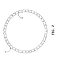
- FIG. 2 is a cross-sectional view of a simplified line drawing of motor housing 12 taken along line 2-2 according to a first embodiment.
- Cooling channels 38 are disposed in motor housing 12. Cooling channels 38 run in an axial direction and parallel to axis 20. Cooling channels 38 provide a heat exchanging function providing for removal of heat created during motor operation.
- FIG. 3 is a cross-sectional view of fan motor assembly 10 according to a second embodiment of the present invention.
- Shaft 18 includes impeller 36 disposed on an upstream end of shaft 18. Impeller 36 is driven by shaft 18. Fins 30b are disposed on a downstream portion of shaft 18. Fins 30b provide an increased surface area from which heat is dissipated from shaft 18 and rotor 16. Impeller 36 pushes passing air 31 through rotor stator gap 26 and across fins 30b resulting in cooling of shaft 18 and rotor 16 through heat exchange. By pushing the passing air through rotor stator gap 26, impeller 36 increases the rate of air flow of passing air 31 throughout fan motor casing assembly 10. Passing air 31 is then directed to cooling channels 38 in fan motor housing 12.
- An increased rate of air flow throughout fan motor casing 10 causes an increase in the amount of passing air 31 that is conductively cooled by main fan flow 29 and motor casing 12.
- the resulting increase in cooling rate of passing air 31 causes fan motor assembly 10 to be cooled at an increased rate.
- Cooling channels extend the length of motor housing 12 in a direction parallel to axis 20. Cooling channels 38 are fluidly connected to rotor stator gap 26. Passing air 31 drawn through rotor stator gap 26 is heated as heat is dissipated from rotor 16 and shaft 18 to passing air 31. Passing air 31 is then directed to cooling channels 38 in motor housing 12. Cooling channels 38 conduct a heat exchanging function providing for removal of heat created during motor operation. Heat from passing air 31 generated during operation is removed by main fan flow 29 over the outer surface of motor housing 12. Passing air 31 from rotor stator gap 26 is directed through cooling channels 38 in an upstream direction to be conductively cooled by main fan flow 29.
- Main fan flow 29 consists of cold exterior air from outside of fan motor assembly 10, and as the cold main fan flow 29 is drawn over motor housing 12, heat is absorbed by main fan flow 29 from motor housing 12. As energy is drawn from motor housing 12 into main fan flow 29, passing air 31 is conductively cooled and is redirected to flow back through rotor stator gap 26 to begin a heat dissipating cycle over again.
- FIG. 4 is a cross-sectional view of a fan motor assembly 10 according to a third embodiment of the present invention.
- Shaft 18 includes impeller 36 disposed on a downstream end of shaft 18. Impeller 36 is driven by shaft 18. Fins 30a are disposed on an upstream portion of shaft 18. Fins 30a provide an increased surface area from which heat is dissipated from shaft 18 and rotor 16. Impeller 36 pull passing air 31 across fins 30a and through rotor stator gap 26 resulting in cooling of shaft 18 and rotor 16 through heat exchange. By pulling passing air 31 through rotor stator gap 26, impeller 36 increases the rate of air flow of passing air 31 throughout fan motor casing assembly 10. Passing air 31 is then directed to cooling channels 38 in fan motor housing 12.
Landscapes
- Engineering & Computer Science (AREA)
- Power Engineering (AREA)
- Motor Or Generator Cooling System (AREA)
- Motor Or Generator Frames (AREA)
Abstract
Description
- The present invention relates to fan motors, and in particular, to a method of cooling fan motors.
- A fan motor includes a stator and a rotor. Heat generated by fan motor operation is traditionally controlled by drawing air from outside the motor to cool the internal components. One method for controlling generated heat is by drawing air through a hollow core shaft to dissipate heat from the shaft to the passing air. Another method draws fresh air from outside the motor and pushes the air through the rotor stator gap. In an additional method, air is drawn through holes in the motor rotor laminations to dissipate heat. Increases in loads and desired power increases heat produced by the motor and therefore require improved methods and structures for removing heat.
- Totally enclosed high power induction or permanent magnet motors used in aircraft fan applications are internal convection cooled. Due to higher power dissipated in new generation of such motors, cooling of the rotor is often challenging, resulting in use of expensive copper rotors, or use of hollow shafts with expensive brazed heat exchangers for cooling such rotors.
- A fan motor assembly comprises a motor housing, a stator, a rotor, a shaft, and a heat exchanger. The stator is located radially inward from the motor housing. The rotor is located radially inward from the stator, and the space between the rotor and stator defining a rotor stator gap. The shaft is located radially inward from and is connected to the rotor. A heat exchanger is mounted on the shaft and extends radially outward form the shaft to transfer heat from the shaft to air drawn through the rotor stator gap.
- Another embodiment is a fan motor assembly which includes a fan casing. A fan impeller is located in an upstream portion of the fan casing. A motor housing is mounted in the fan casing. Fan stator vanes are mounted on the motor housing and extend radially from the housing. A stator is located radially inward from the stator. The stator and the rotor define a rotor stator gap between them. A shaft is located radially inward from the rotor, and the shaft is connected to the rotor. A heat exchanger is mounted on and extends radially outward from the shaft. The heat exchanger is positioned to transfer heat to air drawn through the rotor stator gap.
-
-
FIG. 1 is a cross-sectional view of a fan motor assembly according to a first embodiment of the present invention. -
FIG. 2 is a cross-sectional view of a simplified line drawing of the motor housing shown inFIG. 1 taken along line 2-2 with cooling channels disposed in the motor housing according to a first embodiment of the present invention. -
FIG. 3 is a cross-sectional view of a fan motor assembly according to a second embodiment of the present invention. -
FIG. 4 is a cross-sectional view of a fan motor assembly according to a third embodiment of the present invention. - In this description several methods of cooling such motor are disclosed. These cooling methods utilize the temperature gradient from the rotor to the stator housing surfaces as the driving temperature gradient to remove and dissipate heat from the motor rotor. In this manner of cooling, totally enclosed motors can be cooled very efficiently. Expensive copper rotors and brazed rotor heat exchangers can be eliminated.
-
FIG. 1 is a cross-sectional view offan motor assembly 10 according to a first embodiment of the present invention.FIG. 1 illustratesfan motor assembly 10 which includesmotor housing 12,stator 14,rotor 16, andshaft 18. Within themotor assembly 10,rotor 16 is mounted toshaft 18.Stator 14 defines an inner space within whichrotor 16 andshaft 18 rotate aboutaxis 20. The rotation ofrotor 16 relative to thestationary stator 14 creates an inductive motor function.Stator 14 is spaced radially outward fromrotor 16 such thatrotor stator gap 26 is betweenrotor 16 andstator 14.Stator 14 includesstator core 22 and a plurality ofstator windings 24.Fan impeller 19 is mounted onshaft 18 and rotates to produce amain fan flow 29.Fan stator vanes 28 are disposed radially outward frommotor housing 12. Fan stator vanes 28 directmain fan flow 29 throughfan motor assembly 10 and along the radial exterior ofmotor casing 12. - Due to the relatively fast rotation rates of
rotor 16, over-heating offan motor assembly 10 can become a problem. In order to coolfan motor assembly 10, heat fromrotor 16 is dissipated into passingair 31 located inrotor stator gap 26. Heat from passingair 31 inrotor stator gap 26 is transferred tostator 14. Heat fromstator 14 is conducted tomotor housing 12 where the heat is dissipated bymain fan flow 29 being drawn acrossmotor housing 12. - A multiple of annular heat-radiating fins 30 are mounted on an outer peripheral surface of
shaft 18 axially parallel to each other at regular intervals. Fins 30 are arranged such that their major surfaces are arranged perpendicular toaxis 20 ofshaft 18 so as not to serve as fans. Fins 30 provide increased surface area (e.g., compared to a cylindrical, smooth surface) from whichshaft 18 emits heat into passingair 31. Fins 30 extend radially outward from an outer diameter ofshaft 18. Fins 30 each includefin base 32 andfin end 34. InFIG. 1 ,fin ends 34 have a square profile, however,fin end 34 profiles may alternatively be rounded, tapered, or other shape to achieve a desired cooling effect as described below. A first portion offins 30a are disposed on an upstream segment ofshaft 18 and a second portion offins 30b are disposed on a downstream portion ofshaft 18. - Fins 30 function to cool
fan motor assembly 10 by dissipating heat fromshaft 18 to passingair 31. Passingair 31 is drawn over the surface of fins 30 and heat is dissipated from fins 30 intopassing air 31. By providing an increased surface area ofshaft 18, fms 30 increase the rate of heat dissipation fromshaft 18 to passingair 31. Fins 30 can be formed integrally withshaft 18, such as by machining. Alternatively, fins 30 are formed separately by forming cylindrical laminations and then brazing toshaft 18. If formed separately, fins 30 can be of the same material asshaft 18 or may alternatively be manufactured of a material different thanshaft 18. This provides a benefit of selecting a material that has particularly tailored heat transfer properties, such as a material with a relatively high thermal conductivity. -
FIG. 2 is a cross-sectional view of a simplified line drawing ofmotor housing 12 taken along line 2-2 according to a first embodiment.Cooling channels 38 are disposed inmotor housing 12.Cooling channels 38 run in an axial direction and parallel toaxis 20.Cooling channels 38 provide a heat exchanging function providing for removal of heat created during motor operation. -
FIG. 3 is a cross-sectional view offan motor assembly 10 according to a second embodiment of the present invention.Shaft 18 includesimpeller 36 disposed on an upstream end ofshaft 18.Impeller 36 is driven byshaft 18.Fins 30b are disposed on a downstream portion ofshaft 18.Fins 30b provide an increased surface area from which heat is dissipated fromshaft 18 androtor 16.Impeller 36pushes passing air 31 throughrotor stator gap 26 and acrossfins 30b resulting in cooling ofshaft 18 androtor 16 through heat exchange. By pushing the passing air throughrotor stator gap 26,impeller 36 increases the rate of air flow of passingair 31 throughout fanmotor casing assembly 10. Passingair 31 is then directed to coolingchannels 38 infan motor housing 12. An increased rate of air flow throughoutfan motor casing 10 causes an increase in the amount of passingair 31 that is conductively cooled bymain fan flow 29 andmotor casing 12. The resulting increase in cooling rate of passingair 31 causesfan motor assembly 10 to be cooled at an increased rate. - Cooling channels extend the length of
motor housing 12 in a direction parallel toaxis 20.Cooling channels 38 are fluidly connected torotor stator gap 26. Passingair 31 drawn throughrotor stator gap 26 is heated as heat is dissipated fromrotor 16 andshaft 18 to passingair 31. Passingair 31 is then directed to coolingchannels 38 inmotor housing 12.Cooling channels 38 conduct a heat exchanging function providing for removal of heat created during motor operation. Heat from passingair 31 generated during operation is removed bymain fan flow 29 over the outer surface ofmotor housing 12. Passingair 31 fromrotor stator gap 26 is directed throughcooling channels 38 in an upstream direction to be conductively cooled bymain fan flow 29.Main fan flow 29 consists of cold exterior air from outside offan motor assembly 10, and as the coldmain fan flow 29 is drawn overmotor housing 12, heat is absorbed bymain fan flow 29 frommotor housing 12. As energy is drawn frommotor housing 12 intomain fan flow 29, passingair 31 is conductively cooled and is redirected to flow back throughrotor stator gap 26 to begin a heat dissipating cycle over again. -
FIG. 4 is a cross-sectional view of afan motor assembly 10 according to a third embodiment of the present invention.Shaft 18 includesimpeller 36 disposed on a downstream end ofshaft 18.Impeller 36 is driven byshaft 18.Fins 30a are disposed on an upstream portion ofshaft 18.Fins 30a provide an increased surface area from which heat is dissipated fromshaft 18 androtor 16.Impeller 36pull passing air 31 acrossfins 30a and throughrotor stator gap 26 resulting in cooling ofshaft 18 androtor 16 through heat exchange. By pulling passingair 31 throughrotor stator gap 26,impeller 36 increases the rate of air flow of passingair 31 throughout fanmotor casing assembly 10. Passingair 31 is then directed to coolingchannels 38 infan motor housing 12. An increased rate of air flow throughoutfan motor casing 10 causes an increase in the amount of passingair 31 that is conductively cooled bymain fan flow 29 andmotor casing 12. This combination ofshaft 18,fins 30a,impeller 36, andcooling channels 38 will provide the maximum cooling forfan motor assembly 10. - While the invention has been described with reference to an exemplary embodiment(s), it will be understood by those skilled in the art that various changes may be made and equivalents may be substituted for elements thereof without departing from the scope of the invention. In addition, many modifications may be made to adapt a particular situation or material to the teachings of the invention without departing from the essential scope thereof. Therefore, it is intended that the invention not be limited to the particular embodiment(s) disclosed, but that the invention will include all embodiments falling within the scope of the appended claims.
Claims (14)
- A fan motor assembly (10) comprising:a motor housing (12),a stator (14) located radially inward from the motor housing (12);a rotor (16) located radially inward from the stator (14), the stator (14) and the rotor (16) defining a rotor stator gap (26) there between;a shaft (18) located radially inward from and connected to the rotor (16); anda heat exchanger mounted on and extending radially outward from the shaft (18), the heat exchanger is positioned to transfer heat to air drawn through the rotor stator gap (26).
- The fan motor assembly of any preceding claim further comprising:a fan casing;a fan impeller (36) located in an upstream portion of the fan casing;said motor housing (12) being mounted within the fan casing, with fan stator vanes mounted on and extending radially from the motor housing (12).
- The fan motor assembly of any preceding claim, wherein heat exchanger comprises at least one fin (30).
- The fan motor assembly of claim 3, wherein the at least one fin (30) extends radially outward in a direction generally perpendicular to the shaft (18).
- The fan motor assembly of claim 4, wherein the at least one fin (30) is disposed on a first end of the shaft upstream from the rotor (16).
- The fan motor assembly of claim 4, wherein the at least one fin (30) is disposed on a second end of the shaft downstream from the rotor.
- The fan motor assembly (10) of claim 4, wherein the at least one fin (30) is disposed on at least end of the shaft (18).
- The fan motor assembly (10) of claim 7, wherein air is drawn through the rotor stator gap (26).
- The fan motor assembly of claim 8, wherein an impeller (36) is disposed on a portion of the shaft upstream from the rotor (16).
- The fan motor assembly of claim 8, wherein an impeller (36) is disposed on a portion of the shaft downstream from the rotor (16).
- The fan motor assembly (10) of claim 8, wherein an impeller (36) is disposed the end of the shaft opposite from the at least one fin (30).
- The fan motor assembly (10) of claim 7, wherein the motor housing (12) includes a plurality of cooling channels (38) disposed between a radially outer surface of the motor housing and a radially inner surface of the motor housing, the cooling channels extending in an axial direction parallel to the shaft.
- The fan motor assembly (10) of claim 12, wherein the cooling channels function as heat exchangers for air drawn through the rotor stator gap (26), whereby the air drawn through the rotor stator gap (26) is cooled by a main fan air flow over the outer surface of the motor housing (12).
- The fan motor assembly (10) of claim 1 or 2, wherein the fan motor assembly (10) is totally enclosed.
Applications Claiming Priority (1)
| Application Number | Priority Date | Filing Date | Title |
|---|---|---|---|
| US13/736,523 US9413208B2 (en) | 2013-01-08 | 2013-01-08 | Enhanced cooling of enclosed air cooled high power motors |
Publications (2)
| Publication Number | Publication Date |
|---|---|
| EP2752976A2 true EP2752976A2 (en) | 2014-07-09 |
| EP2752976A3 EP2752976A3 (en) | 2017-04-26 |
Family
ID=49920157
Family Applications (1)
| Application Number | Title | Priority Date | Filing Date |
|---|---|---|---|
| EP14150303.7A Withdrawn EP2752976A3 (en) | 2013-01-08 | 2014-01-07 | Enhanced cooling of enclosed air cooled high power motors |
Country Status (2)
| Country | Link |
|---|---|
| US (1) | US9413208B2 (en) |
| EP (1) | EP2752976A3 (en) |
Cited By (7)
| Publication number | Priority date | Publication date | Assignee | Title |
|---|---|---|---|---|
| CN107040093A (en) * | 2017-06-19 | 2017-08-11 | 东莞质研工业设计服务有限公司 | Servomotor spindle heat abstractor |
| WO2019020684A1 (en) * | 2017-07-26 | 2019-01-31 | Siemens Aktiengesellschaft | ELECTRIC MOTOR WITH COOLING DEVICE |
| EP3667875A1 (en) * | 2018-12-12 | 2020-06-17 | Aurora Flight Sciences Corporation | Motor cooling system and method |
| DE102018132145A1 (en) * | 2018-12-13 | 2020-06-18 | Volocopter Gmbh | Air-cooled electric motor with encapsulated housing |
| EP3742582A1 (en) * | 2019-05-23 | 2020-11-25 | Hamilton Sundstrand Corporation | Electric motor assembly and method |
| US11139722B2 (en) | 2018-03-02 | 2021-10-05 | Black & Decker Inc. | Motor having an external heat sink for a power tool |
| US12054266B2 (en) | 2021-03-29 | 2024-08-06 | Aurora Flight Sciences Corporation | Integrated electric nacelle system and method |
Families Citing this family (8)
| Publication number | Priority date | Publication date | Assignee | Title |
|---|---|---|---|---|
| CN107181366A (en) * | 2017-06-19 | 2017-09-19 | 东莞质研工业设计服务有限公司 | a servo motor |
| CN109149839A (en) * | 2018-08-23 | 2019-01-04 | 浙江东欣节能科技有限公司 | Driving device |
| GB201901557D0 (en) * | 2019-02-05 | 2019-03-27 | Rolls Royce Plc | Matallic shaft |
| US12381442B2 (en) | 2021-02-25 | 2025-08-05 | Regal Beloit America, Inc. | Electric machine assembly |
| WO2024077248A1 (en) | 2022-10-06 | 2024-04-11 | Archer Aviation Inc. | Systems, methods, and mechanical designs for inverters for evtol aircraft |
| US12312091B2 (en) | 2022-10-06 | 2025-05-27 | Archer Aviation Inc. | Systems and methods for improved gearboxes for evtol aircraft |
| US11787551B1 (en) | 2022-10-06 | 2023-10-17 | Archer Aviation, Inc. | Vertical takeoff and landing aircraft electric engine configuration |
| US12227300B2 (en) | 2022-10-06 | 2025-02-18 | Archer Aviation Inc. | Systems and methods for oil maintenance in gearboxes for eVTOL aircraft |
Citations (5)
| Publication number | Priority date | Publication date | Assignee | Title |
|---|---|---|---|---|
| US3916231A (en) * | 1973-12-26 | 1975-10-28 | Marathon Letourneau Co | Induction motor |
| DE102004047735A1 (en) * | 2004-09-30 | 2006-04-13 | Siemens Ag | Electrical machine especially closed machine has rotor with axial air cooling channels and suction channels cooling between shorting ring and sheet packet |
| US20090230791A1 (en) * | 2005-09-29 | 2009-09-17 | Zf Friedrichshafen Ag | Drive unit having optimized cooling |
| JP2011036104A (en) * | 2009-08-05 | 2011-02-17 | Fuji Electric Systems Co Ltd | Permanent magnet type rotary electric machine |
| DE102011003597A1 (en) * | 2011-02-03 | 2012-08-09 | Siemens Aktiengesellschaft | Electrical machine has housing have inlet and exit side recesses so that cooling medium radially enters into inlet-side recess and axially flows to outlet-side recess through cooling channels and radially discharges from outlet-side recess |
Family Cites Families (22)
| Publication number | Priority date | Publication date | Assignee | Title |
|---|---|---|---|---|
| US2630676A (en) * | 1947-01-20 | 1953-03-10 | Donald W Seifert | Axial flow jet motor with rotating combustion products generator and turbine |
| JPS5367015U (en) * | 1976-11-10 | 1978-06-06 | ||
| JPS5471304A (en) * | 1977-11-17 | 1979-06-07 | Fujitsu Fanuc Ltd | Revolving electric machine with heat pipe for cooling |
| JPS5577351A (en) * | 1978-12-06 | 1980-06-11 | Fuji Electric Co Ltd | Heat pipe cooling system for rotary machine |
| JPS576553A (en) * | 1980-06-12 | 1982-01-13 | Fanuc Ltd | Motor |
| JP3253709B2 (en) * | 1992-12-02 | 2002-02-04 | 株式会社東芝 | Fully enclosed fan-type rotating electric machine |
| IT1264747B1 (en) | 1993-12-10 | 1996-10-04 | Ima Spa | ROTARY COMPRESSING MACHINE |
| JP2966799B2 (en) | 1996-11-07 | 1999-10-25 | ファナック株式会社 | Air-cooled motor |
| US6774514B2 (en) | 2000-02-25 | 2004-08-10 | Kabushiki Kaisha Toshiba | Totally enclosed type driving electric motor |
| US6914355B2 (en) * | 2002-12-19 | 2005-07-05 | Honeywell International Inc. | Common radial plane motor cooling |
| DE10261572A1 (en) * | 2002-12-23 | 2004-07-01 | Robert Bosch Gmbh | Electric hand tool machine e.g. drill, has arrangement for generating additional cooling air flow that passes at least one machine component outside or in low flow region of cooling air flow |
| JP2007306741A (en) * | 2006-05-12 | 2007-11-22 | Toshiba Corp | Control device integrated motor |
| JP2007318885A (en) * | 2006-05-25 | 2007-12-06 | Mabuchi Motor Co Ltd | Brushless motor |
| US7541701B2 (en) * | 2006-06-07 | 2009-06-02 | A.O. Smith Corporation | Totally enclosed fan cooled motor |
| DE102007034013A1 (en) * | 2007-07-20 | 2009-01-29 | Wacker Construction Equipment Ag | Working machine for an internal vibrator |
| US7736062B2 (en) * | 2007-09-14 | 2010-06-15 | Hamilton Sundstrand Corporation | Auxiliary rotary bearing system |
| US8053938B2 (en) | 2007-11-09 | 2011-11-08 | Hamilton Sundstand Corporation | Enhanced motor cooling system |
| FR2929772B1 (en) * | 2008-04-08 | 2016-01-15 | Leroy Somer Moteurs | ELECTRIC MACHINE COMPRISING A MULTI-CHANNEL FAN |
| WO2010097837A1 (en) * | 2009-02-27 | 2010-09-02 | 株式会社日立製作所 | Permanent magnet generator |
| JP4884515B2 (en) * | 2009-10-30 | 2012-02-29 | 三菱電機株式会社 | Brushless rotating electric machine |
| JP4787351B2 (en) * | 2009-11-09 | 2011-10-05 | ファナック株式会社 | Induction motor with a heat dissipation disk that dissipates heat generated in the rotor |
| US8587165B2 (en) * | 2011-03-30 | 2013-11-19 | Dayton-Phoenix Group, Inc. | Cooled fan motor and method of operation |
-
2013
- 2013-01-08 US US13/736,523 patent/US9413208B2/en active Active
-
2014
- 2014-01-07 EP EP14150303.7A patent/EP2752976A3/en not_active Withdrawn
Patent Citations (5)
| Publication number | Priority date | Publication date | Assignee | Title |
|---|---|---|---|---|
| US3916231A (en) * | 1973-12-26 | 1975-10-28 | Marathon Letourneau Co | Induction motor |
| DE102004047735A1 (en) * | 2004-09-30 | 2006-04-13 | Siemens Ag | Electrical machine especially closed machine has rotor with axial air cooling channels and suction channels cooling between shorting ring and sheet packet |
| US20090230791A1 (en) * | 2005-09-29 | 2009-09-17 | Zf Friedrichshafen Ag | Drive unit having optimized cooling |
| JP2011036104A (en) * | 2009-08-05 | 2011-02-17 | Fuji Electric Systems Co Ltd | Permanent magnet type rotary electric machine |
| DE102011003597A1 (en) * | 2011-02-03 | 2012-08-09 | Siemens Aktiengesellschaft | Electrical machine has housing have inlet and exit side recesses so that cooling medium radially enters into inlet-side recess and axially flows to outlet-side recess through cooling channels and radially discharges from outlet-side recess |
Cited By (12)
| Publication number | Priority date | Publication date | Assignee | Title |
|---|---|---|---|---|
| CN107040093A (en) * | 2017-06-19 | 2017-08-11 | 东莞质研工业设计服务有限公司 | Servomotor spindle heat abstractor |
| WO2019020684A1 (en) * | 2017-07-26 | 2019-01-31 | Siemens Aktiengesellschaft | ELECTRIC MOTOR WITH COOLING DEVICE |
| US11271455B2 (en) | 2017-07-26 | 2022-03-08 | Rolls-Royce Deutschland Ltd & Co Kg | Electric motor having a cooling device |
| US11139722B2 (en) | 2018-03-02 | 2021-10-05 | Black & Decker Inc. | Motor having an external heat sink for a power tool |
| EP3667875A1 (en) * | 2018-12-12 | 2020-06-17 | Aurora Flight Sciences Corporation | Motor cooling system and method |
| CN111301692A (en) * | 2018-12-12 | 2020-06-19 | 欧若拉飞行科学公司 | Motor cooling system and method |
| US11387693B2 (en) | 2018-12-12 | 2022-07-12 | Aurora Flight Sciences Corporation | Motor cooling system and method |
| CN111301692B (en) * | 2018-12-12 | 2024-05-14 | 欧若拉飞行科学公司 | Motor cooling system and method |
| DE102018132145A1 (en) * | 2018-12-13 | 2020-06-18 | Volocopter Gmbh | Air-cooled electric motor with encapsulated housing |
| EP3742582A1 (en) * | 2019-05-23 | 2020-11-25 | Hamilton Sundstrand Corporation | Electric motor assembly and method |
| US11245307B2 (en) | 2019-05-23 | 2022-02-08 | Hamilton Sundstrand Corporation | Electric motor assembly |
| US12054266B2 (en) | 2021-03-29 | 2024-08-06 | Aurora Flight Sciences Corporation | Integrated electric nacelle system and method |
Also Published As
| Publication number | Publication date |
|---|---|
| US20140191597A1 (en) | 2014-07-10 |
| EP2752976A3 (en) | 2017-04-26 |
| US9413208B2 (en) | 2016-08-09 |
Similar Documents
| Publication | Publication Date | Title |
|---|---|---|
| US9413208B2 (en) | Enhanced cooling of enclosed air cooled high power motors | |
| CN103026597B (en) | Fluid-cooled motor | |
| US20170237316A1 (en) | Rotor Shaft Arrangement and Method for Manufacturing the Same | |
| EP2787609B1 (en) | Motor cooling apparatus and method | |
| US11387725B2 (en) | Integrated heat dissipative structure for electric machine | |
| EP3487042B1 (en) | Electric motor | |
| CN107925305B (en) | Cooling systems for electric machines | |
| CN101517865A (en) | Electrical machine with an internally cooled rotor | |
| CN105322674A (en) | Generator armature | |
| EP2383867B1 (en) | Electric machine | |
| Karnavas et al. | Cooling system design and thermal analysis of an electric vehicle's in-wheel PMSM | |
| WO2018196003A1 (en) | Motor ventilation structure and motor | |
| RU2695320C1 (en) | Combined cooling system of closed inductor machine | |
| EP2662952B1 (en) | Generator, in particular for a wind turbine | |
| US20250158488A1 (en) | Enhanced convective rotor cooling | |
| CN102447322B (en) | Electromotor, especially for the electromotor of wind turbine | |
| CN103959615B (en) | Including the vehicle drive assembly cooled down by means of heat-transfer fluid and lubricating fluid | |
| CN104145405B (en) | Housing for open drip proof type electric rotating machine | |
| EP2899850B1 (en) | Electric generator for a wind turbine with stator gaps varying in axial direction of the generator | |
| US20180175702A1 (en) | Motor shaft system with a cooling function | |
| EP2595283B1 (en) | Heat transfer assembly for electric motor rotor | |
| CN215580591U (en) | Rotor subassembly and have its motor | |
| CN206099617U (en) | Motor frame with cooling channels | |
| JP2020178380A (en) | Rotor and electric motor | |
| CN111130305A (en) | Speed regulation type magnetic coupler of outer cage type rotor of no end ring |
Legal Events
| Date | Code | Title | Description |
|---|---|---|---|
| 17P | Request for examination filed |
Effective date: 20140107 |
|
| AK | Designated contracting states |
Kind code of ref document: A2 Designated state(s): AL AT BE BG CH CY CZ DE DK EE ES FI FR GB GR HR HU IE IS IT LI LT LU LV MC MK MT NL NO PL PT RO RS SE SI SK SM TR |
|
| AX | Request for extension of the european patent |
Extension state: BA ME |
|
| PUAI | Public reference made under article 153(3) epc to a published international application that has entered the european phase |
Free format text: ORIGINAL CODE: 0009012 |
|
| PUAL | Search report despatched |
Free format text: ORIGINAL CODE: 0009013 |
|
| RIC1 | Information provided on ipc code assigned before grant |
Ipc: H02K 9/18 20060101ALI20170316BHEP Ipc: H02K 9/06 20060101AFI20170316BHEP Ipc: H02K 9/22 20060101ALI20170316BHEP |
|
| AK | Designated contracting states |
Kind code of ref document: A3 Designated state(s): AL AT BE BG CH CY CZ DE DK EE ES FI FR GB GR HR HU IE IS IT LI LT LU LV MC MK MT NL NO PL PT RO RS SE SI SK SM TR |
|
| AX | Request for extension of the european patent |
Extension state: BA ME |
|
| STAA | Information on the status of an ep patent application or granted ep patent |
Free format text: STATUS: REQUEST FOR EXAMINATION WAS MADE |
|
| STAA | Information on the status of an ep patent application or granted ep patent |
Free format text: STATUS: EXAMINATION IS IN PROGRESS |
|
| R17P | Request for examination filed (corrected) |
Effective date: 20171025 |
|
| RBV | Designated contracting states (corrected) |
Designated state(s): AL AT BE BG CH CY CZ DE DK EE ES FI FR GB GR HR HU IE IS IT LI LT LU LV MC MK MT NL NO PL PT RO RS SE SI SK SM TR |
|
| 17Q | First examination report despatched |
Effective date: 20171128 |
|
| STAA | Information on the status of an ep patent application or granted ep patent |
Free format text: STATUS: THE APPLICATION HAS BEEN WITHDRAWN |
|
| 18W | Application withdrawn |
Effective date: 20230620 |