EP2752887A1 - Method for producing solar cell module - Google Patents
Method for producing solar cell module Download PDFInfo
- Publication number
- EP2752887A1 EP2752887A1 EP11871746.1A EP11871746A EP2752887A1 EP 2752887 A1 EP2752887 A1 EP 2752887A1 EP 11871746 A EP11871746 A EP 11871746A EP 2752887 A1 EP2752887 A1 EP 2752887A1
- Authority
- EP
- European Patent Office
- Prior art keywords
- wiring member
- connection step
- wiring
- electrode
- solar cell
- Prior art date
- Legal status (The legal status is an assumption and is not a legal conclusion. Google has not performed a legal analysis and makes no representation as to the accuracy of the status listed.)
- Withdrawn
Links
- 238000004519 manufacturing process Methods 0.000 title claims abstract description 21
- 229920005989 resin Polymers 0.000 claims abstract description 36
- 239000011347 resin Substances 0.000 claims abstract description 36
- 239000000853 adhesive Substances 0.000 claims abstract description 23
- 230000001070 adhesive effect Effects 0.000 claims abstract description 23
- 238000000034 method Methods 0.000 claims abstract description 14
- 238000010438 heat treatment Methods 0.000 claims abstract description 13
- 239000010410 layer Substances 0.000 description 8
- 229910052751 metal Inorganic materials 0.000 description 6
- 239000002184 metal Substances 0.000 description 6
- 239000010408 film Substances 0.000 description 4
- 239000000463 material Substances 0.000 description 4
- 239000004065 semiconductor Substances 0.000 description 3
- 239000012790 adhesive layer Substances 0.000 description 2
- 239000000956 alloy Substances 0.000 description 2
- 229910045601 alloy Inorganic materials 0.000 description 2
- 229910052802 copper Inorganic materials 0.000 description 2
- 230000000694 effects Effects 0.000 description 2
- 239000011521 glass Substances 0.000 description 2
- 229910052737 gold Inorganic materials 0.000 description 2
- 150000002739 metals Chemical class 0.000 description 2
- 229920003023 plastic Polymers 0.000 description 2
- 239000004033 plastic Substances 0.000 description 2
- 229910052697 platinum Inorganic materials 0.000 description 2
- 229920002037 poly(vinyl butyral) polymer Polymers 0.000 description 2
- 229910052709 silver Inorganic materials 0.000 description 2
- 229910052718 tin Inorganic materials 0.000 description 2
- 229910010293 ceramic material Inorganic materials 0.000 description 1
- 230000007613 environmental effect Effects 0.000 description 1
- 239000005038 ethylene vinyl acetate Substances 0.000 description 1
- 239000011888 foil Substances 0.000 description 1
- 239000012212 insulator Substances 0.000 description 1
- 230000002093 peripheral effect Effects 0.000 description 1
- 238000007789 sealing Methods 0.000 description 1
- 239000010409 thin film Substances 0.000 description 1
Images


Classifications
-
- H—ELECTRICITY
- H01—ELECTRIC ELEMENTS
- H01R—ELECTRICALLY-CONDUCTIVE CONNECTIONS; STRUCTURAL ASSOCIATIONS OF A PLURALITY OF MUTUALLY-INSULATED ELECTRICAL CONNECTING ELEMENTS; COUPLING DEVICES; CURRENT COLLECTORS
- H01R43/00—Apparatus or processes specially adapted for manufacturing, assembling, maintaining, or repairing of line connectors or current collectors or for joining electric conductors
- H01R43/26—Apparatus or processes specially adapted for manufacturing, assembling, maintaining, or repairing of line connectors or current collectors or for joining electric conductors for engaging or disengaging the two parts of a coupling device
-
- H—ELECTRICITY
- H10—SEMICONDUCTOR DEVICES; ELECTRIC SOLID-STATE DEVICES NOT OTHERWISE PROVIDED FOR
- H10F—INORGANIC SEMICONDUCTOR DEVICES SENSITIVE TO INFRARED RADIATION, LIGHT, ELECTROMAGNETIC RADIATION OF SHORTER WAVELENGTH OR CORPUSCULAR RADIATION
- H10F19/00—Integrated devices, or assemblies of multiple devices, comprising at least one photovoltaic cell covered by group H10F10/00, e.g. photovoltaic modules
- H10F19/90—Structures for connecting between photovoltaic cells, e.g. interconnections or insulating spacers
- H10F19/902—Structures for connecting between photovoltaic cells, e.g. interconnections or insulating spacers for series or parallel connection of photovoltaic cells
- H10F19/904—Structures for connecting between photovoltaic cells, e.g. interconnections or insulating spacers for series or parallel connection of photovoltaic cells characterised by the shapes of the structures
-
- H—ELECTRICITY
- H10—SEMICONDUCTOR DEVICES; ELECTRIC SOLID-STATE DEVICES NOT OTHERWISE PROVIDED FOR
- H10F—INORGANIC SEMICONDUCTOR DEVICES SENSITIVE TO INFRARED RADIATION, LIGHT, ELECTROMAGNETIC RADIATION OF SHORTER WAVELENGTH OR CORPUSCULAR RADIATION
- H10F19/00—Integrated devices, or assemblies of multiple devices, comprising at least one photovoltaic cell covered by group H10F10/00, e.g. photovoltaic modules
- H10F19/90—Structures for connecting between photovoltaic cells, e.g. interconnections or insulating spacers
- H10F19/902—Structures for connecting between photovoltaic cells, e.g. interconnections or insulating spacers for series or parallel connection of photovoltaic cells
- H10F19/906—Structures for connecting between photovoltaic cells, e.g. interconnections or insulating spacers for series or parallel connection of photovoltaic cells characterised by the materials of the structures
-
- Y—GENERAL TAGGING OF NEW TECHNOLOGICAL DEVELOPMENTS; GENERAL TAGGING OF CROSS-SECTIONAL TECHNOLOGIES SPANNING OVER SEVERAL SECTIONS OF THE IPC; TECHNICAL SUBJECTS COVERED BY FORMER USPC CROSS-REFERENCE ART COLLECTIONS [XRACs] AND DIGESTS
- Y02—TECHNOLOGIES OR APPLICATIONS FOR MITIGATION OR ADAPTATION AGAINST CLIMATE CHANGE
- Y02E—REDUCTION OF GREENHOUSE GAS [GHG] EMISSIONS, RELATED TO ENERGY GENERATION, TRANSMISSION OR DISTRIBUTION
- Y02E10/00—Energy generation through renewable energy sources
- Y02E10/50—Photovoltaic [PV] energy
-
- Y—GENERAL TAGGING OF NEW TECHNOLOGICAL DEVELOPMENTS; GENERAL TAGGING OF CROSS-SECTIONAL TECHNOLOGIES SPANNING OVER SEVERAL SECTIONS OF THE IPC; TECHNICAL SUBJECTS COVERED BY FORMER USPC CROSS-REFERENCE ART COLLECTIONS [XRACs] AND DIGESTS
- Y10—TECHNICAL SUBJECTS COVERED BY FORMER USPC
- Y10T—TECHNICAL SUBJECTS COVERED BY FORMER US CLASSIFICATION
- Y10T29/00—Metal working
- Y10T29/49—Method of mechanical manufacture
- Y10T29/49002—Electrical device making
- Y10T29/49117—Conductor or circuit manufacturing
- Y10T29/49174—Assembling terminal to elongated conductor
- Y10T29/49176—Assembling terminal to elongated conductor with molding of electrically insulating material
Definitions
- the present invention relates to a manufacturing method for a solar module.
- Patent Document 1 Solar modules in which a plurality of solar cells is connected electrically have attracted much attention in recent years as an energy source with a low environmental impact.
- a solar module including back contact solar cells has been disclosed in Patent Document 1.
- the wiring member has a plurality of wires, and the p-side electrode of one solar cell is connected electrically to the n-side electrode of an adjacent solar cell using said wires.
- Patent Document 1 describes the bonding of the wiring member to solar cells using anisotropically conductive film.
- Patent Document 1 Laid-Open Patent Publication No. 2009-266848
- Patent Document 1 There is room for improving the method of adhering a solar cell to a wiring member described in Patent Document 1.
- the method for manufacturing a solar module includes a first connection step.
- a wiring member is connected to a first electrode arranged on the back surface of a first solar cell.
- the first connection step includes a step of arranging the wiring member on the first electrode with a resin adhesive interposed between them, and a step of heating the wiring member while applying relative pressure on the first electrode side.
- the heating step is performed separately in a plurality of areas.
- the present invention is able to provide a method for manufacturing a solar module in which it is possible to electrically connect a wiring member and a solar cell in an advantageous manner.
- the solar cells 1 shown in FIG. 1 and the wiring member 2 shown in FIG. 2 are prepared. There are no particular restrictions on the type of solar cell 1.
- the solar cells 1 can be made, for example, using any type of semiconductor material such as a crystalline semiconductor or a thin-film semiconductor.
- the solar cells 1 are back contact solar cells.
- the solar cells 1 have a light-receiving surface (not shown) and a back surface 1b, and the back surface 1b has first and second electrodes 11 and 12.
- One of the first and second electrodes 11, 12 is an electrode that collects holes, and the other is an electrode that collects electrons.
- the first electrode 11 has a plurality of first finger portions 11a.
- the second electrode 12 has a plurality of second finger portions 12a. More specifically, the first electrode 11 is a busbarless electrode that includes a plurality of first finger portions 11a but no busbar portion.
- the second electrode 12 is also a busbarless electrode that includes a plurality of second finger portions 12a but no busbar portion.
- Each of the first finger portions 11a constituting the first electrode 11 extends in the y-direction, or the first direction, so as to be oriented from one end to the other in the y-direction.
- the first finger portions 11a are arranged at predetermined intervals in the x-direction, or the second direction, which intersects the y-direction.
- Each of the second finger portions 12a constituting the second electrode 12 extends in the y-direction, so as to be oriented from one end to the other in the y-direction.
- the second finger portions 12a are arranged at predetermined intervals in the x-direction.
- the first finger portions 11a and the second finger portions 12a are interdigitated in the x-direction.
- the first and second electrodes 11, 12 can be made of a suitably conductive member.
- the first and second electrodes 11, 12 can be made of a metal such as Ag, Cu, Au, Pt or Sn, or from an alloy including at least one of these metals.
- One or both of the first and second electrodes 11, 12 can be a stacked body composed of a plurality of conductive layers.
- the wiring member 2 is used to electrically connect a plurality of solar cells 1.
- the wiring member 2 has a length in the x-direction that covers all of the first finger portions 11a.
- the wiring member 2 also has a length in the x-direction that covers all of the second finger portions 12a.
- the wiring member 2 has a wiring member main body 20 and wiring 21. There are no particular restrictions on the material used to form the wiring member main body as long as the material is an insulator.
- the wiring member main body 20, for example, can be made of a ceramic material or a resin material.
- the wiring member main body 20 is preferably made of a resin because it is easier to manufacture.
- the wiring 21 is arranged on the wiring member main body 20.
- the entirety of the wiring does not have to be arranged on the wiring member main body.
- Some of the wiring may be arranged inside of the wiring member main body.
- the wiring 21 can be made of a suitably conductive member.
- the wiring 21 can be made of a metal such as Ag, Cu, Au, Pt or Sn, or from an alloy including at least one of these metals.
- the wiring 21 has a plurality of first linear portions 21a, a plurality of second linear portions 21 b, and a connecting portion 21c.
- the first linear portions 21a and second linear portions 21b are connected electrically to the connecting portion 21c.
- Each of the first linear portions 21a extends in the y-direction from the connecting portion 21c towards the y1 side (the one side in the first direction).
- the first linear portions 21a are connected electrically to the first finger portions 11a of the solar cell 1, and are provided so as to correspond to the first finger portions 11a. In other words, the first linear portions 21a are arranged at intervals in the x-direction at the same pitch as the first finger portions 11a.
- Each of the second linear portions 21b extends in the y-direction from the connecting portion 21c towards the y2 side (the other side in the first direction).
- the second linear portions 21b are connected electrically to the second finger portions 12a of the solar cell 1, and are provided so as to correspond to the second finger portions 12a.
- the second linear portions 21b are arranged at intervals in the x-direction at the same pitch as the second finger portions 12a.
- a plurality of solar cells 1 is connected electrically using a wiring member 2 to produce a solar cell string having a plurality of solar cells 1 connected electrically by a wiring member 2.
- the wiring 21 of the wiring member 2 is connected electrically to the first finger portions 11a of the first electrode 11 in one solar cell (the first solar cell) 1A and the second finger portions 12a of the second electrode 12 of another solar cell (the second solar cell) 1B (connection step). This step is repeated to produce a solar cell string.
- resin adhesive 31 is arranged between the wiring member 2 and solar cell 1A, heat and relative pressure are applied, and the resin adhesive 31 is thermocured to bond the wiring member 2 to the solar cell 1A and electrically connect the first linear portions 21a of the wiring member 2 to the first finger portions 11a of the solar cell 1A.
- resin adhesive 31 is arranged between the wiring member 2 and solar cell 1B, heat and relative pressure are applied, and the resin adhesive 31 is thermocured to bond the wiring member 2 to the solar cell 1B and electrically connect the second linear portions 21b of the wiring member 2 to the second finger portions 12b of the solar cell 1B.
- the solar cells 1A, 1B are bonded to the wiring member 2 via an adhesive layer 30 including the cured resin adhesive 31.
- the resin adhesive 31 has insulating or conductive properties.
- the main component of the resin adhesive 31 is an insulating resin, and the resin adhesive contains a conductive member inside.
- the wiring member 2 and solar cell 1A are preferably bonded such that the first linear portions 21a of the wiring member 2 and the first finger portions 11a of the solar cell 1A are in direct contact with each other.
- the wiring member 2 and solar cell 1B are preferably bonded such that the second linear portions 21b of the wiring member 2 and the second finger portions 12a of the solar cell 1B are in direct contact with each other.
- the first finger portions 11a and the first linear portions 21a may be in direct electrical contact with each other or in indirect electrical contact via the conductive member.
- the second portions 12a and the second linear portions 21b may be in direct electrical contact with each other or in indirect electrical contact via the conductive member.
- the size and concentration of the conductive member is adjusted so that undesired electrical contact does not occur via the conductive member. In other words, it is adjusted so that electrical contact does not occur between the first finger portions 11a and the second finger portions 12a via the conductive member, electrical contact does not occur between the first linear portions 21a and the second finger portions 12a via the conductive member, and electrical contact does not occur between the second linear portions 21b and the first finger portions 11a via the conductive member.
- the conductive member is preferably an anisotropically conductive film or a resin adhesive with anisotropic conductive properties such as an anisotropically conductive paste.
- connection step heat and pressure are applied to the wiring member 2 and the solar cell 1A separately in each of a plurality of areas A1-A4 arranged in the x-direction, or the second direction.
- connection step there is a step in which heat and pressure is applied to one of the areas A1-A4 using a heated bonding tool 41, and a step in which the bonding tool 41 is moved in the x-direction.
- the bonding tool 41 is moved in the x-direction.
- the heat and pressure step is performed in the same manner between the wiring member 2 and solar cell 1B. There is actually a pair of bonding tools 41 above and below the solar cell.
- the bonding tool 41 has a width that spans at least one first finger portion 11a and one second finger portion 12a (lengthwise in the x-direction). As seen in FIG. 3 , the bonding tool 41 has a length which is at least approximately the same as that of the wiring member 2 (lengthwise in the y-direction).
- a first solar cell 1A and a second solar cell 1B are arranged adjacent to each other.
- a resin adhesive 31 is interposed, and a wiring member 20 is arranged so as to span a side edge of the first solar cell 1A and a side edge of the second solar cell 1B.
- heat and pressure are applied to area A1 using a heated bonding tool 41 to bond the wiring member 2 to the solar cells 1A, 1B in area A1.
- the first linear portions 21a and the first finger portions 11a are connected electrically
- the second linear portions 22a and the second finger portion 12a are connected electrically in area A1.
- the heating tool 41 is moved to area A2 in the x-direction.
- heat and pressure are applied to area A2 using a heated bonding tool 41 to bond the wiring member 2 to the solar cells 1A, 1B in area A2. Afterwards, the heating tool 41 is moved to area A3 in the x-direction. Next, heat and pressure are applied to area A3 using a heated bonding tool 41 to bond the wiring member 2 to the solar cells 1A, 1B in area A3. Afterwards, the heating tool 41 is moved to area A4 in the x-direction. Next, heat and pressure are applied to area A4 using a heated bonding tool 41 to bond the wiring member 2 to the solar cells 1A, 1B in area A4. Heat and pressure are applied four times to bond the wiring member 2 to the solar cells 1A, 1B. In addition, the first linear portions 21a and the first finger portions 11a are connected electrically, and the second linear portions 22a and the second finger portion 12a are connected electrically.
- the solar cell string is sealed between a first protecting member 4 and a second protecting member 5 using a bonding layer 6.
- a resin sheet constituting the light-receiving side of the bonding layer 6 is arranged on the second protecting member 5.
- the solar cell string is then arranged on the resin sheet.
- a resin sheet constituting the back side of the bonding layer 6 is arranged thereon, and then the first protecting member 4 is arranged on top.
- the second protecting member 5 can be made of a translucent member such as translucent glass or plastic. Light is incident on the solar module 3 from the side with the second protecting member 5.
- the first protecting member 4 can be a weather-resistant member made of translucent glass or plastic, resin film, or resin film containing an interposed layer of metal foil.
- the bonding layer 6 can be made of a resin such as an ethylene-vinylacetate (EVA) copolymer or polyvinyl butyral (PVB).
- EVA ethylene-vinylacetate
- PVB polyvinyl butyral
- a terminal box may be arranged on the first protecting member 4 to extract electrical power generated by the solar cells 1.
- a metal or resin frame may be provided on the peripheral edges of the solar module 3.
- the wiring member and the solar cells have different thermal expansion coefficients.
- the thermal expansion coefficient of the wiring member is higher than that of the solar cells. Therefore, when heat and pressure are applied to the wiring member and the solar cells all at once, the wiring member expands more than the solar cells. As a result, the wiring in the wiring member and the electrodes in the solar cells become misaligned, and the wiring and electrodes are often not connected very well electrically.
- heat and pressure are applied to the wiring member 2 and the solar cells 1A, 1B in the connection step separately in each of a plurality of areas A1-A4 in the x-direction or second direction.
- the difference in the amount of thermal expansion by the wiring member 2 and the amount of thermal expansion by the solar cells 1A, 1B is small because the area of the wiring member 2 and the solar cells 1A, 1B heated all at once is small.
- any misalignment between the wiring 21 in the wiring member 2 and the electrodes 11, 12 in the solar cells 1A, 1B can be suppressed.
- the wiring 21 and the electrodes 11, 12 are connected electrically in an advantageous manner. Therefore, a solar module 3 with improved reliability and output characteristics can be manufactured.
- the difference in the amount of thermal expansion by the wiring member 2 and the amount of thermal expansion by the solar cells 1A, 1B in the connection step is small, the residual stress generated in the wiring member 2 and the solar cells 1A, 1B can also be reduced. This can suppress peeling of the wiring member 2 from the solar cells 1A, 1B and warping of the solar cells 1A, 1B.
- the thermal expansion coefficient of the wiring member 2 is greater relative to the solar cells 1. Therefore, misalignment of the electrodes and wiring is more likely to occur. Peeling of the wiring member 2 and warping of the solar cells 1 are also more likely to occur. Thus, it is especially advantageous in these circumstances to apply heat and pressure separately to each of a plurality of areas A1-A4.
- connection step was performed using a single pair of bonding tools 41.
- the connection step is performed using several pairs of bonding tools 41a-41d. More specifically, in the connection step, there is a first connection step in which a pair of bonding tools 41 a-41 d provided in each of the areas A1-A4 is used to apply pressure to the wiring member 2 and the solar cells 1A, 1B while the temperature is raised in at least one of the pairs of bonding tools 41 a-41 d above the curing temperature at which the resin adhesive 31 is cured, and a second connection step in which the temperature is raised above the curing temperature in at least one of the remaining pairs of bonding tools 41a-41d after the first connection step.
- the temperature of the bonding tools other than those which have been raised above the curing temperature is preferably maintained at a temperature below the curing temperature.
- pressure is first applied to the wiring member 2 and the solar cells 1A, 1B using the plurality of bonding tools 41a-41d provided in each of the areas A1-A4.
- the temperature of the bonding tools 4 1 a, 4 1 d positioned on both ends in the x-direction is raised above the curing temperature.
- the resin adhesive 31 is cured and the wiring member 2 is bonded to the solar cells 1A, 1B in areas A1 and A4.
- the temperature of bonding tools 41b and 41c are maintained at a temperature below the curing temperature.
- the temperature of the bonding tools 41b, 41c positioned in the center in the x-direction is raised above the curing temperature.
- the resin adhesive 31 is cured and the wiring member 2 is bonded to the solar cells 1A, 1B in areas A2 and A3.
- the temperature of bonding tools 41a and 41d are maintained at a temperature below the curing temperature.
- either one of the first and second electrodes may have a busbar portion to which the finger portions are connected electrically.
- the solar cells were divided into four areas, and heat and pressure were applied to each of the areas.
- the present invention is not restricted to this number of areas.
- the present invention is not restricted to a certain number of applications of heat and pressure.
- heat and pressure may be applied two separate times.
- heat and pressure may be applied to each area in which finger portions have been provided.
- heat and pressure were applied to the central areas A2, A3 in the second direction (x-direction) after heat and pressure were applied to the areas A1, A4 on both ends in the second direction (x-direction).
- heat and pressure may be applied in the x-direction to area A1, area A2, area A3 and area A4 in sequential order.
- heat and pressure may be applied simultaneously to areas A3 and A4 after heat and pressure has been applied simultaneously to areas A1 and A2.
Landscapes
- Engineering & Computer Science (AREA)
- Manufacturing & Machinery (AREA)
- Photovoltaic Devices (AREA)
Abstract
Provided is a method for manufacturing a solar module in which it is possible to electrically connect a wiring member and a solar cell in an advantageous manner. A first connection step is performed in which a wiring member (2) is connected to a first electrode (11) arranged on the back surface of a first solar cell (1). The first connection step includes a step of arranging the wiring member (2) on the first electrode (11) with a resin adhesive (31) interposed therebetween, and a step of heating the wiring member (2) while applying relative pressure on the first electrode (11) side. The heating step is performed separately in a plurality of areas (A1-A4).
Description
- The present invention relates to a manufacturing method for a solar module.
- Solar modules in which a plurality of solar cells is connected electrically have attracted much attention in recent years as an energy source with a low environmental impact. A solar module including back contact solar cells has been disclosed in
Patent Document 1. In the solar module described inPatent Document 1, the wiring member has a plurality of wires, and the p-side electrode of one solar cell is connected electrically to the n-side electrode of an adjacent solar cell using said wires.Patent Document 1 describes the bonding of the wiring member to solar cells using anisotropically conductive film. - Patent Document 1: Laid-Open Patent Publication No.
2009-266848 - There is room for improving the method of adhering a solar cell to a wiring member described in
Patent Document 1. - It is a main object of the present invention to provide a method for manufacturing a solar module in which it is possible to electrically connect a wiring member and a solar cell in an advantageous manner.
- In the present invention, the method for manufacturing a solar module includes a first connection step. In the first connection step, a wiring member is connected to a first electrode arranged on the back surface of a first solar cell. The first connection step includes a step of arranging the wiring member on the first electrode with a resin adhesive interposed between them, and a step of heating the wiring member while applying relative pressure on the first electrode side. The heating step is performed separately in a plurality of areas.
- The present invention is able to provide a method for manufacturing a solar module in which it is possible to electrically connect a wiring member and a solar cell in an advantageous manner.
-
-
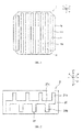
FIG. 1 is a simplified rear view of a solar cell in a first embodiment. -
FIG. 2 is a simplified rear view of a wiring member in the first embodiment. -
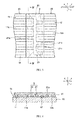
FIG. 3 is a simplified rear view used to explain the manufacturing process for a solar module in the first embodiment. -
FIG. 4 is a simplified cross-sectional view from line IV-IV inFIG. 3 . -
FIG. 5 is a simplified cross-sectional view used to explain the manufacturing process for a solar module in the first embodiment. -
FIG. 6 is a simplified cross-sectional view of the solar module manufactured in the first embodiment. -
FIG. 7 is a simplified cross-sectional view used to explain the manufacturing process for a solar module in a second embodiment. -
FIG. 8 is a simplified cross-sectional view used to explain the manufacturing process for a solar module in the second embodiment. - The following is an explanation of examples of preferred embodiments of the present invention. The following embodiments are merely examples. The present invention is not limited by the following embodiments in any way.
- Further, in each of the drawings referenced in the embodiments, members having substantially the same function are denoted by the same symbols. The drawings referenced in the embodiments are also depicted schematically. The dimensional ratios of the objects depicted in the drawings may differ from those of the actual objects. The dimensional ratios of objects may also vary between drawings. The specific dimensional ratios of the objects should be determined with reference to the following explanation.
- First, a plurality of the
solar cells 1 shown inFIG. 1 and thewiring member 2 shown inFIG. 2 are prepared. There are no particular restrictions on the type ofsolar cell 1. Thesolar cells 1 can be made, for example, using any type of semiconductor material such as a crystalline semiconductor or a thin-film semiconductor. - The
solar cells 1 are back contact solar cells. In other words, thesolar cells 1 have a light-receiving surface (not shown) and aback surface 1b, and theback surface 1b has first andsecond electrodes second electrodes - The
first electrode 11 has a plurality offirst finger portions 11a. Thesecond electrode 12 has a plurality ofsecond finger portions 12a. More specifically, thefirst electrode 11 is a busbarless electrode that includes a plurality offirst finger portions 11a but no busbar portion. Thesecond electrode 12 is also a busbarless electrode that includes a plurality ofsecond finger portions 12a but no busbar portion. - Each of the
first finger portions 11a constituting thefirst electrode 11 extends in the y-direction, or the first direction, so as to be oriented from one end to the other in the y-direction. Thefirst finger portions 11a are arranged at predetermined intervals in the x-direction, or the second direction, which intersects the y-direction. Each of thesecond finger portions 12a constituting thesecond electrode 12 extends in the y-direction, so as to be oriented from one end to the other in the y-direction. Thesecond finger portions 12a are arranged at predetermined intervals in the x-direction. Thefirst finger portions 11a and thesecond finger portions 12a are interdigitated in the x-direction. - The first and
second electrodes second electrodes second electrodes - The
wiring member 2 is used to electrically connect a plurality ofsolar cells 1. Thewiring member 2 has a length in the x-direction that covers all of thefirst finger portions 11a. Thewiring member 2 also has a length in the x-direction that covers all of thesecond finger portions 12a. Thewiring member 2 has a wiring membermain body 20 and wiring 21. There are no particular restrictions on the material used to form the wiring member main body as long as the material is an insulator. The wiring membermain body 20, for example, can be made of a ceramic material or a resin material. The wiring membermain body 20 is preferably made of a resin because it is easier to manufacture. - The
wiring 21 is arranged on the wiring membermain body 20. In the present invention, the entirety of the wiring does not have to be arranged on the wiring member main body. Some of the wiring may be arranged inside of the wiring member main body. - The
wiring 21 can be made of a suitably conductive member. For example, thewiring 21 can be made of a metal such as Ag, Cu, Au, Pt or Sn, or from an alloy including at least one of these metals. - The
wiring 21 has a plurality of firstlinear portions 21a, a plurality of secondlinear portions 21 b, and a connectingportion 21c. The firstlinear portions 21a and secondlinear portions 21b are connected electrically to the connectingportion 21c. Each of the firstlinear portions 21a extends in the y-direction from the connectingportion 21c towards the y1 side (the one side in the first direction). The firstlinear portions 21a are connected electrically to thefirst finger portions 11a of thesolar cell 1, and are provided so as to correspond to thefirst finger portions 11a. In other words, the firstlinear portions 21a are arranged at intervals in the x-direction at the same pitch as thefirst finger portions 11a. - Each of the second
linear portions 21b extends in the y-direction from the connectingportion 21c towards the y2 side (the other side in the first direction). The secondlinear portions 21b are connected electrically to thesecond finger portions 12a of thesolar cell 1, and are provided so as to correspond to thesecond finger portions 12a. In other words, the secondlinear portions 21b are arranged at intervals in the x-direction at the same pitch as thesecond finger portions 12a. - Next, a plurality of
solar cells 1 is connected electrically using awiring member 2 to produce a solar cell string having a plurality ofsolar cells 1 connected electrically by awiring member 2. Specifically, as shown inFIG. 3 , thewiring 21 of thewiring member 2 is connected electrically to thefirst finger portions 11a of thefirst electrode 11 in one solar cell (the first solar cell) 1A and thesecond finger portions 12a of thesecond electrode 12 of another solar cell (the second solar cell) 1B (connection step). This step is repeated to produce a solar cell string. - More specifically, as shown in
FIG. 5 ,resin adhesive 31 is arranged between the wiringmember 2 andsolar cell 1A, heat and relative pressure are applied, and theresin adhesive 31 is thermocured to bond thewiring member 2 to thesolar cell 1A and electrically connect the firstlinear portions 21a of thewiring member 2 to thefirst finger portions 11a of thesolar cell 1A. Similarly,resin adhesive 31 is arranged between the wiringmember 2 andsolar cell 1B, heat and relative pressure are applied, and theresin adhesive 31 is thermocured to bond thewiring member 2 to thesolar cell 1B and electrically connect the secondlinear portions 21b of thewiring member 2 to the second finger portions 12b of thesolar cell 1B. When these steps have been performed, thesolar cells wiring member 2 via anadhesive layer 30 including the curedresin adhesive 31. - The
resin adhesive 31 has insulating or conductive properties. Preferably, the main component of theresin adhesive 31 is an insulating resin, and the resin adhesive contains a conductive member inside. When aresin adhesive 31 not containing a conductive member is used, thewiring member 2 andsolar cell 1A are preferably bonded such that the firstlinear portions 21a of thewiring member 2 and thefirst finger portions 11a of thesolar cell 1A are in direct contact with each other. Similarly, thewiring member 2 andsolar cell 1B are preferably bonded such that the secondlinear portions 21b of thewiring member 2 and thesecond finger portions 12a of thesolar cell 1B are in direct contact with each other. - When a
resin adhesive 31 containing a conductive member is used, thefirst finger portions 11a and the firstlinear portions 21a may be in direct electrical contact with each other or in indirect electrical contact via the conductive member. Similarly, thesecond portions 12a and the secondlinear portions 21b may be in direct electrical contact with each other or in indirect electrical contact via the conductive member. - When the
resin adhesive 31 contains a conductive member, the size and concentration of the conductive member is adjusted so that undesired electrical contact does not occur via the conductive member. In other words, it is adjusted so that electrical contact does not occur between thefirst finger portions 11a and thesecond finger portions 12a via the conductive member, electrical contact does not occur between the firstlinear portions 21a and thesecond finger portions 12a via the conductive member, and electrical contact does not occur between the secondlinear portions 21b and thefirst finger portions 11a via the conductive member. When theresin adhesive 31 contains a conductive member, the conductive member is preferably an anisotropically conductive film or a resin adhesive with anisotropic conductive properties such as an anisotropically conductive paste. - In the connection step, as shown in
FIG. 5 , heat and pressure are applied to thewiring member 2 and thesolar cell 1A separately in each of a plurality of areas A1-A4 arranged in the x-direction, or the second direction. Specifically, in the connection step, there is a step in which heat and pressure is applied to one of the areas A1-A4 using aheated bonding tool 41, and a step in which thebonding tool 41 is moved in the x-direction. In the connection step, these steps are repeated. The heat and pressure step is performed in the same manner between the wiringmember 2 andsolar cell 1B. There is actually a pair ofbonding tools 41 above and below the solar cell. - More specifically the
bonding tool 41 has a width that spans at least onefirst finger portion 11a and onesecond finger portion 12a (lengthwise in the x-direction). As seen inFIG. 3 , thebonding tool 41 has a length which is at least approximately the same as that of the wiring member 2 (lengthwise in the y-direction). - First, as shown in
FIG. 3 , a firstsolar cell 1A and a secondsolar cell 1B are arranged adjacent to each other. Next, aresin adhesive 31 is interposed, and awiring member 20 is arranged so as to span a side edge of the firstsolar cell 1A and a side edge of the secondsolar cell 1B. Then, heat and pressure are applied to area A1 using aheated bonding tool 41 to bond thewiring member 2 to thesolar cells linear portions 21a and thefirst finger portions 11a are connected electrically, and the second linear portions 22a and thesecond finger portion 12a are connected electrically in area A1. Afterwards, theheating tool 41 is moved to area A2 in the x-direction. Next, heat and pressure are applied to area A2 using aheated bonding tool 41 to bond thewiring member 2 to thesolar cells heating tool 41 is moved to area A3 in the x-direction. Next, heat and pressure are applied to area A3 using aheated bonding tool 41 to bond thewiring member 2 to thesolar cells heating tool 41 is moved to area A4 in the x-direction. Next, heat and pressure are applied to area A4 using aheated bonding tool 41 to bond thewiring member 2 to thesolar cells wiring member 2 to thesolar cells linear portions 21a and thefirst finger portions 11a are connected electrically, and the second linear portions 22a and thesecond finger portion 12a are connected electrically. - Next, the solar cell string is sealed between a first protecting member 4 and a second protecting
member 5 using abonding layer 6. For example, a resin sheet constituting the light-receiving side of thebonding layer 6 is arranged on the second protectingmember 5. The solar cell string is then arranged on the resin sheet. A resin sheet constituting the back side of thebonding layer 6 is arranged thereon, and then the first protecting member 4 is arranged on top. These are laminated under heat and pressure in a reduced-pressure atmosphere to complete thesolar module 3 shown inFIG. 6 . - The
second protecting member 5 can be made of a translucent member such as translucent glass or plastic. Light is incident on thesolar module 3 from the side with the second protectingmember 5. - The first protecting member 4 can be a weather-resistant member made of translucent glass or plastic, resin film, or resin film containing an interposed layer of metal foil.
- The
bonding layer 6 can be made of a resin such as an ethylene-vinylacetate (EVA) copolymer or polyvinyl butyral (PVB). Thebonding layer 6 has translucent properties. - In the
solar module 3, a terminal box may be arranged on the first protecting member 4 to extract electrical power generated by thesolar cells 1. In addition, a metal or resin frame may be provided on the peripheral edges of thesolar module 3. - From a manufacturing standpoint, it would be easier to apply heat and pressure to the wiring member and solar cells all at once. However, the wiring member and the solar cells have different thermal expansion coefficients. Usually, the thermal expansion coefficient of the wiring member is higher than that of the solar cells. Therefore, when heat and pressure are applied to the wiring member and the solar cells all at once, the wiring member expands more than the solar cells. As a result, the wiring in the wiring member and the electrodes in the solar cells become misaligned, and the wiring and electrodes are often not connected very well electrically.
- In the present embodiment, heat and pressure are applied to the
wiring member 2 and thesolar cells wiring member 2 and the amount of thermal expansion by thesolar cells wiring member 2 and thesolar cells wiring 21 in thewiring member 2 and theelectrodes solar cells wiring 21 and theelectrodes solar module 3 with improved reliability and output characteristics can be manufactured. - Because the difference in the amount of thermal expansion by the
wiring member 2 and the amount of thermal expansion by thesolar cells wiring member 2 and thesolar cells wiring member 2 from thesolar cells solar cells - In particular, when the
wiring member 2 has a wiring membermain body 20 made of resin, the thermal expansion coefficient of thewiring member 2 is greater relative to thesolar cells 1. Therefore, misalignment of the electrodes and wiring is more likely to occur. Peeling of thewiring member 2 and warping of thesolar cells 1 are also more likely to occur. Thus, it is especially advantageous in these circumstances to apply heat and pressure separately to each of a plurality of areas A1-A4. - The following is an explanation of another example of a preferred embodiment of the present invention. In the following explanation, members having functions that are substantially similar to those in the first embodiment are denoted by the same reference numbers and further explanation of these members has been omitted.
- In the explanation of the first embodiment, the connection step was performed using a single pair of
bonding tools 41. In the second embodiment, as shown inFIG. 7 and FIG. 8 , the connection step is performed using several pairs ofbonding tools 41a-41d. More specifically, in the connection step, there is a first connection step in which a pair ofbonding tools 41 a-41 d provided in each of the areas A1-A4 is used to apply pressure to thewiring member 2 and thesolar cells bonding tools 41 a-41 d above the curing temperature at which theresin adhesive 31 is cured, and a second connection step in which the temperature is raised above the curing temperature in at least one of the remaining pairs ofbonding tools 41a-41d after the first connection step. In each of the first and second connection steps, the temperature of the bonding tools other than those which have been raised above the curing temperature is preferably maintained at a temperature below the curing temperature. - More specifically, in the present embodiment, as shown in
FIG. 7 , pressure is first applied to thewiring member 2 and thesolar cells bonding tools 41a-41d provided in each of the areas A1-A4. In this state, the temperature of the bonding tools 4 1 a, 4 1 d positioned on both ends in the x-direction is raised above the curing temperature. In this way, theresin adhesive 31 is cured and thewiring member 2 is bonded to thesolar cells bonding tools - Next, as shown in
FIG. 8 , while maintaining a state of pressure, the temperature of thebonding tools resin adhesive 31 is cured and thewiring member 2 is bonded to thesolar cells bonding tools - The effects are similar to those of the first embodiment even when the connection steps are performed in this way.
- The present invention includes many embodiments not described herein. For example, either one of the first and second electrodes may have a busbar portion to which the finger portions are connected electrically.
- In the explanation of the examples in the first and second embodiments, the solar cells were divided into four areas, and heat and pressure were applied to each of the areas. However, the present invention is not restricted to this number of areas. In other words, the present invention is not restricted to a certain number of applications of heat and pressure. For example, heat and pressure may be applied two separate times. Alternatively, heat and pressure may be applied to each area in which finger portions have been provided.
- In the explanation of the example in the second embodiment, heat and pressure were applied to the central areas A2, A3 in the second direction (x-direction) after heat and pressure were applied to the areas A1, A4 on both ends in the second direction (x-direction). However, heat and pressure may be applied in the x-direction to area A1, area A2, area A3 and area A4 in sequential order. Alternatively, heat and pressure may be applied simultaneously to areas A3 and A4 after heat and pressure has been applied simultaneously to areas A1 and A2.
- The present invention includes many other embodiments not described herein. Therefore, the technical scope of the present invention is defined solely by the items of the invention specified in the claims pertinent to the above explanation.
-
- 1, 1A, 1B: Solar cell
- 2: Wiring member
- 3: Solar module
- 4: 1 st protecting member
- 5: 2nd protecting member
- 6: Bonding layer
- 11: 1 st electrode
- 12: 2nd electrode
- 11a: 1 st finger portion
- 12a: 2nd finger portion
- 20: Wiring member main body
- 21: Wiring
- 21a: 1 st linear portion
- 21b: 2nd linear portion
- 21c: Connecting portion
- 30: Adhesive layer
- 31: Resin adhesive
- 41,
41a∼ 41d: Bonding tool - A1∼A4: Areas
Claims (9)
- A method for manufacturing a solar module comprising a first connection step for electrically connecting a wiring member to a first electrode arranged on the back surface of a first solar cell,
the first connection step including a step of arranging the wiring member on the first electrode with a resin adhesive interposed therebetween, and a step of heating the wiring member while applying relative pressure on the first electrode side,
the heating step being performed separately in a plurality of areas. - The method for manufacturing a solar module according to claim 1, wherein the first electrode has a plurality of first finger portions extending in a first direction and being arranged at intervals in a second direction intersecting the first direction,
the wiring member having a length covering all of the plurality of first finger portions in the second direction, and
the heating step in the first connection step being performed separately in a plurality of areas divided in the second direction. - The method for manufacturing a solar module according to claim 2, wherein the wiring member has a wiring member main body made of resin, and first wiring provided on the wiring member main body and connected electrically to the first finger portions.
- The method for manufacturing a solar module according to any one of claims 1 through 3, wherein a step of applying heat and pressure to one of the plurality of areas using a bonding tool, and a step of moving the bonding tool are performed repeatedly in the first connection step.
- The method for manufacturing a solar module according to any one of claims 1 through 3, wherein the first connection step includes:a first connection step for raising the temperature of at least one of a plurality of bonding tools above a curing temperature to cure the resin adhesive when relative pressure has been applied to the wiring member on the first electrode side using a plurality of bonding tools provided in each of the plurality of areas,and a second connection step for raising the temperature of at least one of the remaining bonding tools above the curing temperature after the first connection step.
- The method for manufacturing a solar module according to claim 5, wherein the remaining bonding tools are maintained at a temperature lower than the curing temperature in the first connection step,
and the bonding tools, except for at least one of the remaining bonding tools which is raised above the curing temperature, are maintained at a temperature lower than the curing temperature in the second connection step. - The method for manufacturing a solar module according to any one of claims 1 through 6 further comprising a second connection step for electrically connecting a wiring member to a second electrode arranged on the back surface of a second solar cell adjacent to the first solar cell,
the second connection step including a step of arranging the wiring member on the second electrode with a resin adhesive interposed therebetween, and a step of heating the wiring member while applying relative pressure on the second electrode side,
the heating step in the second connection step being performed separately in a plurality of areas. - The method for manufacturing a solar module according to claim 7, wherein the second electrode has a plurality of second finger portions extending in a first direction and being arranged at intervals in a second direction intersecting the first direction,
the wiring member having a length covering all of the plurality of second finger portions in the second direction, and
the heating step in the second connection step being performed separately in a plurality of areas divided in the second direction. - The method for manufacturing a solar module according to claim 8, wherein the wiring member has a wiring member main body made of resin, second wiring provided on the wiring member main body and connected electrically to the second finger portions, and a connecting portion for the first wiring and the second wiring.
Applications Claiming Priority (1)
| Application Number | Priority Date | Filing Date | Title |
|---|---|---|---|
| PCT/JP2011/069803 WO2013030992A1 (en) | 2011-08-31 | 2011-08-31 | Method for producing solar cell module |
Publications (1)
| Publication Number | Publication Date |
|---|---|
| EP2752887A1 true EP2752887A1 (en) | 2014-07-09 |
Family
ID=47755541
Family Applications (1)
| Application Number | Title | Priority Date | Filing Date |
|---|---|---|---|
| EP11871746.1A Withdrawn EP2752887A1 (en) | 2011-08-31 | 2011-08-31 | Method for producing solar cell module |
Country Status (3)
| Country | Link |
|---|---|
| US (1) | US20140157594A1 (en) |
| EP (1) | EP2752887A1 (en) |
| WO (1) | WO2013030992A1 (en) |
Cited By (1)
| Publication number | Priority date | Publication date | Assignee | Title |
|---|---|---|---|---|
| CN114203847A (en) * | 2022-02-18 | 2022-03-18 | 浙江爱旭太阳能科技有限公司 | Special-shaped welding strip for connecting back contact battery |
Families Citing this family (2)
| Publication number | Priority date | Publication date | Assignee | Title |
|---|---|---|---|---|
| CN108321214A (en) * | 2018-03-09 | 2018-07-24 | 天合光能股份有限公司 | A bus bar integrated with a diode and a photovoltaic module |
| CN114122179B (en) * | 2022-01-25 | 2022-09-16 | 浙江爱旭太阳能科技有限公司 | Interdigital back contact cell string, interdigital back contact cell assembly and system |
Family Cites Families (2)
| Publication number | Priority date | Publication date | Assignee | Title |
|---|---|---|---|---|
| JP5089456B2 (en) * | 2008-03-26 | 2012-12-05 | 三洋電機株式会社 | Crimping apparatus and solar cell module manufacturing method |
| JP4948473B2 (en) | 2008-04-21 | 2012-06-06 | 三洋電機株式会社 | Solar cell module |
-
2011
- 2011-08-31 EP EP11871746.1A patent/EP2752887A1/en not_active Withdrawn
- 2011-08-31 WO PCT/JP2011/069803 patent/WO2013030992A1/en not_active Ceased
-
2014
- 2014-02-18 US US14/182,485 patent/US20140157594A1/en not_active Abandoned
Non-Patent Citations (1)
| Title |
|---|
| See references of WO2013030992A1 * |
Cited By (3)
| Publication number | Priority date | Publication date | Assignee | Title |
|---|---|---|---|---|
| CN114203847A (en) * | 2022-02-18 | 2022-03-18 | 浙江爱旭太阳能科技有限公司 | Special-shaped welding strip for connecting back contact battery |
| CN114203847B (en) * | 2022-02-18 | 2022-07-15 | 浙江爱旭太阳能科技有限公司 | A special-shaped welding tape for back contact battery connection |
| US11611007B1 (en) | 2022-02-18 | 2023-03-21 | Solarlab Aiko Europe Gmbh | Special-figure design ribbon for connecting back contact cells |
Also Published As
| Publication number | Publication date |
|---|---|
| WO2013030992A1 (en) | 2013-03-07 |
| US20140157594A1 (en) | 2014-06-12 |
Similar Documents
| Publication | Publication Date | Title |
|---|---|---|
| EP3552308B1 (en) | Method of interconnecting shingled pv cells | |
| JP5279334B2 (en) | Solar cell module | |
| US20100243024A1 (en) | Solar cell, solar cell module and solar cell system | |
| JP5479228B2 (en) | Solar cell module | |
| JP6448792B2 (en) | Solar cell module and method for manufacturing solar cell module | |
| EP2579324B1 (en) | Solar cell module and method for manufacturing same | |
| WO2014045909A1 (en) | Solar cell module, and method for producing same | |
| JP2014063978A (en) | Solar cell module and manufacturing method therefor | |
| EP2752889A1 (en) | Method for producing solar cell module | |
| JP6163014B2 (en) | Manufacturing method of solar cell module | |
| JP5089456B2 (en) | Crimping apparatus and solar cell module manufacturing method | |
| US20140157594A1 (en) | Method for manufacturing a solar module | |
| CN102292821A (en) | Solar cell module and method of manufacturing the same | |
| JP5631661B2 (en) | Manufacturing method of solar cell module | |
| US9373738B2 (en) | Solar module | |
| EP2835835A1 (en) | Crystal system solar battery module and method for manufacturing same | |
| JP5479222B2 (en) | Solar cell module | |
| CN101133483A (en) | Modular subassembly of semiconductor strips | |
| JP5381809B2 (en) | Solar cell module | |
| WO2012128176A1 (en) | Method for manufacturing solar cell module | |
| JP2014175520A (en) | Solar battery module and manufacturing method for the same | |
| JP5558940B2 (en) | Solar cell module and manufacturing method thereof | |
| EP2738820A1 (en) | Method for producing solar cell module | |
| JPWO2013030992A1 (en) | Manufacturing method of solar cell module | |
| JP2017143311A (en) | Manufacturing method of solar cell module |
Legal Events
| Date | Code | Title | Description |
|---|---|---|---|
| PUAI | Public reference made under article 153(3) epc to a published international application that has entered the european phase |
Free format text: ORIGINAL CODE: 0009012 |
|
| 17P | Request for examination filed |
Effective date: 20140320 |
|
| AK | Designated contracting states |
Kind code of ref document: A1 Designated state(s): AL AT BE BG CH CY CZ DE DK EE ES FI FR GB GR HR HU IE IS IT LI LT LU LV MC MK MT NL NO PL PT RO RS SE SI SK SM TR |
|
| DAX | Request for extension of the european patent (deleted) | ||
| STAA | Information on the status of an ep patent application or granted ep patent |
Free format text: STATUS: THE APPLICATION HAS BEEN WITHDRAWN |
|
| 18W | Application withdrawn |
Effective date: 20150401 |