EP2752829B1 - Dispositif d'avertissement basse pression portable avec indication visuelle et audio - Google Patents
Dispositif d'avertissement basse pression portable avec indication visuelle et audio Download PDFInfo
- Publication number
- EP2752829B1 EP2752829B1 EP13195564.3A EP13195564A EP2752829B1 EP 2752829 B1 EP2752829 B1 EP 2752829B1 EP 13195564 A EP13195564 A EP 13195564A EP 2752829 B1 EP2752829 B1 EP 2752829B1
- Authority
- EP
- European Patent Office
- Prior art keywords
- pressure
- earpiece
- alert
- hood
- suit
- Prior art date
- Legal status (The legal status is an assumption and is not a legal conclusion. Google has not performed a legal analysis and makes no representation as to the accuracy of the status listed.)
- Active
Links
Images


Classifications
-
- G—PHYSICS
- G08—SIGNALLING
- G08B—SIGNALLING SYSTEMS, e.g. PERSONAL CALLING SYSTEMS; ORDER TELEGRAPHS; ALARM SYSTEMS
- G08B21/00—Alarms responsive to a single specified undesired or abnormal condition and not otherwise provided for
- G08B21/18—Status alarms
- G08B21/182—Level alarms, e.g. alarms responsive to variables exceeding a threshold
-
- G—PHYSICS
- G08—SIGNALLING
- G08B—SIGNALLING SYSTEMS, e.g. PERSONAL CALLING SYSTEMS; ORDER TELEGRAPHS; ALARM SYSTEMS
- G08B21/00—Alarms responsive to a single specified undesired or abnormal condition and not otherwise provided for
- G08B21/02—Alarms for ensuring the safety of persons
-
- A—HUMAN NECESSITIES
- A62—LIFE-SAVING; FIRE-FIGHTING
- A62B—DEVICES, APPARATUS OR METHODS FOR LIFE-SAVING
- A62B17/00—Protective clothing affording protection against heat or harmful chemical agents or for use at high altitudes
-
- A—HUMAN NECESSITIES
- A62—LIFE-SAVING; FIRE-FIGHTING
- A62B—DEVICES, APPARATUS OR METHODS FOR LIFE-SAVING
- A62B9/00—Component parts for respiratory or breathing apparatus
- A62B9/006—Indicators or warning devices, e.g. of low pressure, contamination
-
- G—PHYSICS
- G08—SIGNALLING
- G08B—SIGNALLING SYSTEMS, e.g. PERSONAL CALLING SYSTEMS; ORDER TELEGRAPHS; ALARM SYSTEMS
- G08B25/00—Alarm systems in which the location of the alarm condition is signalled to a central station, e.g. fire or police telegraphic systems
- G08B25/01—Alarm systems in which the location of the alarm condition is signalled to a central station, e.g. fire or police telegraphic systems characterised by the transmission medium
- G08B25/10—Alarm systems in which the location of the alarm condition is signalled to a central station, e.g. fire or police telegraphic systems characterised by the transmission medium using wireless transmission systems
-
- H—ELECTRICITY
- H04—ELECTRIC COMMUNICATION TECHNIQUE
- H04B—TRANSMISSION
- H04B1/00—Details of transmission systems, not covered by a single one of groups H04B3/00 - H04B13/00; Details of transmission systems not characterised by the medium used for transmission
- H04B1/38—Transceivers, i.e. devices in which transmitter and receiver form a structural unit and in which at least one part is used for functions of transmitting and receiving
- H04B1/3827—Portable transceivers
- H04B1/385—Transceivers carried on the body, e.g. in helmets
-
- A—HUMAN NECESSITIES
- A41—WEARING APPAREL
- A41D—OUTERWEAR; PROTECTIVE GARMENTS; ACCESSORIES
- A41D13/00—Professional, industrial or sporting protective garments, e.g. surgeons' gowns or garments protecting against blows or punches
- A41D13/002—Professional, industrial or sporting protective garments, e.g. surgeons' gowns or garments protecting against blows or punches with controlled internal environment
- A41D13/0025—Professional, industrial or sporting protective garments, e.g. surgeons' gowns or garments protecting against blows or punches with controlled internal environment by means of forced air circulation
-
- A—HUMAN NECESSITIES
- A62—LIFE-SAVING; FIRE-FIGHTING
- A62B—DEVICES, APPARATUS OR METHODS FOR LIFE-SAVING
- A62B17/00—Protective clothing affording protection against heat or harmful chemical agents or for use at high altitudes
- A62B17/006—Protective clothing affording protection against heat or harmful chemical agents or for use at high altitudes against contamination from chemicals, toxic or hostile environments; ABC suits
-
- H—ELECTRICITY
- H04—ELECTRIC COMMUNICATION TECHNIQUE
- H04B—TRANSMISSION
- H04B1/00—Details of transmission systems, not covered by a single one of groups H04B3/00 - H04B13/00; Details of transmission systems not characterised by the medium used for transmission
- H04B1/38—Transceivers, i.e. devices in which transmitter and receiver form a structural unit and in which at least one part is used for functions of transmitting and receiving
- H04B1/3827—Portable transceivers
- H04B1/385—Transceivers carried on the body, e.g. in helmets
- H04B2001/3866—Transceivers carried on the body, e.g. in helmets carried on the head
Definitions
- Encapsulated protective suits and hoods may be worn in contaminated areas to protect the wearer of the suit or hood.
- workers may wear an encapsulated protective suit or hood while working inside of a nuclear powered electrical generating plant or in the presence of radioactive materials.
- An encapsulated protective suit or hood may be a one-time use type of system, wherein the suit or hood is disposed of after a single use.
- An encapsulated protective suit or hood may receive breathing air during normal operating conditions via an external air flow hose connected to the suit or hood. It may be desirable to maintain a positive pressure differential between the inside of the suit or hood and the outside of the suit or hood.
- the positive pressure differential may reduce the chance of material, such as radioactive particles or other hazardous material, from entering the protective suit or hood. Additionally, the positive pressure differential may promote proper inflation of the suit or hood.
- United States Patent Application Publication No. US 2006/0286933 describes an earphone-type device to facilitate voice communication over a wireless network between personnel wearing face masks. It can also be used to broadcast sensor information derived from sensors.
- United States Patent Application Publication No. US 2007/0293052 describes a method of sensing pressure changes inside a mask, and controlling a function based on the sensed pressure.
- United States Patent Application Publication No. US 2005/0263155 describes a pressure indicator for positive pressure protection masks. The pressure difference between inside and outside the mask is monitored, and a signal is given if the pressure level within the mask is too low. The signal can be optical, auditory or vibrational.
- the invention relates to an earpiece adapted to be worn with an encapsulated protective suit or hood according to claim 1.
- the casing may comprise an outer case, an inner case, and a retaining piece, wherein the retaining piece attaches the earpiece to a user's ear.
- the alert system may comprise an audio alert and a visual alert.
- the audio alert may comprise at least one of: a speaker, a buzzer, or a vibrator.
- the visual alert may comprise a bi-color LED wherein one color indicates a pressure lower than the predetermined minimum value and the other color indicates a pressure higher than the predetermined minimum value.
- the earpiece may further comprise a switch that signals for the pressure sensor to begin sensing the pressure.
- the earpiece may further comprise a radio transceiver operable to allow wireless communication between the processor and a monitoring station, wherein the predetermined minimum pressure value may be communicated to the processor via the wireless communication with the monitoring station.
- the invention further relates to a method according to claim 13 of using an earpiece according to any of claims 1-12 worn with an encapsulated protective suit or hood.
- the step of sensing the pressure of the environment proximate to the earpiece is repeated in an on-going fashion.
- the alert system may be deactivated.
- Embodiments relate generally to pressure sensing devices with a low (and/or high) pressure alert system.
- these devices may be known as low pressure warning devices (or LPWDs).
- a low pressure warning device may measure the pressure of an environment (e.g. a first environment) and may compare that pressure, for example, to a minimum value and/or the pressure of a second environment.
- An alert system may be activated if the pressure of the first environment is lower than the minimum value and/or the pressure of the second environment.
- the alert system may comprise an audio alert and/or a visual alert, wherein the audio alert may comprise a speaker, a buzzer, and/or a vibrator, and the visual alert may comprise a light (such as an LED) which may comprise more than one color, for example.
- a low pressure warning device may for example be used with a protective suit or hood wherein a positive pressure (or over pressure) with respect to the pressure outside the suit or hood may be desired.
- the low pressure warning device may alert a user when unsafe conditions may be present.
- the low pressure warning device may be worn separately from the suit or hood, wherein the low pressure warning device may be reusable.
- the low pressure warning device may be considered a piece of personal equipment, wherein a single user may use a single low pressure warning device (possibly repeatedly) and the device may not be shared between users.
- the low pressure warning device may be reconfigurable for use in different environments associate with different pressure warning thresholds.
- a low pressure warning device may be desired in other applications as well, and may be operable to sense and/or monitor the pressure of any proximate environment.
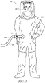
- the protective suit 100 may comprise a skin 102 and a breathable air receptacle 104.
- the breathable air receptacle 104 may comprise a flow control valve 107.
- a breathable air supply line 108 may be coupled to the breathable air receptacle 104 to provide breathable air and inflating pressure to the suit 100.
- the breathable air receptacle 104 may be referred to as a breathable air inlet.
- the suit 100 may be a single use suit that is disposed of after one use.
- the suit 100 may be desirable to dispose of the suit 100 after a single use rather than risk the suit contaminating clear areas, as may be the case if the exterior of the suit is exposed to hazardous materials such as radioactive particles. In manufacturing a single use suit 100, it may be desirable to reduce the cost of the suit 100 by using relatively inexpensive components in manufacturing the suit. In another embodiment, however, the suit 100 may be used a plurality of times.
- a user may don or put on the suit 100 and may further don or put on booties, shoes, or boots on the feet to protect the integrity of the feet of the suit 100 and gloves to seal the suit 100 at the hands.
- the suit 100 may be a fully encapsulated protective suit. Air for breathing under normal operating conditions may be provided by the breathable air supply line 108, for example an air hose coupled to a powered air purifying respirator device (not shown), and air within the suit 100 is breathed by the user. The air flow may provide additional functions, for example inflating the suit 100 and/or cooling the occupant of the suit 100.
- an exhaust valve (not shown) coupled to the suit 100 allows air to leave the suit.
- the suit 100 may be used in any contaminated environment, for example a workplace having radioactive materials and/or a nuclear powered electrical power generation facility.
- the suit 100 may be used as well in other contaminated environments. It is understood that in different embodiments the suit 100 may take different forms from that illustrated in FIG. 1 .
- a positive pressure differential be maintained between the interior and exterior of the suit 100.
- This positive pressure differential may provide a margin of safety. If a minor breach of the skin 102 occurs, contaminated material is not likely to enter the suit 100 but rather may be discouraged from entry by air flowing from the interior to the exterior of the suit 100 at the location of the minor breach. Additionally, the positive pressure differential promotes inflating the suit 100.
- a user wears a low pressure warning device 120, operable to sense the pressure within the suit 100.
- the low pressure warning device 120 may be suspended from the ear by a loop or wire that passes over the ear of a user.
- the low pressure warning device 120 may be carried by a head piece that passes over the top of the head of the user. In yet another example that is not part of the claimed invention, the low pressure warning device 120 may be suspended from the neck of the user or may clip to a shirt collar or a shirt closure worn by the user. It will be appreciated that according to examples that are not part of the claimed invention, the low pressure warning device 120 may be carried in other ways by the user.
- the low pressure warning device 120 indicates a low differential pressure operating condition of the suit 100
- the user of the suit may adjust the flow of the air supply from the line 108 by turning or otherwise adjusting the flow control valve 107. Generally it is desired that the suit 100 be relatively air-tight, with the possible exception of the exhaust valve described above, to promote efficiency.
- the protective hood 200 may comprise a skin 202 and a breathable air receptacle 204.
- the breathable air receptacle 104 may connect to a flow control valve 107.
- a breathable air supply line 208 may be coupled to the flow control valve 107, which may connect to an additional supply line 206 coupled to the breathable air receptacle 104 to provide breathable air and inflating pressure to the hood 200.
- the breathable air receptacle 204 may be referred to as a breathable air inlet.
- the hood 200 may be a single use hood that is disposed of after one use. It may be desirable to dispose of the hood 200 after a single use rather than risk the hood contaminating clear areas, as may be the case if the exterior of the hood is exposed to hazardous materials such as radioactive particles. In manufacturing a single use hood 200, it may be desirable to reduce the cost of the hood 200 by using relatively inexpensive components in manufacturing the suit. In another embodiment, however, the hood 200 may be used a plurality of times.
- the hood 200 may be worn with a protective suit 230.
- the user dons or puts on the hood 200 and suit 230 and may further don or put on booties, shoes, or boots on the feet to protect the integrity of the feet of the suit 230 and gloves to seal the suit 230 at the hands.
- the suit 230 may be a fully encapsulated protective suit and the hood 200 may be a fully encapsulated protective hood.
- Air for breathing under normal operating conditions may be provided by the breathable air supply line 208 and 206, for example an air hose coupled to a powered air purifying respirator device (not shown), and air within the hood 200 is breathed by the user.
- the air flow may provide additional functions, for example inflating the hood 200 and/or cooling the occupant of the hood 200 and suit 230.
- an exhaust valve (not shown) coupled to the hood 200 allows air to leave the suit.
- the hood 200 may be used in any contaminated environment, for example a workplace having radioactive materials and/or a nuclear powered electrical power generation facility.
- the hood 200 may be used as well in other contaminated environments. It is understood that in different embodiments the hood 200 may take different forms from that illustrated in FIG. 2 .
- a positive pressure differential be maintained between the interior and exterior of the hood 200.
- This positive pressure differential may provide a margin of safety. If a minor breach of the skin 202 occurs, contaminated material is not likely to enter the hood 200 but rather may be discouraged from entry by air flowing from the interior to the exterior of the hood 200 at the location of the minor breach. Additionally, the positive pressure differential promotes inflating the hood 200.
- a user wears a low pressure warning device 220, operable to sense the pressure within the hood 200.
- the user of the suit may adjust the flow of the air supply from the lines 208 and 206 by turning or otherwise adjusting the flow control valve 207.
- the hood 200 be relatively air-tight, with the possible exception of the exhaust valve described above, to promote efficiency.
- the low pressure warning device 220 may be substantially similar to the low pressure warning device 120 described above in FIG. 1 .
- a given pressure level or pressure differential may be preferred for a given suit 100 or hood 200 (as described above in FIGS. 1 and 2 ) and a given environment in which the suit 100 is to be used.
- a different pressure or pressure differential may be preferred for different suits 100 (or hoods 200) and/or different environments.
- a pressure of X PSI may be preferred while for a second suit 100 used in the first environment, a pressure of Y PSI may be preferred, where X does not equal Y.
- a pressure of X PSI may be preferred while for the first suit 100 used in a second environment, a pressure of Z PSI may be preferred, where X does not equal Z.
- a manufacturer of encapsulated protective suits 100 may need to stock a plurality of different low pressure warning devices that conform to the prior art (i.e., low pressure warning devices that are not adjustable after assembly) that are calibrated for indicating different low pressure warning thresholds for use in different suits 100 and/or for use in different environments. Maintaining adequate stock of each of the differently calibrated low pressure warning devices that conform to the prior art may entail significant inventory costs for the manufacturer of the suits 100 and/or hoods 200.
- the opportunity for assembling the suit 100 and/or hood 200 using the wrong prior art non-adjustable warning device may be considered a disadvantage.
- the present disclosure teaches a low pressure warning device 120 that has an adjustable indication threshold.
- the same low pressure warning device 120 (or 220) may be adjusted to indicate a low pressure or pressure differential condition at different thresholds.
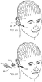
- FIGS. 3A-3C illustrate embodiments of a low pressure warning device that may be worn with a suit and/or hood as described above in FIGS. 1 and 2 .
- the low pressure warning device comprises the form of an earpiece 300, and may be operable to attach (or be retained) to a user's ear.
- the low pressure warning device may be carried or worn in another way by the user.
- the earpiece 300 may comprise a retaining piece 310, wherein the retaining piece 310 may be operable to retain and/or attach the earpiece 300 to the user's ear.
- the earpiece 300 may also comprise a casing 302 which may enclose a control system 330 and an alert system therein and may connect to the retaining piece 310.
- the alert system may comprise an audible alert 340 and a visual alert 320.
- FIG. 3B shows an embodiment of the earpiece 300 in a partially exploded view.
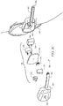
- the casing 302 may comprise an outer casing 304 and an inner casing 306, wherein the control system 330 may be located between the outer 304 and inner 306 casing.
- the control system 330 may comprise components operable to sense the pressure of the environment proximate to the earpiece 300 and activate the alert system (visual and/or audio) if the sensed pressure is lower than a predetermined (or predefined) minimum value.
- FIG. 3C shows an exploded view of an embodiment of the earpiece 300, wherein the control system 330 may comprise a pressure sensor 332, a battery 334 (optionally connected to a charging socket 335), a processor 336, a PCB (printed circuit board) 338, and an audio alert 340.
- the audio alert 340 may in some embodiments comprise a buzzer, a speaker, and/or a vibrator.
- the audio alert 340 may be controlled by the processor 336.
- the visual alert 320 may be controlled by the processor 336.
- the processor 336 may be one or more of a microcontroller, a microprocessor, a digital signal processor (DSP), a programmable logic device (PLD), a field programmable logic device (FPLD), an application specific integrated circuit (ASIC), or the like.
- the processor 336 may activate the visual alert 320 and/or the audio alert 340 if the pressure sensor 332 senses or detects a pressure lower than a predefined minimum value (wherein the minimum value may be communicated to the processor 336, for example).
- the inner case 306 may comprise an opening 308 operable to allow sound/vibration from the audio alert 340 to reach a user's ear.
- the inner case 306 may comprise an in-ear portion operable to fit within a user's ear, wherein the audio alert 340 may be communicated to the user via the in-ear portion.
- the PCB 338 may provide communication between the components of the earpiece 300, wherein the audio alert 340, battery 334, processor 336, and pressure sensor 332 may connect to the PCB 338.
- the outer case 304 may comprise a switch (or button) 350 operable to activate the pressure sensor 332 when pressed by a user.
- the switch 350 may signal the pressure sensor 332 to begin sensing the pressure of the environment proximate to the earpiece 300.
- the pressure sensor 332 may comprise an absolute pressure sensor (wherein the pressure sensor may be operable to sense absolute pressure).
- the processor 336 may control the interaction between the switch 350 and the pressure sensor 332.
- the pressure sensor 332 may be activated by the processor 336.
- the pressure sensor 332 may, in some embodiments, monitor/sense the pressure of the environment proximate to the earpiece 300 continuously and/or repeatedly, wherein the sensed pressure value may be continuously and/or repeatedly communicated to the processor 336.
- the processor 336 (and/or the pressure sensor 332) may compare the pressure sensed by the pressure sensor 332 with a predetermined (or predefined) minimum pressure value, wherein if the sensed pressure is lower than the predefined minimum value, the alert system (comprising the audio alert 340 and visual alert 320) may be activated.
- the audio alert 340 when the alert system is activated, the audio alert 340 may sound and/or vibrate (wherein a user may hear and/or feel the audio alert) and the visual alert 320 may produce a light (which may for example be a red light). In an embodiment, when the alert system is deactivated, the audio alert 340 may not sound, and the visual alert 320 may produce a light of a different color (which may for example be a green light). In an embodiment, the light may comprise a bi-color LED, and may in some embodiments comprise one or more flashing LEDs.
- the low pressure warning device may additionally comprise a wireless communication capability, which may for example be provided by a short range radio transceiver (which may communicate using Bluetooth, for example).
- the processor 336 may house the short range radio transceiver, while in other embodiments, the short range radio transceiver may be located on the PCB 338.
- the short range radio transceiver may be operable to communicate information between the earpiece 300 and an external computer system.
- the minimum pressure value may be communicated to the earpiece 300 from a control station as a part of a configuration or initialization process.
- the pressure sensor 332 may be activated and/or deactivated by the processor 336 as indicated by a communication via the wireless connection.
- the earpiece 300 may communicate pressure information gathered by the pressure sensor 332 to a monitoring station via the short range radio transceiver. For example, one or more logs of sensed pressure may be stored during use of the low pressure warning device (earpiece 300) and transmitted at the end of a work shift to the monitoring station. Logs of sensed pressure may also be transmitted to the monitoring station on an on-going basis. Additionally, low pressure alarming events may be logged and transmitted to the monitoring station.
- the pressure information and/or alarm information may be documented and could be used when compiling safety reports, for example, and may also be used when evaluating the safety of a particular environment and/or suit worn in the environment.
- the audio alert 340 may optionally be in communication with the short range radio transceiver, wherein the radio transceiver may be operable to wirelessly communicate audio (such as a prerecorded message and/or live communication) to the user via the audio alert 340.
- the short range radio transceiver may wirelessly communicate with a station within the hazardous environment where a suit or hood may be worn, wherein the station may then communicate with a base station (via a wired connection) wherein the base station may, for example, be located in a safe area outside of the hazardous environment.
- the earpiece 300 may comprise a charging socket 335 operable to receive a cord (or other means of charging) and allow for charging of the battery 334, wherein the battery 334 may be a rechargeable battery.
- the charging socket 335 may be accessible for a charging cord when the earpiece 300 is assembled, wherein for example, a portion of the charging socket 335 may extend from the earpiece 300 and/or the earpiece 300 may comprise an opening to allow access to the charging socket 335.
- a method 400 may comprise setting a minimum pressure limit P2 and communicating this limit to the low pressure warning device, at block 402. The method may then comprise sensing the pressure P1 of the environment proximate to the low pressure warning device (which may be accomplished by activating a pressure sensor at block 404). A step, shown at block 406, may then comprise comparing the sensed pressure P1 with the minimum pressure limit P2. If the sensed pressure P1 is lower (or not greater than) than the minimum pressure limit P2, a step may comprise activating an alert system, wherein the alert system may comprise a visual alert and/or an audio alert.
- a step may also include transmitting alert information via a short range radio transceiver to the monitoring station. If the sensed pressure P1 is higher (or greater) than the minimum pressure limit P2, the alert system may not be activated (or may be deactivated). In an embodiment, when the alert system is not activated, the audio alert may not sound and the visual alert may change color and/or not display.
- the alert system may be operable to convey multiple alerts to a user.
- the alert system may comprise a bi-color LED, wherein a first color indicates that the sensed pressure P1 is lower (or not greater than) than the minimum pressure limit P2 and a second color indicates that the sensed pressure P1 is higher (or greater) than the minimum pressure limit P2.
- a negative signal may be sent to the processor from the pressure sensor at block 408 if the sensed pressure P1 is not greater than the minimum pressure limit P2.
- the processor may then activate the alert system at block 410 such that the audio alert may be activated and the LED may show red.
- the pressure sensor may continue to sense/monitor the pressure (at block 412) and the steps of blocks 406, 408, 410, 414, and 416 may be repeated.
- a positive signal may be sent to the processor from the pressure sensor at block 414.
- the processor may then activate (or deactivate) the alert system at block 416 such that the audio alert may be deactivated and the LED may show green.
- the pressure sensor may continue to sense/monitor the pressure (at block 412) and the steps of blocks 406, 408, 410, 414, and 416 may be repeated.
- the method 400 may continue repeating as shown in FIG. 4 until the low pressure warning device is deactivated by a user, which may for example be achieved by pressing a switch on the device.
Landscapes
- Business, Economics & Management (AREA)
- Emergency Management (AREA)
- Health & Medical Sciences (AREA)
- Physics & Mathematics (AREA)
- General Physics & Mathematics (AREA)
- Engineering & Computer Science (AREA)
- Computer Networks & Wireless Communication (AREA)
- General Health & Medical Sciences (AREA)
- Pulmonology (AREA)
- Signal Processing (AREA)
- Toxicology (AREA)
- Alarm Systems (AREA)
- Respiratory Apparatuses And Protective Means (AREA)
- Emergency Alarm Devices (AREA)
- Telephone Set Structure (AREA)
- Headphones And Earphones (AREA)
- Helmets And Other Head Coverings (AREA)
Claims (15)
- Écouteur (300) adapté pour être portée avec une combinaison de protection encapsulée (100) ou une cagoule (200) comprenant :un boîtier (302) ;une batterie (334) située dans le boîtier ;un capteur de pression (332) situé à l'intérieur du boîtier, permettant de détecter la pression de l'environnement à proximité de l'écouteur (300) et alimenté par la batterie ;un système d'alerte situé à l'intérieur du boîtier et alimenté par la batterie ; etun processeur (336) en communication avec le capteur de pression et le système d'alerte, dans lequel le processeur peut fonctionner pour déclencher le système d'alerte lorsque le capteur de pression indique une pression inférieure à une valeur minimale prédéterminée, dans lequel la valeur minimale prédéterminée est choisie supérieure à la pression de l'environnement à l'extérieur de la combinaison ou de la cagoule de protection encapsulée.
- Écouteur (300) selon la revendication 1, dans lequel le boîtier (302) comprend un boîtier extérieur (304), un boîtier intérieur (306) et une pièce de retenue (310), dans lequel la pièce de retenue fixe l'écouteur à l'oreille d'un utilisateur.
- Écouteur (300) selon la revendication 1, dans lequel le système d'alerte comprend une alerte sonore (340) et une alerte visuelle (320).
- Écouteur (300) selon la revendication 3, dans lequel l'alerte sonore (340) comprend au moins l'un parmi : un haut-parleur, un buzzer ou un vibreur.
- Écouteur (300) selon la revendication 3, dans lequel l'alerte visuelle (320) comprend une LED bicolore dans laquelle une couleur indique une pression inférieure à la valeur minimale prédéterminée et l'autre couleur indique une pression supérieure à la valeur minimale prédéterminée.
- Écouteur (300) selon la revendication 1, comprenant en outre un interrupteur (350) qui peut être actionné pour signaler au capteur de pression (332) de commencer à détecter la pression.
- Écouteur (300) selon la revendication 1, dans lequel le processeur (336) peut fonctionner pour communiquer avec une station de surveillance via une connexion sans fil.
- Écouteur (300) selon la revendication 7, dans lequel le système d'alerte comprend une alerte sonore (340), et dans lequel l'alerte sonore comprend au moins l'un parmi : un haut-parleur, un buzzer ou un vibreur.
- Écouteur (300) selon la revendication 7, dans lequel le système d'alerte comprend une alerte visuelle (320), et dans lequel l'alerte visuelle comprend une LED bicolore dans laquelle une couleur indique une pression inférieure à la valeur minimale prédéterminée et l'autre couleur indique une pression supérieure à la valeur minimale prédéterminée.
- Écouteur (300) selon la revendication 7, dans lequel le capteur de pression (332) est un capteur de pression absolue.
- Écouteur (300) selon la revendication 7, comprenant en outre une batterie (334) pouvant fonctionner pour alimenter les composants du dispositif, et comprenant en outre une prise de charge (335) connectée à la batterie et pouvant fonctionner pour permettre la charge de la batterie, dans lequel la batterie est une batterie rechargeable.
- Écouteur (300) selon la revendication 7, dans lequel le processeur est en outre configuré pour recevoir la valeur de pression minimale prédéterminée via la connexion sans fil.
- Procédé d'utilisation d'un écouteur (300) selon l'une quelconque des revendications 1 à 12 porté avec une combinaison de protection encapsulée (100) ou une cagoule (200) comprenant :le réglage (402) de la valeur minimale prédéterminée de l'écouteur (300) comme une limite de pression minimale, dans lequel la limite de pression minimale est choisie pour être supérieure à la pression de l'environnement à l'extérieur de la combinaison ou de la cagoule de protection encapsulée ;l'activation (404) du capteur de pression (332) de l'écouteur (300) ;la détection (412) de la pression de l'environnement à l'intérieur de la combinaison de protection ou de la cagoule encapsulée par l'écouteur (300) ;la comparaison (406) de la pression détectée par l'écouteur (300) avec la limite de pression minimale ; etl'activation (410) du système d'alerte si la pression détectée par l'écouteur (300) est inférieure à la limite de pression minimale.
- Procédé selon la revendication 13, dans lequel l'étape de détection (412) de la pression de l'environnement à proximité de l'écouteur (300) est répétée de manière continue.
- Procédé selon la revendication 13, dans lequel, si la pression détectée est supérieure à la limite de pression minimale, le système d'alerte est désactivé (416).
Applications Claiming Priority (1)
| Application Number | Priority Date | Filing Date | Title |
|---|---|---|---|
| US13/732,568 US9000913B2 (en) | 2013-01-02 | 2013-01-02 | Wearable low pressure warning device with audio and visual indication |
Publications (3)
| Publication Number | Publication Date |
|---|---|
| EP2752829A2 EP2752829A2 (fr) | 2014-07-09 |
| EP2752829A3 EP2752829A3 (fr) | 2017-01-25 |
| EP2752829B1 true EP2752829B1 (fr) | 2021-04-21 |
Family
ID=49765306
Family Applications (1)
| Application Number | Title | Priority Date | Filing Date |
|---|---|---|---|
| EP13195564.3A Active EP2752829B1 (fr) | 2013-01-02 | 2013-12-03 | Dispositif d'avertissement basse pression portable avec indication visuelle et audio |
Country Status (3)
| Country | Link |
|---|---|
| US (1) | US9000913B2 (fr) |
| EP (1) | EP2752829B1 (fr) |
| CN (1) | CN103913268B (fr) |
Families Citing this family (13)
| Publication number | Priority date | Publication date | Assignee | Title |
|---|---|---|---|---|
| US11027156B2 (en) | 2011-10-21 | 2021-06-08 | Honeywell International Inc. | Emergency filter system for ventilated hood |
| US10004925B2 (en) | 2011-10-21 | 2018-06-26 | Honeywell International Inc. | Emergency filter system for encapsulated suit |
| ES2573852T3 (es) * | 2014-04-07 | 2016-06-10 | Honeywell International Inc. | Sistema de distribución de aire integral en la parte posterior en un traje ventilado |
| US10064758B2 (en) * | 2015-10-20 | 2018-09-04 | Cirrus Healthcare Products, Llc | Method, apparatus and computer program for provision of meterological data to assist in timing of remedy to ameliorate physical distress |
| US10307622B2 (en) | 2016-04-14 | 2019-06-04 | Special Projects Operations, Inc. | High-pressure passthrough for protective suit |
| JP6984281B2 (ja) * | 2017-09-27 | 2021-12-17 | トヨタ自動車株式会社 | 車両状態提示システム、車両、端末装置、および、方法 |
| CN111387618A (zh) * | 2020-03-24 | 2020-07-10 | 孟晓丽 | 全封闭医用防护服的生命支持系统 |
| USD912331S1 (en) * | 2020-04-20 | 2021-03-02 | Marty Gilman, Inc. | Isolation hood |
| USD945707S1 (en) | 2020-04-20 | 2022-03-08 | Marty Gilman, Inc. | Isolation hood |
| CN111617396B (zh) * | 2020-05-07 | 2022-02-25 | 深圳迪致科技术有限公司 | 正压呼吸器 |
| US11612770B1 (en) * | 2020-11-09 | 2023-03-28 | Golden Galaxy Corporation | PPE with rotating assembly providing multiple face covers |
| US11364396B2 (en) * | 2020-11-09 | 2022-06-21 | Golden Galaxy Corporation | PPE with rotating assembly providing multiple face covers |
| EP4648641A1 (fr) * | 2023-01-09 | 2025-11-19 | Amulet Critical Infrastructure, Inc. | Gilet de sécurité balistique à haute visibilité |
Citations (1)
| Publication number | Priority date | Publication date | Assignee | Title |
|---|---|---|---|---|
| US20060213517A1 (en) * | 2005-03-22 | 2006-09-28 | Mashak James N | Arrangement and method for controlling operational characteristics of medical equipment |
Family Cites Families (24)
| Publication number | Priority date | Publication date | Assignee | Title |
|---|---|---|---|---|
| AU4230472A (en) | 1971-03-12 | 1973-11-22 | Save-A-Tyre Limited | Improvements in or relating to air pressure operated warning devices |
| US3934223A (en) | 1973-12-04 | 1976-01-20 | Safety Research & Engineering Corporation | Tire pressure warning system |
| US4100537A (en) | 1977-08-08 | 1978-07-11 | Taylor Medical Oxygen Services, Inc. | Monitor for gas piping system |
| US4174673A (en) | 1978-04-06 | 1979-11-20 | Steven Kwan | Low pressure warning tire air valve cap |
| US4286253A (en) | 1979-08-24 | 1981-08-25 | Nagy Emery J | Tire pressure sensing and alarm system |
| US4707953A (en) | 1983-03-30 | 1987-11-24 | Brunswick Corporation | Expandable shelter system providing collective protection |
| US4800373A (en) | 1987-08-25 | 1989-01-24 | Allan Mayz | Low pressure warning device for scuba divers |
| GB8829565D0 (en) * | 1988-12-19 | 1989-02-08 | Bilsom Sentry Ltd | Improvements in or relating to warning apparatus |
| US5157378A (en) | 1991-08-06 | 1992-10-20 | North-South Corporation | Integrated firefighter safety monitoring and alarm system |
| CN2144839Y (zh) * | 1992-08-31 | 1993-10-27 | 冯文渊 | 有害气体安全报警帽 |
| SE9203931L (sv) | 1992-12-29 | 1994-06-30 | Interspiro Ab | Optisk varningsanordning |
| US5652966A (en) * | 1994-07-11 | 1997-08-05 | Reinert, Sr.; Gary L. | Reinforced full body suit |
| US20020139370A1 (en) * | 2001-03-29 | 2002-10-03 | Bachinski Thomas J. | Sensor for pilot mask |
| US20030112136A1 (en) | 2001-12-14 | 2003-06-19 | Reidhead Rodney B. | Tire pressure warning device |
| US7000483B2 (en) | 2003-02-03 | 2006-02-21 | Dielectrics Industries, Inc. | Inflatable manometers |
| FR2869237B1 (fr) | 2004-04-27 | 2006-12-29 | Delta Prot | Scaphandre ventile securise notamment pour milieu hostile |
| US7690379B2 (en) | 2004-06-01 | 2010-04-06 | Branch, Banking and Trust Company | Pressure indicator for positive pressure protection masks |
| US7342502B2 (en) * | 2005-06-16 | 2008-03-11 | Consort, Llc | Wireless short range communication system |
| US20100218305A1 (en) * | 2005-07-26 | 2010-09-02 | Richard Scott Weston | Negative pressure protection system |
| US20070283952A1 (en) * | 2006-06-13 | 2007-12-13 | Mark Wilbur | Pressure sensing in masks |
| US20110114093A1 (en) * | 2009-11-16 | 2011-05-19 | Honeywell International Inc. | Automatic fitment detection and flow calibration using non-contact sensing in powered air purifying respirators |
| US9792808B2 (en) * | 2009-11-19 | 2017-10-17 | Honeywell International Inc. | Alert system with zoning using wireless portable detectors and a central station |
| US20140190483A1 (en) | 2010-05-12 | 2014-07-10 | Critical Systems Innovations, Inc. | Self-Contained Integrated Emergency Life-Support Device And System |
| US20120150755A1 (en) * | 2010-12-10 | 2012-06-14 | Honeywell International Inc. | System and Method of Providing Compliance and Alerting of Toxic Gas Exposure for Health Monitoring and Plant Maintenance |
-
2013
- 2013-01-02 US US13/732,568 patent/US9000913B2/en active Active
- 2013-12-03 EP EP13195564.3A patent/EP2752829B1/fr active Active
- 2013-12-31 CN CN201310747281.2A patent/CN103913268B/zh active Active
Patent Citations (1)
| Publication number | Priority date | Publication date | Assignee | Title |
|---|---|---|---|---|
| US20060213517A1 (en) * | 2005-03-22 | 2006-09-28 | Mashak James N | Arrangement and method for controlling operational characteristics of medical equipment |
Also Published As
| Publication number | Publication date |
|---|---|
| US20140184407A1 (en) | 2014-07-03 |
| CN103913268A (zh) | 2014-07-09 |
| EP2752829A2 (fr) | 2014-07-09 |
| EP2752829A3 (fr) | 2017-01-25 |
| CN103913268B (zh) | 2018-12-11 |
| US9000913B2 (en) | 2015-04-07 |
Similar Documents
| Publication | Publication Date | Title |
|---|---|---|
| EP2752829B1 (fr) | Dispositif d'avertissement basse pression portable avec indication visuelle et audio | |
| CN109414603B (zh) | 用于防护头戴装置的改进型传感器模块 | |
| AU2017281368B9 (en) | Indicating hazardous exposure in a supplied air respirator system | |
| JP6316257B2 (ja) | 電動空気浄化式呼吸用保護具 | |
| US10877010B2 (en) | Clydesdale gas detector with improved screen orientation based on input from attachment sensor | |
| EP2653194B1 (fr) | Dispositif d'avertissement basse pression réglable | |
| WO2018215220A1 (fr) | Dispositif portatif pour commander des polluants gazeux | |
| KR20070084418A (ko) | 보호 장치 | |
| KR101305211B1 (ko) | 질식 방지용 스마트 마스크 및 그 제어방법 | |
| US20210264762A1 (en) | Improved Arboriculture Safety System | |
| US20230233886A1 (en) | Respirator | |
| US11857339B2 (en) | Headgear-type device for hazardous air quality warning and air quality improvement | |
| JP2004030180A (ja) | 防護装具のヒートストレス報知システム | |
| KR101791165B1 (ko) | 소방관용 경보장치 | |
| KR102080261B1 (ko) | 유해가스 검출 방독면 | |
| KR101674474B1 (ko) | 내열성 및 방수성이 확보된 손목착용식 경보장치 | |
| IT202000009337A1 (it) | Dispositivo di ventilazione per mascherine filtranti e relativo metodo di controllo e sistema di ventilazione comprendente tale dispositivo |
Legal Events
| Date | Code | Title | Description |
|---|---|---|---|
| 17P | Request for examination filed |
Effective date: 20131203 |
|
| AK | Designated contracting states |
Kind code of ref document: A2 Designated state(s): AL AT BE BG CH CY CZ DE DK EE ES FI FR GB GR HR HU IE IS IT LI LT LU LV MC MK MT NL NO PL PT RO RS SE SI SK SM TR |
|
| AX | Request for extension of the european patent |
Extension state: BA ME |
|
| PUAI | Public reference made under article 153(3) epc to a published international application that has entered the european phase |
Free format text: ORIGINAL CODE: 0009012 |
|
| RAP1 | Party data changed (applicant data changed or rights of an application transferred) |
Owner name: HONEYWELL INTERNATIONAL INC. |
|
| PUAL | Search report despatched |
Free format text: ORIGINAL CODE: 0009013 |
|
| AK | Designated contracting states |
Kind code of ref document: A3 Designated state(s): AL AT BE BG CH CY CZ DE DK EE ES FI FR GB GR HR HU IE IS IT LI LT LU LV MC MK MT NL NO PL PT RO RS SE SI SK SM TR |
|
| AX | Request for extension of the european patent |
Extension state: BA ME |
|
| RIC1 | Information provided on ipc code assigned before grant |
Ipc: G08B 25/10 20060101ALI20161222BHEP Ipc: G08B 21/02 20060101ALI20161222BHEP Ipc: A62B 17/00 20060101ALI20161222BHEP Ipc: A42B 3/30 20060101ALI20161222BHEP Ipc: B64D 10/00 20060101ALI20161222BHEP Ipc: A62B 9/00 20060101ALI20161222BHEP Ipc: A42B 3/04 20060101ALI20161222BHEP Ipc: A41D 13/002 20060101ALI20161222BHEP Ipc: G08B 21/18 20060101AFI20161222BHEP |
|
| STAA | Information on the status of an ep patent application or granted ep patent |
Free format text: STATUS: EXAMINATION IS IN PROGRESS |
|
| 17Q | First examination report despatched |
Effective date: 20170130 |
|
| GRAP | Despatch of communication of intention to grant a patent |
Free format text: ORIGINAL CODE: EPIDOSNIGR1 |
|
| STAA | Information on the status of an ep patent application or granted ep patent |
Free format text: STATUS: GRANT OF PATENT IS INTENDED |
|
| RIC1 | Information provided on ipc code assigned before grant |
Ipc: A42B 3/30 20060101ALI20201012BHEP Ipc: G08B 21/18 20060101AFI20201012BHEP Ipc: A62B 9/00 20060101ALI20201012BHEP Ipc: G08B 21/02 20060101ALI20201012BHEP Ipc: H04B 1/3827 20150101ALI20201012BHEP Ipc: B64D 10/00 20060101ALI20201012BHEP Ipc: G08B 25/10 20060101ALI20201012BHEP Ipc: A62B 17/00 20060101ALI20201012BHEP Ipc: A41D 13/002 20060101ALI20201012BHEP Ipc: A42B 3/04 20060101ALI20201012BHEP |
|
| INTG | Intention to grant announced |
Effective date: 20201112 |
|
| GRAS | Grant fee paid |
Free format text: ORIGINAL CODE: EPIDOSNIGR3 |
|
| GRAA | (expected) grant |
Free format text: ORIGINAL CODE: 0009210 |
|
| STAA | Information on the status of an ep patent application or granted ep patent |
Free format text: STATUS: THE PATENT HAS BEEN GRANTED |
|
| AK | Designated contracting states |
Kind code of ref document: B1 Designated state(s): AL AT BE BG CH CY CZ DE DK EE ES FI FR GB GR HR HU IE IS IT LI LT LU LV MC MK MT NL NO PL PT RO RS SE SI SK SM TR |
|
| REG | Reference to a national code |
Ref country code: GB Ref legal event code: FG4D |
|
| REG | Reference to a national code |
Ref country code: CH Ref legal event code: EP |
|
| REG | Reference to a national code |
Ref country code: DE Ref legal event code: R096 Ref document number: 602013076992 Country of ref document: DE Ref country code: IE Ref legal event code: FG4D |
|
| REG | Reference to a national code |
Ref country code: AT Ref legal event code: REF Ref document number: 1385462 Country of ref document: AT Kind code of ref document: T Effective date: 20210515 |
|
| REG | Reference to a national code |
Ref country code: LT Ref legal event code: MG9D |
|
| REG | Reference to a national code |
Ref country code: AT Ref legal event code: MK05 Ref document number: 1385462 Country of ref document: AT Kind code of ref document: T Effective date: 20210421 |
|
| REG | Reference to a national code |
Ref country code: NL Ref legal event code: MP Effective date: 20210421 |
|
| PG25 | Lapsed in a contracting state [announced via postgrant information from national office to epo] |
Ref country code: FI Free format text: LAPSE BECAUSE OF FAILURE TO SUBMIT A TRANSLATION OF THE DESCRIPTION OR TO PAY THE FEE WITHIN THE PRESCRIBED TIME-LIMIT Effective date: 20210421 Ref country code: LT Free format text: LAPSE BECAUSE OF FAILURE TO SUBMIT A TRANSLATION OF THE DESCRIPTION OR TO PAY THE FEE WITHIN THE PRESCRIBED TIME-LIMIT Effective date: 20210421 Ref country code: NL Free format text: LAPSE BECAUSE OF FAILURE TO SUBMIT A TRANSLATION OF THE DESCRIPTION OR TO PAY THE FEE WITHIN THE PRESCRIBED TIME-LIMIT Effective date: 20210421 Ref country code: BG Free format text: LAPSE BECAUSE OF FAILURE TO SUBMIT A TRANSLATION OF THE DESCRIPTION OR TO PAY THE FEE WITHIN THE PRESCRIBED TIME-LIMIT Effective date: 20210721 Ref country code: AT Free format text: LAPSE BECAUSE OF FAILURE TO SUBMIT A TRANSLATION OF THE DESCRIPTION OR TO PAY THE FEE WITHIN THE PRESCRIBED TIME-LIMIT Effective date: 20210421 Ref country code: HR Free format text: LAPSE BECAUSE OF FAILURE TO SUBMIT A TRANSLATION OF THE DESCRIPTION OR TO PAY THE FEE WITHIN THE PRESCRIBED TIME-LIMIT Effective date: 20210421 |
|
| PG25 | Lapsed in a contracting state [announced via postgrant information from national office to epo] |
Ref country code: PT Free format text: LAPSE BECAUSE OF FAILURE TO SUBMIT A TRANSLATION OF THE DESCRIPTION OR TO PAY THE FEE WITHIN THE PRESCRIBED TIME-LIMIT Effective date: 20210823 Ref country code: PL Free format text: LAPSE BECAUSE OF FAILURE TO SUBMIT A TRANSLATION OF THE DESCRIPTION OR TO PAY THE FEE WITHIN THE PRESCRIBED TIME-LIMIT Effective date: 20210421 Ref country code: NO Free format text: LAPSE BECAUSE OF FAILURE TO SUBMIT A TRANSLATION OF THE DESCRIPTION OR TO PAY THE FEE WITHIN THE PRESCRIBED TIME-LIMIT Effective date: 20210721 Ref country code: ES Free format text: LAPSE BECAUSE OF FAILURE TO SUBMIT A TRANSLATION OF THE DESCRIPTION OR TO PAY THE FEE WITHIN THE PRESCRIBED TIME-LIMIT Effective date: 20210421 Ref country code: RS Free format text: LAPSE BECAUSE OF FAILURE TO SUBMIT A TRANSLATION OF THE DESCRIPTION OR TO PAY THE FEE WITHIN THE PRESCRIBED TIME-LIMIT Effective date: 20210421 Ref country code: SE Free format text: LAPSE BECAUSE OF FAILURE TO SUBMIT A TRANSLATION OF THE DESCRIPTION OR TO PAY THE FEE WITHIN THE PRESCRIBED TIME-LIMIT Effective date: 20210421 Ref country code: GR Free format text: LAPSE BECAUSE OF FAILURE TO SUBMIT A TRANSLATION OF THE DESCRIPTION OR TO PAY THE FEE WITHIN THE PRESCRIBED TIME-LIMIT Effective date: 20210722 Ref country code: LV Free format text: LAPSE BECAUSE OF FAILURE TO SUBMIT A TRANSLATION OF THE DESCRIPTION OR TO PAY THE FEE WITHIN THE PRESCRIBED TIME-LIMIT Effective date: 20210421 Ref country code: IS Free format text: LAPSE BECAUSE OF FAILURE TO SUBMIT A TRANSLATION OF THE DESCRIPTION OR TO PAY THE FEE WITHIN THE PRESCRIBED TIME-LIMIT Effective date: 20210821 |
|
| REG | Reference to a national code |
Ref country code: DE Ref legal event code: R097 Ref document number: 602013076992 Country of ref document: DE |
|
| PG25 | Lapsed in a contracting state [announced via postgrant information from national office to epo] |
Ref country code: RO Free format text: LAPSE BECAUSE OF FAILURE TO SUBMIT A TRANSLATION OF THE DESCRIPTION OR TO PAY THE FEE WITHIN THE PRESCRIBED TIME-LIMIT Effective date: 20210421 Ref country code: DK Free format text: LAPSE BECAUSE OF FAILURE TO SUBMIT A TRANSLATION OF THE DESCRIPTION OR TO PAY THE FEE WITHIN THE PRESCRIBED TIME-LIMIT Effective date: 20210421 Ref country code: EE Free format text: LAPSE BECAUSE OF FAILURE TO SUBMIT A TRANSLATION OF THE DESCRIPTION OR TO PAY THE FEE WITHIN THE PRESCRIBED TIME-LIMIT Effective date: 20210421 Ref country code: CZ Free format text: LAPSE BECAUSE OF FAILURE TO SUBMIT A TRANSLATION OF THE DESCRIPTION OR TO PAY THE FEE WITHIN THE PRESCRIBED TIME-LIMIT Effective date: 20210421 Ref country code: SK Free format text: LAPSE BECAUSE OF FAILURE TO SUBMIT A TRANSLATION OF THE DESCRIPTION OR TO PAY THE FEE WITHIN THE PRESCRIBED TIME-LIMIT Effective date: 20210421 Ref country code: SM Free format text: LAPSE BECAUSE OF FAILURE TO SUBMIT A TRANSLATION OF THE DESCRIPTION OR TO PAY THE FEE WITHIN THE PRESCRIBED TIME-LIMIT Effective date: 20210421 |
|
| PLBE | No opposition filed within time limit |
Free format text: ORIGINAL CODE: 0009261 |
|
| STAA | Information on the status of an ep patent application or granted ep patent |
Free format text: STATUS: NO OPPOSITION FILED WITHIN TIME LIMIT |
|
| 26N | No opposition filed |
Effective date: 20220124 |
|
| PG25 | Lapsed in a contracting state [announced via postgrant information from national office to epo] |
Ref country code: IS Free format text: LAPSE BECAUSE OF FAILURE TO SUBMIT A TRANSLATION OF THE DESCRIPTION OR TO PAY THE FEE WITHIN THE PRESCRIBED TIME-LIMIT Effective date: 20210821 Ref country code: AL Free format text: LAPSE BECAUSE OF FAILURE TO SUBMIT A TRANSLATION OF THE DESCRIPTION OR TO PAY THE FEE WITHIN THE PRESCRIBED TIME-LIMIT Effective date: 20210421 |
|
| PG25 | Lapsed in a contracting state [announced via postgrant information from national office to epo] |
Ref country code: MC Free format text: LAPSE BECAUSE OF FAILURE TO SUBMIT A TRANSLATION OF THE DESCRIPTION OR TO PAY THE FEE WITHIN THE PRESCRIBED TIME-LIMIT Effective date: 20210421 Ref country code: IT Free format text: LAPSE BECAUSE OF FAILURE TO SUBMIT A TRANSLATION OF THE DESCRIPTION OR TO PAY THE FEE WITHIN THE PRESCRIBED TIME-LIMIT Effective date: 20210421 |
|
| REG | Reference to a national code |
Ref country code: CH Ref legal event code: PL |
|
| REG | Reference to a national code |
Ref country code: BE Ref legal event code: MM Effective date: 20211231 |
|
| PG25 | Lapsed in a contracting state [announced via postgrant information from national office to epo] |
Ref country code: LU Free format text: LAPSE BECAUSE OF NON-PAYMENT OF DUE FEES Effective date: 20211203 Ref country code: IE Free format text: LAPSE BECAUSE OF NON-PAYMENT OF DUE FEES Effective date: 20211203 |
|
| PG25 | Lapsed in a contracting state [announced via postgrant information from national office to epo] |
Ref country code: BE Free format text: LAPSE BECAUSE OF NON-PAYMENT OF DUE FEES Effective date: 20211231 |
|
| PG25 | Lapsed in a contracting state [announced via postgrant information from national office to epo] |
Ref country code: LI Free format text: LAPSE BECAUSE OF NON-PAYMENT OF DUE FEES Effective date: 20211231 Ref country code: CH Free format text: LAPSE BECAUSE OF NON-PAYMENT OF DUE FEES Effective date: 20211231 |
|
| PG25 | Lapsed in a contracting state [announced via postgrant information from national office to epo] |
Ref country code: HU Free format text: LAPSE BECAUSE OF FAILURE TO SUBMIT A TRANSLATION OF THE DESCRIPTION OR TO PAY THE FEE WITHIN THE PRESCRIBED TIME-LIMIT; INVALID AB INITIO Effective date: 20131203 |
|
| PG25 | Lapsed in a contracting state [announced via postgrant information from national office to epo] |
Ref country code: CY Free format text: LAPSE BECAUSE OF FAILURE TO SUBMIT A TRANSLATION OF THE DESCRIPTION OR TO PAY THE FEE WITHIN THE PRESCRIBED TIME-LIMIT Effective date: 20210421 |
|
| PG25 | Lapsed in a contracting state [announced via postgrant information from national office to epo] |
Ref country code: MK Free format text: LAPSE BECAUSE OF FAILURE TO SUBMIT A TRANSLATION OF THE DESCRIPTION OR TO PAY THE FEE WITHIN THE PRESCRIBED TIME-LIMIT Effective date: 20210421 |
|
| PG25 | Lapsed in a contracting state [announced via postgrant information from national office to epo] |
Ref country code: MT Free format text: LAPSE BECAUSE OF FAILURE TO SUBMIT A TRANSLATION OF THE DESCRIPTION OR TO PAY THE FEE WITHIN THE PRESCRIBED TIME-LIMIT Effective date: 20210421 |
|
| REG | Reference to a national code |
Ref country code: DE Ref legal event code: R081 Ref document number: 602013076992 Country of ref document: DE Owner name: HONEYWELL SAFETY PRODUCTS USA, INC., WILMINGTO, US Free format text: FORMER OWNER: HONEYWELL INTERNATIONAL INC., MORRIS PLAINS, N.J., US |
|
| REG | Reference to a national code |
Ref country code: GB Ref legal event code: 732E Free format text: REGISTERED BETWEEN 20250515 AND 20250521 |
|
| PG25 | Lapsed in a contracting state [announced via postgrant information from national office to epo] |
Ref country code: TR Free format text: LAPSE BECAUSE OF FAILURE TO SUBMIT A TRANSLATION OF THE DESCRIPTION OR TO PAY THE FEE WITHIN THE PRESCRIBED TIME-LIMIT Effective date: 20210421 |
|
| PGFP | Annual fee paid to national office [announced via postgrant information from national office to epo] |
Ref country code: GB Payment date: 20251223 Year of fee payment: 13 |
|
| PGFP | Annual fee paid to national office [announced via postgrant information from national office to epo] |
Ref country code: FR Payment date: 20251223 Year of fee payment: 13 |
|
| PGFP | Annual fee paid to national office [announced via postgrant information from national office to epo] |
Ref country code: DE Payment date: 20251229 Year of fee payment: 13 |