EP2752650A1 - Force sensor and robot - Google Patents
Force sensor and robot Download PDFInfo
- Publication number
- EP2752650A1 EP2752650A1 EP11871463.3A EP11871463A EP2752650A1 EP 2752650 A1 EP2752650 A1 EP 2752650A1 EP 11871463 A EP11871463 A EP 11871463A EP 2752650 A1 EP2752650 A1 EP 2752650A1
- Authority
- EP
- European Patent Office
- Prior art keywords
- base member
- sensor elements
- load sensor
- load
- force sensor
- Prior art date
- Legal status (The legal status is an assumption and is not a legal conclusion. Google has not performed a legal analysis and makes no representation as to the accuracy of the status listed.)
- Withdrawn
Links
Images




Classifications
-
- G—PHYSICS
- G01—MEASURING; TESTING
- G01L—MEASURING FORCE, STRESS, TORQUE, WORK, MECHANICAL POWER, MECHANICAL EFFICIENCY, OR FLUID PRESSURE
- G01L5/00—Apparatus for, or methods of, measuring force, work, mechanical power, or torque, specially adapted for specific purposes
- G01L5/0028—Force sensors associated with force applying means
-
- B—PERFORMING OPERATIONS; TRANSPORTING
- B25—HAND TOOLS; PORTABLE POWER-DRIVEN TOOLS; MANIPULATORS
- B25J—MANIPULATORS; CHAMBERS PROVIDED WITH MANIPULATION DEVICES
- B25J13/00—Controls for manipulators
- B25J13/08—Controls for manipulators by means of sensing devices, e.g. viewing or touching devices
- B25J13/085—Force or torque sensors
-
- B—PERFORMING OPERATIONS; TRANSPORTING
- B25—HAND TOOLS; PORTABLE POWER-DRIVEN TOOLS; MANIPULATORS
- B25J—MANIPULATORS; CHAMBERS PROVIDED WITH MANIPULATION DEVICES
- B25J9/00—Program-controlled manipulators
- B25J9/16—Program controls
- B25J9/1628—Program controls characterised by the control loop
- B25J9/1633—Program controls characterised by the control loop compliant, force, torque control, e.g. combined with position control
-
- G—PHYSICS
- G01—MEASURING; TESTING
- G01L—MEASURING FORCE, STRESS, TORQUE, WORK, MECHANICAL POWER, MECHANICAL EFFICIENCY, OR FLUID PRESSURE
- G01L5/00—Apparatus for, or methods of, measuring force, work, mechanical power, or torque, specially adapted for specific purposes
- G01L5/16—Apparatus for, or methods of, measuring force, work, mechanical power, or torque, specially adapted for specific purposes for measuring several components of force
- G01L5/161—Apparatus for, or methods of, measuring force, work, mechanical power, or torque, specially adapted for specific purposes for measuring several components of force using variations in ohmic resistance
- G01L5/162—Apparatus for, or methods of, measuring force, work, mechanical power, or torque, specially adapted for specific purposes for measuring several components of force using variations in ohmic resistance of piezoresistors
-
- G—PHYSICS
- G05—CONTROLLING; REGULATING
- G05B—CONTROL OR REGULATING SYSTEMS IN GENERAL; FUNCTIONAL ELEMENTS OF SUCH SYSTEMS; MONITORING OR TESTING ARRANGEMENTS FOR SUCH SYSTEMS OR ELEMENTS
- G05B2219/00—Program-control systems
- G05B2219/30—Nc systems
- G05B2219/40—Robotics, robotics mapping to robotics vision
- G05B2219/40586—6-DOF force sensor
-
- Y—GENERAL TAGGING OF NEW TECHNOLOGICAL DEVELOPMENTS; GENERAL TAGGING OF CROSS-SECTIONAL TECHNOLOGIES SPANNING OVER SEVERAL SECTIONS OF THE IPC; TECHNICAL SUBJECTS COVERED BY FORMER USPC CROSS-REFERENCE ART COLLECTIONS [XRACs] AND DIGESTS
- Y10—TECHNICAL SUBJECTS COVERED BY FORMER USPC
- Y10S—TECHNICAL SUBJECTS COVERED BY FORMER USPC CROSS-REFERENCE ART COLLECTIONS [XRACs] AND DIGESTS
- Y10S901/00—Robots
- Y10S901/02—Arm motion controller
- Y10S901/09—Closed loop, sensor feedback controls arm movement
-
- Y—GENERAL TAGGING OF NEW TECHNOLOGICAL DEVELOPMENTS; GENERAL TAGGING OF CROSS-SECTIONAL TECHNOLOGIES SPANNING OVER SEVERAL SECTIONS OF THE IPC; TECHNICAL SUBJECTS COVERED BY FORMER USPC CROSS-REFERENCE ART COLLECTIONS [XRACs] AND DIGESTS
- Y10—TECHNICAL SUBJECTS COVERED BY FORMER USPC
- Y10T—TECHNICAL SUBJECTS COVERED BY FORMER US CLASSIFICATION
- Y10T74/00—Machine element or mechanism
- Y10T74/20—Control lever and linkage systems
- Y10T74/20207—Multiple controlling elements for single controlled element
- Y10T74/20305—Robotic arm
Definitions
- the present invention relates to a force sensor and a robot.
- Patent Literature 1 describes a multiaxial force sensor capable of detecting at least the following elements: three components of force acting in the X-axis, Y-axis, and Z-axis coordinate directions perpendicular to each other and moments around the X-axis and Y-axis.
- This multiaxial force sensor includes an outer ring part having a ring-shaped inner peripheral surface centered on the coordinate origin O on a reference plane including the X-axis and Y-axis, an inner ring part having a ring-shaped outer peripheral surface facing the inner peripheral surface of the outer ring part, and a plurality of load sensor elements connecting the inner peripheral surface and the outer peripheral surface.
- the inner peripheral surface of the outer ring part has a tapered inner surface that is inclined with respect to the Z-axis.
- the outer peripheral surface of the inner ring part has a tapered outer surface that is inclined with respect to the Z-axis such that it faces the tapered inner surface.
- the load sensor elements are interposed between the tapered inner surface and the tapered outer surface.
- Patent Literature 1 Japanese Patent Application Laid-open No. 2006-071506
- the load sensor elements may be broken.
- the present invention aims to provide a force sensor and a robot that can suppress a load applied to load sensor elements.
- a force sensor in order to solve the above problem, includes: a first base member one surface of which is fixed on a fixed member; a plurality of load sensor elements that is provided on another surface of the first base member to detect a load; a second base member that is disposed facing the other surface of the first base member to generate a preload to be applied to each of the load sensor elements toward the first base member; a preload adjusting unit that adjusts magnitude of the preload generated by the second base member; and a buffer body that receives a part of an external load to be applied to each of the load sensor elements from outside.
- a robot includes: a force sensor mounted on a flange of a wrist portion; and an end effector attached to a tip side of the force sensor, the force sensor includes: a first base member one surface of which is fixed on the flange; a plurality of load sensor elements that is provided on another surface of the first base member to detect a load; a second base member that is disposed facing the other surface of the first base member to generate a preload to be applied to each of the load sensor elements toward the first base member; a preload adjusting unit that adjusts magnitude of the preload generated by the second base member; and a buffer body that receives a part of an external load to be applied to each of the load sensor elements from the end effector.
- a load applied to load sensor elements can be suppressed.
- a force sensor 10 according to a first embodiment of the present invention is provided on a vertical articulated robot (one example of a robot) 14 to which a robot control device 12 is connected as illustrated in FIG. 1 , for example. More specifically, the force sensor 10 is mounted on a flange 18 of a wrist portion 16 of the robot 14. To the tip side of the force sensor 10, an end effector 20 is attached.
- the force sensor 10 is a detector for detecting force applied to the end effector 20 (force applied from the outside of the force sensor 10).
- the force sensor 10 includes a first base member 30a, a first buffer portion 32a, load sensor elements S1 to S4, a second base member 30b, a second buffer portion 32b, and a preload adjusting unit 40.
- the coordinate system illustrated in FIG. 2 to FIG. 4 is a rectangular coordinate system having an x-axis, a y-axis, and a z-axis with a coordinate origin O that is the center of the force sensor 10.
- the first base member 30a is a disk-shaped member, one surface of which is fixed on a flange (one example of a fixed member) 18.
- first base member 30a In the first base member 30a, a plurality of holes H1 for attachment to the flange 18 are formed. In the first base member 30a, for example, eight threaded holes H2 for fixing the second base member 30b are also formed.
- a hole H3 through which wiring for an actuator for driving the end effector 20 and a sensor, for example, is passed is formed.
- the first buffer portion 32a is provided between the first base member 30a and the second base member 30b that is disposed facing the other surface of the first base member 30a, and can receive part of an external load applied to each of the load sensor elements S1 to S4 (load in a direction of compressing the load sensor elements S1 to S4).
- the first buffer portion 32a has an elastic modulus in the thickness direction higher than those of the respective load sensor elements S1 to S4.
- the thickness of the first buffer portion 32a is larger than the total thickness of each of the load sensor elements S1 to S4 and a pressing plate 42 that is disposed on a detector plane of each of the load sensor elements S1 to S4.
- the first buffer portion 32a can be configured to be divided into a first ring-shaped member 32a1 and a second ring-shaped member 32a2 as described below, for example.
- the first ring-shaped member 32a1 is a member having a ring shape.
- the first ring-shaped member 32a1 has an elastic modulus in the thickness direction higher than those of the respective load sensor elements S1 to S4.
- the thickness of the first ring-shaped member 32a1 is larger than the total thickness of each of the load sensor elements S1 to S4 and the pressing plate 42 that is disposed on the detector plane of each of the load sensor elements S1 to S4.
- a hole H4 through which wiring for one or more actuators for driving the end effector 20 and one or more sensors, for example, is passed is formed.
- the first ring-shaped member 32a1 is disposed on the other surface of the first base member 30a (the surface on the opposite side of the flange 18) with the hole H3 and the hole H4 aligned.
- the second ring-shaped member 32a2 is a member having a ring shape.
- the second ring-shaped member 32a2 has an elastic modulus in the thickness direction higher than those of the respective load sensor elements S1 to S4.
- the thickness of the second ring-shaped member 32a2 is larger than the total thickness of each of the load sensor elements S1 to S4 and the pressing plate 42 that is disposed on the detector plane of each of the load sensor elements S1 to S4.
- the thicknesses of the first and the second ring-shaped members 32a1 and 32a2 are substantially the same.
- the outer diameters of the second ring-shaped member 32a2 and the first base member 30a are substantially the same.
- the second ring-shaped member 32a2 has an inner diameter larger than the outer diameter of the first ring-shaped member 32a1.
- the second ring-shaped member 32a2 is provided on the other surface (surface opposite to the flange 18) of the first base member 30a with the outer periphery thereof aligned with the outer periphery of the first base member 30a.
- the second ring-shaped member 32a2 is disposed outside the first ring-shaped member 32a1.
- the first buffer portion 32a may be configured in an integrated manner.
- a member in which holes are formed around the respective load sensor elements S1 to S4 or around bolts penetrating may be used.
- Each of the load sensor elements S1 to S4 is a detector for detecting the magnitude of force in the Z-axis direction.
- each of the load sensor elements S1 to S4 is a pressure-sensitive element the electric resistance value of which changes in response to force applied from the outside.
- the load sensor elements may be piezoelectric elements that generate voltage in response to force applied from the outside.
- Each of the load sensor elements S1 to S4 is provided on the outer peripheral side of the first ring-shaped member 32a1 and on the inner peripheral side of the second ring-shaped member 32a2, and on the other surface of the first base member 30a. More specifically, as illustrated in FIG. 2 , the respective load sensor elements S1 to S4 are evenly disposed on substantially the same circumference, and are disposed on the X-axis and the Y-axis when seen in a plan view.
- the second base member 30b is a disk-shaped member, and is disposed facing the other surface of the first base member 30a.
- the second base member 30b can generate a preload to be applied to each of the load sensor elements S1 to S4 toward the first base member 30a.
- the purpose of applying the preload to each of the load sensor elements S1 to S4 is to detect both of a compressive load (force in the direction of compressing the load sensor elements) and a tensile load (force in the tensile direction opposite to the direction of compressing the load sensor elements).
- each countersink H5 corresponding to the threaded holes H2 formed in the first base member 30a are formed.
- the countersinks H5 are each disposed on the inner side and the outer side of the respective load sensor elements S1 to S4 when seen in a plan view as illustrated in FIG. 2 .
- the second base member 30b is fixed to the first base member 30a with the first and the second ring-shaped members 32a1 and 32a2 interposed therebetween by respective bolts BLT1 inserted into the countersinks H5, and generate a preload for each of the load sensor elements S1 to S4.
- a threaded hole H6 is formed in the Z-axis direction (thickness direction).
- a hole H8 through which wiring for an actuator for driving the end effector 20 and a sensor, for example, is passed is formed.
- the second buffer portion 32b can receive part of an external load applied in the tensile direction that is opposite to the compressive direction of the respective load sensor elements S1 to S4.
- the second buffer portion 32b (see FIG. 3 ) has an elastic modulus in the thickness direction higher than those of the respective load sensor elements S1 to S4.
- the value of the elastic modulus of the second buffer portion 32b can be set equal to or larger than the value of the elastic modulus of the first buffer portion 32a.
- the second buffer portion 32b is constituted by, for example, a plurality of third ring-shaped members 32b1 to 32b8 (see FIG. 2 and FIG. 3 ).
- the respective third ring-shaped members 32b1 to 32b8 are inserted into the countersinks H5 formed in the second base member 30b as described above, and are interposed between the bolts (one example of a fixation screw) BLT1 and the second base member 30b and fixed by the bolts BLT1.
- the material of the second buffer portion 32b may be the same as that of the first buffer portion 32a.
- first buffer portion 32a and the second buffer portion 32b one example of a buffer body that receives part of a load applied to each of the load sensor elements S1 to S4 from the outside (end effector 20) is constituted.
- the preload adjusting unit 40 can adjust the magnitude of the preload generated by the second base member 30b.
- the preload adjusting unit 40 includes a plurality of preload adjusting screws (one example of second adjusting screws) SA1 that advances or retreats along the threaded hole H6 formed in the thickness direction of the second base member 30b and thus can press the load sensor elements S1 to S4.
- a preload applied to each of the load sensor elements S1 to S4 via the pressing plate 42 can be adjusted.
- the purpose of applying a preload to each of the load sensor elements S1 to S4 via the pressing plate 42 is to apply forces that are as equal as possible to respective detector planes of the load sensor elements S1 to S4.
- preload adjusting screws SA1 for example, hexagon socket set screws (socket set screws) can be used.
- a force Fx in the X-axis direction can be calculated from output values of the respective load sensor elements S1 to S4.
- a force Fy in the Y-axis direction can be calculated from the output values of the respective load sensor elements S1 to S4.
- a force Fz in the Z-axis direction can be calculated from the sum of the output values of the respective load sensor elements S1 to S4.
- the force sensor 10 exemplified in the present embodiment has the first and the second buffer portions 32a and 32b, loads applied to the load sensor elements S1 to S4 can be suppressed.
- preloads applied to the respective load sensor elements S1 to S4 can each be independently adjusted from the tip side of the robot 14 (opposite side of the flange 18). Furthermore, the thickness of the force sensor 10 can be reduced.
- a force sensor 110 according to a second embodiment of the present invention will be described.
- the same symbols are given to the same components as those of the force sensor 10 according to the first embodiment, and detailed explanation may be omitted.
- the force sensor 110 according to the present embodiment differs from the force sensor 10 according to the first embodiment mainly in a preload adjusting unit.
- the shape of a second base member differs from that in the force sensor 10 according to the first embodiment. Furthermore, the disposition of the respective load sensor elements S1 to S4 differs from that in the force sensor 10 according to the first embodiment.
- This second base member 130b is disposed facing the other surface of the first base member 30a as illustrated in FIG. 5 and FIG. 6 , and can generate a preload to be applied to each of the load sensor elements S1 to S4 toward the first base member 30a.
- the countersinks H5 corresponding to the threaded holes H2 formed in the first base member 30a are formed.
- the second base member 130b is fixed to the first base member 30a with the first and the second ring-shaped members 32a1 and 32b1 interposed therebetween by the respective bolts BLT1 that are inserted into the countersinks H5 with the third ring-shaped members 32b1 to 32b8 interposed therebetween, and generates a preload.
- a threaded hole H11 is formed in the direction toward the central part of the second base member (direction intersecting with the thickness direction of the second base member 130b).
- the threaded hole H11 is open to the outer peripheral surface of the second base member 130b.
- the hole H8 through which wiring for an actuator for driving the end effector 20 and a sensor, for example, is passed is formed.
- the preload adjusting unit 140 has a preload adjusting screw (one example of a first adjusting screw) SA2 and a wedge mechanism that is in contact with the preload adjusting screw SA2 and converts a force applied by the preload adjusting screw SA2 into a force compressing each of the load sensor elements S1 to S4.
- a preload adjusting screw one example of a first adjusting screw
- a wedge mechanism that is in contact with the preload adjusting screw SA2 and converts a force applied by the preload adjusting screw SA2 into a force compressing each of the load sensor elements S1 to S4.
- the preload adjusting screw SA2 advances or retreats along the screw hole H11.
- the preload adjusting screw SA2 is turned by the tool T inserted from a side surface of the force sensor 110.
- a hexagon socket set screw socketet set screw
- the wedge mechanism has a first adjusting member 140a and a second adjusting member 140b.
- the first adjusting member 140a is a wedge-shaped member, for example.
- 1) a pressing surface SFa1 for pressing the load sensor element, 2) a pressed surface SFa2 that intersects with the pressing surface SFa1 and is pressed by the preload adjusting screw SA2, and 3) an inclined surface SFa3 that intersects with the pressing surface SFa1 and the pressed surface SFa2 are formed.
- the first adjusting member 140a can move toward the center of the force sensor 110.
- the second adjusting member 140b is a wedge-shaped member, for example.
- the second adjusting member 140b is fixed in a hollow portion 142 formed on a surface of the second base member 130b on the side facing the first base member 30a.
- a contact surface SFb1 that is in contact with the inclined surface SFa3 of the first adjusting member 140a is formed.
- the second adjusting member 140b may be configured to be part of the second base member 130b.
- the preload adjusting screw SA2 pushes the pressed surface SFa2 of the first adjusting member 140a.
- the first adjusting member 140a pushed by the preload adjusting screw SA2 moves on a plane toward the center of the force sensor 110, the inclined surface SFa3 is pushed by the contact surface SFb1 of the second adjusting member 140b toward the first base member 30a.
- the pressing surface SFa1 of the first adjusting member 140a pushes the load sensor element S3 via the pressing plate 42 (in the same manner also for the load sensor elements S1, S2, and S4).
- the wedge mechanism may have a third adjusting member 141a in a wedge shape pressed by the preload adjusting screw SA2 and a fourth adjusting member 141b in a wedge shape disposed between the third adjusting member 141a and the load sensor element S3 to constitute part of a preload adjusting unit 141.
- the preload adjusting unit 141 can adjust the preload of the load sensor element S3.
- the force sensor 110 exemplified in the present embodiment has the first and the second buffer portions 32a and 32b, loads applied to the load sensor elements S1 to S4 can be suppressed.
- preloads applied to the respective load sensor elements S1 to S4 can each be independently adjusted without removing the end effector 20 provided on the tip side.
- the thickness of the force sensor 110 can be reduced.
- a force sensor 210 according to a third embodiment of the present invention will be described.
- the same symbols are given to the same components as those of the force sensors 10 and 110 according to the first and the second embodiments, and detailed explanation may be omitted.
- the force sensor 210 according to the present embodiment differs from the force sensor 110 according to the second embodiment mainly in a buffer body.
- the shapes of first and the second base members differ from those in the force sensor 110 according to the second embodiment.
- the buffer body is provided between this first base member 230a and this second base member 230b, and can receive part of a load applied to each of the load sensor elements S1 to S4 from the outside.
- the buffer body is a ring-shaped spring member 300 both surfaces of which are bent in a direction intersecting with a radial direction to alternately and repeatedly form concave portions 300a and convex portions 300b in the circumferential direction.
- the concave portions 300a are fixed on an outer peripheral portion of the first base member 230a with bolts BLTa
- the convex portions 300b are fixed on an outer peripheral portion of the second base member 230b with bolts BLTb.
- the spring member 300 has an elastic modulus in the thickness direction (central-axis direction intersecting with the radial direction) higher than those of the load sensor elements S1 to S4.
- the spring member 300 is a wave spring, for example.
- notches Na for inserting a tool for fastening the bolts BLTb are formed in the outer peripheral portion.
- notches Nb for inserting a tool for fastening the bolts BLTa are formed in the outer peripheral portion.
- the preload adjusting unit 140 is configured to be substantially the same as the preload adjusting unit exemplified in the second embodiment.
- the threaded hole H11 through which the preload adjusting screw SA2 advances and retreats is formed in the second base member 230b in a direction from a central part of the force sensor 210 toward the corresponding bolt BLTa when seen in a plan view (see FIG. 9 ).
- the threaded hole H11 is formed in the direction from the central part of the force sensor 210 toward the corresponding bolt BLTa, whereby the tool T for turning the preload adjusting screw SA2 can be prevented from interfering with the spring member 300.
- the threaded hole H11 only has to be disposed in a position where the tool T for turning the preload adjusting screw SA2 does not interfere with the spring member 300, and can also be formed in a direction from the central part of the force sensor 210 toward the corresponding bolt BLTb, for example.
- the preload adjusting unit herein may include the preload adjusting screws SA1 each of which advances or retreats along the threaded hole H6 formed in the thickness direction of the second base member and thus can press each of the load sensor elements S1 to S4 as exemplified in the first embodiment.
- the force sensor 210 exemplified in the present embodiment has the spring member 300, loads applied to the load sensor elements S1 to S4 can be suppressed.
- preloads applied to the respective load sensor elements S1 to S4 can each be independently adjusted without removing the end effector 20 provided on the tip side.
- the number of components can be reduced and thus the thickness can be reduced in comparison with the cases of the force sensors 10 and 110 according to the first and the second embodiments.
- the present invention is not limited to the above-described embodiments, and can be modified within a range not departing from the gist of the present invention.
- cases of combining part or all of the above-described embodiments and modifications thereof to constitute the invention are included in the technical scope of the present invention.
- the force sensor may be integrated in a wrist portion of the robot, for example. Furthermore, the force sensor can be provided to a mechanical device other than a robot. Examples of the other mechanical device include a machine tool.
Landscapes
- Engineering & Computer Science (AREA)
- Physics & Mathematics (AREA)
- General Physics & Mathematics (AREA)
- Robotics (AREA)
- Mechanical Engineering (AREA)
- Chemical & Material Sciences (AREA)
- Analytical Chemistry (AREA)
- Human Computer Interaction (AREA)
- Force Measurement Appropriate To Specific Purposes (AREA)
- Manipulator (AREA)
Abstract
A force sensor 10 and a robot 14 that can suppress a load applied to load sensor elements are provided.
A force sensor 110 includes: a first base member 30a one surface of which is fixed on a fixed member; a plurality of load sensor elements S1 to S4 that is provided on another surface of the first base member 30a to detect a load; a second base member 130b that is disposed facing the other surface of the first base member 30a to generate a preload to be applied to each of the load sensor elements S1 to S4 toward the first base member 30a; a preload adjusting unit 140 that adjusts the magnitude of the preload generated by the second base member 130b; and buffer bodies 32a and 32b that receive a part of an external load to be applied to each of the load sensor elements S1 to S4 from the outside.
Description
- The present invention relates to a force sensor and a robot.
-
Patent Literature 1 describes a multiaxial force sensor capable of detecting at least the following elements: three components of force acting in the X-axis, Y-axis, and Z-axis coordinate directions perpendicular to each other and moments around the X-axis and Y-axis. This multiaxial force sensor includes an outer ring part having a ring-shaped inner peripheral surface centered on the coordinate origin O on a reference plane including the X-axis and Y-axis, an inner ring part having a ring-shaped outer peripheral surface facing the inner peripheral surface of the outer ring part, and a plurality of load sensor elements connecting the inner peripheral surface and the outer peripheral surface. The inner peripheral surface of the outer ring part has a tapered inner surface that is inclined with respect to the Z-axis. The outer peripheral surface of the inner ring part has a tapered outer surface that is inclined with respect to the Z-axis such that it faces the tapered inner surface. The load sensor elements are interposed between the tapered inner surface and the tapered outer surface. - Patent Literature 1: Japanese Patent Application Laid-open No.
2006-071506 - Herein, when a load applied to the force sensor is applied to the load sensor elements without being reduced, the load sensor elements may be broken.
- The present invention aims to provide a force sensor and a robot that can suppress a load applied to load sensor elements.
- According to one aspect of the present invention, in order to solve the above problem, a force sensor includes: a first base member one surface of which is fixed on a fixed member; a plurality of load sensor elements that is provided on another surface of the first base member to detect a load; a second base member that is disposed facing the other surface of the first base member to generate a preload to be applied to each of the load sensor elements toward the first base member; a preload adjusting unit that adjusts magnitude of the preload generated by the second base member; and a buffer body that receives a part of an external load to be applied to each of the load sensor elements from outside.
- According to other aspect of the present invention, a robot includes: a force sensor mounted on a flange of a wrist portion; and an end effector attached to a tip side of the force sensor, the force sensor includes: a first base member one surface of which is fixed on the flange; a plurality of load sensor elements that is provided on another surface of the first base member to detect a load; a second base member that is disposed facing the other surface of the first base member to generate a preload to be applied to each of the load sensor elements toward the first base member; a preload adjusting unit that adjusts magnitude of the preload generated by the second base member; and a buffer body that receives a part of an external load to be applied to each of the load sensor elements from the end effector.
- According to the present invention, a load applied to load sensor elements can be suppressed.
-
-
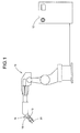
FIG. 1 is a schematic diagram of a robot having a force sensor according to a first embodiment of the present invention. -
FIG. 2 is a plan view of the force sensor. -
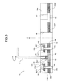
FIG. 3 is an A-A cross-sectional diagram ofFIG. 2 . -
FIG. 4 is a layout drawing of load sensor elements that the force sensor has. -
FIG. 5 is a plan view of a force sensor according to a second embodiment of the present invention. -
FIG. 6 is a B-B cross-sectional diagram ofFIG. 5 . -
FIG. 7 is a schematic diagram illustrating a modification of a preload adjusting unit of the force sensor. -
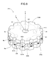
FIG. 8 is a perspective view of a force sensor according to a third embodiment of the present invention. -
FIG. 9 is a plan view of the force sensor. -
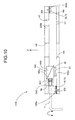
FIG. 10 is an end view of a C-C cross section ofFIG. 9 . - Specific embodiments of the present invention will now be described with reference to the attached drawings for understanding of the present invention. In each drawing, illustration of parts irrelevant to the description (e.g., power line or signal line) may be omitted.
- A
force sensor 10 according to a first embodiment of the present invention is provided on a vertical articulated robot (one example of a robot) 14 to which arobot control device 12 is connected as illustrated inFIG. 1 , for example. More specifically, theforce sensor 10 is mounted on aflange 18 of awrist portion 16 of therobot 14. To the tip side of theforce sensor 10, anend effector 20 is attached. - The
force sensor 10 is a detector for detecting force applied to the end effector 20 (force applied from the outside of the force sensor 10). - As illustrated in
FIG. 2 andFIG. 3 , theforce sensor 10 includes afirst base member 30a, afirst buffer portion 32a, load sensor elements S1 to S4, asecond base member 30b, asecond buffer portion 32b, and apreload adjusting unit 40. - The coordinate system illustrated in
FIG. 2 to FIG. 4 is a rectangular coordinate system having an x-axis, a y-axis, and a z-axis with a coordinate origin O that is the center of theforce sensor 10. - The
first base member 30a is a disk-shaped member, one surface of which is fixed on a flange (one example of a fixed member) 18. - In the
first base member 30a, a plurality of holes H1 for attachment to theflange 18 are formed. In thefirst base member 30a, for example, eight threaded holes H2 for fixing thesecond base member 30b are also formed. - In a central part of the
first base member 30a, a hole H3 through which wiring for an actuator for driving theend effector 20 and a sensor, for example, is passed is formed. - The
first buffer portion 32a is provided between thefirst base member 30a and thesecond base member 30b that is disposed facing the other surface of thefirst base member 30a, and can receive part of an external load applied to each of the load sensor elements S1 to S4 (load in a direction of compressing the load sensor elements S1 to S4). Thefirst buffer portion 32a has an elastic modulus in the thickness direction higher than those of the respective load sensor elements S1 to S4. When a preload is not applied to each of the load sensor elements S1 to S4, the thickness of thefirst buffer portion 32a is larger than the total thickness of each of the load sensor elements S1 to S4 and apressing plate 42 that is disposed on a detector plane of each of the load sensor elements S1 to S4. - The
first buffer portion 32a can be configured to be divided into a first ring-shaped member 32a1 and a second ring-shaped member 32a2 as described below, for example. - The first ring-shaped member 32a1 is a member having a ring shape. The first ring-shaped member 32a1 has an elastic modulus in the thickness direction higher than those of the respective load sensor elements S1 to S4. In addition, the thickness of the first ring-shaped member 32a1 is larger than the total thickness of each of the load sensor elements S1 to S4 and the
pressing plate 42 that is disposed on the detector plane of each of the load sensor elements S1 to S4. In a central part of the first ring-shaped member 32a1, a hole H4 through which wiring for one or more actuators for driving theend effector 20 and one or more sensors, for example, is passed is formed. - The first ring-shaped member 32a1 is disposed on the other surface of the
first base member 30a (the surface on the opposite side of the flange 18) with the hole H3 and the hole H4 aligned. - The second ring-shaped member 32a2 is a member having a ring shape. The second ring-shaped member 32a2 has an elastic modulus in the thickness direction higher than those of the respective load sensor elements S1 to S4. In addition, the thickness of the second ring-shaped member 32a2 is larger than the total thickness of each of the load sensor elements S1 to S4 and the
pressing plate 42 that is disposed on the detector plane of each of the load sensor elements S1 to S4. The thicknesses of the first and the second ring-shaped members 32a1 and 32a2 are substantially the same. - The outer diameters of the second ring-shaped member 32a2 and the
first base member 30a are substantially the same. The second ring-shaped member 32a2 has an inner diameter larger than the outer diameter of the first ring-shaped member 32a1. The second ring-shaped member 32a2 is provided on the other surface (surface opposite to the flange 18) of thefirst base member 30a with the outer periphery thereof aligned with the outer periphery of thefirst base member 30a. The second ring-shaped member 32a2 is disposed outside the first ring-shaped member 32a1. - The
first buffer portion 32a may be configured in an integrated manner. As another example of the first buffer portion, a member in which holes are formed around the respective load sensor elements S1 to S4 or around bolts penetrating may be used. - Each of the load sensor elements S1 to S4 is a detector for detecting the magnitude of force in the Z-axis direction. For example, each of the load sensor elements S1 to S4 is a pressure-sensitive element the electric resistance value of which changes in response to force applied from the outside. By connecting an electric circuit (not illustrated) that outputs a voltage based on the change in electric resistance with each of the load sensor elements S1 to S4 and converting the change in the voltage output by this electric circuit into force, force applied to each of the load sensor elements S1 to S4 can be measured. The relation between voltage and force is obtained in advance by calibration.
- The load sensor elements may be piezoelectric elements that generate voltage in response to force applied from the outside.
- Each of the load sensor elements S1 to S4 is provided on the outer peripheral side of the first ring-shaped member 32a1 and on the inner peripheral side of the second ring-shaped member 32a2, and on the other surface of the
first base member 30a. More specifically, as illustrated inFIG. 2 , the respective load sensor elements S1 to S4 are evenly disposed on substantially the same circumference, and are disposed on the X-axis and the Y-axis when seen in a plan view. - The
second base member 30b is a disk-shaped member, and is disposed facing the other surface of thefirst base member 30a. Thesecond base member 30b can generate a preload to be applied to each of the load sensor elements S1 to S4 toward thefirst base member 30a. - The purpose of applying the preload to each of the load sensor elements S1 to S4 is to detect both of a compressive load (force in the direction of compressing the load sensor elements) and a tensile load (force in the tensile direction opposite to the direction of compressing the load sensor elements).
- In the
second base member 30b, eight countersinks H5 corresponding to the threaded holes H2 formed in thefirst base member 30a are formed. The countersinks H5 are each disposed on the inner side and the outer side of the respective load sensor elements S1 to S4 when seen in a plan view as illustrated inFIG. 2 . - The
second base member 30b is fixed to thefirst base member 30a with the first and the second ring-shaped members 32a1 and 32a2 interposed therebetween by respective bolts BLT1 inserted into the countersinks H5, and generate a preload for each of the load sensor elements S1 to S4. - In a position of the
second base member 30b that faces each of the load sensor elements S1 to S4, a threaded hole H6 is formed in the Z-axis direction (thickness direction). - In positions of the
second base member 30b that face the holes HI, respective holes H7 are formed. Thus, bolts not illustrated are inserted into the holes H7 and the holes H1, whereby theforce sensor 10 is fixed on theflange 18. - Furthermore, in a central part of the
second base member 30b, a hole H8 through which wiring for an actuator for driving theend effector 20 and a sensor, for example, is passed is formed. - The
second buffer portion 32b can receive part of an external load applied in the tensile direction that is opposite to the compressive direction of the respective load sensor elements S1 to S4. - The
second buffer portion 32b (seeFIG. 3 ) has an elastic modulus in the thickness direction higher than those of the respective load sensor elements S1 to S4. To make the thickness of thesecond buffer portion 32b thinner than the thickness of thefirst buffer portion 32a, the value of the elastic modulus of thesecond buffer portion 32b can be set equal to or larger than the value of the elastic modulus of thefirst buffer portion 32a. - The
second buffer portion 32b is constituted by, for example, a plurality of third ring-shaped members 32b1 to 32b8 (seeFIG. 2 andFIG. 3 ). The respective third ring-shaped members 32b1 to 32b8 are inserted into the countersinks H5 formed in thesecond base member 30b as described above, and are interposed between the bolts (one example of a fixation screw) BLT1 and thesecond base member 30b and fixed by the bolts BLT1. - The material of the
second buffer portion 32b may be the same as that of thefirst buffer portion 32a. - By the
first buffer portion 32a and thesecond buffer portion 32b, one example of a buffer body that receives part of a load applied to each of the load sensor elements S1 to S4 from the outside (end effector 20) is constituted. - The
preload adjusting unit 40 can adjust the magnitude of the preload generated by thesecond base member 30b. - The
preload adjusting unit 40 includes a plurality of preload adjusting screws (one example of second adjusting screws) SA1 that advances or retreats along the threaded hole H6 formed in the thickness direction of thesecond base member 30b and thus can press the load sensor elements S1 to S4. By inserting a tool T from the positive direction of the Z-axis to advance or retreat the preload adjusting screws SA1, a preload applied to each of the load sensor elements S1 to S4 via thepressing plate 42 can be adjusted. The purpose of applying a preload to each of the load sensor elements S1 to S4 via thepressing plate 42 is to apply forces that are as equal as possible to respective detector planes of the load sensor elements S1 to S4. - As the preload adjusting screws SA1, for example, hexagon socket set screws (socket set screws) can be used.
- The principle of measuring translational force in each axial direction (three components of translational force) from detection values of the respective load sensor elements S1 to S4 will be described below.
- For example, as illustrated in
FIG. 4 , when a known force is applied to a point P on the end effector 20 (not illustrated inFIG. 4 ), a moment acts around the origin O of the coordinate system. The force applied to the point P can be easily obtained, for example, when parts are assembled by using theend effector 20. - If a distance L from the coordinate origin O to the point P and a distance a from the coordinate origin O to the respective load sensor elements S1 to S4 are known, a force Fx in the X-axis direction can be calculated from output values of the respective load sensor elements S1 to S4. In the same manner, a force Fy in the Y-axis direction can be calculated from the output values of the respective load sensor elements S1 to S4. A force Fz in the Z-axis direction can be calculated from the sum of the output values of the respective load sensor elements S1 to S4.
- Even when an excessively large force is applied to the
force sensor 10, part of the force is received by thefirst buffer portion 32a or thesecond buffer portion 32b, whereby forces received by the respective load sensor elements S1 to S4 are moderated. More specifically, when a compressive load is applied to each of the load sensor elements S1 to S4, the compressive load is divided in the ratio of the elastic modulus between thefirst buffer portion 32a and the load sensor elements S1 to S4. When a tensile load is applied to each of the load sensor elements S1 to S4, the tensile load are divided in the ratio of the elastic modulus between thesecond buffer portion 32b and the load sensor elements S1 to S4. - As described above, because the
force sensor 10 exemplified in the present embodiment has the first and thesecond buffer portions force sensor 10 can be reduced. - Subsequently, a
force sensor 110 according to a second embodiment of the present invention will be described. The same symbols are given to the same components as those of theforce sensor 10 according to the first embodiment, and detailed explanation may be omitted. - The
force sensor 110 according to the present embodiment differs from theforce sensor 10 according to the first embodiment mainly in a preload adjusting unit. - In addition, the shape of a second base member differs from that in the
force sensor 10 according to the first embodiment. Furthermore, the disposition of the respective load sensor elements S1 to S4 differs from that in theforce sensor 10 according to the first embodiment. - This
second base member 130b is disposed facing the other surface of thefirst base member 30a as illustrated inFIG. 5 andFIG. 6 , and can generate a preload to be applied to each of the load sensor elements S1 to S4 toward thefirst base member 30a. - In the
second base member 130b, the countersinks H5 corresponding to the threaded holes H2 formed in thefirst base member 30a are formed. Thesecond base member 130b is fixed to thefirst base member 30a with the first and the second ring-shaped members 32a1 and 32b1 interposed therebetween by the respective bolts BLT1 that are inserted into the countersinks H5 with the third ring-shaped members 32b1 to 32b8 interposed therebetween, and generates a preload. - As illustrated in
FIG. 6 , in thesecond base member 130b, a threaded hole H11 is formed in the direction toward the central part of the second base member (direction intersecting with the thickness direction of thesecond base member 130b). The threaded hole H11 is open to the outer peripheral surface of thesecond base member 130b. - In the positions of the
second base member 130b that face the holes H1, the respective holes H7 are formed. Thus, bolts not illustrated are inserted into the holes H7 and the holes H1, whereby theforce sensor 110 is fixed on theflange 18. - Furthermore, in the central part of the
second base member 130b, the hole H8 through which wiring for an actuator for driving theend effector 20 and a sensor, for example, is passed is formed. - The
preload adjusting unit 140 has a preload adjusting screw (one example of a first adjusting screw) SA2 and a wedge mechanism that is in contact with the preload adjusting screw SA2 and converts a force applied by the preload adjusting screw SA2 into a force compressing each of the load sensor elements S1 to S4. - The preload adjusting screw SA2 advances or retreats along the screw hole H11. The preload adjusting screw SA2 is turned by the tool T inserted from a side surface of the
force sensor 110. As the preload adjusting screw SA2, for example, a hexagon socket set screw (socket set screw) can be used. - The wedge mechanism has a
first adjusting member 140a and asecond adjusting member 140b. - The
first adjusting member 140a is a wedge-shaped member, for example. In thefirst adjusting member 140a, 1) a pressing surface SFa1 for pressing the load sensor element, 2) a pressed surface SFa2 that intersects with the pressing surface SFa1 and is pressed by the preload adjusting screw SA2, and 3) an inclined surface SFa3 that intersects with the pressing surface SFa1 and the pressed surface SFa2 are formed. - The
first adjusting member 140a can move toward the center of theforce sensor 110. - The
second adjusting member 140b is a wedge-shaped member, for example. Thesecond adjusting member 140b is fixed in ahollow portion 142 formed on a surface of thesecond base member 130b on the side facing thefirst base member 30a. On thesecond adjusting member 140b, a contact surface SFb1 that is in contact with the inclined surface SFa3 of thefirst adjusting member 140a is formed. - The
second adjusting member 140b may be configured to be part of thesecond base member 130b. - Operation in adjusting a preload of the
force sensor 110 will be described below. - When an operator turns the preload adjusting screw SA2 using the tool T, the preload adjusting screw SA2 pushes the pressed surface SFa2 of the
first adjusting member 140a. When thefirst adjusting member 140a pushed by the preload adjusting screw SA2 moves on a plane toward the center of theforce sensor 110, the inclined surface SFa3 is pushed by the contact surface SFb1 of thesecond adjusting member 140b toward thefirst base member 30a. As a result, the pressing surface SFa1 of thefirst adjusting member 140a pushes the load sensor element S3 via the pressing plate 42 (in the same manner also for the load sensor elements S1, S2, and S4). - In other words, when the operator turns the tool T, the preload for the load sensor element is adjusted.
- As illustrated in
FIG. 7 , the wedge mechanism may have athird adjusting member 141a in a wedge shape pressed by the preload adjusting screw SA2 and afourth adjusting member 141b in a wedge shape disposed between thethird adjusting member 141a and the load sensor element S3 to constitute part of apreload adjusting unit 141. - When the preload adjusting screw SA2 is turned, the
third adjusting member 141a moves on the XY plane toward the center of theforce sensor 110, and the fourth adjustingmember 141b pushes the load sensor element S3. Thus, thepreload adjusting unit 141 can adjust the preload of the load sensor element S3. - As describe above, because the
force sensor 110 exemplified in the present embodiment has the first and thesecond buffer portions end effector 20 provided on the tip side. Furthermore, the thickness of theforce sensor 110 can be reduced. - Subsequently, a
force sensor 210 according to a third embodiment of the present invention will be described. The same symbols are given to the same components as those of theforce sensors - The
force sensor 210 according to the present embodiment differs from theforce sensor 110 according to the second embodiment mainly in a buffer body. In addition, the shapes of first and the second base members differ from those in theforce sensor 110 according to the second embodiment. - The buffer body is provided between this
first base member 230a and thissecond base member 230b, and can receive part of a load applied to each of the load sensor elements S1 to S4 from the outside. As illustrated inFIG. 8 , the buffer body is a ring-shapedspring member 300 both surfaces of which are bent in a direction intersecting with a radial direction to alternately and repeatedly formconcave portions 300a andconvex portions 300b in the circumferential direction. Theconcave portions 300a are fixed on an outer peripheral portion of thefirst base member 230a with bolts BLTa, and theconvex portions 300b are fixed on an outer peripheral portion of thesecond base member 230b with bolts BLTb. - The
spring member 300 has an elastic modulus in the thickness direction (central-axis direction intersecting with the radial direction) higher than those of the load sensor elements S1 to S4. - The
spring member 300 is a wave spring, for example. - In the
first base member 230a, notches Na for inserting a tool for fastening the bolts BLTb are formed in the outer peripheral portion. - In the
second base member 230b, notches Nb for inserting a tool for fastening the bolts BLTa are formed in the outer peripheral portion. - As illustrated in
FIG. 10 , thepreload adjusting unit 140 is configured to be substantially the same as the preload adjusting unit exemplified in the second embodiment. However, the threaded hole H11 through which the preload adjusting screw SA2 advances and retreats is formed in thesecond base member 230b in a direction from a central part of theforce sensor 210 toward the corresponding bolt BLTa when seen in a plan view (seeFIG. 9 ). The threaded hole H11 is formed in the direction from the central part of theforce sensor 210 toward the corresponding bolt BLTa, whereby the tool T for turning the preload adjusting screw SA2 can be prevented from interfering with thespring member 300. - The threaded hole H11 only has to be disposed in a position where the tool T for turning the preload adjusting screw SA2 does not interfere with the
spring member 300, and can also be formed in a direction from the central part of theforce sensor 210 toward the corresponding bolt BLTb, for example. - The preload adjusting unit herein may include the preload adjusting screws SA1 each of which advances or retreats along the threaded hole H6 formed in the thickness direction of the second base member and thus can press each of the load sensor elements S1 to S4 as exemplified in the first embodiment.
- As described above, because the
force sensor 210 exemplified in the present embodiment has thespring member 300, loads applied to the load sensor elements S1 to S4 can be suppressed. In addition, preloads applied to the respective load sensor elements S1 to S4 can each be independently adjusted without removing theend effector 20 provided on the tip side. Furthermore, the number of components can be reduced and thus the thickness can be reduced in comparison with the cases of theforce sensors - The present invention is not limited to the above-described embodiments, and can be modified within a range not departing from the gist of the present invention. For example, cases of combining part or all of the above-described embodiments and modifications thereof to constitute the invention are included in the technical scope of the present invention.
- The force sensor may be integrated in a wrist portion of the robot, for example. Furthermore, the force sensor can be provided to a mechanical device other than a robot. Examples of the other mechanical device include a machine tool.
- The number and the disposition of the respective load sensor elements are not limited to those in the above-described embodiments, and can be changed as appropriate.
-
- 10
- Force sensor
- 12
- Robot control device
- 14
- Vertical articulated robot
- 16
- Wrist portion
- 18
- Flange
- 20
- End effector
- 30a
- First base member
- 30b
- Second base member
- 32a
- First buffer portion
- 32a1
- First ring-shaped member
- 32a2
- Second ring-shaped member
- 32b
- Second buffer portion
- 32b1 to 32b8
- Third ring-shaped members
- 40
- Preload adjusting unit
- 42
- Pressing plate
- 110
- Force sensor
- 130b
- Second base member
- 140
- Preload adjusting unit
- 140a
- First adjusting member
- 140b
- Second adjusting member
- 141
- Preload adjusting unit
- 141a
- Third adjusting member
- 141b
- Fourth adjusting member
- 142
- Hollow portion
- 210
- Force sensor
- 230a
- First base member
- 230b
- Second base member
- 300
- Spring member
- 300a
- Concave portions
- 300b
- Convex portions
- BLT1
- Bolts
- BLTa
- Bolts
- BLTb
- Bolts
- H1
- Holes
- H2
- Threaded holes
- H3
- Hole
- H4
- Hole
- H5
- Countersinks
- H6
- Threaded hole
- H7
- Holes
- H8
- Hole
- H11
- Threaded hole
- Na, Nb
- Notches
- S1 to S4
- Load sensor elements
- SA1, SA2
- Preload adjusting screws
- SFa1
- Pressing surface
- SFa2
- Pressed surface
- SFa3
- Inclined surface
- SFb1
- Contact surface
- T
- Tool
Claims (9)
- A force sensor comprising:a first base member one surface of which is fixed on a fixed member;a plurality of load sensor elements that is provided on another surface of the first base member to detect a load;a second base member that is disposed facing the other surface of the first base member to generate a preload to be applied to each of the load sensor elements toward the first base member;a preload adjusting unit that adjusts magnitude of the preload generated by the second base member; anda buffer body that receives a part of an external load to be applied to each of the load sensor elements from outside.
- The force sensor according to claim 1, wherein the preload adjusting unit includes:a first adjusting screw that advances or retreats along a threaded hole that is formed in a direction toward a central part of the second base member and is open to an outer peripheral surface of the second base member; anda wedge mechanism that is in contact with the first adjusting screw to convert a force applied by the first adjusting screw into a force compressing each of the load sensor elements.
- The force sensor according to claim 2, wherein the wedge mechanism includes:a first adjusting member including a pressing surface for pressing the load sensor element, a pressed surface that intersects with the pressing surface and is pressed by the first adjusting screw, and an inclined surface that intersects with the pressing surface and the pressed surface; anda second adjusting member that is provided on a surface of the second base member facing the first base member and of which a contact surface is in contact with the inclined surface.
- The force sensor according to claim 1, wherein the preload adjusting unit includes a plurality of second adjusting screws that advances or retreats along a threaded hole formed in a thickness direction of the second base member and presses the load sensor elements.
- The force sensor according to any one of claims 2 to 4, wherein the buffer body includes:a first buffer portion that receives a part of the external load applied in a direction of compressing the load sensor elements; anda second buffer portion that receives a part of the external load applied in a tensile direction opposite to the direction of compressing the load sensor elements.
- The force sensor according to claim 5, wherein
the first buffer portion is a member provided between the first base member and the second base member, and having an elastic modulus in a thickness direction higher than an elastic modulus of each of the load sensor elements, and
the second buffer portion is a member provided between the second base member and a fixation screw for fixing the second base member to the first base member, and having an elastic modulus in the thickness direction higher than the elastic modulus of each of the load sensor elements. - The force sensor according to claim 6, wherein
the first buffer portion includes a first ring-shaped member and a second ring-shaped member having an inner diameter larger than an outer diameter of the first ring-shaped member, and
the load sensor elements are disposed on an outer peripheral side of the first ring-shaped member and on an inner peripheral side of the second ring-shaped member. - The force sensor according to any one of claims 2 to 4, wherein
the buffer body includes a ring-shaped spring member both surfaces of which are bent in a direction intersecting with a radial direction to alternately and repeatedly form concave portions and convex portions in a circumferential direction, and
the concave portions are fixed on the first base member and the convex portions are fixed on the second base member. - A robot comprising:a force sensor mounted on a flange of a wrist portion; andan end effector attached to a tip side of the force sensor,the force sensor comprising:a first base member one surface of which is fixed on the flange;a plurality of load sensor elements that is provided on another surface of the first base member to detect a load;a second base member that is disposed facing the other surface of the first base member to generate a preload to be applied to each of the load sensor elements toward the first base member;a preload adjusting unit that adjusts magnitude of the preload generated by the second base member; anda buffer body that receives a part of an external load to be applied to each of the load sensor elements from the end effector.
Applications Claiming Priority (1)
| Application Number | Priority Date | Filing Date | Title |
|---|---|---|---|
| PCT/JP2011/069941 WO2013031007A1 (en) | 2011-09-01 | 2011-09-01 | Force sensor and robot |
Publications (1)
| Publication Number | Publication Date |
|---|---|
| EP2752650A1 true EP2752650A1 (en) | 2014-07-09 |
Family
ID=47755555
Family Applications (1)
| Application Number | Title | Priority Date | Filing Date |
|---|---|---|---|
| EP11871463.3A Withdrawn EP2752650A1 (en) | 2011-09-01 | 2011-09-01 | Force sensor and robot |
Country Status (4)
| Country | Link |
|---|---|
| US (1) | US20140174239A1 (en) |
| EP (1) | EP2752650A1 (en) |
| CN (1) | CN103765181A (en) |
| WO (1) | WO2013031007A1 (en) |
Cited By (6)
| Publication number | Priority date | Publication date | Assignee | Title |
|---|---|---|---|---|
| US10670479B2 (en) | 2018-02-27 | 2020-06-02 | Methode Electronics, Inc. | Towing systems and methods using magnetic field sensing |
| US10696109B2 (en) | 2017-03-22 | 2020-06-30 | Methode Electronics Malta Ltd. | Magnetolastic based sensor assembly |
| US11084342B2 (en) | 2018-02-27 | 2021-08-10 | Methode Electronics, Inc. | Towing systems and methods using magnetic field sensing |
| US11135882B2 (en) | 2018-02-27 | 2021-10-05 | Methode Electronics, Inc. | Towing systems and methods using magnetic field sensing |
| US11221262B2 (en) | 2018-02-27 | 2022-01-11 | Methode Electronics, Inc. | Towing systems and methods using magnetic field sensing |
| US11491832B2 (en) | 2018-02-27 | 2022-11-08 | Methode Electronics, Inc. | Towing systems and methods using magnetic field sensing |
Families Citing this family (13)
| Publication number | Priority date | Publication date | Assignee | Title |
|---|---|---|---|---|
| JP6089843B2 (en) * | 2013-03-21 | 2017-03-08 | セイコーエプソン株式会社 | Force detection device, robot and device |
| JPWO2016132868A1 (en) * | 2015-02-17 | 2017-11-24 | Nok株式会社 | Tactile sensor covering structure and tactile sensor |
| DE102015005759A1 (en) * | 2015-05-05 | 2015-12-03 | Daimler Ag | Method and device for joining at least two components |
| US10239213B1 (en) * | 2015-11-24 | 2019-03-26 | X Development Llc | Flexure assembly for force/torque sensing |
| EP3526565A1 (en) * | 2016-10-17 | 2019-08-21 | Kistler Holding AG | Force and torque sensor, force transducer module for such a force and torque sensor and robot having such a force and torque sensor |
| CN110462357B (en) * | 2017-08-25 | 2022-01-25 | 非夕机器人有限公司 | High reliability torque sensor with moderate flexibility |
| US10732061B2 (en) | 2017-09-07 | 2020-08-04 | X Development Llc | Unibody flexure design for displacement-based force/torque sensing |
| JP7038320B2 (en) * | 2017-12-22 | 2022-03-18 | ムネカタインダストリアルマシナリー株式会社 | Pressure sensor |
| US11014417B2 (en) | 2018-02-27 | 2021-05-25 | Methode Electronics, Inc. | Towing systems and methods using magnetic field sensing |
| CN108942945B (en) * | 2018-08-22 | 2024-05-17 | 深圳市启玄科技有限公司 | Robot-based touch control method and touch control assembly |
| JP7127513B2 (en) * | 2018-11-30 | 2022-08-30 | トヨタ自動車株式会社 | Sensor system and robot hand |
| US20220227011A1 (en) * | 2019-06-06 | 2022-07-21 | Omron Corporation | Tactile Sensor, Robot Hand, and Robot |
| DE102019215294B4 (en) | 2019-10-04 | 2022-12-22 | Dr. Doll Engineering Gmbh | Robotic force measuring device |
Family Cites Families (15)
| Publication number | Priority date | Publication date | Assignee | Title |
|---|---|---|---|---|
| US3854328A (en) * | 1973-01-18 | 1974-12-17 | Chevron Res | Resiliency testing device |
| DE3680341D1 (en) * | 1986-11-07 | 1991-08-22 | Kristal Instr Ag | MULTI-COMPONENT DYNAMOMETER. |
| DE3877573D1 (en) * | 1988-09-30 | 1993-02-25 | Kistler Instrumente Ag | MEASURING PLATFORM. |
| JPH07146190A (en) * | 1993-11-19 | 1995-06-06 | Yaskawa Electric Corp | Force detector |
| US5991676A (en) * | 1996-11-22 | 1999-11-23 | Breed Automotive Technology, Inc. | Seat occupant sensing system |
| JP3053606B2 (en) * | 1998-02-23 | 2000-06-19 | ファナック株式会社 | Method of calibrating force sensor mounted on robot and robot |
| JP3400377B2 (en) * | 1999-03-10 | 2003-04-28 | 富士通株式会社 | Foot sensor and humanoid robot having the same |
| US6532830B1 (en) * | 1999-09-20 | 2003-03-18 | Ut-Battelle, Llc | High payload six-axis load sensor |
| JP4779246B2 (en) * | 2001-06-28 | 2011-09-28 | トヨタ自動車株式会社 | Tire acting force detection device |
| KR100499143B1 (en) * | 2003-02-27 | 2005-07-04 | 삼성전자주식회사 | Ground reaction force detection module for walking robot and robot foot structure adopting the same |
| JP4223300B2 (en) * | 2003-03-10 | 2009-02-12 | 株式会社ジェイテクト | Bearings for automobile wheels |
| JP2005017253A (en) * | 2003-06-30 | 2005-01-20 | Toyoda Mach Works Ltd | Five component force meter device |
| JP4347165B2 (en) | 2004-09-02 | 2009-10-21 | 株式会社豊田中央研究所 | Multi-axis force sensor |
| JP4687737B2 (en) * | 2008-03-25 | 2011-05-25 | 株式会社デンソー | Load sensor |
| US7743672B2 (en) * | 2008-06-06 | 2010-06-29 | Kulite Semiconductor Products, Inc. | Multiple axis load cell controller |
-
2011
- 2011-09-01 EP EP11871463.3A patent/EP2752650A1/en not_active Withdrawn
- 2011-09-01 WO PCT/JP2011/069941 patent/WO2013031007A1/en not_active Ceased
- 2011-09-01 CN CN201180073110.5A patent/CN103765181A/en active Pending
-
2014
- 2014-02-28 US US14/193,369 patent/US20140174239A1/en not_active Abandoned
Non-Patent Citations (1)
| Title |
|---|
| See references of WO2013031007A1 * |
Cited By (7)
| Publication number | Priority date | Publication date | Assignee | Title |
|---|---|---|---|---|
| US10696109B2 (en) | 2017-03-22 | 2020-06-30 | Methode Electronics Malta Ltd. | Magnetolastic based sensor assembly |
| US10940726B2 (en) | 2017-03-22 | 2021-03-09 | Methode Electronics Malta Ltd. | Magnetoelastic based sensor assembly |
| US10670479B2 (en) | 2018-02-27 | 2020-06-02 | Methode Electronics, Inc. | Towing systems and methods using magnetic field sensing |
| US11084342B2 (en) | 2018-02-27 | 2021-08-10 | Methode Electronics, Inc. | Towing systems and methods using magnetic field sensing |
| US11135882B2 (en) | 2018-02-27 | 2021-10-05 | Methode Electronics, Inc. | Towing systems and methods using magnetic field sensing |
| US11221262B2 (en) | 2018-02-27 | 2022-01-11 | Methode Electronics, Inc. | Towing systems and methods using magnetic field sensing |
| US11491832B2 (en) | 2018-02-27 | 2022-11-08 | Methode Electronics, Inc. | Towing systems and methods using magnetic field sensing |
Also Published As
| Publication number | Publication date |
|---|---|
| WO2013031007A1 (en) | 2013-03-07 |
| CN103765181A (en) | 2014-04-30 |
| US20140174239A1 (en) | 2014-06-26 |
Similar Documents
| Publication | Publication Date | Title |
|---|---|---|
| US20140174239A1 (en) | Force sensor and robot | |
| KR101293984B1 (en) | Strain gauge type force-torque sensor and method for manufacturing the same | |
| US9696229B2 (en) | Precision force applicator for force transducer calibration | |
| JP5248221B2 (en) | Force sensor and assembly method thereof | |
| US10739216B2 (en) | Torque sensor with a radially elastic torque transfer | |
| JP5606662B2 (en) | Torque sensor and motor with torque sensor | |
| CN103313846B (en) | Electric cylinder and electric cylinder system | |
| KR102183179B1 (en) | Multi-axis force-torque sensor using straingauges | |
| KR20130103431A (en) | Sensor module, force detecting device, and robot | |
| US11105694B2 (en) | Torque sensor having a sealing membrane | |
| TWI818989B (en) | Torque sensor | |
| US20130283942A1 (en) | Connecting rod for aeronautical mechanism and aeronautical mechanism comprising such a connecting rod | |
| TWI811395B (en) | Installation structure of torque sensor | |
| US10976208B2 (en) | Force sensor | |
| CN102501245A (en) | Intermediate branch chain of fully-flexible fine operation platform | |
| US20220178772A1 (en) | Strain sensor fixing device and torque sensor using the same | |
| KR20130049918A (en) | 6-axis force-torque sensor for measuring electrostatic capacity | |
| JP2012047622A (en) | Shaft center adjusting device for material testing machine | |
| JP4877665B2 (en) | 3-axis force sensor | |
| JPWO2013031007A1 (en) | Force sensor and robot | |
| US20220187147A1 (en) | Strain sensor fixing device and torque sensor using same | |
| JP2023163991A (en) | force sensor module | |
| Wang et al. | Static Calibration Structure Design of 6D Force Sensor | |
| JP2005134219A (en) | Axis grip sensor | |
| CN120232560A (en) | Elastic body and force sensor of force sensor |
Legal Events
| Date | Code | Title | Description |
|---|---|---|---|
| PUAI | Public reference made under article 153(3) epc to a published international application that has entered the european phase |
Free format text: ORIGINAL CODE: 0009012 |
|
| 17P | Request for examination filed |
Effective date: 20140227 |
|
| AK | Designated contracting states |
Kind code of ref document: A1 Designated state(s): AL AT BE BG CH CY CZ DE DK EE ES FI FR GB GR HR HU IE IS IT LI LT LU LV MC MK MT NL NO PL PT RO RS SE SI SK SM TR |
|
| DAX | Request for extension of the european patent (deleted) | ||
| STAA | Information on the status of an ep patent application or granted ep patent |
Free format text: STATUS: THE APPLICATION HAS BEEN WITHDRAWN |
|
| 18W | Application withdrawn |
Effective date: 20141208 |