EP2752582A1 - Impeller, rotary machine with impeller, and method for manufacturing impeller - Google Patents
Impeller, rotary machine with impeller, and method for manufacturing impeller Download PDFInfo
- Publication number
- EP2752582A1 EP2752582A1 EP11869760.6A EP11869760A EP2752582A1 EP 2752582 A1 EP2752582 A1 EP 2752582A1 EP 11869760 A EP11869760 A EP 11869760A EP 2752582 A1 EP2752582 A1 EP 2752582A1
- Authority
- EP
- European Patent Office
- Prior art keywords
- impeller
- blades
- end side
- shroud
- disc
- Prior art date
- Legal status (The legal status is an assumption and is not a legal conclusion. Google has not performed a legal analysis and makes no representation as to the accuracy of the status listed.)
- Withdrawn
Links
- 238000004519 manufacturing process Methods 0.000 title claims description 29
- 238000000034 method Methods 0.000 title claims description 21
- 230000002093 peripheral effect Effects 0.000 claims description 44
- 239000000463 material Substances 0.000 claims description 12
- 238000005520 cutting process Methods 0.000 claims description 5
- 238000003754 machining Methods 0.000 description 32
- 239000012530 fluid Substances 0.000 description 12
- 238000009760 electrical discharge machining Methods 0.000 description 8
- 230000006835 compression Effects 0.000 description 3
- 238000007906 compression Methods 0.000 description 3
- 238000005242 forging Methods 0.000 description 3
- 238000011144 upstream manufacturing Methods 0.000 description 2
- 238000003466 welding Methods 0.000 description 2
- OKTJSMMVPCPJKN-UHFFFAOYSA-N Carbon Chemical compound [C] OKTJSMMVPCPJKN-UHFFFAOYSA-N 0.000 description 1
- RYGMFSIKBFXOCR-UHFFFAOYSA-N Copper Chemical compound [Cu] RYGMFSIKBFXOCR-UHFFFAOYSA-N 0.000 description 1
- 238000005219 brazing Methods 0.000 description 1
- 238000001816 cooling Methods 0.000 description 1
- 229910052802 copper Inorganic materials 0.000 description 1
- 239000010949 copper Substances 0.000 description 1
- 230000000694 effects Effects 0.000 description 1
- 229910002804 graphite Inorganic materials 0.000 description 1
- 239000010439 graphite Substances 0.000 description 1
- 229910001220 stainless steel Inorganic materials 0.000 description 1
- 239000010935 stainless steel Substances 0.000 description 1
Images



Classifications
-
- F—MECHANICAL ENGINEERING; LIGHTING; HEATING; WEAPONS; BLASTING
- F04—POSITIVE - DISPLACEMENT MACHINES FOR LIQUIDS; PUMPS FOR LIQUIDS OR ELASTIC FLUIDS
- F04D—NON-POSITIVE-DISPLACEMENT PUMPS
- F04D29/00—Details, component parts, or accessories
- F04D29/18—Rotors
- F04D29/22—Rotors specially for centrifugal pumps
- F04D29/2261—Rotors specially for centrifugal pumps with special measures
- F04D29/2277—Rotors specially for centrifugal pumps with special measures for increasing NPSH or dealing with liquids near boiling-point
-
- F—MECHANICAL ENGINEERING; LIGHTING; HEATING; WEAPONS; BLASTING
- F04—POSITIVE - DISPLACEMENT MACHINES FOR LIQUIDS; PUMPS FOR LIQUIDS OR ELASTIC FLUIDS
- F04D—NON-POSITIVE-DISPLACEMENT PUMPS
- F04D29/00—Details, component parts, or accessories
- F04D29/26—Rotors specially for elastic fluids
- F04D29/28—Rotors specially for elastic fluids for centrifugal or helico-centrifugal pumps for radial-flow or helico-centrifugal pumps
-
- F—MECHANICAL ENGINEERING; LIGHTING; HEATING; WEAPONS; BLASTING
- F04—POSITIVE - DISPLACEMENT MACHINES FOR LIQUIDS; PUMPS FOR LIQUIDS OR ELASTIC FLUIDS
- F04D—NON-POSITIVE-DISPLACEMENT PUMPS
- F04D29/00—Details, component parts, or accessories
- F04D29/02—Selection of particular materials
- F04D29/023—Selection of particular materials especially adapted for elastic fluid pumps
-
- F—MECHANICAL ENGINEERING; LIGHTING; HEATING; WEAPONS; BLASTING
- F04—POSITIVE - DISPLACEMENT MACHINES FOR LIQUIDS; PUMPS FOR LIQUIDS OR ELASTIC FLUIDS
- F04D—NON-POSITIVE-DISPLACEMENT PUMPS
- F04D29/00—Details, component parts, or accessories
- F04D29/26—Rotors specially for elastic fluids
- F04D29/28—Rotors specially for elastic fluids for centrifugal or helico-centrifugal pumps for radial-flow or helico-centrifugal pumps
- F04D29/284—Rotors specially for elastic fluids for centrifugal or helico-centrifugal pumps for radial-flow or helico-centrifugal pumps for compressors
-
- F—MECHANICAL ENGINEERING; LIGHTING; HEATING; WEAPONS; BLASTING
- F04—POSITIVE - DISPLACEMENT MACHINES FOR LIQUIDS; PUMPS FOR LIQUIDS OR ELASTIC FLUIDS
- F04D—NON-POSITIVE-DISPLACEMENT PUMPS
- F04D29/00—Details, component parts, or accessories
- F04D29/60—Mounting; Assembling; Disassembling
- F04D29/601—Mounting; Assembling; Disassembling specially adapted for elastic fluid pumps
-
- Y—GENERAL TAGGING OF NEW TECHNOLOGICAL DEVELOPMENTS; GENERAL TAGGING OF CROSS-SECTIONAL TECHNOLOGIES SPANNING OVER SEVERAL SECTIONS OF THE IPC; TECHNICAL SUBJECTS COVERED BY FORMER USPC CROSS-REFERENCE ART COLLECTIONS [XRACs] AND DIGESTS
- Y10—TECHNICAL SUBJECTS COVERED BY FORMER USPC
- Y10T—TECHNICAL SUBJECTS COVERED BY FORMER US CLASSIFICATION
- Y10T29/00—Metal working
- Y10T29/49—Method of mechanical manufacture
- Y10T29/49316—Impeller making
- Y10T29/49332—Propeller making
Definitions
- the present invention relates to an impeller in rotary machines, such as a centrifugal compressor, a rotary machine including the impeller, and a method for manufacturing the impeller.
- rotary machines such as a centrifugal compressor, a rotary machine including the impeller, and a method for manufacturing the impeller.
- an impeller 101 used for rotary machines has a fixed hub portion 112 of a rotating shaft S, a disc-shaped disc 107 that is provided integrally with the hub portion 112, a shroud 108 that is arranged so as to be spaced apart from the disc 107 in the axial direction of the central axis L, and a plurality of blades 106 that are provided in a circumferential direction and connect the disc 107 to the shroud 108.
- a portion surrounded by the side surfaces of the blades 106 and two mutually facing surfaces of the disc 107 and the shroud 108 formed a flow passage 103 for compressing air. Additionally, by shrink-fitting the hub portion 112 to the rotating shaft S of the rotary machine, the impeller 101 is fixed to the rotating shaft S.
- the flow passage 103 opens toward a first end side of the central axis L on the inner peripheral side, curves gradually so as to be directed to a radial outer peripheral side, and opens toward the radial direction on outer peripheral side. That is, the flow passage 103 is formed in a curved shape as viewed from the circumferential direction in order to direct a fluid, which is introduced from the first end side along a second end side, to the radial outer peripheral side (particularly, refer to FIG 14 ). Moreover, as shown in FIG. 13 , as the blades 106 are obliquely connected to the disc 107, the compression performance of the impeller 101 is improved, and thereby, the flow passage 103 assumes a complicated three-dimensional shape.
- the impeller 101 As a method for manufacturing the impeller 101, a method in which the blades 106 and one of the disc 107 and the shroud 108 are integrally formed, the other of the disc and shroud is separately manufactured, and these disc and shroud are integrated by welding or brazing, is known. Additionally, since the impeller requires high rigidity, a one-piece impeller with high strength reliability is manufactured by shaving out the disc 107, the shroud 108, and the blade 106 from a single base material (for example, refer to PTL 1).
- the flow passage 103 of the impeller 101 has a complicated shape having a curved portion, and the inside of the flow passage is narrow. Therefore, during the manufacture of the one-piece impeller 101, it is necessary to perform complicated cutting while inserting, for example, machining members, such as an electrode for machining, from positions to be used as an inlet and an outlet of the flow passage 103. Additionally, in the manufacturing method as described in PTL 1, it is necessary to form the flow passage using a special machining member and substantial manufacturing costs are incurred.
- the present invention has been made in consideration of such a situation, and an object thereof is to provide an impeller, a rotary machine including the impeller, and a method for manufacturing the impeller that maintains the performance of the related art while being capable of being manufactured at low cost.
- an impeller related to a first aspect of the present invention is an impeller including a plurality of blades disposed in a circumferential direction of the impeller, in which each of the blades directs outward from inward in a radial direction of the impeller; a shroud located close to a first end side of an axis of the impeller with respect to the blades, and to which the blades are attached; and a disk located close to a second end side of an axis of the impeller with respect to the blades, to which the blades are attached, and configured to be attached to a rotating shaft.
- a plurality of flow passages are formed by the blades, the disc, and the shroud.
- the blades, the shroud and a first portion of the disk close to the second end side of the axis of the impeller are integrated so as to form a first member.
- a second portion of the disk close to the first end side of the axis of the impeller forms a second member.
- the accessibility of the machining tool improves. That is, when the machining tool is inserted from a position to be used as the outlet of the flow passage, the machining when forming the flow passage becomes easy by making a part that becomes an interference object, on the inner peripheral side, into a separate second member. Additionally, when the machining tool is inserted from a position to be used as the introduction port that is the inlet of the flow passage, the machining of the introduction port becomes easy by making a part that becomes an interference object into a separate second member. Thereby, the manufacturing time can be shortened, and the manufacturing costs can be kept down.
- At least one of mutually facing surfaces of the disc and the shroud in the first member is formed into a flat surface.
- the shape of the flow passage defined by the disc, the shroud, and the blades are further simplified. Therefore, the accessibility of the machining tool can be improved and the man-hours of machining when forming the flow passage can be further reduced.
- both of the mutually facing surfaces of the disc and the shroud in the first member are formed into flat surfaces.
- a curved portion is eliminated in a cross-sectional shape when viewed from the circumferential direction in the shape of the flow passage defined by the disc, the shroud, and the blades. Therefore, the man-hours of machining when forming the flow passage can be further reduced.
- the blades are provided within a range of the flat surface of the disc or the shroud as viewed from the axial direction.
- the shape of the flow passage defined by the disc, the shroud, and the blades are further simplified. Therefore, the accessibility of the machining tool can be improved and the man-hours of machining when forming the flow passage can be further reduced.
- the surface of the second member that faces the first end side is formed in a curved shape so as to be directed to the radial outer peripheral side as it goes from the first end side to the second end side.
- a fluid introduced into the impeller can be guided to the flow passage without any delay by the surface of the second member that faces the first end side. This can maintain the compression performance of the impeller.
- the first member in the impeller of any one aspect of the first to fifth aspects, has a fixed portion that is fixed to the rotating shaft.
- the impeller can be more firmly fixed to the rotating shaft compared to a case where the second member equivalent to a hub portion of a disc of the related art is fixed to the rotating shaft after the first member and the second member are integrated. That is, the impeller can be more firmly fixed to the rotating shaft by directly fixing the first member, which has a weight more than the second member, to the rotating shaft.
- the surface of the blade that forms the flow passage is formed so as to be orthogonal to the surface of the disc that faces the shroud.
- the shape of the blade is further simplified as compared to a shape where the surface of the blade that forms the flow passage inclines with respect to the disc. Therefore, the man-hours of machining when forming the flow passage can be further reduced.
- an eighth aspect of the present invention provides a rotary machine including the impeller related to any one aspect of the first to seventh aspects.
- the rotary machine can be provided at low costs.
- a method for manufacturing an impeller related to a ninth aspect of the present invention is a method for manufacturing an impeller including a plurality of blades disposed in a circumferential direction of the impeller, in which each of the blades directs outward from inward in a radial direction of the impeller; a shroud located close to a first end side of an axis of the impeller with respect to the blades, and to which the blades are attached; and a disk located close to a second end side of an axis of the impeller with respect to the blades, to which the blades are attached, a plurality of flow passages being formed by the blades, the disc, and the shroud.
- the method for manufacturing an impeller includes a first member forming step of performing cutting on a base material for forming the second end side of the axis of the impeller to form the flow passages, and forming a first member in which the blades, the shroud, and a first portion of the disc close to the second end side of the impeller are integrally formed; and a second member forming step of forming a second member that constitutes a second portion of the disc close to the first end side of the impeller.
- the second member formed in the second member forming step is made into a part that constitutes the portion of the disc on the first end side.
- the machining tool when the machining tool is inserted from a position to be used as the introduction port that is the inlet of the flow passage, the machining of the introduction port becomes easy by making a part that becomes an interference object into a separate second member. Thereby, the manufacturing time can be shortened, and the manufacturing costs can be kept down.
- the surface of the second member that faces the first end side is formed with a curved portion that is directed to the radial outer peripheral side as it goes from the first end side to the second end side.
- the air introduced into the impeller including the second member formed by the second member forming step can be guided to the flow passage without any delay by the surface of the second member that faces the first end side. Therefore, the performance of the impeller does not degrade.
- the accessibility of a machining tool improves when a flow passage portion of the impeller is formed. Therefore, the manufacturing time can be shortened and the manufacturing costs can be kept down.
- a centrifugal compressor 50 is shown as an example of a rotary machine of the present embodiment in FIG. 1 .
- the centrifugal compressor 50 is mainly constituted by a rotating shaft S that is rotated around an axis P, impellers 1 that are attached to the shaft S and compress a fluid utilizing centrifugal force, and a casing 53 that rotatably supports the rotating shaft S and is formed with flow passages 52 that allow the fluid to flow therethrough from the upstream to the downstream.
- the casing 53 is formed so as to form a substantially columnar outline, and the rotating shaft S is arranged so as to pass through the center of the casing.
- Journal bearings 54 are provided at both axial ends of the rotating shaft S of the casing 53, and a thrust bearing 55 is provided at one end of the rotating shaft.
- the journal bearings 54 and the thrust bearing 55 rotatably support the rotating shaft S. That is, the rotating shaft S is supported by the casing 53 via the journal bearings 54 and the thrust bearing 55.
- a suction port 56 into which a fluid is made to flow from the outside is provided on one end side of the casing 53 in the axial direction, and a discharge port 57 through which the fluid flows out to the outside is provided on the other end side.
- An internal space which communicates with the suction port 56 and the discharge port 57, respectively, and repeats diameter reduction and diameter increase, is provided within the casing 53.
- This internal space functions as a space that accommodates the impeller 1, and also functions as the above flow passages 52. That is, the suction port 56 and the discharge port 57 communicate with each other via the impellers 1 and the flow passages 52.
- a plurality of impellers 1 is arranged at intervals in the axial direction of the rotating shaft S.
- six impellers 1 are provided in the illustrated example, at least one or more impellers may be provided.
- the impeller 1 has a substantially disc shape, and is configured so that a fluid suctioned from an introduction port 2 that opens to a first side in the direction (hereinafter referred to as an axial direction) of a central axis L is discharged toward the radial outer peripheral side via flow passages 3 formed inside the impeller 1.
- outer peripheral side of the impeller 1 in the radial direction is simply referred to as outer peripheral side.
- inner peripheral side of the impeller 1 in the radial direction is simply referred to as inner peripheral side.
- the upper side of FIGS. 2 and 4 that becomes the upstream side of the fluid is referred to as a first end side, and the lower side of FIGS. 2 and 4 that becomes the downstream side of the fluid is referred to as a second end side.
- the impeller 1 of the present embodiment is equipped with a substantially disc-shaped first member 4 that forms the second end side, and a substantially cylindrical second member 5 that forms the first end side and that has an outer peripheral surface that is gradually increased in diameter toward the second end side.
- a disc 7 that is fixed to the rotating shaft S in the impeller 1, a plurality of blades 6 that are provided in the circumferential direction on the first end side of the disc 7 so as to be directed from the inner peripheral side to the outer peripheral side, and a shroud 8 that is provided to face the disc 7 on the first end side and is attached to the blades 6 are constituted by the first member 4 and the second member 5.
- the first member 4 and the second member 5 are not fixed to each other in the present embodiment but are fixed to the rotating shaft S, respectively, whereby the introduction port 2 is defined between the first member 4 and the second member 5, and the first member 4 and the second member 5 further defines a suction portion 9 that connects the introduction port 2 and the flow passages 3.
- the first member 4 is arranged from the radial inner peripheral side toward the radial outer peripheral side.
- the first member 4 is equipped with a plurality of blades 6 disposed in a circumferential direction of the impeller, a first portion 7a that is provided on the second end side of the blades 6 and constitutes the second end side of the disc 7 to which the blades 6 are attached, and the shroud 8 that is provided on the first end side of the blades 6 and has the blades 6 attached thereto. That is, the shroud 8 is arranged so as to be spaced apart from the first portion 7a of the disc 7 by a predetermined distance.
- the first member 4 is formed from, for example, precipitation-hardened stainless steel.
- the first portion 7a of the disc 7 includes a fixed portion 12 that is fixed to the rotating shaft S, and a disc body portion 11 that is formed integrally with the fixed portion 12 and has a substantially disc shape.
- the fixed portion 12 is formed in a cylindrical shape that has a fitting hole 13, which penetrates in the axial direction, at a central portion thereof.
- the fitting hole 13 is a hole that is inserted and fitted to the rotating shaft S when the impeller 1 is fixed to the rotating shaft S.
- the disc body portion 11 has a substantially circular shape as viewed from the axial direction and is formed at one axial end of the fixed portion 12. Additionally, one surface 11a of the disc body portion 11 on the first end side is formed into a substantially flat surface.
- the fixed portion 12 is a columnar part that protrudes to the second end side in the central portion of the disc body portion 11.
- the fixed portion 12 protrudes to the second end side by a predetermined amount. This protruding amount is appropriately set according to a fastening force required in order to shrink-fit and fix the impeller 1 to the rotating shaft S.
- the plurality of blades 6 are provided in the one surface 11a of the disc body portion 11.
- the plurality of blades 6 have a constant plate thickness (blade thickness), respectively, and are provided at regular intervals in the circumferential direction in a substantially radial shape from the radial inner peripheral side toward the radial outer peripheral side. Additionally, the blades 6 extend so as to curve toward one direction in the circumferential direction as they go from the radial inner peripheral side of the disc 7 to the radial outer peripheral side, respectively.
- an inner end portion 6a of the blade 6 on the radial inner peripheral side is spaced apart from an inner peripheral surface 13a of the fitting hole 13 by a predetermined distance G
- This distance G is appropriately set according to the shapes or the like of the suction portion 9 and the flow passages 3 that communicate with the suction portion 9, and is set so as to be located closer to the outer peripheral side than an outer peripheral end of the second member 5.
- the shroud 8 is a substantially disc-shaped member that is provided integrally with the blades 6 so as to cover the plurality of blades 6 from the first end side.
- the shroud 8 is formed in the shape of a disc centered on the central axis L.
- the shroud 8 is formed in the shape of an umbrella that is gradually reduced in diameter as it goes to the first end side.
- the radial inner peripheral side of the shroud 8 constitutes a cylindrical portion 14 that rises to the first end side.
- the cylindrical portion 14 defines the introduction port 2 together with a smaller-diameter surface 17 (refer to FIG. 5 ) of the second member 5 by combining the first member 4 and the second member 5.
- a range where the blades 6 are formed, in the other surface 8a of the shroud 8 on the second end side, that is, the surface of the shroud 8 that faces the one surface 11a of the disc 7, is formed into a substantially flat surface.
- a cross-section perpendicular to the axial direction in the range where the blades 6 are formed can be drawn in a straight line.
- the flow passage 3 is formed between the blades 6, the first portion 7a of the disc 7, and the shroud 8.
- the flow passage 3 is configured by a space surrounded by the one surface 11a of the disc 7, the other surface 8a that is the surface of the shroud 8 on the second end side, and a surface 6b of one blade 6 on the other circumferential side, and a surface 6c of the other blade 6 on one circumferential side, in the blades 6 that are adjacent to each other.
- the blade 6 is provided so as to become substantially perpendicular to the one surface 11a of the disc 7.
- the cross-sectional shape of the flow passage 3 defined by the blades 6, the disc 7, and the shroud 8 becomes rectangular. That is, the surfaces of the blades 6 that form the flow passage 3 are formed so as to be substantially orthogonal to the one surface 11a of the disc 7.
- the second member 5 has the second portion 7b of the disc 7, and is a substantially cylindrical member centered on the central axis L.
- the second member 5 has the outer peripheral surface 16 that is gradually increased in diameter toward the second end side.
- a radial central portion of the second member 5 is formed with a second fitting hole 15 that has almost the same internal diameter as the fitting hole 13. Additionally, the other end surface 5a of the second member 5 is formed into a flat surface.
- the outer peripheral surface 16 of the second member 5 includes the smaller-diameter surface 17 and an increased diameter surface 18.
- the smaller-diameter surface 17 including an end portion of the second member 5 on the first end side is formed so as to have the same diameter along the axial direction.
- the increased diameter surface 18 including an end portion of the second member 5 on the second end side is formed into a curved surface that is gradually increased in diameter toward the other end surface 5a.
- the smaller-diameter surface 17 and the increased diameter surface 18 are gently connected. Additionally, the increased diameter surface 18 is formed so that the normal line of the increased diameter surface 18 substantially faces the axial direction on the other end portion.
- the diameter of the other end surface 5a of the second member 5 is formed so as to become smaller than the internal diameter of the cylindrical portion 14 of the shroud 8.
- the shape of the increased diameter surface 18 may be an oblique surface with a constant angle, without being limited to the curved surface as described above. Additionally, and in particular the smaller-diameter surface 17 does not need to be provided, and the outer peripheral surface 16 may be constituted only by the increased diameter surface 18.
- the inner peripheral surface of the fixed portion 12 of the first member 4 is fixed to the rotating shaft S by shrink-fitting. Specifically, the inner peripheral surface of the fitting hole 13 of the first member 4 is heated whereby the fitting hole 13 is increased in diameter, and in this state, the fitting hole 13 is inserted through the rotating shaft S. Then, the first member 4 and the rotating shaft S are integrally anchored by cooling the periphery of the fitting hole 13 to reduce the diameter thereof, and bringing the fitting hole 13 into contact with the outer peripheral surface of the rotating shaft S.
- the second member 5 is fixed to the rotating shaft S by shrink-fitting.
- the shrink-fitting is performed after the other end surface 5a of the second member 5 is made to abut against the one surface 11a of the disc 7 of the first member.
- the order of being fixed to the rotating shaft S is not limited to the above-described order, and the first member 4 may be fixed to the rotating shaft S after the second member 5 is fixed to the rotating shaft S.
- the impeller 1 is formed by the first member 4 and the second member 5 that are assembled to the rotating shaft S. As the other end surface 5a of the second member 5 and the one surface 11a of the first member 4 abut against each other, the relative positions of the first member 4 and the second member 5 are determined, and thereby, the introduction port 2 and the suction portion 9 are defined.
- the assembling method is not limited to the above-described method, for example, a method for fixing the first member 4 and the second member 5 to the rotating shaft S after the second member 5 is joined to the first member 4 by methods, such as welding, may be used.
- a fluid that has flowed in from the introduction port 2 is directed to the outer peripheral side from the inner peripheral side by the increased diameter surface 18 of the second member 5 in the suction portion 9.
- the fluid that has flowed into the flow passages 3 from the suction portion 9 is accelerated by a centrifugal force generated by the rotation of the rotating shaft S by a driving source that is not shown, and is discharged from the outer peripheral ends of the flow passages 3.
- the method for manufacturing the impeller 1 related to the present embodiment has a first member forming step of forming the first member 4, and a second member forming step of forming the second member 5.
- the first member forming step has a first base material forming step and a cutting step.
- a substantially cylindrical base material 30 which is formed with the fitting hole 13 through which the rotating shaft S is inserted and the fixed portion 12, is forged.
- an inclined surface 8b that is the surface of the shroud 8 on the first end side is formed by, for example, lathing or the like to form a disc body 32.
- the base material 30 is subjected to lathing or the like so as to form the disc body 32
- the disc body 32 may be formed only by forging.
- the cylindrical base material 30 which is formed with the fitting hole 13 and the fixed portion 12 by forging, is adopted, the fitting hole 13 and the fixed portion 12 are subjected to lathing or the like, for example, using a disc-shaped base material.
- the flow passage 3 is formed from the outer peripheral side of the disc body 32. Specifically, the flow passage 3 is formed by inserting an electrode 33 corresponding to the shape of the flow passage 3 from a position to be used as an outlet of the flow passage 3, by a spark erosion method.
- the electrode 33 is a rectangular elongated member as viewed from the cross-section thereof. Additionally, the electrode 33 has a shape having a height smaller than the height of the flow passage 3, and has a curved shape and a width dimension corresponding to a shape viewed from the axial direction of the flow passage 3. Additionally, the electrode 33 is formed from, for example, graphite, copper, or the like, and is attached to an electrical discharge machine that is not shown.
- the disc body 32 is dipped in, for example, spark erosion oil that is not shown.
- spark erosion oil that is not shown.
- the disc body 32 and the flow passage 3 are relatively moved in the radial direction and the circumferential direction, respectively, while a portion that becomes the flow passage 3 are inserted using the electrode 33.
- the disc body is also moved in the axial direction if necessary, and spark erosion is performed.
- the machining conditions (a current, a voltage, a pulse, and a feed rate) of the spark erosion by the electrode 33 may be appropriately changed.
- a plurality of the flow passages 3 are formed by repeatedly carrying out the steps shown above, regarding each flow passage 3 to be formed in the impeller 1.
- the electrode 33 is inserted from the first end side, and the inner peripheral surface of the shroud 8 is machined.
- spark erosion is performed by one type of electrode 33.
- the electrode is not limited to this.
- roughing, intermediate machining, and finishing may be performed using two or more types of electrodes with different sizes or materials.
- the second member 5 (refer to FIG. 5 ) is formed by performing lathing of the cylindrical base material.
- the outer peripheral surface 16 that has the curved increased diameter surface 18 that goes to the radial outer peripheral side is formed as it goes from the second direction to the first direction in the axial direction in the second member 5.
- the second member 5 may be obtained by performing lathing of the base material but the second member 5 may be formed only by forging.
- the shape of the flow passage 3 formed by the blades 6, the disc 7, and the shroud 8 of the first member 4 forms a substantially straight shape as viewed from the circumferential direction. Therefore, the spark erosion using the straight electrode 33 becomes easier. Since the second member 5 equivalent to a hub portion of related art for directing the air introduced in the axial direction to the radial direction is a separate member, machining of the introduction port 2 in the vicinity of the impeller 1 becomes easier.
- the accessibility of the electrode 33 improves. That is, when the electrode 33 is inserted from a position to be used as the outlet of the flow passage 3, the machining when forming the flow passage 3 becomes easy by making a part that becomes an interference object on the inner peripheral side into a separate second member 5. Additionally, when the electrode 33 is inserted from a position to be used as the introduction port 2 that is the inlet of the flow passage 3, the machining of the introduction port 2 becomes easy by making a part that becomes an interference object on the second end side into a separate second member 5. Thereby, the manufacturing time can be shortened, and the manufacturing costs can be kept down.
- the impeller 1 can be more firmly fixed to the rotating shaft S as compared to a case where any member is fixed to the rotating shaft S after the first member 4 and the second member 5 are integrated.
- the surface of the blades 6 that forms the flow passage 3 are formed so as to be orthogonal to the disc 7 whereby the shape of the blades 6 are further simplified as compared to a shape where the surfaces of the blades 6 that form the flow passage 3 inclines with respect to the disc 7. Therefore, the man-hours of machining when the flow passage 3 is formed can be further reduced.
- the other end surface 5a of the second member 5 and the one surface 11a of the first member 4 are made into substantially flat surfaces, respectively.
- a configuration in which the other end surface 5Ba of a second member 5B that constitutes an impeller 1B is provided with a convex portion 20 of a shape that extends the other end surface 5Ba to the second end side, and a concave portion 21 corresponding to the convex portion 20 is provided in one surface 11Ba of a first member 4B may be adopted.
- the second member 5B and the first member 4B are fixed by shrink-fitting or the like in the other end surface 5Ba of the second member 5B, it is not necessary to fix the second member 5B and the rotating shaft S.
- the first member 4C that constitutes the impeller 1C is not necessarily provided with a fixed portion that extends to the second side of the disc 7C.
- the dimension d from the end portion of the second member 5C on the second end side be as great as possible within a range where the fixation strength between the first member 4C and the rotating shaft S can be sufficiently secured.
- the dimension d is enlarged, the accessibility of a machining member during machining of the flow passage 3C and the introduction port 2C is increased, which is preferable.
- the fixed portion is not necessarily provided even in a case where the second member 5B is, for example, shrink-fitted to the rotating shaft S and the first member 4B.
- the method for machining the flow passage or the like may not be limited to the spark erosion, and a flow passage or the like may be worked by machining.
- the accessibility of a machining tool improves when a flow passage portion of the impeller is formed. Therefore, manufacturing time can be shortened. Additionally, in the impeller of the present invention, manufacturing costs can be kept down.
Landscapes
- Engineering & Computer Science (AREA)
- Mechanical Engineering (AREA)
- General Engineering & Computer Science (AREA)
- Structures Of Non-Positive Displacement Pumps (AREA)
Abstract
Description
- The present invention relates to an impeller in rotary machines, such as a centrifugal compressor, a rotary machine including the impeller, and a method for manufacturing the impeller. Priority is claimed on Japanese Patent Application No.
2011-185838, filed August 29, 201 l - As shown in
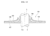
FIGS. 12 and14 , generally, animpeller 101 used for rotary machines, such as a centrifugal compressor, has afixed hub portion 112 of a rotating shaft S, a disc-shaped disc 107 that is provided integrally with thehub portion 112, ashroud 108 that is arranged so as to be spaced apart from thedisc 107 in the axial direction of the central axis L, and a plurality ofblades 106 that are provided in a circumferential direction and connect thedisc 107 to theshroud 108. In this type of impeller, a portion surrounded by the side surfaces of theblades 106 and two mutually facing surfaces of thedisc 107 and theshroud 108 formed aflow passage 103 for compressing air. Additionally, by shrink-fitting thehub portion 112 to the rotating shaft S of the rotary machine, theimpeller 101 is fixed to the rotating shaft S. - The
flow passage 103 opens toward a first end side of the central axis L on the inner peripheral side, curves gradually so as to be directed to a radial outer peripheral side, and opens toward the radial direction on outer peripheral side. That is, theflow passage 103 is formed in a curved shape as viewed from the circumferential direction in order to direct a fluid, which is introduced from the first end side along a second end side, to the radial outer peripheral side (particularly, refer toFIG 14 ). Moreover, as shown inFIG. 13 , as theblades 106 are obliquely connected to thedisc 107, the compression performance of theimpeller 101 is improved, and thereby, theflow passage 103 assumes a complicated three-dimensional shape. - As a method for manufacturing the
impeller 101, a method in which theblades 106 and one of thedisc 107 and theshroud 108 are integrally formed, the other of the disc and shroud is separately manufactured, and these disc and shroud are integrated by welding or brazing, is known. Additionally, since the impeller requires high rigidity, a one-piece impeller with high strength reliability is manufactured by shaving out thedisc 107, theshroud 108, and theblade 106 from a single base material (for example, refer to PTL 1). - [PTL 1] Japanese Patent Application, First Publication No.
2010-285919 - Incidentally, as described above, the
flow passage 103 of theimpeller 101 has a complicated shape having a curved portion, and the inside of the flow passage is narrow. Therefore, during the manufacture of the one-piece impeller 101, it is necessary to perform complicated cutting while inserting, for example, machining members, such as an electrode for machining, from positions to be used as an inlet and an outlet of theflow passage 103. Additionally, in the manufacturing method as described inPTL 1, it is necessary to form the flow passage using a special machining member and substantial manufacturing costs are incurred. - The present invention has been made in consideration of such a situation, and an object thereof is to provide an impeller, a rotary machine including the impeller, and a method for manufacturing the impeller that maintains the performance of the related art while being capable of being manufactured at low cost.
- In order to achieve the above object, an impeller related to a first aspect of the present invention is an impeller including a plurality of blades disposed in a circumferential direction of the impeller, in which each of the blades directs outward from inward in a radial direction of the impeller; a shroud located close to a first end side of an axis of the impeller with respect to the blades, and to which the blades are attached; and a disk located close to a second end side of an axis of the impeller with respect to the blades, to which the blades are attached, and configured to be attached to a rotating shaft. A plurality of flow passages are formed by the blades, the disc, and the shroud. The blades, the shroud and a first portion of the disk close to the second end side of the axis of the impeller are integrated so as to form a first member. A second portion of the disk close to the first end side of the axis of the impeller forms a second member.
- According to the first aspect of the present invention, when a flow passage portion of the first member is formed by splitting the impeller into the first member and the second member and making the second member into a part that constitutes the portion of the disc on the first end side, the accessibility of the machining tool improves. That is, when the machining tool is inserted from a position to be used as the outlet of the flow passage, the machining when forming the flow passage becomes easy by making a part that becomes an interference object, on the inner peripheral side, into a separate second member. Additionally, when the machining tool is inserted from a position to be used as the introduction port that is the inlet of the flow passage, the machining of the introduction port becomes easy by making a part that becomes an interference object into a separate second member. Thereby, the manufacturing time can be shortened, and the manufacturing costs can be kept down.
- In a second aspect of the present invention, in the above impeller, at least one of mutually facing surfaces of the disc and the shroud in the first member is formed into a flat surface.
- According to the second aspect of the present invention, the shape of the flow passage defined by the disc, the shroud, and the blades are further simplified. Therefore, the accessibility of the machining tool can be improved and the man-hours of machining when forming the flow passage can be further reduced.
- In a third aspect of the present invention, in the above impeller, both of the mutually facing surfaces of the disc and the shroud in the first member are formed into flat surfaces.
- According to the third aspect of the present invention, a curved portion is eliminated in a cross-sectional shape when viewed from the circumferential direction in the shape of the flow passage defined by the disc, the shroud, and the blades. Therefore, the man-hours of machining when forming the flow passage can be further reduced.
- In a fourth aspect of the present invention, in the impeller of any one aspect of the second and third aspects, the blades are provided within a range of the flat surface of the disc or the shroud as viewed from the axial direction.
- According to the fourth aspect of the present invention, the shape of the flow passage defined by the disc, the shroud, and the blades are further simplified. Therefore, the accessibility of the machining tool can be improved and the man-hours of machining when forming the flow passage can be further reduced.
- In a fifth aspect of the present invention, in the impeller of any one aspect of the first to four aspects, the surface of the second member that faces the first end side is formed in a curved shape so as to be directed to the radial outer peripheral side as it goes from the first end side to the second end side.
- According to the fifth aspect of the present invention, a fluid introduced into the impeller can be guided to the flow passage without any delay by the surface of the second member that faces the first end side. This can maintain the compression performance of the impeller.
- In a sixth aspect of the present invention, in the impeller of any one aspect of the first to fifth aspects, the first member has a fixed portion that is fixed to the rotating shaft.
- According to the sixth aspect of the present invention, the impeller can be more firmly fixed to the rotating shaft compared to a case where the second member equivalent to a hub portion of a disc of the related art is fixed to the rotating shaft after the first member and the second member are integrated. That is, the impeller can be more firmly fixed to the rotating shaft by directly fixing the first member, which has a weight more than the second member, to the rotating shaft.
- In a seventh aspect of the present invention, in the impeller of any one aspect of the first to sixth aspects, the surface of the blade that forms the flow passage is formed so as to be orthogonal to the surface of the disc that faces the shroud.
- In the seventh aspect of the present invention, the shape of the blade is further simplified as compared to a shape where the surface of the blade that forms the flow passage inclines with respect to the disc. Therefore, the man-hours of machining when forming the flow passage can be further reduced.
- Additionally, an eighth aspect of the present invention provides a rotary machine including the impeller related to any one aspect of the first to seventh aspects.
- By adopting the above impeller, the rotary machine can be provided at low costs.
- Additionally, a method for manufacturing an impeller related to a ninth aspect of the present invention is a method for manufacturing an impeller including a plurality of blades disposed in a circumferential direction of the impeller, in which each of the blades directs outward from inward in a radial direction of the impeller; a shroud located close to a first end side of an axis of the impeller with respect to the blades, and to which the blades are attached; and a disk located close to a second end side of an axis of the impeller with respect to the blades, to which the blades are attached, a plurality of flow passages being formed by the blades, the disc, and the shroud. The method for manufacturing an impeller includes a first member forming step of performing cutting on a base material for forming the second end side of the axis of the impeller to form the flow passages, and forming a first member in which the blades, the shroud, and a first portion of the disc close to the second end side of the impeller are integrally formed; and a second member forming step of forming a second member that constitutes a second portion of the disc close to the first end side of the impeller.
- According to the ninth aspect of the present invention, after the impeller is split into the first member and the second member, these members are formed in separate steps, and the second member formed in the second member forming step is made into a part that constitutes the portion of the disc on the first end side. This improves the accessibility of a machining tool when a flow passage portion of the first member is formed. That is, when the machining tool is inserted from a position to be used as the outlet of the flow passage, the machining when forming the flow passage becomes easy by making a part that becomes an interference object on the inner peripheral side into a separate second member. Additionally, when the machining tool is inserted from a position to be used as the introduction port that is the inlet of the flow passage, the machining of the introduction port becomes easy by making a part that becomes an interference object into a separate second member. Thereby, the manufacturing time can be shortened, and the manufacturing costs can be kept down.
- In a tenth aspect of the present invention, in the above method for manufacturing an impeller, in the second member forming step, the surface of the second member that faces the first end side is formed with a curved portion that is directed to the radial outer peripheral side as it goes from the first end side to the second end side.
- According to the tenth aspect of the present invention, the air introduced into the impeller including the second member formed by the second member forming step can be guided to the flow passage without any delay by the surface of the second member that faces the first end side. Therefore, the performance of the impeller does not degrade.
- According to the present invention, the accessibility of a machining tool improves when a flow passage portion of the impeller is formed. Therefore, the manufacturing time can be shortened and the manufacturing costs can be kept down.
-
-
FIG. 1 is a cross-sectional view showing a centrifugal compressor to which impellers of an embodiment of the present invention is applied. -
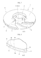
FIG. 2 is a perspective view showing an impeller of the embodiment of the present invention. -
FIG. 3 is an enlarged view of a part A ofFIG. 2 . -
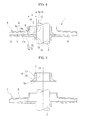
FIG. 4 is a cross-sectional view of the impeller of the embodiment of the present invention. -
FIG. 5 is an exploded cross-sectional view of the impeller of the embodiment of the present invention. -
FIG. 6 is a view showing a manufacturing step of the impeller of the embodiment of the present invention. -
FIG. 7 is a view showing a manufacturing step of the impeller of the embodiment of the present invention. -
FIG. 8 is a view showing a manufacturing step of the impeller of the embodiment of the present invention. -
FIG. 9 is a view showing a manufacturing step of the impeller of the embodiment of the present invention. -
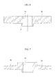
FIG. 10 is a cross-sectional view showing another form of the impeller of the embodiment of the present invention. -
FIG. 11 is a cross-sectional view showing still another form of the impeller of the embodiment of the present invention. -
FIG. 12 is a perspective view showing an impeller of the related art. -
FIG. 13 is an enlarged view of a part B ofFIG. 12 . -
FIG. 14 is a cross-sectional view of the impeller of the related art. - An embodiment of the present invention will be described in detail referring to the drawings.
- A
centrifugal compressor 50 is shown as an example of a rotary machine of the present embodiment inFIG. 1 . Thecentrifugal compressor 50 is mainly constituted by a rotating shaft S that is rotated around an axis P,impellers 1 that are attached to the shaft S and compress a fluid utilizing centrifugal force, and acasing 53 that rotatably supports the rotating shaft S and is formed withflow passages 52 that allow the fluid to flow therethrough from the upstream to the downstream. - The
casing 53 is formed so as to form a substantially columnar outline, and the rotating shaft S is arranged so as to pass through the center of the casing.Journal bearings 54 are provided at both axial ends of the rotating shaft S of thecasing 53, and athrust bearing 55 is provided at one end of the rotating shaft. Thejournal bearings 54 and the thrust bearing 55 rotatably support the rotating shaft S. That is, the rotating shaft S is supported by thecasing 53 via thejournal bearings 54 and thethrust bearing 55. - Additionally, a
suction port 56 into which a fluid is made to flow from the outside is provided on one end side of thecasing 53 in the axial direction, and adischarge port 57 through which the fluid flows out to the outside is provided on the other end side. An internal space, which communicates with thesuction port 56 and thedischarge port 57, respectively, and repeats diameter reduction and diameter increase, is provided within thecasing 53. This internal space functions as a space that accommodates theimpeller 1, and also functions as theabove flow passages 52. That is, thesuction port 56 and thedischarge port 57 communicate with each other via theimpellers 1 and theflow passages 52. - A plurality of
impellers 1 is arranged at intervals in the axial direction of the rotating shaft S. In addition, although siximpellers 1 are provided in the illustrated example, at least one or more impellers may be provided. - As shown in
FIGS. 2 and4 , theimpeller 1 has a substantially disc shape, and is configured so that a fluid suctioned from anintroduction port 2 that opens to a first side in the direction (hereinafter referred to as an axial direction) of a central axis L is discharged toward the radial outer peripheral side viaflow passages 3 formed inside theimpeller 1. - In addition, in the following, the outer peripheral side of the
impeller 1 in the radial direction is simply referred to as outer peripheral side. Additionally, the inner peripheral side of theimpeller 1 in the radial direction is simply referred to as inner peripheral side. Additionally, the upper side ofFIGS. 2 and4 that becomes the upstream side of the fluid is referred to as a first end side, and the lower side ofFIGS. 2 and4 that becomes the downstream side of the fluid is referred to as a second end side. - The
impeller 1 of the present embodiment is equipped with a substantially disc-shapedfirst member 4 that forms the second end side, and a substantially cylindricalsecond member 5 that forms the first end side and that has an outer peripheral surface that is gradually increased in diameter toward the second end side. Adisc 7 that is fixed to the rotating shaft S in theimpeller 1, a plurality ofblades 6 that are provided in the circumferential direction on the first end side of thedisc 7 so as to be directed from the inner peripheral side to the outer peripheral side, and ashroud 8 that is provided to face thedisc 7 on the first end side and is attached to theblades 6 are constituted by thefirst member 4 and thesecond member 5. Thefirst member 4 and thesecond member 5 are not fixed to each other in the present embodiment but are fixed to the rotating shaft S, respectively, whereby theintroduction port 2 is defined between thefirst member 4 and thesecond member 5, and thefirst member 4 and thesecond member 5 further defines a suction portion 9 that connects theintroduction port 2 and theflow passages 3. - The
first member 4 is arranged from the radial inner peripheral side toward the radial outer peripheral side. Thefirst member 4 is equipped with a plurality ofblades 6 disposed in a circumferential direction of the impeller, afirst portion 7a that is provided on the second end side of theblades 6 and constitutes the second end side of thedisc 7 to which theblades 6 are attached, and theshroud 8 that is provided on the first end side of theblades 6 and has theblades 6 attached thereto. That is, theshroud 8 is arranged so as to be spaced apart from thefirst portion 7a of thedisc 7 by a predetermined distance. Thefirst member 4 is formed from, for example, precipitation-hardened stainless steel. - The
first portion 7a of thedisc 7 includes a fixedportion 12 that is fixed to the rotating shaft S, and adisc body portion 11 that is formed integrally with the fixedportion 12 and has a substantially disc shape. - The fixed
portion 12 is formed in a cylindrical shape that has afitting hole 13, which penetrates in the axial direction, at a central portion thereof. Thefitting hole 13 is a hole that is inserted and fitted to the rotating shaft S when theimpeller 1 is fixed to the rotating shaft S. Thedisc body portion 11 has a substantially circular shape as viewed from the axial direction and is formed at one axial end of the fixedportion 12. Additionally, onesurface 11a of thedisc body portion 11 on the first end side is formed into a substantially flat surface. - In other words, the fixed
portion 12 is a columnar part that protrudes to the second end side in the central portion of thedisc body portion 11. The fixedportion 12 protrudes to the second end side by a predetermined amount. This protruding amount is appropriately set according to a fastening force required in order to shrink-fit and fix theimpeller 1 to the rotating shaft S. - The plurality of
blades 6 are provided in the onesurface 11a of thedisc body portion 11. The plurality ofblades 6 have a constant plate thickness (blade thickness), respectively, and are provided at regular intervals in the circumferential direction in a substantially radial shape from the radial inner peripheral side toward the radial outer peripheral side. Additionally, theblades 6 extend so as to curve toward one direction in the circumferential direction as they go from the radial inner peripheral side of thedisc 7 to the radial outer peripheral side, respectively. - Additionally, an
inner end portion 6a of theblade 6 on the radial inner peripheral side is spaced apart from an inner peripheral surface 13a of thefitting hole 13 by a predetermined distance G This distance G is appropriately set according to the shapes or the like of the suction portion 9 and theflow passages 3 that communicate with the suction portion 9, and is set so as to be located closer to the outer peripheral side than an outer peripheral end of thesecond member 5. - The
shroud 8 is a substantially disc-shaped member that is provided integrally with theblades 6 so as to cover the plurality ofblades 6 from the first end side. Theshroud 8 is formed in the shape of a disc centered on the central axis L. Specifically, theshroud 8 is formed in the shape of an umbrella that is gradually reduced in diameter as it goes to the first end side. Additionally, the radial inner peripheral side of theshroud 8 constitutes acylindrical portion 14 that rises to the first end side. Thecylindrical portion 14 defines theintroduction port 2 together with a smaller-diameter surface 17 (refer toFIG. 5 ) of thesecond member 5 by combining thefirst member 4 and thesecond member 5. - Additionally, a range where the
blades 6 are formed, in theother surface 8a of theshroud 8 on the second end side, that is, the surface of theshroud 8 that faces the onesurface 11a of thedisc 7, is formed into a substantially flat surface. - That is, as for the
other surface 8a of theshroud 8, a cross-section perpendicular to the axial direction in the range where theblades 6 are formed can be drawn in a straight line. - As shown in
FIG. 3 , theflow passage 3 is formed between theblades 6, thefirst portion 7a of thedisc 7, and theshroud 8. In other words, theflow passage 3 is configured by a space surrounded by the onesurface 11a of thedisc 7, theother surface 8a that is the surface of theshroud 8 on the second end side, and asurface 6b of oneblade 6 on the other circumferential side, and asurface 6c of theother blade 6 on one circumferential side, in theblades 6 that are adjacent to each other. - Additionally, in the present embodiment, the
blade 6 is provided so as to become substantially perpendicular to the onesurface 11a of thedisc 7. In other words, the cross-sectional shape of theflow passage 3 defined by theblades 6, thedisc 7, and theshroud 8 becomes rectangular. That is, the surfaces of theblades 6 that form theflow passage 3 are formed so as to be substantially orthogonal to the onesurface 11a of thedisc 7. - The
second member 5 has the second portion 7b of thedisc 7, and is a substantially cylindrical member centered on the central axis L. Thesecond member 5 has the outerperipheral surface 16 that is gradually increased in diameter toward the second end side. A radial central portion of thesecond member 5 is formed with a secondfitting hole 15 that has almost the same internal diameter as thefitting hole 13. Additionally, theother end surface 5a of thesecond member 5 is formed into a flat surface. - The outer
peripheral surface 16 of thesecond member 5 includes the smaller-diameter surface 17 and an increaseddiameter surface 18. The smaller-diameter surface 17 including an end portion of thesecond member 5 on the first end side is formed so as to have the same diameter along the axial direction. - The increased
diameter surface 18 including an end portion of thesecond member 5 on the second end side is formed into a curved surface that is gradually increased in diameter toward theother end surface 5a. The smaller-diameter surface 17 and the increaseddiameter surface 18 are gently connected. Additionally, the increaseddiameter surface 18 is formed so that the normal line of the increaseddiameter surface 18 substantially faces the axial direction on the other end portion. - That is, when the
first member 4 and thesecond member 5 are combined, these members are formed so that the increaseddiameter surface 18 and the onesurface 11 a of thedisc 7 are gently connected. - Additionally, the diameter of the
other end surface 5a of thesecond member 5 is formed so as to become smaller than the internal diameter of thecylindrical portion 14 of theshroud 8. - In addition, the shape of the increased
diameter surface 18 may be an oblique surface with a constant angle, without being limited to the curved surface as described above. Additionally, and in particular the smaller-diameter surface 17 does not need to be provided, and the outerperipheral surface 16 may be constituted only by the increaseddiameter surface 18. - Next, a method for assembling the
impeller 1 of the present embodiment to the rotating shaft S will be described. First, as shown inFIG. 5 , the inner peripheral surface of the fixedportion 12 of thefirst member 4 is fixed to the rotating shaft S by shrink-fitting. Specifically, the inner peripheral surface of thefitting hole 13 of thefirst member 4 is heated whereby thefitting hole 13 is increased in diameter, and in this state, thefitting hole 13 is inserted through the rotating shaft S. Then, thefirst member 4 and the rotating shaft S are integrally anchored by cooling the periphery of thefitting hole 13 to reduce the diameter thereof, and bringing thefitting hole 13 into contact with the outer peripheral surface of the rotating shaft S. - Next, similarly to the
first member 4, thesecond member 5 is fixed to the rotating shaft S by shrink-fitting. In this case, the shrink-fitting is performed after theother end surface 5a of thesecond member 5 is made to abut against the onesurface 11a of thedisc 7 of the first member. - In addition, the order of being fixed to the rotating shaft S is not limited to the above-described order, and the
first member 4 may be fixed to the rotating shaft S after thesecond member 5 is fixed to the rotating shaft S. - As described above, the
impeller 1 is formed by thefirst member 4 and thesecond member 5 that are assembled to the rotating shaft S. As theother end surface 5a of thesecond member 5 and the onesurface 11a of thefirst member 4 abut against each other, the relative positions of thefirst member 4 and thesecond member 5 are determined, and thereby, theintroduction port 2 and the suction portion 9 are defined. - In addition, the assembling method is not limited to the above-described method, for example, a method for fixing the
first member 4 and thesecond member 5 to the rotating shaft S after thesecond member 5 is joined to thefirst member 4 by methods, such as welding, may be used. - In the
impeller 1 shown above, a fluid that has flowed in from theintroduction port 2 is directed to the outer peripheral side from the inner peripheral side by the increaseddiameter surface 18 of thesecond member 5 in the suction portion 9. Next, the fluid that has flowed into theflow passages 3 from the suction portion 9 is accelerated by a centrifugal force generated by the rotation of the rotating shaft S by a driving source that is not shown, and is discharged from the outer peripheral ends of theflow passages 3. - A method for manufacturing the above-described
impeller 1 of the present embodiment will be described. The method for manufacturing theimpeller 1 related to the present embodiment has a first member forming step of forming thefirst member 4, and a second member forming step of forming thesecond member 5. - The first member forming step has a first base material forming step and a cutting step. First, as shown in
FIG. 6 , as the first base material forming step, a substantiallycylindrical base material 30, which is formed with thefitting hole 13 through which the rotating shaft S is inserted and the fixedportion 12, is forged. Then, as shown inFIG. 7 , aninclined surface 8b that is the surface of theshroud 8 on the first end side is formed by, for example, lathing or the like to form adisc body 32. - In addition, here, although the
base material 30 is subjected to lathing or the like so as to form thedisc body 32, thedisc body 32 may be formed only by forging. Additionally, here, although thecylindrical base material 30 which is formed with thefitting hole 13 and the fixedportion 12 by forging, is adopted, thefitting hole 13 and the fixedportion 12 are subjected to lathing or the like, for example, using a disc-shaped base material. - Next, as shown in
FIG. 8 , as the cutting step, theflow passage 3 is formed from the outer peripheral side of thedisc body 32. Specifically, theflow passage 3 is formed by inserting anelectrode 33 corresponding to the shape of theflow passage 3 from a position to be used as an outlet of theflow passage 3, by a spark erosion method. - Here, the
electrode 33 is a rectangular elongated member as viewed from the cross-section thereof. Additionally, theelectrode 33 has a shape having a height smaller than the height of theflow passage 3, and has a curved shape and a width dimension corresponding to a shape viewed from the axial direction of theflow passage 3. Additionally, theelectrode 33 is formed from, for example, graphite, copper, or the like, and is attached to an electrical discharge machine that is not shown. - As for spark erosion, first, the
disc body 32 is dipped in, for example, spark erosion oil that is not shown. Next, as shown inFIG. 8 , thedisc body 32 and theflow passage 3 are relatively moved in the radial direction and the circumferential direction, respectively, while a portion that becomes theflow passage 3 are inserted using theelectrode 33. Additionally, the disc body is also moved in the axial direction if necessary, and spark erosion is performed. In addition, in this case, the machining conditions (a current, a voltage, a pulse, and a feed rate) of the spark erosion by theelectrode 33 may be appropriately changed. - A plurality of the
flow passages 3 are formed by repeatedly carrying out the steps shown above, regarding eachflow passage 3 to be formed in theimpeller 1. - Next, as shown in
FIG. 9 , theelectrode 33 is inserted from the first end side, and the inner peripheral surface of theshroud 8 is machined. - In addition, in the present embodiment, spark erosion is performed by one type of
electrode 33. However, the electrode is not limited to this. For example, roughing, intermediate machining, and finishing may be performed using two or more types of electrodes with different sizes or materials. - Next, in the second member forming step, the second member 5 (refer to
FIG. 5 ) is formed by performing lathing of the cylindrical base material. In the second member forming step, the outerperipheral surface 16 that has the curved increaseddiameter surface 18 that goes to the radial outer peripheral side is formed as it goes from the second direction to the first direction in the axial direction in thesecond member 5. - In addition, not only the
second member 5 may be obtained by performing lathing of the base material but thesecond member 5 may be formed only by forging. - According to the above embodiment, the shape of the
flow passage 3 formed by theblades 6, thedisc 7, and theshroud 8 of thefirst member 4 forms a substantially straight shape as viewed from the circumferential direction. Therefore, the spark erosion using thestraight electrode 33 becomes easier. Since thesecond member 5 equivalent to a hub portion of related art for directing the air introduced in the axial direction to the radial direction is a separate member, machining of theintroduction port 2 in the vicinity of theimpeller 1 becomes easier. - In other words, when the
flow passage 3 of thefirst member 4 is formed by splitting theimpeller 1 into thefirst member 4 and thesecond member 5 and making thesecond member 5 into a part that constitutes the portion of thedisc 7 on the first end side, the accessibility of theelectrode 33 improves. That is, when theelectrode 33 is inserted from a position to be used as the outlet of theflow passage 3, the machining when forming theflow passage 3 becomes easy by making a part that becomes an interference object on the inner peripheral side into a separatesecond member 5. Additionally, when theelectrode 33 is inserted from a position to be used as theintroduction port 2 that is the inlet of theflow passage 3, the machining of theintroduction port 2 becomes easy by making a part that becomes an interference object on the second end side into a separatesecond member 5. Thereby, the manufacturing time can be shortened, and the manufacturing costs can be kept down. - Additionally, since the fluid introduced into the
impeller 1 can be guided to theflow passage 3 without any delay by the increaseddiameter surface 18 in thesecond member 5, the compression performance of theimpeller 1 can be maintained. - Additionally, since the
first member 4 and thesecond member 5 are separately shrink-fitted and fixed to the rotating shaft S, respectively, theimpeller 1 can be more firmly fixed to the rotating shaft S as compared to a case where any member is fixed to the rotating shaft S after thefirst member 4 and thesecond member 5 are integrated. - Additionally, the surface of the
blades 6 that forms theflow passage 3 are formed so as to be orthogonal to thedisc 7 whereby the shape of theblades 6 are further simplified as compared to a shape where the surfaces of theblades 6 that form theflow passage 3 inclines with respect to thedisc 7. Therefore, the man-hours of machining when theflow passage 3 is formed can be further reduced. - In addition, the technical scope of the present invention is not limited to the above embodiment, and various changes can be made without departing from the scope of the present invention.
- In the above embodiment, the
other end surface 5a of thesecond member 5 and the onesurface 11a of thefirst member 4 are made into substantially flat surfaces, respectively. In contrast, as shown inFIG. 10 , a configuration in which the other end surface 5Ba of asecond member 5B that constitutes animpeller 1B is provided with aconvex portion 20 of a shape that extends the other end surface 5Ba to the second end side, and aconcave portion 21 corresponding to theconvex portion 20 is provided in one surface 11Ba of afirst member 4B may be adopted. - Here, although the
second member 5B and thefirst member 4B are fixed by shrink-fitting or the like in the other end surface 5Ba of thesecond member 5B, it is not necessary to fix thesecond member 5B and the rotating shaft S. - Since the outer peripheral side of the other end surface 5Ba of the
second member 5B does not have a thin-walled shape in such a configuration, machining of thesecond member 5B becomes easy. - Additionally, as shown in
FIG. 11 , thefirst member 4C that constitutes the impeller 1C is not necessarily provided with a fixed portion that extends to the second side of the disc 7C. In the case of this form, it is preferable that the dimension d from the end portion of thesecond member 5C on the second end side be as great as possible within a range where the fixation strength between thefirst member 4C and the rotating shaft S can be sufficiently secured. As the dimension d is enlarged, the accessibility of a machining member during machining of theflow passage 3C and the introduction port 2C is increased, which is preferable. - Moreover, in
FIG 10 , the fixed portion is not necessarily provided even in a case where thesecond member 5B is, for example, shrink-fitted to the rotating shaft S and thefirst member 4B. - Additionally, the method for machining the flow passage or the like may not be limited to the spark erosion, and a flow passage or the like may be worked by machining.
- According to the impeller of the present invention, the accessibility of a machining tool improves when a flow passage portion of the impeller is formed. Therefore, manufacturing time can be shortened. Additionally, in the impeller of the present invention, manufacturing costs can be kept down.
-
- S: ROTATING SHAFT
- 1: IMPELLER
- 3: FLOW PASSAGE
- 4: FIRST MEMBER
- 5: SECOND MEMBER
- 6: BLADE
- 7: DISC
- 8: SHROUD
- 8A: OTHER SURFACE
- 11: DISC BODY PORTION
- 11A: ONE SURFACE
- 12: FIXED PORTION
- 18: INCREASED DIAMETER SURFACE
- 50: CENTRIFUGAL COMPRESSOR (ROTARY MACHINE)
Claims (10)
- An impeller comprising:a plurality of blades disposed in a circumferential direction of the impeller, in which each of the blades directs outward from inward in a radial direction of the impeller;a shroud located close to a first end side of an axis of the impeller with respect to the blades, and to which the blades are attached; anda disk located close to a second end side of an axis of the impeller with respect to the blades, to which the blades are attached, and configured to be attached to a rotating shaft; whereina plurality of flow passages are formed by the blades, the disk and the shroud,the blades, the shroud and a first portion of the disk close to the second end side of the axis of the impeller are integrated so as to form a first member, anda second portion of the disk close to the first end side of the axis of the impeller forms a second member.
- The impeller according to Claim 1,
wherein at least one of the mutually facing surfaces of the disc and the shroud in the first member is formed into a flat surface. - The impeller according to Claim 2,
wherein both of the mutually facing surfaces of the disc and the shroud in the first member are formed into flat surfaces. - The impeller according to Claim 2,
wherein the blades are provided within a range of the flat surface of the disc or the shroud as viewed from the axial direction. - The impeller according to Claim 1,
wherein the surface of the second member that faces the first end side is formed in a curved shape so as to be directed to the radial outer peripheral side as it goes from the first end side to the second end side. - The impeller according to Claim 1,
wherein the first member has a fixed portion that is fixed to the rotating shaft. - The impeller according to Claim 1,
wherein the surface of the blade that forms the flow passage is formed so as to be orthogonal to the surface of the disc that faces the shroud. - A rotary machine comprising the impeller according to any one of Claims 1 to 7.
- A method for manufacturing an impeller including a plurality of blades disposed in a circumferential direction of the impeller, in which each of the blades directs outward from inward in a radial direction of the impeller; a shroud located close to a first end side of an axis of the impeller with respect to the blades, and to which the blades are attached; and a disk located close to a second end side of an axis of the impeller with respect to the blades, to which the blades are attached, a plurality of flow passages being formed by the blades, the disc, and the shroud, the method comprising:a first member forming step of performing cutting on a base material for forming the second end side of the axis of the impeller to form the flow passages, and forming a first member in which the blades, the shroud, and a first portion of the disc close to the second end side of the axis of the impeller are integrally formed; anda second member forming step of forming a second member that constitutes a second portion of the disc close to the first end side of the axis of the impeller.
- The method for manufacturing an impeller according to Claim 9,
wherein, in the second member forming step, the surface of the second member that faces the first end side is formed with a curved portion that is directed to the radial outer peripheral side as it goes from the first end side to the second end side.
Applications Claiming Priority (2)
| Application Number | Priority Date | Filing Date | Title |
|---|---|---|---|
| JP2011185838A JP2013047479A (en) | 2011-08-29 | 2011-08-29 | Impeller and rotary machine with the same, and method for manufacturing impeller |
| PCT/JP2011/078790 WO2013031038A1 (en) | 2011-08-29 | 2011-12-13 | Impeller, rotary machine with impeller, and method for manufacturing impeller |
Publications (2)
| Publication Number | Publication Date |
|---|---|
| EP2752582A1 true EP2752582A1 (en) | 2014-07-09 |
| EP2752582A4 EP2752582A4 (en) | 2015-08-26 |
Family
ID=47755576
Family Applications (1)
| Application Number | Title | Priority Date | Filing Date |
|---|---|---|---|
| EP11869760.6A Withdrawn EP2752582A4 (en) | 2011-08-29 | 2011-12-13 | Impeller, rotary machine with impeller, and method for manufacturing impeller |
Country Status (5)
| Country | Link |
|---|---|
| US (1) | US9903385B2 (en) |
| EP (1) | EP2752582A4 (en) |
| JP (1) | JP2013047479A (en) |
| CN (1) | CN103097739B (en) |
| WO (1) | WO2013031038A1 (en) |
Cited By (1)
| Publication number | Priority date | Publication date | Assignee | Title |
|---|---|---|---|---|
| EP3251787B1 (en) | 2016-05-31 | 2024-08-14 | Sulzer Management AG | Method for producing a component of a rotary machine and component produced according to such a method |
Families Citing this family (16)
| Publication number | Priority date | Publication date | Assignee | Title |
|---|---|---|---|---|
| EP2669042A1 (en) * | 2012-05-30 | 2013-12-04 | Sulzer Markets and Technology AG | Method for producing a workpiece using a cutting device |
| JP6327505B2 (en) * | 2013-11-21 | 2018-05-23 | 三菱重工業株式会社 | Impeller and rotating machine |
| JP6064179B2 (en) * | 2014-06-11 | 2017-01-25 | パナソニックIpマネジメント株式会社 | Temperature conditioning unit, temperature conditioning system, and vehicle equipped with temperature conditioning unit |
| JP6678302B2 (en) * | 2015-07-24 | 2020-04-08 | パナソニックIpマネジメント株式会社 | Temperature control unit, temperature control system, vehicle |
| JP2017155641A (en) * | 2016-03-01 | 2017-09-07 | 三菱重工コンプレッサ株式会社 | Rotary machine and process of manufacture of rotary machine |
| US11065715B2 (en) * | 2016-05-03 | 2021-07-20 | General Electric Company | Combined liquid guided laser and electrical discharge machining |
| EP3421809B1 (en) * | 2016-09-05 | 2020-05-27 | Mitsubishi Heavy Industries Compressor Corporation | Method for manufacturing centrifugal rotary machine and method for manufacturing impeller therefor |
| EP3557076B1 (en) | 2017-02-20 | 2021-01-13 | Mitsubishi Heavy Industries Compressor Corporation | Impeller, rotary machine, method for manufacturing impeller, and method for manufacturing rotary machine |
| JP7016507B2 (en) * | 2017-04-21 | 2022-02-07 | 株式会社不二製作所 | An impeller for accelerating abrasives in a blasting device, a blasting device, and a method for manufacturing the impeller. |
| ES3047702T3 (en) * | 2017-08-24 | 2025-12-04 | Ge Renewable Switzerland Gmbh | Hydroelectric machine with bi-directional radial fan |
| US20190265150A1 (en) * | 2018-02-23 | 2019-08-29 | Baker Hughes, A Ge Company, Llc | Slotted discs representative of formation fractures |
| DE102018108762A1 (en) * | 2018-04-12 | 2019-10-17 | Gühring KG | Suction device with blades as well as the production process intended for this purpose |
| JP7149174B2 (en) * | 2018-12-10 | 2022-10-06 | ダイキン工業株式会社 | Closed impeller and manufacturing method thereof |
| JP7161424B2 (en) * | 2019-02-26 | 2022-10-26 | 三菱重工コンプレッサ株式会社 | impeller and rotating machinery |
| CN112192150B (en) * | 2020-09-21 | 2022-11-04 | 贵州新安航空机械有限责任公司 | Open impeller machining process |
| WO2022187038A1 (en) * | 2021-03-05 | 2022-09-09 | Danfoss A/S | Techniques for applying brazing material to form a shrouded impeller |
Family Cites Families (47)
| Publication number | Priority date | Publication date | Assignee | Title |
|---|---|---|---|---|
| DE755198C (en) | 1935-12-20 | 1952-11-24 | Versuchsanstalt Fuer Luftfahrt | Centrifugal machine impeller for high peripheral speeds |
| US2613609A (en) | 1942-01-28 | 1952-10-14 | Buchi Alfred | Compressing machine such as centrifugal blower or pump |
| US2438866A (en) | 1945-06-01 | 1948-03-30 | United Aircraft Corp | Impeller mounting |
| US2799445A (en) | 1955-12-12 | 1957-07-16 | Gen Electric | High speed rotor |
| FR1471604A (en) | 1966-03-10 | 1967-03-03 | Neu Sa | Improvement in the construction of closed wheels of centrifugal compressors in light alloy |
| DE2621201C3 (en) | 1976-05-13 | 1979-09-27 | Maschinenfabrik Augsburg-Nuernberg Ag, 8900 Augsburg | Impeller for a turbomachine |
| US4231706A (en) | 1977-04-27 | 1980-11-04 | Hitachi, Ltd. | Impeller of a centrifugal blower |
| US4173429A (en) | 1977-12-05 | 1979-11-06 | Westinghouse Electric Corp. | Centrifugal fan, shaft, plate and hub assembly |
| CA1131247A (en) | 1978-06-12 | 1982-09-07 | Burton Brooks | Sulfonation of alkylated aromatic hydrocarbons |
| JPS555456A (en) * | 1978-06-28 | 1980-01-16 | Hitachi Ltd | No-hub pump |
| US4220372A (en) | 1978-11-06 | 1980-09-02 | Allis-Chalmers Corporation | Dual wheel and axle assembly |
| JPS5872491A (en) | 1981-10-28 | 1983-04-30 | Hitachi Ltd | Printing pressure regulating mechanism |
| US4602411A (en) | 1984-01-13 | 1986-07-29 | Westinghouse Electric Corp. | Method for fabricating a rotor disc assembly |
| JPS61142393A (en) | 1984-12-17 | 1986-06-30 | Mitsubishi Heavy Ind Ltd | Wear resistant impeller |
| JPS61212601A (en) | 1985-03-18 | 1986-09-20 | Mitsubishi Heavy Ind Ltd | Vane wheel installation structure for rotary machine |
| JPH0417762Y2 (en) | 1985-06-19 | 1992-04-21 | ||
| SU1373883A1 (en) | 1986-01-17 | 1988-02-15 | Производственное объединение "Невский завод" им.В.И.Ленина | Centrifugal compressor impeller |
| DE3709518C2 (en) | 1987-03-23 | 1995-01-19 | Hilge Philipp Gmbh | Wheel |
| ES2048868T3 (en) | 1989-01-19 | 1994-04-01 | Ebara Corp | PUMP ROTOR. |
| CN2069501U (en) | 1990-04-29 | 1991-01-16 | 重庆钢都机修厂 | Vane wheel for big centrifugal blower |
| JP2730268B2 (en) | 1990-05-25 | 1998-03-25 | ダイキン工業株式会社 | Centrifugal impeller |
| JP2788818B2 (en) | 1992-03-31 | 1998-08-20 | シャープ株式会社 | Active matrix input / output device |
| DE4427115C1 (en) | 1994-07-30 | 1995-04-06 | Braun Ag | Impeller for a radial-flow fan |
| CN1160516C (en) * | 1998-05-13 | 2004-08-04 | 松下电器产业株式会社 | Electric blower and electric vacuum cleaner using it |
| JP2001355595A (en) * | 2000-06-13 | 2001-12-26 | Hitachi Ltd | Method for manufacturing pump impeller and pump using the impeller |
| US6481970B2 (en) | 2000-06-28 | 2002-11-19 | Honeywell International Inc. | Compressor wheel with prestressed hub and interference fit insert |
| IT1319495B1 (en) | 2000-11-30 | 2003-10-20 | Nuovo Pignone Spa | PROCEDURE FOR THE CONSTRUCTION OF A ROTOR FOR COMPRESSOR-CENTRIFUGHI. |
| JP2003293988A (en) | 2002-04-01 | 2003-10-15 | Mitsubishi Heavy Ind Ltd | Multi-stage rotor and centrifugal compressor with the rotor |
| JP2004036444A (en) | 2002-07-02 | 2004-02-05 | Ishikawajima Harima Heavy Ind Co Ltd | Method for manufacturing impeller with shroud |
| JP2004060460A (en) | 2002-07-25 | 2004-02-26 | Mitsubishi Heavy Ind Ltd | Impeller for compressor, and method of mounting impeller |
| ITMI20021876A1 (en) | 2002-09-03 | 2004-03-04 | Nuovo Pignone Spa | IMPROVED PROCEDURE FOR MAKING A ROTOR OF ONE |
| JP4428044B2 (en) * | 2003-03-24 | 2010-03-10 | 株式会社日立プラントテクノロジー | Impeller manufacturing method and impeller |
| CN2763589Y (en) | 2004-12-14 | 2006-03-08 | 上海连成(集团)有限公司 | Rotor for high-temperature high-pressure pump |
| US7341430B2 (en) | 2004-12-28 | 2008-03-11 | Nissan Motor Co., Ltd. | Vane wheel for torque converter and manufacturing method |
| US7632073B2 (en) | 2005-06-08 | 2009-12-15 | Dresser-Rand Company | Impeller with machining access panel |
| JP4935435B2 (en) | 2007-03-09 | 2012-05-23 | トヨタ自動車株式会社 | Shrink fit fastening structure of gas turbine |
| JP2009156122A (en) | 2007-12-26 | 2009-07-16 | Mitsubishi Heavy Ind Ltd | Impeller for centrifugal compressor |
| CN101255871A (en) * | 2008-01-22 | 2008-09-03 | 上海东方泵业(集团)有限公司 | Method for processing water pump impeller |
| ATE522726T1 (en) * | 2008-07-10 | 2011-09-15 | Grundfos Management As | FLOW-CONTRACTING COMPONENT OF A PUMP |
| JP2010121612A (en) * | 2008-10-23 | 2010-06-03 | Mitsubishi Heavy Ind Ltd | Impeller, compressor, and method of manufacturing the impeller |
| JP4699531B2 (en) * | 2009-01-27 | 2011-06-15 | 三菱重工業株式会社 | Impeller manufacturing method and impeller |
| JP5107306B2 (en) | 2009-06-10 | 2012-12-26 | 三菱重工業株式会社 | Manufacturing method of impeller of centrifugal rotating machine and impeller of centrifugal rotating machine |
| DE102009031737A1 (en) | 2009-07-04 | 2011-07-21 | MAN Diesel & Turbo SE, 86153 | Impeller for a turbomachine |
| JP5606358B2 (en) | 2011-02-24 | 2014-10-15 | 三菱重工業株式会社 | Impeller, rotor provided with the same, and method for manufacturing impeller |
| JP5907723B2 (en) | 2011-12-26 | 2016-04-26 | 三菱重工業株式会社 | Manufacturing method of rotating machine |
| JP5777529B2 (en) | 2012-01-05 | 2015-09-09 | 三菱重工業株式会社 | Impeller, rotor provided with the same, and method for manufacturing impeller |
| CN205117803U (en) | 2015-11-20 | 2016-03-30 | 湖北双剑鼓风机股份有限公司 | Monopole coal gas centrifugal blower prevents leaking wheel hub |
-
2011
- 2011-08-29 JP JP2011185838A patent/JP2013047479A/en not_active Withdrawn
- 2011-12-13 EP EP11869760.6A patent/EP2752582A4/en not_active Withdrawn
- 2011-12-13 US US13/812,617 patent/US9903385B2/en active Active
- 2011-12-13 WO PCT/JP2011/078790 patent/WO2013031038A1/en not_active Ceased
- 2011-12-13 CN CN201180036597.XA patent/CN103097739B/en not_active Expired - Fee Related
Cited By (1)
| Publication number | Priority date | Publication date | Assignee | Title |
|---|---|---|---|---|
| EP3251787B1 (en) | 2016-05-31 | 2024-08-14 | Sulzer Management AG | Method for producing a component of a rotary machine and component produced according to such a method |
Also Published As
| Publication number | Publication date |
|---|---|
| JP2013047479A (en) | 2013-03-07 |
| EP2752582A4 (en) | 2015-08-26 |
| US20140050585A1 (en) | 2014-02-20 |
| US9903385B2 (en) | 2018-02-27 |
| WO2013031038A1 (en) | 2013-03-07 |
| CN103097739A (en) | 2013-05-08 |
| CN103097739B (en) | 2016-11-02 |
Similar Documents
| Publication | Publication Date | Title |
|---|---|---|
| US9903385B2 (en) | Impeller, rotary machine including the same, and method for manufacturing impeller | |
| US20170107821A1 (en) | Turbine wheel for a radial turbine | |
| JP5118649B2 (en) | Impeller | |
| US9664055B2 (en) | Impeller and rotary machine provided with the same | |
| US9611742B2 (en) | Impeller, rotor comprising same, and impeller manufacturing method | |
| KR20150120412A (en) | Method for making an impeller from sector segments | |
| US11286927B2 (en) | Pump device | |
| US10443605B2 (en) | Impeller, rotary machine, and impeller manufacturing method | |
| US20150093267A1 (en) | Centrifugal Impeller and Centrifugal Blower | |
| US10994347B2 (en) | Method for manufacturing centrifugal rotary machine and method for manufacturing impeller thereof | |
| JP2013139753A (en) | Impeller, rotor comprising the same, and impeller manufacturing method | |
| US20110064562A1 (en) | Turbomolecular Pump | |
| US10982548B2 (en) | Impeller, rotary machine, method for manufacturing impeller, and method for manufacturing rotary machine | |
| US20190040874A1 (en) | Centrifugal Impeller and Centrifugal Blower | |
| US11278999B2 (en) | Manufacturing method of impeller | |
| EP3686437B1 (en) | Impeller and rotary machine | |
| JP4898325B2 (en) | Motor and electric fuel pump using the motor | |
| JP2010196680A (en) | Double suction pump | |
| US11454236B2 (en) | Method for manufacturing compressor casing, casing blank, and compressor casing | |
| EP3425160B1 (en) | Rotor with sliding vane | |
| JPH1181914A (en) | Assembly integrated vane and manufacture thereof | |
| JP2018025198A (en) | Axial flow pump |
Legal Events
| Date | Code | Title | Description |
|---|---|---|---|
| PUAI | Public reference made under article 153(3) epc to a published international application that has entered the european phase |
Free format text: ORIGINAL CODE: 0009012 |
|
| 17P | Request for examination filed |
Effective date: 20130129 |
|
| AK | Designated contracting states |
Kind code of ref document: A1 Designated state(s): AL AT BE BG CH CY CZ DE DK EE ES FI FR GB GR HR HU IE IS IT LI LT LU LV MC MK MT NL NO PL PT RO RS SE SI SK SM TR |
|
| DAX | Request for extension of the european patent (deleted) | ||
| RA4 | Supplementary search report drawn up and despatched (corrected) |
Effective date: 20150724 |
|
| RIC1 | Information provided on ipc code assigned before grant |
Ipc: F04D 29/22 20060101AFI20150720BHEP Ipc: F04D 29/28 20060101ALI20150720BHEP |
|
| 17Q | First examination report despatched |
Effective date: 20160713 |
|
| RAP1 | Party data changed (applicant data changed or rights of an application transferred) |
Owner name: MITSUBISHI HEAVY INDUSTRIES COMPRESSOR CORPORATION |
|
| GRAP | Despatch of communication of intention to grant a patent |
Free format text: ORIGINAL CODE: EPIDOSNIGR1 |
|
| INTG | Intention to grant announced |
Effective date: 20180711 |
|
| STAA | Information on the status of an ep patent application or granted ep patent |
Free format text: STATUS: THE APPLICATION IS DEEMED TO BE WITHDRAWN |
|
| 18D | Application deemed to be withdrawn |
Effective date: 20181122 |