EP2752376A1 - Automated warehouse system - Google Patents
Automated warehouse system Download PDFInfo
- Publication number
- EP2752376A1 EP2752376A1 EP20120827204 EP12827204A EP2752376A1 EP 2752376 A1 EP2752376 A1 EP 2752376A1 EP 20120827204 EP20120827204 EP 20120827204 EP 12827204 A EP12827204 A EP 12827204A EP 2752376 A1 EP2752376 A1 EP 2752376A1
- Authority
- EP
- European Patent Office
- Prior art keywords
- movable platform
- storage
- disposed
- automated warehouse
- warehouse system
- Prior art date
- Legal status (The legal status is an assumption and is not a legal conclusion. Google has not performed a legal analysis and makes no representation as to the accuracy of the status listed.)
- Granted
Links
Images





Classifications
-
- B—PERFORMING OPERATIONS; TRANSPORTING
- B65—CONVEYING; PACKING; STORING; HANDLING THIN OR FILAMENTARY MATERIAL
- B65G—TRANSPORT OR STORAGE DEVICES, e.g. CONVEYORS FOR LOADING OR TIPPING, SHOP CONVEYOR SYSTEMS OR PNEUMATIC TUBE CONVEYORS
- B65G1/00—Storing articles, individually or in orderly arrangement, in warehouses or magazines
- B65G1/02—Storage devices
- B65G1/04—Storage devices mechanical
- B65G1/0492—Storage devices mechanical with cars adapted to travel in storage aisles
-
- B—PERFORMING OPERATIONS; TRANSPORTING
- B65—CONVEYING; PACKING; STORING; HANDLING THIN OR FILAMENTARY MATERIAL
- B65G—TRANSPORT OR STORAGE DEVICES, e.g. CONVEYORS FOR LOADING OR TIPPING, SHOP CONVEYOR SYSTEMS OR PNEUMATIC TUBE CONVEYORS
- B65G1/00—Storing articles, individually or in orderly arrangement, in warehouses or magazines
- B65G1/02—Storage devices
- B65G1/04—Storage devices mechanical
- B65G1/0407—Storage devices mechanical using stacker cranes
-
- B—PERFORMING OPERATIONS; TRANSPORTING
- B65—CONVEYING; PACKING; STORING; HANDLING THIN OR FILAMENTARY MATERIAL
- B65G—TRANSPORT OR STORAGE DEVICES, e.g. CONVEYORS FOR LOADING OR TIPPING, SHOP CONVEYOR SYSTEMS OR PNEUMATIC TUBE CONVEYORS
- B65G1/00—Storing articles, individually or in orderly arrangement, in warehouses or magazines
- B65G1/02—Storage devices
- B65G1/04—Storage devices mechanical
- B65G1/0407—Storage devices mechanical using stacker cranes
- B65G1/0435—Storage devices mechanical using stacker cranes with pulling or pushing means on either stacking crane or stacking area
Definitions
- the present invention relates to an automated warehouse system, and, in particular, relates to an automated warehouse system for transferring loads that are stored in a storage area.
- Patent Citation 1 Japanese Unexamined Patent Application Publication 2008-100848
- the present invention provides a space-saving automated warehouse system.
- An automated warehouse system stores loads in a plurality of storage areas built from a plurality of support pillars that extend in the vertical direction and a plurality of beams that extend in the horizontal direction, transfers loads to a plurality of storage areas and transfers from the plurality of storage areas.
- the automated warehouse system is provided with a movable platform having a frame body that has a vertical frame and a horizontal frame of a rectangular shape that is the same as at least one of said storage areas, and a guide roller that engages with the vertical guide rail that is disposed on the vertical frame or the horizontal guide rail that is disposed on the horizontal frame.
- the movable platform advances along the vertical guide rails and lateral guide rails, there is no need to provide travel guide rails for a stacker crane on the floor. Moreover, this also enables the provision of a plurality of movable platforms on the vertical guide rails and the lateral guide rails.
- the movable platform has a picker for sliding the load to transfer the load from the movable platform into the storage area, and to slide the load to transfer the load out of the storage area to the movable platform.
- the guide roller is disposed at a corner portion of a rectangular frame body, and can move in a direction that is perpendicular to the vertical guide rail and the horizontal guide rail; and when the load is transferred in or transferred out, the guide roller is pushed to contact a vertical guide rail or a horizontal guide rail. This causes the movable platform to be secured to the storage area.
- An automated warehouse system has a locking device for locking together the horizontal guide rail and the movable platform when transferring a load in or transferring a load out. This causes the movable platform to be secured to the storage area.
- the guide roller is able to move from an edge of the frame body in the horizontal direction to a corner portion of the rectangular shape of the frame body; wherein: when transferring a load in or transferring a load out, when the movable platform is moved in the lateral direction, the guide roller is located at a center region of the edge in the horizontal direction, and when the movable platform is moved in the vertical direction, the guide roller is located at a corner portion.
- the guide roller includes a first guide roller and a second guide roller, where the movement distance of the first guide roller from the center region to the corner portion and the movement distance of the second guide roller from the center region to the corner portion are mutually different.
- the movable platform is disposed between a first storage shelf, made from a plurality of storage areas, and a second storage shelf, made from a plurality of storage areas, disposed so as to face the first storage shelf, and guide rollers are disposed on the first storage shelf side and the second storage shelf side.
- the movable platform is disposed between a third storage shelf, made from a plurality of storage areas, and a second shelf, made from a plurality of storage areas, disposed so as to face the fourth storage shelf, and the second storage shelf and the third storage shelf are disposed adjoining each other.
- the movable platform has a frame body corresponding to a plurality of adjoining storage areas.
- the automated warehouse system enables transfer of loads into a storage area, and transfer of loads from the storage area, with a small floorspace.
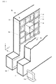
- FIG. 1 An overall perspective diagram of an automated warehouse system 20 according to the first embodiment is illustrated in FIG. 1 . To enable easy viewing of the movable platform 50, the drawing omits a portion of the storage shelf 100.
- the automated warehouse system 20 has a pair of storage shelves 100 having a plurality of storage areas RC.
- the storage shelves 100 have storage areas RC wherein loads BG are stored, and storage areas RC wherein loads BG are not yet stored.
- a movable platform 50 transfers a load BG from a loading/unloading port 101 (referencing FIG. 2 ) to a specific storage area RC, or transfers a load BG that is stored in a storage area RC to the loading/unloading port 101, following a movement instruction from a controlling portion MA.
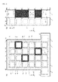
- FIG. 2 (A) is a side view diagram, viewed from the Y direction, of one of a pair of storage shelves 100
- FIG. 2 (B) is a side view diagram, viewed from the X direction, a pair of storage shelves 100.
- the storage shelf 100 is built from a plurality of support pillars 103 that extend in the Z direction and a plurality of beams 105 that extend in the horizontal direction.
- a plurality of storage areas RC is formed from these support pillars 103 and beams 105.
- the number of levels and number of columns of storage areas RC are arbitrary, and may be increased or decreased as appropriate depending on the installation space.
- Loading/unloading ports 101, for transferring loads BG to the movable platform 50 or transferring loads BG from the movable platform 50 are provided on the left and right of the shelf at the bottommost level (on the -Z side).
- Guide rails 110 that extend in the vertical and horizontal directions are disposed on the support pillars 103 and beams 105.
- the guide rails 110 have shaft rails 110A, of a narrow width, that are disposed on the outside of the individual storage areas RC, and roller rails 110B, of a wide width, that are disposed on the insides of the individual storage areas RC (referencing FIG. 3 ).
- the guide rollers 52 of the movable platform 50 enter into the roller rail 110B.
- a plurality of locking holes 112 is formed in the guide rails 110 that extend horizontally. As illustrated in FIG. 2 (A) , the locking holes 112 are formed at the top and bottom of each individual storage area RC near the center of the storage area RC in the X direction.
- the movable platform 50 is of a size that essentially matches the size of the storage area RC (the XZ plane).
- the movable platform 50 has a frame body 51. At least one face of the frame body 51 in the Y direction is open so as to enable the load BG to be transferred in and out.
- eight guide rollers 52 are provided for a single frame body 51. In order to be supported from the pair of storage shelves 100, four guide rollers 52 are disposed in the -Y direction from the frame body 51 (where two guide rollers 52 are illustrated in FIG. 2 (B) ), and four guide rollers 52 are disposed in the +Y direction from the frame body 51 (where two guide rollers 52 are illustrated in FIG.
- a plurality of movable platforms 50 is disposed in the storage shelf 100.
- a plurality of movable platforms 50 can be provided in the storage shelf 100. Because of this, the number of movable platforms 50 can be adjusted depending on the frequency with which the loads BG are transferred.
- FIG. 3 is an enlarged side view diagram, viewed from the Y direction, of a storage shelf 100 and a movable platform 50.
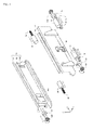
- FIG. 4 is a diagram illustrating guide rollers 52 (52C, 52D, and 52E), a locking pin 58, and a picker 60, and the like, provided on a movable platform 50.
- the frame body 51 of the movable platform 50 is not shown, to facilitate viewing of the guide rollers 52.
- the movable platform 50 illustrated by the dotted line, is drawn in the state wherein it is in motion from one storage area RC to another storage area RC, and the movable platform 50 that is illustrated with the solid lines is drawn in a state wherein it can transfer a load out of or into a single storage area RC.
- the guide rollers 52 are driven by a driving motor 55 (referencing FIG. 4 ) based on an instruction from a controlling portion MA (referencing FIG. 1 ).
- the movable platform 50 has a location sensor SE at the Z-direction center of the left and right edges of the frame interior 51.
- Location indicators PO which are subject to location detection by the location sensor SE, are disposed on the support pillars 103.
- the movable platform 50 is at a storage area RC, at a location wherein the load BG can be transferred in or out.
- a pair of pickers 60 is disposed on the inside of the frame interior 51.
- the pair of pickers 60 transfers a load BG from the frame interior 51 into the storage area RC, and transfers a load BG out of the storage area RC to the frame interior 51.
- a picker 60 has a stationary frame 61 and a movable frame 62.
- the movable frame 62 is moved by a picker driving portion 65, such as a motor that is built into the stationary frame 61.
- the picker driving portion 65 moves the movable frame 62 in the ⁇ Y directions.
- Each of the pair of movable frames 62 has respective pawl members 63 (63A and 63B).
- the pawl member 63A is illustrated in the laid-flat state and the pawl member 63B is illustrated in the erect state.
- the pawl members 63 (63A and 63B) are formed in L shapes, in the plan view, where the pawl members 63 are attached so as to be able to pivot relative to a support shaft (not shown) that is provided on the movable frame 62.
- a driving portion not shown, switches the pawl members 63 between a state that is erect in the X direction and a state that is laid flat.
- the pair of pawl members 63B on the +Y side are erect in the X direction, and when, in this state, the movable frame 62 is driven in the -Y direction, the pawl members 63B push the load BG in the -Y direction. This enables the picker 60 to transfer the load BG from the movable platform 50 to the storage area RC.
- the pawl members 63A are caused to be erect in the X direction, and when, in this state, the movable frame 62 returns in the +Y direction, the pawl members 63B pull the load BG from the storage area RC to the movable platform 50.
- the movable platform 50 has locking pins 58 in the X-direction centers of the top and bottom edges of the frame interior 51. Moreover, on the beams 105, locking holes 112 are formed in the center location for each storage area RC in the guide rails 110 that extend in the horizontal direction. A locking pin 58 can be inserted into a locking hole 112.
- an actuator 59 such as an electromagnetic solenoid, is attached to the locking pin 58.
- the locking pin 58 is moved in the ⁇ Y directions by the actuator 59.
- the guide rollers 52 (52A through 52D) are disposed at four corners of the frame body 51 on the XZ plane.
- the four guide rollers 52A through 52D are located at the points of intersection between the guide rails 110 that extend in the vertical direction and the guide rails 110 that extend in the horizontal direction.
- a total of eight guide rollers 52 are disposed at the corners of the frame body 51. Because of this, the movable platform 50 can move in both the Z direction and the X direction.
- the guide rollers 52 are connected to rotating shafts 56 of a driving motor 55.
- the rotating shafts 56 are supported by thrust bearings 53.
- the driving motor 55 rotates the guide rollers 52 in the clockwise or counterclockwise direction, as indicated by the rotation arrow marks.
- the driving motor 55 is mounted on a Y-axis movable table 54.
- the Y-axis movable table 54 can be moved in the ⁇ Y directions by driving means, not shown. Because of this, the driving motor 55 can be moved in the ⁇ Y directions and the rotating shafts 56 can also be moved in the ⁇ Y direction by the thrust bearings 53. That is, the guide rollers 52 can be moved in the ⁇ Y directions.
- the movable platform 50 as illustrated in FIG. 2 (B) is held between a pair of storage shelves 100. Both guide rollers 52C and 52E can be moved in the ⁇ Y direction by a Y-axis movable table 54 on both storage shelf 100 sides. Moreover, the driving motor 55 is able to vary the speed of rotation of the guide rollers 52 by varying the driving pulses or electric current. Because of this, the controlling portion MA (referencing FIG. 1 ) is able to vary the movement speed of the movable platform 50.
- FIG. 5 will be used next to explain the operation of the guide rollers 52 and the locking pins 58.
- FIG. 3 when the movable platform 50 that is indicated by the solid line transfers a load into or out of a storage area RC, if no rotational forces are applied to the guide rollers 52, then there would be a danger that the movable platform 50 would fall in the -Z direction under its own weight. Continuously applying rotational forces to the guide rollers 52 would place a large load on the driving motor 55. Given this, the movable platform 50 is supported by the guide rollers 52 and the locking pins 58 so that the movable platform 50 will be maintained in the location illustrated by the solid lines, even if the driving motor 55 is stopped.
- FIG. 5 is a diagram illustrating the relationships between the guide rollers 52 (52C and 52D), the locking pins 58, and the guide rails 110 that are formed on the beams 105.
- FIG. 5 (A) and (B) are of the state wherein a side face 52K on the Y side of the guide roller 52 is in contact with the roller rail 110B, and the locking pin 58 is inserted in a locking hole 112. Note that, FIG. 5 (A) is the view when seen from the Z direction, and (B) is the view when seen from the X direction.
- FIG. 5 is the view when seen from the Z direction
- FIG. 5 (B) is the view when seen from the X direction.
- FIG. 5 (C) and (D) show the state wherein the guide rollers 52 are located in the Y-direction center of the roller rails 110B, and the locking pins 58 have been removed from the locking holes 112. Note that, FIG. 5 (C) is the view when seen from the Z direction, and (D) is the view when seen from the X direction.
- the Y-axis movable table 54 moves the guide rollers 52 in the -Y direction. Following this, the side faces 52K of the guide rollers 52 make contact with the roller rail 110B.
- the Y-axis movable table 54 on the side of the other storage shelf 100 not shown, moves the guide rollers 52 (such as the guide roller 52E of FIG. 4 ) in the +Y direction. Because of this, the four guide rollers 52 on the side of one of the storage shelves 100 (where, in FIG.
- the locking pins 58 are moved in the -Y direction by actuators 59 on the side of one of the storage shelves 100.
- the locking pins 58 are moved in the +Y direction by actuators 59 on the side of one of the other storage shelf 100.
- the respective locking pins 58 are inserted into the locking holes 112 in the guide rails 110. Because of this, the movable platform 50 is locked at the location indicated by the solid lines.
- the guide rollers 52 are in locations that do not make contact with the roller rails 110B.
- the eight guide rollers 52 support the movable platform 50 in the Z direction in the roller rails 110B that extend in the horizontal direction of the beams 105. Note that the locking pins 58 are removed from the locking holes 112 of the guide rails 110.
- FIG. 6 is a flowchart illustrating the operation for transferring a load BG into or out of storage by the automated warehouse system 20. An operation wherein a single movable platform 50 transfers a load BG to a storage area RC and transfers another load BG from a storage area RC will be explained using this flowchart.
- Step S11 the movable platform 50 transfers a load BG at the loading/unloading port 101 (referencing FIG. 2 ).
- Step S12 the guide rollers 52 are rotated in accordance with an instruction from the controlling portion MA to move the movable platform 50 to a specific storage area RC.
- the location sensor SE detects the location indicators PO.
- the location sensor SE sends a signal to the controlling portion MA, and the controlling portion MA confirms the location of the movable platform 50 during movement.
- Step S 13 the controlling portion MA is sent a signal from the location sensor SE, and checks whether or not the movable platform 50 is moving correctly to the specific storage area RC. With the location sensor SE and the location indicator PO facing each other, the controlling portion MA confirms that the movable platform 50 is at a location at the storage area RC wherein the load BG can be moved out.
- Step S 14 the controlling portion MA instructs the actuators 59 to cause the two locking pins 58 to extend.
- the locking pins 58 are inserted into the locking holes 112 of the guide rails 110.
- the controlling portion MA moves four guide rollers 52 in the +Y direction and the other four guide rollers 52 in the -Y direction, to cause the side faces 52K of the guide rollers 52 to make contact with the wall faces within the roller rails 110B. Doing so causes the movable platform 50 to be in a state wherein it is secured relative to the storage area RC.
- Step S15 the pickers 60 insert the load BG into the storage area RC from the frame body 51 of the movable platform 50.
- Step S16 the pickers 60 retract back to the movable platform 50 with the load BG still remaining within the storage area.
- Step S 17 the locking pins 58, which had been extended, are returned to the frame body 51 side of the movable platform 50, so that the movable platform 50 can move to the next storage area RC.
- the guide rollers 52 are moved in the Y direction to move the side faces 52K of the guide rollers 52 away from the roller rail 110B wall faces.
- the guide rollers 52 move to essentially the center of the roller rails 110B in the thickness direction.
- Step S18 the guide rollers 52 are rotated by the driving motor 55 to move the movable platform 50 to the next storage area RC.
- the location sensor SE detects the location indicators PO.
- the location sensor SE sends a signal to the controlling portion MA, and the controlling portion MA monitors the location of the movable platform 50 during movement.
- Step S19 the controlling portion MA checks, through the signal from the location sensor SE, whether or not the movable platform 50 has moved correctly to the next storage area RC.
- Step S20 the locking pins 58 are extended and the locking pins 58 are inserted into the locking holes 112.
- the guide rollers 52 are moved in the Y direction so that the side faces 52K thereof make contact with the wall faces within the roller rails 110B.
- Step S21 the pickers 60 are moved in the Y direction (or, more precisely, the movable frames 62 of the pickers 60 are moved relative to the stationary frames 61), to enter into the storage area RC. After this, the pawl members 63 are erected in the X direction.
- Step S22 the load BG is caught on the pawl members 63 of the pickers 60 and the load BG is transferred into the frame body 51 of the movable platform 50 from the storage area RC.
- Step S23 the locking pins 58 that had been protruding are returned to the frame body 51 side of the movable platform 50 so that the movable platform 50 can return to the loading/unloading port 101. Similarly, the guide rollers 52 are moved to essentially the center of the roller rails 110B in the thickness direction.
- Step S24 the guide rollers 52 are rotated in accordance with an instruction from the controlling portion MA, and the movable platform 50 moves to the loading/unloading port 101.
- Step S25 the load BG is transferred out from the movable platform 50 by the loading/unloading port 101.
- the guide rollers 152 which will be explained next, are a modified example of the guide rollers 52.
- FIG. 7 is an enlarged side view diagram, viewed from the Y direction, of a storage shelf 100 and a movable platform 50.
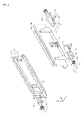
- FIG. 8 is a diagram illustrating a guide roller 152 and a picker 60, and the like, that are provided on the movable platform 50.
- the frame body 51 of the movable platform 50 is not illustrated, to facilitate viewing of the guide roller 152.
- the structure of the pickers 60 is identical to that which was explained using FIG. 5 , so explanations thereof will be omitted.
- the movable platform 50 is drawn in the state wherein it is moving in the horizontal direction from one storage area RC to another storage area RC.
- the movable platform 50 is drawn in the state wherein it is moving in the vertical direction from one storage area RC to another storage area RC.
- the guide rollers 152 (152A through 152D) are disposed at four corner portions of the frame body 51 in an XZ plane. As was illustrated with FIG. 2 , the movable platform 50 is held between a pair of storage shelves 100, and thus a total of eight guide rollers 52 are disposed at the corner portions of the frame body 51. In this state, the movable platform 50 is able to move in the ⁇ Z direction.
- the guide rollers 152 (152A through 152D) are moved to the center region of the edge, in the horizontal direction, of the XZ plane. As illustrated in FIG. 7 , the guide roller 152A moves a distance of LL1 in the +X direction, and the guide roller 152B moves a distance of LL1 in the -X direction. The guide roller 152C moves a distance of LL2 in the +X direction, and the guide roller 152D moves a distance of LL2 in the -X direction. The distances LL1 and LL2 are different.
- the distances LL1 and LL2 were the same, then when the two guide rollers 152A and 152C come to an intersection between the guide rails 110 that extend in the vertical direction and the guide rails 110 that extend in the horizontal direction, it would be necessary to support the movable platform 50 in the Z direction by the two guide rollers 152B and 152D (for a total of 4, including those on the side of the other storage shelf).
- the movable platform 50 can be supported in the Z direction by at least three rollers 152 (a total of six, including those on the side of the other storage shelf).
- the guide roller 152 is connected to the rotational shaft 56 of the driving motor 55.
- the rotational shaft 56 is supported by a thrust bearing 53.
- the guide rollers 152 are rotated in the clockwise direction or the counterclockwise direction by the rotation of the driving motor 55.
- the thrust bearing 53 and the driving motor 55 are mounted on an X-axis movable table 154.
- the X-axis movable table 154 can be moved by a distance LL1 or a distance LL2 in the ⁇ X directions by driving means, not shown. Because of this, the driving motor 55 is moved in the ⁇ X directions, and the guide roller 152 can be moved by a distance of LL1 or LL2 in the ⁇ X directions.
- the movable platform 50 is held between a pair of storage shelves 100.
- the guide rollers can be moved in the ⁇ X directions, together with 152C and 152E, by the X-axis movable table 154 on both storage shelf 100 sides.
- An automated warehouse system 22 has a plurality of storage shelves 100 (100A through 100D).
- FIG. 9 is a side view diagram, viewed from the X direction, of the automated warehouse system 22.
- the automated warehouse system 22 has four storage shelves 100 (100A through 100D), having a plurality of storage areas RC.
- a plurality of movable platforms 50 is disposed between the storage shelves 100A and 100B.
- a plurality of movable platforms 50 is disposed between the storage shelves 100B and 100C, and a plurality of movable platforms 50 is disposed between the storage shelves 100C and 100D.
- the Y-direction width WY1 of the storage shelves 100 and the Y-direction width WY2 of the movable platforms 50 are essentially identical.
- the storage shelf 100B and the storage shelf 100C each have a plurality of movable platforms 50 disposed on both sides of each. Moreover, as illustrated in FIG. 4 or FIG. 8 , the pickers 60 (or more precisely, the movable frames 62) can be moved in the ⁇ Y directions, relative to the stationary frames 61, by the picker driving portions 65. Because of this, the movable platforms 50 on the left side (the -Y direction side) of the storage shelf 100B are able to transfer loads BG into and out of the storage shelf 100B. Furthermore, the movable platforms 50 on the right side (the +Y direction side) of the storage shelf 100B are able to transfer loads BG into and out of the storage shelf 100B. The same is true for the movable platforms 50 on both sides of the storage shelf 100C.
- the number of storage shelves 100 may be, of course, more than 4.
- An automated warehouse system 24 has a plurality of storage shelves 100 (100A through 100D).
- FIG. 10 is a side view diagram, viewed from the X direction, of the automated warehouse system 24.
- the automated warehouse system 24 has four storage shelves 100 (100A through 100D), having a plurality of storage areas RC.
- a plurality of movable platforms 50 is disposed between the storage shelves 100A and 100B.
- the storage shelf 100B and the storage shelf 100C are adjoining each other, with no room for a movable platform 50.
- a plurality of movable platforms 50 is disposed between the storage shelves 100C and 100D.
- the Y-direction width WY1 of the storage shelves 100 and the Y-direction width WY2 of the movable platforms 50 are essentially identical.
- the movable platforms 50 on the left side (the -Y direction side) of the storage shelf 100B are able to transfer loads BG into and out of the storage shelf 100B.
- the movable platforms 50 on the right side (the +Y direction side) of the storage shelf 100C are able to transfer loads BG into and out of the storage shelf 100C. Because of this, even though the storage shelves 100B and storage shelf 100C are adjoining each other, and there are no movable platforms 50 between the storage shelves 100B and storage shelf 100C, it is still possible to retrieve loads BG. If there is a large number of storage shelves 100 lined up together, this makes it possible to reduce the width WY2 in the Y direction of the movable platform 50, which enables limited space the used efficiently.
- the automated warehouse system 26 according to the fourth embodiment has a storage shelf 130.
- FIG. 11 is a side view diagram, viewed from the Y direction, of the automated warehouse system 26. Those parts that are identical to those in the first embodiment are assigned identical codes.
- the storage shelf 130 is built from a plurality of support pillars 103 that extend in the Z direction and a plurality of beams 105 that extend in the horizontal direction.
- a plurality of storage areas RC is formed from these support pillars 103 and beams 105.
- guide rails 110 and locking holes 112 are formed.
- the number of levels and number of columns of storage areas RC are arbitrary, and may be increased or decreased as appropriate depending on the installation space.
- Loading/unloading ports 107, for transferring loads BG to the movable platform 150 or transferring loads BG from the movable platform 150 are provided on the left and right of the shelf at the bottommost level (on the -Z side). This loading/unloading port 107 is provided with a size that is twice that of a storage area, so as to match the size of the movable platform 150.
- the movable platform 150 is of a size that essentially matches the size of two storage areas RC lined up in the horizontal direction (the XZ plane).
- the movable platform 150 has a frame body 151. At least two faces of the frame body 151 in the Y direction is open so as to enable loads BG to be transferred in and out. Moreover, 12 guide rollers 52 are provided for a single frame body 151.
- the movable platform 150 can transfer twice the load BG. While in the fourth embodiment, the movable platform 150 has twice the storage area in the horizontal direction, the storage area may be three or more times as much instead. Moreover, the movable platform 150 may also have two or three times the storage area lined up in the vertical direction.
- the automated warehouse system 28 has a storage shelf 140.
- FIG. 12 is a side view diagram, viewed from the Y direction, of the automated warehouse system 28. Those parts that are identical to those in the first embodiment are assigned identical codes.
- the building that houses the automated warehouse system may have a slanted roof, or may have a plurality of beams.
- usually conventional storage shelves would be essentially rectangular when viewed from the Y direction. Given this, the space between the ceiling and the storage shelves, or the spaces between the beams and the storage shelves, would not be used effectively.
- the fifth embodiment is an example wherein the storage shelves 140 use the space between the ceiling and the storage shelves, and the spaces between the beams and the storage shelves, effectively.
- the storage shelf 140 is built from a plurality of support pillars 103 that extend in the Z direction and a plurality of beams 105 that extend in the horizontal direction.
- a plurality of storage areas RC is formed from these support pillars 103 and beams 105.
- guide rails 110 and locking holes 112 are formed.
- the ceiling RF is slanted, and there are lateral beams BM that extend in the Y direction.
- the support pillars 103 and the beams 105 are assembled in a range wherein they do not conflict with the ceiling RF or the lateral beams BM.
- storage areas RC are formed even in the space on the left side of the ceiling RF, and storage areas RC are formed also above the lateral beams BM.
- the scope of movement of the stacker crane in the Z direction and in the X direction is limited to the height of the lowest ceiling RF in a range wherein there are no lateral beams BM.
- the movable platforms 50 travel along the guide rails 110 that are disposed on the support pillars 103 and the beams 105, they are able to move in whatever range the support pillars 103 and beams 105 are assembled together.
- the present invention may be embodied, within the scope of technology thereof, with a variety of changes and modifications to these embodiments.
- the locking pins and guide rollers were moved in the Y directions so as to not cause a load on the driving motor, instead either the locking pins or the guide rollers, or both, may be moved in the Y directions.
- the movable platform was held between the storage shelves and was supported by eight guide rollers, instead the movable platform may be supported on one side by four guide rollers.
Landscapes
- Engineering & Computer Science (AREA)
- Mechanical Engineering (AREA)
- Warehouses Or Storage Devices (AREA)
- Physics & Mathematics (AREA)
- Mathematical Physics (AREA)
Abstract
Description
- The present invention relates to an automated warehouse system, and, in particular, relates to an automated warehouse system for transferring loads that are stored in a storage area.
- Conventional automated warehouse systems usually used load elevator-type stacker cranes as the transfer means. These stacker cranes are driven along travel guide rails, and are structured so as to move up and down along a guide frame portion that is disposed perpendicularly in relation to the travel guide rails. To enable the stacker crane to move in relation to a plurality of storage areas that are arranged in a line, the travel guide rails are laid, from end to end, along the storage areas that are disposed in a line. An automated storage system that uses such a stacker crane requires a large amount of space. Moreover, often it is only possible to provide a single stacker crane for a single travel guide rail. In automated warehouse systems there is the need to save space and to make the systems more compact, and it is desirable that the size, including the stacker crane and a plurality of storage areas, be small.
- Patent Citation 1: Japanese Unexamined Patent Application Publication
2008-100848 - However, when a load elevator-type stacker crane is used as the transfer means in an automated warehouse system, it is necessary to provide movement rails for the stacker crane, which has limited the ability to reduce the space in the warehouse. Moreover, when a plurality of stacker cranes are provided due to a high demand for transfer of loads, it becomes necessary to provide other movement rails as well, making space reduction difficult.
- Given this, the present invention provides a space-saving automated warehouse system.
- An automated warehouse system according to a first aspect stores loads in a plurality of storage areas built from a plurality of support pillars that extend in the vertical direction and a plurality of beams that extend in the horizontal direction, transfers loads to a plurality of storage areas and transfers from the plurality of storage areas. The automated warehouse system is provided with a movable platform having a frame body that has a vertical frame and a horizontal frame of a rectangular shape that is the same as at least one of said storage areas, and a guide roller that engages with the vertical guide rail that is disposed on the vertical frame or the horizontal guide rail that is disposed on the horizontal frame.
- Because the movable platform advances along the vertical guide rails and lateral guide rails, there is no need to provide travel guide rails for a stacker crane on the floor. Moreover, this also enables the provision of a plurality of movable platforms on the vertical guide rails and the lateral guide rails.
- In an automated warehouse system according to a second aspect, the movable platform has a picker for sliding the load to transfer the load from the movable platform into the storage area, and to slide the load to transfer the load out of the storage area to the movable platform.
- In an automated warehouse system according to a third aspect, the guide roller is disposed at a corner portion of a rectangular frame body, and can move in a direction that is perpendicular to the vertical guide rail and the horizontal guide rail; and when the load is transferred in or transferred out, the guide roller is pushed to contact a vertical guide rail or a horizontal guide rail. This causes the movable platform to be secured to the storage area.
- An automated warehouse system according to a fourth aspect has a locking device for locking together the horizontal guide rail and the movable platform when transferring a load in or transferring a load out. This causes the movable platform to be secured to the storage area.
- In an automated warehouse system according to a fifth aspect, the guide roller is able to move from an edge of the frame body in the horizontal direction to a corner portion of the rectangular shape of the frame body; wherein: when transferring a load in or transferring a load out, when the movable platform is moved in the lateral direction, the guide roller is located at a center region of the edge in the horizontal direction, and when the movable platform is moved in the vertical direction, the guide roller is located at a corner portion.
- In an automated warehouse system according to a sixth aspect, the guide roller includes a first guide roller and a second guide roller, where the movement distance of the first guide roller from the center region to the corner portion and the movement distance of the second guide roller from the center region to the corner portion are mutually different.
- In an automated warehouse system according to a seventh aspect, the movable platform is disposed between a first storage shelf, made from a plurality of storage areas, and a second storage shelf, made from a plurality of storage areas, disposed so as to face the first storage shelf, and guide rollers are disposed on the first storage shelf side and the second storage shelf side.
- In an automated warehouse system according to an eighth aspect, the movable platform is disposed between a third storage shelf, made from a plurality of storage areas, and a second shelf, made from a plurality of storage areas, disposed so as to face the fourth storage shelf, and the second storage shelf and the third storage shelf are disposed adjoining each other.
- In an automated warehouse system according to a ninth aspect, the movable platform has a frame body corresponding to a plurality of adjoining storage areas.
- The automated warehouse system according to the present invention enables transfer of loads into a storage area, and transfer of loads from the storage area, with a small floorspace.
-
-
FIG. 1 is a perspective diagram of a first conveyor transfer device 100. -
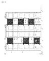
FIG. 2 (A) is a side view diagram, viewed from the Y direction, of one of a pair of storage shelves 100. (B) is a side view diagram, viewed from the X direction, a pair of storage shelves 100. -
FIG. 3 is a side view enlarged diagram, viewed from the Y direction, of a storage shelf 100 and amovable platform 50. -
FIG. 4 is a diagram illustrating aguide roller 52, a locking pin 58, a picker 60, etc. -
FIG. 5 is a diagram illustrating the relationship between theguide roller 52, the locking pin 58, and a guide rail 110 that is formed on abeam 105. -
FIG. 6 is a flowchart illustrating the operation in transferring loads BG in and out using anautomated warehouse system 20. -
FIG. 7 is a side view enlarged diagram, viewed from the Y direction, of a storage shelf 100 and amovable platform 50. -
FIG. 8 is a diagram illustrating a guide roller 152 and a picker 60. -
FIG. 9 is a diagram illustrating anautomated warehouse system 22 according to a second embodiment. -
FIG. 10 is a diagram illustrating anautomated warehouse system 24 according to a third embodiment. -
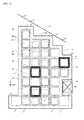
FIG. 11 is a diagram illustrating an automated warehouse system 26 according to a fourth embodiment. -
FIG. 12 is a diagram illustrating anautomated warehouse system 28 according to a fifth embodiment. - (First Embodiment) A first embodiment will be explained below based on the appended drawings.
- An overall perspective diagram of an
automated warehouse system 20 according to the first embodiment is illustrated inFIG. 1 . To enable easy viewing of themovable platform 50, the drawing omits a portion of the storage shelf 100. - As illustrated in
FIG. 1 , theautomated warehouse system 20 according to the first embodiment has a pair of storage shelves 100 having a plurality of storage areas RC. The storage shelves 100 have storage areas RC wherein loads BG are stored, and storage areas RC wherein loads BG are not yet stored. Amovable platform 50 transfers a load BG from a loading/unloading port 101 (referencingFIG. 2 ) to a specific storage area RC, or transfers a load BG that is stored in a storage area RC to the loading/unloading port 101, following a movement instruction from a controlling portion MA. -
FIG. 2 (A) is a side view diagram, viewed from the Y direction, of one of a pair of storage shelves 100, andFIG. 2 (B) is a side view diagram, viewed from the X direction, a pair of storage shelves 100. - As illustrated in
FIG. 2 (A) , the storage shelf 100 is built from a plurality ofsupport pillars 103 that extend in the Z direction and a plurality ofbeams 105 that extend in the horizontal direction. A plurality of storage areas RC is formed from thesesupport pillars 103 andbeams 105. The number of levels and number of columns of storage areas RC are arbitrary, and may be increased or decreased as appropriate depending on the installation space. Loading/unloading ports 101, for transferring loads BG to themovable platform 50 or transferring loads BG from themovable platform 50 are provided on the left and right of the shelf at the bottommost level (on the -Z side). - Guide rails 110 that extend in the vertical and horizontal directions are disposed on the
support pillars 103 andbeams 105. The guide rails 110 have shaft rails 110A, of a narrow width, that are disposed on the outside of the individual storage areas RC, and roller rails 110B, of a wide width, that are disposed on the insides of the individual storage areas RC (referencingFIG. 3 ). Theguide rollers 52 of themovable platform 50 enter into the roller rail 110B. A plurality oflocking holes 112 is formed in the guide rails 110 that extend horizontally. As illustrated inFIG. 2 (A) , thelocking holes 112 are formed at the top and bottom of each individual storage area RC near the center of the storage area RC in the X direction. - As illustrated in
FIG. 2 (A) and (B) , themovable platform 50 is of a size that essentially matches the size of the storage area RC (the XZ plane). Themovable platform 50 has a frame body 51. At least one face of the frame body 51 in the Y direction is open so as to enable the load BG to be transferred in and out. Moreover, eightguide rollers 52 are provided for a single frame body 51. In order to be supported from the pair of storage shelves 100, fourguide rollers 52 are disposed in the -Y direction from the frame body 51 (where twoguide rollers 52 are illustrated inFIG. 2 (B) ), and fourguide rollers 52 are disposed in the +Y direction from the frame body 51 (where twoguide rollers 52 are illustrated inFIG. 2 (B) ). These eightguide rollers 52 are located within the roller rail 110RB of the guide rail 110. The diameter of theguide roller 52 is larger than the width of the shaft rail 110A, and thus theguide roller 52 does not fall out of the guide rail 110 (referencingFIG. 3 ). Moreover, because the size of the load BG that is transferred by themovable platform 50 is the same as the size of the load BG that is stored in the storage area RC, the width WY1 of the storage shelf 100 in the Y direction is essentially the same as the width WY2 of themovable platform 50 in the Y direction. - As illustrated in
FIG. 2 (A) and (B) , a plurality ofmovable platforms 50 is disposed in the storage shelf 100. In the conventional automated warehouse system, usually only a single stacker crane could be provided for a single travel guide rail. Because of this, the only way to increase the efficiency with which the loads BG are transferred was to increase the speed of the stacker crane itself. However, in the present embodiment, a plurality ofmovable platforms 50 can be provided in the storage shelf 100. Because of this, the number ofmovable platforms 50 can be adjusted depending on the frequency with which the loads BG are transferred. -
FIG. 3 is an enlarged side view diagram, viewed from the Y direction, of a storage shelf 100 and amovable platform 50. Moreover,FIG. 4 is a diagram illustrating guide rollers 52 (52C, 52D, and 52E), a locking pin 58, and a picker 60, and the like, provided on amovable platform 50. InFIG. 4 , the frame body 51 of themovable platform 50 is not shown, to facilitate viewing of theguide rollers 52. - In
FIG. 3 , themovable platform 50, illustrated by the dotted line, is drawn in the state wherein it is in motion from one storage area RC to another storage area RC, and themovable platform 50 that is illustrated with the solid lines is drawn in a state wherein it can transfer a load out of or into a single storage area RC. Theguide rollers 52 are driven by a driving motor 55 (referencingFIG. 4 ) based on an instruction from a controlling portion MA (referencingFIG. 1 ). - The
movable platform 50 has a location sensor SE at the Z-direction center of the left and right edges of the frame interior 51. Location indicators PO, which are subject to location detection by the location sensor SE, are disposed on thesupport pillars 103. When the location sensor SE and the location indicator PO are at coincident locations, themovable platform 50 is at a storage area RC, at a location wherein the load BG can be transferred in or out. - In the
movable platform 50, a pair of pickers 60 is disposed on the inside of the frame interior 51. The pair of pickers 60 transfers a load BG from the frame interior 51 into the storage area RC, and transfers a load BG out of the storage area RC to the frame interior 51. - As illustrated in
FIG. 4 , a picker 60 has a stationary frame 61 and a movable frame 62. The movable frame 62 is moved by a picker driving portion 65, such as a motor that is built into the stationary frame 61. The picker driving portion 65 moves the movable frame 62 in the ±Y directions. - Each of the pair of movable frames 62 has respective pawl members 63 (63A and 63B). In
FIG. 4 , in one of the movable frames 62, the pawl member 63A is illustrated in the laid-flat state and the pawl member 63B is illustrated in the erect state. The pawl members 63 (63A and 63B) are formed in L shapes, in the plan view, where the pawl members 63 are attached so as to be able to pivot relative to a support shaft (not shown) that is provided on the movable frame 62. A driving portion, not shown, switches the pawl members 63 between a state that is erect in the X direction and a state that is laid flat. - In a state wherein a load BG has been placed on the
movable platform 50, the pair of pawl members 63B on the +Y side are erect in the X direction, and when, in this state, the movable frame 62 is driven in the -Y direction, the pawl members 63B push the load BG in the -Y direction. This enables the picker 60 to transfer the load BG from themovable platform 50 to the storage area RC. On the other hand, in a state wherein the movable frame 62 has advanced far in the -Y direction (relative to the storage area RC), the pawl members 63A are caused to be erect in the X direction, and when, in this state, the movable frame 62 returns in the +Y direction, the pawl members 63B pull the load BG from the storage area RC to themovable platform 50. - Returning to
FIG. 3 , themovable platform 50 has locking pins 58 in the X-direction centers of the top and bottom edges of the frame interior 51. Moreover, on thebeams 105, lockingholes 112 are formed in the center location for each storage area RC in the guide rails 110 that extend in the horizontal direction. A locking pin 58 can be inserted into alocking hole 112. - Moreover, as illustrated in
FIG. 4 , an actuator 59, such as an electromagnetic solenoid, is attached to the locking pin 58. The locking pin 58 is moved in the ±Y directions by the actuator 59. - Returning again to
FIG. 3 , the guide rollers 52 (52A through 52D) are disposed at four corners of the frame body 51 on the XZ plane. In themovable platform 50 that is illustrated with the solid lines, the four guide rollers 52A through 52D are located at the points of intersection between the guide rails 110 that extend in the vertical direction and the guide rails 110 that extend in the horizontal direction. As illustrated inFIG. 2 , because themovable platform 50 is held between a pair of storage shelves 100, a total of eightguide rollers 52 are disposed at the corners of the frame body 51. Because of this, themovable platform 50 can move in both the Z direction and the X direction. When moving in the ±Z direction, the two guide rollers 52A and 52C rotate in the clockwise direction, and the two guide rollers 52B and 52D rotate in the counterclockwise direction. When moving in the +X direction, the four guide rollers 52A through 52D rotate in the clockwise direction. When moving in the -X direction, the four guide rollers 52A through 52D rotate in the counterclockwise direction. - Moreover, as illustrated in
FIG. 4 , theguide rollers 52 are connected to rotating shafts 56 of a driving motor 55. The rotating shafts 56 are supported by thrust bearings 53. By rotating, the driving motor 55 rotates theguide rollers 52 in the clockwise or counterclockwise direction, as indicated by the rotation arrow marks. Moreover, the driving motor 55 is mounted on a Y-axis movable table 54. The Y-axis movable table 54 can be moved in the ±Y directions by driving means, not shown. Because of this, the driving motor 55 can be moved in the ±Y directions and the rotating shafts 56 can also be moved in the ±Y direction by the thrust bearings 53. That is, theguide rollers 52 can be moved in the ±Y directions. - Note that the
movable platform 50, as illustrated inFIG. 2 (B) is held between a pair of storage shelves 100. Both guide rollers 52C and 52E can be moved in the ±Y direction by a Y-axis movable table 54 on both storage shelf 100 sides. Moreover, the driving motor 55 is able to vary the speed of rotation of theguide rollers 52 by varying the driving pulses or electric current. Because of this, the controlling portion MA (referencingFIG. 1 ) is able to vary the movement speed of themovable platform 50. -
FIG. 5 will be used next to explain the operation of theguide rollers 52 and the locking pins 58. InFIG. 3 , when themovable platform 50 that is indicated by the solid line transfers a load into or out of a storage area RC, if no rotational forces are applied to theguide rollers 52, then there would be a danger that themovable platform 50 would fall in the -Z direction under its own weight. Continuously applying rotational forces to theguide rollers 52 would place a large load on the driving motor 55. Given this, themovable platform 50 is supported by theguide rollers 52 and the locking pins 58 so that themovable platform 50 will be maintained in the location illustrated by the solid lines, even if the driving motor 55 is stopped. -
FIG. 5 is a diagram illustrating the relationships between the guide rollers 52 (52C and 52D), the locking pins 58, and the guide rails 110 that are formed on thebeams 105.FIG. 5 (A) and (B) are of the state wherein a side face 52K on the Y side of theguide roller 52 is in contact with the roller rail 110B, and the locking pin 58 is inserted in alocking hole 112. Note that,FIG. 5 (A) is the view when seen from the Z direction, and (B) is the view when seen from the X direction.FIG. 5 (C) and (D) show the state wherein theguide rollers 52 are located in the Y-direction center of the roller rails 110B, and the locking pins 58 have been removed from the locking holes 112. Note that,FIG. 5 (C) is the view when seen from the Z direction, and (D) is the view when seen from the X direction. - As illustrated in
FIG. 5 (A) and (B) , when themovable platform 50 is at the location illustrated by the solid lines inFIG. 3 , the Y-axis movable table 54 moves theguide rollers 52 in the -Y direction. Following this, the side faces 52K of theguide rollers 52 make contact with the roller rail 110B. The Y-axis movable table 54 on the side of the other storage shelf 100, not shown, moves the guide rollers 52 (such as the guide roller 52E ofFIG. 4 ) in the +Y direction. Because of this, the fourguide rollers 52 on the side of one of the storage shelves 100 (where, inFIG. 5 (A) , the guide rollers 52C and 52D are illustrated) move in the -Y direction, and the fourguide rollers 52 on the side of the other storage shelf 100 move in the +Y direction, to secure themovable platform 50 at the location shown by the solid line. - Moreover, when the
movable platform 50 is at the location indicated by the solid lines inFIG. 3 , the locking pins 58 are moved in the -Y direction by actuators 59 on the side of one of the storage shelves 100. The locking pins 58 are moved in the +Y direction by actuators 59 on the side of one of the other storage shelf 100. The respective locking pins 58 are inserted into the locking holes 112 in the guide rails 110. Because of this, themovable platform 50 is locked at the location indicated by the solid lines. - As illustrated in
FIG. 5 (C) and (D) , when themovable platform 50 is at the location shown by the dotted lines inFIG. 3 (that is, a location other than the location indicated by the solid lines), theguide rollers 52 are in locations that do not make contact with the roller rails 110B. The eightguide rollers 52 support themovable platform 50 in the Z direction in the roller rails 110B that extend in the horizontal direction of thebeams 105. Note that the locking pins 58 are removed from the locking holes 112 of the guide rails 110. -
FIG. 6 is a flowchart illustrating the operation for transferring a load BG into or out of storage by theautomated warehouse system 20. An operation wherein a singlemovable platform 50 transfers a load BG to a storage area RC and transfers another load BG from a storage area RC will be explained using this flowchart. - In Step S11, the
movable platform 50 transfers a load BG at the loading/unloading port 101 (referencingFIG. 2 ). - In Step S12, the
guide rollers 52 are rotated in accordance with an instruction from the controlling portion MA to move themovable platform 50 to a specific storage area RC. At the time of this movement, the location sensor SE detects the location indicators PO. When the location sensor SE has confirmed the location indicator PO, it sends a signal to the controlling portion MA, and the controlling portion MA confirms the location of themovable platform 50 during movement. - In
Step S 13, the controlling portion MA is sent a signal from the location sensor SE, and checks whether or not themovable platform 50 is moving correctly to the specific storage area RC. With the location sensor SE and the location indicator PO facing each other, the controlling portion MA confirms that themovable platform 50 is at a location at the storage area RC wherein the load BG can be moved out. - In
Step S 14, the controlling portion MA instructs the actuators 59 to cause the two locking pins 58 to extend. The locking pins 58 are inserted into the locking holes 112 of the guide rails 110. Following this, the controlling portion MA moves fourguide rollers 52 in the +Y direction and the other fourguide rollers 52 in the -Y direction, to cause the side faces 52K of theguide rollers 52 to make contact with the wall faces within the roller rails 110B. Doing so causes themovable platform 50 to be in a state wherein it is secured relative to the storage area RC. - In Step S15, the pickers 60 insert the load BG into the storage area RC from the frame body 51 of the
movable platform 50. - In Step S16, the pickers 60 retract back to the
movable platform 50 with the load BG still remaining within the storage area. - In
Step S 17, the locking pins 58, which had been extended, are returned to the frame body 51 side of themovable platform 50, so that themovable platform 50 can move to the next storage area RC. Similarly, theguide rollers 52 are moved in the Y direction to move the side faces 52K of theguide rollers 52 away from the roller rail 110B wall faces. Theguide rollers 52 move to essentially the center of the roller rails 110B in the thickness direction. - In Step S18, the
guide rollers 52 are rotated by the driving motor 55 to move themovable platform 50 to the next storage area RC. During movement, the location sensor SE detects the location indicators PO. When the location sensor SE has confirmed a location indicator PO, it sends a signal to the controlling portion MA, and the controlling portion MA monitors the location of themovable platform 50 during movement. - In Step S19, the controlling portion MA checks, through the signal from the location sensor SE, whether or not the
movable platform 50 has moved correctly to the next storage area RC. - In Step S20, the locking pins 58 are extended and the locking pins 58 are inserted into the locking holes 112. The
guide rollers 52 are moved in the Y direction so that the side faces 52K thereof make contact with the wall faces within the roller rails 110B. - In Step S21, the pickers 60 are moved in the Y direction (or, more precisely, the movable frames 62 of the pickers 60 are moved relative to the stationary frames 61), to enter into the storage area RC. After this, the pawl members 63 are erected in the X direction.
- In Step S22, the load BG is caught on the pawl members 63 of the pickers 60 and the load BG is transferred into the frame body 51 of the
movable platform 50 from the storage area RC. - In Step S23, the locking pins 58 that had been protruding are returned to the frame body 51 side of the
movable platform 50 so that themovable platform 50 can return to the loading/unloadingport 101. Similarly, theguide rollers 52 are moved to essentially the center of the roller rails 110B in the thickness direction. - In Step S24, the
guide rollers 52 are rotated in accordance with an instruction from the controlling portion MA, and themovable platform 50 moves to the loading/unloadingport 101. - In Step S25, the load BG is transferred out from the
movable platform 50 by the loading/unloadingport 101. - The guide rollers 152, which will be explained next, are a modified example of the
guide rollers 52. -
FIG. 7 is an enlarged side view diagram, viewed from the Y direction, of a storage shelf 100 and amovable platform 50. Moreover,FIG. 8 is a diagram illustrating a guide roller 152 and a picker 60, and the like, that are provided on themovable platform 50. InFIG. 8 , the frame body 51 of themovable platform 50 is not illustrated, to facilitate viewing of the guide roller 152. Moreover, the structure of the pickers 60 is identical to that which was explained usingFIG. 5 , so explanations thereof will be omitted. - In
FIG. 7 , themovable platform 50, indicated by the dotted lines, is drawn in the state wherein it is moving in the horizontal direction from one storage area RC to another storage area RC. Themovable platform 50, indicated by the solid lines, is drawn in the state wherein it is moving in the vertical direction from one storage area RC to another storage area RC. - When the
movable platform 50 is moved in the vertical direction, the guide rollers 152 (152A through 152D) are disposed at four corner portions of the frame body 51 in an XZ plane. As was illustrated withFIG. 2 , themovable platform 50 is held between a pair of storage shelves 100, and thus a total of eightguide rollers 52 are disposed at the corner portions of the frame body 51. In this state, themovable platform 50 is able to move in the ±Z direction. - When the
movable platform 50 is moved in the horizontal direction, or when the load BG is being transferred out from themovable platform 50 into a storage area RC, the guide rollers 152 (152A through 152D) are moved to the center region of the edge, in the horizontal direction, of the XZ plane. As illustrated inFIG. 7 , theguide roller 152A moves a distance of LL1 in the +X direction, and the guide roller 152B moves a distance of LL1 in the -X direction. The guide roller 152C moves a distance of LL2 in the +X direction, and the guide roller 152D moves a distance of LL2 in the -X direction. The distances LL1 and LL2 are different. If the distances LL1 and LL2 were the same, then when the twoguide rollers 152A and 152C come to an intersection between the guide rails 110 that extend in the vertical direction and the guide rails 110 that extend in the horizontal direction, it would be necessary to support themovable platform 50 in the Z direction by the two guide rollers 152B and 152D (for a total of 4, including those on the side of the other storage shelf). When the distances LL1 and LL2 are different, then themovable platform 50 can be supported in the Z direction by at least three rollers 152 (a total of six, including those on the side of the other storage shelf). - Note that when the load BG is moved out from the
movable platform 50 into the storage area RC, themovable platform 50 is supported in the Z direction by eight guide rollers 152. Because of this, the locking pins 58 are not absolutely necessary. - As illustrated in
FIG. 8 , the guide roller 152 is connected to the rotational shaft 56 of the driving motor 55. The rotational shaft 56 is supported by a thrust bearing 53. The guide rollers 152 are rotated in the clockwise direction or the counterclockwise direction by the rotation of the driving motor 55. Moreover, the thrust bearing 53 and the driving motor 55 are mounted on an X-axis movable table 154. The X-axis movable table 154 can be moved by a distance LL1 or a distance LL2 in the ±X directions by driving means, not shown. Because of this, the driving motor 55 is moved in the ±X directions, and the guide roller 152 can be moved by a distance of LL1 or LL2 in the ±X directions. Note that, as illustrated inFIG. 2 , themovable platform 50 is held between a pair of storage shelves 100. The guide rollers can be moved in the ±X directions, together with 152C and 152E, by the X-axis movable table 154 on both storage shelf 100 sides. - (Second Embodiment) An automated
warehouse system 22 according to a second embodiment has a plurality of storage shelves 100 (100A through 100D).FIG. 9 is a side view diagram, viewed from the X direction, of theautomated warehouse system 22. - The
automated warehouse system 22 according to the second embodiment has four storage shelves 100 (100A through 100D), having a plurality of storage areas RC. A plurality ofmovable platforms 50 is disposed between the storage shelves 100A and 100B. Similarly, a plurality ofmovable platforms 50 is disposed between the storage shelves 100B and 100C, and a plurality ofmovable platforms 50 is disposed between the storage shelves 100C and 100D. The Y-direction width WY1 of the storage shelves 100 and the Y-direction width WY2 of themovable platforms 50 are essentially identical. - The storage shelf 100B and the storage shelf 100C each have a plurality of
movable platforms 50 disposed on both sides of each. Moreover, as illustrated inFIG. 4 orFIG. 8 , the pickers 60 (or more precisely, the movable frames 62) can be moved in the ±Y directions, relative to the stationary frames 61, by the picker driving portions 65. Because of this, themovable platforms 50 on the left side (the -Y direction side) of the storage shelf 100B are able to transfer loads BG into and out of the storage shelf 100B. Furthermore, themovable platforms 50 on the right side (the +Y direction side) of the storage shelf 100B are able to transfer loads BG into and out of the storage shelf 100B. The same is true for themovable platforms 50 on both sides of the storage shelf 100C. - If loads BG that are retrieved often are stored in the storage shelf 100B or 100C, then it is possible to retrieve the loads BG using multiple
movable platforms 50. Although not illustrated inFIG. 9 , the number of storage shelves 100 may be, of course, more than 4. - (Third Embodiment) An automated
warehouse system 24 according to a third embodiment has a plurality of storage shelves 100 (100A through 100D).FIG. 10 is a side view diagram, viewed from the X direction, of theautomated warehouse system 24. - The
automated warehouse system 24 according to the third embodiment has four storage shelves 100 (100A through 100D), having a plurality of storage areas RC. A plurality ofmovable platforms 50 is disposed between the storage shelves 100A and 100B. The storage shelf 100B and the storage shelf 100C are adjoining each other, with no room for amovable platform 50. A plurality ofmovable platforms 50 is disposed between the storage shelves 100C and 100D. The Y-direction width WY1 of the storage shelves 100 and the Y-direction width WY2 of themovable platforms 50 are essentially identical. - Even though the storage shelves 100B and storage shelf 100C are adjoining each other, the
movable platforms 50 on the left side (the -Y direction side) of the storage shelf 100B are able to transfer loads BG into and out of the storage shelf 100B. Additionally, themovable platforms 50 on the right side (the +Y direction side) of the storage shelf 100C are able to transfer loads BG into and out of the storage shelf 100C. Because of this, even though the storage shelves 100B and storage shelf 100C are adjoining each other, and there are nomovable platforms 50 between the storage shelves 100B and storage shelf 100C, it is still possible to retrieve loads BG. If there is a large number of storage shelves 100 lined up together, this makes it possible to reduce the width WY2 in the Y direction of themovable platform 50, which enables limited space the used efficiently. - (Fourth Embodiment) The automated warehouse system 26 according to the fourth embodiment has a
storage shelf 130.FIG. 11 is a side view diagram, viewed from the Y direction, of the automated warehouse system 26. Those parts that are identical to those in the first embodiment are assigned identical codes. - As illustrated in
FIG. 11 , thestorage shelf 130 is built from a plurality ofsupport pillars 103 that extend in the Z direction and a plurality ofbeams 105 that extend in the horizontal direction. A plurality of storage areas RC is formed from thesesupport pillars 103 and beams 105. As with the first embodiment, guide rails 110 and lockingholes 112 are formed. The number of levels and number of columns of storage areas RC are arbitrary, and may be increased or decreased as appropriate depending on the installation space. Loading/unloading ports 107, for transferring loads BG to the movable platform 150 or transferring loads BG from the movable platform 150 are provided on the left and right of the shelf at the bottommost level (on the -Z side). This loading/unloading port 107 is provided with a size that is twice that of a storage area, so as to match the size of the movable platform 150. - The movable platform 150 is of a size that essentially matches the size of two storage areas RC lined up in the horizontal direction (the XZ plane). The movable platform 150 has a frame body 151. At least two faces of the frame body 151 in the Y direction is open so as to enable loads BG to be transferred in and out. Moreover, 12
guide rollers 52 are provided for a single frame body 151. When compared to themovable platforms 50 of the first embodiment through third embodiment, the movable platform 150 can transfer twice the load BG. While in the fourth embodiment, the movable platform 150 has twice the storage area in the horizontal direction, the storage area may be three or more times as much instead. Moreover, the movable platform 150 may also have two or three times the storage area lined up in the vertical direction. - (Fifth Embodiment) The automated
warehouse system 28 according to a fifth embodiment has a storage shelf 140.FIG. 12 is a side view diagram, viewed from the Y direction, of theautomated warehouse system 28. Those parts that are identical to those in the first embodiment are assigned identical codes. - The building that houses the automated warehouse system may have a slanted roof, or may have a plurality of beams. In such cases as well, usually conventional storage shelves would be essentially rectangular when viewed from the Y direction. Given this, the space between the ceiling and the storage shelves, or the spaces between the beams and the storage shelves, would not be used effectively. The fifth embodiment is an example wherein the storage shelves 140 use the space between the ceiling and the storage shelves, and the spaces between the beams and the storage shelves, effectively.
- As illustrated in
FIG. 12 , the storage shelf 140 is built from a plurality ofsupport pillars 103 that extend in the Z direction and a plurality ofbeams 105 that extend in the horizontal direction. A plurality of storage areas RC is formed from thesesupport pillars 103 and beams 105. As with the first embodiment, guide rails 110 and lockingholes 112 are formed. InFIG. 12 , the ceiling RF is slanted, and there are lateral beams BM that extend in the Y direction. Thesupport pillars 103 and thebeams 105 are assembled in a range wherein they do not conflict with the ceiling RF or the lateral beams BM. Because of this, storage areas RC are formed even in the space on the left side of the ceiling RF, and storage areas RC are formed also above the lateral beams BM. With the stacker cranes that move along a travel guide rail, as is conventional, the scope of movement of the stacker crane in the Z direction and in the X direction is limited to the height of the lowest ceiling RF in a range wherein there are no lateral beams BM. On the other hand, because themovable platforms 50 travel along the guide rails 110 that are disposed on thesupport pillars 103 and thebeams 105, they are able to move in whatever range thesupport pillars 103 andbeams 105 are assembled together. - While preferred forms of the present invention were explained in detail above, as should be understood by one skilled in the art, the present invention may be embodied, within the scope of technology thereof, with a variety of changes and modifications to these embodiments. For example, while in the first embodiment the locking pins and guide rollers were moved in the Y directions so as to not cause a load on the driving motor, instead either the locking pins or the guide rollers, or both, may be moved in the Y directions. Moreover, while the movable platform was held between the storage shelves and was supported by eight guide rollers, instead the movable platform may be supported on one side by four guide rollers.
-
- 20, 22, 24, 26: Automated Warehouse Systems
- 50, 150: Movable Platforms
- 51, 151: Frame Bodies
- 52, 152: Guide Rollers
- 53: Thrust Bearing
- 54: Y-axis Movable Table
- 55: Driving Motor
- 56: Rotational Shaft
- 60: Picker
- 61: Stationary Frame
- 62: Movable Frame
- 63: Pawl Member
- 100 ((110A through 110D), 130: Storage Shelves
- 101, 107: Loading/Unloading Ports
- 110: Guide Rail
- 112: Locking Hole
- RC: Storage Area
- BG: Load
- SE: Location Sensor
- PO: Location Indicator
Claims (9)
- An automated warehouse system for storing loads in a plurality of storage areas built from a plurality of support pillars that extend in the vertical direction and a plurality of beams that extend in the horizontal direction, for transferring loads to a plurality of storage areas and transferring loads from the plurality of storage areas, comprising:a vertical guide rail that is disposed on a support pillar;a horizontal guide rail that is disposed on a beam; anda movable platform having a frame body that has a vertical frame and a horizontal frame of a rectangular shape that is the same as at least one of said storage areas, and a guide roller that engages with the vertical guide rail that is disposed on the vertical frame or the horizontal guide rail that is disposed on the horizontal frame.
- An automated warehouse system as set forth in Claim 1, wherein:the movable platform has a picker for sliding the load to transfer the load from the movable platform into the storage area, and for sliding the load to transfer the load out of the storage area to the movable platform.
- An automated warehouse system as set forth in Claim 1 or Claim 2, wherein:the guide roller is disposed at a corner portion of a rectangular frame body, and can move in a direction that is perpendicular to the vertical guide rail and the horizontal guide rail; andwhen the load is transferred in or transferred out, the guide roller is pushed to contact a vertical guide rail or a horizontal guide rail.
- An automated warehouse system as set forth in any one of Claim 1 through Claim 3, comprising:a locking device for locking together the horizontal guide rail and the movable platform when transferring a load in or transferring a load out.
- An automated warehouse system as set forth in Claim 1 or Claim 2, wherein:the guide roller is able to move from an edge of the frame body in the horizontal direction to a corner portion of the rectangular shape of the frame body; wherein:when transferring a load in or transferring a load out, when the movable platform is moved in the lateral direction, the guide roller is located at a center region of the edge in the horizontal direction, and when the movable platform is moved in the vertical direction, the guide roller is located at a corner portion.
- An automated warehouse system as set forth in Claim 5, wherein:the guide roller includes a first guide roller and a second guide roller, where the movement distance of the first guide roller from the center region to the corner portion and the movement distance of the second guide roller from the center region to the corner portion are mutually different.
- An automated warehouse system as set forth in any one of Claim 1 through Claim 6, wherein:the movable platform is disposed between a first storage shelf, made from a plurality of storage areas, and a second storage shelf, made from a plurality of storage areas, disposed so as to face the first storage shelf; andguide rollers are disposed on the first storage shelf side and the second storage shelf side.
- An automated warehouse system as set forth in Claim 7, wherein, additionally:the movable platform is disposed between a third storage shelf, made from a plurality of storage areas, and a fourth storage shelf, made from a plurality of storage areas, disposed so as to face the third storage shelf; andthe second storage shelf and the third storage shelf are disposed adjoining each other.
- An automated warehouse system as set forth in any one of Claim 1 through Claim 8, wherein:the movable platform has a frame body corresponding to a plurality of adjoining storage areas.
Applications Claiming Priority (2)
| Application Number | Priority Date | Filing Date | Title |
|---|---|---|---|
| JP2011188146A JP5431427B2 (en) | 2011-08-31 | 2011-08-31 | Automatic warehouse system |
| PCT/JP2012/071374 WO2013031660A1 (en) | 2011-08-31 | 2012-08-24 | Automated warehouse system |
Publications (3)
| Publication Number | Publication Date |
|---|---|
| EP2752376A1 true EP2752376A1 (en) | 2014-07-09 |
| EP2752376A4 EP2752376A4 (en) | 2015-06-03 |
| EP2752376B1 EP2752376B1 (en) | 2016-10-05 |
Family
ID=47756150
Family Applications (1)
| Application Number | Title | Priority Date | Filing Date |
|---|---|---|---|
| EP12827204.4A Not-in-force EP2752376B1 (en) | 2011-08-31 | 2012-08-24 | Automated warehouse system |
Country Status (8)
| Country | Link |
|---|---|
| US (1) | US9315320B2 (en) |
| EP (1) | EP2752376B1 (en) |
| JP (1) | JP5431427B2 (en) |
| CN (2) | CN105314317B (en) |
| ES (1) | ES2606023T3 (en) |
| PL (1) | PL2752376T3 (en) |
| SG (1) | SG2014014476A (en) |
| WO (1) | WO2013031660A1 (en) |
Cited By (1)
| Publication number | Priority date | Publication date | Assignee | Title |
|---|---|---|---|---|
| ES2724360A1 (en) * | 2018-03-05 | 2019-09-10 | Regueiro Grela Jose Manuel | Integral Unit of Commerce (Machine-translation by Google Translate, not legally binding) |
Families Citing this family (38)
| Publication number | Priority date | Publication date | Assignee | Title |
|---|---|---|---|---|
| US9139363B2 (en) | 2013-03-15 | 2015-09-22 | John Lert | Automated system for transporting payloads |
| DE102013006391B4 (en) * | 2013-04-12 | 2015-02-26 | Fraunhofer-Gesellschaft zur Förderung der angewandten Forschung e.V. | Operating vehicle, method for moving an operating vehicle on a storage rack arrangement and storage rack arrangement |
| US10336540B2 (en) * | 2015-04-27 | 2019-07-02 | Attabotics Inc. | Storage and retrieval system |
| CA3287193A1 (en) * | 2015-06-02 | 2026-03-02 | Symbotic Llc | Storage and retrieval system |
| US11142398B2 (en) | 2015-06-02 | 2021-10-12 | Alert Innovation Inc. | Order fulfillment system |
| US11203486B2 (en) | 2015-06-02 | 2021-12-21 | Alert Innovation Inc. | Order fulfillment system |
| CN107635891B (en) * | 2015-06-09 | 2021-06-04 | 盖特法布瑞克有限公司 | Robotic inventory handling |
| US9796527B1 (en) * | 2015-09-29 | 2017-10-24 | Amazon Technologies, Inc. | High density automated storage and retrieval system |
| DE102016117941A1 (en) * | 2016-09-22 | 2018-03-22 | Baumüller Nürnberg GmbH | Telescopic drive, a comprehensive storage and retrieval unit and operating method and use thereof |
| EP3419926B1 (en) | 2016-02-26 | 2021-09-01 | Baumüller Nürnberg GmbH | Telescopic drive, stacker crane comprising same and operating method and use therefor |
| US10078330B2 (en) * | 2016-03-25 | 2018-09-18 | International Business Machines Corporation | Coordinating robotic apparatus deliveries |
| JP7137562B2 (en) | 2016-11-17 | 2022-09-14 | アラート イノヴェイション インコーポレイテッド | Automated service retail system and method |
| AU2017366895B2 (en) | 2016-11-29 | 2023-08-24 | Symbotic Llc | Automated retail supply chain and inventory management system |
| EP3568363A1 (en) | 2017-01-10 | 2019-11-20 | Alert Innovation Inc. | Automated store with interchangeable automated mobile robots |
| WO2018156966A1 (en) | 2017-02-24 | 2018-08-30 | Alert Innovation Inc. | Inventory management system and method |
| DE102017104990A1 (en) * | 2017-03-09 | 2018-09-13 | Dematic Gmbh | Process for the outsourcing of goods from a warehouse for order fulfillment |
| WO2018195200A1 (en) | 2017-04-18 | 2018-10-25 | Alert Innovation Inc. | Picking workstation with mobile robots & machine vision verification of each transfers performed by human operators |
| KR102301520B1 (en) | 2017-06-01 | 2021-09-14 | 베이징 긱플러스 테크놀러지 씨오. 엘티디 | Article picking system and article picking method |
| EP3664976A1 (en) | 2017-08-08 | 2020-06-17 | Alert Innovation Inc. | Universal gripper for tote and sub-tote transport |
| US10766699B2 (en) * | 2017-08-31 | 2020-09-08 | Alert Innovation Inc. | Order fulfillment robot capable of horizontal and vertical motion |
| JP2019077508A (en) * | 2017-10-20 | 2019-05-23 | 住友重機械搬送システム株式会社 | Automatic warehouse system |
| US11623342B2 (en) | 2017-12-12 | 2023-04-11 | Walmart Apollo, Llc | Configurable service isolation zones for service of equipment employing mobile robots |
| JP7300468B2 (en) | 2018-06-08 | 2023-06-29 | アタボティックス インコーポレイテッド | A storage and retrieval system that shares a common robotic fleet between storage grids and external work stations |
| EP3807184A1 (en) | 2018-06-12 | 2021-04-21 | Autostore Technology As | Storage grid with container accessing station with locking device to lock remotely operated vehicle |
| NO344750B1 (en) * | 2018-06-12 | 2020-04-06 | Autostore Tech As | Unloading arrangement and unloading station, as well as method of unloading an item from a storage container |
| JP7286756B2 (en) | 2018-08-02 | 2023-06-05 | アラート イノヴェイション インコーポレイテッド | automatic decanting system |
| BR112021010618A2 (en) | 2019-06-11 | 2022-01-18 | Attabotics Inc | Manufacturing system and method for running a workflow in a manufacturing system |
| CN110386393A (en) * | 2019-08-07 | 2019-10-29 | 杭州慧仓信息科技有限公司 | A kind of material handling system based on novel shuttle |
| US12686563B2 (en) | 2019-12-03 | 2026-07-21 | Lafayette Systems Canada ULC | Automated storage and retrieval system reducing bin moves by selecting multi-stock bins containing highest number of SKUs on workstation stock waitlist |
| CN111908007B (en) * | 2020-08-06 | 2022-03-29 | 南京航空航天大学 | Large unmanned aerial vehicle logistics distribution operation robot device, system and distribution method |
| EP3992115B1 (en) * | 2020-10-27 | 2024-12-18 | Movu | A shuttle for propelling horizontally and vertically in a racking system |
| US12378077B2 (en) | 2021-03-03 | 2025-08-05 | Symbotic Llc | Automated decant system |
| JP7580314B2 (en) * | 2021-03-19 | 2024-11-11 | 三菱電機株式会社 | Transport System |
| US11845609B2 (en) * | 2021-10-12 | 2023-12-19 | Frazier Industrial Company | Pallet spacing system and method |
| KR102668412B1 (en) * | 2021-12-30 | 2024-05-22 | 세메스 주식회사 | Crane device, driving method thereof, and stocker including same |
| KR102693661B1 (en) * | 2022-01-03 | 2024-08-09 | 네이버 주식회사 | Moving system having moving robot and logistics transfer system using the same |
| DE102022002933B4 (en) * | 2022-08-11 | 2025-03-13 | Advastore Se | Passive shelving system |
| DE102023212313A1 (en) * | 2023-12-06 | 2025-06-12 | Gebhardt Fördertechnik GmbH | Storage and retrieval device, shelving system and method for assembling a shelving system |
Family Cites Families (25)
| Publication number | Priority date | Publication date | Assignee | Title |
|---|---|---|---|---|
| DE957200C (en) * | 1954-07-01 | 1957-01-31 | Christian Philipp Weck Dipl In | Storage device for any goods, e.g. similar single goods, etc., especially for motor vehicles |
| FR1231535A (en) | 1959-07-31 | 1960-09-29 | Device for mounting a packaging consisting of a flexible sheath and a rigid casing | |
| US3462006A (en) | 1968-06-18 | 1969-08-19 | Us Plywood Champ Papers Inc | Display package and carton therefor |
| DE1938473A1 (en) * | 1969-07-29 | 1971-04-22 | Svanstroem Holger Dipl Ing | Automatic high-performance storage system |
| FR2178786B1 (en) * | 1972-04-06 | 1976-10-29 | Malherbe Jean Marie | |
| DE3402996A1 (en) * | 1984-01-28 | 1985-08-01 | Fördertechnische Forschungsgesellschaft mbH, 2000 Hamburg | PLANT FOR STORING AND REMOVING CONTAINERS USING A HIGH-BAY WAREHOUSE |
| JPS60183405A (en) * | 1984-02-28 | 1985-09-18 | Ishikawajima Harima Heavy Ind Co Ltd | Location control device for crane in automated warehousing |
| JPS60148704U (en) * | 1984-03-12 | 1985-10-02 | 小川 淳次 | Unit container with movable lifting platform |
| JPH02139804U (en) * | 1989-04-26 | 1990-11-22 | ||
| US5060211A (en) * | 1990-04-10 | 1991-10-22 | Eastman Kodak Company | Transport drive and support means for an automated data library |
| US5190427A (en) * | 1991-10-02 | 1993-03-02 | Necer International Co., Ltd. | Computer-controlled block to block shifting type multi-floor multi-block equipment conveying and storage system |
| DE59302002D1 (en) * | 1992-02-17 | 1996-05-02 | Inventio Ag | People conveyor system |
| JPH0642810U (en) * | 1992-11-16 | 1994-06-07 | 村田機械株式会社 | Automatic warehouse |
| JP3185750B2 (en) * | 1998-04-17 | 2001-07-11 | 村田機械株式会社 | Automatic warehouse |
| JPH11310306A (en) * | 1998-04-27 | 1999-11-09 | Murata Mach Ltd | Automatic warehouse |
| JP3161419B2 (en) * | 1998-07-21 | 2001-04-25 | 村田機械株式会社 | Automatic warehouse |
| DE20019591U1 (en) | 2000-11-18 | 2001-05-10 | Hans-Jürgen Funsch Marzipankonditorei, 95447 Bayreuth | Packaging for figures |
| JP2008100848A (en) | 2003-03-10 | 2008-05-01 | Hirata Corp | Automatic storage system |
| US7591630B2 (en) * | 2003-08-29 | 2009-09-22 | Casepick Systems, Llc | Materials-handling system using autonomous transfer and transport vehicles |
| GB2407315A (en) * | 2003-10-25 | 2005-04-27 | Hewlett Packard Development Co | A mobile picker, storage structure and storage system |
| US7381022B1 (en) * | 2004-12-18 | 2008-06-03 | Rodney Joe King | Automated 3-dimensional multitasking, stocking, storage, and distribution system |
| DE102005048379B4 (en) * | 2005-10-10 | 2009-08-20 | Hänel & Co. | Storage rack with a variety of shelving units |
| JP4756367B2 (en) * | 2006-08-17 | 2011-08-24 | 株式会社ダイフク | Goods storage equipment |
| HU229022B1 (en) * | 2009-03-02 | 2013-07-29 | Antal Zombori | Storing apparatus for storage |
| US20110255940A1 (en) * | 2010-04-20 | 2011-10-20 | Wildfeuer Jeffrey T | Cartridge-type-loading transit case system and method for loading electronic racks in a receiver rack |
-
2011
- 2011-08-31 JP JP2011188146A patent/JP5431427B2/en not_active Expired - Fee Related
-
2012
- 2012-08-24 CN CN201510779255.7A patent/CN105314317B/en not_active Expired - Fee Related
- 2012-08-24 SG SG2014014476A patent/SG2014014476A/en unknown
- 2012-08-24 WO PCT/JP2012/071374 patent/WO2013031660A1/en not_active Ceased
- 2012-08-24 PL PL12827204T patent/PL2752376T3/en unknown
- 2012-08-24 EP EP12827204.4A patent/EP2752376B1/en not_active Not-in-force
- 2012-08-24 ES ES12827204.4T patent/ES2606023T3/en active Active
- 2012-08-24 CN CN201280041941.9A patent/CN103764524B/en not_active Expired - Fee Related
- 2012-08-24 US US14/241,859 patent/US9315320B2/en not_active Expired - Fee Related
Cited By (1)
| Publication number | Priority date | Publication date | Assignee | Title |
|---|---|---|---|---|
| ES2724360A1 (en) * | 2018-03-05 | 2019-09-10 | Regueiro Grela Jose Manuel | Integral Unit of Commerce (Machine-translation by Google Translate, not legally binding) |
Also Published As
| Publication number | Publication date |
|---|---|
| EP2752376B1 (en) | 2016-10-05 |
| EP2752376A4 (en) | 2015-06-03 |
| WO2013031660A1 (en) | 2013-03-07 |
| ES2606023T3 (en) | 2017-03-17 |
| CN105314317A (en) | 2016-02-10 |
| JP5431427B2 (en) | 2014-03-05 |
| CN103764524A (en) | 2014-04-30 |
| CN105314317B (en) | 2018-02-16 |
| US9315320B2 (en) | 2016-04-19 |
| PL2752376T3 (en) | 2017-03-31 |
| CN103764524B (en) | 2015-12-09 |
| SG2014014476A (en) | 2014-05-29 |
| US20140212249A1 (en) | 2014-07-31 |
| JP2013049515A (en) | 2013-03-14 |
Similar Documents
| Publication | Publication Date | Title |
|---|---|---|
| EP2752376B1 (en) | Automated warehouse system | |
| US10850959B2 (en) | Storage and retrieval device for parallel operation of a high-bay warehouse and operating method therefor | |
| JP7735319B2 (en) | Container handling vehicles capable of loading and/or unloading | |
| JP7813237B2 (en) | Automated Storage and Retrieval System | |
| EP4480860A2 (en) | Container handling vehicle comprising a container carrying position, associated system and methods | |
| JP2023550911A (en) | container handling module | |
| EP3705424A1 (en) | Bidirectional conveying apparatus | |
| EP4691947A1 (en) | Storage shelf fixing rail conveying device and conveying system | |
| US12595158B2 (en) | Load-handling device | |
| CN213188663U (en) | Modern logistics goods shelf | |
| KR20260014643A (en) | Warehouse picking systems and conveying systems | |
| EP4639296A1 (en) | Container handling vehicle for handling of smaller-sized storage containers in an automated storage and retrieval system | |
| CN120265556A (en) | Unit for moving a plurality of cargo holders and method for moving a plurality of cargo holders | |
| JP5916235B2 (en) | Automatic warehouse system | |
| US20250034817A1 (en) | Crossing with thermal expansion joint for a rail-based grid | |
| TW202413236A (en) | Rail vehicle | |
| CN120076996A (en) | Container transport vehicle having an interior receiving space for receiving a storage container from another vehicle, related systems and methods | |
| JP2026065273A (en) | Automated warehouse | |
| EP4245696A1 (en) | Robot, system and method of storing containers | |
| CN111453273A (en) | A transfer rack with variable stiffness and locking function | |
| JPH03259803A (en) | Article housing shelf device | |
| CN119998212A (en) | Vehicle usable in a warehouse system for three-dimensional arrangement of storage boxes | |
| JPH031204B2 (en) | ||
| JP2006062870A (en) | Crane upper guide structure | |
| HK40087395A (en) | Automated storage and retrieval system |
Legal Events
| Date | Code | Title | Description |
|---|---|---|---|
| PUAI | Public reference made under article 153(3) epc to a published international application that has entered the european phase |
Free format text: ORIGINAL CODE: 0009012 |
|
| 17P | Request for examination filed |
Effective date: 20140304 |
|
| AK | Designated contracting states |
Kind code of ref document: A1 Designated state(s): AL AT BE BG CH CY CZ DE DK EE ES FI FR GB GR HR HU IE IS IT LI LT LU LV MC MK MT NL NO PL PT RO RS SE SI SK SM TR |
|
| DAX | Request for extension of the european patent (deleted) | ||
| RA4 | Supplementary search report drawn up and despatched (corrected) |
Effective date: 20150507 |
|
| RIC1 | Information provided on ipc code assigned before grant |
Ipc: B65G 1/04 20060101AFI20150429BHEP |
|
| GRAP | Despatch of communication of intention to grant a patent |
Free format text: ORIGINAL CODE: EPIDOSNIGR1 |
|
| INTG | Intention to grant announced |
Effective date: 20160330 |
|
| GRAJ | Information related to disapproval of communication of intention to grant by the applicant or resumption of examination proceedings by the epo deleted |
Free format text: ORIGINAL CODE: EPIDOSDIGR1 |
|
| GRAR | Information related to intention to grant a patent recorded |
Free format text: ORIGINAL CODE: EPIDOSNIGR71 |
|
| GRAS | Grant fee paid |
Free format text: ORIGINAL CODE: EPIDOSNIGR3 |
|
| INTC | Intention to grant announced (deleted) | ||
| GRAA | (expected) grant |
Free format text: ORIGINAL CODE: 0009210 |
|
| INTG | Intention to grant announced |
Effective date: 20160811 |
|
| AK | Designated contracting states |
Kind code of ref document: B1 Designated state(s): AL AT BE BG CH CY CZ DE DK EE ES FI FR GB GR HR HU IE IS IT LI LT LU LV MC MK MT NL NO PL PT RO RS SE SI SK SM TR |
|
| REG | Reference to a national code |
Ref country code: GB Ref legal event code: FG4D |
|
| REG | Reference to a national code |
Ref country code: CH Ref legal event code: EP |
|
| REG | Reference to a national code |
Ref country code: AT Ref legal event code: REF Ref document number: 834433 Country of ref document: AT Kind code of ref document: T Effective date: 20161015 |
|
| REG | Reference to a national code |
Ref country code: IE Ref legal event code: FG4D |
|
| REG | Reference to a national code |
Ref country code: DE Ref legal event code: R096 Ref document number: 602012023871 Country of ref document: DE |
|
| REG | Reference to a national code |
Ref country code: NL Ref legal event code: MP Effective date: 20161005 |
|
| REG | Reference to a national code |
Ref country code: LT Ref legal event code: MG4D |
|
| PG25 | Lapsed in a contracting state [announced via postgrant information from national office to epo] |
Ref country code: LV Free format text: LAPSE BECAUSE OF FAILURE TO SUBMIT A TRANSLATION OF THE DESCRIPTION OR TO PAY THE FEE WITHIN THE PRESCRIBED TIME-LIMIT Effective date: 20161005 |
|
| REG | Reference to a national code |
Ref country code: AT Ref legal event code: MK05 Ref document number: 834433 Country of ref document: AT Kind code of ref document: T Effective date: 20161005 |
|
| REG | Reference to a national code |
Ref country code: ES Ref legal event code: FG2A Ref document number: 2606023 Country of ref document: ES Kind code of ref document: T3 Effective date: 20170317 |
|
| PG25 | Lapsed in a contracting state [announced via postgrant information from national office to epo] |
Ref country code: LT Free format text: LAPSE BECAUSE OF FAILURE TO SUBMIT A TRANSLATION OF THE DESCRIPTION OR TO PAY THE FEE WITHIN THE PRESCRIBED TIME-LIMIT Effective date: 20161005 Ref country code: NO Free format text: LAPSE BECAUSE OF FAILURE TO SUBMIT A TRANSLATION OF THE DESCRIPTION OR TO PAY THE FEE WITHIN THE PRESCRIBED TIME-LIMIT Effective date: 20170105 Ref country code: SE Free format text: LAPSE BECAUSE OF FAILURE TO SUBMIT A TRANSLATION OF THE DESCRIPTION OR TO PAY THE FEE WITHIN THE PRESCRIBED TIME-LIMIT Effective date: 20161005 Ref country code: GR Free format text: LAPSE BECAUSE OF FAILURE TO SUBMIT A TRANSLATION OF THE DESCRIPTION OR TO PAY THE FEE WITHIN THE PRESCRIBED TIME-LIMIT Effective date: 20170106 |
|
| PG25 | Lapsed in a contracting state [announced via postgrant information from national office to epo] |
Ref country code: FI Free format text: LAPSE BECAUSE OF FAILURE TO SUBMIT A TRANSLATION OF THE DESCRIPTION OR TO PAY THE FEE WITHIN THE PRESCRIBED TIME-LIMIT Effective date: 20161005 Ref country code: IS Free format text: LAPSE BECAUSE OF FAILURE TO SUBMIT A TRANSLATION OF THE DESCRIPTION OR TO PAY THE FEE WITHIN THE PRESCRIBED TIME-LIMIT Effective date: 20170205 Ref country code: AT Free format text: LAPSE BECAUSE OF FAILURE TO SUBMIT A TRANSLATION OF THE DESCRIPTION OR TO PAY THE FEE WITHIN THE PRESCRIBED TIME-LIMIT Effective date: 20161005 Ref country code: PT Free format text: LAPSE BECAUSE OF FAILURE TO SUBMIT A TRANSLATION OF THE DESCRIPTION OR TO PAY THE FEE WITHIN THE PRESCRIBED TIME-LIMIT Effective date: 20170206 Ref country code: BE Free format text: LAPSE BECAUSE OF FAILURE TO SUBMIT A TRANSLATION OF THE DESCRIPTION OR TO PAY THE FEE WITHIN THE PRESCRIBED TIME-LIMIT Effective date: 20161005 Ref country code: HR Free format text: LAPSE BECAUSE OF FAILURE TO SUBMIT A TRANSLATION OF THE DESCRIPTION OR TO PAY THE FEE WITHIN THE PRESCRIBED TIME-LIMIT Effective date: 20161005 Ref country code: NL Free format text: LAPSE BECAUSE OF FAILURE TO SUBMIT A TRANSLATION OF THE DESCRIPTION OR TO PAY THE FEE WITHIN THE PRESCRIBED TIME-LIMIT Effective date: 20161005 Ref country code: RS Free format text: LAPSE BECAUSE OF FAILURE TO SUBMIT A TRANSLATION OF THE DESCRIPTION OR TO PAY THE FEE WITHIN THE PRESCRIBED TIME-LIMIT Effective date: 20161005 |
|
| REG | Reference to a national code |
Ref country code: DE Ref legal event code: R097 Ref document number: 602012023871 Country of ref document: DE |
|
| PG25 | Lapsed in a contracting state [announced via postgrant information from national office to epo] |
Ref country code: EE Free format text: LAPSE BECAUSE OF FAILURE TO SUBMIT A TRANSLATION OF THE DESCRIPTION OR TO PAY THE FEE WITHIN THE PRESCRIBED TIME-LIMIT Effective date: 20161005 Ref country code: RO Free format text: LAPSE BECAUSE OF FAILURE TO SUBMIT A TRANSLATION OF THE DESCRIPTION OR TO PAY THE FEE WITHIN THE PRESCRIBED TIME-LIMIT Effective date: 20161005 Ref country code: DK Free format text: LAPSE BECAUSE OF FAILURE TO SUBMIT A TRANSLATION OF THE DESCRIPTION OR TO PAY THE FEE WITHIN THE PRESCRIBED TIME-LIMIT Effective date: 20161005 Ref country code: SK Free format text: LAPSE BECAUSE OF FAILURE TO SUBMIT A TRANSLATION OF THE DESCRIPTION OR TO PAY THE FEE WITHIN THE PRESCRIBED TIME-LIMIT Effective date: 20161005 |
|
| PLBE | No opposition filed within time limit |
Free format text: ORIGINAL CODE: 0009261 |
|
| STAA | Information on the status of an ep patent application or granted ep patent |
Free format text: STATUS: NO OPPOSITION FILED WITHIN TIME LIMIT |
|
| REG | Reference to a national code |
Ref country code: FR Ref legal event code: PLFP Year of fee payment: 6 |
|
| PG25 | Lapsed in a contracting state [announced via postgrant information from national office to epo] |
Ref country code: SM Free format text: LAPSE BECAUSE OF FAILURE TO SUBMIT A TRANSLATION OF THE DESCRIPTION OR TO PAY THE FEE WITHIN THE PRESCRIBED TIME-LIMIT Effective date: 20161005 Ref country code: BG Free format text: LAPSE BECAUSE OF FAILURE TO SUBMIT A TRANSLATION OF THE DESCRIPTION OR TO PAY THE FEE WITHIN THE PRESCRIBED TIME-LIMIT Effective date: 20170105 |
|
| 26N | No opposition filed |
Effective date: 20170706 |
|
| PG25 | Lapsed in a contracting state [announced via postgrant information from national office to epo] |
Ref country code: SI Free format text: LAPSE BECAUSE OF FAILURE TO SUBMIT A TRANSLATION OF THE DESCRIPTION OR TO PAY THE FEE WITHIN THE PRESCRIBED TIME-LIMIT Effective date: 20161005 |
|
| REG | Reference to a national code |
Ref country code: CH Ref legal event code: PL |
|
| PG25 | Lapsed in a contracting state [announced via postgrant information from national office to epo] |
Ref country code: MC Free format text: LAPSE BECAUSE OF FAILURE TO SUBMIT A TRANSLATION OF THE DESCRIPTION OR TO PAY THE FEE WITHIN THE PRESCRIBED TIME-LIMIT Effective date: 20161005 |
|
| PG25 | Lapsed in a contracting state [announced via postgrant information from national office to epo] |
Ref country code: LI Free format text: LAPSE BECAUSE OF NON-PAYMENT OF DUE FEES Effective date: 20170831 Ref country code: CH Free format text: LAPSE BECAUSE OF NON-PAYMENT OF DUE FEES Effective date: 20170831 |
|
| REG | Reference to a national code |
Ref country code: IE Ref legal event code: MM4A |
|
| PG25 | Lapsed in a contracting state [announced via postgrant information from national office to epo] |
Ref country code: LU Free format text: LAPSE BECAUSE OF NON-PAYMENT OF DUE FEES Effective date: 20170824 |
|
| PG25 | Lapsed in a contracting state [announced via postgrant information from national office to epo] |
Ref country code: IE Free format text: LAPSE BECAUSE OF NON-PAYMENT OF DUE FEES Effective date: 20170824 |
|
| REG | Reference to a national code |
Ref country code: FR Ref legal event code: PLFP Year of fee payment: 7 |
|
| PG25 | Lapsed in a contracting state [announced via postgrant information from national office to epo] |
Ref country code: MT Free format text: LAPSE BECAUSE OF NON-PAYMENT OF DUE FEES Effective date: 20170824 |
|
| PG25 | Lapsed in a contracting state [announced via postgrant information from national office to epo] |
Ref country code: HU Free format text: LAPSE BECAUSE OF FAILURE TO SUBMIT A TRANSLATION OF THE DESCRIPTION OR TO PAY THE FEE WITHIN THE PRESCRIBED TIME-LIMIT; INVALID AB INITIO Effective date: 20120824 |
|
| PG25 | Lapsed in a contracting state [announced via postgrant information from national office to epo] |
Ref country code: CY Free format text: LAPSE BECAUSE OF NON-PAYMENT OF DUE FEES Effective date: 20161005 |
|
| PG25 | Lapsed in a contracting state [announced via postgrant information from national office to epo] |
Ref country code: MK Free format text: LAPSE BECAUSE OF FAILURE TO SUBMIT A TRANSLATION OF THE DESCRIPTION OR TO PAY THE FEE WITHIN THE PRESCRIBED TIME-LIMIT Effective date: 20161005 |
|
| PG25 | Lapsed in a contracting state [announced via postgrant information from national office to epo] |
Ref country code: TR Free format text: LAPSE BECAUSE OF FAILURE TO SUBMIT A TRANSLATION OF THE DESCRIPTION OR TO PAY THE FEE WITHIN THE PRESCRIBED TIME-LIMIT Effective date: 20161005 |
|
| PG25 | Lapsed in a contracting state [announced via postgrant information from national office to epo] |
Ref country code: AL Free format text: LAPSE BECAUSE OF FAILURE TO SUBMIT A TRANSLATION OF THE DESCRIPTION OR TO PAY THE FEE WITHIN THE PRESCRIBED TIME-LIMIT Effective date: 20161005 |
|
| PGFP | Annual fee paid to national office [announced via postgrant information from national office to epo] |
Ref country code: IT Payment date: 20220819 Year of fee payment: 11 Ref country code: GB Payment date: 20220829 Year of fee payment: 11 Ref country code: ES Payment date: 20220901 Year of fee payment: 11 Ref country code: DE Payment date: 20220829 Year of fee payment: 11 |
|
| PGFP | Annual fee paid to national office [announced via postgrant information from national office to epo] |
Ref country code: FR Payment date: 20220825 Year of fee payment: 11 |
|
| P01 | Opt-out of the competence of the unified patent court (upc) registered |
Effective date: 20230619 |
|
| PGFP | Annual fee paid to national office [announced via postgrant information from national office to epo] |
Ref country code: CZ Payment date: 20230810 Year of fee payment: 12 |
|
| PGFP | Annual fee paid to national office [announced via postgrant information from national office to epo] |
Ref country code: PL Payment date: 20230821 Year of fee payment: 12 |
|
| REG | Reference to a national code |
Ref country code: DE Ref legal event code: R119 Ref document number: 602012023871 Country of ref document: DE |
|
| GBPC | Gb: european patent ceased through non-payment of renewal fee |
Effective date: 20230824 |
|
| PG25 | Lapsed in a contracting state [announced via postgrant information from national office to epo] |
Ref country code: GB Free format text: LAPSE BECAUSE OF NON-PAYMENT OF DUE FEES Effective date: 20230824 |
|
| PG25 | Lapsed in a contracting state [announced via postgrant information from national office to epo] |
Ref country code: IT Free format text: LAPSE BECAUSE OF NON-PAYMENT OF DUE FEES Effective date: 20230824 Ref country code: GB Free format text: LAPSE BECAUSE OF NON-PAYMENT OF DUE FEES Effective date: 20230824 Ref country code: FR Free format text: LAPSE BECAUSE OF NON-PAYMENT OF DUE FEES Effective date: 20230831 Ref country code: DE Free format text: LAPSE BECAUSE OF NON-PAYMENT OF DUE FEES Effective date: 20240301 |
|
| REG | Reference to a national code |
Ref country code: ES Ref legal event code: FD2A Effective date: 20241002 |
|
| PG25 | Lapsed in a contracting state [announced via postgrant information from national office to epo] |
Ref country code: ES Free format text: LAPSE BECAUSE OF NON-PAYMENT OF DUE FEES Effective date: 20230825 |
|
| PG25 | Lapsed in a contracting state [announced via postgrant information from national office to epo] |
Ref country code: ES Free format text: LAPSE BECAUSE OF NON-PAYMENT OF DUE FEES Effective date: 20230825 |
|
| PG25 | Lapsed in a contracting state [announced via postgrant information from national office to epo] |
Ref country code: CZ Free format text: LAPSE BECAUSE OF NON-PAYMENT OF DUE FEES Effective date: 20240824 |
|
| PG25 | Lapsed in a contracting state [announced via postgrant information from national office to epo] |
Ref country code: PL Free format text: LAPSE BECAUSE OF FAILURE TO SUBMIT A TRANSLATION OF THE DESCRIPTION OR TO PAY THE FEE WITHIN THE PRESCRIBED TIME-LIMIT Effective date: 20240824 |
|
| PG25 | Lapsed in a contracting state [announced via postgrant information from national office to epo] |
Ref country code: PL Free format text: LAPSE BECAUSE OF NON-PAYMENT OF DUE FEES Effective date: 20240824 |