EP2751537B1 - A load-indicating device - Google Patents
A load-indicating device Download PDFInfo
- Publication number
- EP2751537B1 EP2751537B1 EP12801622.7A EP12801622A EP2751537B1 EP 2751537 B1 EP2751537 B1 EP 2751537B1 EP 12801622 A EP12801622 A EP 12801622A EP 2751537 B1 EP2751537 B1 EP 2751537B1
- Authority
- EP
- European Patent Office
- Prior art keywords
- washer
- probe
- load
- hole
- loading
- Prior art date
- Legal status (The legal status is an assumption and is not a legal conclusion. Google has not performed a legal analysis and makes no representation as to the accuracy of the status listed.)
- Active
Links
- 239000000523 sample Substances 0.000 claims description 77
- 230000000007 visual effect Effects 0.000 claims description 14
- 230000006835 compression Effects 0.000 claims description 9
- 238000007906 compression Methods 0.000 claims description 9
- 239000000463 material Substances 0.000 description 20
- 230000005483 Hooke's law Effects 0.000 description 6
- 230000000712 assembly Effects 0.000 description 3
- 238000000429 assembly Methods 0.000 description 3
- 238000000034 method Methods 0.000 description 3
- 239000004033 plastic Substances 0.000 description 3
- 229920003023 plastic Polymers 0.000 description 3
- 239000011248 coating agent Substances 0.000 description 2
- 238000000576 coating method Methods 0.000 description 2
- 230000003292 diminished effect Effects 0.000 description 2
- 239000011810 insulating material Substances 0.000 description 2
- 238000012544 monitoring process Methods 0.000 description 2
- 230000036316 preload Effects 0.000 description 2
- 230000001681 protective effect Effects 0.000 description 2
- 230000035945 sensitivity Effects 0.000 description 2
- 239000004677 Nylon Substances 0.000 description 1
- 239000003086 colorant Substances 0.000 description 1
- 230000007797 corrosion Effects 0.000 description 1
- 238000005260 corrosion Methods 0.000 description 1
- 238000009826 distribution Methods 0.000 description 1
- 238000010292 electrical insulation Methods 0.000 description 1
- 239000000835 fiber Substances 0.000 description 1
- 231100001261 hazardous Toxicity 0.000 description 1
- 238000005286 illumination Methods 0.000 description 1
- 238000009413 insulation Methods 0.000 description 1
- 238000005304 joining Methods 0.000 description 1
- 238000005461 lubrication Methods 0.000 description 1
- 230000014759 maintenance of location Effects 0.000 description 1
- 238000004519 manufacturing process Methods 0.000 description 1
- 229920001778 nylon Polymers 0.000 description 1
- 230000005236 sound signal Effects 0.000 description 1
Images


Classifications
-
- G—PHYSICS
- G01—MEASURING; TESTING
- G01L—MEASURING FORCE, STRESS, TORQUE, WORK, MECHANICAL POWER, MECHANICAL EFFICIENCY, OR FLUID PRESSURE
- G01L5/00—Apparatus for, or methods of, measuring force, work, mechanical power, or torque, specially adapted for specific purposes
-
- F—MECHANICAL ENGINEERING; LIGHTING; HEATING; WEAPONS; BLASTING
- F16—ENGINEERING ELEMENTS AND UNITS; GENERAL MEASURES FOR PRODUCING AND MAINTAINING EFFECTIVE FUNCTIONING OF MACHINES OR INSTALLATIONS; THERMAL INSULATION IN GENERAL
- F16B—DEVICES FOR FASTENING OR SECURING CONSTRUCTIONAL ELEMENTS OR MACHINE PARTS TOGETHER, e.g. NAILS, BOLTS, CIRCLIPS, CLAMPS, CLIPS OR WEDGES; JOINTS OR JOINTING
- F16B31/00—Screwed connections specially modified in view of tensile load; Break-bolts
- F16B31/02—Screwed connections specially modified in view of tensile load; Break-bolts for indicating the attainment of a particular tensile load or limiting tensile load
- F16B31/028—Screwed connections specially modified in view of tensile load; Break-bolts for indicating the attainment of a particular tensile load or limiting tensile load with a load-indicating washer or washer assembly
-
- G—PHYSICS
- G01—MEASURING; TESTING
- G01L—MEASURING FORCE, STRESS, TORQUE, WORK, MECHANICAL POWER, MECHANICAL EFFICIENCY, OR FLUID PRESSURE
- G01L5/00—Apparatus for, or methods of, measuring force, work, mechanical power, or torque, specially adapted for specific purposes
- G01L5/0004—Force transducers adapted for mounting in a bore of the force receiving structure
-
- G—PHYSICS
- G01—MEASURING; TESTING
- G01L—MEASURING FORCE, STRESS, TORQUE, WORK, MECHANICAL POWER, MECHANICAL EFFICIENCY, OR FLUID PRESSURE
- G01L5/00—Apparatus for, or methods of, measuring force, work, mechanical power, or torque, specially adapted for specific purposes
- G01L5/0028—Force sensors associated with force applying means
- G01L5/0038—Force sensors associated with force applying means applying a pushing force
Description
- The present invention relates to a load-indicating device and particularly to a load-indicating washer for providing an indication of a predetermined tension between fastening components.
- It is commonly known that if fastening components, such as nuts and bolts etc. are not correctly tensioned or secured together with the correct compressive force or load, then those components are likely to eventually fail or come apart or otherwise experience some form of mechanical fatigue. Accordingly, there are therefore numerous mechanical problems that may potentially result if a structural assembly comprising such fastening components is either under-loaded or over-loaded (i.e. under tensioned or over tensioned respectively).
- Typically, an under-loaded condition will usually result in fatigue and failure of the structural components as external oscillating forces will generally be present. For example, if the oscillating forces act through a nut and bolt, with the tensioning of the nut and bolt being insufficient, the bolt will generally fail by either fracturing (due to fatigue) or otherwise will eventually become loose due to the oscillating forces.
- In an over-loaded condition, the nut and bolt usually experience stresses that again may lead to failure of the fastening components. Therefore, if the tightening tension is too high, the bolt and/or nut, or their threads, will typically exceed their design load usually resulting in fracture or breakage of the components.
- Accordingly it is very important to impart the correct tension, load or tightening force to fastening components to ensure the structural integrity of a mechanical assembly, which thereby increases longevity and/or safety of machines and assemblies.
- A common technique for tensioning fastening components, of the likes of nuts and bolts, is to use a device such as a torque wrench to apply a tightening load. However, such devices usually have the inherent drawback of using up to approximately 90% of the effort (depending on lubrication) to overcome frictional resistance in the different fastening components. Therefore, it may prove to be very difficult to overcome the unpredictable frictional resistances with only approximately 10% of the remaining effort being available to thereby to ensure the correct tensioning load is applied to the fastening components. Consequently, this technique of tightening can be inaccurate for some tightening applications, leading to possible underloading or over-loading of fastening components, without the operator being aware of such a condition being present.
- Examples of load tensioning devices are described in
US 3306154 ,GB2306601 US 4483648 . InUS 3306154 there is disclosed a device that in one embodiment comprises two circular flanges that are spaced apart to form a preload washer having a circumferential groove. When the washer is compressed, the flanges are urged together such that the spacing between is diminished, whereupon when the desired spacing is achieved, the user knows that the washer is under the required compression. In a second embodiment, an O-ring is disposed within the circumferential groove, which upon compression is deflected and flattened within the diminished spacing of the groove, thereby providing an alternative technique of visually identifying that a required load has been achieved. - In
GB2306601 - In
US 4483648 , a flat annular washer for indicating tension on an associated high tensile strength bolt is described. The washer bears against either a bolt head or a nut of a given radius. The washer includes a tab either permanently joined or integral to the balance of the washer for indicating stress on the washer, which visibly moves when the stress on the washer, which is related to the tensile stress on the bolt, reaches a preselected level. - Therefore, it is an object of the present invention to address some, if not all, of the above problems in the art, by providing an improved load-indicating device which allows reliable and consistent tensioning of fastening components.
- According to a first aspect of the present invention there is a provided a load-indicating device, comprising:
- a washer having a tubular body defining a bore extending therethrough, the body comprising at least one hole extending at least partially through the body; and
- a probe configured to be disposed within the at least one hole and operable to provide an indication of the compression on the washer, such that, in use, the washer deflects to compress the hole against the probe when the load on the washer reaches a predetermined tension.
- The provision of a load-indicating device having a washer and a probe disposed within at least one hole in the body of the washer, such that, in use the washer deflects under compression to compress the sides of the hole against the probes when the load reaches a predetermined tension is found
to be particularly advantageous as the device is able to provide a reliable and accurate indication of the tension between two fastening components disposed either side of the body of the washer. - Therefore, the device of the present invention may be deployed in any arrangement in which two or more mechanical assemblies are to be connected by fastening components, such as nuts and bolts, in such a way that the device is disposed between the fastening components which are then tensioned (by tightening together) to a required load. In this way, the present device makes it possible to tighten fastening components to a desired or predetermined tension without the need for a torque wrench or other mechanical (tension) measuring means. Hence, an operator, such as an engineer or mechanic, can be assured that in using the device of the present invention the required tension can be achieved without concern that the fastening components have been under-loaded.
- According to the invention, the probe is free to move within the hole until the load on the washer reaches the predetermined tension. Therefore, the probe is arranged to be rotatable within the hole when the washer is not loaded or is under-loaded. Hence, an operator can manually check to determine the current loading on the washer by simply rotating the probe with his fingers (i.e. by finger pressure). During subsequent compression of the washer, for example by tightening two fastening components - one either side of the washer, the body of the washer will deflect (i.e. compress) so that the body of the washer distorts according to Hooke's Law, which forces the internal walls of the hole against the outer surface of the probe to inhibit further movement of the probe. Thus, when the operator can no longer rotate the probe, he then knows that the required tension or load on the washer has been attained.
- The predetermined tension preferably corresponds to any preload within the washer material's elastic limit.
- It is to be appreciated that the dimensions of the washer can be fabricated according to any desired shape or size, and that by carefully selecting the type of material and resilience of the material the washer can be optimised to deflect by any amount according to any required tension. Therefore, the load-indicating device of the present invention can be used in numerous mechanical applications and can be scaled to whatever size the particular application requires.
- In particularly preferred embodiments, the probe may take the form of an elongate pin, and most preferably a close tolerance pin. By 'close tolerance' we mean that the pin has a diameter closely matched to the size of the hole. The pin may be permanently attached to the washer or in other embodiments may be removable when the washer is not in use. However, it is to be understood that any form of probe may be used in conjunction with the present invention depending on the particular application. Indeed, in some embodiments, the probe may be manufactured from a standard cap screw.
- In some embodiments, a portion of the body of the washer may have a relatively narrower diameter than the remainder of the body. Therefore, the body of the washer may comprise a circumferential recess. The function of the recess is to make the body of the washer easier to deflect, i.e. compress, which thereby improves the sensitivity and range of deflection being measured.
- The body of the washer comprises upper and lower load-bearing surfaces, in that two fastening components, e.g. a nut and a bolt, may be disposed one either side of the washer such that each abuts against a respective load-bearing surface of the washer. In this way, the applied load can be transmitted or communicated to the body of the washer via the physical contact being the washer and fastening components to thereby compress the washer between the components as the components are tightened together.
- In other arrangements, the washer may be disposed between two hydraulic components, such as hydraulic cylinders, again to indicate the loading between the cylinders.
- In some embodiments, the load-indicating device may be arranged such that the probe is either mechanically or electrically connected to a visual display device to provide a visual indication of the loading on the washer. Therefore, in addition or alternatively, to simply rotating the probe to determine the current loading of the washer, a visual display device may be used to indicate the load on the washer.
- For example, in one embodiment, the visual display device may be a rotary gauge, clock gauge or other load measuring device that is preferably operably connected to the probe via a mechanical lever or linkage.
- In an alternative embodiment, the body of the washer and the probe may form part of an electrical circuit which is configured to permit a flow of current through the circuit when the load on the washer reaches the predetermined tension. Therefore, by using suitable electrical connections to the washer and the probe an electrical circuit can be preferably closed when the load on the washer reaches the required tension.
- In such an embodiment, the probe is in the form of an electrode, which is preferably electrically insulated along at least a portion of the probe's length.
- The electrical circuit preferably comprises at least one light source that is operable to illuminate in response to the flow of current when the predetermined tension is attained. Therefore, the device may advantageously also provide a visual indication of the load on the washer by illuminating a light source.
- The light source may be a filament bulb or more preferably a light-emitting diode (LED), which may be permanently lit or else modulated or pulsed according to any desired pattern when the required tension is reached. Of course, it is to be appreciated that any suitable light source may be used in conjunction with the present invention, and indeed any audible device may additionally or alternatively be used depending on the particular application.
- In some embodiments, the electrical circuit may further comprise a plurality of light sources operable to indicate at least one of: an under-loading condition, an over-loading condition and a design loading condition. Therefore, the circuit may be arranged to provide a visual indication of whether the washer has not yet reached the required load, or has been overloaded or has exactly reached the required load.
- The plurality of light sources may be disposed in some form of hand-held or portable device, which is preferably configured to be used remotely from the load-indicating device, either via a wired connection or a wireless connection.
- In particularly preferred embodiments, the body of the washer may further comprise a second hole extending at least partially through the body and configured to receive a second probe. The second probe is preferably operable to provide an indication of an over-loading condition on the washer. The second hole is preferably of a larger dimension than the first hole, such that a much greater deflection of the washer is required before the second hole and second probe come into contact. In this way, by carefully selecting the sizes of the second hole and/or the second probe, an indication of an over-loading of the washer can be achieved, which occurs when too much tension has been applied to the body of the washer. In such a case, the operator would be made aware of the over-load condition, either by manually testing the rotation of the second probe by finger pressure or else by way of visual indication (e.g. LED etc.), which would require him to loosen the fastening components to prevent over tensioning of the joint or mechanical connection.
- Of course, it is be understood that the washer may be fabricated to include any number of holes and probes to provide an accurate indication of the symmetrical loading of the washer and of the associated mechanical components. Therefore, the washer may have numerous holes of different tolerances to indicate differing loads when measured with respective probes.
- The washer may advantageously be reused for other applications by reaming out the one or more holes in the body of the washer to the required size. Therefore, the load-indicating device can be recycled and/or retro-fit to any mechanical assembly.
- The washer is preferably heat treated during fabrication to improve the performance of the washer. Moreover, the washer may also be covered with a plastic or plastics material coating, such as nylon, to prevent or inhibit corrosion of the washer over time. Of course, any suitable coating or material may be used in conjunction with the washer of the present invention depending on the particular application.
- It is to be appreciated that none of the aspects or embodiments described in relation to the present invention are mutually exclusive, and therefore the features and functionality of one embodiment may be used interchangeably or additionally with the features and functionality of any other embodiment without limitation.
- Embodiments of the present invention will now be described in detail by way of example and with reference to the accompanying drawings in which:
-
Figure 1 - shows a perspective view of a load-indicating device according to a preferred embodiment; -
Figure 2 - shows a side view of a probe according to an embodiment of the present invention; -
Figure 3 - shows a plan view of a washer according to an embodiment of the present invention; -
Figure 4a - shows a side view of a washer according to another embodiment of the present invention; -
Figure 4b - shows a side view of another washer according to a further embodiment of the present invention; -
Figure 5a - shows a load-indicating device according to a preferred embodiment in operation with a bolted joint using a cap screw & nut for tightening the assembly; -
Figure 5b - shows a load-indicating device in operation with a different bolted joint using a nut & bolt for tightening the assembly; -
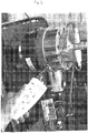
Figure 6 - shows another preferred embodiment of the load-indicating device of the present invention incorporating a rotary gauge; -
Figure 7 - shows a plurality of Hooke's law curves of different materials for the washer of the present invention; -
Figure 8 - shows another embodiment of the load-indicating device of the present invention incorporating an electrical circuit and visual indicating means; -
Figures 9a to 9d - show various views of another embodiment of the load-indicating device of the present invention; -
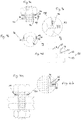
Figure 10a - shows a side cross-sectional view of a further embodiment of the load-indicating device of the present invention; -
Figure 10b - shows a magnified view of a portion of the device ofFigure 10a ; -
Figures 11a & 11b - show a further embodiment of a load-indicating device of the present invention incorporating a hand-held monitor for visual indication of correct load tensioning, illustrated in unconnected and connected states, respectively; -
Figure 12a - shows a side cross-sectional view of a probe contact according to a preferred embodiment; -
Figure 12b - shows a preferred embodiment illustrating a hand-held monitor connected to a pair of contacts as shown inFigure 12a ; -
Figure 12c - shows a magnified view of the pair of contacts as shown inFigure 12b ; -
Figure 13 - shows a hand-held monitor according to an alternative embodiment for automatically interrupting power to a power tool at a predetermined tension; -
Figure 14 - shows a further embodiment incorporating a computer to receive signals from a plurality of load-indicating devices; -
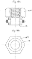
Figure 15a -- shows a side cross-sectional view of a further preferred embodiment of the load-indicating device integrated into a hexagonal nut; -
Figure 15b - shows a plan view of load-indicating device ofFigure 15a ; and -
Figure 16 - shows an arrangement of a load-indicating device with a hand-held monitor according to a particularly preferred embodiment incorporating a visual display in the form of a digital readout. - Referring to
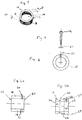
Figure 1 , there is a shown a particularly preferred embodiment of a load-indicatingdevice 10 according to the present invention. It is to be understood that the device as shown inFigure 1 is not drawn to scale and therefore the figure is intended for illustrative purposes only. - The
device 10 comprises a washer having atubular body 18, which defines a bore 13 extending therethrough. The device is ideally suited for use when joining two different mechanical assemblies together by way of nuts and bolts etc, and provides an accurate indication of the loading of an assembly when under a compressive load. Materials stretch or compress under load with stress being proportional to strain up to the materials' proof load (Hooke's Law) and if this can be measured it is the most reliable means of determining clamped loads in structural joints. - Under load, the force applied to the
body 18 of the washer will be a compressive force and the body will be deflected, i.e. compressed. Based on Hooke's law there is a linear relationship between the deflection (compression or extension) of the material of the washer and the force that is applied to it, up to a maximum proof load of the material, whereupon the linear relationship breaks down. Up to this maximum proof load, the material of the washer retains its elasticity, such that after the loading force responsible for compressing the material is removed, the body of the washer will return to its original un-compressed dimensions. - The
body 18 of the washer has aheight 12 and a thickness 16. In one embodiment, theheight 12 of the washer does not vary, but different thicknesses and materials of the washer can be used for different loading requirements. It should be appreciated that in an alternative embodiment, a washer with adifferent height 12 might be used. - The washer comprises at least one
hole 20 in the body of the washer for receiving at least oneprobe 14 to measure the deflection of the body under load.Figure 2 shows a side view of aprobe 14 that is located within thehole 20 of thebody 18 of the washer. In this example theprobe 14 is removably disposed within thehole 20 of the washer. In an alternative embodiment, the probe may be a non-removable component of the washer. -
Figure 3 shows a plan view of thebody 18 of the washer having ahole 20 for receiving theprobe 14 shown inFigure 2 . Thebody 18 of the washer is shown as having substantially circular dimensions in plan view, but a washer having a different geometry is also possible. -
Figure 4a shows a side cross-sectional view of the washer according to a preferred embodiment. The washer has afirst hole 20 and a second hole 21 in thebody 18. Thebody 18 has an upper load-bearing surface 42 and a lower load-bearing surface 42, which will deflect or compress thebody 18 of the washer under load. - The washer provides an accurate indication of the compressive force using only one hole. However, in an alternative embodiment a plurality of holes may be distributed around the circumference of the body, This advantageously provides an indication of an even distribution of the loading force around the washer which informs an operator that the mechanical joint is symmetrically loaded.
- The second hole 21 has a different (i.e. smaller) diameter to the first hole for indicating an over-load condition. That is, a
first probe 14 in thefirst hole 20 indicates when the force is at the predetermined tension or load, but a second probe in the second hole 21 is used to indicate when the force is in an over-loaded condition. - More specifically, if the
first probe 14 when inserted into thefirst hole 20 is free to rotate via manual manipulation, then an operator knows that the washer is under-load, namely that the predetermined tension has not yet been attained. Therefore, the operator knows that further tightening of the fastening components is required, until such time that the probe can no longer be rotated by finger pressure. In this case, the operator is then able to determine when the predetermined tension has been reached. By using a second hole 21 in thebody 18 of the washer, the operator can ascertain whether the joint has been over-loaded, as the second probe will be free to rotate unless the body of the washer has been compressed too far, indicating that the washer has been over-loaded. - The probe or probes can be colour coded for different predetermined loads, so that an operator can select and use the correct probe for the desired load.
-
Figure 4b shows an alternative embodiment in which aportion body 18 of the washer is reduced in diameter. This reduced diameter portion makes thebody 18 of the washer easier to deflect and therefore increases the sensitivity and range of the deflection (and compressive force) being determined. -
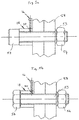
Figure 5a shows a load-indicatingdevice 10 in an example bolted joint using a cap screw & nut for tightening the mechanical assembly. Abolt 53 passes through the joint 58, together with the internal bore of the washer, and terminates in a cap screw 52. The head 54 of thebolt 53 can be turned to tighten the entire assembly. In use, thebolt 53 can be tightened by an operator until the load-indicatingdevice 10 indicates that the compressive force has reached the predetermined design load, whereupon the operator will no longer be able to rotate theprobe 14 within thehole 20 by manual manipulation, i.e. finger pressure. -
Figure 5b shows a load-indicatingdevice 10 in an alternative bolted joint using a bolt & nut for tightening the assembly. In exactly the same away as above, the operator can continue to tighten the bolt until such time as theprobe 14 no longer rotates within thehole 20, whereupon the compressive force has reached the predetermined design load. -
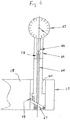
Figure 6 shows another embodiment of a load-indicating device according to the present invention, in which a clock gauge is used to indicate the load on the washer over the range of zero to proof load, Alever 67 disposed within a hole of the body of the washer, rotates around a fulcrum pin and reacts against acompression spring 69 when the washer deforms under load. This action forces arod 65 to move radially away from the centre of the washer (i.e. in a vertical direction inFigure 6 ). Therod 65 moves the probe 64 which in turn actuates thegauge 62, via aspring 66 and stem 64 mechanism. Thegauge 62 is calibrated to indicate the load on the washer. - Referring to
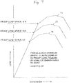
Figure 7 , there is shown a plurality of curves illustrating Hooke's law for different washer materials. The x-axis indicates the extension (or compression) of the material, while the y-axis indicates the loading force. Afirst curve 70 indicates a material with a proof load of grade 8.8,second curve 72 represents a material with a proof load of grade 10.9 and third curve 74 represents a material with a proof load ofgrade curves -
Figure 8 shows an alternative embodiment in which the load-indicating device forms part of an electrical circuit. In this arrangement theprobe 14 acts as an electrode having at least a portion of its length sheathed in an insulating material, such as plastic or rubber etc. Theprobe 14 is dimensioned such that a small air gap exists between the outer surface of the shank 81 of the probe and the interior walls of thehole 20. The walls of thehole 20 serve as the other electrode in the electrical circuit. The insulation is arranged to deflect when the body of the washer is under load, such that the shank 81 of theprobe 14 comes into physical and electrical contact with the walls of thehole 20. Alight source 82, which can be a filament bulb or LED etc. forms part of the electrical circuit. Therefore, when the washer is loaded to the predetermined tension, the probe and the hole are electrically connected enabling thelight source 82 to be illuminated. As a result, the operator can then be made aware of the correct loading by way of a visual indication, namely the illumination of thelight source 82. A cell or battery 84 provides power for the electrical circuit. - It is to be appreciated that in alternative embodiments, the interior of the hole may be insulated instead of the probe, and therefore either arrangement may form part of the present invention.
- In
Figures 9a-d there is shown another electrical implementation of the load-indicating device of the present invention. Referring toFigure 9a , there is shown a washer under load with a probe orRota 92 inserted into a hole of thebody 18 of the washer. Thebody 18 also comprises anadjustment control pin 96, which is connected to an upper load-bearing surface of the washer. A clamping screw 98 (shown inFigures 9b & 9c ) is used to adjust the position of the control pin. Arota retention pin 94 retains theprobe 92 in position within the hole of thebody 18 of the washer. -
Figure 9d shows a magnified view of a portion of the washer, showing the probe and pins in more detail. Theadjustment control pin 96 extends downwardly from the upper load-bearing surface 42. An air gap 97 is present between the tip of thecontrol pin 96 and a first layer of electrical insulation 93 covering at least a portion of the length of theprobe 92. Under load, the upper load bearing surface will be deflected due to the compressive tightening force, allowing the tip of thepin 96 to be forced down into the air gap 97 and through the insulating material 93 to make electrical contact with the shank of theprobe 92. Therefore by carefully selecting the size of the air gap and the dimensions of the probe and hole etc. the electrical circuit can be configured to illuminate a LED etc. when the predetermined loading force has been reached. -
Figures 10a and 10b show a further electrical implementation of the load-indicating device of the present invention. The structure and function of this embodiment is similar to that ofFigures 9a-d . - Referring to
Figure 11a , there is shown another preferred embodiment of the load-indicating device according to the present invention. In this embodiment, the device comprises a hand-heldmonitor 110 which is intended to be portable and used remotely from the device. As shown, the device comprises twoprobes 14, one for indicating correct loading (i.e. at the predetermined tension) and another for indicating an over-load condition. Theprobes 14 are protected by respectiveprotective caps 117 to prevent damage to the ends of the probes when the device is not in use. - The hand-held
monitor 110 may be used to indicate the load on any grade or size of bolt or stud etc. and therefore this embodiment is inherently scalable. Three LEDs are provided in themonitor 110, each ideally being of a different colour. For example in the embodiment ofFigure 11a , ared LED 120 is provided to indicate an under-loading condition, in which further tightening of the fastening components would be required. Agreen LED 122 is provided to indicate that the correct loading has been attained, namely that the washer has reached the predetermined tension; while ayellow LED 124 is provided to indicate that an over-loaded condition has occurred, requiring the operator to loosen the fastening components due to over tensioning of the components. Of course, any arrangement of LEDs and colours thereof may be used to indicate the various loading conditions, and indeed other display devices (e.g. LED matrices, LCDs etc.) may alternatively or additionally be used to convey loading information to an operator. Moreover, an audible indicator may also be used to provide a sound signal or tone to the operator, which could be modulated depending on the loading of the washer. - As shown in
Figures 11a & 11b , the hand-heldmonitor 110 is connected to theprobes 14 viaconnectors connectors probes 14 once theprotective caps Figure 11b . -
Figures 12a-12c show theconnectors Figure 12a , theconnector 112 comprises magnets 121 that are magnetically attracted to the body of the washer to enable thecontact 112 to remain in place after it has been pushed onto the end of theprobe 14. - In another embodiment as shown in
Figure 13 , the load-indicating device can be configured to automatically interrupt the power to apower tool 130 that is being used to tighten the fastening components. In this example, themonitor 110 comprises an output port operable to send an interrupt signal along connection 134 to a solenoid valve or rely 132 when the predetermined tension has been reached. Thepower tool 130 may be purely electrical or may be an air tool, which operates via compressed air, or may be both. Therefore, thesolenoid valve 132 may also, or alternatively, be used to control the air flow to thepower tool 130 while tightening the fastening components.Probe 136 is operable to send an electrical signal indicative of the load on the washer along lead 138 to themonitor 110. Once the correct predetermined tension has been reached, an output signal is sent to thesolenoid valve 132 to interrupt the power tool, thereby preventing an over-load condition from arising, - Instead of a hand-held monitor, the load-indicating device may be connected to a computer for monitoring and displaying the load on the washer. As shown in
Figure 14 ,computer 140 comprisesprocessors 142 and 144 that are arranged to receive data from respective load-indicating devices. This implementation is particularly advantageous for use in environments that are potentially hazardous or are otherwise difficult to operate in, for example marine environments or nuclear reactor cores etc. Wired connections or fibre optic cables may be permanently connected to the probes of all of the devices for real-time monitoring of the respective loading conditions. - Although the washer of the present device is ideally suited for deployment between two fastening components, it is envisaged that the load-indicating device may alternatively be integrated into one of more of the fastening components themselves. Therefore, as shown in the example of
Figures 15a & 15b , the 'washer' has been integrated into the body of a hexagonal nut, with the interior bore of the washer being threaded. Of course, any form of fastening component may be used and therefore the present device may be integrated into any nut or bolt type, or joint assembly etc., depending on the particular requirements and application. -
Figure 16 shows a further embodiment of the hand-held monitor implementation, in which an output of themonitor 110 can be connected to a digital readout display 160 or similar, to provide a more quantitative measure of the loading force on the washer. - As will be appreciated from the foregoing embodiments, the present invention is able to provide a simple, easy to fit, and cost-effective means of indicating accurate loading of a mechanical assembly. Therefore, although the load-indicating device is ideally suited for ensuring a reliable and consistent tensioning of fastening components, it will be recognised that one or more of the principles of the invention may extend to other fastening or securing applications, whereby it is required to tension or load a mechanical connection to an accurate predetermined value or tolerance.
- The above embodiments are described by way of example only. Many variations are possible without departing from the invention.
Claims (15)
- A load-indicating device (10), comprising:a washer having a tubular body (18) defining a bore (13) extending therethrough, the body (18) comprising at least one radial hole (20) extending at least partially through the body (18); anda probe (14) configured to be disposed within the at least one radial hole (20) and operable to provide an indication of the compression on the washer, such that, in use, the washer deflects to compress the hole (20) against the probe (14) when the load on the washer reaches a predetermined tension,wherein the probe (14) is arranged to be rotatable within the hole (20) until the load on the washer reaches the predetermined tension.
- The device of Claim 1, wherein the deflection of the washer is configured to bring at least one side wall of the hole (20) into contact with an outer surface of the probe (14).
- The device of Claim 1 or Claim 2, wherein the probe (14) is an elongate pin.
- The device of any preceding claim, wherein a portion (46,48) of the body (18) of the washer is reduced in diameter.
- The device of any preceding claim, wherein the body (18) comprises upper and lower load-bearing surfaces (42,44).
- The device of any preceding claim, wherein the probe (14) is either mechanically or electrically connected to a visual display device to provide a visual indication of the loading on the washer.
- The device of Claim 6, wherein the visual display device is a rotary gauge operably connected to the probe (14) via a mechanical lever.
- The device of any preceding claim, wherein the body (18) and the probe (14) form part of an electrical circuit which is configured to permit the flow of current when the load on the washer reaches the predetermined tension.
- The device of Claim 8, wherein the probe is in the form of an electrode.
- The device of Claim 8 or Claim 9, wherein at least a portion of the probe (14) is electrically insulated.
- The device of any of Claims 8 to 10, wherein the electrical circuit comprises at least one light source (82) that is operable to illuminate in response to the flow of current.
- The device of any of Claims 8 to 11, wherein the electrical circuit further comprises a plurality of light sources (120,122,124) operable to indicate at least one of: an under-loading condition, an over-loading condition and a design loading condition.
- The device of Claim 12, wherein the plurality of light sources (120,122,124) are disposed in a hand-held device (110) configured to be used remotely from the load-indicating device (10).
- The device of any preceding claim, wherein the body (18) further comprises a second radial hole (21) extending at least partially through the body (18) and configured to receive a second probe, wherein the first and second radial holes (20, 21) are non-contiguous.
- The device of Claim 14, wherein the second probe is operable to provide an indication of an over-loading condition on the washer.
Applications Claiming Priority (2)
| Application Number | Priority Date | Filing Date | Title |
|---|---|---|---|
| GBGB1115040.6A GB201115040D0 (en) | 2011-08-31 | 2011-08-31 | Load indicating washer |
| PCT/GB2012/052114 WO2013030567A1 (en) | 2011-08-31 | 2012-08-29 | A load-indicating device |
Publications (2)
| Publication Number | Publication Date |
|---|---|
| EP2751537A1 EP2751537A1 (en) | 2014-07-09 |
| EP2751537B1 true EP2751537B1 (en) | 2019-10-02 |
Family
ID=44838985
Family Applications (1)
| Application Number | Title | Priority Date | Filing Date |
|---|---|---|---|
| EP12801622.7A Active EP2751537B1 (en) | 2011-08-31 | 2012-08-29 | A load-indicating device |
Country Status (10)
| Country | Link |
|---|---|
| US (1) | US9612172B2 (en) |
| EP (1) | EP2751537B1 (en) |
| JP (1) | JP2014525578A (en) |
| KR (1) | KR102043812B1 (en) |
| CN (1) | CN103975228B (en) |
| AU (1) | AU2012300631B2 (en) |
| BR (1) | BR112014004419B1 (en) |
| CA (1) | CA2881624C (en) |
| GB (1) | GB201115040D0 (en) |
| WO (1) | WO2013030567A1 (en) |
Families Citing this family (7)
| Publication number | Priority date | Publication date | Assignee | Title |
|---|---|---|---|---|
| GB201300093D0 (en) | 2013-01-04 | 2013-02-20 | Phipps Maria J | Load indicating nut/washer |
| US10238764B2 (en) | 2014-08-19 | 2019-03-26 | Vapium Inc. | Aromatherapy vaporization device |
| US9677592B2 (en) * | 2014-11-03 | 2017-06-13 | The Boeing Company | Witness enabled fasteners and related systems and methods |
| RU168232U1 (en) * | 2016-06-24 | 2017-01-24 | Федеральное государственное бюджетное образовательное учреждение высшего образования "Псковский государственный университет" | ALARM DEVICE FOR RELAXING TIGHTENING OF THREADED CONNECTOR CONNECTION |
| CN108071649A (en) * | 2016-11-16 | 2018-05-25 | 孙愉后 | Fastener |
| BE1025510B1 (en) * | 2018-02-06 | 2019-03-21 | Zensor Nv | Washer unit and voltage detection system for a confirmed coupling |
| RU206443U1 (en) * | 2021-05-04 | 2021-09-13 | Федеральное государственное бюджетное образовательное учреждение высшего образования "Сибирский государственный университет науки и технологий имени академика М.Ф. Решетнева" (СибГУ им. М.Ф. Решетнева) | TIGHTENED BOLT CONNECTION STAND |
Family Cites Families (21)
| Publication number | Priority date | Publication date | Assignee | Title |
|---|---|---|---|---|
| US3306154A (en) * | 1965-10-23 | 1967-02-28 | Mcculloch Corp | Compressive load limit indicators |
| US4483648A (en) * | 1979-07-09 | 1984-11-20 | Trungold Emanuel H | Bolt tension indicating means |
| JPS6053828A (en) * | 1983-09-05 | 1985-03-27 | Idemitsu Petrochem Co Ltd | Method for measuring tightening state of bolt shaft |
| US4630490A (en) * | 1985-07-12 | 1986-12-23 | Carron & Company | Compression strain gauge transducer assembly |
| GB2184509B (en) * | 1985-11-13 | 1988-12-14 | Exotech Ltd | Fastener, power tool for use with same and method tightening the fastener |
| US5291789A (en) * | 1987-11-10 | 1994-03-08 | Rotabolt Limited | Load indicating |
| GB8726339D0 (en) * | 1987-11-10 | 1987-12-16 | Walton B | Fastener |
| US4823606A (en) * | 1988-06-23 | 1989-04-25 | Carron & Company | Diaphragm transducer for sensing loading |
| US5102273A (en) * | 1991-02-25 | 1992-04-07 | Allied-Signal Inc. | Visually indicated preloaded bolt |
| GB9207880D0 (en) * | 1992-04-10 | 1992-05-27 | Ceney Stanley | Load indicating fasteners |
| GB2306601A (en) | 1995-10-24 | 1997-05-07 | Exotech Ltd | Tightness indicator for threaded fasteners |
| NO302715B1 (en) * | 1996-06-19 | 1998-04-14 | Scan Mag Sense As | Device for measuring compressive forces |
| US5668323A (en) * | 1996-07-12 | 1997-09-16 | Waxman; Cory S. | Method and apparatus for indicating a load |
| US6204771B1 (en) * | 1997-08-19 | 2001-03-20 | Ronald C. Clarke | Load indicating fastener systems method and apparatus |
| AU743407B2 (en) * | 1997-08-19 | 2002-01-24 | Clarke, Philomena J. | Load indicating fastener systems method and apparatus |
| US7698949B2 (en) | 2005-09-09 | 2010-04-20 | The Boeing Company | Active washers for monitoring bolted joints |
| US7412898B1 (en) * | 2006-07-28 | 2008-08-19 | Disney Enterprises, Inc. | Load sensing system including RFID tagged fasteners |
| US8024979B2 (en) * | 2006-08-24 | 2011-09-27 | Clarke Ronald C | Indicating fastener loading |
| JP5061387B2 (en) * | 2007-08-28 | 2012-10-31 | 国立大学法人京都大学 | Electrode probe and capacitance load cell using the same |
| GB201300093D0 (en) * | 2013-01-04 | 2013-02-20 | Phipps Maria J | Load indicating nut/washer |
| TWI518253B (en) * | 2013-03-12 | 2016-01-21 | Kabo Tool Co | Can feel the tension of the screw pieces |
-
2011
- 2011-08-31 GB GBGB1115040.6A patent/GB201115040D0/en not_active Ceased
-
2012
- 2012-08-29 BR BR112014004419-8A patent/BR112014004419B1/en active IP Right Grant
- 2012-08-29 EP EP12801622.7A patent/EP2751537B1/en active Active
- 2012-08-29 KR KR1020147007864A patent/KR102043812B1/en active IP Right Grant
- 2012-08-29 WO PCT/GB2012/052114 patent/WO2013030567A1/en active Application Filing
- 2012-08-29 CN CN201280045628.2A patent/CN103975228B/en not_active Expired - Fee Related
- 2012-08-29 JP JP2014527732A patent/JP2014525578A/en active Pending
- 2012-08-29 CA CA2881624A patent/CA2881624C/en active Active
- 2012-08-29 AU AU2012300631A patent/AU2012300631B2/en not_active Ceased
- 2012-08-29 US US14/241,195 patent/US9612172B2/en active Active
Non-Patent Citations (1)
| Title |
|---|
| None * |
Also Published As
| Publication number | Publication date |
|---|---|
| JP2014525578A (en) | 2014-09-29 |
| EP2751537A1 (en) | 2014-07-09 |
| CA2881624A1 (en) | 2013-03-07 |
| KR20140077890A (en) | 2014-06-24 |
| AU2012300631B2 (en) | 2015-11-26 |
| GB201115040D0 (en) | 2011-10-12 |
| BR112014004419A2 (en) | 2017-03-21 |
| WO2013030567A1 (en) | 2013-03-07 |
| US20140283624A1 (en) | 2014-09-25 |
| KR102043812B1 (en) | 2019-11-12 |
| CN103975228B (en) | 2016-11-02 |
| US9612172B2 (en) | 2017-04-04 |
| CN103975228A (en) | 2014-08-06 |
| AU2012300631A8 (en) | 2015-10-29 |
| CA2881624C (en) | 2020-01-21 |
| AU2012300631A1 (en) | 2014-03-13 |
| BR112014004419B1 (en) | 2020-10-20 |
Similar Documents
| Publication | Publication Date | Title |
|---|---|---|
| EP2751537B1 (en) | A load-indicating device | |
| US9933004B2 (en) | Load-indicating device | |
| US9248532B2 (en) | Screw tensioning device | |
| US7520174B2 (en) | Method and apparatus for indicating a load | |
| CN104713674A (en) | Device for detecting axial tightening force of hexagonal head bolts | |
| US20130199307A1 (en) | Assembly, intercalated between a torque tool and a fastening element, for measuring torques and tightening angles | |
| JP2017067747A (en) | Method for determining fastening axial force of tapping screw and display device of the same | |
| CA2260040C (en) | Method and apparatus for indicating a load | |
| US20170131171A1 (en) | Tension and Torque Calibration Apparatus | |
| EP2436936A1 (en) | Bolt preloading check system | |
| WO2019077314A1 (en) | Load indicating fastener | |
| JPH0213957Y2 (en) | ||
| US7156595B2 (en) | Load indicating fastener insert | |
| WO2024023096A1 (en) | Preload verification for critical fasteners | |
| EP3556940A1 (en) | Method of permanent adjustment of spring elements tension for use under dynamic load | |
| GB2601330A (en) | A load-indicating device | |
| CN115419646A (en) | Multifunctional fastening characteristic test bolt | |
| GB2469930A (en) | Bolt tension controller | |
| EP2436937A1 (en) | Bolt tension controller | |
| CN114962412A (en) | Bolt for measuring pretightening force and machining method thereof | |
| KR20030073636A (en) | Bolt grip gage |
Legal Events
| Date | Code | Title | Description |
|---|---|---|---|
| PUAI | Public reference made under article 153(3) epc to a published international application that has entered the european phase |
Free format text: ORIGINAL CODE: 0009012 |
|
| 17P | Request for examination filed |
Effective date: 20140227 |
|
| AK | Designated contracting states |
Kind code of ref document: A1 Designated state(s): AL AT BE BG CH CY CZ DE DK EE ES FI FR GB GR HR HU IE IS IT LI LT LU LV MC MK MT NL NO PL PT RO RS SE SI SK SM TR |
|
| DAX | Request for extension of the european patent (deleted) | ||
| RAP1 | Party data changed (applicant data changed or rights of an application transferred) |
Owner name: TENSCON LIMITED |
|
| STAA | Information on the status of an ep patent application or granted ep patent |
Free format text: STATUS: EXAMINATION IS IN PROGRESS |
|
| 17Q | First examination report despatched |
Effective date: 20171219 |
|
| GRAP | Despatch of communication of intention to grant a patent |
Free format text: ORIGINAL CODE: EPIDOSNIGR1 |
|
| STAA | Information on the status of an ep patent application or granted ep patent |
Free format text: STATUS: GRANT OF PATENT IS INTENDED |
|
| INTG | Intention to grant announced |
Effective date: 20190711 |
|
| GRAS | Grant fee paid |
Free format text: ORIGINAL CODE: EPIDOSNIGR3 |
|
| GRAA | (expected) grant |
Free format text: ORIGINAL CODE: 0009210 |
|
| STAA | Information on the status of an ep patent application or granted ep patent |
Free format text: STATUS: THE PATENT HAS BEEN GRANTED |
|
| AK | Designated contracting states |
Kind code of ref document: B1 Designated state(s): AL AT BE BG CH CY CZ DE DK EE ES FI FR GB GR HR HU IE IS IT LI LT LU LV MC MK MT NL NO PL PT RO RS SE SI SK SM TR |
|
| REG | Reference to a national code |
Ref country code: GB Ref legal event code: FG4D |
|
| REG | Reference to a national code |
Ref country code: CH Ref legal event code: EP Ref country code: AT Ref legal event code: REF Ref document number: 1186708 Country of ref document: AT Kind code of ref document: T Effective date: 20191015 |
|
| REG | Reference to a national code |
Ref country code: DE Ref legal event code: R096 Ref document number: 602012064566 Country of ref document: DE |
|
| REG | Reference to a national code |
Ref country code: IE Ref legal event code: FG4D |
|
| REG | Reference to a national code |
Ref country code: NL Ref legal event code: MP Effective date: 20191002 |
|
| REG | Reference to a national code |
Ref country code: LT Ref legal event code: MG4D |
|
| REG | Reference to a national code |
Ref country code: AT Ref legal event code: MK05 Ref document number: 1186708 Country of ref document: AT Kind code of ref document: T Effective date: 20191002 |
|
| PG25 | Lapsed in a contracting state [announced via postgrant information from national office to epo] |
Ref country code: ES Free format text: LAPSE BECAUSE OF FAILURE TO SUBMIT A TRANSLATION OF THE DESCRIPTION OR TO PAY THE FEE WITHIN THE PRESCRIBED TIME-LIMIT Effective date: 20191002 Ref country code: LV Free format text: LAPSE BECAUSE OF FAILURE TO SUBMIT A TRANSLATION OF THE DESCRIPTION OR TO PAY THE FEE WITHIN THE PRESCRIBED TIME-LIMIT Effective date: 20191002 Ref country code: SE Free format text: LAPSE BECAUSE OF FAILURE TO SUBMIT A TRANSLATION OF THE DESCRIPTION OR TO PAY THE FEE WITHIN THE PRESCRIBED TIME-LIMIT Effective date: 20191002 Ref country code: NL Free format text: LAPSE BECAUSE OF FAILURE TO SUBMIT A TRANSLATION OF THE DESCRIPTION OR TO PAY THE FEE WITHIN THE PRESCRIBED TIME-LIMIT Effective date: 20191002 Ref country code: AT Free format text: LAPSE BECAUSE OF FAILURE TO SUBMIT A TRANSLATION OF THE DESCRIPTION OR TO PAY THE FEE WITHIN THE PRESCRIBED TIME-LIMIT Effective date: 20191002 Ref country code: FI Free format text: LAPSE BECAUSE OF FAILURE TO SUBMIT A TRANSLATION OF THE DESCRIPTION OR TO PAY THE FEE WITHIN THE PRESCRIBED TIME-LIMIT Effective date: 20191002 Ref country code: BG Free format text: LAPSE BECAUSE OF FAILURE TO SUBMIT A TRANSLATION OF THE DESCRIPTION OR TO PAY THE FEE WITHIN THE PRESCRIBED TIME-LIMIT Effective date: 20200102 Ref country code: PT Free format text: LAPSE BECAUSE OF FAILURE TO SUBMIT A TRANSLATION OF THE DESCRIPTION OR TO PAY THE FEE WITHIN THE PRESCRIBED TIME-LIMIT Effective date: 20200203 Ref country code: LT Free format text: LAPSE BECAUSE OF FAILURE TO SUBMIT A TRANSLATION OF THE DESCRIPTION OR TO PAY THE FEE WITHIN THE PRESCRIBED TIME-LIMIT Effective date: 20191002 Ref country code: NO Free format text: LAPSE BECAUSE OF FAILURE TO SUBMIT A TRANSLATION OF THE DESCRIPTION OR TO PAY THE FEE WITHIN THE PRESCRIBED TIME-LIMIT Effective date: 20200102 Ref country code: PL Free format text: LAPSE BECAUSE OF FAILURE TO SUBMIT A TRANSLATION OF THE DESCRIPTION OR TO PAY THE FEE WITHIN THE PRESCRIBED TIME-LIMIT Effective date: 20191002 Ref country code: GR Free format text: LAPSE BECAUSE OF FAILURE TO SUBMIT A TRANSLATION OF THE DESCRIPTION OR TO PAY THE FEE WITHIN THE PRESCRIBED TIME-LIMIT Effective date: 20200103 |
|
| PG25 | Lapsed in a contracting state [announced via postgrant information from national office to epo] |
Ref country code: RS Free format text: LAPSE BECAUSE OF FAILURE TO SUBMIT A TRANSLATION OF THE DESCRIPTION OR TO PAY THE FEE WITHIN THE PRESCRIBED TIME-LIMIT Effective date: 20191002 Ref country code: HR Free format text: LAPSE BECAUSE OF FAILURE TO SUBMIT A TRANSLATION OF THE DESCRIPTION OR TO PAY THE FEE WITHIN THE PRESCRIBED TIME-LIMIT Effective date: 20191002 Ref country code: CZ Free format text: LAPSE BECAUSE OF FAILURE TO SUBMIT A TRANSLATION OF THE DESCRIPTION OR TO PAY THE FEE WITHIN THE PRESCRIBED TIME-LIMIT Effective date: 20191002 Ref country code: IS Free format text: LAPSE BECAUSE OF FAILURE TO SUBMIT A TRANSLATION OF THE DESCRIPTION OR TO PAY THE FEE WITHIN THE PRESCRIBED TIME-LIMIT Effective date: 20200224 |
|
| PG25 | Lapsed in a contracting state [announced via postgrant information from national office to epo] |
Ref country code: AL Free format text: LAPSE BECAUSE OF FAILURE TO SUBMIT A TRANSLATION OF THE DESCRIPTION OR TO PAY THE FEE WITHIN THE PRESCRIBED TIME-LIMIT Effective date: 20191002 |
|
| REG | Reference to a national code |
Ref country code: DE Ref legal event code: R097 Ref document number: 602012064566 Country of ref document: DE |
|
| PG2D | Information on lapse in contracting state deleted |
Ref country code: IS |
|
| PG25 | Lapsed in a contracting state [announced via postgrant information from national office to epo] |
Ref country code: RO Free format text: LAPSE BECAUSE OF FAILURE TO SUBMIT A TRANSLATION OF THE DESCRIPTION OR TO PAY THE FEE WITHIN THE PRESCRIBED TIME-LIMIT Effective date: 20191002 Ref country code: EE Free format text: LAPSE BECAUSE OF FAILURE TO SUBMIT A TRANSLATION OF THE DESCRIPTION OR TO PAY THE FEE WITHIN THE PRESCRIBED TIME-LIMIT Effective date: 20191002 Ref country code: DK Free format text: LAPSE BECAUSE OF FAILURE TO SUBMIT A TRANSLATION OF THE DESCRIPTION OR TO PAY THE FEE WITHIN THE PRESCRIBED TIME-LIMIT Effective date: 20191002 Ref country code: IS Free format text: LAPSE BECAUSE OF FAILURE TO SUBMIT A TRANSLATION OF THE DESCRIPTION OR TO PAY THE FEE WITHIN THE PRESCRIBED TIME-LIMIT Effective date: 20200202 |
|
| PLBE | No opposition filed within time limit |
Free format text: ORIGINAL CODE: 0009261 |
|
| STAA | Information on the status of an ep patent application or granted ep patent |
Free format text: STATUS: NO OPPOSITION FILED WITHIN TIME LIMIT |
|
| PG25 | Lapsed in a contracting state [announced via postgrant information from national office to epo] |
Ref country code: SM Free format text: LAPSE BECAUSE OF FAILURE TO SUBMIT A TRANSLATION OF THE DESCRIPTION OR TO PAY THE FEE WITHIN THE PRESCRIBED TIME-LIMIT Effective date: 20191002 Ref country code: SK Free format text: LAPSE BECAUSE OF FAILURE TO SUBMIT A TRANSLATION OF THE DESCRIPTION OR TO PAY THE FEE WITHIN THE PRESCRIBED TIME-LIMIT Effective date: 20191002 Ref country code: IT Free format text: LAPSE BECAUSE OF FAILURE TO SUBMIT A TRANSLATION OF THE DESCRIPTION OR TO PAY THE FEE WITHIN THE PRESCRIBED TIME-LIMIT Effective date: 20191002 |
|
| 26N | No opposition filed |
Effective date: 20200703 |
|
| PG25 | Lapsed in a contracting state [announced via postgrant information from national office to epo] |
Ref country code: SI Free format text: LAPSE BECAUSE OF FAILURE TO SUBMIT A TRANSLATION OF THE DESCRIPTION OR TO PAY THE FEE WITHIN THE PRESCRIBED TIME-LIMIT Effective date: 20191002 |
|
| REG | Reference to a national code |
Ref country code: DE Ref legal event code: R119 Ref document number: 602012064566 Country of ref document: DE |
|
| PG25 | Lapsed in a contracting state [announced via postgrant information from national office to epo] |
Ref country code: MC Free format text: LAPSE BECAUSE OF FAILURE TO SUBMIT A TRANSLATION OF THE DESCRIPTION OR TO PAY THE FEE WITHIN THE PRESCRIBED TIME-LIMIT Effective date: 20191002 |
|
| REG | Reference to a national code |
Ref country code: CH Ref legal event code: PL |
|
| PG25 | Lapsed in a contracting state [announced via postgrant information from national office to epo] |
Ref country code: LI Free format text: LAPSE BECAUSE OF NON-PAYMENT OF DUE FEES Effective date: 20200831 Ref country code: CH Free format text: LAPSE BECAUSE OF NON-PAYMENT OF DUE FEES Effective date: 20200831 Ref country code: LU Free format text: LAPSE BECAUSE OF NON-PAYMENT OF DUE FEES Effective date: 20200829 |
|
| REG | Reference to a national code |
Ref country code: BE Ref legal event code: MM Effective date: 20200831 |
|
| PG25 | Lapsed in a contracting state [announced via postgrant information from national office to epo] |
Ref country code: DE Free format text: LAPSE BECAUSE OF NON-PAYMENT OF DUE FEES Effective date: 20210302 Ref country code: FR Free format text: LAPSE BECAUSE OF NON-PAYMENT OF DUE FEES Effective date: 20200831 |
|
| PG25 | Lapsed in a contracting state [announced via postgrant information from national office to epo] |
Ref country code: BE Free format text: LAPSE BECAUSE OF NON-PAYMENT OF DUE FEES Effective date: 20200831 Ref country code: IE Free format text: LAPSE BECAUSE OF NON-PAYMENT OF DUE FEES Effective date: 20200829 |
|
| PG25 | Lapsed in a contracting state [announced via postgrant information from national office to epo] |
Ref country code: TR Free format text: LAPSE BECAUSE OF FAILURE TO SUBMIT A TRANSLATION OF THE DESCRIPTION OR TO PAY THE FEE WITHIN THE PRESCRIBED TIME-LIMIT Effective date: 20191002 Ref country code: MT Free format text: LAPSE BECAUSE OF FAILURE TO SUBMIT A TRANSLATION OF THE DESCRIPTION OR TO PAY THE FEE WITHIN THE PRESCRIBED TIME-LIMIT Effective date: 20191002 Ref country code: CY Free format text: LAPSE BECAUSE OF FAILURE TO SUBMIT A TRANSLATION OF THE DESCRIPTION OR TO PAY THE FEE WITHIN THE PRESCRIBED TIME-LIMIT Effective date: 20191002 |
|
| PG25 | Lapsed in a contracting state [announced via postgrant information from national office to epo] |
Ref country code: MK Free format text: LAPSE BECAUSE OF FAILURE TO SUBMIT A TRANSLATION OF THE DESCRIPTION OR TO PAY THE FEE WITHIN THE PRESCRIBED TIME-LIMIT Effective date: 20191002 |
|
| PGFP | Annual fee paid to national office [announced via postgrant information from national office to epo] |
Ref country code: GB Payment date: 20220825 Year of fee payment: 11 |
|
| GBPC | Gb: european patent ceased through non-payment of renewal fee |
Effective date: 20230829 |