EP2749942B1 - Projector and method for controlling Projector - Google Patents
Projector and method for controlling Projector Download PDFInfo
- Publication number
- EP2749942B1 EP2749942B1 EP13197527.8A EP13197527A EP2749942B1 EP 2749942 B1 EP2749942 B1 EP 2749942B1 EP 13197527 A EP13197527 A EP 13197527A EP 2749942 B1 EP2749942 B1 EP 2749942B1
- Authority
- EP
- European Patent Office
- Prior art keywords
- electric power
- level
- discharge tube
- power saving
- projector
- Prior art date
- Legal status (The legal status is an assumption and is not a legal conclusion. Google has not performed a legal analysis and makes no representation as to the accuracy of the status listed.)
- Active
Links
- 238000000034 method Methods 0.000 title claims description 35
- 230000009471 action Effects 0.000 claims description 164
- 230000008859 change Effects 0.000 claims description 24
- 230000008569 process Effects 0.000 claims description 24
- 230000004044 response Effects 0.000 claims description 3
- 230000006870 function Effects 0.000 description 20
- 238000001514 detection method Methods 0.000 description 16
- 239000004973 liquid crystal related substance Substances 0.000 description 8
- 230000007246 mechanism Effects 0.000 description 5
- 230000004907 flux Effects 0.000 description 3
- 230000003287 optical effect Effects 0.000 description 3
- 230000015556 catabolic process Effects 0.000 description 2
- 239000003086 colorant Substances 0.000 description 2
- 238000006731 degradation reaction Methods 0.000 description 2
- 238000010586 diagram Methods 0.000 description 2
- 239000011159 matrix material Substances 0.000 description 2
- QSHDDOUJBYECFT-UHFFFAOYSA-N mercury Chemical compound [Hg] QSHDDOUJBYECFT-UHFFFAOYSA-N 0.000 description 2
- 229910052753 mercury Inorganic materials 0.000 description 2
- 230000007704 transition Effects 0.000 description 2
- 230000008901 benefit Effects 0.000 description 1
- 238000002834 transmittance Methods 0.000 description 1
- 229910052724 xenon Inorganic materials 0.000 description 1
- FHNFHKCVQCLJFQ-UHFFFAOYSA-N xenon atom Chemical compound [Xe] FHNFHKCVQCLJFQ-UHFFFAOYSA-N 0.000 description 1
Images


Classifications
-
- G—PHYSICS
- G03—PHOTOGRAPHY; CINEMATOGRAPHY; ANALOGOUS TECHNIQUES USING WAVES OTHER THAN OPTICAL WAVES; ELECTROGRAPHY; HOLOGRAPHY
- G03B—APPARATUS OR ARRANGEMENTS FOR TAKING PHOTOGRAPHS OR FOR PROJECTING OR VIEWING THEM; APPARATUS OR ARRANGEMENTS EMPLOYING ANALOGOUS TECHNIQUES USING WAVES OTHER THAN OPTICAL WAVES; ACCESSORIES THEREFOR
- G03B21/00—Projectors or projection-type viewers; Accessories therefor
- G03B21/14—Details
- G03B21/20—Lamp housings
- G03B21/2053—Intensity control of illuminating light
-
- G—PHYSICS
- G03—PHOTOGRAPHY; CINEMATOGRAPHY; ANALOGOUS TECHNIQUES USING WAVES OTHER THAN OPTICAL WAVES; ELECTROGRAPHY; HOLOGRAPHY
- G03B—APPARATUS OR ARRANGEMENTS FOR TAKING PHOTOGRAPHS OR FOR PROJECTING OR VIEWING THEM; APPARATUS OR ARRANGEMENTS EMPLOYING ANALOGOUS TECHNIQUES USING WAVES OTHER THAN OPTICAL WAVES; ACCESSORIES THEREFOR
- G03B21/00—Projectors or projection-type viewers; Accessories therefor
- G03B21/14—Details
- G03B21/20—Lamp housings
- G03B21/2006—Lamp housings characterised by the light source
- G03B21/2026—Gas discharge type light sources, e.g. arcs
-
- G—PHYSICS
- G06—COMPUTING; CALCULATING OR COUNTING
- G06F—ELECTRIC DIGITAL DATA PROCESSING
- G06F1/00—Details not covered by groups G06F3/00 - G06F13/00 and G06F21/00
- G06F1/26—Power supply means, e.g. regulation thereof
- G06F1/32—Means for saving power
- G06F1/3203—Power management, i.e. event-based initiation of a power-saving mode
-
- H—ELECTRICITY
- H04—ELECTRIC COMMUNICATION TECHNIQUE
- H04N—PICTORIAL COMMUNICATION, e.g. TELEVISION
- H04N9/00—Details of colour television systems
- H04N9/12—Picture reproducers
- H04N9/31—Projection devices for colour picture display, e.g. using electronic spatial light modulators [ESLM]
- H04N9/3141—Constructional details thereof
- H04N9/315—Modulator illumination systems
- H04N9/3155—Modulator illumination systems for controlling the light source
-
- H—ELECTRICITY
- H05—ELECTRIC TECHNIQUES NOT OTHERWISE PROVIDED FOR
- H05B—ELECTRIC HEATING; ELECTRIC LIGHT SOURCES NOT OTHERWISE PROVIDED FOR; CIRCUIT ARRANGEMENTS FOR ELECTRIC LIGHT SOURCES, IN GENERAL
- H05B41/00—Circuit arrangements or apparatus for igniting or operating discharge lamps
- H05B41/14—Circuit arrangements
- H05B41/26—Circuit arrangements in which the lamp is fed by power derived from dc by means of a converter, e.g. by high-voltage dc
- H05B41/28—Circuit arrangements in which the lamp is fed by power derived from dc by means of a converter, e.g. by high-voltage dc using static converters
- H05B41/288—Circuit arrangements in which the lamp is fed by power derived from dc by means of a converter, e.g. by high-voltage dc using static converters with semiconductor devices and specially adapted for lamps without preheating electrodes, e.g. for high-intensity discharge lamps, high-pressure mercury or sodium lamps or low-pressure sodium lamps
Definitions
- the present invention relates to a projector and a method for controlling the projector.
- JP-A-2012-108216 As a light source of a projector of related art, there is a known light source using a discharge tube, such as a high-pressure mercury lamp. There is a known projector of this type in which electric power supplied to the discharge tube is reduced for power saving (see JP-A-2012-108216 , for example). For example, the projector described in JP-A-2012-108216 attempts to reduce the amount of power consumption during projection without degradation in image quality by reducing electric power supplied to the discharge tube based, for example, on illuminance in the surrounding environment.
- electric power supply to the discharge tube only needs to be terminated (zero electric power). Once the electric power supply to the discharge tube is terminated, however, it undesirably takes a very long time to restore optical intensity of the discharge tube after the projector is restarted.
- US 2012/206698 describes a projector, in which power is applied to a discharge tube at a given power level during a normal mode, and at a lower power level during a standby mode.
- the applied power is 100% power level equal to the rated power of the tube.
- the applied power varies cyclically between two further power levels which are, e.g., 30% and 20%, respectively, of the rated level.
- the lower-power mode may be entered when the user executes a mute operation.
- JP 2000-131668 ambient light is detected by an ambient-light detector and a power control means controls the power to a lamp accordingly.
- a power control means controls the power to a lamp accordingly.
- a projector is also described in US 2010/238418 , in which rated power is applied to a discharge lamp during a normal mode.
- the applied power is reduced and the duty ratio of the applied current is changed in stepwise fashion for one cycle.
- the low-power mode there is a switching period during which the rated applied power is reduced in steps down to the low-power level.
- a projector comprises an arc tube and a fan.
- the fan is arranged to blow a wind toward the outer surface of the tube when rated power is applied to the tube.
- the lamp power may be changed to between 10% and 75% of rated power, such the lamp is not extinguished.
- the fan output is reduced.
- a projector and an image-processing system are described in JP 2003-029341 , which can achieve a saving in the power consumed.
- more than one light source is employed and the smaller light source is used during the power-saving mode.
- the switch-over to the different light source also involves the rotation of an optical-axis change mirror.
- An advantage of some aspects of the invention is to effectively achieve power saving in a projector including a discharge tube.
- An aspect of the invention is directed to a projector as defined in independent Claim 1, that includes a discharge tube and projects an image by using a light source including the discharge tube.
- the projector includes a discharge tube drive section that supplies the discharge tube with electric power and an electric power control section that controls the level of the electric power with which the discharge tube drive section supplies the discharge tube to perform a normal mode in which the discharge tube drive section supplies electric power of a rated electric power level and a power saving mode in which the discharge tube drive section supplies electric power of a power saving level lower than the rated electric power level when the image is not required to be projected, and the power saving mode is a mode in which slight light emission can be maintained.
- the electric power control section may change the level of the electric power supplied to the discharge tube in a restricted manner when the power saving mode is changed back to the normal mode or when the normal mode is changed to the power saving mode.
- power saving is achieved by reducing the electric power supplied to the discharge tube to the power saving level when no image is required to be projected on a screen or any other projection surface. Further, maintaining the power saving level instead of completely reducing the electric power supplied to the discharge tube to zero allows the image projection to be immediately resumed when the projection is resumed.
- the following problems can be solved: In the power saving mode, since a pair of electrodes in the discharge tube shrink, abruptly supplying electric power of the rated level in order to restore the state in the normal mode prevents the pair of electrodes from expanding straight with respect to each other, resulting in degradation in light emission characteristics or breakage of the electrodes due to produced stress; and in the normal mode, since the pair of electrodes in the discharge tube expand, sharply reducing the supplied electric power to the level in the power saving mode prevents the pair of electrodes from shrinking straight with respect to each other, which cannot maintain light emission from the lamp.
- the electric power level may be changed in a restricted manner when an intermediate electric power level higher than the power saving level is changed to the rated electric power level.
- the electric power level can be controlled in the following two ways: The electric power level is so changed in a restricted manner that the life of the discharge tube is not affected; and the electric power level is quickly changed to the extent that the life of the discharge tube is not affected.
- the electric power level is so changed in a restricted manner that the life of the discharge tube is not affected; and the electric power level is quickly changed to the extent that the life of the discharge tube is not affected.
- the level of the electric power supplied from the discharge tube drive section may be raised at a speed slower than a speed in a process of changing the power saving level to the intermediate electric power level.
- a low luminance level may be set between the rated electric power level and the power saving level, and the electric power level may be changed in a restricted manner when the supplied electric power is changed from the low luminance level to the power saving level. That is, the electric power level may be changed in a non-restricted manner when the supplied electric power is changed from the rated electric power level to the low luminance level.
- the electric power level can be controlled in the following two ways: The electric power level is so changed in a restricted manner that the life of the discharge tube is not affected; and the electric power level is quickly changed to the extent that the life of the discharge tube is not affected.
- the configuration described above may further include a projection section including the discharge tube, a modulation section that modulates light emitted from the discharge tube, and a projection system that projects the light modulated by the modulation section and a projection control section that performs non-projection control in which projection performed by the projection section is terminated by carrying out a process of turning off the discharge tube and the electric power control section may cause the projector to enter the power saving mode when the projection control section performs the non-projection control.
- a projection section including the discharge tube, a modulation section that modulates light emitted from the discharge tube, and a projection system that projects the light modulated by the modulation section and a projection control section that performs non-projection control in which projection performed by the projection section is terminated by carrying out a process of turning off the discharge tube and the electric power control section may cause the projector to enter the power saving mode when the projection control section performs the non-projection control.
- examples of the process of turning off the discharge tube may include a mute action in which the image display action is terminated, a sleep action in which the projector waits until the projector is operated, a cover close action in which a cover blocks the projection system, an elapse of a predetermined period during which no signal is inputted to the projector (not signal), and an elapse of a predetermined period during which a signal inputted to the projector is searched.
- the electric power supplied to the discharge tube can be lowered to the level in the power saving mode before the discharge tube is turned off for effective power saving.
- the power saving mode such as mute action, sleep action, cover close action, no signal input, and input signal search
- mute action such as mute action, sleep action, cover close action, no signal input, and input signal search
- normal action state normal mode
- the power saving mode may not start until a predetermined period elapses after the sleep action starts.
- a setting section that sets whether or not the power saving mode is started may be provided, and the electric power control section may cause the projector to enter the power saving mode when the projection control section performs any of the mute action, the sleep action, the cover close action, and the other actions and the setting section sets the power saving mode to be performed in response to the action.
- Another aspect of the invention is directed to a method for controlling a projector as defined in independent Claim 11.
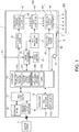
- Fig. 1 is a block diagram showing an overall configuration of a projector 1 according to the embodiment.
- the projector 1 is an apparatus that is connected to an external image supply apparatus (not shown), such as a personal computer and a variety of video image players, and projects input image data S1 inputted from the image supply apparatus onto a projection surface, such as a screen SC.
- the image supply apparatus described above may include a video reproduction apparatus, a DVD reproduction apparatus, a television tuner, a CATV set-top box, a video game console and other video image output apparatus, and a personal computer.
- the present embodiment will be described with reference to a case where the image supply apparatus inputs digital image data formed of motion images as the input image data S1 to an image processor 15.
- the digital image data contains not only image data itself but also information on the format of the digital image data (including format of stereoscopic video images, frame rate, and other factors).
- the projector 1 can display both still images and motion images (video images).
- motion images video images
- the following description will be made with reference to a case where motion images inputted from the image supply apparatus are outputted and displayed, and the process of displaying the input image data S1 in the following description is directly applicable to a case where still images are displayed.
- the projector 1 is broadly formed of a projection unit 40 (projection section), which forms an image to be projected on a projection object, and an image processing system that electrically processes the image displayed by the projection unit 40.
- the projection unit 40 is formed of a light source portion 41, a light modulator 42 (modulation section), and a projection system 43.
- the light source portion 41 includes a discharge tube 45, such as a xenon lamp or an ultrahigh-pressure mercury lamp, as a light source.
- the light source portion 41 may further include a reflector and an auxiliary reflector that guide light emitted from the discharge tube 45 to the light modulator 42.
- the light source portion 41 may still further include a group of lenses (not shown) for improving optical characteristics of projected light, a polarizer, and a light attenuator that is located in a position on a path to the light modulator 42 and reduces the amount of light emitted from the light source.
- the light modulator 42 corresponds to a modulation section that modulates light outputted from the light source portion 41 based on image data.
- the light modulator 42 is configured based, for example, on a method using three transmissive or reflective liquid crystal light valves or three digital mirror devices corresponding to RGB colors.
- the light modulator 42 may alternatively employ a DMD method using a combination of a color wheel that transmits RGB light fluxes among light fluxes contained in white light emitted from the light source and a single digital mirror device (DMD).
- DMD digital mirror device
- the light modulator 42 has a configuration based on liquid crystal light valves.
- the light modulator 42 includes transmissive liquid crystal panels each of which has a plurality of pixels arranged in a matrix, and the plurality of pixels form an image, which modulates the light emitted from the discharge tube 45.
- the light modulator 42 is driven by a light modulator driver 17, which will be described later, and forms an image by changing light transmittance of each of the pixels arranged in a matrix.
- the projection system 43 includes a group of lenses that enlarge and reduce an image to be projected and adjust focusing, a zoom adjustment motor for zoom factor adjustment, a focus adjustment motor for focus adjustment, and a lens shift motor for lens shifting.
- the projection system 43 projects the light modulated by the light modulator 42 (image light) toward the screen SC, and the group of lenses form an image on the screen SC.
- a lens exposed through a main body of the projector 1 is called a projection lens 46.
- the following drivers are connected to the projection unit 40: a projection system driver 18, which drives the motors provided in the projection system 43 under the control of a controller 10; and a light source driver 19 (discharge tube drive section), which drives the light source provided in the light source portion 41 under the control of the controller 10.
- a projection system driver 18 which drives the motors provided in the projection system 43 under the control of a controller 10
- a light source driver 19 discharge tube drive section
- the zoom adjustment motor is unnecessary. Further, when the focusing is manually adjusted instead of using the motorized focus adjustment mechanism, the focus adjustment motor is unnecessary. When the lens shifting is performed manually, the lens shift motor is unnecessary. In these cases, the projection system driver 18 is also unnecessary.
- an automatic or manual trapezoidal distortion correction mechanism may be provided.
- a lens cover 30 is disposed in a position in front of the projection lens 46, that is, outside the projection lens 46.
- the lens cover 30 functions as a shutter that blocks projected light from the projection unit 40.
- the lens cover 30 is movable with the aid of a manual slide mechanism (not shown) between a closed position C (closed) indicated by the broken line in Fig. 1 and an open position O (open) indicated by the solid line in Fig. 1 .
- the lens cover 30 may alternatively be movable with the aid of a motorized mechanism.
- the lens cover 30, when located in the closed position C, covers the front side of the projection lens 46 to block light having exited out of the projection lens 46.
- the projector 1 includes a cover detector 31.
- the cover detector 31 is, for example, a switch-based or optical sensor and outputs a detection value representing whether or not the lens cover 30 is located in the open position O to the controller 10.
- the controller 10 can determine whether the lens cover 30 is located in the open position O or the closed position C based on the detection value from the cover detector 31.
- the controller 10 acquires the detection value from the cover detector 31 and determines whether or not the lens cover 30 is located in the open position O to identify whether the position of the lens cover 30 is the open position O or the closed position C. In this case, the controller 10 determines that the lens cover 30 is closed when the lens cover 30 is located in a position other than the open position O.
- the cover detector 31 may alternatively be so configured that it can output a detection value representing whether or not the lens cover 30 is located in the closed position C.
- the controller 10 acquires the detection value from the cover detector 31 and determines whether or not the lens cover 30 is located in the closed position C to identify the position of the lens cover 30. That is, the controller 10 determines that the lens cover 30 is closed when the lens cover 30 is located in the closed position C, and determines that the lens cover 30 is located in the open position O when the lens cover 30 is not located in the closed position C (when the lens cover 30 is located in a position other than the closed position C).
- the cover detector 31 may output a detection value representing whether the lens cover 30 is located in the open position O or the closed position C.
- the controller 10 determines whether the lens cover 30 is located in the open position O or the closed position C based on the detection value from the cover detector 31.
- the image processing system is configured based on the controller 10, which works as a key component and oversees and controls the entire projector 1.
- the image processing system includes a storage unit 11, an input processor 13, an image processor 15, and a light modulator driver 17.
- the storage unit 11 stores data processed by the controller 10, a program executed by the controller 10, and other information.
- the input processor 13 detects operation performed via an operation panel 51 and a remote control light receptor 52 and outputs an operation signal corresponding to the detected operation to the controller 10.
- the image processor 15 processes the input image data S1 under the control of the controller 10.
- the image processor 15 draws an image in a frame memory 16 on a frame basis based on the input image data S1, produces an image signal based on which the drawn image is displayed, and outputs the image signal to the light modulator driver 17.
- the light modulator driver 17 drives the light modulator 42 to draw the image based on the image signal outputted from the image processor 15.
- the controller 10 reads and executes a control program stored in the storage unit 11 to control the components of the projector 1.
- the controller 10 detects details of operation performed by a user based on the operation signal inputted from the input processor 13.
- the controller 10 controls the image processor 15, the light modulator driver 17, the projection system driver 18, and the light source driver 19 in correspondence with the detected operation to project video images on the screen SC.
- the operation panel 51 which includes a variety of switches operated by the user and a variety of indicators, is disposed on the main body of the projector 1.
- the operation panel 51 is connected to the input processor 13.
- an operation signal corresponding to the operated switch is outputted from the input processor 13 to the controller 10.
- the input processor 13 causes an indicator on the operation panel 51 to light up or blink as appropriate in accordance with the action or setting state of the projector 1 under the control of the controller 10.
- the projector 1 is provided with a remote control 5 operated by the user.
- the remote control 5 has a variety of buttons and outputs an infrared signal in correspondence with operation of any of the buttons.
- the remote control light receptor 52 which receives the infrared signal outputted from the remote control 5, is disposed on the main body of the projector 1.
- the remote control light receptor 52 decodes the infrared signal received from the remote control 5, produces an operation signal representing details of the operation performed via the remote control 5, and outputs the operation signal to the controller 10.
- the storage unit 11 formed, for example, of a flash memory, stores the control program and data described above and OSD image data 11A.
- the OSD image data 11A is another type of image data different from the input image data S1 and superimposed on an image based on the input image data S1, and the combined image is displayed on the screen SC.
- the OSD image data 11A is, for example, an image of a menu screen displayed when the user makes the setting of a function of the projector 1.
- image data on a setting screen 60 ( Fig. 3 ), which will be described later, is stored as the OSD image data 11A.
- the storage unit 11 can store a plurality of types of OSD image data 11A.
- the controller 10 reads OSD image data 11A stored in the storage portion 11 and corresponding to the details of a process to be carried out.
- the controller 10 instructs the image processor 15 to carry out a process of superimposing the read OSD image data 11A on the input image data S1 and display the combined data.
- the image processor 15 draws a combined image produced by superimposing the OSD image data 11A on image data in each frame of the input image data S1 by using the frame memory 16.
- the image processor 15 outputs a display signal carrying the combined image drawn in the frame memory 16 to the light modulator driver 17.
- the light modulator driver 17 draws the combined image on the liquid crystal panel of the light modulator 42.
- the combined image is thus projected on the screen SC.
- the controller 10 can alternatively display only the OSD image data 11A on the screen SC without displaying the input image data S1. In this case, the background of the OSD image data 11A has a preset background color.
- the storage unit 11 further stores setting data 11B.
- the setting data 11B are data set by the user who operates the operation panel 51 or the remote control 5. For example, the user sets details of a setting item in the setting screen displayed by the controller 10 based on the OSD image data 11A, and the thus set details are stored as the setting data 11B.
- the controller 10 refers to the setting data 11B when controlling the components of the projector 1 and operates in accordance with the details set in the setting data 11B.
- the controller 10 which executes the program stored in the storage unit 11, functions as a projection control portion 101, an electric power control portion 102 (electric power control section), a setting processing portion 103 (setting section), and a timer 104.
- the projection control portion 101 controls the image processor 15, the light modulator driver 17, the projection system driver 18, and the light source driver 19 to project an image based on the input image data S1 on the screen SC.
- a normal projection state refers to a state in which the discharge tube 45 emits light, the light modulator 42 forms an image, and projected light reaches the screen SC.
- the light source driver 19 may supply the discharge tube 45 with rated electric power of the discharge tube 45.
- the projection control portion 101 In a period during which no input image data S1 is inputted and no detection signal is inputted from the input processor 13, the projection control portion 101 counts the duration of the state in which no detection signal is inputted (hereinafter referred to as non-operation period). The projection control portion 101 uses the timer 104 to count the non-operation period. When the non-operation period becomes equal to a preset sleep set period, the projection control portion 101 causes the projector to enter a sleep mode. The action in the sleep mode corresponds to a sleep action. The projection control portion 101 controls the image processor 15 and the light modulator driver 17 to cause the light modulator 42 to draw a plain black image (projected image).
- the projection control portion 101 may switch the electric power supplied from the light source driver 19 to the discharge tube 45 to electric power in a power saving mode, as will be described later. Moreover, after an OFF set period (second predetermined period) elapses, the electric power supplied to the discharge tub 45 is reduced to zero.
- the projection control portion 101 may disable the functions of the controller 10 except a function of detecting an operation signal from the input processor 13 and may further disable the functions of the image processor 15, the light modulator driver 17, the projection system driver 18, and the light source driver 19. In this case, the electric power consumed in a period during which the operation panel 51 or the remote control 5 is not operated can be reduced.
- the projected image in the sleep mode is not necessarily a plain black image but may be a plain blue image or a logo image.
- the projection control portion 101 When the user operates the operation panel 51 or the remote control 5 to issue an instruction of performing a mute action, the projection control portion 101 starts the mute action. In the mute action, projection of input image data S1 on the screen SC is temporarily terminated. During the mute action, the controller 10 controls the image processor 15 and the light modulator driver 17 to cause the light modulator 42 to draw a plain black or blue image or a logo image. The mute action can be performed even when input image data S1 is being inputted. After a mute timer (third predetermined period) elapses, the projection control portion 101 may switch the electric power supplied from the light source driver 19 to the discharge tube 45 to the electric power in the power saving mode, as will be described later.
- the projection control portion 101 may disable the functions of the controller 10 except the function of detecting an operation signal from the input processor 13. Further, the functions of the image processor 15, the light modulator driver 17, the projection system driver 18, and the light source driver 19 may also be disabled. In this case, the electric power consumed in a period during which the operation panel 51 or the remote control 5 is not operated can be reduced.
- the projection control portion 101 When the user operates the remote control 5 or the operation panel 51 during the mute action to instruct termination of the mute action, the projection control portion 101 returns to the normal mode.
- the projection control portion 101 determines the position of the lens cover 30 based on the detection value from the cover detector 31. Having determined that the lens cover 30 is located in the closed position C, the projection control portion 101 performs a cover close mode action to stop projecting image light on the screen SC.
- the projection control portion 101 controls the image processor 15 and the light modulator driver 17 to cause the light modulator 42 to draw a plain black image.
- the cover close mode action can be performed even when input image data S1 is being inputted.
- the projection control portion 101 may switch the electric power supplied from the light source driver 19 to the discharge tube 45 to electric power one step lower than that in the normal projection state, as will be described later. Further, after an OFF set period (fifth predetermined period) elapses, the electric power supplied to the discharge tube 45 is reduced to zero.
- the projection control portion 101 Having determined that the lens cover 30 is located in the open position O during the cover close mode, the projection control portion 101 returns to the normal mode.
- the projection control portion 101 continues performing the cover close action until determining that the lens cover 30 is located in the open position O even when input image data S1 is inputted or the remote control 5 or the operation panel 51 is operated. Having determined that the lens cover 30 is located in the open position O based on the detection value from the cover detector 31, the projection control portion 101 returns to the normal projection state.
- the projection control portion 101 may therefore disable the functions of the controller 10 during the cover close action except the function of acquiring a detection value from the cover detector 31 to determine the position of the lens cover 30. Further, the functions of the image processor 15, the light modulator driver 17, the projection system driver 18, and the light source driver 19 may be disabled. In this case, the electric power consumed in a period during which the lens cover 30 is closed can be reduced.
- a feature of the invention resides in the transition to the power saving mode in the sleep mode, the mute action, the cover close action performed by the projection control portion 101 and the return from the power saving mode.
- the same transition and return actions may be performed when a no signal input state continues and when an input signal detection state continues.
- the electric power control portion 102 controls the light source driver 19 to change the electric power supplied to the discharge tube 45.
- the light source driver 19 not only outputs rated electric power to the discharge tube 45 but also changes the supplied electric power within a range including the rated electric power and electric power lower than the rated electric power.
- the value of the electric power supplied from the light source driver 19 to the discharge tube 45 is referred to as an electric power level or simply a level.
- the light source driver 19 may change the level of a voltage outputted therefrom stepwise. In this case, the number of levels to which the output voltage is changed is not limited to a specific value.
- the discharge tube 45 to which electric power of the rated level is supplied emits light of luminance that satisfies the specifications of the discharge tube 45, whereas the discharge tube 45 to which electric power slightly lower than the rated level is supplied can emit light of luminance lower than that specified in the specifications. Further, the discharge tube 45 to which electric power greatly lower than the rated level is supplied can emit light of luminance further lower than that specified in the specifications.
- the present inventors have paid attention to the fact that when the electric power supplied to the discharge tube 45 is greatly lower than the rated level but the duration of the low electric power state is within a predetermined period, the problems will not occur.
- the present inventors have further paid attention to a fact that when the supplied electric power level is raised to the rated level, appropriately adjusting the speed at which the electric power is changed prevents the problems from occurring.
- the electric power control portion 102 controls the light source driver 19 to perform the following three action modes: the normal mode; a low luminance mode; and the power saving mode.
- the normal mode is an action mode in which the electric power supplied to the discharge tube 45 is set to the rated level (280 W, for example, or 100%).
- the low luminance mode is an action mode in which the electric power supplied to the discharge tube 45 is set to a level slightly lower than the rated level (200 W, for example, or about 70%).
- the power saving mode is an action mode in which the electric power supplied to the discharge tube 45 is set to a level greatly lower than the rated level (50% or lower, for example, or preferably about 20% to 30%) but a small degree of light emission of the discharge tube 45 can be maintained.
- the electric power control portion 102 has a function of limiting the duration of the power saving mode and a function of limiting the speed at which the supplied power level is raised from the level in the power saving mode. That is, the electric power control portion 102 monitors the period from the time when the power saving mode starts and powers off the projector 1 when a preset OFF period elapses so that the power saving mode does not continue for a period equal to or longer than the preset period.
- the electric power control portion 102 restricts the speed at which the level of the electric power supplied to the discharge tube 45 is changed.
- the level changing speed is set to a speed lower than the speed at which the level of the electric power supplied to the discharge tube 45 is raised from that in the low luminance mode to that in the normal mode.
- the electric power control portion 102 When the supplied electric power level is changed from that in the normal mode to that in the low luminance mode and from that in the low luminance mode to that in the normal mode, the electric power control portion 102 does not restrict the speed at which the supplied electric power level is changed. In this case, the electric power supplied from the light source driver 19 to the discharge tube 45 is changed at a speed achievable by a circuit in the light source driver 19. The speed is called a speed at which the supplied electric power level is normally changed (normal speed). On the other hand, when the supplied electric power level is lowered to that in the power saving mode and raised from that in the power saving mode, the electric power control portion 102 sets the speed at which the light source driver 19 changes the supplied electric power level at a speed slower than the normal speed.
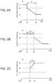
- Figs. 2A to 2C are graphs showing the change in the electric power supplied to the discharge tube 45.
- Fig. 2A shows an example in which the action mode is changed from the normal mode to the power saving mode when the mute action or the cover close action is performed.
- Fig. 2B is an example in which the supplied electric power is changed from that in the normal mode to that in the power saving mode when the sleep mode is performed.
- Fig. 2C shows an example in which the action mode is changed from the power saving mode to the normal mode.
- the vertical axis represents the electric power (W) supplied to the discharge tube 45
- the horizontal axis represents time.
- the supplied electric power levels described above are indicated along the vertical axis as follows: N is the rated level (rated electric power level); N' is the level in the low luminance mode; and L is the level in the power saving mode (power saving level).
- the electric power control portion 102 controls the light source driver 19 to change the level of the electric power supplied to the discharge tube 45 from the level N to the level N' (time t1), as shown in Fig. 2A .
- the level N is changed to the level N' at the normal speed, and the supplied electric power is therefore quickly changed as shown in Fig. 2A .
- the electric power control portion 102 subsequently changes the level of the electric power supplied to the discharge tube 45 from the level N' to the level L in a period T1 from the time t1 to t2.
- the speed at which the supplied electric power level is changed in the period T1 is a preset speed slower than the normal speed (about 10 W/sec, for example).
- the control shown in Fig. 2A is performed by the electric power control portion 102, for example, when the projection control portion 101 performs the mute action or the cover close action.
- the action mode is changed to the power saving mode, for example, 20 seconds (t2) after any of the actions described above (t1). In other words, it takes for example 20 seconds to change the power from N' to L.
- the electric power control portion 102 When the projector enters the sleep mode, the electric power control portion 102 performs control that changes the electric power supplied to the discharge tube 45 to that in the power saving mode. In this case, the electric power control portion 102, for example, maintains the level of the electric power supplied to the discharge tube 45 for a predetermined period T2, as shown in Fig. 2B .
- the action mode returns from the power saving mode to the normal action mode, it takes a certain period to raise the supplied electric power level as described above. Therefore, when the projector enters the sleep mode, changing the action mode to the power saving mode undesirably causes the user to wait when the projector returns from the sleep mode.
- the electric power control portion 102 waits for a period (period T2; from t3 to t4; five minutes, for example) after the projection control portion 101 causes the projector to enter the sleep mode.
- the electric power control portion 102 causes the projector to enter the power saving mode.
- the level of the electric power supplied to the discharge tube 45 is lowered when the period T2 elapses (time t4) in Fig. 2B .
- the speed at which the supplied electric power level is lowered from the level N to the level N' at the time t4 is the normal speed described above, and the level is therefore quickly lowered in Fig. 2B .
- the electric power control portion 102 After the time t4 in Fig. 2B , that is, in a process of lowering the supplied electric power from the level N' to the level L, the electric power control portion 102 performs control that restricts the speed at which the supplied electric power level is changed, as in the period T1 shown in Fig. 2A .
- the electric power control portion 102 raises the supplied electric power level as shown, for example, in Fig. 2C .
- the electric power control portion 102 raises the supplied electric power level from the electric power level L in the power saving mode to an intermediate level M (time t5).
- the intermediate level M is a predetermined electric power level between the level L and the rated level N. It has been experimentally shown that even when the electric power supplied to the discharge tube 45 is sharply changed between the level L and the level M, no damage is made to the discharge tube 45.
- the electric power control portion 102 sharply changes the supplied electric power level to the level M in order to shorten the period required to return the normal mode.
- the speed at which the supplied electric power level is changed from the level L to the level M is the normal speed described above.
- a specific value of the level M is determined based, for example, on the specifications of the discharge tube 45 and is, for example, 60% of the rated value.
- the level M may be a limit determined based, for example, on the specifications of the discharge tube 45 or may be the limit from which a predetermined safety margin is subtracted.
- the electric power control portion 102 then raises the supplied electric power level from the level M to the level N while restricting the speed at which the level of the electric power supplied to the discharge tube 45 to a fixed value or lower in a period T3 in Fig. 2C .
- the level changing speed in the period T3 is a preset speed or slower that causes the user to wait until time t6.
- the speed at which the supplied electric power level is changed in the period T3 may be equal to the speed in the period T1 shown in Fig. 2A or may be a speed different therefrom.
- 2C is performed by the electric power control portion 102 after the sleep mode, the mute action, the cover close action, the no signal input state, the input signal detection state, or any other action or state which causes the action mode to be changed to the power saving mode and when the action mode returns to the normal mode.
- the mute action is terminated and the action mode returns to the normal mode (level N) after about 10 to 15 seconds or to the low luminance mode (Level N') in some cases (in a case where the action mode is the low luminance mode and then changed to the power saving mode) (t6).
- the electric power control portion 102 controls the electric power supplied to the discharge tube 45 to cause the projector 1 to enter the power saving mode for power saving in the projector 1.
- the lengths of T1, T2 (sleep set period), and T3, the length of each of the OFF set periods, and the speed at which the supplied electric power levels change in each of the periods T1 and T3 are set in advance and stored as the setting data 11B.
- the electric power control portion 102 performs the control described above in accordance with the details set in the setting data 11B.
- the electric power control portion 102 may always perform the control shown in Figs. 2A to 2C . In the present embodiment, however, the user can choose whether or not the action mode is changed to the power saving mode when the non-projection control is performed.
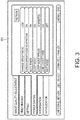
- Fig. 3 shows an example of the setting screen 60, which allows the user to choose whether or not the action mode is changed to the power saving mode.
- the setting screen 60 shown in Fig. 3 is displayed on the screen SC based on the function of the projection control portion 101 that controls the image processor 15 based on the OSD image data 11A.
- the projection control portion 101 reads the OSD image data 11A and causes the projection unit 40 to display the setting screen 60. After the setting screen 60 is displayed, the user can operate the remote control 5 or the operation panel 51 to select each setting item in the setting screen 60 and determine details of the setting item.
- the setting processing portion 103 acquires the details determined by the setting operation and stores the details as the setting data 11B on a setting item basis. When details having been already set are changed, the setting processing portion 103 updates the setting data 11B in accordance with the changed details of the setting item.
- the following items are arranged: "mute timer;” “sleep mode;” “sleep mode period;” and “lens cover timer.”
- the user operates the remote control 5 or the operation panel 51 to select any of the setting items and chooses whether or not the power saving mode is performed.
- the name of the setting item "mute timer” in the setting screen 60 means that it allows the user to activate a function of performing the mute action in such a way that the mute action continues for a predetermined period and then the projector 1 is powered off.
- "Mute timer” has two setting values, “timer on” and “timer off.”
- the setting value is "timer on”
- the electric power control portion 102 causes the projector 1 to enter the power saving mode when the mute action is performed, and the timer powers off the projector 1 after the mute action continues for the predetermined period.
- the setting value is "timer off”
- the projector 1 is not powered off even when the mute action continues for a period longer than the predetermined period.
- the electric power control portion 102 does not cause the projector to enter the power saving mode.
- the predetermined period associated with "mute timer” is so set that the problems with the discharge tube 45 will not occur even when the level of the electric power supplied to the discharge tube 45 is changed to the power saving level and is, for example, 30 minutes.
- the power saving mode is performed during the mute action, the projector 1 needs to be powered off after the mute action continues for 30 minutes in order to prevent the problems with the discharge tube 45 from occurring. Only when the user chooses the action on the projector 1 described above, that is, the action of powering off the projector 1 after 30 minutes elapses, the electric power control portion 102 can perform the power saving mode.
- the names of the setting items "sleep mode” and “sleep mode period” in the setting screen 60 mean that it allows the user to activate a function of powering off the projector 1 after the sleep mode continues for a predetermined period.
- "Sleep mode” has two setting values, “timer on” and “timer off.” When the setting value is "timer on,” the projection control portion 101 can perform the sleep mode, and the electric power control portion 102 causes the projector to enter the power saving mode in the sleep mode.
- the “sleep mode period” can be set only when the setting value of the "sleep mode” is “timer on.”
- “Sleep mode period” has three setting values, "10 minutes,” “20 minutes,” and “30 minutes” or has specifications that do not allow the user to set “sleep mode period” in such a way that the sleep mode continues for a period longer than 30 minutes.
- the specifications limit the period during which the electric power control portion 102 performs the power saving mode to 30 minutes at longest.
- the electric power control portion 102 can perform the power saving mode only when the sleep mode period is so set that the sleep mode continues for a period shorter than or equal to 30 minutes and then the projector 1 is powered off.
- the name of the setting item "lens cover timer” in the setting screen 60 means that it allows the user to activate a function of powering off the projector 1 when it is determined that the lens cover 30 is located in the closed position C and after the cover close action continues for a predetermined period.
- the “lens cover timer” has two setting values, “timer on” and “timer off.”
- the setting value is "timer on”
- the electric power control portion 102 causes the projector 1 to enter the power saving mode when the cover close action is performed, and the timer powers off the projector 1 after the cover close action continues for the predetermined period.
- the setting value is "timer off”
- the projector 1 is not powered off even when the cover close action continues for a period longer than the predetermined period.
- the electric power control portion 102 does not cause the projector to enter the power saving mode.
- the predetermined period associated with the "lens cover timer” is so set that the problems with the discharge tube 45 will not occur even when the level of the electric power supplied to the discharge tube 45 is changed to the power saving level, and is specifically 30 minutes described above.
- the power saving mode is performed during the cover close action, the projector 1 needs to be powered off after the cover close action continues for 30 minutes in order to prevent the problems with the discharge tube 45 from occurring.
- the setting items in the setting screen 60 that are associated with the non-projection action of the projection control portion 101 are configured to allow the user to choose whether or not to perform the action of the projector 1 required to prevent the problems with the discharge tube 45 from occurring when the power saving mode is performed.
- the electric power control portion 102 can perform the power saving mode only when the user chooses to allow the projector 1 to perform the action required to prevent the problems with the discharge tube 45 resulting from the power saving mode from occurring and sets the projector 1 to perform the action.
- the power saving mode can be performed only when the user allows the projector 1 to perform the action required in association with performing the power saving mode.
- the problems with the discharge tube 45 resulting from long duration of the power saving mode will not occur.
- the action of the projector 1 required when the power saving mode is chosen is not performed unless the user intentionally sets the projector 1 to perform the action, and power saving can be effectively achieved without compromising the convenience of the user.
- Fig. 4 is a flowchart showing the action of the projector 1.
- Fig. 4 shows action involved in the sleep mode and a series of action involved in the mute action of the projector 1.
- the projector 1 enters the sleep mode when a state in which the operation panel 51 or the remote control 5 is not operated or a state in which no input image data S1 is inputted continues in the normal action state. Further, when the user issues an instruction of performing the mute action during the normal action state or during the sleep mode, the projector 1 starts the mute action in response to the instruction.
- step S11 the controller 10 performs the normal action and waits for operation of the operation panel 51 or the remote control 5, an input of input image data S1, or any other input (step S11).
- the function of the timer 104 is used to start counting the wait period. The count action then continues as long as no input is received.
- the projection control portion 101 determines whether or not an input has been received whenever a predetermined period elapses (step S12). When no input has been received (step S12; No), the projection control portion 101 refers to the setting data 11B and determines whether or not the sleep mode has been activated (step S13). When the sleep mode can be activated, the sleep action described above is performed, whereas when the sleep mode is deactivated, the sleep action described above cannot be performed. When the sleep mode is deactivated (step S13; No), the projector does not enter the sleep mode (returns to step S12).
- the projection control portion 101 When the sleep mode is activated (step S13; Yes), the projection control portion 101 refers to the count of the wait period, the counting of which has started in step S11. The projection control portion 101 then determines whether or not the wait period has become equal to a set period based on which the sleep action starts (step S14).
- the set period is a latency after which the sleep action starts in a no input state and is, for example, 20 seconds and stored as the setting data 11B.
- the projection control portion 101 returns to step S12 and keeps waiting.
- the projection control portion 101 causes the projector to enter the sleep mode (step S15).
- step S15 where the projection control portion 101 causes the projector to enter the sleep mode, the projection control portion 101 controls the light modulator 42, for example, to display a plain black image. Further, in step S15, the projection control portion 101 resets the count of the wait period having been counted by the timer 104 and starts counting the sleep period.
- the projection control portion 101 waits for an input (such as pressing operation performed on remote control, pressing operation performed on operation panel, and incoming input signal) (step S16).
- the projection control portion 101 determines in step S16 whether or not an input has been received whenever a predetermined period elapses.
- the projection control portion 101 returns to the normal projection state (step S17).
- the projection control portion 101 proceeds to step S24, which will be described later, to perform an action corresponding to the input.
- step S16 When no input has been received (step S16; No), the projection control portion 101 refers to the count of the sleep period, the counting of which has started in step S15. The projection control portion 101 then determines whether or not the sleep period has become equal to a preset period (first predetermined period) (step S18).
- the "first predetermined period" in the determination process in step S18 corresponds to the wait period T2 shown in Fig. 2B .
- step S18 When the sleep period has not become equal to the first predetermined period (step S18; No), the projection control portion 101 returns to step S16.
- step S18 when the sleep period has become equal to the first predetermined period (step S18; Yes), the electric power control portion 102 controls the light source driver 19 to change the electric power supplied to the discharge tube 45 from that in the normal mode to that in the power saving mode (step S19).
- step S19 the electric power control portion 102 changes the electric power supplied from the light source driver 19, as shown in Fig. 2B .
- step S19 the projection control portion 101 resets the count provided by the timer 104 and starts counting the duration of the power saving mode.
- the projection control portion 101 determines whether or not an input has been received whenever a predetermined period elapses (step S20). When an input has been received (step S20; Yes), the projection control portion 101 returns to the normal projection state (step S21). After returning to the normal projection state, the projection control portion 101 proceeds to step S24, which will be described later, to perform an action corresponding to the input.
- step S21 the electric power control portion 102 changes the electric power supplied to the discharge tube 45 from that in the power saving mode back to that in the normal mode.
- the electric power control portion 102 first raises the supplied electric power level from the supplied electric power level in the power saving mode (level L) to the intermediate level (level M), as shown in Fig. 2C .
- the electric power control portion 102 subsequently raises the supplied electric power level from the intermediate level to the rated electric power level N at a restricted speed.
- step S20 When no input has been received (step S20; No), the projection control portion 101 refers to the count of the duration of the power saving mode, the counting of which has started in step S19. The projection control portion 101 then determines whether or not the count of the duration of the power saving mode has reached a preset period (second predetermined period) (step S22).
- the "second predetermined period" in the determination process in step S22 is the setting value of "sleep mode period" set in the setting screen 60 ( Fig. 3 ).
- step S22 When the duration of the power saving mode has not become equal to the second predetermined period (step S22; No), the projection control portion 101 returns to step S20.
- step S22 When the duration of the power saving mode has become equal to the second predetermined period (step S22; Yes), the projector 1 is powered off (step S23) and the action thereof is terminated.
- step S12 when an input has been received (step S12; Yes, step S16; Yes + step S17, step 20; Yes + step S21), the projection control portion 101 proceeds to step S24.
- step S24 the projection control portion 101 resets the count provided by the timer 104 that is performing counting.
- the projection control portion 101 subsequently determines whether or not the input corresponds to a mute action performing instruction issued by the user who operates the operation panel 51 or the remote control 5 (step S25).
- step S25 When the input does not correspond to the mute action performing instruction (step S25; No), the projection control portion 101 performs an action corresponding to the input (step S26) and returns to step S11.
- the projection control portion 101 starts the mute action and, for example, controls the light modulator 42 to display a plain black or blue image or a logo image (step S27).
- the projection control portion 101 then refers to the setting data 11B and determines whether the setting value in the mute timer setting is "timer on” or “timer off” (step S28).
- the setting value in the mute timer setting is the third predetermined period set based on the "mute timer" item in the setting screen 60 ( Fig. 3 ).
- step S28 When the setting value of the mute timer is "timer off" (step S28; No), which means that the mute timer has not been set, the projection control portion 101 does not change the electric power supplied to the discharge tube 45 but waits for operation of instructing return from the mute action (step S29).
- step S29 When the instruction of return from the mute action has been received (step S29; Yes), the projection control portion 101 terminates the mute action and instructs the light modulator 42 to stop displaying the plain black image or any other image, changes the projection state back to the normal projection state (step S30), and returns to step S11.
- step S28 When the setting value of the mute timer is "timer on” (step S28; Yes), the projection control portion 101 starts counting the duration of the mute action by using the timer 104, and the electric power control portion 102 causes the projector to enter the power saving mode (step S31).
- step S31 the electric power control portion 102 changes the electric power supplied from the light source driver 19 as shown in Fig. 2A .
- the projection control portion 101 determines whenever a predetermined period elapses whether or not operation of instructing return from the mute action (pressing mute button on remote control or operation panel) has been performed (step S32).
- the projection control portion 101 terminates the mute action to return to the normal projection state and resets the count provided by the timer 104 (step S33).
- the electric power control portion 102 causes the projector to enter the normal mode from the power saving mode (step S34).
- the electric power control portion 102 raises the supplied electric power level from that in the power saving mode to the intermediate level M and then raises the supplied electric power level to the rated level N at a predetermined speed or slower.
- step S32 When no instruction of return from the mute action has been received (step S32; No), the projection control portion 101 refers to the count of the duration of the mute action, the counting of which has started in step S31. The projection control portion 101 then determines whether or not the count of the duration of the power saving mode has reached a preset period (fourth predetermined period) (step S35).
- the "fourth predetermined period" in the determination process in step S35 is the predetermined period associated with "mute timer" preset as described above.
- step S35 When the duration of the power saving mode has not become equal to the fourth predetermined period (step S35; No), the projection control portion 101 returns to step S32.
- step S35 When the duration of the power saving mode has become equal to the fourth predetermined period (step S35; Yes), the projector 1 is powered off (step S36), and the action thereof is terminated.
- Fig. 5 is another flowchart showing the action of the projector 1.
- Fig. 5 shows a series of action involved in the cover close action of the projector 1.
- the actions in Fig. 5 start when the projector 1 operates in the normal action state and the projection control portion 101 detects that the lens cover 30 is not located in the open position O based on the detection value from the cover detector 31 (step S41).
- the normal operation state includes a state in which the projection control portion 101 waits for an input after the projector 1 is powered on and a state in which the projection control portion 101 displays an image on the screen SC based on input image data S1.
- the projection control portion 101 determines whether the setting value of the lens cover timer is "timer on” or “timer off” (step S42).
- the setting value of the lens cover timer is set based on the setting screen 60 ( Fig. 3 ) and stored as the setting data 11B.
- the projection control portion 101 When the setting value of the lens cover timer is "timer off," which means that the lens timer is not working, the projection control portion 101 performs, for example, an action of instructing the light modulator 42 to display a plain black image (cover close action) (step S43) and then waits without changing the electric power supplied to the discharge tube 45 until the lens cover 30 is located in the open position O (step S44).
- cover close action an action of instructing the light modulator 42 to display a plain black image
- step S44 waits without changing the electric power supplied to the discharge tube 45 until the lens cover 30 is located in the open position O
- the projection control portion 101 detects that the lens cover 30 is open based on the detection value from the cover detector 31 (step S44; Yes)
- the projection control portion 101 changes the display state back to the normal projection state in which input image data are displayed (step S45) and returns to step S41.
- step S42 when the setting value of the lens cover timer is "timer on" (step S42; Yes), the projection control portion 101 performs the cover close action (step S46) and causes the projector to enter the power saving mode to lower the electric power supplied to the discharge tube 45 to the power saving level (step S47).
- step S47 the projection control portion 101 resets the count provided by the timer 104 and starts counting the duration of the power saving mode.
- the projection control portion 101 determines whether or not the lens cover 30 is located in the open position O (step S48). Having detected that the lens cover 30 is located in the open position O (step S48; Yes), the projection control portion 101 changes the projection state back to the normal projection state (step S49) and returns to step S41.
- the electric power control portion 102 causes the projector to enter the normal mode from the power saving mode.
- the electric power control portion 102 raises the supplied electric power level from the supplied electric power level in the power saving mode to the intermediate level M and then raises the supplied electric power level to the rated level at a predetermined speed or slower, as shown in Fig. 2C .
- the projection control portion 101 refers to the count of the duration of the power saving mode, the counting of which has started in step S47. The projection control portion 101 then determines whether or not the count of the duration of the power saving mode has reached a preset period (fifth predetermined period) (step S50).
- the "fifth predetermined period" in the determination process in step S49 is the predetermined period associated with the "lens cover timer" preset as described above.
- step S50 When the duration of the power saving mode has not become equal to the fifth predetermined period (step S50; No), the projection control portion 101 returns to step S48.
- step S50 When the duration of the power saving mode has become equal to the fifth predetermined period (step S50; Yes), the projector 1 is powered off (step S51) and the action thereof is terminated.
- the projector 1 is the projector 1 including the discharge tube 45 as the light source and further including the light source driver 19 and the electric power control portion 102.
- the projector 1 uses the light source driver 19 to supply the discharge tube 45 with electric power.
- the projector 1 uses the electric power control portion 102 to control the level of the electric power supplied from the light source driver 19 to the discharge tube 45 to perform the normal mode, in which the light source driver 19 supplies electric power of the rated electric power level, and the power saving mode, in which the light source driver 19 supplies electric power of the power saving level lower than the rated electric power level.
- the electric power control portion 102 changes the level of the electric power supplied from the light source driver 19 to the discharge tube 45 in a restricted manner.
- the configuration described above which changes the electric power supplied to the discharge tube 45 to the power saving level, allows power saving. Further, when the electric power supplied to the discharge tube 45 is changed from the power saving level to the rated electric power level in the normal state, the electric power level is changed in a restricted manner to prevent a sharp change in the electric power level. As a result, even when the supplied electric power is reduced to an electric power level where it is feared that the life of the discharge tube 45 is undesirably affected, no damage is made to the discharge tube 45 when the electric power level is changed back to that in the normal state. The electric power supplied to the discharge tube 45 can thus be greatly reduced as compared with a case in related art, and power saving in the projector 1 can be effectively achieved.
- the electric power control portion 102 changes the electric power level in a restricted manner at least from the intermediate level (level M), which is higher than the power saving level (level L), to the rated electric power level (level N).
- the electric power level can be changed between the levels L and M in a non-restricted manner.
- the electric power level can therefore be controlled in the following two ways: The electric power level is so changed in a restricted manner that the life of the discharge tube 45 is not affected; and the electric power level is quickly changed to the extent that the life of the discharge tube 45 is not affected.
- the electric power control portion 102 raises the electric power level from the level M to the level N at a slower speed than the speed in the process of changing the electric power level from the level L to the level M.
- the electric power control portion 102 raises the electric power level from the level M to the level N at a slower speed than the speed in the process of changing the electric power level from the level L to the level M.
- the projector 1 further includes the projection unit 40 including the discharge tube 45, the light modulator 42, and the projection system 43. Further, the projection control portion 101 controls the projection unit 40 to perform the projection control, in which light is projected, and the non-projection control, in which the projection section performs no projection.
- the electric power control portion 102 causes the projector to enter the power saving mode when the projection control portion 101 performs the non-projection control including a process of turning off the discharge tube 45.
- the non-projection control includes the sleep mode, the mute action, and the cover close action.
- the mute action, the sleep action, the cover close action, or an action including a process of turning off the discharge tube 45 is performed, the electric power supplied to the discharge tube 45 can be reduced, whereby power saving is effectively achieved.
- the mute action, the sleep action, or the cover close action is changed back to the normal action state, the electric power level is changed in a restricted manner, whereby the life of the discharge tube 45 is not affected even when the power saving level is set at a small value.
- the electric power control portion 102 does not cause the projector to enter the power saving mode until a preset period elapses after the projection control portion 101 causes the projector to enter the sleep mode.
- the operation is performed in a short period after the sleep action starts, whereby the latency required to return from the sleep action to the normal action state can be shortened.
- the electric power control portion 102 changes or lowers the level of the electric power supplied to the discharge tube 45 in a restricted manner when the action mode is changed from the normal mode to the power saving mode as shown in the period T1 in Fig. 2A and the period T2 in Fig. 2B .
- the power saving level is set at an electric power level so low that it is feared that the life of the discharge tube 45 is undesirably affected, no damage is made to the discharge tube 45 in the process of lowering the electric power level.
- the electric power control portion 102 can set the electric power supplied to the discharge tube 45 at a low luminance level (level N' shown in Fig. 2A ) lower than the rated electric power level but higher than the power saving level.
- a low luminance level level N' shown in Fig. 2A
- the electric power level is changed in a non-restricted manner until the level N' is reached, but the electric power level is changed in a restricted manner in the process of lowering the electric power level from the level N' to the level L.
- the electric power level can be controlled in the following two ways: The electric power level is quickly lowered to the extent that the life of the discharge tube 45 is not affected; and the electric power level is lowered at a speed so low that the life of the discharge tube 45 is not affected.
- the electric power control portion 102 causes the projector to enter the power saving mode based on the setting data 11B representing setting values set based on the setting screen 60.
- the user can choose whether or not the electric power supplied to the discharge tube 45 is lowered when the sleep mode, the mute action, or the cover close action is performed, whereby optimum action can be performed in consideration of the latency required when the action mode is changed from the power saving mode to the normal mode and the tendency of the user who uses the projector. Power saving in the projector 1 is therefore more effectively achieved without compromising the convenience of the user.
- the embodiment described above is only an example of a specific aspect to which the invention is applied and does not limit the scope of the invention.
- the invention is also applicable to an aspect different from the embodiment described above.
- the electric power control portion 102 in the controller 10 controls the light source driver 19 to change the electric power supplied to the discharge tube 45 by way of example.
- the invention is not necessarily configured this way.
- a section that adjusts the electric power supplied to the discharge tube 45 may be provided between the light source driver 19 and the discharge tube 45.
- the number of discharge tubes 45 provided in the projector 1 is not limited to one.
- a section that adjusts the electric power supplied to the plurality of discharge tubes 45 as a whole may be provided, or the electric power supplied to each of the discharge tubes 45 may be independently adjustable.
- the invention is not necessarily applied to the case where the electric power control portion 102 causes the projector to enter the power saving mode when the projection control portion 101 performs the sleep mode, the mute action, or the cover close action.
- the electric power control portion 102 may cause the projector to enter the power saving mode in synchronization with any other action of the projection control portion 101 or independently of the action of the projection control portion 101.
- the above embodiment has been described with reference to the case where three transmissive or reflective liquid crystal light valves corresponding to RGB colors are used as light modulators.
- the invention is not necessarily configured this way.
- a combination of a single liquid crystal light valve and a color wheel may be employed.
- a method using three digital mirror devices (DMDs) that modulate RGB color light fluxes a method using a combination of a single digital mirror device and a color wheel, or other methods may be employed.
- a member corresponding to a light combining system such as a cross dichroic prism, is not necessary.
- any configuration that can modulate light emitted from a light source can be employed with no problem instead of a liquid crystal panel or a DMD device, and other detailed configurations of the projector can be arbitrarily changed.
- the invention is applicable not only to a front projection projector that performs projection on a screen from the side where a projected image is observed but also to a rear projection projector that performs projection from the side opposite to the side where a projected image is observed.
- an apparatus to which the invention is applied is not limited to the embodiment described above, but is limited by the scope of the claims.
Description
- The present invention relates to a projector and a method for controlling the projector.
- As a light source of a projector of related art, there is a known light source using a discharge tube, such as a high-pressure mercury lamp. There is a known projector of this type in which electric power supplied to the discharge tube is reduced for power saving (see
JP-A-2012-108216 JP-A-2012-108216 - To essentially achieve power saving, electric power supply to the discharge tube only needs to be terminated (zero electric power). Once the electric power supply to the discharge tube is terminated, however, it undesirably takes a very long time to restore optical intensity of the discharge tube after the projector is restarted.
-
US 2012/206698 describes a projector, in which power is applied to a discharge tube at a given power level during a normal mode, and at a lower power level during a standby mode. During a first mode period the applied power is 100% power level equal to the rated power of the tube. In a second mode period the applied power varies cyclically between two further power levels which are, e.g., 30% and 20%, respectively, of the rated level. The lower-power mode may be entered when the user executes a mute operation. - In
JP 2000-131668 - A projector is also described in
US 2010/238418 , in which rated power is applied to a discharge lamp during a normal mode. When the user selects a low-power mode, the applied power is reduced and the duty ratio of the applied current is changed in stepwise fashion for one cycle. In a different embodiment, when the low-power mode is selected, there is a switching period during which the rated applied power is reduced in steps down to the low-power level. - In
JP H11-288790 - A projector and an image-processing system are described in
JP 2003-029341 - Another conventional projector is disclosed in
WO 2011/048928 A1 . - An advantage of some aspects of the invention is to effectively achieve power saving in a projector including a discharge tube.
- An aspect of the invention is directed to a projector as defined in
independent Claim 1, that includes a discharge tube and projects an image by using a light source including the discharge tube. The projector includes a discharge tube drive section that supplies the discharge tube with electric power and an electric power control section that controls the level of the electric power with which the discharge tube drive section supplies the discharge tube to perform a normal mode in which the discharge tube drive section supplies electric power of a rated electric power level and a power saving mode in which the discharge tube drive section supplies electric power of a power saving level lower than the rated electric power level when the image is not required to be projected, and the power saving mode is a mode in which slight light emission can be maintained. - The electric power control section may change the level of the electric power supplied to the discharge tube in a restricted manner when the power saving mode is changed back to the normal mode or when the normal mode is changed to the power saving mode.
- According to the aspect of the invention, power saving is achieved by reducing the electric power supplied to the discharge tube to the power saving level when no image is required to be projected on a screen or any other projection surface. Further, maintaining the power saving level instead of completely reducing the electric power supplied to the discharge tube to zero allows the image projection to be immediately resumed when the projection is resumed. Further, the following problems can be solved: In the power saving mode, since a pair of electrodes in the discharge tube shrink, abruptly supplying electric power of the rated level in order to restore the state in the normal mode prevents the pair of electrodes from expanding straight with respect to each other, resulting in degradation in light emission characteristics or breakage of the electrodes due to produced stress; and in the normal mode, since the pair of electrodes in the discharge tube expand, sharply reducing the supplied electric power to the level in the power saving mode prevents the pair of electrodes from shrinking straight with respect to each other, which cannot maintain light emission from the lamp.
- That is, when the electric power supplied to the discharge tube is changed from the power saving level to the rated electric power level or changed from the rated electric power level to the power saving level, changing the electric power level in a non-sharp manner allows the electrodes in the discharge tube to expand or shrink straight, preventing a damage from being made to the discharge tube.
- Further, the electric power level may be changed in a restricted manner when an intermediate electric power level higher than the power saving level is changed to the rated electric power level.
- In this case, since the electric power level is changed in a non-restricted manner when the supplied electric power level is changed from the power saving level to the intermediate electric power level, the electric power level can be controlled in the following two ways: The electric power level is so changed in a restricted manner that the life of the discharge tube is not affected; and the electric power level is quickly changed to the extent that the life of the discharge tube is not affected. As a result, not only can effective power saving be achieved but also no damage is made to the discharge tube and the period required to change the power saving mode to the normal mode can be shortened.
- Further, in the process of changing the intermediate electric power level to the rated electric power level, the level of the electric power supplied from the discharge tube drive section may be raised at a speed slower than a speed in a process of changing the power saving level to the intermediate electric power level.
- Further, a low luminance level may be set between the rated electric power level and the power saving level, and the electric power level may be changed in a restricted manner when the supplied electric power is changed from the low luminance level to the power saving level. That is, the electric power level may be changed in a non-restricted manner when the supplied electric power is changed from the rated electric power level to the low luminance level. In this case, the electric power level can be controlled in the following two ways: The electric power level is so changed in a restricted manner that the life of the discharge tube is not affected; and the electric power level is quickly changed to the extent that the life of the discharge tube is not affected. As a result, not only can effective power saving be achieved but also no damage is made to the discharge tube in the process of lowering the electric power level and the period required to change the normal mode to the power saving mode can be shortened.
- The configuration described above may further include a projection section including the discharge tube, a modulation section that modulates light emitted from the discharge tube, and a projection system that projects the light modulated by the modulation section and a projection control section that performs non-projection control in which projection performed by the projection section is terminated by carrying out a process of turning off the discharge tube and the electric power control section may cause the projector to enter the power saving mode when the projection control section performs the non-projection control.
- In this case, even when the power saving level is set at a level greatly lower than the level of the rated electric power of the discharge tube, no damage will be made to the discharge tube because the discharge tube is turned off after the power saving mode is performed, whereby more effective power saving is achieved.
- In the configuration described above, examples of the process of turning off the discharge tube may include a mute action in which the image display action is terminated, a sleep action in which the projector waits until the projector is operated, a cover close action in which a cover blocks the projection system, an elapse of a predetermined period during which no signal is inputted to the projector (not signal), and an elapse of a predetermined period during which a signal inputted to the projector is searched.
- In this case, the electric power supplied to the discharge tube can be lowered to the level in the power saving mode before the discharge tube is turned off for effective power saving.
- Further, when the power saving mode (such as mute action, sleep action, cover close action, no signal input, and input signal search) is changed back to a normal action state (normal mode), the electric power level is changed in a restricted manner.
- Further, the power saving mode may not start until a predetermined period elapses after the sleep action starts.
- In this case, even when operation of changing the power saving mode back to the normal operation state is performed after the sleep action starts but before the predetermined period elapses, the discharge tube immediately emits light because the power saving mode is not performed.
- Further, a setting section that sets whether or not the power saving mode is started may be provided, and the electric power control section may cause the projector to enter the power saving mode when the projection control section performs any of the mute action, the sleep action, the cover close action, and the other actions and the setting section sets the power saving mode to be performed in response to the action.
- In this case, optimum action can be performed in consideration of the latency required when the power saving mode is changed to the normal mode and the tendency of a user who uses the projector. Power saving in the projector is therefore more effectively achieved without compromising the convenience of the user.
- Another aspect of the invention is directed to a method for controlling a projector as defined in
independent Claim 11. - Embodiments of the invention will now be described by way of example only with reference to the accompanying drawings, wherein like numbers reference like elements.
-
Fig. 1 is a block diagram showing the configuration of a projector according to an embodiment. -
Figs. 2A to 2C are graphs showing changes in electric power supplied to a discharge tube,Fig. 2A shows an example in which a normal mode is changed to a power saving mode when a mute action or a cover close action is performed,Fig. 2B is an example in which supplied electric power is changed from that in the normal mode to that in the power saving mode when a sleep mode is performed, andFig. 2C shows an example in which the power saving mode is changed to the normal mode. -
Fig. 3 shows an example of a setting screen that allows a user to choose whether or not the power saving mode is performed. -
Fig. 4 is a flowchart showing the action of the projector. -
Fig. 5 is another flowchart showing the action of the projector. - An embodiment of the invention will be described below with reference to the drawings.
-
Fig. 1 is a block diagram showing an overall configuration of aprojector 1 according to the embodiment. Theprojector 1 is an apparatus that is connected to an external image supply apparatus (not shown), such as a personal computer and a variety of video image players, and projects input image data S1 inputted from the image supply apparatus onto a projection surface, such as a screen SC. The image supply apparatus described above may include a video reproduction apparatus, a DVD reproduction apparatus, a television tuner, a CATV set-top box, a video game console and other video image output apparatus, and a personal computer. The present embodiment will be described with reference to a case where the image supply apparatus inputs digital image data formed of motion images as the input image data S1 to animage processor 15. The digital image data contains not only image data itself but also information on the format of the digital image data (including format of stereoscopic video images, frame rate, and other factors). - The
projector 1 can display both still images and motion images (video images). The following description will be made with reference to a case where motion images inputted from the image supply apparatus are outputted and displayed, and the process of displaying the input image data S1 in the following description is directly applicable to a case where still images are displayed. - The
projector 1 is broadly formed of a projection unit 40 (projection section), which forms an image to be projected on a projection object, and an image processing system that electrically processes the image displayed by theprojection unit 40. Theprojection unit 40 is formed of alight source portion 41, a light modulator 42 (modulation section), and aprojection system 43. Thelight source portion 41 includes adischarge tube 45, such as a xenon lamp or an ultrahigh-pressure mercury lamp, as a light source. Thelight source portion 41 may further include a reflector and an auxiliary reflector that guide light emitted from thedischarge tube 45 to thelight modulator 42. Thelight source portion 41 may still further include a group of lenses (not shown) for improving optical characteristics of projected light, a polarizer, and a light attenuator that is located in a position on a path to thelight modulator 42 and reduces the amount of light emitted from the light source. - The
light modulator 42 corresponds to a modulation section that modulates light outputted from thelight source portion 41 based on image data. Thelight modulator 42 is configured based, for example, on a method using three transmissive or reflective liquid crystal light valves or three digital mirror devices corresponding to RGB colors. Thelight modulator 42 may alternatively employ a DMD method using a combination of a color wheel that transmits RGB light fluxes among light fluxes contained in white light emitted from the light source and a single digital mirror device (DMD). - In the present embodiment, the
light modulator 42 has a configuration based on liquid crystal light valves. Thelight modulator 42 includes transmissive liquid crystal panels each of which has a plurality of pixels arranged in a matrix, and the plurality of pixels form an image, which modulates the light emitted from thedischarge tube 45. Thelight modulator 42 is driven by alight modulator driver 17, which will be described later, and forms an image by changing light transmittance of each of the pixels arranged in a matrix. - The
projection system 43 includes a group of lenses that enlarge and reduce an image to be projected and adjust focusing, a zoom adjustment motor for zoom factor adjustment, a focus adjustment motor for focus adjustment, and a lens shift motor for lens shifting. Theprojection system 43 projects the light modulated by the light modulator 42 (image light) toward the screen SC, and the group of lenses form an image on the screen SC. Among the group of lenses provided in theprojection system 43, a lens exposed through a main body of theprojector 1 is called aprojection lens 46. - The following drivers are connected to the projection unit 40: a
projection system driver 18, which drives the motors provided in theprojection system 43 under the control of acontroller 10; and a light source driver 19 (discharge tube drive section), which drives the light source provided in thelight source portion 41 under the control of thecontroller 10. - When the zoom factor is changed manually between a telescopic end and a wide angle end instead of using the motorized zoom mechanism, the zoom adjustment motor is unnecessary. Further, when the focusing is manually adjusted instead of using the motorized focus adjustment mechanism, the focus adjustment motor is unnecessary. When the lens shifting is performed manually, the lens shift motor is unnecessary. In these cases, the
projection system driver 18 is also unnecessary. - Further, although not shown, an automatic or manual trapezoidal distortion correction mechanism may be provided.
- A
lens cover 30 is disposed in a position in front of theprojection lens 46, that is, outside theprojection lens 46. The lens cover 30 functions as a shutter that blocks projected light from theprojection unit 40. Thelens cover 30 is movable with the aid of a manual slide mechanism (not shown) between a closed position C (closed) indicated by the broken line inFig. 1 and an open position O (open) indicated by the solid line inFig. 1 . Thelens cover 30 may alternatively be movable with the aid of a motorized mechanism. Thelens cover 30, when located in the closed position C, covers the front side of theprojection lens 46 to block light having exited out of theprojection lens 46. In this configuration, no light reaches the screen SC even when thedischarge tube 45 emits light as long as thelens cover 30 is located in the closed position C. On the other hand, thelens cover 30 located in the open position O does not block the light having exited out of theprojection lens 46. Theprojector 1 includes acover detector 31. Thecover detector 31 is, for example, a switch-based or optical sensor and outputs a detection value representing whether or not thelens cover 30 is located in the open position O to thecontroller 10. Thecontroller 10 can determine whether thelens cover 30 is located in the open position O or the closed position C based on the detection value from thecover detector 31. - In this example, the
controller 10 acquires the detection value from thecover detector 31 and determines whether or not thelens cover 30 is located in the open position O to identify whether the position of thelens cover 30 is the open position O or the closed position C. In this case, thecontroller 10 determines that thelens cover 30 is closed when thelens cover 30 is located in a position other than the open position O. - The
cover detector 31 may alternatively be so configured that it can output a detection value representing whether or not thelens cover 30 is located in the closed position C. In this case, thecontroller 10 acquires the detection value from thecover detector 31 and determines whether or not thelens cover 30 is located in the closed position C to identify the position of thelens cover 30. That is, thecontroller 10 determines that thelens cover 30 is closed when thelens cover 30 is located in the closed position C, and determines that thelens cover 30 is located in the open position O when thelens cover 30 is not located in the closed position C (when thelens cover 30 is located in a position other than the closed position C). - Further, the
cover detector 31 may output a detection value representing whether thelens cover 30 is located in the open position O or the closed position C. In this case, thecontroller 10 determines whether thelens cover 30 is located in the open position O or the closed position C based on the detection value from thecover detector 31. - The image processing system is configured based on the
controller 10, which works as a key component and oversees and controls theentire projector 1. The image processing system includes astorage unit 11, aninput processor 13, animage processor 15, and alight modulator driver 17. - The
storage unit 11 stores data processed by thecontroller 10, a program executed by thecontroller 10, and other information. - The
input processor 13 detects operation performed via anoperation panel 51 and a remotecontrol light receptor 52 and outputs an operation signal corresponding to the detected operation to thecontroller 10. - The
image processor 15 processes the input image data S1 under the control of thecontroller 10. Theimage processor 15 draws an image in aframe memory 16 on a frame basis based on the input image data S1, produces an image signal based on which the drawn image is displayed, and outputs the image signal to thelight modulator driver 17. Thelight modulator driver 17 drives thelight modulator 42 to draw the image based on the image signal outputted from theimage processor 15. - The
controller 10 reads and executes a control program stored in thestorage unit 11 to control the components of theprojector 1. Thecontroller 10 detects details of operation performed by a user based on the operation signal inputted from theinput processor 13. Thecontroller 10 controls theimage processor 15, thelight modulator driver 17, theprojection system driver 18, and thelight source driver 19 in correspondence with the detected operation to project video images on the screen SC. - The
operation panel 51, which includes a variety of switches operated by the user and a variety of indicators, is disposed on the main body of theprojector 1. Theoperation panel 51 is connected to theinput processor 13. When a switch on theoperation panel 51 is operated, an operation signal corresponding to the operated switch is outputted from theinput processor 13 to thecontroller 10. Further, theinput processor 13 causes an indicator on theoperation panel 51 to light up or blink as appropriate in accordance with the action or setting state of theprojector 1 under the control of thecontroller 10. - The
projector 1 is provided with a remote control 5 operated by the user. The remote control 5 has a variety of buttons and outputs an infrared signal in correspondence with operation of any of the buttons. The remotecontrol light receptor 52, which receives the infrared signal outputted from the remote control 5, is disposed on the main body of theprojector 1. The remotecontrol light receptor 52 decodes the infrared signal received from the remote control 5, produces an operation signal representing details of the operation performed via the remote control 5, and outputs the operation signal to thecontroller 10. - The
storage unit 11 formed, for example, of a flash memory, stores the control program and data described above andOSD image data 11A. TheOSD image data 11A is another type of image data different from the input image data S1 and superimposed on an image based on the input image data S1, and the combined image is displayed on the screen SC. TheOSD image data 11A is, for example, an image of a menu screen displayed when the user makes the setting of a function of theprojector 1. In the present embodiment, image data on a setting screen 60 (Fig. 3 ), which will be described later, is stored as theOSD image data 11A. Thestorage unit 11 can store a plurality of types ofOSD image data 11A. - The
controller 10 readsOSD image data 11A stored in thestorage portion 11 and corresponding to the details of a process to be carried out. Thecontroller 10 instructs theimage processor 15 to carry out a process of superimposing the readOSD image data 11A on the input image data S1 and display the combined data. In this process, theimage processor 15 draws a combined image produced by superimposing theOSD image data 11A on image data in each frame of the input image data S1 by using theframe memory 16. Theimage processor 15 outputs a display signal carrying the combined image drawn in theframe memory 16 to thelight modulator driver 17. Thelight modulator driver 17 draws the combined image on the liquid crystal panel of thelight modulator 42. The combined image is thus projected on the screen SC. Thecontroller 10 can alternatively display only theOSD image data 11A on the screen SC without displaying the input image data S1. In this case, the background of theOSD image data 11A has a preset background color. - The
storage unit 11 furtherstores setting data 11B. The settingdata 11B are data set by the user who operates theoperation panel 51 or the remote control 5. For example, the user sets details of a setting item in the setting screen displayed by thecontroller 10 based on theOSD image data 11A, and the thus set details are stored as the settingdata 11B. - The
controller 10 refers to the settingdata 11B when controlling the components of theprojector 1 and operates in accordance with the details set in the settingdata 11B. - The
controller 10, which executes the program stored in thestorage unit 11, functions as aprojection control portion 101, an electric power control portion 102 (electric power control section), a setting processing portion 103 (setting section), and atimer 104. - The
projection control portion 101 controls theimage processor 15, thelight modulator driver 17, theprojection system driver 18, and thelight source driver 19 to project an image based on the input image data S1 on the screen SC. In the following description, a normal projection state refers to a state in which thedischarge tube 45 emits light, thelight modulator 42 forms an image, and projected light reaches the screen SC. In the normal projection state, thelight source driver 19 may supply thedischarge tube 45 with rated electric power of thedischarge tube 45. - In a period during which no input image data S1 is inputted and no detection signal is inputted from the
input processor 13, theprojection control portion 101 counts the duration of the state in which no detection signal is inputted (hereinafter referred to as non-operation period). Theprojection control portion 101 uses thetimer 104 to count the non-operation period. When the non-operation period becomes equal to a preset sleep set period, theprojection control portion 101 causes the projector to enter a sleep mode. The action in the sleep mode corresponds to a sleep action. Theprojection control portion 101 controls theimage processor 15 and thelight modulator driver 17 to cause thelight modulator 42 to draw a plain black image (projected image). Further, after a set period (first predetermined period) elapses, theprojection control portion 101 may switch the electric power supplied from thelight source driver 19 to thedischarge tube 45 to electric power in a power saving mode, as will be described later. Moreover, after an OFF set period (second predetermined period) elapses, the electric power supplied to thedischarge tub 45 is reduced to zero. Theprojection control portion 101 may disable the functions of thecontroller 10 except a function of detecting an operation signal from theinput processor 13 and may further disable the functions of theimage processor 15, thelight modulator driver 17, theprojection system driver 18, and thelight source driver 19. In this case, the electric power consumed in a period during which theoperation panel 51 or the remote control 5 is not operated can be reduced. The projected image in the sleep mode is not necessarily a plain black image but may be a plain blue image or a logo image. Once an operation signal from theinput processor 13 or input image data S1 is inputted in the sleep mode, theprojection control portion 101 returns to the normal mode. - When the user operates the
operation panel 51 or the remote control 5 to issue an instruction of performing a mute action, theprojection control portion 101 starts the mute action. In the mute action, projection of input image data S1 on the screen SC is temporarily terminated. During the mute action, thecontroller 10 controls theimage processor 15 and thelight modulator driver 17 to cause thelight modulator 42 to draw a plain black or blue image or a logo image. The mute action can be performed even when input image data S1 is being inputted. After a mute timer (third predetermined period) elapses, theprojection control portion 101 may switch the electric power supplied from thelight source driver 19 to thedischarge tube 45 to the electric power in the power saving mode, as will be described later. Further, after an OFF set period (fourth predetermined period) elapses, the electric power supplied to thedischarge tube 45 is reduced to zero. Theprojection control portion 101 may disable the functions of thecontroller 10 except the function of detecting an operation signal from theinput processor 13. Further, the functions of theimage processor 15, thelight modulator driver 17, theprojection system driver 18, and thelight source driver 19 may also be disabled. In this case, the electric power consumed in a period during which theoperation panel 51 or the remote control 5 is not operated can be reduced. - When the user operates the remote control 5 or the
operation panel 51 during the mute action to instruct termination of the mute action, theprojection control portion 101 returns to the normal mode. - The
projection control portion 101 determines the position of thelens cover 30 based on the detection value from thecover detector 31. Having determined that thelens cover 30 is located in the closed position C, theprojection control portion 101 performs a cover close mode action to stop projecting image light on the screen SC. Theprojection control portion 101 controls theimage processor 15 and thelight modulator driver 17 to cause thelight modulator 42 to draw a plain black image. The cover close mode action can be performed even when input image data S1 is being inputted. When the cover is closed, theprojection control portion 101 may switch the electric power supplied from thelight source driver 19 to thedischarge tube 45 to electric power one step lower than that in the normal projection state, as will be described later. Further, after an OFF set period (fifth predetermined period) elapses, the electric power supplied to thedischarge tube 45 is reduced to zero. - Having determined that the
lens cover 30 is located in the open position O during the cover close mode, theprojection control portion 101 returns to the normal mode. Theprojection control portion 101 continues performing the cover close action until determining that thelens cover 30 is located in the open position O even when input image data S1 is inputted or the remote control 5 or theoperation panel 51 is operated. Having determined that thelens cover 30 is located in the open position O based on the detection value from thecover detector 31, theprojection control portion 101 returns to the normal projection state. Theprojection control portion 101 may therefore disable the functions of thecontroller 10 during the cover close action except the function of acquiring a detection value from thecover detector 31 to determine the position of thelens cover 30. Further, the functions of theimage processor 15, thelight modulator driver 17, theprojection system driver 18, and thelight source driver 19 may be disabled. In this case, the electric power consumed in a period during which thelens cover 30 is closed can be reduced. - A feature of the invention resides in the transition to the power saving mode in the sleep mode, the mute action, the cover close action performed by the
projection control portion 101 and the return from the power saving mode. In addition to the above, the same transition and return actions may be performed when a no signal input state continues and when an input signal detection state continues. - The electric
power control portion 102 controls thelight source driver 19 to change the electric power supplied to thedischarge tube 45. Thelight source driver 19 not only outputs rated electric power to thedischarge tube 45 but also changes the supplied electric power within a range including the rated electric power and electric power lower than the rated electric power. The value of the electric power supplied from thelight source driver 19 to thedischarge tube 45 is referred to as an electric power level or simply a level. Thelight source driver 19 may change the level of a voltage outputted therefrom stepwise. In this case, the number of levels to which the output voltage is changed is not limited to a specific value. - The
discharge tube 45 to which electric power of the rated level is supplied emits light of luminance that satisfies the specifications of thedischarge tube 45, whereas thedischarge tube 45 to which electric power slightly lower than the rated level is supplied can emit light of luminance lower than that specified in the specifications. Further, thedischarge tube 45 to which electric power greatly lower than the rated level is supplied can emit light of luminance further lower than that specified in the specifications. - When the electric power supplied to the
discharge tube 45 continues to be extremely lower than the rated electric power, the shape of discharge electrodes in the discharge tube is inappropriately deformed or other problems occur, resulting in, for example, a decrease in luminance, light emission stability, and life. On the other hand, when the supplied electric power extremely lower than the rated electric power continues only for a short period, the problems described above will not occur. Further, when the electric power supplied to thedischarge tube 45 is changed from a level extremely lower than the rated level to the rated level at high speed, the problems may occur in some cases. This is a phenomenon common to typical lamps that emit light based on discharge. To avoid the phenomenon, a projector of related art including a discharge tube as the light source has only one level of electric power supplied to the discharge tube, the rated level, or only two levels, the rated level and a level slightly lower than the rated level. - The present inventors have paid attention to the fact that when the electric power supplied to the
discharge tube 45 is greatly lower than the rated level but the duration of the low electric power state is within a predetermined period, the problems will not occur. The present inventors have further paid attention to a fact that when the supplied electric power level is raised to the rated level, appropriately adjusting the speed at which the electric power is changed prevents the problems from occurring. - To this end, the electric
power control portion 102 controls thelight source driver 19 to perform the following three action modes: the normal mode; a low luminance mode; and the power saving mode. The normal mode is an action mode in which the electric power supplied to thedischarge tube 45 is set to the rated level (280 W, for example, or 100%). The low luminance mode is an action mode in which the electric power supplied to thedischarge tube 45 is set to a level slightly lower than the rated level (200 W, for example, or about 70%). The power saving mode is an action mode in which the electric power supplied to thedischarge tube 45 is set to a level greatly lower than the rated level (50% or lower, for example, or preferably about 20% to 30%) but a small degree of light emission of thedischarge tube 45 can be maintained. - Further, to avoid the problems with the
discharge tube 45, the electricpower control portion 102 has a function of limiting the duration of the power saving mode and a function of limiting the speed at which the supplied power level is raised from the level in the power saving mode. That is, the electricpower control portion 102 monitors the period from the time when the power saving mode starts and powers off theprojector 1 when a preset OFF period elapses so that the power saving mode does not continue for a period equal to or longer than the preset period. - Further, when the action mode is changed from the power saving mode to the normal mode or the low luminance mode, the electric
power control portion 102 restricts the speed at which the level of the electric power supplied to thedischarge tube 45 is changed. The level changing speed is set to a speed lower than the speed at which the level of the electric power supplied to thedischarge tube 45 is raised from that in the low luminance mode to that in the normal mode. - When the supplied electric power level is changed from that in the normal mode to that in the low luminance mode and from that in the low luminance mode to that in the normal mode, the electric
power control portion 102 does not restrict the speed at which the supplied electric power level is changed. In this case, the electric power supplied from thelight source driver 19 to thedischarge tube 45 is changed at a speed achievable by a circuit in thelight source driver 19. The speed is called a speed at which the supplied electric power level is normally changed (normal speed). On the other hand, when the supplied electric power level is lowered to that in the power saving mode and raised from that in the power saving mode, the electricpower control portion 102 sets the speed at which thelight source driver 19 changes the supplied electric power level at a speed slower than the normal speed. -
Figs. 2A to 2C are graphs showing the change in the electric power supplied to thedischarge tube 45.Fig. 2A shows an example in which the action mode is changed from the normal mode to the power saving mode when the mute action or the cover close action is performed.Fig. 2B is an example in which the supplied electric power is changed from that in the normal mode to that in the power saving mode when the sleep mode is performed.Fig. 2C shows an example in which the action mode is changed from the power saving mode to the normal mode. InFigs. 2A to 2C , the vertical axis represents the electric power (W) supplied to thedischarge tube 45, and the horizontal axis represents time. Further, the supplied electric power levels described above are indicated along the vertical axis as follows: N is the rated level (rated electric power level); N' is the level in the low luminance mode; and L is the level in the power saving mode (power saving level). - To change the action mode to the power saving mode during the normal mode, the electric
power control portion 102 controls thelight source driver 19 to change the level of the electric power supplied to thedischarge tube 45 from the level N to the level N' (time t1), as shown inFig. 2A . The level N is changed to the level N' at the normal speed, and the supplied electric power is therefore quickly changed as shown inFig. 2A . - The electric
power control portion 102 subsequently changes the level of the electric power supplied to thedischarge tube 45 from the level N' to the level L in a period T1 from the time t1 to t2. The speed at which the supplied electric power level is changed in the period T1 is a preset speed slower than the normal speed (about 10 W/sec, for example). The control shown inFig. 2A is performed by the electricpower control portion 102, for example, when theprojection control portion 101 performs the mute action or the cover close action. When the user presses a mute button on the remote control or a mute button on the operation panel of the projector, or when it is detected that the cover is closed, the action mode is changed to the power saving mode, for example, 20 seconds (t2) after any of the actions described above (t1). In other words, it takes for example 20 seconds to change the power from N' to L. - When the projector enters the sleep mode, the electric
power control portion 102 performs control that changes the electric power supplied to thedischarge tube 45 to that in the power saving mode. In this case, the electricpower control portion 102, for example, maintains the level of the electric power supplied to thedischarge tube 45 for a predetermined period T2, as shown inFig. 2B . When the action mode returns from the power saving mode to the normal action mode, it takes a certain period to raise the supplied electric power level as described above. Therefore, when the projector enters the sleep mode, changing the action mode to the power saving mode undesirably causes the user to wait when the projector returns from the sleep mode. To lower the chance of causing the user to wait, the electricpower control portion 102 waits for a period (period T2; from t3 to t4; five minutes, for example) after theprojection control portion 101 causes the projector to enter the sleep mode. When theprojection control portion 101 remains in the sleep mode and the period T2 elapses, the electricpower control portion 102 causes the projector to enter the power saving mode. In the control described above, the level of the electric power supplied to thedischarge tube 45 is lowered when the period T2 elapses (time t4) inFig. 2B . The speed at which the supplied electric power level is lowered from the level N to the level N' at the time t4 is the normal speed described above, and the level is therefore quickly lowered inFig. 2B . - After the time t4 in
Fig. 2B , that is, in a process of lowering the supplied electric power from the level N' to the level L, the electricpower control portion 102 performs control that restricts the speed at which the supplied electric power level is changed, as in the period T1 shown inFig. 2A . - When the action mode returns from the power saving mode to the normal mode, the electric
power control portion 102 raises the supplied electric power level as shown, for example, inFig. 2C . - The electric
power control portion 102 raises the supplied electric power level from the electric power level L in the power saving mode to an intermediate level M (time t5). The intermediate level M is a predetermined electric power level between the level L and the rated level N. It has been experimentally shown that even when the electric power supplied to thedischarge tube 45 is sharply changed between the level L and the level M, no damage is made to thedischarge tube 45. The electricpower control portion 102 sharply changes the supplied electric power level to the level M in order to shorten the period required to return the normal mode. The speed at which the supplied electric power level is changed from the level L to the level M is the normal speed described above. A specific value of the level M is determined based, for example, on the specifications of thedischarge tube 45 and is, for example, 60% of the rated value. Instead, the level M may be a limit determined based, for example, on the specifications of thedischarge tube 45 or may be the limit from which a predetermined safety margin is subtracted. - The electric
power control portion 102 then raises the supplied electric power level from the level M to the level N while restricting the speed at which the level of the electric power supplied to thedischarge tube 45 to a fixed value or lower in a period T3 inFig. 2C . The level changing speed in the period T3 is a preset speed or slower that causes the user to wait until time t6. The speed at which the supplied electric power level is changed in the period T3 may be equal to the speed in the period T1 shown inFig. 2A or may be a speed different therefrom. The action shown inFig. 2C is performed by the electricpower control portion 102 after the sleep mode, the mute action, the cover close action, the no signal input state, the input signal detection state, or any other action or state which causes the action mode to be changed to the power saving mode and when the action mode returns to the normal mode. For example, during the mute action and when the mute button is pressed again (t5) before the OFF set period elapses (step S32 inFig. 4 ), the mute action is terminated and the action mode returns to the normal mode (level N) after about 10 to 15 seconds or to the low luminance mode (Level N') in some cases (in a case where the action mode is the low luminance mode and then changed to the power saving mode) (t6). - As shown in
Figs. 2A to 2C by way of example, when theprojection control portion 101 performs the non-projection control, the electricpower control portion 102 controls the electric power supplied to thedischarge tube 45 to cause theprojector 1 to enter the power saving mode for power saving in theprojector 1. - The lengths of T1, T2 (sleep set period), and T3, the length of each of the OFF set periods, and the speed at which the supplied electric power levels change in each of the periods T1 and T3 are set in advance and stored as the setting
data 11B. The electricpower control portion 102 performs the control described above in accordance with the details set in the settingdata 11B. - When the
projection control portion 101 performs the non-projection control, the electricpower control portion 102 may always perform the control shown inFigs. 2A to 2C . In the present embodiment, however, the user can choose whether or not the action mode is changed to the power saving mode when the non-projection control is performed. -
Fig. 3 shows an example of thesetting screen 60, which allows the user to choose whether or not the action mode is changed to the power saving mode. - The
setting screen 60 shown inFig. 3 is displayed on the screen SC based on the function of theprojection control portion 101 that controls theimage processor 15 based on theOSD image data 11A. - When the user operates the remote control 5 or the
operation panel 51 to issue an instruction of displaying the setting menu, theprojection control portion 101 reads theOSD image data 11A and causes theprojection unit 40 to display thesetting screen 60. After thesetting screen 60 is displayed, the user can operate the remote control 5 or theoperation panel 51 to select each setting item in thesetting screen 60 and determine details of the setting item. The settingprocessing portion 103 acquires the details determined by the setting operation and stores the details as the settingdata 11B on a setting item basis. When details having been already set are changed, the settingprocessing portion 103 updates the settingdata 11B in accordance with the changed details of the setting item. - In the
setting screen 60 shown inFig. 3 by way of example, the following items are arranged: "mute timer;" "sleep mode;" "sleep mode period;" and "lens cover timer." The user operates the remote control 5 or theoperation panel 51 to select any of the setting items and chooses whether or not the power saving mode is performed. - The name of the setting item "mute timer" in the
setting screen 60 means that it allows the user to activate a function of performing the mute action in such a way that the mute action continues for a predetermined period and then theprojector 1 is powered off. "Mute timer" has two setting values, "timer on" and "timer off." When the setting value is "timer on," the electricpower control portion 102 causes theprojector 1 to enter the power saving mode when the mute action is performed, and the timer powers off theprojector 1 after the mute action continues for the predetermined period. On the other hand, when the setting value is "timer off," theprojector 1 is not powered off even when the mute action continues for a period longer than the predetermined period. Further, when the setting value is "timer off," the electricpower control portion 102 does not cause the projector to enter the power saving mode. The predetermined period associated with "mute timer" is so set that the problems with thedischarge tube 45 will not occur even when the level of the electric power supplied to thedischarge tube 45 is changed to the power saving level and is, for example, 30 minutes. When the power saving mode is performed during the mute action, theprojector 1 needs to be powered off after the mute action continues for 30 minutes in order to prevent the problems with thedischarge tube 45 from occurring. Only when the user chooses the action on theprojector 1 described above, that is, the action of powering off theprojector 1 after 30 minutes elapses, the electricpower control portion 102 can perform the power saving mode. - The names of the setting items "sleep mode" and "sleep mode period" in the
setting screen 60 mean that it allows the user to activate a function of powering off theprojector 1 after the sleep mode continues for a predetermined period. "Sleep mode" has two setting values, "timer on" and "timer off." When the setting value is "timer on," theprojection control portion 101 can perform the sleep mode, and the electricpower control portion 102 causes the projector to enter the power saving mode in the sleep mode. - Further, when the setting value of the "sleep mode" is "timer on," a function of powering off the
projector 1 by using the timer after the sleep mode continues for a fixed period is also enabled. - The "sleep mode period" can be set only when the setting value of the "sleep mode" is "timer on." "Sleep mode period" has three setting values, "10 minutes," "20 minutes," and "30 minutes" or has specifications that do not allow the user to set "sleep mode period" in such a way that the sleep mode continues for a period longer than 30 minutes. The specifications limit the period during which the electric
power control portion 102 performs the power saving mode to 30 minutes at longest. - In other words, the electric
power control portion 102 can perform the power saving mode only when the sleep mode period is so set that the sleep mode continues for a period shorter than or equal to 30 minutes and then theprojector 1 is powered off. - The name of the setting item "lens cover timer" in the
setting screen 60 means that it allows the user to activate a function of powering off theprojector 1 when it is determined that thelens cover 30 is located in the closed position C and after the cover close action continues for a predetermined period. The "lens cover timer" has two setting values, "timer on" and "timer off." When the setting value is "timer on," the electricpower control portion 102 causes theprojector 1 to enter the power saving mode when the cover close action is performed, and the timer powers off theprojector 1 after the cover close action continues for the predetermined period. On the other hand, when the setting value is "timer off," theprojector 1 is not powered off even when the cover close action continues for a period longer than the predetermined period. Further, when the setting value is "timer off," the electricpower control portion 102 does not cause the projector to enter the power saving mode. The predetermined period associated with the "lens cover timer" is so set that the problems with thedischarge tube 45 will not occur even when the level of the electric power supplied to thedischarge tube 45 is changed to the power saving level, and is specifically 30 minutes described above. When the power saving mode is performed during the cover close action, theprojector 1 needs to be powered off after the cover close action continues for 30 minutes in order to prevent the problems with thedischarge tube 45 from occurring. - As described above, the setting items in the
setting screen 60 that are associated with the non-projection action of theprojection control portion 101 are configured to allow the user to choose whether or not to perform the action of theprojector 1 required to prevent the problems with thedischarge tube 45 from occurring when the power saving mode is performed. The electricpower control portion 102 can perform the power saving mode only when the user chooses to allow theprojector 1 to perform the action required to prevent the problems with thedischarge tube 45 resulting from the power saving mode from occurring and sets theprojector 1 to perform the action. In other words, the power saving mode can be performed only when the user allows theprojector 1 to perform the action required in association with performing the power saving mode. - Therefore, in the power saving mode, even when the level of the electric power supplied to the
discharge tube 45 is set at a level lower than the rated level, the problems with thedischarge tube 45 resulting from long duration of the power saving mode will not occur. Further, from the viewpoint of the user, the action of theprojector 1 required when the power saving mode is chosen is not performed unless the user intentionally sets theprojector 1 to perform the action, and power saving can be effectively achieved without compromising the convenience of the user. -
Fig. 4 is a flowchart showing the action of theprojector 1.Fig. 4 shows action involved in the sleep mode and a series of action involved in the mute action of theprojector 1. - As described above, the
projector 1 enters the sleep mode when a state in which theoperation panel 51 or the remote control 5 is not operated or a state in which no input image data S1 is inputted continues in the normal action state. Further, when the user issues an instruction of performing the mute action during the normal action state or during the sleep mode, theprojector 1 starts the mute action in response to the instruction. - After the
projector 1 is powered on, thecontroller 10 performs the normal action and waits for operation of theoperation panel 51 or the remote control 5, an input of input image data S1, or any other input (step S11). When theprojection control portion 101 starts waiting in step S11, the function of thetimer 104 is used to start counting the wait period. The count action then continues as long as no input is received. - The
projection control portion 101 determines whether or not an input has been received whenever a predetermined period elapses (step S12). When no input has been received (step S12; No), theprojection control portion 101 refers to the settingdata 11B and determines whether or not the sleep mode has been activated (step S13). When the sleep mode can be activated, the sleep action described above is performed, whereas when the sleep mode is deactivated, the sleep action described above cannot be performed. When the sleep mode is deactivated (step S13; No), the projector does not enter the sleep mode (returns to step S12). - When the sleep mode is activated (step S13; Yes), the
projection control portion 101 refers to the count of the wait period, the counting of which has started in step S11. Theprojection control portion 101 then determines whether or not the wait period has become equal to a set period based on which the sleep action starts (step S14). The set period is a latency after which the sleep action starts in a no input state and is, for example, 20 seconds and stored as the settingdata 11B. When the wait period has not become equal to the set period (step S14; No), theprojection control portion 101 returns to step S12 and keeps waiting. When it is determined that the wait period has become equal to the set period (step S14; Yes), theprojection control portion 101 causes the projector to enter the sleep mode (step S15). In step S15, where theprojection control portion 101 causes the projector to enter the sleep mode, theprojection control portion 101 controls thelight modulator 42, for example, to display a plain black image. Further, in step S15, theprojection control portion 101 resets the count of the wait period having been counted by thetimer 104 and starts counting the sleep period. - After the projector enters the sleep mode, the
projection control portion 101 waits for an input (such as pressing operation performed on remote control, pressing operation performed on operation panel, and incoming input signal) (step S16). Theprojection control portion 101 determines in step S16 whether or not an input has been received whenever a predetermined period elapses. When an input has been received (step S16; Yes), theprojection control portion 101 returns to the normal projection state (step S17). Theprojection control portion 101 proceeds to step S24, which will be described later, to perform an action corresponding to the input. - When no input has been received (step S16; No), the
projection control portion 101 refers to the count of the sleep period, the counting of which has started in step S15. Theprojection control portion 101 then determines whether or not the sleep period has become equal to a preset period (first predetermined period) (step S18). The "first predetermined period" in the determination process in step S18 corresponds to the wait period T2 shown inFig. 2B . - When the sleep period has not become equal to the first predetermined period (step S18; No), the
projection control portion 101 returns to step S16. - On the other hand, when the sleep period has become equal to the first predetermined period (step S18; Yes), the electric
power control portion 102 controls thelight source driver 19 to change the electric power supplied to thedischarge tube 45 from that in the normal mode to that in the power saving mode (step S19). In step S19, the electricpower control portion 102 changes the electric power supplied from thelight source driver 19, as shown inFig. 2B . Further, in step S19, theprojection control portion 101 resets the count provided by thetimer 104 and starts counting the duration of the power saving mode. - After the projector enters the power saving mode, the
projection control portion 101 determines whether or not an input has been received whenever a predetermined period elapses (step S20). When an input has been received (step S20; Yes), theprojection control portion 101 returns to the normal projection state (step S21). After returning to the normal projection state, theprojection control portion 101 proceeds to step S24, which will be described later, to perform an action corresponding to the input. - In step S21, the electric
power control portion 102 changes the electric power supplied to thedischarge tube 45 from that in the power saving mode back to that in the normal mode. The electricpower control portion 102 first raises the supplied electric power level from the supplied electric power level in the power saving mode (level L) to the intermediate level (level M), as shown inFig. 2C . The electricpower control portion 102 subsequently raises the supplied electric power level from the intermediate level to the rated electric power level N at a restricted speed. - When no input has been received (step S20; No), the
projection control portion 101 refers to the count of the duration of the power saving mode, the counting of which has started in step S19. Theprojection control portion 101 then determines whether or not the count of the duration of the power saving mode has reached a preset period (second predetermined period) (step S22). The "second predetermined period" in the determination process in step S22 is the setting value of "sleep mode period" set in the setting screen 60 (Fig. 3 ). - When the duration of the power saving mode has not become equal to the second predetermined period (step S22; No), the
projection control portion 101 returns to step S20. When the duration of the power saving mode has become equal to the second predetermined period (step S22; Yes), theprojector 1 is powered off (step S23) and the action thereof is terminated. - On the other hand, when an input has been received (step S12; Yes, step S16; Yes + step S17, step 20; Yes + step S21), the
projection control portion 101 proceeds to step S24. In step S24, theprojection control portion 101 resets the count provided by thetimer 104 that is performing counting. Theprojection control portion 101 subsequently determines whether or not the input corresponds to a mute action performing instruction issued by the user who operates theoperation panel 51 or the remote control 5 (step S25). When the input does not correspond to the mute action performing instruction (step S25; No), theprojection control portion 101 performs an action corresponding to the input (step S26) and returns to step S11. - When the input corresponds to the mute action performing instruction (step S25; Yes), the
projection control portion 101 starts the mute action and, for example, controls thelight modulator 42 to display a plain black or blue image or a logo image (step S27). Theprojection control portion 101 then refers to the settingdata 11B and determines whether the setting value in the mute timer setting is "timer on" or "timer off" (step S28). The setting value in the mute timer setting is the third predetermined period set based on the "mute timer" item in the setting screen 60 (Fig. 3 ). When the setting value of the mute timer is "timer off" (step S28; No), which means that the mute timer has not been set, theprojection control portion 101 does not change the electric power supplied to thedischarge tube 45 but waits for operation of instructing return from the mute action (step S29). When the instruction of return from the mute action has been received (step S29; Yes), theprojection control portion 101 terminates the mute action and instructs thelight modulator 42 to stop displaying the plain black image or any other image, changes the projection state back to the normal projection state (step S30), and returns to step S11. - When the setting value of the mute timer is "timer on" (step S28; Yes), the
projection control portion 101 starts counting the duration of the mute action by using thetimer 104, and the electricpower control portion 102 causes the projector to enter the power saving mode (step S31). In step S31, the electricpower control portion 102 changes the electric power supplied from thelight source driver 19 as shown inFig. 2A . - After the projector enters the power saving mode, the
projection control portion 101 determines whenever a predetermined period elapses whether or not operation of instructing return from the mute action (pressing mute button on remote control or operation panel) has been performed (step S32). When the return instruction has been received (step S32; Yes), theprojection control portion 101 terminates the mute action to return to the normal projection state and resets the count provided by the timer 104 (step S33). At this point, the electricpower control portion 102 causes the projector to enter the normal mode from the power saving mode (step S34). The electricpower control portion 102 raises the supplied electric power level from that in the power saving mode to the intermediate level M and then raises the supplied electric power level to the rated level N at a predetermined speed or slower. - When no instruction of return from the mute action has been received (step S32; No), the
projection control portion 101 refers to the count of the duration of the mute action, the counting of which has started in step S31. Theprojection control portion 101 then determines whether or not the count of the duration of the power saving mode has reached a preset period (fourth predetermined period) (step S35). The "fourth predetermined period" in the determination process in step S35 is the predetermined period associated with "mute timer" preset as described above. - When the duration of the power saving mode has not become equal to the fourth predetermined period (step S35; No), the
projection control portion 101 returns to step S32. When the duration of the power saving mode has become equal to the fourth predetermined period (step S35; Yes), theprojector 1 is powered off (step S36), and the action thereof is terminated. -
Fig. 5 is another flowchart showing the action of theprojector 1.Fig. 5 shows a series of action involved in the cover close action of theprojector 1. - The actions in
Fig. 5 start when theprojector 1 operates in the normal action state and theprojection control portion 101 detects that thelens cover 30 is not located in the open position O based on the detection value from the cover detector 31 (step S41). The normal operation state includes a state in which theprojection control portion 101 waits for an input after theprojector 1 is powered on and a state in which theprojection control portion 101 displays an image on the screen SC based on input image data S1. - Having detected in step S41 that the
lens cover 30 is not located in the open position O, theprojection control portion 101 determines whether the setting value of the lens cover timer is "timer on" or "timer off" (step S42). The setting value of the lens cover timer is set based on the setting screen 60 (Fig. 3 ) and stored as the settingdata 11B. - When the setting value of the lens cover timer is "timer off," which means that the lens timer is not working, the
projection control portion 101 performs, for example, an action of instructing thelight modulator 42 to display a plain black image (cover close action) (step S43) and then waits without changing the electric power supplied to thedischarge tube 45 until thelens cover 30 is located in the open position O (step S44). When theprojection control portion 101 detects that thelens cover 30 is open based on the detection value from the cover detector 31 (step S44; Yes), theprojection control portion 101 changes the display state back to the normal projection state in which input image data are displayed (step S45) and returns to step S41. - On the other hand, when the setting value of the lens cover timer is "timer on" (step S42; Yes), the
projection control portion 101 performs the cover close action (step S46) and causes the projector to enter the power saving mode to lower the electric power supplied to thedischarge tube 45 to the power saving level (step S47). In step S47, theprojection control portion 101 resets the count provided by thetimer 104 and starts counting the duration of the power saving mode. - The
projection control portion 101 then determines whether or not thelens cover 30 is located in the open position O (step S48). Having detected that thelens cover 30 is located in the open position O (step S48; Yes), theprojection control portion 101 changes the projection state back to the normal projection state (step S49) and returns to step S41. In step S49, the electricpower control portion 102 causes the projector to enter the normal mode from the power saving mode. The electricpower control portion 102 raises the supplied electric power level from the supplied electric power level in the power saving mode to the intermediate level M and then raises the supplied electric power level to the rated level at a predetermined speed or slower, as shown inFig. 2C . - When the
lens cover 30 is not located in the open position O (step S48; No), theprojection control portion 101 refers to the count of the duration of the power saving mode, the counting of which has started in step S47. Theprojection control portion 101 then determines whether or not the count of the duration of the power saving mode has reached a preset period (fifth predetermined period) (step S50). The "fifth predetermined period" in the determination process in step S49 is the predetermined period associated with the "lens cover timer" preset as described above. - When the duration of the power saving mode has not become equal to the fifth predetermined period (step S50; No), the
projection control portion 101 returns to step S48. When the duration of the power saving mode has become equal to the fifth predetermined period (step S50; Yes), theprojector 1 is powered off (step S51) and the action thereof is terminated. - As described above, the
projector 1 according to the embodiment to which the invention is applied is theprojector 1 including thedischarge tube 45 as the light source and further including thelight source driver 19 and the electricpower control portion 102. Theprojector 1 uses thelight source driver 19 to supply thedischarge tube 45 with electric power. Further, theprojector 1 uses the electricpower control portion 102 to control the level of the electric power supplied from thelight source driver 19 to thedischarge tube 45 to perform the normal mode, in which thelight source driver 19 supplies electric power of the rated electric power level, and the power saving mode, in which thelight source driver 19 supplies electric power of the power saving level lower than the rated electric power level. When the action mode is changed from the power saving mode to the normal mode, the electricpower control portion 102 changes the level of the electric power supplied from thelight source driver 19 to thedischarge tube 45 in a restricted manner. The configuration described above, which changes the electric power supplied to thedischarge tube 45 to the power saving level, allows power saving. Further, when the electric power supplied to thedischarge tube 45 is changed from the power saving level to the rated electric power level in the normal state, the electric power level is changed in a restricted manner to prevent a sharp change in the electric power level. As a result, even when the supplied electric power is reduced to an electric power level where it is feared that the life of thedischarge tube 45 is undesirably affected, no damage is made to thedischarge tube 45 when the electric power level is changed back to that in the normal state. The electric power supplied to thedischarge tube 45 can thus be greatly reduced as compared with a case in related art, and power saving in theprojector 1 can be effectively achieved. - Further, the electric
power control portion 102 changes the electric power level in a restricted manner at least from the intermediate level (level M), which is higher than the power saving level (level L), to the rated electric power level (level N). In this case, the electric power level can be changed between the levels L and M in a non-restricted manner. The electric power level can therefore be controlled in the following two ways: The electric power level is so changed in a restricted manner that the life of thedischarge tube 45 is not affected; and the electric power level is quickly changed to the extent that the life of thedischarge tube 45 is not affected. As a result, not only can effective power saving be achieved but also no damage is made to thedischarge tube 45 and the period required to change the action mode from the power saving mode to the normal mode can be shortened. - Further, in the process of changing the level of the electric power supplied from the
light source driver 19, the electricpower control portion 102 raises the electric power level from the level M to the level N at a slower speed than the speed in the process of changing the electric power level from the level L to the level M. As a result, no damage is made to thedischarge tube 45 even when the electric power supplied to thedischarge tube 45 is changed in the power saving mode to the level L, which is greatly lower than the rated electric power, whereby effective power saving can be achieved. - The
projector 1 further includes theprojection unit 40 including thedischarge tube 45, thelight modulator 42, and theprojection system 43. Further, theprojection control portion 101 controls theprojection unit 40 to perform the projection control, in which light is projected, and the non-projection control, in which the projection section performs no projection. The electricpower control portion 102 causes the projector to enter the power saving mode when theprojection control portion 101 performs the non-projection control including a process of turning off thedischarge tube 45. - The non-projection control includes the sleep mode, the mute action, and the cover close action. In this case, when the mute action, the sleep action, the cover close action, or an action including a process of turning off the
discharge tube 45 is performed, the electric power supplied to thedischarge tube 45 can be reduced, whereby power saving is effectively achieved. Further, when the mute action, the sleep action, or the cover close action is changed back to the normal action state, the electric power level is changed in a restricted manner, whereby the life of thedischarge tube 45 is not affected even when the power saving level is set at a small value. - Further, the electric
power control portion 102 does not cause the projector to enter the power saving mode until a preset period elapses after theprojection control portion 101 causes the projector to enter the sleep mode. As a result, the operation is performed in a short period after the sleep action starts, whereby the latency required to return from the sleep action to the normal action state can be shortened. - Further, the electric
power control portion 102 changes or lowers the level of the electric power supplied to thedischarge tube 45 in a restricted manner when the action mode is changed from the normal mode to the power saving mode as shown in the period T1 inFig. 2A and the period T2 inFig. 2B . As a result, even when the power saving level is set at an electric power level so low that it is feared that the life of thedischarge tube 45 is undesirably affected, no damage is made to thedischarge tube 45 in the process of lowering the electric power level. - Moreover, the electric
power control portion 102 can set the electric power supplied to thedischarge tube 45 at a low luminance level (level N' shown inFig. 2A ) lower than the rated electric power level but higher than the power saving level. When the action mode is changed from the normal mode to the power saving mode, the electric power level is changed in a non-restricted manner until the level N' is reached, but the electric power level is changed in a restricted manner in the process of lowering the electric power level from the level N' to the level L. In this case, the electric power level can be controlled in the following two ways: The electric power level is quickly lowered to the extent that the life of thedischarge tube 45 is not affected; and the electric power level is lowered at a speed so low that the life of thedischarge tube 45 is not affected. - Further, the electric
power control portion 102 causes the projector to enter the power saving mode based on the settingdata 11B representing setting values set based on thesetting screen 60. In this case, the user can choose whether or not the electric power supplied to thedischarge tube 45 is lowered when the sleep mode, the mute action, or the cover close action is performed, whereby optimum action can be performed in consideration of the latency required when the action mode is changed from the power saving mode to the normal mode and the tendency of the user who uses the projector. Power saving in theprojector 1 is therefore more effectively achieved without compromising the convenience of the user. - The embodiment described above is only an example of a specific aspect to which the invention is applied and does not limit the scope of the invention. The invention is also applicable to an aspect different from the embodiment described above. In the embodiment described above, the electric
power control portion 102 in thecontroller 10 controls thelight source driver 19 to change the electric power supplied to thedischarge tube 45 by way of example. The invention is not necessarily configured this way. For example, a section that adjusts the electric power supplied to thedischarge tube 45 may be provided between thelight source driver 19 and thedischarge tube 45. Further, the number ofdischarge tubes 45 provided in theprojector 1 is not limited to one. In a configuration including a plurality ofdischarge tubes 45, a section that adjusts the electric power supplied to the plurality ofdischarge tubes 45 as a whole may be provided, or the electric power supplied to each of thedischarge tubes 45 may be independently adjustable. Further, the invention is not necessarily applied to the case where the electricpower control portion 102 causes the projector to enter the power saving mode when theprojection control portion 101 performs the sleep mode, the mute action, or the cover close action. The electricpower control portion 102 may cause the projector to enter the power saving mode in synchronization with any other action of theprojection control portion 101 or independently of the action of theprojection control portion 101. - Further, for example, the above embodiment has been described with reference to the case where three transmissive or reflective liquid crystal light valves corresponding to RGB colors are used as light modulators. The invention is not necessarily configured this way. For example, a combination of a single liquid crystal light valve and a color wheel may be employed. Further, a method using three digital mirror devices (DMDs) that modulate RGB color light fluxes, a method using a combination of a single digital mirror device and a color wheel, or other methods may be employed. When only one liquid crystal panel or a DMD is used as a display section, a member corresponding to a light combining system, such as a cross dichroic prism, is not necessary. Further, any configuration that can modulate light emitted from a light source can be employed with no problem instead of a liquid crystal panel or a DMD device, and other detailed configurations of the projector can be arbitrarily changed.
- Further, the invention is applicable not only to a front projection projector that performs projection on a screen from the side where a projected image is observed but also to a rear projection projector that performs projection from the side opposite to the side where a projected image is observed. In addition, an apparatus to which the invention is applied is not limited to the embodiment described above, but is limited by the scope of the claims.
Claims (12)
- A projector (1) that includes a discharge tube (45) and is adapted to project an image by using a light source (41) including the discharge tube, the projector comprising:a discharge tube drive section (19) that is adapted to supply the discharge tube with electric power; andan electric power control section (102) that is adapted to control the level of the electric power with which the discharge tube drive section supplies the discharge tube to perform a normal mode in which the discharge tube drive section supplies electric power of a rated electric power level and a power saving mode in which the discharge tube drive section supplies electric power of a power saving level lower than the rated electric power level when the image is not required to be projected,wherein the power saving mode is a mode in which slight light emission can be maintained;characterized in that:the electric power control section is adapted to set the level of the electric power supplied to the discharge tube at a single low luminance level (N') lower than the rated electric power level (N) but higher than the power saving level (L), and when the normal mode is changed to the power saving mode, the electric power control section is adapted to change the level of electric power supplied to the discharge tube at a first speed from the rated electric power level to the single low luminance level but change the level of electric power supplied to the discharge tube at a second speed slower than the first speed from the single low luminance level to the power saving level; andwherein the electric power control section is adapted to set the level of the electric power supplied to the discharge tube at a single intermediate level (M) lower than the rated electric power level (N) but higher than the power saving level (L), and when the power saving mode is changed to the normal mode, the electric power control section is adapted to change the level of electric power supplied to the discharge tube at a third speed from the power saving level to the single intermediate level but change the level of electric power supplied to the discharge tube at a fourth speed slower than the third speed from the single intermediate level to the rated electric power level.
- The projector according to claim 1,
wherein the electric power control section is adapted to change the level of the electric power supplied to the discharge tube in a non-restricted manner from the rated electric power level to the single low luminance level, but change the level of electric power supplied to the discharge tube in a restricted manner from the single low luminance level to the power saving level. - The projector according to claim 1,
wherein the electric power control section is adapted to change the level of electric power supplied to the discharge tube in a non-restricted manner from the power saving level to the single intermediate level but change the level of electric power supplied to the discharge tube in a restricted from the single intermediate level to the rated electric power level. - The projector according to any one of the preceding claims, further comprising:a projection section (40) including the discharge tube (45), a modulation section (42) that is adapted to modulate light emitted from the discharge tube, and a projection system (43) that is adapted to project the light modulated by the modulation section; anda projection control section (101) that is adapted to perform non-projection control in which projection performed by the projection section is terminated by carrying out a process of turning off the discharge tube,wherein the electric power control section that is adapted to cause the projector to enter the power saving mode when the projection control section performs the non-projection control.
- The projector according to claim 4,
wherein as the process of turning off the discharge tube, any of the following actions is adapted to detect: a mute action in which the image display action is terminated in accordance with predetermined operation; a sleep action in which the projector waits until the projector is operated; a cover close action in which a cover blocks the projection system; an elapse of a predetermined period during which no signal is inputted; and an elapse of a predetermined period during which a signal input is searched, and
the discharge tube is adapted to be turned off when a predetermined period elapses after the power saving mode starts. - The projector according to claim 5,
wherein the electric power control section is adapted to not cause the projector to enter the power saving mode until a first predetermined period (T2) elapses after the projection control section starts the sleep action. - The projector according to claim 5 or claim 6,
further comprising a setting section (103) that is adapted to set whether or not the power saving mode is started,
wherein the electric power control section (102) is adapted to cause the projector to enter the power saving mode when the projection control section detects any of the mute action, the sleep action, the cover close action, the elapse of a predetermined period during which no signal is inputted, and the elapse of a predetermined period during which a signal input is searched and the setting section (103) is adapted to set the power saving mode to be performed in response to the action. - The projector according to any one of the preceding claims,
wherein the electric power control section (102) is adapted to supply electric power (L) lower than or equal to 50% of the rated electric power level (N) in the power saving mode. - The projector according to any one of the preceding claims,
wherein the electric power control section (102) is adapted to supply electric power (L) ranging from 20% of the rated electric power level (N) to 30% thereof in the power saving mode. - The projector according to any one of the preceding claims,
wherein the third speed is equal to the first speed. - A method for controlling a projector (1) that includes a discharge tube (45) and that is adapted to project an image by using a light source (41) including the discharge tube, the method comprising
controlling the level of electric power supplied to the discharge tube to perform a normal mode in which electric power of a rated electric power level is supplied to the discharge tube and a power saving mode in which electric power of a power saving level lower than the rated electric power level is supplied to the discharge tube when the image is not required to be projected,
wherein the discharge tube can maintain slight light emission in the power saving mode;
characterized in that:when the normal mode is changed to the power saving mode, the level of electric power supplied to the discharge tube is changed at a first speed from the rated electric power level to a single low luminance level lower than the rated electric power level but higher than the power saving level, and the level of electric power supplied to the discharge tube is changed at a second speed slower than the first speed from the single low luminance level to the power saving level; andwhen the power saving mode is changed to the normal mode, the level of electric power supplied to the discharge tube is changed at a third speed from the power saving level to a single intermediate level lower than the rated electric power level but higher than the power saving level, and the level of electric power supplied to the discharge tube is changed at a fourth speed slower than the third speed from the single intermediate level to the rated electric power level. - The method for controlling a projector according to claim 11,
wherein the third speed is equal to the first speed.
Applications Claiming Priority (1)
| Application Number | Priority Date | Filing Date | Title |
|---|---|---|---|
| JP2012280685A JP6136246B2 (en) | 2012-12-25 | 2012-12-25 | Projector and projector control method |
Publications (2)
| Publication Number | Publication Date |
|---|---|
| EP2749942A1 EP2749942A1 (en) | 2014-07-02 |
| EP2749942B1 true EP2749942B1 (en) | 2019-01-16 |
Family
ID=49999664
Family Applications (1)
| Application Number | Title | Priority Date | Filing Date |
|---|---|---|---|
| EP13197527.8A Active EP2749942B1 (en) | 2012-12-25 | 2013-12-16 | Projector and method for controlling Projector |
Country Status (4)
| Country | Link |
|---|---|
| US (1) | US9329467B2 (en) |
| EP (1) | EP2749942B1 (en) |
| JP (1) | JP6136246B2 (en) |
| CN (1) | CN103905758B (en) |
Families Citing this family (12)
| Publication number | Priority date | Publication date | Assignee | Title |
|---|---|---|---|---|
| JP2015141373A (en) * | 2014-01-30 | 2015-08-03 | 株式会社リコー | Image display device and image display system |
| US10136114B2 (en) | 2014-05-27 | 2018-11-20 | Mediatek Inc. | Projection display component and electronic device |
| DE112015004427B4 (en) * | 2014-09-29 | 2019-09-26 | Fujifilm Corporation | Projection display device and light source control method for this |
| JP2016075826A (en) * | 2014-10-07 | 2016-05-12 | 株式会社リコー | Image projector, and method and program for image projection |
| CN106292992B (en) * | 2015-06-12 | 2020-06-23 | 联想(北京)有限公司 | Control method and device and electronic equipment |
| KR102180479B1 (en) | 2015-07-22 | 2020-11-18 | 삼성전자주식회사 | A eletronic device and an operation method of the electronic device |
| JP2019041250A (en) | 2017-08-25 | 2019-03-14 | セイコーエプソン株式会社 | Display device and control method of display device |
| JP6970896B2 (en) * | 2019-04-10 | 2021-11-24 | カシオ計算機株式会社 | Projection device, projection control device and program |
| JP2021135318A (en) * | 2020-02-25 | 2021-09-13 | セイコーエプソン株式会社 | Control method of display device, display device, and control method of display system |
| US20230125738A1 (en) * | 2020-03-17 | 2023-04-27 | Sharp Nec Display Solutions, Ltd. | Video display device, video display system, video display method, and program |
| CN113891052A (en) * | 2020-06-17 | 2022-01-04 | 青岛海信激光显示股份有限公司 | Laser projection equipment and starting method thereof |
| JP7322842B2 (en) * | 2020-09-18 | 2023-08-08 | カシオ計算機株式会社 | Projection device, light emission control method and program |
Citations (1)
| Publication number | Priority date | Publication date | Assignee | Title |
|---|---|---|---|---|
| WO2011048928A1 (en) * | 2009-10-23 | 2011-04-28 | 岩崎電気株式会社 | High voltage discharge lamp lighting apparatus, projector and high voltage discharge lamp lighting method |
Family Cites Families (21)
| Publication number | Priority date | Publication date | Assignee | Title |
|---|---|---|---|---|
| JP3306904B2 (en) | 1992-05-26 | 2002-07-24 | 松下電工株式会社 | Discharge lamp lighting device |
| JPH08234848A (en) | 1995-02-28 | 1996-09-13 | Sony Corp | Fan motor controller for cooling and projection equipment provided with this controller |
| JPH10239767A (en) | 1997-02-25 | 1998-09-11 | Sony Corp | Projector |
| JP3850550B2 (en) * | 1998-03-31 | 2006-11-29 | 岩崎電気株式会社 | Projection device using short arc lamp lighting device |
| JP2000131668A (en) * | 1998-10-26 | 2000-05-12 | Hitachi Ltd | Light source adjusting device for liquid crystal projector |
| JP2001015289A (en) * | 1999-04-28 | 2001-01-19 | Mitsubishi Electric Corp | Discharge lamp lighting device |
| JP2003029341A (en) * | 2001-07-18 | 2003-01-29 | Canon Inc | Image display and image processor |
| JP3891051B2 (en) * | 2002-06-20 | 2007-03-07 | セイコーエプソン株式会社 | Image display device, power saving mode switching method, and program |
| JP2004207018A (en) * | 2002-12-25 | 2004-07-22 | Seiko Epson Corp | Light source drive circuit, projector, lighting control method of light source, and computer-readable program for executing it |
| JP4357395B2 (en) | 2004-09-24 | 2009-11-04 | 三洋電機株式会社 | Projection display device |
| US7273285B2 (en) * | 2004-09-30 | 2007-09-25 | Coretronics Corporation | Method for managing lamp brightness |
| JP2007114407A (en) * | 2005-10-19 | 2007-05-10 | Sharp Corp | Projector |
| CN101385400B (en) * | 2006-02-20 | 2012-09-26 | 皇家飞利浦电子股份有限公司 | Method and driving unit for driving a gas discharge lamp |
| EP2104404B1 (en) * | 2008-03-21 | 2012-01-18 | Seiko Epson Corporation | Discharge lamp lighting apparatus, method for controlling the same, and projector |
| JP5293315B2 (en) * | 2009-03-19 | 2013-09-18 | セイコーエプソン株式会社 | Discharge lamp driving device, discharge lamp driving method, light source device, and projector |
| JP5153003B2 (en) * | 2009-08-19 | 2013-02-27 | ウシオ電機株式会社 | High pressure discharge lamp lighting device and projector |
| JP4992994B2 (en) * | 2009-12-01 | 2012-08-08 | ウシオ電機株式会社 | High pressure discharge lamp lighting device and projector |
| JP2012108216A (en) * | 2010-11-16 | 2012-06-07 | Panasonic Corp | Projector device |
| US20130265293A1 (en) * | 2010-12-16 | 2013-10-10 | Kenji Kanzaka | Projection type display device and method of restart processing |
| JP5685970B2 (en) * | 2011-02-15 | 2015-03-18 | セイコーエプソン株式会社 | projector |
| US8894218B2 (en) | 2011-02-15 | 2014-11-25 | Seiko Epson Corporation | Projector with a plurality of drive power modes |
-
2012
- 2012-12-25 JP JP2012280685A patent/JP6136246B2/en not_active Expired - Fee Related
-
2013
- 2013-12-02 CN CN201310634578.8A patent/CN103905758B/en not_active Expired - Fee Related
- 2013-12-11 US US14/103,133 patent/US9329467B2/en active Active
- 2013-12-16 EP EP13197527.8A patent/EP2749942B1/en active Active
Patent Citations (1)
| Publication number | Priority date | Publication date | Assignee | Title |
|---|---|---|---|---|
| WO2011048928A1 (en) * | 2009-10-23 | 2011-04-28 | 岩崎電気株式会社 | High voltage discharge lamp lighting apparatus, projector and high voltage discharge lamp lighting method |
Also Published As
| Publication number | Publication date |
|---|---|
| JP2014126572A (en) | 2014-07-07 |
| CN103905758A (en) | 2014-07-02 |
| EP2749942A1 (en) | 2014-07-02 |
| US9329467B2 (en) | 2016-05-03 |
| US20140176918A1 (en) | 2014-06-26 |
| CN103905758B (en) | 2018-07-06 |
| JP6136246B2 (en) | 2017-05-31 |
Similar Documents
| Publication | Publication Date | Title |
|---|---|---|
| EP2749942B1 (en) | Projector and method for controlling Projector | |
| JP5861324B2 (en) | Projector and projector control method | |
| JP5455275B2 (en) | Image display device and light source cooling method | |
| EP1884705A1 (en) | Light source device | |
| US20130128240A1 (en) | Projector and method of controlling the same | |
| JP2005106951A (en) | Driving control of projector and light source lamp for projector | |
| US10495954B2 (en) | Projector and method for controlling projector | |
| US20100165302A1 (en) | Projector and method of controlling the same | |
| JP2003295320A (en) | Image display device | |
| JP2012108216A (en) | Projector device | |
| US7535453B2 (en) | Brightness control apparatus and method for a video display appliance | |
| JP2009135877A (en) | Projector and method of controlling the same | |
| JP6853647B2 (en) | Projector and its control method, program, and storage medium | |
| JP6701747B2 (en) | Display device and display device control method | |
| JP2009198543A (en) | Projector | |
| JP2009003318A (en) | Image display and control method therefor | |
| JP2007178636A (en) | Projection type video display device | |
| JP6137299B2 (en) | Projector and projector control method | |
| JP6137298B2 (en) | Projector and projector control method | |
| JP2013120258A (en) | Projection display device | |
| JP2007178594A (en) | Projection type image display apparatus | |
| JP6707959B2 (en) | Projector and projector control method | |
| JP2008122441A (en) | Projector | |
| JP2008116628A (en) | Projector | |
| JP5120340B2 (en) | Projection apparatus, operation control method and program for projection apparatus |
Legal Events
| Date | Code | Title | Description |
|---|---|---|---|
| 17P | Request for examination filed |
Effective date: 20131216 |
|
| AK | Designated contracting states |
Kind code of ref document: A1 Designated state(s): AL AT BE BG CH CY CZ DE DK EE ES FI FR GB GR HR HU IE IS IT LI LT LU LV MC MK MT NL NO PL PT RO RS SE SI SK SM TR |
|
| AX | Request for extension of the european patent |
Extension state: BA ME |
|
| PUAI | Public reference made under article 153(3) epc to a published international application that has entered the european phase |
Free format text: ORIGINAL CODE: 0009012 |
|
| R17P | Request for examination filed (corrected) |
Effective date: 20141224 |
|
| RBV | Designated contracting states (corrected) |
Designated state(s): AL AT BE BG CH CY CZ DE DK EE ES FI FR GB GR HR HU IE IS IT LI LT LU LV MC MK MT NL NO PL PT RO RS SE SI SK SM TR |
|
| REG | Reference to a national code |
Ref country code: DE Ref legal event code: R079 Ref document number: 602013049837 Country of ref document: DE Free format text: PREVIOUS MAIN CLASS: G03B0021000000 Ipc: G03B0021200000 |
|
| GRAJ | Information related to disapproval of communication of intention to grant by the applicant or resumption of examination proceedings by the epo deleted |
Free format text: ORIGINAL CODE: EPIDOSDIGR1 |
|
| STAA | Information on the status of an ep patent application or granted ep patent |
Free format text: STATUS: GRANT OF PATENT IS INTENDED |
|
| GRAP | Despatch of communication of intention to grant a patent |
Free format text: ORIGINAL CODE: EPIDOSNIGR1 |
|
| RIC1 | Information provided on ipc code assigned before grant |
Ipc: G03B 21/20 20060101AFI20180829BHEP Ipc: G06F 1/32 20060101ALI20180829BHEP Ipc: H04N 9/31 20060101ALI20180829BHEP |
|
| INTG | Intention to grant announced |
Effective date: 20180925 |
|
| GRAS | Grant fee paid |
Free format text: ORIGINAL CODE: EPIDOSNIGR3 |
|
| GRAA | (expected) grant |
Free format text: ORIGINAL CODE: 0009210 |
|
| STAA | Information on the status of an ep patent application or granted ep patent |
Free format text: STATUS: THE PATENT HAS BEEN GRANTED |
|
| AK | Designated contracting states |
Kind code of ref document: B1 Designated state(s): AL AT BE BG CH CY CZ DE DK EE ES FI FR GB GR HR HU IE IS IT LI LT LU LV MC MK MT NL NO PL PT RO RS SE SI SK SM TR |
|
| REG | Reference to a national code |
Ref country code: GB Ref legal event code: FG4D |
|
| REG | Reference to a national code |
Ref country code: CH Ref legal event code: EP |
|
| REG | Reference to a national code |
Ref country code: IE Ref legal event code: FG4D |
|
| REG | Reference to a national code |
Ref country code: DE Ref legal event code: R096 Ref document number: 602013049837 Country of ref document: DE |
|
| REG | Reference to a national code |
Ref country code: AT Ref legal event code: REF Ref document number: 1090153 Country of ref document: AT Kind code of ref document: T Effective date: 20190215 |
|
| REG | Reference to a national code |
Ref country code: NL Ref legal event code: MP Effective date: 20190116 |
|
| REG | Reference to a national code |
Ref country code: LT Ref legal event code: MG4D |
|
| PG25 | Lapsed in a contracting state [announced via postgrant information from national office to epo] |
Ref country code: NL Free format text: LAPSE BECAUSE OF FAILURE TO SUBMIT A TRANSLATION OF THE DESCRIPTION OR TO PAY THE FEE WITHIN THE PRESCRIBED TIME-LIMIT Effective date: 20190116 |
|
| REG | Reference to a national code |
Ref country code: AT Ref legal event code: MK05 Ref document number: 1090153 Country of ref document: AT Kind code of ref document: T Effective date: 20190116 |
|
| PG25 | Lapsed in a contracting state [announced via postgrant information from national office to epo] |
Ref country code: NO Free format text: LAPSE BECAUSE OF FAILURE TO SUBMIT A TRANSLATION OF THE DESCRIPTION OR TO PAY THE FEE WITHIN THE PRESCRIBED TIME-LIMIT Effective date: 20190416 Ref country code: PL Free format text: LAPSE BECAUSE OF FAILURE TO SUBMIT A TRANSLATION OF THE DESCRIPTION OR TO PAY THE FEE WITHIN THE PRESCRIBED TIME-LIMIT Effective date: 20190116 Ref country code: ES Free format text: LAPSE BECAUSE OF FAILURE TO SUBMIT A TRANSLATION OF THE DESCRIPTION OR TO PAY THE FEE WITHIN THE PRESCRIBED TIME-LIMIT Effective date: 20190116 Ref country code: LT Free format text: LAPSE BECAUSE OF FAILURE TO SUBMIT A TRANSLATION OF THE DESCRIPTION OR TO PAY THE FEE WITHIN THE PRESCRIBED TIME-LIMIT Effective date: 20190116 Ref country code: SE Free format text: LAPSE BECAUSE OF FAILURE TO SUBMIT A TRANSLATION OF THE DESCRIPTION OR TO PAY THE FEE WITHIN THE PRESCRIBED TIME-LIMIT Effective date: 20190116 Ref country code: PT Free format text: LAPSE BECAUSE OF FAILURE TO SUBMIT A TRANSLATION OF THE DESCRIPTION OR TO PAY THE FEE WITHIN THE PRESCRIBED TIME-LIMIT Effective date: 20190516 Ref country code: FI Free format text: LAPSE BECAUSE OF FAILURE TO SUBMIT A TRANSLATION OF THE DESCRIPTION OR TO PAY THE FEE WITHIN THE PRESCRIBED TIME-LIMIT Effective date: 20190116 |
|
| PG25 | Lapsed in a contracting state [announced via postgrant information from national office to epo] |
Ref country code: LV Free format text: LAPSE BECAUSE OF FAILURE TO SUBMIT A TRANSLATION OF THE DESCRIPTION OR TO PAY THE FEE WITHIN THE PRESCRIBED TIME-LIMIT Effective date: 20190116 Ref country code: HR Free format text: LAPSE BECAUSE OF FAILURE TO SUBMIT A TRANSLATION OF THE DESCRIPTION OR TO PAY THE FEE WITHIN THE PRESCRIBED TIME-LIMIT Effective date: 20190116 Ref country code: BG Free format text: LAPSE BECAUSE OF FAILURE TO SUBMIT A TRANSLATION OF THE DESCRIPTION OR TO PAY THE FEE WITHIN THE PRESCRIBED TIME-LIMIT Effective date: 20190416 Ref country code: RS Free format text: LAPSE BECAUSE OF FAILURE TO SUBMIT A TRANSLATION OF THE DESCRIPTION OR TO PAY THE FEE WITHIN THE PRESCRIBED TIME-LIMIT Effective date: 20190116 Ref country code: IS Free format text: LAPSE BECAUSE OF FAILURE TO SUBMIT A TRANSLATION OF THE DESCRIPTION OR TO PAY THE FEE WITHIN THE PRESCRIBED TIME-LIMIT Effective date: 20190516 Ref country code: GR Free format text: LAPSE BECAUSE OF FAILURE TO SUBMIT A TRANSLATION OF THE DESCRIPTION OR TO PAY THE FEE WITHIN THE PRESCRIBED TIME-LIMIT Effective date: 20190417 |
|
| REG | Reference to a national code |
Ref country code: DE Ref legal event code: R097 Ref document number: 602013049837 Country of ref document: DE |
|
| PG25 | Lapsed in a contracting state [announced via postgrant information from national office to epo] |
Ref country code: DK Free format text: LAPSE BECAUSE OF FAILURE TO SUBMIT A TRANSLATION OF THE DESCRIPTION OR TO PAY THE FEE WITHIN THE PRESCRIBED TIME-LIMIT Effective date: 20190116 Ref country code: SK Free format text: LAPSE BECAUSE OF FAILURE TO SUBMIT A TRANSLATION OF THE DESCRIPTION OR TO PAY THE FEE WITHIN THE PRESCRIBED TIME-LIMIT Effective date: 20190116 Ref country code: AL Free format text: LAPSE BECAUSE OF FAILURE TO SUBMIT A TRANSLATION OF THE DESCRIPTION OR TO PAY THE FEE WITHIN THE PRESCRIBED TIME-LIMIT Effective date: 20190116 Ref country code: RO Free format text: LAPSE BECAUSE OF FAILURE TO SUBMIT A TRANSLATION OF THE DESCRIPTION OR TO PAY THE FEE WITHIN THE PRESCRIBED TIME-LIMIT Effective date: 20190116 Ref country code: CZ Free format text: LAPSE BECAUSE OF FAILURE TO SUBMIT A TRANSLATION OF THE DESCRIPTION OR TO PAY THE FEE WITHIN THE PRESCRIBED TIME-LIMIT Effective date: 20190116 Ref country code: AT Free format text: LAPSE BECAUSE OF FAILURE TO SUBMIT A TRANSLATION OF THE DESCRIPTION OR TO PAY THE FEE WITHIN THE PRESCRIBED TIME-LIMIT Effective date: 20190116 Ref country code: IT Free format text: LAPSE BECAUSE OF FAILURE TO SUBMIT A TRANSLATION OF THE DESCRIPTION OR TO PAY THE FEE WITHIN THE PRESCRIBED TIME-LIMIT Effective date: 20190116 Ref country code: EE Free format text: LAPSE BECAUSE OF FAILURE TO SUBMIT A TRANSLATION OF THE DESCRIPTION OR TO PAY THE FEE WITHIN THE PRESCRIBED TIME-LIMIT Effective date: 20190116 |
|
| PLBE | No opposition filed within time limit |
Free format text: ORIGINAL CODE: 0009261 |
|
| STAA | Information on the status of an ep patent application or granted ep patent |
Free format text: STATUS: NO OPPOSITION FILED WITHIN TIME LIMIT |
|
| PG25 | Lapsed in a contracting state [announced via postgrant information from national office to epo] |
Ref country code: SM Free format text: LAPSE BECAUSE OF FAILURE TO SUBMIT A TRANSLATION OF THE DESCRIPTION OR TO PAY THE FEE WITHIN THE PRESCRIBED TIME-LIMIT Effective date: 20190116 |
|
| 26N | No opposition filed |
Effective date: 20191017 |
|
| PG25 | Lapsed in a contracting state [announced via postgrant information from national office to epo] |
Ref country code: SI Free format text: LAPSE BECAUSE OF FAILURE TO SUBMIT A TRANSLATION OF THE DESCRIPTION OR TO PAY THE FEE WITHIN THE PRESCRIBED TIME-LIMIT Effective date: 20190116 |
|
| PG25 | Lapsed in a contracting state [announced via postgrant information from national office to epo] |
Ref country code: TR Free format text: LAPSE BECAUSE OF FAILURE TO SUBMIT A TRANSLATION OF THE DESCRIPTION OR TO PAY THE FEE WITHIN THE PRESCRIBED TIME-LIMIT Effective date: 20190116 |
|
| REG | Reference to a national code |
Ref country code: CH Ref legal event code: PL |
|
| REG | Reference to a national code |
Ref country code: BE Ref legal event code: MM Effective date: 20191231 |
|
| PG25 | Lapsed in a contracting state [announced via postgrant information from national office to epo] |
Ref country code: MC Free format text: LAPSE BECAUSE OF FAILURE TO SUBMIT A TRANSLATION OF THE DESCRIPTION OR TO PAY THE FEE WITHIN THE PRESCRIBED TIME-LIMIT Effective date: 20190116 |
|
| PG25 | Lapsed in a contracting state [announced via postgrant information from national office to epo] |
Ref country code: LU Free format text: LAPSE BECAUSE OF NON-PAYMENT OF DUE FEES Effective date: 20191216 Ref country code: IE Free format text: LAPSE BECAUSE OF NON-PAYMENT OF DUE FEES Effective date: 20191216 |
|
| PG25 | Lapsed in a contracting state [announced via postgrant information from national office to epo] |
Ref country code: BE Free format text: LAPSE BECAUSE OF NON-PAYMENT OF DUE FEES Effective date: 20191231 Ref country code: LI Free format text: LAPSE BECAUSE OF NON-PAYMENT OF DUE FEES Effective date: 20191231 Ref country code: CH Free format text: LAPSE BECAUSE OF NON-PAYMENT OF DUE FEES Effective date: 20191231 |
|
| PG25 | Lapsed in a contracting state [announced via postgrant information from national office to epo] |
Ref country code: CY Free format text: LAPSE BECAUSE OF FAILURE TO SUBMIT A TRANSLATION OF THE DESCRIPTION OR TO PAY THE FEE WITHIN THE PRESCRIBED TIME-LIMIT Effective date: 20190116 |
|
| PG25 | Lapsed in a contracting state [announced via postgrant information from national office to epo] |
Ref country code: HU Free format text: LAPSE BECAUSE OF FAILURE TO SUBMIT A TRANSLATION OF THE DESCRIPTION OR TO PAY THE FEE WITHIN THE PRESCRIBED TIME-LIMIT; INVALID AB INITIO Effective date: 20131216 Ref country code: MT Free format text: LAPSE BECAUSE OF FAILURE TO SUBMIT A TRANSLATION OF THE DESCRIPTION OR TO PAY THE FEE WITHIN THE PRESCRIBED TIME-LIMIT Effective date: 20190116 |
|
| PG25 | Lapsed in a contracting state [announced via postgrant information from national office to epo] |
Ref country code: MK Free format text: LAPSE BECAUSE OF FAILURE TO SUBMIT A TRANSLATION OF THE DESCRIPTION OR TO PAY THE FEE WITHIN THE PRESCRIBED TIME-LIMIT Effective date: 20190116 |
|
| PGFP | Annual fee paid to national office [announced via postgrant information from national office to epo] |
Ref country code: GB Payment date: 20231102 Year of fee payment: 11 |
|
| PGFP | Annual fee paid to national office [announced via postgrant information from national office to epo] |
Ref country code: FR Payment date: 20231108 Year of fee payment: 11 Ref country code: DE Payment date: 20231031 Year of fee payment: 11 |