EP2749878A2 - Inspection ultrasonore codée de vision stéréo - Google Patents
Inspection ultrasonore codée de vision stéréo Download PDFInfo
- Publication number
- EP2749878A2 EP2749878A2 EP13197752.2A EP13197752A EP2749878A2 EP 2749878 A2 EP2749878 A2 EP 2749878A2 EP 13197752 A EP13197752 A EP 13197752A EP 2749878 A2 EP2749878 A2 EP 2749878A2
- Authority
- EP
- European Patent Office
- Prior art keywords
- inspection
- data
- transducer
- inspection system
- inspected
- Prior art date
- Legal status (The legal status is an assumption and is not a legal conclusion. Google has not performed a legal analysis and makes no representation as to the accuracy of the status listed.)
- Withdrawn
Links
- 238000007689 inspection Methods 0.000 title claims abstract description 54
- 230000003287 optical effect Effects 0.000 claims abstract description 18
- 238000000034 method Methods 0.000 claims description 9
- 238000012545 processing Methods 0.000 claims description 4
- 230000007547 defect Effects 0.000 claims description 3
- 238000002604 ultrasonography Methods 0.000 abstract description 23
- 238000005516 engineering process Methods 0.000 abstract description 6
- 230000003116 impacting effect Effects 0.000 abstract description 3
- 230000008901 benefit Effects 0.000 description 7
- XLYOFNOQVPJJNP-UHFFFAOYSA-N water Substances O XLYOFNOQVPJJNP-UHFFFAOYSA-N 0.000 description 7
- 238000013459 approach Methods 0.000 description 2
- 238000006243 chemical reaction Methods 0.000 description 2
- 230000005611 electricity Effects 0.000 description 2
- 238000011156 evaluation Methods 0.000 description 2
- 230000004992 fission Effects 0.000 description 2
- 239000012530 fluid Substances 0.000 description 2
- 238000009434 installation Methods 0.000 description 2
- 238000005259 measurement Methods 0.000 description 2
- 238000011282 treatment Methods 0.000 description 2
- 238000009835 boiling Methods 0.000 description 1
- 230000008859 change Effects 0.000 description 1
- 238000004040 coloring Methods 0.000 description 1
- 230000001010 compromised effect Effects 0.000 description 1
- 239000002826 coolant Substances 0.000 description 1
- 230000007797 corrosion Effects 0.000 description 1
- 238000005260 corrosion Methods 0.000 description 1
- 230000008878 coupling Effects 0.000 description 1
- 238000010168 coupling process Methods 0.000 description 1
- 238000005859 coupling reaction Methods 0.000 description 1
- 238000013480 data collection Methods 0.000 description 1
- 230000001934 delay Effects 0.000 description 1
- 238000001514 detection method Methods 0.000 description 1
- 230000000694 effects Effects 0.000 description 1
- 230000003628 erosive effect Effects 0.000 description 1
- 230000002401 inhibitory effect Effects 0.000 description 1
- 239000000463 material Substances 0.000 description 1
- 230000007246 mechanism Effects 0.000 description 1
- 239000003758 nuclear fuel Substances 0.000 description 1
- 238000002360 preparation method Methods 0.000 description 1
- 230000008569 process Effects 0.000 description 1
- 230000005855 radiation Effects 0.000 description 1
- 238000012552 review Methods 0.000 description 1
- 230000035945 sensitivity Effects 0.000 description 1
- 238000004513 sizing Methods 0.000 description 1
- 230000000007 visual effect Effects 0.000 description 1
Images

Classifications
-
- H—ELECTRICITY
- H04—ELECTRIC COMMUNICATION TECHNIQUE
- H04N—PICTORIAL COMMUNICATION, e.g. TELEVISION
- H04N13/00—Stereoscopic video systems; Multi-view video systems; Details thereof
- H04N13/20—Image signal generators
- H04N13/204—Image signal generators using stereoscopic image cameras
- H04N13/243—Image signal generators using stereoscopic image cameras using three or more 2D image sensors
-
- G—PHYSICS
- G01—MEASURING; TESTING
- G01N—INVESTIGATING OR ANALYSING MATERIALS BY DETERMINING THEIR CHEMICAL OR PHYSICAL PROPERTIES
- G01N29/00—Investigating or analysing materials by the use of ultrasonic, sonic or infrasonic waves; Visualisation of the interior of objects by transmitting ultrasonic or sonic waves through the object
- G01N29/22—Details, e.g. general constructional or apparatus details
- G01N29/26—Arrangements for orientation or scanning by relative movement of the head and the sensor
- G01N29/265—Arrangements for orientation or scanning by relative movement of the head and the sensor by moving the sensor relative to a stationary material
-
- G—PHYSICS
- G01—MEASURING; TESTING
- G01N—INVESTIGATING OR ANALYSING MATERIALS BY DETERMINING THEIR CHEMICAL OR PHYSICAL PROPERTIES
- G01N29/00—Investigating or analysing materials by the use of ultrasonic, sonic or infrasonic waves; Visualisation of the interior of objects by transmitting ultrasonic or sonic waves through the object
- G01N29/04—Analysing solids
- G01N29/043—Analysing solids in the interior, e.g. by shear waves
-
- G—PHYSICS
- G01—MEASURING; TESTING
- G01N—INVESTIGATING OR ANALYSING MATERIALS BY DETERMINING THEIR CHEMICAL OR PHYSICAL PROPERTIES
- G01N29/00—Investigating or analysing materials by the use of ultrasonic, sonic or infrasonic waves; Visualisation of the interior of objects by transmitting ultrasonic or sonic waves through the object
- G01N29/22—Details, e.g. general constructional or apparatus details
- G01N29/225—Supports, positioning or alignment in moving situation
- G01N29/226—Handheld or portable devices
-
- G—PHYSICS
- G01—MEASURING; TESTING
- G01S—RADIO DIRECTION-FINDING; RADIO NAVIGATION; DETERMINING DISTANCE OR VELOCITY BY USE OF RADIO WAVES; LOCATING OR PRESENCE-DETECTING BY USE OF THE REFLECTION OR RERADIATION OF RADIO WAVES; ANALOGOUS ARRANGEMENTS USING OTHER WAVES
- G01S3/00—Direction-finders for determining the direction from which infrasonic, sonic, ultrasonic, or electromagnetic waves, or particle emission, not having a directional significance, are being received
- G01S3/78—Direction-finders for determining the direction from which infrasonic, sonic, ultrasonic, or electromagnetic waves, or particle emission, not having a directional significance, are being received using electromagnetic waves other than radio waves
- G01S3/782—Systems for determining direction or deviation from predetermined direction
- G01S3/783—Systems for determining direction or deviation from predetermined direction using amplitude comparison of signals derived from static detectors or detector systems
- G01S3/784—Systems for determining direction or deviation from predetermined direction using amplitude comparison of signals derived from static detectors or detector systems using a mosaic of detectors
-
- G—PHYSICS
- G01—MEASURING; TESTING
- G01N—INVESTIGATING OR ANALYSING MATERIALS BY DETERMINING THEIR CHEMICAL OR PHYSICAL PROPERTIES
- G01N2291/00—Indexing codes associated with group G01N29/00
- G01N2291/02—Indexing codes associated with the analysed material
- G01N2291/025—Change of phase or condition
- G01N2291/0258—Structural degradation, e.g. fatigue of composites, ageing of oils
-
- G—PHYSICS
- G01—MEASURING; TESTING
- G01S—RADIO DIRECTION-FINDING; RADIO NAVIGATION; DETERMINING DISTANCE OR VELOCITY BY USE OF RADIO WAVES; LOCATING OR PRESENCE-DETECTING BY USE OF THE REFLECTION OR RERADIATION OF RADIO WAVES; ANALOGOUS ARRANGEMENTS USING OTHER WAVES
- G01S5/00—Position-fixing by co-ordinating two or more direction or position line determinations; Position-fixing by co-ordinating two or more distance determinations
- G01S5/16—Position-fixing by co-ordinating two or more direction or position line determinations; Position-fixing by co-ordinating two or more distance determinations using electromagnetic waves other than radio waves
Definitions
- the present invention relates to an inspection system, and, more particularly, the present invention relates to a system for performing manual inspections while providing fully encoded data.
- a nuclear power plant relies on the nuclear fuel fission reaction inside a pressure vessel to heat the water, thereby producing steam that drives a turbine that drives a generator that ultimately produces electricity. The steam then passes through condensers to turn it back into water for pumps to ultimately circulate the fluid back into the reactor to be re-heated by the fission reaction and the cycle is repeated. This describes the boiling water reactor or BWR cycle.
- PWR pressurized water reactor
- the secondary steam loop sends water from the secondary side of the steam generator heat exchanger to the turbines that are connected to the generators that produce electricity as described above for the BWRs.
- the steam and fluid are passed through a system of high pressure pipes, vessels, pumps, and heat exchangers that must maintain the pressure boundary leak-tight integrity.
- This piping and pressure system is continually subject to inside and outside diameter (ID and OD) mechanisms that threaten the system integrity including: corrosion, erosion, fatigue, pitting, and wear.
- NDE Nondestructive examinations
- UT ultrasound
- ET electromagnetic techniques
- Automated and encoded NDE examinations are preferred because they provide a permanent record of the examination allowing for independent evaluation and generally support better detection and sizing of any discovered indications.
- Fully automated examinations require several inches of space around the component to be examined and a heavy manipulator or robot to deliver the transducer; which may be difficult to fit into many of the confined spaces.
- delivery and installation of the encoded systems typically requires two or more people who may incur significant radiation dose during the installation and removal processes as well as additional personnel to provide technical support of the mechanical components of the examination system.
- Wheel encoded (one degree of freedom) and ball encoded (two degrees of freedom) freehand scanners allow an inspector to provide a manual examination with the advantages of a fully encoded inspection and several vendors market such devices. These devices, however, are large, subject to wheel or ball slip on the surface thereby leading to inaccurate encoding, and generally are not being widely used. The unreliability of these mechanical devices is worsened by the gumming and slipping effect from the ultrasonic coupling gel that is typically required for UT examinations.
- This invention applies optical tracking technology with an NDE inspection system to associate encoded position data with the inspection data.
- This invention uses optical object tracking technology to provide this encoding and associate the position data with the NDE inspection data.
- the optical encoding electronics function by tracking the position of known reference markers or targets with multiple cameras simultaneously.
- the optical tracking system is calibrated such that the physical movement of the reference target is converted into meaningful position data related to the distance traveled on the component to be examined.
- This optical tracking technology is a compact form factor with the ability to translate the point-cloud data positions into surface coordinates of the component to be examined and to provide tracking ability over the entire area of interest.
- the reference target of the optical tracking system can be attached to the UT transducer assembly without substantially impacting the overall envelope of the UT transducer.
- the reference target can be either active, emitting a light source, or passive.
- passive reference targets are fluoresced with an infrared light source associated with the camera system.
- the system is able to monitor skew or twist of the transducers with respect to the normal rectilinear transducer orientation. This is important since the sensitivity of many UT transducers to the required detectable flaws is compromised if the transducer skew is more than a few degrees from the target alignment orientation.
- the transducer's position information is coupled to the UT or ET or other NDE data to provide data outputs equivalent to fully encoded multi-axis manipulator automated scans, but with less setup burden and equipment expense.
- the inspection system preferably includes an UT or ET transducer or other NDE sensor for obtaining data regarding the internal structure of an object to be inspected plus several small reference targets affixed to the NDE sensor as well as a series of cameras.
- the cameras associated with the tracking system are positioned around the component to be examined such that the reference target will always be within the field-of-view of at least two cameras during the execution of the examination.
- the NDE sensor may have a bracket or other device to attach the reference targets without significantly inhibiting the manipulation of the sensor during the examination.
- a calibration device is passed over the object surface in order to establish/calibrate the positioning accuracy of the tracking system.
- the NDE sensor and reference target assembly can be scanned over the inspection area to obtain data regarding the internal structure of the object.
- the tracking system converts the position information into surface coordinates that can be used by the NDE data acquisition software to trigger data collection points for recording the examination.
- One aspect of this processing may be to provide real-time feedback to the system operator as to which portions of the object was inspected, ensuring that no portions of the intended inspection area were omitted.
- the tracking system can provide feedback to the operator regarding transducer skew relative to the desired orientation of the transducer. If skew or the scan-line spacing exceeds the maximum tolerance, the operator can be alerted to immediately repeat the problem scan area.
- the encoded data may be displayed in a number of display modes including C-scan, B-Scan, D-Scan or terrain-map representations of the scan surface coupled with the NDE signal representing any flaws or anomalies observed within the scan area. Such displays may be analyzed to determine whether any defects are present in the object and to quantify any such defects as to location and size.
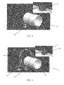
- Figure 4 shows an example of a preferred inspection system.
- an ultrasound transducer 10 is passed over the object 30 being inspected.
- the transducer 10 emits pulsed ultrasonic waves or electromagnetic waves that are imparted to the object 30.
- the waves pass into the object 30 and are reflected back by any interface or material anomaly, such as the back wall of the object 30 or from an imperfection within the object such as a crack, pit, eroded area, or a weld inclusion.
- the transducer 10 receives the reflected waves and sends the received data to connected diagnostic equipment 20, such as an oscilloscope.
- these results typically are displayed in the form of a signal with an amplitude representing the intensity of the reflection and the arrival time of the reflection representing the distance (depth) to the reflecting interface.
- the coils generating the electromagnetic waves are sensed for changes in impedance or magnetic field strength.
- Figure 4 depicts the tracking cameras 14 mounted to a tripod and positioned in an arch type configuration around the component 30 to be inspected. This configuration may also be adapted to provide for additional cameras 14 to encircle the entire circumference of the component 30 in order to provide a full 360° of tracking capability during the execution of the examination.
- the tripod mounting method depicted in Figure 4 may also be adapted to a belt or bracelet type configuration where the cameras are essential mounted directly to the component 30 under examination or remotely mounted by other means.
- the camera mounting method is not considered essential to this invention, provided a clear line of sight to the reference targets is maintained by two or more cameras 14 at any given point during the execution of the examination.
- the system is passed over or along the component 30 to be inspected in the same manner as would the transducer 10 if used alone.
- the transducer 10 emits and receives ultrasound data, which is provided to additional equipment 20 for processing and interpretation.
- the cameras 14 track the position of the reference targets 12 and relay that information to the host computer 25 where this information is converted into component surface coordinates and relayed to the NDE instrument to be used as trigger points to capture and record the examination data associated with that surface location on the component under examination.
- the system allows the operator to ensure that the entirety of the intended measurement area was in fact inspected and the data is recorded for future evaluation and permanent archiving.
- the position tracking and NDE data recording can be used to provide the system operator with real-time information related to the actual coverage of the intended scan area and adjustment can be made to assure complete coverage is obtained.
- One preferred manner of doing this is to change the image of the object on the operator's display, such as by changing the color of the object on the display as it is examined. In this manner, the operator could ensure that data has been collected for the entirety of the area intended to be inspected. By "coloring" the object on the display, the operator can know that the full inspection has been performed or if there are unexamined areas remaining for inspection.
- the inspection and position data are linked such that an area of the object will be shown as having been inspected if the transducer 10 was passed over that area and inspection data was received. If for some reason the transducer 10 was not operational or inspection data was not received when the transducer 10 was passed over the area, then it should not be shown as having been inspected.
- the inspection and position data can also be stored for later examination. This allows skilled personnel to review and interpret the data at a convenient time and location. This minimizes the time required for the inspection system to remain in the environs of the object under inspection, inherently reducing time and expense related to having the inspection equipment in place.
- the system thus allows fully encoded UT inspection data to be captured, stored, and displayed as though the scan was performed by an automated scanner without the setup difficulty or additional space required for a traditional automated scan system. Because the data is captured and stored, it may be analyzed and interpreted off-line in a comfortable environment. This allows the acquisition to be performed by relatively untrained inspectors, with the assurance that full measurements were made and subsequently the data may be interpreted by more highly qualified personnel.
- the system 1 can provide both absolute centroid position and transducer skew angle information. This provides assurance that the manual orientation of angle beam transducers is in fact aligned in accordance with the planned scan. Spacing of the cameras 14 is chosen in order to assure that a minimum of at least two cameras 14 can always view the reference targets throughout the full intended examination area.
- This invention applies optical tracking technology with an UT inspection system to associate encoded position data with the inspection data.
- the compact electronics of the optical tracking system can be positioned in relatively close proximity to the examination component and reference targets to be tracked can be attached to the UT transducer assembly to allow fully encoded position information to be associated with the UT data without substantially impacting the overall envelope of the UT transducer.
- the optical tracking system can be used to monitor skew or twist of the transducers with respect to the normal rectilinear transducer orientation.
- the transducer's position information is then coupled to the UT data to provide cross-sectional view of the inspected equipment and data maps (B and C scan data outputs) equivalent to fully encoded multi-axis manipulator automated scans, but with less setup burden and equipment expense.
- This two dimensional surface encoding approach can be registered with a three dimensional model of the inspection object to allow full use of three dimensional modeling data interpretation algorithms and three dimensional projections of any reflections observed while preserving the easy setup and data acquisition associated with traditional manual UT or alternate NDE examinations.
- ROVs remotely operated vehicles
- SAFT synthetic aperture focusing techniques
Applications Claiming Priority (1)
| Application Number | Priority Date | Filing Date | Title |
|---|---|---|---|
| US13/731,709 US20140184750A1 (en) | 2012-12-31 | 2012-12-31 | Stereo Vision Encoded Ultrasonic Inspection |
Publications (1)
| Publication Number | Publication Date |
|---|---|
| EP2749878A2 true EP2749878A2 (fr) | 2014-07-02 |
Family
ID=49765952
Family Applications (1)
| Application Number | Title | Priority Date | Filing Date |
|---|---|---|---|
| EP13197752.2A Withdrawn EP2749878A2 (fr) | 2012-12-31 | 2013-12-17 | Inspection ultrasonore codée de vision stéréo |
Country Status (2)
| Country | Link |
|---|---|
| US (1) | US20140184750A1 (fr) |
| EP (1) | EP2749878A2 (fr) |
Cited By (1)
| Publication number | Priority date | Publication date | Assignee | Title |
|---|---|---|---|---|
| CN110281235A (zh) * | 2019-06-05 | 2019-09-27 | 北京理工大学 | 基于参数可控的下位机数控程序的机械手上位机控制方法 |
Families Citing this family (3)
| Publication number | Priority date | Publication date | Assignee | Title |
|---|---|---|---|---|
| US10234269B2 (en) | 2015-06-11 | 2019-03-19 | Ge-Hitachi Nuclear Energy Americas Llc | Fiber optic shape sensing technology for encoding of NDE exams |
| US9678043B2 (en) | 2015-11-12 | 2017-06-13 | Bp Corporation North America Inc. | Methods, systems, and fixtures for inspection of gasket welds |
| JP7476057B2 (ja) * | 2020-09-11 | 2024-04-30 | キオクシア株式会社 | 欠陥検査装置 |
Family Cites Families (12)
| Publication number | Priority date | Publication date | Assignee | Title |
|---|---|---|---|---|
| US4078180A (en) * | 1976-03-17 | 1978-03-07 | United States Steel Corporation | X-ray inspection of welds |
| US4550376A (en) * | 1983-02-14 | 1985-10-29 | Maciejczak Robert A | Inspection system for mechanical structures |
| US4942614A (en) * | 1986-04-16 | 1990-07-17 | Australian Atomic Energy Commission | Calibration of ultrasonic transducers |
| US6211906B1 (en) * | 1995-09-07 | 2001-04-03 | Flight Landata, Inc. | Computerized component variable interference filter imaging spectrometer system method and apparatus |
| US6122967A (en) * | 1998-06-18 | 2000-09-26 | The United States Of America As Represented By The United States Department Of Energy | Free motion scanning system |
| US7795583B1 (en) * | 2005-10-07 | 2010-09-14 | The United States Of America As Represented By The Secretary Of The Navy | Long range active thermal imaging system and method |
| US7743660B2 (en) * | 2007-06-15 | 2010-06-29 | The Boeing Company | System and method for automated inspection of large-scale part |
| US20090003528A1 (en) * | 2007-06-19 | 2009-01-01 | Sankaralingam Ramraj | Target location by tracking of imaging device |
| US8044991B2 (en) * | 2007-09-28 | 2011-10-25 | The Boeing Company | Local positioning system and method |
| US20110177590A1 (en) * | 2009-12-11 | 2011-07-21 | Drexel University | Bioprinted Nanoparticles and Methods of Use |
| GB0921994D0 (en) * | 2009-12-17 | 2010-02-03 | Univ Gent | Methods and systems for optical characterisation |
| US9643313B2 (en) * | 2010-01-19 | 2017-05-09 | The Boeing Company | Apparatus for automated maintenance of aircraft structural elements |
-
2012
- 2012-12-31 US US13/731,709 patent/US20140184750A1/en not_active Abandoned
-
2013
- 2013-12-17 EP EP13197752.2A patent/EP2749878A2/fr not_active Withdrawn
Non-Patent Citations (1)
| Title |
|---|
| None |
Cited By (2)
| Publication number | Priority date | Publication date | Assignee | Title |
|---|---|---|---|---|
| CN110281235A (zh) * | 2019-06-05 | 2019-09-27 | 北京理工大学 | 基于参数可控的下位机数控程序的机械手上位机控制方法 |
| CN110281235B (zh) * | 2019-06-05 | 2020-10-02 | 北京理工大学 | 基于参数可控的下位机数控程序的机械手上位机控制方法 |
Also Published As
| Publication number | Publication date |
|---|---|
| US20140184750A1 (en) | 2014-07-03 |
Similar Documents
| Publication | Publication Date | Title |
|---|---|---|
| EP2749879A2 (fr) | Inspection non destructive codée optique | |
| US6925145B2 (en) | High speed digital radiographic inspection of piping | |
| US8616062B2 (en) | Ultrasonic inspection system and ultrasonic inspection method | |
| JP6224594B2 (ja) | 超音波マトリックス検査 | |
| US7334341B2 (en) | Measurement device | |
| US20080037695A1 (en) | Method and apparatus for ultrasonic inspection of reactor pressure vessel | |
| CN108414622A (zh) | 不锈钢管对接焊缝相控阵超声检测方法 | |
| US20120288049A1 (en) | Vibrothermographic Weld Inspections | |
| EP2749878A2 (fr) | Inspection ultrasonore codée de vision stéréo | |
| JP4111902B2 (ja) | 自動検査システム | |
| US20200034495A1 (en) | Systems, devices, and methods for generating a digital model of a structure | |
| Bulavinov et al. | Industrial application of real-time 3D imaging by sampling phased array | |
| JP2012247262A (ja) | 超音波探傷方法及び超音波探傷装置 | |
| US9625421B2 (en) | Manually operated small envelope scanner system | |
| Odakura et al. | Advanced inspection technologies for nuclear power plants | |
| KR100488366B1 (ko) | 초음파를 이용한 수소유기균열 및 부식 측정 시스템과안전성 평가 방법 | |
| Endo et al. | Signal evaluation system of flexible array ECT probes for inspecting complexly shaped surfaces | |
| JP2000249783A (ja) | 炉内配管溶接部の位置検出方法およびその装置 | |
| JP4676300B2 (ja) | Rt3次元サイジング装置 | |
| JP2019090740A (ja) | 放射線透視非破壊検査方法及び放射線透視非破壊検査装置 | |
| JP5422463B2 (ja) | 原子炉圧力容器下鏡部における非破壊検査手法 | |
| KR20210001379U (ko) | 협동 로봇을 이용한 초음파 탐상 검측 장치 | |
| Cinson et al. | Comparison of an ultrasonic phased array evaluation with destructive analysis of a documented leak path in a nozzle removed from service | |
| Bennecer | Reliability of manual ultrasonic testing | |
| Morozov et al. | Case Studies in Nondestructive Testing and Evaluation |
Legal Events
| Date | Code | Title | Description |
|---|---|---|---|
| 17P | Request for examination filed |
Effective date: 20131217 |
|
| AK | Designated contracting states |
Kind code of ref document: A2 Designated state(s): AL AT BE BG CH CY CZ DE DK EE ES FI FR GB GR HR HU IE IS IT LI LT LU LV MC MK MT NL NO PL PT RO RS SE SI SK SM TR |
|
| AX | Request for extension of the european patent |
Extension state: BA ME |
|
| PUAI | Public reference made under article 153(3) epc to a published international application that has entered the european phase |
Free format text: ORIGINAL CODE: 0009012 |
|
| RAP1 | Party data changed (applicant data changed or rights of an application transferred) |
Owner name: AREVA INC. |
|
| STAA | Information on the status of an ep patent application or granted ep patent |
Free format text: STATUS: THE APPLICATION IS DEEMED TO BE WITHDRAWN |
|
| 18D | Application deemed to be withdrawn |
Effective date: 20160701 |