EP2749871A1 - Rolling body examination method, rolling body manufacturing method, and rolling body - Google Patents
Rolling body examination method, rolling body manufacturing method, and rolling body Download PDFInfo
- Publication number
- EP2749871A1 EP2749871A1 EP12827264.8A EP12827264A EP2749871A1 EP 2749871 A1 EP2749871 A1 EP 2749871A1 EP 12827264 A EP12827264 A EP 12827264A EP 2749871 A1 EP2749871 A1 EP 2749871A1
- Authority
- EP
- European Patent Office
- Prior art keywords
- rolling element
- ray
- defect
- inspection
- light source
- Prior art date
- Legal status (The legal status is an assumption and is not a legal conclusion. Google has not performed a legal analysis and makes no representation as to the accuracy of the status listed.)
- Granted
Links
Images

Classifications
-
- G—PHYSICS
- G01—MEASURING; TESTING
- G01N—INVESTIGATING OR ANALYSING MATERIALS BY DETERMINING THEIR CHEMICAL OR PHYSICAL PROPERTIES
- G01N23/00—Investigating or analysing materials by the use of wave or particle radiation, e.g. X-rays or neutrons, not covered by groups G01N3/00 – G01N17/00, G01N21/00 or G01N22/00
- G01N23/02—Investigating or analysing materials by the use of wave or particle radiation, e.g. X-rays or neutrons, not covered by groups G01N3/00 – G01N17/00, G01N21/00 or G01N22/00 by transmitting the radiation through the material
- G01N23/04—Investigating or analysing materials by the use of wave or particle radiation, e.g. X-rays or neutrons, not covered by groups G01N3/00 – G01N17/00, G01N21/00 or G01N22/00 by transmitting the radiation through the material and forming images of the material
-
- F—MECHANICAL ENGINEERING; LIGHTING; HEATING; WEAPONS; BLASTING
- F16—ENGINEERING ELEMENTS AND UNITS; GENERAL MEASURES FOR PRODUCING AND MAINTAINING EFFECTIVE FUNCTIONING OF MACHINES OR INSTALLATIONS; THERMAL INSULATION IN GENERAL
- F16C—SHAFTS; FLEXIBLE SHAFTS; ELEMENTS OR CRANKSHAFT MECHANISMS; ROTARY BODIES OTHER THAN GEARING ELEMENTS; BEARINGS
- F16C33/00—Parts of bearings; Special methods for making bearings or parts thereof
- F16C33/30—Parts of ball or roller bearings
-
- G—PHYSICS
- G01—MEASURING; TESTING
- G01M—TESTING STATIC OR DYNAMIC BALANCE OF MACHINES OR STRUCTURES; TESTING OF STRUCTURES OR APPARATUS, NOT OTHERWISE PROVIDED FOR
- G01M13/00—Testing of machine parts
- G01M13/04—Bearings
-
- G—PHYSICS
- G01—MEASURING; TESTING
- G01N—INVESTIGATING OR ANALYSING MATERIALS BY DETERMINING THEIR CHEMICAL OR PHYSICAL PROPERTIES
- G01N2223/00—Investigating materials by wave or particle radiation
- G01N2223/60—Specific applications or type of materials
- G01N2223/646—Specific applications or type of materials flaws, defects
-
- G—PHYSICS
- G01—MEASURING; TESTING
- G01N—INVESTIGATING OR ANALYSING MATERIALS BY DETERMINING THEIR CHEMICAL OR PHYSICAL PROPERTIES
- G01N23/00—Investigating or analysing materials by the use of wave or particle radiation, e.g. X-rays or neutrons, not covered by groups G01N3/00 – G01N17/00, G01N21/00 or G01N22/00
- G01N23/02—Investigating or analysing materials by the use of wave or particle radiation, e.g. X-rays or neutrons, not covered by groups G01N3/00 – G01N17/00, G01N21/00 or G01N22/00 by transmitting the radiation through the material
- G01N23/06—Investigating or analysing materials by the use of wave or particle radiation, e.g. X-rays or neutrons, not covered by groups G01N3/00 – G01N17/00, G01N21/00 or G01N22/00 by transmitting the radiation through the material and measuring the absorption
- G01N23/083—Investigating or analysing materials by the use of wave or particle radiation, e.g. X-rays or neutrons, not covered by groups G01N3/00 – G01N17/00, G01N21/00 or G01N22/00 by transmitting the radiation through the material and measuring the absorption the radiation being X-rays
Definitions
- the present invention relates to a rolling element inspection method, a rolling element manufacturing method, and a rolling element. More particularly, the present invention relates to a method of inspecting a rolling element made of ceramics, used as a rolling element of a rolling bearing, for example, a method of manufacturing the rolling element, and the rolling element.
- the size of the defect to be detected is generally greater than or equal to 20 ⁇ m, depending upon the material strength and the like.
- a scratch on the surface of the rolling element, a defect in the inclusion and the like may be detected by an appearance inspection through visual confirmation, the method of inspecting the reflected state of light from the surface of a rolling element using an optical system, and the like. Since the time required for such inspection is short according to these methods, they can be employed in mass production processes.
- the durability may be degraded even in the case where there is a defect, not only at the surface, but also inside. Therefore, the inspection for a defect must be performed for the entire interior in addition to the surface of the rolling element.
- an object of the present invention is to provide a rolling element inspection method allowing a rolling element made of ceramics to be inspected entirely without omission and in a short period of time, a rolling element manufacturing method employing the inspection method, and a rolling element manufactured by the manufacturing method.
- a rolling element inspection method of the present invention is directed to a method of inspecting a rolling element made of ceramics.
- the inspection method includes the steps of projecting an X-ray from a light source to a rolling element, detecting the X-ray passing through the rolling element, calculating data of the detected X-ray to generate an image, and detecting a defect in the rolling element based on the image.
- the light source rotates relatively around the rolling element while an X-ray is projected to an entire region of the rolling element facing the light source.
- the data of the X-ray for one circuit around the rolling element is calculated to generate an image.
- the light source rotates relatively around a rolling element while an X-ray is projected to an entire region of the rolling element facing the light source, and data of the X-ray for one circuit around the rolling element is calculated to generate an image. Therefore, the entirety of the rolling element made of ceramics can be inspected without omission, differing from the case where images picked up at a predetermined distance are integrated. Moreover, since an image is generated based on data of the X-ray for one circuit around the rolling element, the inspection can be performed in a short period of time, differing from the case where images for the integration processing are picked up over a significant period of time. Thus, according to the rolling element inspection method of the present invention, a rolling element made of ceramics can be inspected entirely without omission and in a short period of time.
- an X-ray may be projected from a light source having a focal point size less than or equal to 10 ⁇ m.
- a minute defect for example a defect having a size of approximately 20 ⁇ m, can be readily detected.
- an X-ray spreading conically from the light source may be projected to the rolling element. Accordingly, the entire region of the rolling element facing the light source can be readily irradiated with an X-ray. Particularly in the case where the focal point size of the light source is reduced down to less than or equal to 10 ⁇ m, the entire region of the rolling element facing the light source can be readily irradiated with an X-ray by projecting the X-ray to the rolling element so as to spread conically.
- the ceramics may have silicon nitride or sialon as the main component.
- the rolling element inspection method of the present invention is suitable to the inspection of a rolling element formed of ceramics with silicon nitride or sialon as the main component
- an internal defect may be detected in the step of detecting a defect.
- the rolling element inspection method of the present invention an X-ray passing through a rolling element is detected to implement the inspection. Therefore, the rolling element inspection method of the present invention is suitable for detecting an internal defect that is difficult to be detected in the aforementioned appearance inspection by visual confirmation.
- a defect having a size of at least 20 ⁇ m may be detected. Accordingly, sufficient accuracy can be ensured for a method of inspecting a rolling element made of ceramics.
- the defect detected in the step of detecting a defect may be a metal inclusion or a hole.
- the metal inclusion or hole may have a serious effect on the durability and the like of a rolling element made of ceramics. By detecting such defects, an inspection allowing the reliability of the rolling element to be further improved can be implemented.
- a rolling element manufacturing method includes the steps of producing a rolling element made of ceramics, and inspecting the rolling element. In the step of inspecting the rolling element, the rolling element is inspected by the above-described rolling element inspection method of the present invention.
- the rolling element manufacturing method of the present invention allows a highly-reliable rolling element made of ceramics to be manufactured efficiently.
- a rolling element according to the present invention is manufactured by the above-described rolling element manufacturing method of the present invention.
- the rolling element of the present invention there can be provided a rolling element made of ceramics, highly-reliable and having the production cost suppressed by the efficient manufacturing.
- a rolling element inspection method that allows a rolling element made of ceramics to be inspected entirely without omission and in a short period of time, a rolling element manufacturing method employing the inspection method, and a rolling element manufactured by the manufacturing method.
- a raw material powder preparation step is executed as step S10.
- raw material powder such as silicon nitride, sialon, and the like is prepared.
- step S20 a mixing step is executed as step S20.
- a sintering agent prepared separately is added and mixed with the raw material powder prepared at, for example, step S10.
- a rolling element is to be manufactured by mixing a plurality of types of raw material powder
- such raw material powder can be mixed at this step S20.
- step S20 can be omitted.
- a shaping step is executed as step S30.
- the above-described raw material powder, a mixture of raw material powder, or a mixture of raw material powder and sintering agent is shaped to a substantial form of a rolling element.
- a shaping method such as press-forming, casting, extrusion molding, granulation, and the like to the powder, a compact shaped to substantially the form of a rolling element such as a ball or roller can be produced.
- step S40 a sintering step is executed as step S40.
- the compact is sintered to produce a sintered compact.
- This step S40 may be executed by employing pressure sintering such as hot press (HP) and hot isostatic press (HIP), or by pressureless sintering.
- pressure sintering such as hot press (HP) and hot isostatic press (HIP)
- pressureless sintering for the aforementioned sintering heating method, electromagnetic wave heating such as by microwaves or millimeter waves may be employed in addition to heating using a heater.
- step S50 a finishing step is executed as step S50.
- the surface of the sintered compact produced at step S40 is worked to execute a finishing process in which a region including the surface is removed.
- a ceramics rolling element is completed.
- step S60 an inspection step is executed as step S60.
- step S60 the above-described ceramics rolling element is inspected by a rolling element inspection method according to the present embodiment that will be described hereinafter.
- an inspection device 1 of the present embodiment corresponding to X-ray CT includes a holder 11 for holding a rolling element 91 such as a ball or roller, a light source 12 for projecting an X-ray 99 to rolling element 91 held by holder 11, and a detector 13 arranged at a side opposite to light source 12 about rolling element 91 held by holder 11, and detecting an X-ray passing through rolling element 91.
- a semiconductor flat panel detector for example, may be employed.
- Light source 12 and detector 13 can rotate about rolling element 91 held by holder 11 while maintaining a positional relationship relative to each other, as shown in Fig. 3 .
- Inspection device 1 further includes a calculation unit 14 connected to detector 13 for calculating data of an X-ray detected by detector 13, an image formation unit 15 connected to calculation unit 14 for forming an image based on the calculated result at calculation unit 14, and a defect detector 16 connected to image formation unit 14 for detecting a defect in rolling element 91 based on the formed image.
- a calculation unit 14 connected to detector 13 for calculating data of an X-ray detected by detector 13, an image formation unit 15 connected to calculation unit 14 for forming an image based on the calculated result at calculation unit 14, and a defect detector 16 connected to image formation unit 14 for detecting a defect in rolling element 91 based on the formed image.
- rolling element 91 that is the subject of inspection is set at holder 11.
- an element with ceramics as the main component formed of atoms of low atomic number and light in weight such as silicon nitride or sialon can be employed.
- X-ray 99 is projected from light source 12 to rolling element 91 held by holder 11.
- the entirety of the region of rolling element 91 facing light source 12 is irradiated with X-ray 99, as shown in Figs. 2 and 3 .
- the projected X-ray 99 passes through rolling element 91 to be detected by detector 13.
- Projection of X-ray 99 from light source 12 and detection of X-ray 99 by detector 13 are implemented while the positional relationship between light source 12 and detector 13 is maintained by light source 12 rotating along arrow ⁇ about rolling element 91, as shown in Fig. 3 , and detector 13 rotating along arrow ⁇ .
- data of X-ray 99 detected by detector 13 is calculated at calculation unit 14. Based on the calculated result, an image is formed at image formation unit 15. This image is generated by the calculation of data of X-ray 99 for one circuit around rolling element 91.
- a defect in rolling element 91 for example an internal defect such as a metal inclusion and/or hole, is detected by defect detector 16.
- the size of the detected defect is preferably to the smallest possible degree, a defect having a size of at least 20 ⁇ m is preferably detected.
- light source 12 rotates relative to and around rolling element 91 while X-ray 99 is projected to the entire region of rolling element 91 facing light source 12, and data of the X-ray 99 for one circuit around rolling element 91, i.e. for 360° around rolling element 91, is calculated to generate an image. Therefore, the entirety of rolling element 91 can be inspected without omission, differing from the case where images picked up at a predetermined distance are integrated. Furthermore, since an image is generated based on data of X-ray 99 for one circuit around rolling element 91, inspection can be carried out in a short period of time, differing from the case where images for the integration processing are picked up over a significant period of time.
- the entirety of rolling element 91 can be inspected without omission and in a short period of time.
- the inspection step can be implemented efficiently and accurately. Therefore, a rolling element 91 of high reliability can be manufactured economically. Since rolling element 91 obtained by the above-described inspection step is confirmed to be absent of a defect of at least a predetermined size, for example a defect of at least 20 ⁇ m in size, a rolling element of high reliability can be achieved.
- the micro X-ray CT directed to experimental animals was employed.
- a silicon nitride ceramic ball and a sialon ceramic ball (diameter 3/8 inches) having an internal defect (metal inclusion, hole) were inspected for an inspection time of 17 seconds. From the obtained 3D image data, the position of the defect was identified. Then, the ceramic ball was cut at the identified site for observation of the cross section. For comparison, a similar inspection was carried out for a steel ball (made of JIS SUJ2) of the same size. The results of the experiments are shown in Tables 1 and 2.
- Table 1 Type of Internal Defect Inspection Time Metal Inclusion (silicon nitride, sialon) Non-Metal Inclusion (steel material) Hole 20 ⁇ m 30 ⁇ m 20 ⁇ m 30 ⁇ m Material Silicon Nitride Detectable Detectable Detectable 17 sec. Sialon Detectable Detectable Detectable 17 sec. Steel Material (SUJ2) Non-detectable Non-detectable Non-detectable Non-detectable 17 sec.
- metal inclusions and holes of 20 ⁇ m and 30 ⁇ m in size were detected by an inspection time of 17 seconds.
- an X-ray could not pass through.
- An internal defect could not be detected regardless of the size of the defect.
- the rolling element inspection method, rolling element manufacturing method, and rolling element of the present invention can be advantageously applied particularly to an inspection method of a rolling element made of ceramics employed as a rolling element for a rolling bearing, a rolling element manufacturing method, and a rolling element.
Landscapes
- Physics & Mathematics (AREA)
- General Physics & Mathematics (AREA)
- General Engineering & Computer Science (AREA)
- Engineering & Computer Science (AREA)
- Biochemistry (AREA)
- Analytical Chemistry (AREA)
- Chemical & Material Sciences (AREA)
- General Health & Medical Sciences (AREA)
- Immunology (AREA)
- Pathology (AREA)
- Life Sciences & Earth Sciences (AREA)
- Health & Medical Sciences (AREA)
- Mechanical Engineering (AREA)
- Analysing Materials By The Use Of Radiation (AREA)
- Rolling Contact Bearings (AREA)
Abstract
Description
- The present invention relates to a rolling element inspection method, a rolling element manufacturing method, and a rolling element. More particularly, the present invention relates to a method of inspecting a rolling element made of ceramics, used as a rolling element of a rolling bearing, for example, a method of manufacturing the rolling element, and the rolling element.
- In recent years, the need arises for a shaft such as the main spindle of a working machine to exhibit higher rotation and higher accuracy. There is a growing demand for a rolling element made of ceramics that is light and highly tough as a rolling element of a rolling bearing that supports such a shaft. A rolling element made of ceramics has high insulation. Therefore, the potential of a rolling element of a bearing for use in power generators and motors is high. There is also the potential for use in transportation machines such as aircrafts and automobiles by virtue of its lightweight property as compared to a steel ball that is the general rolling element of a bearing.
- By the demand of high reliability in rolling bearings, 100% inspection is required in the manufacturing of rolling elements made of ceramics to detect any defect in the material and work. The size of the defect to be detected is generally greater than or equal to 20 µm, depending upon the material strength and the like.
- A scratch on the surface of the rolling element, a defect in the inclusion and the like may be detected by an appearance inspection through visual confirmation, the method of inspecting the reflected state of light from the surface of a rolling element using an optical system, and the like. Since the time required for such inspection is short according to these methods, they can be employed in mass production processes.
- However, in rolling elements made of ceramics, the durability may be degraded even in the case where there is a defect, not only at the surface, but also inside. Therefore, the inspection for a defect must be performed for the entire interior in addition to the surface of the rolling element.
- As a method of detecting a defect present inside a component made of ceramics, there is proposed a method including the steps of applying integration processing on an image obtained by X-ray transmission, and differentiating the integration-processed image to detect an internal defect (for example, refer to Japanese Patent Laying-Open No.
8-146137 - There is also known a method of evaluating the porosity distribution of silicon nitride sintered body using X-ray CT (Computed Tomography) (for example, refer to Japanese Patent Laying-Open No.
2001-241465 - There is additionally known a method of measuring the porosity distribution in a ceramic structure by driving an X-ray source and a detector helically in a scanning operation using medical X-ray CT (for example, refer to Japanese Patent Laying-Open No.
2005-283547 -
- PTD 1: Japanese Patent Laying-Open No.
8-146137 - PTD 2: Japanese Patent Laying-Open No.
2001-201465 - PTD 3: Japanese Patent Laying-Open No.
2005-283547 - Although various types of methods are proposed for inspecting an internal defect (for example, an inclusion, hole, and the like) in a structure made of ceramics as set forth above, they have problems such as the inspection is too time-consuming, the entirety of the interior of the structure cannot be inspected without omission, and the like. They are insufficient for the method of inspecting a rolling element made of ceramics.
- In view of the foregoing, an object of the present invention is to provide a rolling element inspection method allowing a rolling element made of ceramics to be inspected entirely without omission and in a short period of time, a rolling element manufacturing method employing the inspection method, and a rolling element manufactured by the manufacturing method.
- A rolling element inspection method of the present invention is directed to a method of inspecting a rolling element made of ceramics. The inspection method includes the steps of projecting an X-ray from a light source to a rolling element, detecting the X-ray passing through the rolling element, calculating data of the detected X-ray to generate an image, and detecting a defect in the rolling element based on the image. At the step of projecting an X-ray, the light source rotates relatively around the rolling element while an X-ray is projected to an entire region of the rolling element facing the light source. At the step of generating an image, the data of the X-ray for one circuit around the rolling element is calculated to generate an image.
- In the rolling element inspection method of the present invention, the light source rotates relatively around a rolling element while an X-ray is projected to an entire region of the rolling element facing the light source, and data of the X-ray for one circuit around the rolling element is calculated to generate an image. Therefore, the entirety of the rolling element made of ceramics can be inspected without omission, differing from the case where images picked up at a predetermined distance are integrated. Moreover, since an image is generated based on data of the X-ray for one circuit around the rolling element, the inspection can be performed in a short period of time, differing from the case where images for the integration processing are picked up over a significant period of time. Thus, according to the rolling element inspection method of the present invention, a rolling element made of ceramics can be inspected entirely without omission and in a short period of time.
- In the step of projecting an X-ray in the rolling element inspection method set forth above, an X-ray may be projected from a light source having a focal point size less than or equal to 10 µm.
- Accordingly, blurring is reduced even if the rolling element approaches the focal point of the light source, allowing high resolution to be obtained. As a result, a minute defect, for example a defect having a size of approximately 20 µm, can be readily detected.
- In the step of projecting an X-ray in the rolling element inspection method set forth above, an X-ray spreading conically from the light source may be projected to the rolling element. Accordingly, the entire region of the rolling element facing the light source can be readily irradiated with an X-ray. Particularly in the case where the focal point size of the light source is reduced down to less than or equal to 10 µm, the entire region of the rolling element facing the light source can be readily irradiated with an X-ray by projecting the X-ray to the rolling element so as to spread conically.
- In the rolling element inspection method set forth above, the ceramics may have silicon nitride or sialon as the main component.
- For a rolling element having ceramics formed of atoms of low atomic number such as silicon nitride or sialon as the main component, internal inspection by transmitting an X-ray is facilitated. Therefore, the rolling element inspection method of the present invention is suitable to the inspection of a rolling element formed of ceramics with silicon nitride or sialon as the main component
- In the rolling element inspection method set forth above, an internal defect may be detected in the step of detecting a defect.
- In the rolling element inspection method of the present invention, an X-ray passing through a rolling element is detected to implement the inspection. Therefore, the rolling element inspection method of the present invention is suitable for detecting an internal defect that is difficult to be detected in the aforementioned appearance inspection by visual confirmation.
- In the step of detecting a defect in the rolling element inspection method set forth above, a defect having a size of at least 20 µm may be detected. Accordingly, sufficient accuracy can be ensured for a method of inspecting a rolling element made of ceramics.
- In the rolling element inspection method set forth above, the defect detected in the step of detecting a defect may be a metal inclusion or a hole.
- The metal inclusion or hole may have a serious effect on the durability and the like of a rolling element made of ceramics. By detecting such defects, an inspection allowing the reliability of the rolling element to be further improved can be implemented.
- A rolling element manufacturing method according to the present invention includes the steps of producing a rolling element made of ceramics, and inspecting the rolling element. In the step of inspecting the rolling element, the rolling element is inspected by the above-described rolling element inspection method of the present invention.
- By employing a rolling element inspection method of the present invention allowing a rolling element to be inspected entirely without omission and in a short period of time, the rolling element manufacturing method of the present invention allows a highly-reliable rolling element made of ceramics to be manufactured efficiently.
- A rolling element according to the present invention is manufactured by the above-described rolling element manufacturing method of the present invention. By the rolling element of the present invention, there can be provided a rolling element made of ceramics, highly-reliable and having the production cost suppressed by the efficient manufacturing.
- According to a rolling element inspection method, a rolling element manufacturing method, and a rolling element of the present invention, there can be provided a rolling element inspection method that allows a rolling element made of ceramics to be inspected entirely without omission and in a short period of time, a rolling element manufacturing method employing the inspection method, and a rolling element manufactured by the manufacturing method.
-
-
Fig. 1 is a flowchart schematically representing a manufacturing method of a rolling element made of ceramics. -
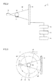
Fig. 2 is a schematic diagram of a configuration of a device to implement a rolling element inspection method of the present invention. -
Fig. 3 is a diagram to describe an operation of a light source and a detector. - Embodiments of the present invention will be described hereinafter based on the drawings. In the drawings, the same or corresponding elements have the same reference characters allotted, and description thereof will not be repeated.
- In a rolling element manufacturing method according to an embodiment of the present invention with reference to
Fig. 1 , a raw material powder preparation step is executed as step S10. At step S10, raw material powder such as silicon nitride, sialon, and the like is prepared. - Then, a mixing step is executed as step S20. At step S20, a sintering agent prepared separately is added and mixed with the raw material powder prepared at, for example, step S10. In the case where a rolling element is to be manufactured by mixing a plurality of types of raw material powder, such raw material powder can be mixed at this step S20. In the case where a sintering agent is not employed and a rolling element is to be manufactured from one type of raw material powder, step S20 can be omitted.
- Then, a shaping step is executed as step S30. At step S30, the above-described raw material powder, a mixture of raw material powder, or a mixture of raw material powder and sintering agent is shaped to a substantial form of a rolling element. Specifically, by applying a shaping method such as press-forming, casting, extrusion molding, granulation, and the like to the powder, a compact shaped to substantially the form of a rolling element such as a ball or roller can be produced.
- Then, a sintering step is executed as step S40. At step S40, the compact is sintered to produce a sintered compact. This step S40 may be executed by employing pressure sintering such as hot press (HP) and hot isostatic press (HIP), or by pressureless sintering. For the aforementioned sintering heating method, electromagnetic wave heating such as by microwaves or millimeter waves may be employed in addition to heating using a heater.
- Then, a finishing step is executed as step S50. At step S50, the surface of the sintered compact produced at step S40 is worked to execute a finishing process in which a region including the surface is removed. Thus, a ceramics rolling element is completed.
- Then, an inspection step is executed as step S60. At step S60, the above-described ceramics rolling element is inspected by a rolling element inspection method according to the present embodiment that will be described hereinafter.
- First, an inspection device employed in the rolling element inspection method of the present embodiment will be described with reference to
Figs. 2 and 3. Fig. 2 is a sectional view including the rotation axis of the light source, whereasFig. 3 is a sectional view perpendicular to the rotation axis of the light source. Referring toFig. 2 , an inspection device 1 of the present embodiment corresponding to X-ray CT includes aholder 11 for holding a rollingelement 91 such as a ball or roller, alight source 12 for projecting anX-ray 99 to rollingelement 91 held byholder 11, and adetector 13 arranged at a side opposite tolight source 12 about rollingelement 91 held byholder 11, and detecting an X-ray passing through rollingelement 91. Fordetector 13, a semiconductor flat panel detector, for example, may be employed.Light source 12 anddetector 13 can rotate about rollingelement 91 held byholder 11 while maintaining a positional relationship relative to each other, as shown inFig. 3 . - Inspection device 1 further includes a
calculation unit 14 connected todetector 13 for calculating data of an X-ray detected bydetector 13, animage formation unit 15 connected tocalculation unit 14 for forming an image based on the calculated result atcalculation unit 14, and adefect detector 16 connected to imageformation unit 14 for detecting a defect in rollingelement 91 based on the formed image. - Next, an inspection method of rolling
element 91 according to the present embodiment using inspection device 1 set forth above will be described hereinafter. In the inspection method of the present embodiment with reference toFigs. 2 and 3 , first, rollingelement 91 that is the subject of inspection is set atholder 11. For rollingelement 91, an element with ceramics as the main component, formed of atoms of low atomic number and light in weight such as silicon nitride or sialon can be employed. - Next,
X-ray 99 is projected fromlight source 12 to rollingelement 91 held byholder 11. At this stage, the entirety of the region of rollingelement 91 facinglight source 12 is irradiated withX-ray 99, as shown inFigs. 2 and 3 . The projectedX-ray 99 passes through rollingelement 91 to be detected bydetector 13. Projection ofX-ray 99 fromlight source 12 and detection ofX-ray 99 bydetector 13 are implemented while the positional relationship betweenlight source 12 anddetector 13 is maintained bylight source 12 rotating along arrow α about rollingelement 91, as shown inFig. 3 , anddetector 13 rotating along arrow β. - Referring to
Fig. 2 , data ofX-ray 99 detected bydetector 13 is calculated atcalculation unit 14. Based on the calculated result, an image is formed atimage formation unit 15. This image is generated by the calculation of data ofX-ray 99 for one circuit around rollingelement 91. - Based on the formed image, a defect in rolling
element 91, for example an internal defect such as a metal inclusion and/or hole, is detected bydefect detector 16. Although the size of the detected defect is preferably to the smallest possible degree, a defect having a size of at least 20 µm is preferably detected. In order to achieve such high detection sensitivity, preferably the method of performing X-ray projection and detection using a micro focus X-ray source forlight source 12, having the focal point size less than or equal to 10 µm, specifically approximately 5 µm, usingX-ray 99 spreading conically fromlight source 12, i.e. volume measurement by the so-called cone beam scanning, is implemented. - In the inspection method of rolling
element 91 of the present embodiment,light source 12 rotates relative to and around rollingelement 91 whileX-ray 99 is projected to the entire region of rollingelement 91 facinglight source 12, and data of theX-ray 99 for one circuit around rollingelement 91, i.e. for 360° around rollingelement 91, is calculated to generate an image. Therefore, the entirety of rollingelement 91 can be inspected without omission, differing from the case where images picked up at a predetermined distance are integrated. Furthermore, since an image is generated based on data ofX-ray 99 for one circuit around rollingelement 91, inspection can be carried out in a short period of time, differing from the case where images for the integration processing are picked up over a significant period of time. According to the inspection method of rollingelement 91 of the present embodiment, the entirety of rollingelement 91 can be inspected without omission and in a short period of time. As a result, in the manufacturing method of rollingelement 91 of the present embodiment incorporating the above-described inspection method for the inspection step, the inspection step can be implemented efficiently and accurately. Therefore, a rollingelement 91 of high reliability can be manufactured economically. Since rollingelement 91 obtained by the above-described inspection step is confirmed to be absent of a defect of at least a predetermined size, for example a defect of at least 20 µm in size, a rolling element of high reliability can be achieved. - By a rolling element inspection method of the present invention, a ceramic ball employed as a rolling element made of ceramic was inspected for an internal defect. Experiments to examine the sensitivity, accuracy, and the like were carried out. The procedures of the experiments are set forth below.
- For an inspection device, the micro X-ray CT directed to experimental animals (Rigaku Corporation) was employed. By a method similar to that of the above-described embodiment, a silicon nitride ceramic ball and a sialon ceramic ball (diameter 3/8 inches) having an internal defect (metal inclusion, hole) were inspected for an inspection time of 17 seconds. From the obtained 3D image data, the position of the defect was identified. Then, the ceramic ball was cut at the identified site for observation of the cross section. For comparison, a similar inspection was carried out for a steel ball (made of JIS SUJ2) of the same size. The results of the experiments are shown in Tables 1 and 2.
Table 1 Type of Internal Defect Inspection Time Metal Inclusion (silicon nitride, sialon) Non-Metal Inclusion (steel material) Hole 20 µm 30 µm 20 µm 30 µm Material Silicon Nitride Detectable Detectable Detectable Detectable 17 sec. Sialon Detectable Detectable Detectable Detectable 17 sec. Steel Material (SUJ2) Non-detectable Non-detectable Non-detectable Non-detectable 17 sec. Table 2 Site (from top) From surface layer (lateral) Size Width Length Depth Experimental animal X-ray CT Approximately 1.9 mm 400 µm Approximately 150 µm Cut, Actual Measurement Approximately 1.8 mm 414 µm Approximately 114 µm Approximately 138 µm Approximately 80 µm - For the silicon nitride ceramics ball and sialon ceramics ball shown in Table 1, metal inclusions and holes of 20 µm and 30 µm in size were detected by an inspection time of 17 seconds. For the steel ball, an X-ray could not pass through. An internal defect could not be detected regardless of the size of the defect.
- By comparing the information about the location and size of the defects detected by X-ray CT, and the information about the location and size of the defects by actually cutting the ceramic ball and actually measuring the defect shown in Table 2, it was confirmed that accuracy sufficiently applicable to the inspection of a rolling element for both the location and size was achieved.
- For comparison, trials were conducted to detect a defect in a silicon nitride ceramic ball (diameter 3/8 inches) using various inspection methods such as the step type X-ray CT for industrial usage, X-ray transmission inspection by subtraction techniques, inspection by non-linear ultrasonic wave, and inspection by medical X-ray CT. The results of the experiments are shown in Table 3.
Table 3 Inspection Method Detectable or Not Inspection Time Industrial (step type) X-ray CT Detectable 80 minutes X-ray Transmission Inspection by Difference Processing Detectable 3 hours Non-linear Ultrasonic Wave Non-detectable - Medical X-ray CT Non-detectable 40 seconds - It is appreciated from Table 3 that although a defect could be detected according to the industrial step type X-ray CT inspection and X-ray transmission inspection by difference processing, the inspection time took 80 minutes and 3 hours, respectively, which is time-consuming. In the inspection by non-linear ultrasonic waves, the setting of the inspection conditions such as the way of applying the ultrasonic wave was difficult. A defect could not be detected. The inspection by medical X-ray CT took 40 seconds for the inspection time. However, a defect could not be detected since the slicing distance was 0.5 mm.
- It was confirmed by the results of the experiments set forth above that the inspection method of a rolling element made of ceramics of the present invention allowed the entirety of a rolling element made of ceramics to be inspected without omission and in a short period of time, which was difficult to realize by conventional inspection methods.
- It should be understood that the embodiments and examples disclosed herein are illustrative and non-restrictive in every respect. The scope of the present invention is defined by the terms of the claims, rather than the description above, and is intended to include any modification within the scope and meaning equivalent to the terms of the claims.
- The rolling element inspection method, rolling element manufacturing method, and rolling element of the present invention can be advantageously applied particularly to an inspection method of a rolling element made of ceramics employed as a rolling element for a rolling bearing, a rolling element manufacturing method, and a rolling element.
- 1 inspection device, 11 holder, 12 light source, 13 detector, 14 calculation unit, 15 image formation unit, 16 defect detector, 91 rolling element, 99 X-ray.
Claims (9)
- An inspection method of a rolling element (91) made of ceramics, comprising the steps of:projecting an X-ray (99) from a light source (12) to said rolling element (91),detecting said X-ray (99) passing through said rolling element (91),calculating data of said detected X-ray (99) to generate an image, anddetecting a defect in said rolling element (91) based on said image,at said step of projecting an X-ray (99), said light source (12) being rotated relatively around said rolling element (91) while said X-ray (99) is projected to an entire region of said rolling element (91) facing said light source (12),at said step of generating an image, data of said X-ray (99) for one circuit around said rolling element (91) being calculated to generate said image.
- The inspection method of a rolling element (91) according to claim 1, wherein said X-ray (99) is projected from said light source (12) having a focal point size less than or equal to 10 µm, at said step of projecting an X-ray (99).
- The inspection method of a rolling element (91) according to claim 1, wherein said X-ray (99) spreading conically from said light source (12) is projected to said rolling element (91), at said step of projecting an X-ray (99).
- The inspection method of a rolling element (91) according to claim 1, wherein said ceramics has silicon nitride or sialon as a main component.
- The inspection method of a rolling element (91) according to claim 1, wherein an internal defect is detected at said step of detecting a defect.
- The inspection method of a rolling element (91) according to claim 1, wherein a defect of at least 20 µm in size is detected at said step of detecting a defect.
- The inspection method of a rolling element (91) according to claim 1, wherein a defect detected at said step of detecting a defect is a metal inclusion or a hole.
- A manufacturing method of a rolling element (91) comprising the steps of:producing a rolling element (91) made of ceramics, andinspecting said rolling element (91),said rolling element (91) being inspected by the inspection method of a rolling element (91) defined in claim 1, at said step of inspecting a rolling element (91).
- A rolling element (91) manufactured by the manufacturing method of a rolling element (91) defined in claim 8.
Applications Claiming Priority (2)
| Application Number | Priority Date | Filing Date | Title |
|---|---|---|---|
| JP2011184878A JP5922892B2 (en) | 2011-08-26 | 2011-08-26 | Rolling body inspection method and rolling body manufacturing method |
| PCT/JP2012/069155 WO2013031450A1 (en) | 2011-08-26 | 2012-07-27 | Rolling body examination method, rolling body manufacturing method, and rolling body |
Publications (3)
| Publication Number | Publication Date |
|---|---|
| EP2749871A1 true EP2749871A1 (en) | 2014-07-02 |
| EP2749871A4 EP2749871A4 (en) | 2015-04-01 |
| EP2749871B1 EP2749871B1 (en) | 2018-01-31 |
Family
ID=47755953
Family Applications (1)
| Application Number | Title | Priority Date | Filing Date |
|---|---|---|---|
| EP12827264.8A Not-in-force EP2749871B1 (en) | 2011-08-26 | 2012-07-27 | Rolling body examination method and rolling body manufacturing method |
Country Status (4)
| Country | Link |
|---|---|
| US (1) | US10048214B2 (en) |
| EP (1) | EP2749871B1 (en) |
| JP (1) | JP5922892B2 (en) |
| WO (1) | WO2013031450A1 (en) |
Cited By (1)
| Publication number | Priority date | Publication date | Assignee | Title |
|---|---|---|---|---|
| GB2596181A (en) * | 2020-06-18 | 2021-12-22 | Skf Ab | Method for detecting a critical defect in a ceramic folling element |
Families Citing this family (4)
| Publication number | Priority date | Publication date | Assignee | Title |
|---|---|---|---|---|
| CN101583804B (en) | 2006-12-20 | 2012-07-11 | Ntn株式会社 | Rolling bearing, hub unit, rolling member, universal joint, torque transmission member for universal joint, and manufacturing method thereof |
| EP2163775B1 (en) * | 2007-06-27 | 2014-09-03 | NTN Corporation | Rolling member, rolling bearing and process for manufacturing rolling member |
| JP7003346B2 (en) * | 2017-06-23 | 2022-01-20 | 株式会社ニッカトー | Ceramic sphere inspection device |
| CN114295653B (en) * | 2021-11-30 | 2023-12-22 | 太仓市林源电线电缆有限公司 | Multi-section type online continuous detection method for electrical copper wire |
Family Cites Families (20)
| Publication number | Priority date | Publication date | Assignee | Title |
|---|---|---|---|---|
| US4149247A (en) * | 1975-12-23 | 1979-04-10 | Varian Associates, Inc. | Tomographic apparatus and method for reconstructing planar slices from non-absorbed and non-scattered radiation |
| US4672650A (en) * | 1984-02-16 | 1987-06-09 | Kabushiki Kaisha Toshiba | Tomographic testing apparatus |
| JP3202311B2 (en) * | 1992-04-03 | 2001-08-27 | 株式会社東芝 | Defect inspection method for bearing parts |
| JPH05322802A (en) * | 1992-05-20 | 1993-12-07 | Nippon Steel Corp | X-ray CT system |
| JPH05332802A (en) * | 1992-05-28 | 1993-12-17 | Masaharu Yamamoto | Measuring method for passing amount (moving amount) of powder, particles and blocks |
| US5473655A (en) * | 1994-07-21 | 1995-12-05 | General Electric Company | Artifact reduction by z-dependent filtration of three-dimensional cone beam data |
| JP3545073B2 (en) | 1994-11-25 | 2004-07-21 | 財団法人ファインセラミックスセンター | Radioscopy using difference image processing |
| JP3631652B2 (en) | 2000-01-20 | 2005-03-23 | 日本碍子株式会社 | Non-destructive inspection method using X-ray |
| US6341153B1 (en) * | 2000-10-27 | 2002-01-22 | Genesis Engineering Company | System and method for portable nondestructive examination with realtime three-dimensional tomography |
| JP2002243662A (en) * | 2001-02-09 | 2002-08-28 | Toyota Motor Corp | X-ray CT system |
| JP2005283547A (en) | 2004-03-31 | 2005-10-13 | Ngk Insulators Ltd | Inspection method of ceramic structure |
| US7215732B2 (en) * | 2004-09-30 | 2007-05-08 | General Electric Company | Method and system for CT reconstruction with pre-correction |
| WO2007111669A2 (en) * | 2005-12-22 | 2007-10-04 | Visen Medical, Inc. | Combined x-ray and optical tomographic imaging system |
| CN100435733C (en) * | 2005-12-31 | 2008-11-26 | 清华大学 | X-CT scanning system |
| US8077826B2 (en) * | 2008-06-09 | 2011-12-13 | Arineta Ltd. | CT scanner with scatter radiation correction and method of using same |
| WO2009154226A1 (en) | 2008-06-19 | 2009-12-23 | Ntn株式会社 | Bearing part and rolling bearing |
| JP2010054500A (en) | 2008-07-29 | 2010-03-11 | Nsk Ltd | Rolling apparatus and interior observation method of rolling apparatus using the same |
| JP2010286069A (en) * | 2009-06-12 | 2010-12-24 | Nsk Ltd | Rolling bearing observation method |
| JP2011038881A (en) * | 2009-08-10 | 2011-02-24 | Nsk Ltd | Method of observing rolling device |
| WO2014192889A1 (en) * | 2013-05-29 | 2014-12-04 | 地方独立行政法人東京都立産業技術研究センター | Device and method for image reconstruction at different x-ray energies, and device and method for x-ray three-dimensional measurement |
-
2011
- 2011-08-26 JP JP2011184878A patent/JP5922892B2/en not_active Expired - Fee Related
-
2012
- 2012-07-27 EP EP12827264.8A patent/EP2749871B1/en not_active Not-in-force
- 2012-07-27 US US14/241,043 patent/US10048214B2/en active Active
- 2012-07-27 WO PCT/JP2012/069155 patent/WO2013031450A1/en not_active Ceased
Cited By (5)
| Publication number | Priority date | Publication date | Assignee | Title |
|---|---|---|---|---|
| GB2596181A (en) * | 2020-06-18 | 2021-12-22 | Skf Ab | Method for detecting a critical defect in a ceramic folling element |
| DE102021205895A1 (en) | 2020-06-18 | 2021-12-23 | Aktiebolaget Skf | Method for detecting a critical defect in a ceramic roll body |
| FR3111703A1 (en) | 2020-06-18 | 2021-12-24 | Skf | Method for detecting a critical fault for a rolling element made of ceramic material |
| US11650170B2 (en) | 2020-06-18 | 2023-05-16 | Aktiebolaget Skf | Method for detecting a critical defect in a ceramic rolling element |
| GB2596181B (en) * | 2020-06-18 | 2024-07-17 | Skf Ab | Method for detecting a critical defect in a ceramic rolling element |
Also Published As
| Publication number | Publication date |
|---|---|
| JP5922892B2 (en) | 2016-05-24 |
| JP2013044717A (en) | 2013-03-04 |
| EP2749871B1 (en) | 2018-01-31 |
| US20140205063A1 (en) | 2014-07-24 |
| EP2749871A4 (en) | 2015-04-01 |
| US10048214B2 (en) | 2018-08-14 |
| WO2013031450A1 (en) | 2013-03-07 |
Similar Documents
| Publication | Publication Date | Title |
|---|---|---|
| EP2749871B1 (en) | Rolling body examination method and rolling body manufacturing method | |
| Rowenhorst et al. | Characterization of microstructure in additively manufactured 316L using automated serial sectioning | |
| Du Plessis et al. | Application of microCT to the non-destructive testing of an additive manufactured titanium component | |
| Mireles et al. | Analysis and correction of defects within parts fabricated using powder bed fusion technology | |
| US11860111B2 (en) | Image reconstruction method for X-ray measuring device, structure manufacturing method, image reconstruction program for X-ray measuring device, and X-ray measuring device | |
| JP2013083574A (en) | Evaluation system of plastic strain and evaluation method thereof | |
| Salarian et al. | The use of nano-computed tomography (nano-CT) in non-destructive testing of metallic parts made by laser powder-bed fusion additive manufacturing | |
| US10481106B2 (en) | Measurement processing device, X-ray inspection device, measurement processing method, measurement processing program, and structure manufacturing method | |
| Kourra et al. | Metrological study of CFRP drilled holes with x-ray computed tomography | |
| JP2020071068A (en) | Evaluation method for micro defects inside steel pipe | |
| KR101480968B1 (en) | Inspection apparatus and inspection method using x-ray computed tomography and laser surface scanning | |
| Kourra et al. | Analysis of drilled holes on carbon fibre material with X-ray computed tomography | |
| CN1441247A (en) | Non-destructive detection method and used device for steel product using eddy flow | |
| Zhang et al. | High precision 3D contour detection for laser powder bed fusion in-process layerwise monitoring using active contours driven by multiple energy | |
| Sous et al. | Electrochemical defect analysis of additive manufactured components | |
| Weinekoetter | X‐Ray Nanofocus CT: Visualising Of Internal 3D‐Structures With Submicrometer Resolution | |
| Azuma et al. | Magnification calibration of X-ray 3D microscopy using micro-line structures | |
| Thomas et al. | Advanced NDT with high resolution computed tomography | |
| Hejazi et al. | Crack characterization of fatigued additively manufactured Ti-6Al-4V using X-ray computed tomography and deep learning methods | |
| CN111795981A (en) | Method of inspecting parts using computed tomography | |
| CN119470499A (en) | A method for detecting and identifying defects in the copper-steel dual-material welding interface of aircraft rotors | |
| Kim et al. | Preparation of cylindrical tensile specimens for simultaneous mechanical testing and X-ray computed tomography | |
| Veyhl et al. | Non-Destructive Evaluation of Print Quality in Metal Fused Filament Fabrication of 316L and 17-4PH Stainless Steels Using Industrial Computed Tomography | |
| JP4943016B2 (en) | Ultrasonic quenching depth measuring method and measuring apparatus | |
| JP2004354215A (en) | Radiographic nondestructive test equipment |
Legal Events
| Date | Code | Title | Description |
|---|---|---|---|
| PUAI | Public reference made under article 153(3) epc to a published international application that has entered the european phase |
Free format text: ORIGINAL CODE: 0009012 |
|
| 17P | Request for examination filed |
Effective date: 20140220 |
|
| AK | Designated contracting states |
Kind code of ref document: A1 Designated state(s): AL AT BE BG CH CY CZ DE DK EE ES FI FR GB GR HR HU IE IS IT LI LT LU LV MC MK MT NL NO PL PT RO RS SE SI SK SM TR |
|
| DAX | Request for extension of the european patent (deleted) | ||
| RA4 | Supplementary search report drawn up and despatched (corrected) |
Effective date: 20150304 |
|
| RIC1 | Information provided on ipc code assigned before grant |
Ipc: G01N 23/04 20060101AFI20150226BHEP Ipc: G01M 13/04 20060101ALI20150226BHEP |
|
| 17Q | First examination report despatched |
Effective date: 20160202 |
|
| STAA | Information on the status of an ep patent application or granted ep patent |
Free format text: STATUS: EXAMINATION IS IN PROGRESS |
|
| GRAP | Despatch of communication of intention to grant a patent |
Free format text: ORIGINAL CODE: EPIDOSNIGR1 |
|
| STAA | Information on the status of an ep patent application or granted ep patent |
Free format text: STATUS: GRANT OF PATENT IS INTENDED |
|
| INTG | Intention to grant announced |
Effective date: 20170908 |
|
| GRAS | Grant fee paid |
Free format text: ORIGINAL CODE: EPIDOSNIGR3 |
|
| GRAA | (expected) grant |
Free format text: ORIGINAL CODE: 0009210 |
|
| STAA | Information on the status of an ep patent application or granted ep patent |
Free format text: STATUS: THE PATENT HAS BEEN GRANTED |
|
| AK | Designated contracting states |
Kind code of ref document: B1 Designated state(s): AL AT BE BG CH CY CZ DE DK EE ES FI FR GB GR HR HU IE IS IT LI LT LU LV MC MK MT NL NO PL PT RO RS SE SI SK SM TR |
|
| REG | Reference to a national code |
Ref country code: GB Ref legal event code: FG4D Ref country code: CH Ref legal event code: EP |
|
| REG | Reference to a national code |
Ref country code: AT Ref legal event code: REF Ref document number: 967834 Country of ref document: AT Kind code of ref document: T Effective date: 20180215 |
|
| REG | Reference to a national code |
Ref country code: IE Ref legal event code: FG4D |
|
| REG | Reference to a national code |
Ref country code: DE Ref legal event code: R096 Ref document number: 602012042569 Country of ref document: DE |
|
| REG | Reference to a national code |
Ref country code: NL Ref legal event code: MP Effective date: 20180131 |
|
| REG | Reference to a national code |
Ref country code: LT Ref legal event code: MG4D |
|
| REG | Reference to a national code |
Ref country code: FR Ref legal event code: PLFP Year of fee payment: 7 |
|
| REG | Reference to a national code |
Ref country code: AT Ref legal event code: MK05 Ref document number: 967834 Country of ref document: AT Kind code of ref document: T Effective date: 20180131 |
|
| PG25 | Lapsed in a contracting state [announced via postgrant information from national office to epo] |
Ref country code: LT Free format text: LAPSE BECAUSE OF FAILURE TO SUBMIT A TRANSLATION OF THE DESCRIPTION OR TO PAY THE FEE WITHIN THE PRESCRIBED TIME-LIMIT Effective date: 20180131 Ref country code: NL Free format text: LAPSE BECAUSE OF FAILURE TO SUBMIT A TRANSLATION OF THE DESCRIPTION OR TO PAY THE FEE WITHIN THE PRESCRIBED TIME-LIMIT Effective date: 20180131 Ref country code: FI Free format text: LAPSE BECAUSE OF FAILURE TO SUBMIT A TRANSLATION OF THE DESCRIPTION OR TO PAY THE FEE WITHIN THE PRESCRIBED TIME-LIMIT Effective date: 20180131 Ref country code: HR Free format text: LAPSE BECAUSE OF FAILURE TO SUBMIT A TRANSLATION OF THE DESCRIPTION OR TO PAY THE FEE WITHIN THE PRESCRIBED TIME-LIMIT Effective date: 20180131 Ref country code: NO Free format text: LAPSE BECAUSE OF FAILURE TO SUBMIT A TRANSLATION OF THE DESCRIPTION OR TO PAY THE FEE WITHIN THE PRESCRIBED TIME-LIMIT Effective date: 20180430 Ref country code: ES Free format text: LAPSE BECAUSE OF FAILURE TO SUBMIT A TRANSLATION OF THE DESCRIPTION OR TO PAY THE FEE WITHIN THE PRESCRIBED TIME-LIMIT Effective date: 20180131 |
|
| PG25 | Lapsed in a contracting state [announced via postgrant information from national office to epo] |
Ref country code: RS Free format text: LAPSE BECAUSE OF FAILURE TO SUBMIT A TRANSLATION OF THE DESCRIPTION OR TO PAY THE FEE WITHIN THE PRESCRIBED TIME-LIMIT Effective date: 20180131 Ref country code: PL Free format text: LAPSE BECAUSE OF FAILURE TO SUBMIT A TRANSLATION OF THE DESCRIPTION OR TO PAY THE FEE WITHIN THE PRESCRIBED TIME-LIMIT Effective date: 20180131 Ref country code: GR Free format text: LAPSE BECAUSE OF FAILURE TO SUBMIT A TRANSLATION OF THE DESCRIPTION OR TO PAY THE FEE WITHIN THE PRESCRIBED TIME-LIMIT Effective date: 20180501 Ref country code: SE Free format text: LAPSE BECAUSE OF FAILURE TO SUBMIT A TRANSLATION OF THE DESCRIPTION OR TO PAY THE FEE WITHIN THE PRESCRIBED TIME-LIMIT Effective date: 20180131 Ref country code: LV Free format text: LAPSE BECAUSE OF FAILURE TO SUBMIT A TRANSLATION OF THE DESCRIPTION OR TO PAY THE FEE WITHIN THE PRESCRIBED TIME-LIMIT Effective date: 20180131 Ref country code: BG Free format text: LAPSE BECAUSE OF FAILURE TO SUBMIT A TRANSLATION OF THE DESCRIPTION OR TO PAY THE FEE WITHIN THE PRESCRIBED TIME-LIMIT Effective date: 20180430 Ref country code: IS Free format text: LAPSE BECAUSE OF FAILURE TO SUBMIT A TRANSLATION OF THE DESCRIPTION OR TO PAY THE FEE WITHIN THE PRESCRIBED TIME-LIMIT Effective date: 20180531 Ref country code: AT Free format text: LAPSE BECAUSE OF FAILURE TO SUBMIT A TRANSLATION OF THE DESCRIPTION OR TO PAY THE FEE WITHIN THE PRESCRIBED TIME-LIMIT Effective date: 20180131 |
|
| PG25 | Lapsed in a contracting state [announced via postgrant information from national office to epo] |
Ref country code: AL Free format text: LAPSE BECAUSE OF FAILURE TO SUBMIT A TRANSLATION OF THE DESCRIPTION OR TO PAY THE FEE WITHIN THE PRESCRIBED TIME-LIMIT Effective date: 20180131 Ref country code: IT Free format text: LAPSE BECAUSE OF FAILURE TO SUBMIT A TRANSLATION OF THE DESCRIPTION OR TO PAY THE FEE WITHIN THE PRESCRIBED TIME-LIMIT Effective date: 20180131 Ref country code: EE Free format text: LAPSE BECAUSE OF FAILURE TO SUBMIT A TRANSLATION OF THE DESCRIPTION OR TO PAY THE FEE WITHIN THE PRESCRIBED TIME-LIMIT Effective date: 20180131 Ref country code: RO Free format text: LAPSE BECAUSE OF FAILURE TO SUBMIT A TRANSLATION OF THE DESCRIPTION OR TO PAY THE FEE WITHIN THE PRESCRIBED TIME-LIMIT Effective date: 20180131 |
|
| REG | Reference to a national code |
Ref country code: DE Ref legal event code: R097 Ref document number: 602012042569 Country of ref document: DE |
|
| PG25 | Lapsed in a contracting state [announced via postgrant information from national office to epo] |
Ref country code: SK Free format text: LAPSE BECAUSE OF FAILURE TO SUBMIT A TRANSLATION OF THE DESCRIPTION OR TO PAY THE FEE WITHIN THE PRESCRIBED TIME-LIMIT Effective date: 20180131 Ref country code: CZ Free format text: LAPSE BECAUSE OF FAILURE TO SUBMIT A TRANSLATION OF THE DESCRIPTION OR TO PAY THE FEE WITHIN THE PRESCRIBED TIME-LIMIT Effective date: 20180131 Ref country code: SM Free format text: LAPSE BECAUSE OF FAILURE TO SUBMIT A TRANSLATION OF THE DESCRIPTION OR TO PAY THE FEE WITHIN THE PRESCRIBED TIME-LIMIT Effective date: 20180131 Ref country code: DK Free format text: LAPSE BECAUSE OF FAILURE TO SUBMIT A TRANSLATION OF THE DESCRIPTION OR TO PAY THE FEE WITHIN THE PRESCRIBED TIME-LIMIT Effective date: 20180131 |
|
| PLBE | No opposition filed within time limit |
Free format text: ORIGINAL CODE: 0009261 |
|
| STAA | Information on the status of an ep patent application or granted ep patent |
Free format text: STATUS: NO OPPOSITION FILED WITHIN TIME LIMIT |
|
| 26N | No opposition filed |
Effective date: 20181102 |
|
| PG25 | Lapsed in a contracting state [announced via postgrant information from national office to epo] |
Ref country code: SI Free format text: LAPSE BECAUSE OF FAILURE TO SUBMIT A TRANSLATION OF THE DESCRIPTION OR TO PAY THE FEE WITHIN THE PRESCRIBED TIME-LIMIT Effective date: 20180131 |
|
| REG | Reference to a national code |
Ref country code: CH Ref legal event code: PL |
|
| PG25 | Lapsed in a contracting state [announced via postgrant information from national office to epo] |
Ref country code: MC Free format text: LAPSE BECAUSE OF FAILURE TO SUBMIT A TRANSLATION OF THE DESCRIPTION OR TO PAY THE FEE WITHIN THE PRESCRIBED TIME-LIMIT Effective date: 20180131 Ref country code: LU Free format text: LAPSE BECAUSE OF NON-PAYMENT OF DUE FEES Effective date: 20180727 |
|
| REG | Reference to a national code |
Ref country code: BE Ref legal event code: MM Effective date: 20180731 |
|
| PG25 | Lapsed in a contracting state [announced via postgrant information from national office to epo] |
Ref country code: CH Free format text: LAPSE BECAUSE OF NON-PAYMENT OF DUE FEES Effective date: 20180731 Ref country code: LI Free format text: LAPSE BECAUSE OF NON-PAYMENT OF DUE FEES Effective date: 20180731 |
|
| REG | Reference to a national code |
Ref country code: IE Ref legal event code: MM4A |
|
| PG25 | Lapsed in a contracting state [announced via postgrant information from national office to epo] |
Ref country code: BE Free format text: LAPSE BECAUSE OF NON-PAYMENT OF DUE FEES Effective date: 20180731 |
|
| PG25 | Lapsed in a contracting state [announced via postgrant information from national office to epo] |
Ref country code: IE Free format text: LAPSE BECAUSE OF NON-PAYMENT OF DUE FEES Effective date: 20180727 |
|
| PG25 | Lapsed in a contracting state [announced via postgrant information from national office to epo] |
Ref country code: MT Free format text: LAPSE BECAUSE OF NON-PAYMENT OF DUE FEES Effective date: 20180727 |
|
| PG25 | Lapsed in a contracting state [announced via postgrant information from national office to epo] |
Ref country code: TR Free format text: LAPSE BECAUSE OF FAILURE TO SUBMIT A TRANSLATION OF THE DESCRIPTION OR TO PAY THE FEE WITHIN THE PRESCRIBED TIME-LIMIT Effective date: 20180131 |
|
| PG25 | Lapsed in a contracting state [announced via postgrant information from national office to epo] |
Ref country code: HU Free format text: LAPSE BECAUSE OF FAILURE TO SUBMIT A TRANSLATION OF THE DESCRIPTION OR TO PAY THE FEE WITHIN THE PRESCRIBED TIME-LIMIT; INVALID AB INITIO Effective date: 20120727 Ref country code: PT Free format text: LAPSE BECAUSE OF FAILURE TO SUBMIT A TRANSLATION OF THE DESCRIPTION OR TO PAY THE FEE WITHIN THE PRESCRIBED TIME-LIMIT Effective date: 20180131 |
|
| PG25 | Lapsed in a contracting state [announced via postgrant information from national office to epo] |
Ref country code: CY Free format text: LAPSE BECAUSE OF FAILURE TO SUBMIT A TRANSLATION OF THE DESCRIPTION OR TO PAY THE FEE WITHIN THE PRESCRIBED TIME-LIMIT Effective date: 20180131 Ref country code: MK Free format text: LAPSE BECAUSE OF NON-PAYMENT OF DUE FEES Effective date: 20180131 |
|
| PGFP | Annual fee paid to national office [announced via postgrant information from national office to epo] |
Ref country code: FR Payment date: 20210611 Year of fee payment: 10 |
|
| PGFP | Annual fee paid to national office [announced via postgrant information from national office to epo] |
Ref country code: GB Payment date: 20210630 Year of fee payment: 10 |
|
| PGFP | Annual fee paid to national office [announced via postgrant information from national office to epo] |
Ref country code: DE Payment date: 20210629 Year of fee payment: 10 |
|
| REG | Reference to a national code |
Ref country code: DE Ref legal event code: R119 Ref document number: 602012042569 Country of ref document: DE |
|
| GBPC | Gb: european patent ceased through non-payment of renewal fee |
Effective date: 20220727 |
|
| PG25 | Lapsed in a contracting state [announced via postgrant information from national office to epo] |
Ref country code: FR Free format text: LAPSE BECAUSE OF NON-PAYMENT OF DUE FEES Effective date: 20220731 |
|
| PG25 | Lapsed in a contracting state [announced via postgrant information from national office to epo] |
Ref country code: GB Free format text: LAPSE BECAUSE OF NON-PAYMENT OF DUE FEES Effective date: 20220727 Ref country code: DE Free format text: LAPSE BECAUSE OF NON-PAYMENT OF DUE FEES Effective date: 20230201 |