EP2749815A1 - Lighting device - Google Patents
Lighting device Download PDFInfo
- Publication number
- EP2749815A1 EP2749815A1 EP13159550.6A EP13159550A EP2749815A1 EP 2749815 A1 EP2749815 A1 EP 2749815A1 EP 13159550 A EP13159550 A EP 13159550A EP 2749815 A1 EP2749815 A1 EP 2749815A1
- Authority
- EP
- European Patent Office
- Prior art keywords
- frame body
- rotation
- main body
- central axis
- axis
- Prior art date
- Legal status (The legal status is an assumption and is not a legal conclusion. Google has not performed a legal analysis and makes no representation as to the accuracy of the status listed.)
- Withdrawn
Links
Images







Classifications
-
- F—MECHANICAL ENGINEERING; LIGHTING; HEATING; WEAPONS; BLASTING
- F21—LIGHTING
- F21S—NON-PORTABLE LIGHTING DEVICES; SYSTEMS THEREOF; VEHICLE LIGHTING DEVICES SPECIALLY ADAPTED FOR VEHICLE EXTERIORS
- F21S8/00—Lighting devices intended for fixed installation
- F21S8/02—Lighting devices intended for fixed installation of recess-mounted type, e.g. downlighters
- F21S8/026—Lighting devices intended for fixed installation of recess-mounted type, e.g. downlighters intended to be recessed in a ceiling or like overhead structure, e.g. suspended ceiling
-
- F—MECHANICAL ENGINEERING; LIGHTING; HEATING; WEAPONS; BLASTING
- F21—LIGHTING
- F21V—FUNCTIONAL FEATURES OR DETAILS OF LIGHTING DEVICES OR SYSTEMS THEREOF; STRUCTURAL COMBINATIONS OF LIGHTING DEVICES WITH OTHER ARTICLES, NOT OTHERWISE PROVIDED FOR
- F21V21/00—Supporting, suspending, or attaching arrangements for lighting devices; Hand grips
- F21V21/02—Wall, ceiling, or floor bases; Fixing pendants or arms to the bases
- F21V21/04—Recessed bases
-
- F—MECHANICAL ENGINEERING; LIGHTING; HEATING; WEAPONS; BLASTING
- F21—LIGHTING
- F21V—FUNCTIONAL FEATURES OR DETAILS OF LIGHTING DEVICES OR SYSTEMS THEREOF; STRUCTURAL COMBINATIONS OF LIGHTING DEVICES WITH OTHER ARTICLES, NOT OTHERWISE PROVIDED FOR
- F21V21/00—Supporting, suspending, or attaching arrangements for lighting devices; Hand grips
- F21V21/14—Adjustable mountings
- F21V21/30—Pivoted housings or frames
-
- F—MECHANICAL ENGINEERING; LIGHTING; HEATING; WEAPONS; BLASTING
- F21—LIGHTING
- F21V—FUNCTIONAL FEATURES OR DETAILS OF LIGHTING DEVICES OR SYSTEMS THEREOF; STRUCTURAL COMBINATIONS OF LIGHTING DEVICES WITH OTHER ARTICLES, NOT OTHERWISE PROVIDED FOR
- F21V29/00—Protecting lighting devices from thermal damage; Cooling or heating arrangements specially adapted for lighting devices or systems
- F21V29/50—Cooling arrangements
- F21V29/70—Cooling arrangements characterised by passive heat-dissipating elements, e.g. heat-sinks
- F21V29/74—Cooling arrangements characterised by passive heat-dissipating elements, e.g. heat-sinks with fins or blades
- F21V29/75—Cooling arrangements characterised by passive heat-dissipating elements, e.g. heat-sinks with fins or blades with fins or blades having different shapes, thicknesses or spacing
-
- F—MECHANICAL ENGINEERING; LIGHTING; HEATING; WEAPONS; BLASTING
- F21—LIGHTING
- F21V—FUNCTIONAL FEATURES OR DETAILS OF LIGHTING DEVICES OR SYSTEMS THEREOF; STRUCTURAL COMBINATIONS OF LIGHTING DEVICES WITH OTHER ARTICLES, NOT OTHERWISE PROVIDED FOR
- F21V5/00—Refractors for light sources
- F21V5/007—Array of lenses or refractors for a cluster of light sources, e.g. for arrangement of multiple light sources in one plane
-
- F—MECHANICAL ENGINEERING; LIGHTING; HEATING; WEAPONS; BLASTING
- F21—LIGHTING
- F21V—FUNCTIONAL FEATURES OR DETAILS OF LIGHTING DEVICES OR SYSTEMS THEREOF; STRUCTURAL COMBINATIONS OF LIGHTING DEVICES WITH OTHER ARTICLES, NOT OTHERWISE PROVIDED FOR
- F21V29/00—Protecting lighting devices from thermal damage; Cooling or heating arrangements specially adapted for lighting devices or systems
- F21V29/50—Cooling arrangements
- F21V29/70—Cooling arrangements characterised by passive heat-dissipating elements, e.g. heat-sinks
- F21V29/74—Cooling arrangements characterised by passive heat-dissipating elements, e.g. heat-sinks with fins or blades
- F21V29/76—Cooling arrangements characterised by passive heat-dissipating elements, e.g. heat-sinks with fins or blades with essentially identical parallel planar fins or blades, e.g. with comb-like cross-section
- F21V29/763—Cooling arrangements characterised by passive heat-dissipating elements, e.g. heat-sinks with fins or blades with essentially identical parallel planar fins or blades, e.g. with comb-like cross-section the planes containing the fins or blades having the direction of the light emitting axis
-
- F—MECHANICAL ENGINEERING; LIGHTING; HEATING; WEAPONS; BLASTING
- F21—LIGHTING
- F21Y—INDEXING SCHEME ASSOCIATED WITH SUBCLASSES F21K, F21L, F21S and F21V, RELATING TO THE FORM OR THE KIND OF THE LIGHT SOURCES OR OF THE COLOUR OF THE LIGHT EMITTED
- F21Y2115/00—Light-generating elements of semiconductor light sources
- F21Y2115/10—Light-emitting diodes [LED]
Definitions
- Embodiments described herein relate generally to a lighting device.
- the universal type lighting device capable of changing an irradiation direction of light.
- the universal type lighting device has a lighting main body provided with an irradiation window through which light is emitted, and rotates the lighting main body around an axis perpendicular to an attachment surface such as a ceiling. In such a lighting device, it is preferable to further increase a degree of freedom of the degree change.
- a lighting device that includes a lighting main body and a support portion.
- the lighting main body has an irradiation window that emits light.
- the support portion has a first tubular frame body through which the lighting main body can be inserted, and a second tubular frame body through which the first frame body can be inserted.
- the support portion supports the lighting main body inserted through the first frame body in the state of inclining an optical axis of the light with respect to a central axis of the first frame body, and supports the first frame body inserted through the second frame body so as to be freely rotatable manner around a central axis of the second frame body.
- the support portion has a rotation stop member that is engaged with a protrusion provided in the first frame body to regulate the rotation of the first frame body.
- the rotation stop member is attached to the second frame body so as to be freely movable in a circumferential direction of a circle around the central axis of the second frame body, and is moved to a first regulation position that regulates the rotation of the first frame body in one direction around the central axis of the second frame body and a second regulation position that regulates the rotation thereof in the other direction.
- drawings are schematic or conceptual, a relationship between a thickness and a width of each portion, a ratio of a size between the portions or the like may not be necessarily the same as the actual ones. Furthermore, even when indicating the same portion, in some cases, each dimension and ratio may be different depending on the drawings.
- FIG.1 is a schematic perspective view that illustrates a lighting device related to the first embodiment.
- a lighting device 10 includes a lighting main body 12 that irradiates the light toward an object, and a support portion 14 that supports the lighting main body 12.
- the lighting main body 12 holds a light source therein.
- the lighting main body 12 has an irradiation window 12a for emitting the light (hereinafter, referred to as an illumination beam) generated from a light source.
- the illumination beam is emitted to the outside of the lighting main body 12 via the irradiation window 12a. Thereby, the object is irradiated with the illumination beam.
- the lighting main body 12 has a radiator 20 and a holding frame 21.
- the radiator 20 performs the radiation of heat generated with the light emission of the light source.
- the radiator 20 for example, a metallic material having high thermal conductivity such as aluminum is used.
- the holding frame 21 holds the radiator 20, a lens provided inside or the like.
- the holding frame 21 has a tubular shape.
- the holding frame 21 has a cylindrical shape.
- one end of the holding frame 21 is an irradiation window 12a.
- the radiator 20 is attached to the other end of the holding frame 21. That is, the radiator 20 is provided on an opposite side of the irradiation window 12a.
- the support portion 14 is used for supporting the lighting main body 12 and is used for attaching the lighting device 10 to an attachment object such as a ceiling plate.
- the lighting device 10 is attached to the ceiling plate with the irradiation window 12a facing downward.
- the lighting device 10 is embedded in an embedding hole provided in the ceiling plate. That is, the lighting device 10 is used as a so-called down-light.
- the attachment object of the lighting device 10 may be an inner wall plate or the like, without being limited to the ceiling plate.
- the lighting device 10 may be attached to an exclusive attaching jig, and the lighting device 10 may be attached to the ceiling or the like via the attaching jig. That is, the attachment object of the lighting device 10 may be the attaching jig or the like.
- the holding portion 14 has a first frame body 41 and a second frame body 42.
- the first frame body 41 and the second frame body 42 have a tubular shape.
- the first frame body 41 and the second frame body 42 have a cylindrical shape.
- the support portion 14 supports the lighting main body 12 so as to be freely rotatable in a state of being inserted through the first frame body 41.
- the first frame body 41 supports the inserted lighting main body 12 in a freely rotatable manner.
- the first frame body 41 supports the holding frame 21 in a freely rotatable manner.
- the first frame body 41 and the second frame body 42 may have, for example, an arbitrary shape of a tubular shape such as a square tubular shape, without being limited to the cylindrical shape.
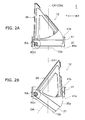
- FIGS. 2A and 2B are schematic side views that illustrate a part of the lighting device related to the first embodiment.
- FIGS. 2A and 2B illustrate the lighting main body 12 and the first frame body 41. Furthermore, in FIGS. 2A and 2B , in order to easily see the supported lighting main body 12, the first frame body 41 is illustrated in a cut state.
- the first frame body 41 rotates the lighting main body 12 around a rotation axis RA.
- the rotation axis RA is extended in a first direction perpendicular to a first central axis CA1 of the first frame body 41.
- the rotation axis RA is separated from the first central axis CA1 in a second direction perpendicular to the first central axis CA1 and the first direction.
- the first central axis CA1 is an axis that is parallel to an extension direction of the first tubular frame body 41 and passes through a center of a cross-section perpendicular to the extension direction.
- the direction of the rotation of the lighting main body 12 around the rotation axis RA will be referred to as a "first rotation direction RD1".
- the direction parallel to the first central axis CA1 is referred to as a Z axis direction.
- One direction perpendicular to the Z axis direction is referred to as an X axis direction.
- a direction perpendicular to the Z axis direction and the X axis direction is referred to as a Y axis direction.
- the first direction is the X axis direction
- the second direction is the Y axis direction. That is, in the example, the rotation axis RA is extended in the X axis direction and is separated from the first central axis CA1 in the Y axis direction.
- the first frame body 41 is able to move the lighting main body 12 to a first position illustrated in FIG. 2A and a second position illustrated in FIG. 2B , by rotating the lighting main body 12 in the first rotation direction RD1.
- an optical axis OA of illumination beam is parallel to the first central axis CA1.
- the optical axis OA of illumination beam is inclined with respect to the first central axis CA1.
- the lighting device 10 is a so-called universal type lighting device.
- the optical axis OA is an axis that passes through the center of light flux irradiated from the irradiation window 12a.
- the first frame body 41 projects a part 20p of the radiator 20 and the irradiation window 12a to the outside of the first frame body 41 from one end 41a of the first frame body 41.
- the one end 41a is an end portion that faces in the same direction as the irradiation window 12a of the lighting main body 12 located at the first position in two end portions of the first frame body 41.
- the entire irradiation window 12a is projected to the outside of the first frame body 41 from the one end 41a.
- the first frame body 41 locates the part 20p of the radiator 20 and the irradiation window 12a below the one end 41a of the first frame body 41.
- the lighting device 10 even when inclining the optical axis OA with respect to the first central axis CA1, it is possible to suppress the blocking of the illumination beam due to the attachment object such as the device itself and the ceiling plate.
- the second frame body 42 has a tubular main body portion 42m through which the first frame body 41 can be inserted.
- An inner diameter of the main body portion 42m of the second frame body 42 is greater than an outer diameter of the first frame body 41.
- the second frame body 42 supports the first frame body 41 inserted through the main body portion 42m around a second central axis CA2 of the main body portion 42m in a freely rotatable manner.
- the second central axis CA2 is an axis that is parallel to an extension direction of the main body portion 42m and passes through a center of a cross-section perpendicular to the extension direction.
- a direction of rotation of the first frame body 41 and the lighting main body 12 around the second central axis CA2 will be referred to as a "second rotation direction RD2".
- the main body portion 42m coaxially supports the first frame body 41. That is, in the example, the second central axis CA2 of the main body portion 42m is substantially the same as the first central axis CA1 of the first frame body 41.
- the second central axis CA2 may not be necessarily the same as the first central axis CA1.
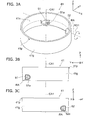
- FIGS. 3A to 3C are schematic views that illustrate the first frame body related to the first embodiment.
- FIG. 3A is a schematic perspective view
- FIG. 3B is a schematic right side view
- FIG. 3C is a schematic left side view.
- a pair of bearing portions 51 and 52 projected toward the central direction is provided on an inner surface 41n of the first frame body 41.
- the bearing portion 51 is also provided with a through hole 51a extended along the X axis direction.
- the bearing portion 52 is provided with a through hole 52a extended along the X axis direction.
- the through hole 52a is provided at a position continued to the through hole 51a in the X axis direction.
- the diameter of the through hole 52a is substantially the same as the diameter of the through hole 51a.
- the distance along the Y axis direction between the first central axis CA1 and the rotation axis RA is shorter than the radius of the inner diameter of the first frame body 41.
- the entire irradiation window 12a can be suitably projected to the outside of the first frame body 41 from the one end 41a of the first frame body 41.
- the position of the optical axis OA can be substantially the same as the position of the first central axis CA1. That is, at the first position, the lighting main body 12 can be placed in the center of the first frame body 41. Thereby, for example, the exterior of the lighting device 10 can be improved.
- the first frame body 41 is provided with a protrusion 41p.
- the protrusion 41p is projected outward from an outer surface 41g of the first frame body 41.
- the protrusion 41p is used for regulating the rotation of the first frame body 41 in the second rotation direction RD2.
- FIG. 4 is a schematic view that illustrates the second frame body related to the first embodiment.
- the second frame body 42 is provided with a flange portion 60 and a plurality of spring attachment portions 61.
- the flange portion 60 is provided in one end of the main body portion 42m.
- the flange portion 60 is projected outward from an outer surface 42g of one end of the main body portion 42m.
- the plurality of spring attachment portions 61 is placed around the second central axis CA2 at equal intervals.
- three spring attachment portions 61 are provided in the second frame body 42.
- the number of the spring attachment portions 61 may be arbitrary numbers of two or more, without being limited to three.
- An attaching spring (not illustrated) is attached to each of the plurality of spring attachment portions 61.
- the attaching spring has a flat spring shape and a torsion spring shape.
- an embedding hole is provided in the ceiling plate in advance.
- the diameter of the embedding hole is greater than the outer diameter of the main body portion 42m and is smaller than the diameter of the flange portion 60.
- the lighting device 10 inserts the second frame body 42 to the embedding hole from the interior side in a state of causing the irradiation window 12a to face the interior side, and brings an upper surface 60u of the flange portion 60 into contact with the ceiling plate.
- the ceiling plate is interposed between the flange portion 60 and the attaching spring. Thereby, the lighting device 10 is attached to the ceiling plate.
- a lower surface side of the flange portion 60 is exposed to the ceiling.
- the second frame body 42 also functions as a clock decorative rim that hides the embedding hole under a cover.
- FIG. 5 is a schematic cross-sectional view that illustrates the first frame body and the second frame body related to the first embodiment.
- the second frame body 42 is provided with a rib 62.
- the rib 62 is provided at the same side as the flange portion 60 of the main body portion 42m.
- the rib 62 is projected toward the central direction from an inner surface 42n of the second frame body 42.
- the inner diameter of the main body portion 42m of the portion provided with the rib 62 is smaller than the outer diameter of the first frame body 41.
- one annular rib 62 is provided.
- a plurality of ribs 62 may be provided around the second central axis CA2 at equal intervals, without being limited thereto.
- FIG. 6 is a schematic perspective view that illustrates a part of the first frame body and a part of the second frame body related to the first embodiment.
- a stopper member 43 is attached to each spring attachment portion 61.
- the stopper member 43 suppresses the falling-out of the first frame body 41 from the second frame body 42.
- the attaching spring is a torsion spring 63
- the stopper member 43 suppresses the falling-out of the torsion spring 63 from the spring attachment portion 61.
- the stopper member 43 is attached to the spring attachment portion 61 using the screw fastening.
- a metallic material is used in the stopper member 43.
- the stopper member 43 is formed by bending a metallic plate.
- the stopper member 43 has a spring pressing portion 43a that presses the torsion spring 63, and a pair of frame pressing portions 43b and 43c that press the first frame body 41.
- the torsion spring 63 is attached to the spring attachment portion 61 by inserting the one end thereof to a groove provided in the spring attachment portion 61.
- the stopper member 43 brings the spring pressing portion 43a into contact with a coil portion of the torsion spring 63 attached to the spring attachment portion 61, in the state of being attached to the spring attachment portion 61.
- the coil portion of the torsion spring 63 is interposed by the spring attachment portion 61 and the spring pressing portion 43a, and the torsion spring 63 is held in the spring attachment portion 61.
- the frame pressing portions 43b and 43c enter the inner surface 42n of the second frame body 42 in the state of being attached to the spring attachment portion 61, and come into contact with one end 41b (the other end) of the first frame body 41 inserted to the second frame body 42.
- the frame pressing portions 43b and 43c are elastically deformed by the contact with the one end 41b of the first frame body 41, and press the first frame body 41 against the rib 62.
- the first frame body 41 is interposed by the stopper member 43 and the rib 62, and the falling-out of the first frame body 41 from the second frame body 42 is suppressed.
- the first frame body 41 is supported by the second frame body 42 so as to be freely rotatable in the second rotation direction RD2.
- the stopper member 43 has a function of the stopper of the torsion spring 63, and a function of the stopper of the first frame body 41.
- a member for the stopper of the torsion spring 63 and a member for the stopper of the first frame body 41 may be attached to the second frame body 42, without being limited thereto.
- FIG. 7 is a schematic perspective view that illustrates a part of the first frame body and a part of the second frame body related to the first embodiment.
- FIGS. 8A and 8B are schematic top views that illustrate a part of the first frame body and a part of the second frame body related to the first embodiment.
- the second frame body 42 is provided with a rotation stop attachment portion 66 for attaching the rotation stop member 44.
- the rotation stop member 44 regulates the rotation of the first frame body 41 in the second rotation direction RD2 to a predetermined quantity or less.
- the rotation stop attachment portion 66 is provided with a pair of protrusions 67 and 68.
- the protrusion 67 has an extension portion 67a that is extended along a circumferential direction of a circle around the second central axis CA2.
- the protrusion 68 also has an extension portion 68a that is extended along a circumferential direction of a circle around the second central axis CA2.
- the extension portion 68a of the protrusion 68 is extended in an opposite direction of the extension portion 67a of the protrusion 67.
- the rotation stop attachment portion 66 is provided with a screw hole 66a.
- the screw hole 66a is placed between the protrusions 67 and 68.
- the rotation stop member 44 is attached to the rotation stop attachment portion 66 using a screw 45 (a holding member) corresponding to the screw hole 66a.
- the rotation stop member 44 has a main body 44a, an engagement portion 44b, and a frame pressing portion 44c.
- a metallic material is used as the rotation stop member 44.
- the engagement portion 44b and the frame pressing portion 44c are formed by bending the metallic plate.
- the main body portion 44a is provided with a long hole 44h. The protrusions 67 and 68 can be inserted through the long hole 44h.
- the thickness of the main body portion 44a is thinner than the heights of the protrusions 67 and 68.
- the length of the long hole 44h is longer than the length from a leading end of the extension portion 67a of the protrusion 67 to a leading end of the extension portion 68a of the protrusion 68.
- the width of the long hole 44h is wider than the widths of the protrusions 67 and 68, and is narrower than the diameter of a head portion of the screw 45.
- the rotation stop member 44 is attached to the rotation stop attachment portion 66 in the state of causing the protrusions 67 and 68 to communicate with the long hole 44h.
- the rotation stop member 44 is attached to the rotation stop attachment portion 66 so as to be freely movable in the circumferential direction of a circle around the second central axis CA2 in the range of the long hole 44h.
- the number of the protrusions provided in the rotation stop attachment portion 66 may be one or three or more, without being limited to two.
- the holding member configured to suppress the falling-out of the rotation stop member 44 from the protrusions 67 and 68 the screw 45 is illustrated.
- the holding member may be an arbitrary member such as a rivet that is able to suppress the falling-out of the rotation stop member 44, without being limited to the screw 45.
- the engagement portion 44b enters inside the movement path of the protrusion 41p provided on the outer surface 41g of the first frame body 41 in the state of attaching the rotation stop member 44 to the rotation stop attachment portion 66.
- the engagement portion 44b is engaged with the protrusion 41p and regulates the rotation of the first frame body 41 in the second rotation direction RD2 to a predetermined amount or less. Thereby, for example, it is possible to suppress the distortion of the wiring for electrically connecting a light source, an external power source or the like.
- the rotation stop member 44 is moved in the circumferential direction along the protrusions 67 and 68 when the protrusion 41p is engaged with the engagement portion 44b.
- the rotation stop member 44 is moved to a first regulation position (a position illustrated in FIG. 8A ) that regulates the rotation of the first frame body 41 in one direction of the second rotation direction RD2, and a second regulation position (a position illustrated in FIG. 8B ) that regulates the rotation of the first frame body 41 in the other direction of the second rotation direction RD2.
- the rotation quantity of the first frame body 41 in the second rotation direction RD2 can be set to 360° or more.
- the rotation quantity of the first frame body 41 in the second rotation direction RD2 can be arbitrarily set to 365°, 370° or the like.
- the lighting beam can be turned to a certain direction, while regulating the rotation to suppress the distortion of the wiring or the like.
- the frame pressing portion 44c further inwards than the inner surface 42n of the second frame body 42 in the state of being attached to the rotation stop attachment portion 66, and comes into contact with the one end 41b of the first frame body 41 inserted to the second frame body 42.
- the frame pressing portion 44c is elastically deformed by the contact with the one end 41b of the first frame body 41, and presses the first frame body 41 against the rib 62. That is, the rotation stop member 44 also functions as a stopper of the first frame body 41.
- the frame pressing portion 44c may be provided as needed and can be excluded.
- the rotation stop member 44 may not necessarily have the function of the stopper of the first frame body 41.
- the length of the frame pressing portion 44c and the lengths of the frame pressing portions 43b and 43c are longer than the protrusion quantity of the protrusion 41p from the outer surface 41g. That is, the frame pressing portion 44c and the frame pressing portions 43b and 43c retreat from the movement path of the protrusion 41p.
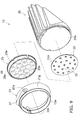
- FIG. 9 is a schematic exploded perspective view that illustrates the lighting main body related to the first embodiment.
- the lighting main body 12 has the radiator 20 and the holding frame 21, and has a substrate 22 and a lens unit 23.
- a plurality of light sources 25 is implemented on a surface 22a of the substrate 22.
- the plurality of light sources 25 is coaxially placed side by side.
- Wiring (not illustrated) is connected to the substrate 22, and electric power is supplied from the outside via the wiring. Thereby, the plurality of light sources 25 emits light depending on the electric power supply from the outside.
- a light emitting diode is used in the light source 25.
- the light source 25 may be an organic light emitting diode (OLED), an inorganic electroluminescence light emitting device, an organic electroluminescence light emitting device, other electroluminescence type light emitting device or the like.
- the radiator 20 is provided with an attachment surface 20a for attaching the substrate 22.
- the area of the attachment surface 20a is the same degree as the area of the surface 22a of the substrate 22 or is slightly greater than the area thereof.
- the substrate 22 is stuck to the attachment 20a of the radiator 20 via a heat radiation sheet or the like. Thereby, the substrate 22 is held in the radiator 20.
- heat generated according to the heat generation of each light source 25 is radiated by the radiator 20.
- the influence of heat to each light source 25 can be suppressed.
- each light source 25 or the like may be attached to the radiator 20 in a freely attachable or detachable manner.
- Each light source 25 may be exchangeable with respect to the lighting device 10.
- an optical glass, an optical plastic or the like is used in the lens unit 23.
- the lens unit 23 has optical transparency with respect to the light emitted from the light source 25.
- the lens unit 23 is transparent.
- the lens unit 23 has a cylindrical tubular portion 23a, and a lower portion 23b that blocks one end of the tubular portion 23a.
- the lens unit 23 is provided with a plurality of lenses 26.
- the plurality of lenses 26 is provided in response to the plurality of light sources 25.
- Each lens unit 26 is placed on an inner surface of the lower portion 23b.
- each lens 26 has a hemispherical shape or a conical shape.
- a concave portion 26a configured to cover each light source 25 is provided.
- the lens 26 condenses the light emitted from the light source 25, and improves irradiation efficiency of the light.
- the holding frame 21 has a cylindrical shape.
- the lens unit 23 is fitted to the inside of the holding frame 21 and is held in the holding frame 21.
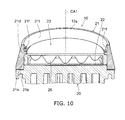
- FIG. 10 is a schematic partial cross-sectional view that illustrates the lighting main body related to the first embodiment.
- a step portion 21d configured to change the inner diameter.
- the inner diameter of a portion 21n between the step portion 21d and a rear end 21b of the inner side surface of the holding frame 21 is substantially the same as the outer diameter of the lens unit 23.
- the rear end 21b is an end portion of an opposite side of the end portion serving as the irradiation window 12a.
- the inner diameter of the holing frame 21 of the portion of the step portion 21d is narrower than the outer diameter of the lens unit 23.
- the radiator 20 is attached to the rear end 21b of the holding frame 21.
- the lens unit 23 inserted to the holding frame 21 is held in the state of being interposed between the holding frame 21 and the radiator 20.
- the length of the holding frame 21 along the optical axis OA and the length of the lens unit 23 along the optical axis OA are determined, for example, depending on the length of the lens 26 along the optical axis OA.
- the lens unit 23 is held in the holding frame 21 in the state where the positions of each light source 25 and each lens 26 are determined.
- a portion 21t between the step portion 21d of the inner surface of the holding frame 21 and the irradiation window 12a is a tapered surface in which the inner diameter thereof is continuously increased from the step portion 21d toward the irradiation window 12a.
- the portion 21t of the inner surface of the holding frame 21 is provided with a plurality of filter attachment portions 21f for attaching the filters in a freely attachable or detachable manner.
- two filter attachment portions 21f are provided.
- the two filter attachment portions 21f are provided at the positions symmetrical to each other with the optical axis OA interposed therebetween.
- the number of the filter attachment portions 21f may be three or more.
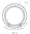
- FIG. 11 is a schematic cross-sectional view that illustrates the first frame body and the holding frame related to the first embodiment.
- a cylindrically elevated hinge portion 27 is provided on the outer surface 21g of the holding frame 21, a cylindrically elevated hinge portion 27 is provided.
- the hinge portion 27 is extended in a direction perpendicular to the optical axis OA.
- the hinge portion 27 is elevated in the Y axis direction and is extended in the X axis direction.
- cylindrical attachment holes 27a and 27b extended in the extension direction of the hinge portion 27 are provided on both ends of the hinge portion 27, cylindrical attachment holes 27a and 27b extended in the extension direction of the hinge portion 27 are provided.
- the length of the hinge portion 27 along the X axis direction is determined depending on the distance between the pair of bearing portions 51 and 52 of the first frame body 41 along the X axis direction.
- the hinge portion 27 enters between the bearing portions 51 and 52, causes the attachment hole 27a to face the through hole 51a and causes the attachment hole 27b to face the through hole 52a.
- a shaft 28a is inserted to the attachment hole 27a and the through hole 51a.
- a shaft 28b is inserted to the attachment hole 27b and the through hole 52a.
- the holding frame 21 is supported by the first frame body 41 so as to be freely rotatable in the first rotation direction RD1.
- a flat-head screw is used in the shafts 28a and 28b.
- FIGS. 12A and 12B are schematic views that illustrate the radiator related to the first embodiment.
- FIG. 12A is a schematic perspective view and
- FIG. 12B is a schematic cross-sectional view.
- the radiator 20 is provided with a plurality of flat-plate-like radiation fins 31 to 37 and a continuous portion 38. In the example, seven radiation fins 31 to 37 are provided.
- the respective radiation fins 31 to 37 are extended in a direction parallel to the optical axis OA.
- the respective radiation fins 31 to 37 are extended in a direction that is perpendicular to the rotation axis RA in the state where the lighting main body 12 is supported by the first frame body 41 (see FIGS. 2A and 2B ).
- the respective radiation fins 31 to 37 are extended in a direction that is parallel to the rotation axis RA. That is, in the example, the respective radiation fins 31 to 37 are extended in a direction parallel to the Y-Z plane and are arranged in the X axis direction.
- the radiator 20 by providing the radiator 20 with the plurality of radiation fins 31 to 37, for example, the surface area of the radiator 20 increases, and thus radiation efficiency of the radiator 20 can be increased.
- the number of the radiation fins 31 to 37 provided in the radiator 20 may be certain numbers of two or more, without being limited to seven.
- the continuous portion 38 is a portion in which each of parts of the respective radiation fins 31 to 37 is caused to continue in a part 20p exposed when the lighting main body 12 is located at the second position.
- the continuous portion 38 is configured so that the part 20p is a curved surface.
- the continuous portion 38 prevents the shapes of the respective radiation fins 31 to 37 from being exposed when locating the lighting main body 12 at the second position.
- the continuous portion 38 is a portion that covers the respective radiation fins 31 to 37 so that the respective radiation fins 31 to 37 are not exposed when locating the lighting main body 12 at the second position. Thereby, for example, the exterior of the lighting device 10 can be improved.
- the continuous portion 38 causes only a part near the outer peripheries of the respective radiation fins 31 to 37 to continue.
- the respective radiation fins 31 to 37 are extended up to the attachment surface 20a side behind the end portion 38a of the continuous portion 38.
- the thickness of the continuous portion 38 in the direction perpendicular to the optical axis OA and the rotation axis RA increases toward the attachment surface 20a side (the irradiation window 12a side) from the end portion 38a.
- the thickness of the continuous portion 38 continuously increases.
- moldability of the radiator 20 can be enhanced.
- the radiator 20 can be easily drawn from the mold.
- the respective end portions 31a to 37a of the respective radiation fins 31 to 37 are projected to the outside of the first frame body 41 and the second frame body 42 from the one end 41b of the first frame body 41 (see FIGS. 1 , 2A and 2B ).
- the one end 41b is an upper end
- the end portions 31a to 37a are placed above the one end 41b and the one end of the second frame body 42 of the same side as the one end 41b.
- each of the lengths of the respective radiation fins 31 to 37 along the optical axis OA is reduced perpendicularly to the rotation axis RA and in the direction toward the optical axis OA from the rotation axis RA. Furthermore, each of the lengths of the respective radiation fins 31 to 37 along the optical axis OA is shortened as being separated from the center in the direction (the X axis direction) along the rotation axis RA. That is, in the example, the radiation fin 34 located in the center in the X axis direction is the longest, and the radiation fin 31 and the radiation fin 37 are the shortest.
- each of the respective radiation fins 31 to 37 is located inside the outer surface 42g of the main body portion 42m of the second frame body 42 in the direction perpendicular to the second central axis CA2.
- each of the respective radiation fins 31 to 37 is located inside the outer surface 42g when being projected to the plane (the X-Y plane) perpendicular to the second central axis CA2.
- each of the respective radiation fins 31 to 37 is located inside the outer surface 42g of the main body portion 42m of the second frame body 42 in the direction perpendicular to the second central axis CA2 (see FIGS. 2A and 2B ).
- the space required for installing the lighting device 10 can be saved.
- the space required for an attic can be saved.
- a plurality of lighting device 10 may be installed side by side. At this time, if the radiator 20 is projected outside the outer surface 42g, when rotating the lighting main body 12 in the second rotation direction RD2, the radiator 20 may come into contact with the radiator 20 of the next lighting device 10. On the contrary, in the lighting device 10 related to the embodiment, since the radiator 20 is located inside the outer surface 42g, even when installing the plurality of lighting devices 10 side by side, the adjustment of the direction of the second rotation direction RD2 can be smoothly performed.
- each of the respective radiation fins 31 to 37 does not come into contact with the first frame 41 (see FIG. 2B ).
- FIG. 13 is a schematic perspective view that illustrates a filter related to the first embodiment.
- FIG. 13 illustrates a filter 80 that is attached to the lighting main body 12 in a freely attachable or detachable manner.
- the filter 80 has a disk-shaped filter main body 81, and a plurality of engagement claws 82.
- the filter 80 is a color rendering property filter that cuts a predetermined wavelength to raise color rendering property.
- the filter 80 may be other optical filters such as an ND filter and a color filter.
- the diameter of the filter main body 81 is substantially the same as the inner diameter of the portion in which each filter attachment portion 21f of the holding frame 21 is provided.
- a side surface 81s of the filter main body 81 is a tapered surface.
- the angle of the side surface 81s is substantially the same as the angle of the portion 21t of the tapered surface of the holding frame 21.
- the plurality of engagement claws 82 is provided in response to the plurality of filter attachment portions 21f of the holding frame 21.
- two engagement claws 82 are provided.
- Each engagement portion 82 is provided so as to be projected in a radial direction from the side surface 81s of the filter main body 81.
- each engagement claw 82 has a rectangular shape.
- the shape of each engagement claw 82 may be an arbitrary shape that can be attached to each filter attachment portion 21f.
- the position of each engagement claw 82 corresponds to the position of each filter attachment portion 21f.
- the respective engagement claws 82 are provided at the positions symmetrical to each other with the center of the filter main body 81 interposed therebetween.
- Each of the engagement claws 82 is provided with a hemispherical convex portion 82a.
- the convex portion 82a is provided on the surface facing the optical axis direction of the engagement claw 82.
- FIGS. 14A and 14B are schematic perspective views that illustrate a holding frame related to the first embodiment.
- the filter attachment portion 21f has an insertion-extraction portion 85 and an engagement groove 86.
- the insertion-extraction portion 85 is a portion that dents a part of the portion 21t of the tapered surface of the holding frame 21 and is substantially parallel to the optical axis OA.
- the depth (a dent quantity from the inner surface of the holding frame 21) of the insertion-extraction portion 85 corresponds to the length (a projection quantity from the side surface 81s) of the engagement claw 82 of the filter 80.
- the engagement claw 82 can be inserted to and extracted from the irradiation window 12a side in the optical axial direction.
- a lower portion 85b of the insertion-extraction portion 85 is provided with a concave portion 85c engaged with the convex portion 82a of the engagement claw 82.
- the engagement groove 86 is circumferentially extended from the lower portion 85b of the insertion-extraction portion 85.
- the height of the engagement groove 86 is slightly higher than the thickness of the engagement claw 82.
- the engagement groove 86 is provided with a concave portion 86c engaged with the convex portion 82a of the engagement claw 82.
- each engagement claw 82 When attaching the filter 80, each engagement claw 82 is caused to enter the insertion-extraction portion 85 of each filter attachment portion 21f, and the filter 80 is inserted to the holding frame 21. Each engagement claw 82 is pressed against the lower portion 85b of each insertion-extraction portion 85, and the filter 80 is rotated around the optical axis. Each engagement claw 82 is caused to enter each engagement groove 86, thereby to engage each convex portion 82a and each concave portion 86c with each other. Thereby, as illustrated in FIG.
- the falling-out of the filter 80 in the optical axial direction is regulated by the engagement between each engagement claw 82 and each engagement groove 86
- the rotation of the filter 80 around the optical axis is regulated by the engagement between each convex portion 82a and each concave portion 86c, and thus the filter 80 is held by each filter attachment portion 21f.
- each engagement claw 82 is drawn from each engagement groove 86, and each engagement claw 82 is drawn to the irradiation window 12a side from each insertion-extraction portion 85.
- the filter 80 can be easily attached to or detached from the holding frame 21 by the simple operation of merely rotating the filter 80 around the optical axis. Furthermore, the filter 80 can be suitably held in each filter attachment portion 21f, by the engagement between each engagement claw 82 and each engagement groove 86 and the engagement between each convex portion 82a and each concave portion 86c.
- the concave portion may be provided in the engagement claw 82, and the concave portion may be provided in the insertion-extraction portion 85 and the engagement groove 86.
- the shape of the concave portion may be an arbitrary shape capable of being engaged, without being limited to a hemispherical shape.
- the rotation stop member 44 is moved to the first regulation position and the second regulation position by the engagement with the protrusion 41p provided in the first frame body 41.
- the degree of freedom for changing the rotation degree of the second rotation direction RD2 can be further enhanced in the lighting device 10.
- the rotation quantity of the first frame body 41 in the second rotation direction RD2 is about 350° to 355°.
- the rotation quantity of the first frame body 41 in the second rotation direction RD2 can be set to 360° or more.
- the first frame body 41 has a longitudinal tubular shape. Therefore, for example, the deformation of the first frame body 41 can be suppressed when adjusting the direction of the illumination beam by rotating the lighting main body 12 in the second rotation direction RD2, and thus the adjustment of the direction of the second rotation direction RD2 can be smoothly performed.
- FIG. 15 is a schematic perspective view that illustrates a lighting device related to a second embodiment.
- a lighting device 110 related to the embodiment includes a lighting main body 112 that irradiates light toward an object, and a support portion 114 that supports the lighting main body 112.
- the lighting device 110 the detailed descriptions of the same functions and configurations as the first embodiment will be omitted.
- the lighting main body 112 has a radiator 120 and a holding frame 121.
- the radiator 120 a plurality of radiation fins 131 to 137 is arranged side by side.
- the holding frame 121 is provided with an irradiation window 112a for emitting the illumination beam.
- the lighting main body 112 is further provided with the substrate 22, the lens unit 23 or the like.
- the lighting main body 112 emits the light emitting light of the light source 25 as the illumination beam from the irradiation window 112a.
- the support portion 114 has a first frame body 141 and a second frame body 142.
- the first frame body 141 and the second frame body 142 have a tubular shape.
- the lighting main body 112 is also supported by the support portion 114 so as to be freely rotatable in the first rotation direction RD1 and the second rotation direction RD2, using the first frame body 141 and the second frame body 142.
- the second frame body 142 has a tubular-shape main body portion 142m capable of inserting the first frame body 141 therethrough, and a flange portion 160 projected outward from an outer surface 142g of one end of the main body portion 142m.
- the main body portion 142m is provided with a plurality of spring attachment portions 161 for attaching the attaching spring.
- the three spring attachment portions 161 are placed around the second central axis CA2 at equal intervals. In the example, for example, by interposing the ceiling plate between the flange portion 160 and the attaching spring, the lighting device 110 is attached to the ceiling.
- FIGS. 16A and 16B are schematic side views that illustrate the lighting main body and the first frame body related to the second embodiment.
- the first frame body 141 is provided with a pair of bearing portions 151.
- Each bearing portion 151 is extended from one end 141a of the first frame body 141 along a direction along the first central axis CA1.
- the respective bearing portions 151 are provided, for example, at the positions facing each other with the first central axis CA1 interposed therebetween.
- the respective bearing portions 151 are provided with a through hole 151a for inserting the shaft therethrough.
- a cylindrical attachment hole for inserting the shaft therethrough is provided in the holding frame 121.
- the lighting main body 112 is supported by the first frame body 141 so as to be freely rotatable around the rotation axis RA.
- the lighting main body 112 is also rotated in the first rotation direction RD1, and is moved to the first position illustrated in FIG. 16A or the second position illustrated in FIG. 16B .
- the optical axis OA of the illumination beam is parallel to the first central axis CA1.
- the optical axis OA of the illumination beam is inclined with respect to the first central axis CA1.
- each of the respective radiation fins 131 to 137 is located further inside the outer surface 142g of the main body portion 142m of the second frame body 142 in a direction perpendicular to the second central axis CA2, even when the lighting main body 112 is located either at the first position or at the second position. Furthermore, each of the respective radiation fins 131 to 137 does not come into contact with the first frame body 141 when the lighting main body 112 is located at the second position.
- the distance between the rotation axis RA and the first central axis CA1 along the Y axis direction is shorter than the distance between the rotation axis RA of the first frame body of the above-mentioned first embodiment and the first central axis CA1 along the Y axis direction.
- the position of the rotation axis RA in the Y axis direction may be substantially the same as the position of the first central axis CA1 in the Y axis direction. That is, the rotation axis RA may intersect with the first central axis CA1.
- the height (the length along the first central axis CA1) of the first frame body 141 is lower than the height of the first frame body 41 of the above-mentioned first embodiment.
- the first frame body 141 can also have an annular shape.
- a shape similar to the annular shape having the relatively low height is also included in a tubular shape.
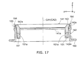
- FIG. 17 is a schematic cross-sectional view that illustrates the first frame body and the second frame body related to the second embodiment.
- a rib 153 projected outward is provided on the outer surface of the first frame body 141.
- the outer diameter of the first frame body 141 of a portion between the rib 153 and the one end 141a is smaller than the inner diameter of the second frame body 142.
- the outer diameter of the first frame body 141 of the rib portion 153 is greater than the inner diameter of the second frame body 142.
- the first frame body 141 brings the rib 153 into contact with the one end 142a of the second frame body 142 when being inserted to the second frame body 142. Thereby, the falling-out in one direction from the second frame body 142 is regulated.
- the second frame body 142 is provided with a pair of engagement claws 164.
- the respective engagement claws 164 are placed at the positions symmetrical to each other with the second central axis CA2 interposed therebetween.
- the respective engagement claws 164 are elastically deformed to allow the insertion of the rib 153, and then are engaged with the rib 153 to regulate the falling-out of the first frame body 141 in the other direction from the second frame body 142.
- the falling-out of the first frame body 141 is regulated, and the first frame body 141 is supported by the second frame body 142 so as to be freely rotatable in the second rotation direction RD2.
- the number of the engagement claw 164 may be three or more, without being limited to two.
- FIGS. 18A and 18B are schematic views that illustrate the second frame body related to the second embodiment.
- FIGS. 19A and 19B are schematic top views that illustrate a part of the first frame body and a part of the second frame body related to the second embodiment.
- the second frame body 142 is provided with a rotation stop attachment portion 166 for attaching a rotation stop member 144.
- the rotation stop attachment portion 166 has a support surface 166f dented from the one end 142a of the second frame body 142.
- the support surface 166f is provided with a protrusion 167.
- the protrusion 167 is extended along a circumferential direction of a circle around the second central axis CA2.
- the projection quantity of the protrusion 167 from the support surface 166f is smaller than the dent quantity of the support surface 166f from the one end 142a. That is, the protrusion 167 is not projected from the one end 142a in the direction along the second central axis CA2.
- the rotation stop member 144 has a main body portion 144a and an engagement portion 144b.
- the main body portion 144a is provided with a long hole 144h through which the protrusion 167 can be inserted.
- the thickness of the main body portion 144a is thinner than the height of the protrusion 167.
- the length of the long hole 144h is longer than the length of the protrusion 167 in the circumferential direction.
- the width of the long hole 44h is wider than the width of the protrusion 167.
- the rotation stop member 144 is interposed between the first frame body 141 and the rotation stop attachment portion 166. More specifically, the rotation stop member 144 is interposed between the rib 153 and the support surface 166f. Thereby, the falling-out of the rotation stop member 144 from the protrusion 167 is suppressed.
- the engagement portion 144b enters the movement path of a protrusion 141p provided in the first frame body 141 in the state of attaching the rotation stop member 144 to the rotation stop attachment portion 166.
- the protrusion 141p is projected from the one end 141b of the first frame body 141 in the direction along the first central axis CA1 (see FIGS. 16A and 16B ).
- the engagement portion 144b inwards the outer surface of the first frame body 141 in the state of attaching the rotation stop member 144 to the rotation stop attachment portion 166.
- the engagement portion 144b comes into contact with the one end 141b of the first frame body 141.
- the engagement portion 144b is engaged with the protrusion 141p, and regulates the rotation of the first frame body 141 in the second rotation direction RD2 to a predetermined quantity or less.
- the rotation stop member 144 When the protrusion 141p is engaged with the engagement portion 144b, the rotation stop member 144 is circumferentially moved along the protrusion 167. The rotation stop member 144 is moved to a first regulation position (a position illustrated in FIG. 19A ) that regulates the rotation of the first frame body 141 in one direction of the second rotation direction RD2, and a second regulation position (a position illustrated in FIG. 19B ) that regulates the rotation of the first frame body 141 in the other direction of the second rotation direction RD2.
- the rotation quantity of the first frame body 141 in the second rotation direction RD2 can also be set to 360° or more.
- the degree of freedom of the change of the degree of the rotation of the second rotation direction RD2 can be further enhanced.
- the lighting beam can be turned to an arbitrary direction, while regulating the rotation to suppress the distortion of the wiring or the like.
- the attaching work of the lighting device 110 can be easily performed.
- the lighting main body 12 is supported so as to be freely rotatable in the first rotation direction RD1 and the second rotation direction RD2.
- the support portion may support the lighting main body so as to be freely rotatable only in the second rotation direction RD2.
- the first frame body may support the lighting main body in the state of inclining the optical axis OA of the illumination beam with respect to the first central axis CA1 (the second position state).
- the radiator 20, 120 may have an attachment surface 20a for attaching a substrate 22, and the substrate 22 may have a surface 22a and include a plurality of light sources 25 provided on the surface 22a.
- the light source 25 may be a light emitting diode.
- the lighting main body 12, 112 may have a lens unit 23 that is provided with a plurality of lenses 26 each corresponding to each of the plurality of light sources 25.
- the lighting main body 12, 112 may have a plurality of filter attachment portions 21f for attaching the filter 80 in a freely attachable or detachable manner.
- the filter 80 may have a plurality of engagement claws 82 each corresponding to each of the plurality of filter attachment portions 21f, and the plurality of filter attachment portions 21f may have an insertion-extraction portion 85 that inserts or extracts the engagement claws 82 in an optical axial direction to or from the irradiation window 12a, 112a side, and an engagement groove 86 that circumferentially extends from a lower portion 85b of the insertion-extraction portion 85 and is engaged with the engagement claws 82.
Landscapes
- Engineering & Computer Science (AREA)
- General Engineering & Computer Science (AREA)
- Physics & Mathematics (AREA)
- Geometry (AREA)
- Non-Portable Lighting Devices Or Systems Thereof (AREA)
Abstract
Description
- Embodiments described herein relate generally to a lighting device.
- There has been a universal type lighting device capable of changing an irradiation direction of light. The universal type lighting device has a lighting main body provided with an irradiation window through which light is emitted, and rotates the lighting main body around an axis perpendicular to an attachment surface such as a ceiling. In such a lighting device, it is preferable to further increase a degree of freedom of the degree change.
-
-
FIG. 1 is a schematic perspective view that illustrates a lighting device related to a first embodiment; -
FIGS. 2A and 2B are schematic side views that illustrate a part of the lighting device related to the first embodiment; -
FIGS. 3A to 3C are schematic views that illustrate a first frame body related to the first embodiment; -
FIG. 4 is a schematic view that illustrates a second frame body related to the first embodiment; -
FIG. 5 is a schematic cross-sectional view that illustrates the first frame body and the second frame body related to the first embodiment; -
FIG. 6 is a schematic perspective view that illustrates a part of the first frame body and a part of the second frame body related to the first embodiment; -
FIG. 7 is a schematic perspective view that illustrates a part of the first frame body and a part of the second frame body related to the first embodiment; -
FIGS. 8A and 8B are schematic top views that illustrate a part of the first frame body and a part of the second frame body related to the first embodiment; -
FIG. 9 is a schematic exploded perspective view that illustrates a lighting main body related to the first embodiment; -
FIG. 10 is a schematic partial cross-sectional view that illustrates the lighting main body related to the first embodiment; -
FIG. 11 is a schematic cross-sectional view that illustrates the first frame body and a holding frame related to the first embodiment; -
FIGS. 12A and 12B are schematic views that illustrate a radiator related to the first embodiment; -
FIG. 13 is a schematic perspective view that illustrates a filter related to the first embodiment; -
FIGS. 14A and 14B are schematic perspective views that illustrate the holding frame related to the first embodiment; -
FIG. 15 is a schematic perspective view that illustrates a lighting device related to a second embodiment; -
FIGS. 16A and 16B are schematic side views that illustrate a lighting main body and a first frame body related to the second embodiment; -
FIG. 17 is a schematic cross-sectional view that illustrates the first frame body and a second frame body related to the second embodiment; -
FIGS. 18A and 18B are schematic views that illustrate the second frame body related to the second embodiment; and -
FIGS. 19A and 19B are schematic top views that illustrate a part of the first frame body and a part of the second frame body related to the second embodiment. - According to the exemplary embodiments, there is provided a lighting device that includes a lighting main body and a support portion. The lighting main body has an irradiation window that emits light. The support portion has a first tubular frame body through which the lighting main body can be inserted, and a second tubular frame body through which the first frame body can be inserted. The support portion supports the lighting main body inserted through the first frame body in the state of inclining an optical axis of the light with respect to a central axis of the first frame body, and supports the first frame body inserted through the second frame body so as to be freely rotatable manner around a central axis of the second frame body. The support portion has a rotation stop member that is engaged with a protrusion provided in the first frame body to regulate the rotation of the first frame body. The rotation stop member is attached to the second frame body so as to be freely movable in a circumferential direction of a circle around the central axis of the second frame body, and is moved to a first regulation position that regulates the rotation of the first frame body in one direction around the central axis of the second frame body and a second regulation position that regulates the rotation thereof in the other direction.
- Hereinafter, each embodiment will be described while referring to the drawings.
- In addition, the drawings are schematic or conceptual, a relationship between a thickness and a width of each portion, a ratio of a size between the portions or the like may not be necessarily the same as the actual ones. Furthermore, even when indicating the same portion, in some cases, each dimension and ratio may be different depending on the drawings.
- In addition, in the specification and each drawing, the same elements as described above in regard to the drawings are denoted by the same reference numerals, and the detailed descriptions thereof will be omitted.
-
FIG.1 is a schematic perspective view that illustrates a lighting device related to the first embodiment. - As illustrated in
FIG. 1 , alighting device 10 includes a lightingmain body 12 that irradiates the light toward an object, and asupport portion 14 that supports the lightingmain body 12. - The lighting
main body 12 holds a light source therein. The lightingmain body 12 has anirradiation window 12a for emitting the light (hereinafter, referred to as an illumination beam) generated from a light source. The illumination beam is emitted to the outside of the lightingmain body 12 via theirradiation window 12a. Thereby, the object is irradiated with the illumination beam. - For example, the lighting
main body 12 has aradiator 20 and aholding frame 21. For example, theradiator 20 performs the radiation of heat generated with the light emission of the light source. As theradiator 20, for example, a metallic material having high thermal conductivity such as aluminum is used. Theholding frame 21 holds theradiator 20, a lens provided inside or the like. For example, theholding frame 21 has a tubular shape. In the example, theholding frame 21 has a cylindrical shape. In the example, one end of theholding frame 21 is anirradiation window 12a. Theradiator 20 is attached to the other end of theholding frame 21. That is, theradiator 20 is provided on an opposite side of theirradiation window 12a. - The
support portion 14 is used for supporting the lightingmain body 12 and is used for attaching thelighting device 10 to an attachment object such as a ceiling plate. For example, thelighting device 10 is attached to the ceiling plate with theirradiation window 12a facing downward. For example, thelighting device 10 is embedded in an embedding hole provided in the ceiling plate. That is, thelighting device 10 is used as a so-called down-light. Hereinafter, an example of a case of using thelighting device 10 as the down-light will be described. However, for example, the attachment object of thelighting device 10 may be an inner wall plate or the like, without being limited to the ceiling plate. Furthermore, for example, thelighting device 10 may be attached to an exclusive attaching jig, and thelighting device 10 may be attached to the ceiling or the like via the attaching jig. That is, the attachment object of thelighting device 10 may be the attaching jig or the like. - The holding
portion 14 has afirst frame body 41 and asecond frame body 42. Thefirst frame body 41 and thesecond frame body 42 have a tubular shape. In the example, thefirst frame body 41 and thesecond frame body 42 have a cylindrical shape. Thesupport portion 14 supports the lightingmain body 12 so as to be freely rotatable in a state of being inserted through thefirst frame body 41. Thefirst frame body 41 supports the inserted lightingmain body 12 in a freely rotatable manner. In the example, thefirst frame body 41 supports the holdingframe 21 in a freely rotatable manner. Thefirst frame body 41 and thesecond frame body 42 may have, for example, an arbitrary shape of a tubular shape such as a square tubular shape, without being limited to the cylindrical shape. -
FIGS. 2A and 2B are schematic side views that illustrate a part of the lighting device related to the first embodiment. -
FIGS. 2A and 2B illustrate the lightingmain body 12 and thefirst frame body 41. Furthermore, inFIGS. 2A and 2B , in order to easily see the supported lightingmain body 12, thefirst frame body 41 is illustrated in a cut state. - As illustrated in
FIGS. 2A and 2B , thefirst frame body 41 rotates the lightingmain body 12 around a rotation axis RA. The rotation axis RA is extended in a first direction perpendicular to a first central axis CA1 of thefirst frame body 41. Furthermore, the rotation axis RA is separated from the first central axis CA1 in a second direction perpendicular to the first central axis CA1 and the first direction. For example, the first central axis CA1 is an axis that is parallel to an extension direction of the firsttubular frame body 41 and passes through a center of a cross-section perpendicular to the extension direction. Herein, the direction of the rotation of the lightingmain body 12 around the rotation axis RA will be referred to as a "first rotation direction RD1". - Herein, the direction parallel to the first central axis CA1 is referred to as a Z axis direction. One direction perpendicular to the Z axis direction is referred to as an X axis direction. A direction perpendicular to the Z axis direction and the X axis direction is referred to as a Y axis direction. In the example, the first direction is the X axis direction, and the second direction is the Y axis direction. That is, in the example, the rotation axis RA is extended in the X axis direction and is separated from the first central axis CA1 in the Y axis direction.
- The
first frame body 41 is able to move the lightingmain body 12 to a first position illustrated inFIG. 2A and a second position illustrated inFIG. 2B , by rotating the lightingmain body 12 in the first rotation direction RD1. At the first position, an optical axis OA of illumination beam is parallel to the first central axis CA1. Meanwhile, at the second position, the optical axis OA of illumination beam is inclined with respect to the first central axis CA1. Thereby, in thelighting device 10, an irradiated direction of the illumination beam can be changed. That is, thelighting device 10 is a so-called universal type lighting device. For example, the optical axis OA is an axis that passes through the center of light flux irradiated from theirradiation window 12a. - Furthermore, when locating the lighting
main body 12 at the second position, thefirst frame body 41 projects apart 20p of theradiator 20 and theirradiation window 12a to the outside of thefirst frame body 41 from oneend 41a of thefirst frame body 41. The oneend 41a is an end portion that faces in the same direction as theirradiation window 12a of the lightingmain body 12 located at the first position in two end portions of thefirst frame body 41. In the example, at the second position, theentire irradiation window 12a is projected to the outside of thefirst frame body 41 from the oneend 41a. For example, when the oneend 41a is a lower end facing downward with respect to the ceiling, thefirst frame body 41 locates thepart 20p of theradiator 20 and theirradiation window 12a below the oneend 41a of thefirst frame body 41. - Thereby, in the
lighting device 10, even when inclining the optical axis OA with respect to the first central axis CA1, it is possible to suppress the blocking of the illumination beam due to the attachment object such as the device itself and the ceiling plate. - The
second frame body 42 has a tubularmain body portion 42m through which thefirst frame body 41 can be inserted. An inner diameter of themain body portion 42m of thesecond frame body 42 is greater than an outer diameter of thefirst frame body 41. Thesecond frame body 42 supports thefirst frame body 41 inserted through themain body portion 42m around a second central axis CA2 of themain body portion 42m in a freely rotatable manner. Thereby, in thelighting device 10, by rotating the lightingmain body 12 around the rotation axis RA and rotating thefirst frame body 41 and the lightingmain body 12 around the second central axis CA2, the illumination beam can face in an arbitrary direction. For example, the second central axis CA2 is an axis that is parallel to an extension direction of themain body portion 42m and passes through a center of a cross-section perpendicular to the extension direction. Hereinafter, a direction of rotation of thefirst frame body 41 and the lightingmain body 12 around the second central axis CA2 will be referred to as a "second rotation direction RD2". - For example, the
main body portion 42m coaxially supports thefirst frame body 41. That is, in the example, the second central axis CA2 of themain body portion 42m is substantially the same as the first central axis CA1 of thefirst frame body 41. The second central axis CA2 may not be necessarily the same as the first central axis CA1. -
FIGS. 3A to 3C are schematic views that illustrate the first frame body related to the first embodiment. -
FIG. 3A is a schematic perspective view,FIG. 3B is a schematic right side view, andFIG. 3C is a schematic left side view. - As illustrated in
FIGS. 3A to 3C , on aninner surface 41n of thefirst frame body 41, a pair of bearingportions portion 51 is also provided with a throughhole 51a extended along the X axis direction. Similarly, the bearingportion 52 is provided with a throughhole 52a extended along the X axis direction. The throughhole 52a is provided at a position continued to the throughhole 51a in the X axis direction. The diameter of the throughhole 52a is substantially the same as the diameter of the throughhole 51a. Thereby, the rotation axis RA is set at a position separated in the Y axis direction from the first central axis CA1 by the throughholes portions - In the example, the distance along the Y axis direction between the first central axis CA1 and the rotation axis RA is shorter than the radius of the inner diameter of the
first frame body 41. Thereby, for example, at the second position, theentire irradiation window 12a can be suitably projected to the outside of thefirst frame body 41 from the oneend 41a of thefirst frame body 41. Furthermore, for example, at the first position, the position of the optical axis OA can be substantially the same as the position of the first central axis CA1. That is, at the first position, the lightingmain body 12 can be placed in the center of thefirst frame body 41. Thereby, for example, the exterior of thelighting device 10 can be improved. - Furthermore, the
first frame body 41 is provided with aprotrusion 41p. Theprotrusion 41p is projected outward from anouter surface 41g of thefirst frame body 41. Theprotrusion 41p is used for regulating the rotation of thefirst frame body 41 in the second rotation direction RD2. -
FIG. 4 is a schematic view that illustrates the second frame body related to the first embodiment. - The
second frame body 42 is provided with aflange portion 60 and a plurality ofspring attachment portions 61. Theflange portion 60 is provided in one end of themain body portion 42m. Theflange portion 60 is projected outward from anouter surface 42g of one end of themain body portion 42m. For example, the plurality ofspring attachment portions 61 is placed around the second central axis CA2 at equal intervals. In the example, threespring attachment portions 61 are provided in thesecond frame body 42. The number of thespring attachment portions 61 may be arbitrary numbers of two or more, without being limited to three. An attaching spring (not illustrated) is attached to each of the plurality ofspring attachment portions 61. For example, the attaching spring has a flat spring shape and a torsion spring shape. - When installing the
lighting device 10 on the ceiling, an embedding hole is provided in the ceiling plate in advance. At this time, the diameter of the embedding hole is greater than the outer diameter of themain body portion 42m and is smaller than the diameter of theflange portion 60. Thelighting device 10 inserts thesecond frame body 42 to the embedding hole from the interior side in a state of causing theirradiation window 12a to face the interior side, and brings anupper surface 60u of theflange portion 60 into contact with the ceiling plate. Moreover, the ceiling plate is interposed between theflange portion 60 and the attaching spring. Thereby, thelighting device 10 is attached to the ceiling plate. A lower surface side of theflange portion 60 is exposed to the ceiling. Thesecond frame body 42 also functions as a clock decorative rim that hides the embedding hole under a cover. -
FIG. 5 is a schematic cross-sectional view that illustrates the first frame body and the second frame body related to the first embodiment. - As illustrated in
FIGS. 4 and5 , thesecond frame body 42 is provided with arib 62. Therib 62 is provided at the same side as theflange portion 60 of themain body portion 42m. Therib 62 is projected toward the central direction from aninner surface 42n of thesecond frame body 42. The inner diameter of themain body portion 42m of the portion provided with therib 62 is smaller than the outer diameter of thefirst frame body 41. Thereby, thefirst frame body 41 inserted to thesecond frame body 42 comes into contact with therib 62, and the falling-out from thesecond frame body 42 is suppressed. In the example, oneannular rib 62 is provided. For example, a plurality ofribs 62 may be provided around the second central axis CA2 at equal intervals, without being limited thereto. -
FIG. 6 is a schematic perspective view that illustrates a part of the first frame body and a part of the second frame body related to the first embodiment. - As illustrated in
FIGS. 1 and6 , astopper member 43 is attached to eachspring attachment portion 61. Thestopper member 43 suppresses the falling-out of thefirst frame body 41 from thesecond frame body 42. Furthermore, for example, as illustrated inFIG. 6 , when the attaching spring is atorsion spring 63, thestopper member 43 suppresses the falling-out of thetorsion spring 63 from thespring attachment portion 61. - For example, the
stopper member 43 is attached to thespring attachment portion 61 using the screw fastening. For example, a metallic material is used in thestopper member 43. For example, thestopper member 43 is formed by bending a metallic plate. - The
stopper member 43 has aspring pressing portion 43a that presses thetorsion spring 63, and a pair offrame pressing portions first frame body 41. - The
torsion spring 63 is attached to thespring attachment portion 61 by inserting the one end thereof to a groove provided in thespring attachment portion 61. Thestopper member 43 brings thespring pressing portion 43a into contact with a coil portion of thetorsion spring 63 attached to thespring attachment portion 61, in the state of being attached to thespring attachment portion 61. Thereby, the coil portion of thetorsion spring 63 is interposed by thespring attachment portion 61 and thespring pressing portion 43a, and thetorsion spring 63 is held in thespring attachment portion 61. - The
frame pressing portions inner surface 42n of thesecond frame body 42 in the state of being attached to thespring attachment portion 61, and come into contact with oneend 41b (the other end) of thefirst frame body 41 inserted to thesecond frame body 42. For example, theframe pressing portions end 41b of thefirst frame body 41, and press thefirst frame body 41 against therib 62. Thereby, thefirst frame body 41 is interposed by thestopper member 43 and therib 62, and the falling-out of thefirst frame body 41 from thesecond frame body 42 is suppressed. Thereby, thefirst frame body 41 is supported by thesecond frame body 42 so as to be freely rotatable in the second rotation direction RD2. - In addition, in the example, the
stopper member 43 has a function of the stopper of thetorsion spring 63, and a function of the stopper of thefirst frame body 41. A member for the stopper of thetorsion spring 63 and a member for the stopper of thefirst frame body 41 may be attached to thesecond frame body 42, without being limited thereto. -
FIG. 7 is a schematic perspective view that illustrates a part of the first frame body and a part of the second frame body related to the first embodiment. -
FIGS. 8A and 8B are schematic top views that illustrate a part of the first frame body and a part of the second frame body related to the first embodiment. - As illustrated in
FIGS. 4 ,7 ,8A and 8B , thesecond frame body 42 is provided with a rotationstop attachment portion 66 for attaching therotation stop member 44. Therotation stop member 44 regulates the rotation of thefirst frame body 41 in the second rotation direction RD2 to a predetermined quantity or less. - The rotation
stop attachment portion 66 is provided with a pair ofprotrusions protrusion 67 has anextension portion 67a that is extended along a circumferential direction of a circle around the second central axis CA2. Similarly, theprotrusion 68 also has anextension portion 68a that is extended along a circumferential direction of a circle around the second central axis CA2. Theextension portion 68a of theprotrusion 68 is extended in an opposite direction of theextension portion 67a of theprotrusion 67. The rotationstop attachment portion 66 is provided with ascrew hole 66a. Thescrew hole 66a is placed between theprotrusions rotation stop member 44 is attached to the rotationstop attachment portion 66 using a screw 45 (a holding member) corresponding to thescrew hole 66a. - The
rotation stop member 44 has amain body 44a, anengagement portion 44b, and aframe pressing portion 44c. For example, as therotation stop member 44, a metallic material is used. For example, theengagement portion 44b and theframe pressing portion 44c are formed by bending the metallic plate. Themain body portion 44a is provided with along hole 44h. Theprotrusions long hole 44h. - The thickness of the
main body portion 44a is thinner than the heights of theprotrusions long hole 44h is longer than the length from a leading end of theextension portion 67a of theprotrusion 67 to a leading end of theextension portion 68a of theprotrusion 68. Furthermore, the width of thelong hole 44h is wider than the widths of theprotrusions screw 45. Therotation stop member 44 is attached to the rotationstop attachment portion 66 in the state of causing theprotrusions long hole 44h. Moreover, the falling-out of therotation stop member 44 from theprotrusions screw 45. Thereby, therotation stop member 44 is attached to the rotationstop attachment portion 66 so as to be freely movable in the circumferential direction of a circle around the second central axis CA2 in the range of thelong hole 44h. - In addition, the number of the protrusions provided in the rotation
stop attachment portion 66 may be one or three or more, without being limited to two. Furthermore, in the example, as the holding member configured to suppress the falling-out of therotation stop member 44 from theprotrusions screw 45 is illustrated. For example, the holding member may be an arbitrary member such as a rivet that is able to suppress the falling-out of therotation stop member 44, without being limited to thescrew 45. - The
engagement portion 44b enters inside the movement path of theprotrusion 41p provided on theouter surface 41g of thefirst frame body 41 in the state of attaching therotation stop member 44 to the rotationstop attachment portion 66. Theengagement portion 44b is engaged with theprotrusion 41p and regulates the rotation of thefirst frame body 41 in the second rotation direction RD2 to a predetermined amount or less. Thereby, for example, it is possible to suppress the distortion of the wiring for electrically connecting a light source, an external power source or the like. - Furthermore, the
rotation stop member 44 is moved in the circumferential direction along theprotrusions protrusion 41p is engaged with theengagement portion 44b. Therotation stop member 44 is moved to a first regulation position (a position illustrated inFIG. 8A ) that regulates the rotation of thefirst frame body 41 in one direction of the second rotation direction RD2, and a second regulation position (a position illustrated inFIG. 8B ) that regulates the rotation of thefirst frame body 41 in the other direction of the second rotation direction RD2. - Thereby, for example, the rotation quantity of the
first frame body 41 in the second rotation direction RD2 can be set to 360° or more. For example, the rotation quantity of thefirst frame body 41 in the second rotation direction RD2 can be arbitrarily set to 365°, 370° or the like. Thereby, the lighting beam can be turned to a certain direction, while regulating the rotation to suppress the distortion of the wiring or the like. For example, there is no limit of the direction when attaching thelighting device 10 to the ceiling or the like, and thus the attaching work of thelighting device 10 can be easily performed. - For example, the
frame pressing portion 44c further inwards than theinner surface 42n of thesecond frame body 42 in the state of being attached to the rotationstop attachment portion 66, and comes into contact with the oneend 41b of thefirst frame body 41 inserted to thesecond frame body 42. For example, theframe pressing portion 44c is elastically deformed by the contact with the oneend 41b of thefirst frame body 41, and presses thefirst frame body 41 against therib 62. That is, therotation stop member 44 also functions as a stopper of thefirst frame body 41. Theframe pressing portion 44c may be provided as needed and can be excluded. Therotation stop member 44 may not necessarily have the function of the stopper of thefirst frame body 41. - In addition, the length of the
frame pressing portion 44c and the lengths of theframe pressing portions protrusion 41p from theouter surface 41g. That is, theframe pressing portion 44c and theframe pressing portions protrusion 41p. -
FIG. 9 is a schematic exploded perspective view that illustrates the lighting main body related to the first embodiment. - As illustrated in
FIG. 9 , the lightingmain body 12 has theradiator 20 and the holdingframe 21, and has asubstrate 22 and alens unit 23. A plurality oflight sources 25 is implemented on asurface 22a of thesubstrate 22. For example, the plurality oflight sources 25 is coaxially placed side by side. Wiring (not illustrated) is connected to thesubstrate 22, and electric power is supplied from the outside via the wiring. Thereby, the plurality oflight sources 25 emits light depending on the electric power supply from the outside. - For example, a light emitting diode (LED) is used in the
light source 25. For example, thelight source 25 may be an organic light emitting diode (OLED), an inorganic electroluminescence light emitting device, an organic electroluminescence light emitting device, other electroluminescence type light emitting device or the like. - The
radiator 20 is provided with anattachment surface 20a for attaching thesubstrate 22. The area of theattachment surface 20a is the same degree as the area of thesurface 22a of thesubstrate 22 or is slightly greater than the area thereof. For example, thesubstrate 22 is stuck to theattachment 20a of theradiator 20 via a heat radiation sheet or the like. Thereby, thesubstrate 22 is held in theradiator 20. For example, heat generated according to the heat generation of eachlight source 25 is radiated by theradiator 20. For example, the influence of heat to eachlight source 25 can be suppressed. - In the example, although the
substrate 22 has a configuration stuck to theradiator 20, for example, thesubstrate 22, eachlight source 25 or the like may be attached to theradiator 20 in a freely attachable or detachable manner. Eachlight source 25 may be exchangeable with respect to thelighting device 10. - For example, an optical glass, an optical plastic or the like is used in the
lens unit 23. Thelens unit 23 has optical transparency with respect to the light emitted from thelight source 25. For example, thelens unit 23 is transparent. For example, thelens unit 23 has a cylindricaltubular portion 23a, and alower portion 23b that blocks one end of thetubular portion 23a. Thelens unit 23 is provided with a plurality oflenses 26. The plurality oflenses 26 is provided in response to the plurality oflight sources 25. Eachlens unit 26 is placed on an inner surface of thelower portion 23b. For example, eachlens 26 has a hemispherical shape or a conical shape. In a top portion of eachlens 26, aconcave portion 26a configured to cover eachlight source 25 is provided. For example, thelens 26 condenses the light emitted from thelight source 25, and improves irradiation efficiency of the light. As mentioned above, the holdingframe 21 has a cylindrical shape. Thelens unit 23 is fitted to the inside of the holdingframe 21 and is held in the holdingframe 21. -
FIG. 10 is a schematic partial cross-sectional view that illustrates the lighting main body related to the first embodiment. - As illustrated in
FIG. 10 , on the inner surface side of the holdingframe 21, astep portion 21d configured to change the inner diameter is provided. The inner diameter of aportion 21n between thestep portion 21d and arear end 21b of the inner side surface of the holdingframe 21 is substantially the same as the outer diameter of thelens unit 23. Therear end 21b is an end portion of an opposite side of the end portion serving as theirradiation window 12a. Meanwhile, the inner diameter of the holingframe 21 of the portion of thestep portion 21d is narrower than the outer diameter of thelens unit 23. Thereby, thelens unit 23 inserted to the holdingframe 21 comes into contact with thestep portion 21d, and the falling-out from the holdingframe 21 is suppressed. - The
radiator 20 is attached to therear end 21b of the holdingframe 21. Thelens unit 23 inserted to the holdingframe 21 is held in the state of being interposed between the holdingframe 21 and theradiator 20. The length of the holdingframe 21 along the optical axis OA and the length of thelens unit 23 along the optical axis OA are determined, for example, depending on the length of thelens 26 along the optical axis OA. Thelens unit 23 is held in the holdingframe 21 in the state where the positions of eachlight source 25 and eachlens 26 are determined. - A
portion 21t between thestep portion 21d of the inner surface of the holdingframe 21 and theirradiation window 12a is a tapered surface in which the inner diameter thereof is continuously increased from thestep portion 21d toward theirradiation window 12a. Theportion 21t of the inner surface of the holdingframe 21 is provided with a plurality offilter attachment portions 21f for attaching the filters in a freely attachable or detachable manner. In the example, twofilter attachment portions 21f are provided. The twofilter attachment portions 21f are provided at the positions symmetrical to each other with the optical axis OA interposed therebetween. The number of thefilter attachment portions 21f may be three or more. -
FIG. 11 is a schematic cross-sectional view that illustrates the first frame body and the holding frame related to the first embodiment. - As illustrated in
FIGS. 9 and11 , on theouter surface 21g of the holdingframe 21, a cylindricallyelevated hinge portion 27 is provided. Thehinge portion 27 is extended in a direction perpendicular to the optical axis OA. For example, thehinge portion 27 is elevated in the Y axis direction and is extended in the X axis direction. On both ends of thehinge portion 27, cylindrical attachment holes 27a and 27b extended in the extension direction of thehinge portion 27 are provided. The length of thehinge portion 27 along the X axis direction is determined depending on the distance between the pair of bearingportions first frame body 41 along the X axis direction. Thehinge portion 27 enters between the bearingportions attachment hole 27a to face the throughhole 51a and causes theattachment hole 27b to face the throughhole 52a. - A
shaft 28a is inserted to theattachment hole 27a and the throughhole 51a. Ashaft 28b is inserted to theattachment hole 27b and the throughhole 52a. Thereby, the holdingframe 21 is supported by thefirst frame body 41 so as to be freely rotatable in the first rotation direction RD1. For example, a flat-head screw is used in theshafts -
FIGS. 12A and 12B are schematic views that illustrate the radiator related to the first embodiment.FIG. 12A is a schematic perspective view andFIG. 12B is a schematic cross-sectional view. - As illustrated in
FIGS. 12A and 12B , theradiator 20 is provided with a plurality of flat-plate-like radiation fins 31 to 37 and acontinuous portion 38. In the example, sevenradiation fins 31 to 37 are provided. - The
respective radiation fins 31 to 37 are extended in a direction parallel to the optical axis OA. Therespective radiation fins 31 to 37 are extended in a direction that is perpendicular to the rotation axis RA in the state where the lightingmain body 12 is supported by the first frame body 41 (seeFIGS. 2A and 2B ). Moreover, therespective radiation fins 31 to 37 are extended in a direction that is parallel to the rotation axis RA. That is, in the example, therespective radiation fins 31 to 37 are extended in a direction parallel to the Y-Z plane and are arranged in the X axis direction. In this manner, by providing theradiator 20 with the plurality ofradiation fins 31 to 37, for example, the surface area of theradiator 20 increases, and thus radiation efficiency of theradiator 20 can be increased. In addition, the number of theradiation fins 31 to 37 provided in theradiator 20 may be certain numbers of two or more, without being limited to seven. - The
continuous portion 38 is a portion in which each of parts of therespective radiation fins 31 to 37 is caused to continue in apart 20p exposed when the lightingmain body 12 is located at the second position. For example, thecontinuous portion 38 is configured so that thepart 20p is a curved surface. Thereby, thecontinuous portion 38 prevents the shapes of therespective radiation fins 31 to 37 from being exposed when locating the lightingmain body 12 at the second position. In other words, thecontinuous portion 38 is a portion that covers therespective radiation fins 31 to 37 so that therespective radiation fins 31 to 37 are not exposed when locating the lightingmain body 12 at the second position. Thereby, for example, the exterior of thelighting device 10 can be improved. - As illustrated in
FIG. 12B , thecontinuous portion 38 causes only a part near the outer peripheries of therespective radiation fins 31 to 37 to continue. Therespective radiation fins 31 to 37 are extended up to theattachment surface 20a side behind theend portion 38a of thecontinuous portion 38. The thickness of thecontinuous portion 38 in the direction perpendicular to the optical axis OA and the rotation axis RA increases toward theattachment surface 20a side (theirradiation window 12a side) from theend portion 38a. For example, the thickness of thecontinuous portion 38 continuously increases. Thereby, for example, moldability of theradiator 20 can be enhanced. For example, when molding theradiator 20, theradiator 20 can be easily drawn from the mold. Furthermore, for example, it is possible to suppress the stagnation of heat behind thecontinuous portion 38. - When the lighting
main body 12 located either at the first position or at the second position, therespective end portions 31a to 37a of therespective radiation fins 31 to 37 are projected to the outside of thefirst frame body 41 and thesecond frame body 42 from the oneend 41b of the first frame body 41 (seeFIGS. 1 ,2A and 2B ). For example, when the oneend 41b is an upper end, theend portions 31a to 37a are placed above the oneend 41b and the one end of thesecond frame body 42 of the same side as the oneend 41b. - Each of the lengths of the
respective radiation fins 31 to 37 along the optical axis OA is reduced perpendicularly to the rotation axis RA and in the direction toward the optical axis OA from the rotation axis RA. Furthermore, each of the lengths of therespective radiation fins 31 to 37 along the optical axis OA is shortened as being separated from the center in the direction (the X axis direction) along the rotation axis RA. That is, in the example, theradiation fin 34 located in the center in the X axis direction is the longest, and theradiation fin 31 and theradiation fin 37 are the shortest. - Thereby, even when the lighting
main body 12 is located at the first position or the second position, each of therespective radiation fins 31 to 37 is located inside theouter surface 42g of themain body portion 42m of thesecond frame body 42 in the direction perpendicular to the second central axis CA2. In other words, each of therespective radiation fins 31 to 37 is located inside theouter surface 42g when being projected to the plane (the X-Y plane) perpendicular to the second central axis CA2. In the example, each of therespective radiation fins 31 to 37 is located inside theouter surface 42g of themain body portion 42m of thesecond frame body 42 in the direction perpendicular to the second central axis CA2 (seeFIGS. 2A and 2B ). - Thereby, for example, the space required for installing the
lighting device 10 can be saved. For example, the space required for an attic can be saved. Furthermore, in some cases, a plurality oflighting device 10 may be installed side by side. At this time, if theradiator 20 is projected outside theouter surface 42g, when rotating the lightingmain body 12 in the second rotation direction RD2, theradiator 20 may come into contact with theradiator 20 of thenext lighting device 10. On the contrary, in thelighting device 10 related to the embodiment, since theradiator 20 is located inside theouter surface 42g, even when installing the plurality oflighting devices 10 side by side, the adjustment of the direction of the second rotation direction RD2 can be smoothly performed. - Furthermore, in the
lighting device 10 related to the embodiment, as mentioned above, by adjusting the length along the optical axis OA, when the lightingmain body 12 is located at the second position, each of therespective radiation fins 31 to 37 does not come into contact with the first frame 41 (seeFIG. 2B ). - Thereby, when the lighting
main body 12 is located at the second position, an interval is generated between the lightingmain body 12 and thefirst frame 41. For example, an air passage passing from the interior side to the attic is generated, and thus it is possible to further enhance radiation efficiency when the lightingmain body 12 is located at the second position. -
FIG. 13 is a schematic perspective view that illustrates a filter related to the first embodiment. -
FIG. 13 illustrates afilter 80 that is attached to the lightingmain body 12 in a freely attachable or detachable manner. - As illustrated in
FIG. 13 , thefilter 80 has a disk-shaped filtermain body 81, and a plurality ofengagement claws 82. For example, thefilter 80 is a color rendering property filter that cuts a predetermined wavelength to raise color rendering property. For example, thefilter 80 may be other optical filters such as an ND filter and a color filter. - For example, the diameter of the filter
main body 81 is substantially the same as the inner diameter of the portion in which eachfilter attachment portion 21f of the holdingframe 21 is provided. For example, aside surface 81s of the filtermain body 81 is a tapered surface. For example, the angle of theside surface 81s is substantially the same as the angle of theportion 21t of the tapered surface of the holdingframe 21. - The plurality of
engagement claws 82 is provided in response to the plurality offilter attachment portions 21f of the holdingframe 21. Thus, in the example, twoengagement claws 82 are provided. Eachengagement portion 82 is provided so as to be projected in a radial direction from theside surface 81s of the filtermain body 81. In the example, eachengagement claw 82 has a rectangular shape. The shape of eachengagement claw 82 may be an arbitrary shape that can be attached to eachfilter attachment portion 21f. The position of eachengagement claw 82 corresponds to the position of eachfilter attachment portion 21f. In the example, therespective engagement claws 82 are provided at the positions symmetrical to each other with the center of the filtermain body 81 interposed therebetween. Each of theengagement claws 82 is provided with a hemisphericalconvex portion 82a. Theconvex portion 82a is provided on the surface facing the optical axis direction of theengagement claw 82. -
FIGS. 14A and 14B are schematic perspective views that illustrate a holding frame related to the first embodiment. - As illustrated in
FIGS. 14A and 14B , thefilter attachment portion 21f has an insertion-extraction portion 85 and anengagement groove 86. - The insertion-
extraction portion 85 is a portion that dents a part of theportion 21t of the tapered surface of the holdingframe 21 and is substantially parallel to the optical axis OA. The depth (a dent quantity from the inner surface of the holding frame 21) of the insertion-extraction portion 85 corresponds to the length (a projection quantity from theside surface 81s) of theengagement claw 82 of thefilter 80. Thereby, in the insertion-extraction portion 85, theengagement claw 82 can be inserted to and extracted from theirradiation window 12a side in the optical axial direction. Alower portion 85b of the insertion-extraction portion 85 is provided with aconcave portion 85c engaged with theconvex portion 82a of theengagement claw 82. - The
engagement groove 86 is circumferentially extended from thelower portion 85b of the insertion-extraction portion 85. The height of theengagement groove 86 is slightly higher than the thickness of theengagement claw 82. Theengagement groove 86 is provided with aconcave portion 86c engaged with theconvex portion 82a of theengagement claw 82. - When attaching the
filter 80, eachengagement claw 82 is caused to enter the insertion-extraction portion 85 of eachfilter attachment portion 21f, and thefilter 80 is inserted to the holdingframe 21. Eachengagement claw 82 is pressed against thelower portion 85b of each insertion-extraction portion 85, and thefilter 80 is rotated around the optical axis. Eachengagement claw 82 is caused to enter eachengagement groove 86, thereby to engage eachconvex portion 82a and eachconcave portion 86c with each other. Thereby, as illustrated inFIG. 14B , the falling-out of thefilter 80 in the optical axial direction is regulated by the engagement between eachengagement claw 82 and eachengagement groove 86, the rotation of thefilter 80 around the optical axis is regulated by the engagement between eachconvex portion 82a and eachconcave portion 86c, and thus thefilter 80 is held by eachfilter attachment portion 21f. - When detaching the
filter 80, thefilter 80 is rotated in an opposite direction of the direction at the time of the attachment, eachengagement claw 82 is drawn from eachengagement groove 86, and eachengagement claw 82 is drawn to theirradiation window 12a side from each insertion-extraction portion 85. - In this manner, in the
lighting device 10, thefilter 80 can be easily attached to or detached from the holdingframe 21 by the simple operation of merely rotating thefilter 80 around the optical axis. Furthermore, thefilter 80 can be suitably held in eachfilter attachment portion 21f, by the engagement between eachengagement claw 82 and eachengagement groove 86 and the engagement between eachconvex portion 82a and eachconcave portion 86c. In addition, on the contrary, the concave portion may be provided in theengagement claw 82, and the concave portion may be provided in the insertion-extraction portion 85 and theengagement groove 86. Furthermore, the shape of the concave portion may be an arbitrary shape capable of being engaged, without being limited to a hemispherical shape. - In the
lighting device 10 related to the embodiment, therotation stop member 44 is moved to the first regulation position and the second regulation position by the engagement with theprotrusion 41p provided in thefirst frame body 41. Thereby, the degree of freedom for changing the rotation degree of the second rotation direction RD2 can be further enhanced in thelighting device 10. For example, in a configuration in which therotation stop member 44 is fixed to thesecond frame body 42 and is not circumferentially moved, the rotation quantity of thefirst frame body 41 in the second rotation direction RD2 is about 350° to 355°. On the contrary, in thelighting device 10 related to the embodiment, the rotation quantity of thefirst frame body 41 in the second rotation direction RD2 can be set to 360° or more. - Furthermore, in the
lighting device 10, thefirst frame body 41 has a longitudinal tubular shape. Thereby, for example, the deformation of thefirst frame body 41 can be suppressed when adjusting the direction of the illumination beam by rotating the lightingmain body 12 in the second rotation direction RD2, and thus the adjustment of the direction of the second rotation direction RD2 can be smoothly performed. -
FIG. 15 is a schematic perspective view that illustrates a lighting device related to a second embodiment. - As illustrated in
FIG. 15 , as in thelighting device 10 of the above-mentioned first embodiment, alighting device 110 related to the embodiment includes a lightingmain body 112 that irradiates light toward an object, and asupport portion 114 that supports the lightingmain body 112. In thelighting device 110, the detailed descriptions of the same functions and configurations as the first embodiment will be omitted. - The lighting
main body 112 has aradiator 120 and a holdingframe 121. In theradiator 120, a plurality ofradiation fins 131 to 137 is arranged side by side. The holdingframe 121 is provided with anirradiation window 112a for emitting the illumination beam. As mentioned in the first embodiment, the lightingmain body 112 is further provided with thesubstrate 22, thelens unit 23 or the like. The lightingmain body 112 emits the light emitting light of thelight source 25 as the illumination beam from theirradiation window 112a. - The
support portion 114 has afirst frame body 141 and asecond frame body 142. For example, thefirst frame body 141 and thesecond frame body 142 have a tubular shape. In the example, the lightingmain body 112 is also supported by thesupport portion 114 so as to be freely rotatable in the first rotation direction RD1 and the second rotation direction RD2, using thefirst frame body 141 and thesecond frame body 142. - The
second frame body 142 has a tubular-shapemain body portion 142m capable of inserting thefirst frame body 141 therethrough, and aflange portion 160 projected outward from anouter surface 142g of one end of themain body portion 142m. Themain body portion 142m is provided with a plurality ofspring attachment portions 161 for attaching the attaching spring. For example, the threespring attachment portions 161 are placed around the second central axis CA2 at equal intervals. In the example, for example, by interposing the ceiling plate between theflange portion 160 and the attaching spring, thelighting device 110 is attached to the ceiling. -
FIGS. 16A and 16B are schematic side views that illustrate the lighting main body and the first frame body related to the second embodiment. - As illustrated in
FIGS. 16A and 16B , thefirst frame body 141 is provided with a pair of bearingportions 151. Each bearingportion 151 is extended from oneend 141a of thefirst frame body 141 along a direction along the first central axis CA1. Therespective bearing portions 151 are provided, for example, at the positions facing each other with the first central axis CA1 interposed therebetween. Therespective bearing portions 151 are provided with a throughhole 151a for inserting the shaft therethrough. - For example, in the holding
frame 121, at a position facing each of the throughholes 151a of each bearingportion 151 in the state of being inserted to thefirst frame body 141, a cylindrical attachment hole for inserting the shaft therethrough is provided. Thereby, by inserting the shaft to each of the respective throughholes 151a and the respective attachment holes, the lightingmain body 112 is supported by thefirst frame body 141 so as to be freely rotatable around the rotation axis RA. Thereby, in the example, the lightingmain body 112 is also rotated in the first rotation direction RD1, and is moved to the first position illustrated inFIG. 16A or the second position illustrated inFIG. 16B . At the first position, the optical axis OA of the illumination beam is parallel to the first central axis CA1. At the second position, the optical axis OA of the illumination beam is inclined with respect to the first central axis CA1. - In the example, each of the
respective radiation fins 131 to 137 is located further inside theouter surface 142g of themain body portion 142m of thesecond frame body 142 in a direction perpendicular to the second central axis CA2, even when the lightingmain body 112 is located either at the first position or at the second position. Furthermore, each of therespective radiation fins 131 to 137 does not come into contact with thefirst frame body 141 when the lightingmain body 112 is located at the second position. - In the
first frame body 141, the distance between the rotation axis RA and the first central axis CA1 along the Y axis direction is shorter than the distance between the rotation axis RA of the first frame body of the above-mentioned first embodiment and the first central axis CA1 along the Y axis direction. The position of the rotation axis RA in the Y axis direction may be substantially the same as the position of the first central axis CA1 in the Y axis direction. That is, the rotation axis RA may intersect with the first central axis CA1. - The height (the length along the first central axis CA1) of the
first frame body 141 is lower than the height of thefirst frame body 41 of the above-mentioned first embodiment. For example, thefirst frame body 141 can also have an annular shape. In the specification, a shape similar to the annular shape having the relatively low height is also included in a tubular shape. -
FIG. 17 is a schematic cross-sectional view that illustrates the first frame body and the second frame body related to the second embodiment. - As illustrated in
FIGS. 16A, 16B and17 , on the outer surface of thefirst frame body 141, arib 153 projected outward is provided. The outer diameter of thefirst frame body 141 of a portion between therib 153 and the oneend 141a is smaller than the inner diameter of thesecond frame body 142. Meanwhile, the outer diameter of thefirst frame body 141 of therib portion 153 is greater than the inner diameter of thesecond frame body 142. Thefirst frame body 141 brings therib 153 into contact with the oneend 142a of thesecond frame body 142 when being inserted to thesecond frame body 142. Thereby, the falling-out in one direction from thesecond frame body 142 is regulated. - As illustrated in
FIGS. 15 and17 , thesecond frame body 142 is provided with a pair ofengagement claws 164. For example, therespective engagement claws 164 are placed at the positions symmetrical to each other with the second central axis CA2 interposed therebetween. Therespective engagement claws 164 are elastically deformed to allow the insertion of therib 153, and then are engaged with therib 153 to regulate the falling-out of thefirst frame body 141 in the other direction from thesecond frame body 142. Thereby, the falling-out of thefirst frame body 141 is regulated, and thefirst frame body 141 is supported by thesecond frame body 142 so as to be freely rotatable in the second rotation direction RD2. In addition, the number of theengagement claw 164 may be three or more, without being limited to two. -
FIGS. 18A and 18B are schematic views that illustrate the second frame body related to the second embodiment. -
FIGS. 19A and 19B are schematic top views that illustrate a part of the first frame body and a part of the second frame body related to the second embodiment. - As illustrated in
FIG. 18A , thesecond frame body 142 is provided with a rotationstop attachment portion 166 for attaching arotation stop member 144. The rotationstop attachment portion 166 has asupport surface 166f dented from the oneend 142a of thesecond frame body 142. Thesupport surface 166f is provided with aprotrusion 167. Theprotrusion 167 is extended along a circumferential direction of a circle around the second central axis CA2. The projection quantity of theprotrusion 167 from thesupport surface 166f is smaller than the dent quantity of thesupport surface 166f from the oneend 142a. That is, theprotrusion 167 is not projected from the oneend 142a in the direction along the second central axis CA2. - The
rotation stop member 144 has amain body portion 144a and anengagement portion 144b. Themain body portion 144a is provided with along hole 144h through which theprotrusion 167 can be inserted. The thickness of themain body portion 144a is thinner than the height of theprotrusion 167. The length of thelong hole 144h is longer than the length of theprotrusion 167 in the circumferential direction. Furthermore, the width of thelong hole 44h is wider than the width of theprotrusion 167. Thereby, therotation stop member 144 is attached to the rotationstop attachment portion 166 so as to be freely movable in the circumferential direction of the circle around the second central axis CA2 in the range of thelong hole 144h. - As illustrated in
FIG. 18B , therotation stop member 144 is interposed between thefirst frame body 141 and the rotationstop attachment portion 166. More specifically, therotation stop member 144 is interposed between therib 153 and thesupport surface 166f. Thereby, the falling-out of therotation stop member 144 from theprotrusion 167 is suppressed. - The
engagement portion 144b enters the movement path of aprotrusion 141p provided in thefirst frame body 141 in the state of attaching therotation stop member 144 to the rotationstop attachment portion 166. In the example, theprotrusion 141p is projected from the oneend 141b of thefirst frame body 141 in the direction along the first central axis CA1 (seeFIGS. 16A and 16B ). Theengagement portion 144b inwards the outer surface of thefirst frame body 141 in the state of attaching therotation stop member 144 to the rotationstop attachment portion 166. For example, theengagement portion 144b comes into contact with the oneend 141b of thefirst frame body 141. Thereby, theengagement portion 144b is engaged with theprotrusion 141p, and regulates the rotation of thefirst frame body 141 in the second rotation direction RD2 to a predetermined quantity or less. - When the
protrusion 141p is engaged with theengagement portion 144b, therotation stop member 144 is circumferentially moved along theprotrusion 167. Therotation stop member 144 is moved to a first regulation position (a position illustrated inFIG. 19A ) that regulates the rotation of thefirst frame body 141 in one direction of the second rotation direction RD2, and a second regulation position (a position illustrated inFIG. 19B ) that regulates the rotation of thefirst frame body 141 in the other direction of the second rotation direction RD2. - Thereby, in the
lighting device 110 related to the embodiment, for example, the rotation quantity of thefirst frame body 141 in the second rotation direction RD2 can also be set to 360° or more. The degree of freedom of the change of the degree of the rotation of the second rotation direction RD2 can be further enhanced. The lighting beam can be turned to an arbitrary direction, while regulating the rotation to suppress the distortion of the wiring or the like. The attaching work of thelighting device 110 can be easily performed. - In the
support portions main body 12 is supported so as to be freely rotatable in the first rotation direction RD1 and the second rotation direction RD2. The support portion may support the lighting main body so as to be freely rotatable only in the second rotation direction RD2. In the case, for example, the first frame body may support the lighting main body in the state of inclining the optical axis OA of the illumination beam with respect to the first central axis CA1 (the second position state). - Although some embodiments have been described, such embodiments are presented as an example but are not intended to limit the scope of the embodiments. The new embodiments can be performed by various other embodiments, and various omissions, substitutions and changes can be made within the scope that does not apart from the gist thereof. The embodiments and the modifications thereof are included in the scope and the gist of the embodiment, and are included in the claims and the equivalents thereof.
- In the
lighting device radiator attachment surface 20a for attaching asubstrate 22, and thesubstrate 22 may have asurface 22a and include a plurality oflight sources 25 provided on thesurface 22a. - In the
lighting device light source 25 may be a light emitting diode. - In the
lighting device main body lens unit 23 that is provided with a plurality oflenses 26 each corresponding to each of the plurality oflight sources 25. - In the
lighting device main body filter attachment portions 21f for attaching thefilter 80 in a freely attachable or detachable manner. - In the
lighting device filter 80 may have a plurality ofengagement claws 82 each corresponding to each of the plurality offilter attachment portions 21f, and the plurality offilter attachment portions 21f may have an insertion-extraction portion 85 that inserts or extracts theengagement claws 82 in an optical axial direction to or from theirradiation window engagement groove 86 that circumferentially extends from alower portion 85b of the insertion-extraction portion 85 and is engaged with theengagement claws 82.
Claims (15)
- A lighting device (10, 110) comprising:a lighting main body (12, 112) having an irradiation window (12a, 112a) that emits light; anda support portion (14, 114) that has a first tubular frame body (41, 141) through which the lighting main body (12, 112) can be inserted, and a second tubular frame body (42, 142) through which the first frame body (41, 141) can be inserted, the support portion supporting the lighting main body (12, 112) inserted through the first frame body (41, 141) in a state of inclining an optical axis of the light with respect to a central axis of the first frame body (41, 141), and the support portion supporting the first frame body (41, 141) inserted through the second frame body (42, 142) so as to be freely rotatable around a central axis of the second frame body (42, 142),wherein the support portion (14, 114) has a rotation stop member (44, 144) that is engaged with a protrusion (41p, 141p) provided in the first frame body (41, 141) to regulate the rotation of the first frame body (41, 141), andthe rotation stop member (44, 144) is attached to the second frame body (42, 142) so as to be freely movable in a circumferential direction of a circle around the central axis of the second frame body (42, 142), and is moved to a first regulation position that regulates the rotation of the first frame body (41, 141) in one direction around the central axis of the second frame body (42, 142), and a second regulation position that regulates the rotation thereof in the other direction.
- The device (10, 110) according to claim 1,
wherein the second frame body (42, 142) has a rotation stop attachment portion (66, 166) for attaching the rotation stop member (44, 144),
the rotation stop attachment portion (66, 166) has a protrusion (67, 68, 167) that extends along a circumferential direction of a circle around the central axis of the second frame body (42, 142), and
the rotation stop member (44, 144) has a long hole (44h, 144h) through which the protrusion (67, 68, 167) can be inserted, and is moved to the first regulation position and the second regulation position in the range of the long hole (44h, 144h). - The device (10) according to claim 2,
wherein a holding member (45) adapted to suppress falling-out of the rotation stop member (44) from the protrusion (67, 68) is attached to the rotation stop attachment portion (66). - The device (110) according to claim 2,
wherein the rotation stop member (144) is interposed between the first frame body (141) and the rotation stop attachment portion (166), and the falling-out from the protrusion (167) is suppressed. - The device (10, 110) according to any one of claims 1 to 4,
wherein a rotation quantity of the rotation of the first frame body (41, 141) around the central axis of the second frame body (42, 142) is 360° or more. - The device according to any one of claims 1 to 5, wherein the second frame body (42, 142) coaxially supports the first frame body (41, 141).
- The device (10, 110) according to any one of claims 1 to 5,
wherein the first frame body (41, 141) supports the lighting main body (12, 112) so as to be freely rotatable around a rotation axis extending in a first direction perpendicular to the central axis of the first frame body (41, 141), and is able to move the lighting main body (12, 112) to a first position in which an optical axis of the light is parallel to the central axis, and a second position in which the optical axis is inclined with respect to the central axis of the first frame body. - The device (10) according to claim 7,
wherein the rotation axis is separated from the central axis in the second direction that is perpendicular to the central axis of the first frame body (41) and the first direction, respectively, and
the first frame body (41) projects the irradiation window from one end of the first frame body (41) to the outside of the first frame body (41) at the second position. - The device (10) according to claim 8,
wherein the lighting main body (12, 112) has a radiator (20, 120) provided on an opposite side of the irradiation window (12a, 112a), and
the first frame body (41) projects a part (20p) of the radiator (20) from the one end (41a) of the first frame body (41) to the outside of the first frame body (41) at the second position. - The device (10, 110) according to claim 9,
wherein the radiator (20, 120) has a plurality of radiation fins (31 to 37, 131 to 137) that extends in a direction parallel to the optical axis, extends in a direction perpendicular to the rotation axis, and is arranged in a direction parallel to the rotation axis. - The device (10) according to claim 10,
wherein the radiator (20) has a continuous portion (38) by which a part of each of the plurality of radiation fins (31 to 37) continues in the part (20p) of the radiator (20). - The device (10, 110) according to claim 10 or 11,
wherein an end portion of each of the plurality of radiation fins (31 to 37, 131 to 137) is projected from the other end of the first frame body (41, 141) to the outside of the first frame body (41, 141) and the second frame body (42, 142),
a length of each of the plurality of radiation fins (31 to 37, 131 to 137) along the optical axis is reduced in a direction perpendicular to the rotation axis and toward the optical axis from the rotation axis, and
each of the plurality of radiation fins (31 to 37, 131 to 137) is located inside an outer surface of the second frame body (42, 142) in a direction perpendicular to the central axis of the second frame body (42, 142) when the lighting main body (12, 112) is located either at the first position or at the second position. - The device (10, 110) according to claim 12,
wherein each of the plurality of radiation fins (31 to 37, 131 to 137) does not come into contact with the first frame body (41, 141) when the lighting main body (12, 112) is located at the second position. - The device (110) according to claim 7,
wherein the rotation axis intersects with the central axis of the first frame body (141). - The device (10, 110) according to any one of claims 1 to 14,
wherein the second frame body (42, 142) has a tubular main body portion (42m, 142m), a flange portion (60, 160) projected outward from an outer surface (42g, 142g) of the main body portion (42m, 142m), and a plurality of spring attachment portions (61, 161) for attaching an attaching spring.
Applications Claiming Priority (1)
| Application Number | Priority Date | Filing Date | Title |
|---|---|---|---|
| JP2012288199A JP2014130758A (en) | 2012-12-28 | 2012-12-28 | lighting equipment |
Publications (1)
| Publication Number | Publication Date |
|---|---|
| EP2749815A1 true EP2749815A1 (en) | 2014-07-02 |
Family
ID=47998173
Family Applications (1)
| Application Number | Title | Priority Date | Filing Date |
|---|---|---|---|
| EP13159550.6A Withdrawn EP2749815A1 (en) | 2012-12-28 | 2013-03-15 | Lighting device |
Country Status (4)
| Country | Link |
|---|---|
| US (1) | US20140185302A1 (en) |
| EP (1) | EP2749815A1 (en) |
| JP (1) | JP2014130758A (en) |
| CN (1) | CN203395860U (en) |
Cited By (2)
| Publication number | Priority date | Publication date | Assignee | Title |
|---|---|---|---|---|
| CN107726132A (en) * | 2017-10-09 | 2018-02-23 | 广东艾罗照明科技股份有限公司 | A kind of shot-light |
| AT15681U1 (en) * | 2016-03-22 | 2018-04-15 | Zumtobel Lighting Gmbh | Recessed luminaire with swiveling light source |
Families Citing this family (10)
| Publication number | Priority date | Publication date | Assignee | Title |
|---|---|---|---|---|
| JP6089369B2 (en) * | 2013-05-29 | 2017-03-08 | パナソニックIpマネジメント株式会社 | Downlight |
| JP6084183B2 (en) * | 2014-07-16 | 2017-02-22 | アルモテクノス株式会社 | LIGHTING DEVICE AND LIGHTING SYSTEM HAVING THE SAME |
| DE202014105017U1 (en) * | 2014-10-21 | 2016-01-25 | Zumtobel Lighting Gmbh | downlight |
| JP6438906B2 (en) * | 2016-04-11 | 2018-12-19 | ミネベアミツミ株式会社 | Angle adjusting device and lighting device |
| DE102018103575A1 (en) * | 2018-02-16 | 2019-08-22 | Trilux Gmbh & Co. Kg | Set for the realization of a recessed spotlight |
| JP7151321B2 (en) * | 2018-09-25 | 2022-10-12 | 東芝ライテック株式会社 | lighting equipment |
| CN109519891B (en) * | 2018-12-25 | 2024-06-07 | 赛尔富电子有限公司 | Lamp set |
| US10976036B2 (en) | 2019-03-05 | 2021-04-13 | Abl Ip Holding Llc | Rotatable linear downlight |
| JP7340822B2 (en) * | 2019-03-08 | 2023-09-08 | パナソニックIpマネジメント株式会社 | lighting equipment |
| USD979826S1 (en) | 2020-02-25 | 2023-02-28 | Abl Ip Holding Llc | Luminaire |
Citations (5)
| Publication number | Priority date | Publication date | Assignee | Title |
|---|---|---|---|---|
| EP0508142A2 (en) * | 1991-04-10 | 1992-10-14 | TRILUX-LENZE GmbH & Co. KG | Rotatable lamp |
| US20070019418A1 (en) * | 2005-07-22 | 2007-01-25 | Ken Czech | Recessed fixture with hinged doors and rotatable lamp |
| US20080266883A1 (en) * | 2007-04-25 | 2008-10-30 | Yen-Chang Chen | Recessed lamp structure |
| CN201934954U (en) * | 2010-11-19 | 2011-08-17 | 林万炯 | Angle-adjustable high-power LED spotlight |
| WO2012026420A1 (en) * | 2010-08-25 | 2012-03-01 | パナソニック株式会社 | Illumination apparatus |
Family Cites Families (12)
| Publication number | Priority date | Publication date | Assignee | Title |
|---|---|---|---|---|
| JP3823611B2 (en) * | 1999-06-04 | 2006-09-20 | 松下電工株式会社 | Lighting equipment with variable irradiation direction |
| US7571570B2 (en) * | 2003-11-12 | 2009-08-11 | Cooper Technologies Company | Recessed plaster collar assembly |
| US7806550B2 (en) * | 2007-11-27 | 2010-10-05 | Abl Ip Holding Llc | In-grade lighting system |
| JP2010034020A (en) * | 2008-07-01 | 2010-02-12 | Sharp Corp | Mounting auxiliary member, and lighting device |
| JP5169615B2 (en) * | 2008-08-19 | 2013-03-27 | 三菱電機株式会社 | lighting equipment |
| CN101922693A (en) * | 2009-06-12 | 2010-12-22 | 富准精密工业(深圳)有限公司 | Luminaire |
| JP2011246028A (en) * | 2010-05-28 | 2011-12-08 | Minebea Co Ltd | Illumination device for aircraft |
| US20120118550A1 (en) * | 2010-11-16 | 2012-05-17 | Eclairage Contraste M.L. Inc. | Heat dissipating device and method of manufacture thereof |
| CN102798103B (en) * | 2011-05-24 | 2016-06-01 | 奥斯兰姆有限公司 | Module radiator for LED |
| US8708522B2 (en) * | 2011-06-14 | 2014-04-29 | Edison Price Lighting, Inc. | Reconfigurable lighting fixture |
| ITFI20110161A1 (en) * | 2011-08-02 | 2013-02-03 | Iguzzini Illuminazione | DISSIPATION APPARATUS FOR LED LIGHTING SYSTEMS. |
| US20130100676A1 (en) * | 2011-10-19 | 2013-04-25 | Leader Trend Technology Corp. | Downlight structure |
-
2012
- 2012-12-28 JP JP2012288199A patent/JP2014130758A/en active Pending
-
2013
- 2013-03-14 US US13/830,196 patent/US20140185302A1/en not_active Abandoned
- 2013-03-15 EP EP13159550.6A patent/EP2749815A1/en not_active Withdrawn
- 2013-03-27 CN CN201320145759.XU patent/CN203395860U/en not_active Expired - Fee Related
Patent Citations (5)
| Publication number | Priority date | Publication date | Assignee | Title |
|---|---|---|---|---|
| EP0508142A2 (en) * | 1991-04-10 | 1992-10-14 | TRILUX-LENZE GmbH & Co. KG | Rotatable lamp |
| US20070019418A1 (en) * | 2005-07-22 | 2007-01-25 | Ken Czech | Recessed fixture with hinged doors and rotatable lamp |
| US20080266883A1 (en) * | 2007-04-25 | 2008-10-30 | Yen-Chang Chen | Recessed lamp structure |
| WO2012026420A1 (en) * | 2010-08-25 | 2012-03-01 | パナソニック株式会社 | Illumination apparatus |
| CN201934954U (en) * | 2010-11-19 | 2011-08-17 | 林万炯 | Angle-adjustable high-power LED spotlight |
Cited By (3)
| Publication number | Priority date | Publication date | Assignee | Title |
|---|---|---|---|---|
| AT15681U1 (en) * | 2016-03-22 | 2018-04-15 | Zumtobel Lighting Gmbh | Recessed luminaire with swiveling light source |
| CN107726132A (en) * | 2017-10-09 | 2018-02-23 | 广东艾罗照明科技股份有限公司 | A kind of shot-light |
| CN107726132B (en) * | 2017-10-09 | 2024-04-02 | 广东艾罗照明科技股份有限公司 | Spotlight |
Also Published As
| Publication number | Publication date |
|---|---|
| CN203395860U (en) | 2014-01-15 |
| JP2014130758A (en) | 2014-07-10 |
| US20140185302A1 (en) | 2014-07-03 |
Similar Documents
| Publication | Publication Date | Title |
|---|---|---|
| EP2749815A1 (en) | Lighting device | |
| US8585238B2 (en) | Dual zone lighting apparatus | |
| US10253939B2 (en) | Lighting device for vehicle | |
| US9291319B2 (en) | Reflectors and reflector orientation feature to prevent non-qualified trim | |
| US8419220B2 (en) | Lamp device | |
| EP2759765A1 (en) | Lighting apparatus and light source unit | |
| EP2749814A1 (en) | Lighting device | |
| JP6601722B2 (en) | lighting equipment | |
| KR101511296B1 (en) | Assembly of reflector of a led downlight | |
| JP5717516B2 (en) | lighting equipment | |
| JP6561456B2 (en) | lighting equipment | |
| JP2014186805A (en) | Lighting apparatus | |
| JP6264099B2 (en) | lighting equipment | |
| JP3212842U (en) | Lighting device | |
| JP2014143103A (en) | Lighting device | |
| JP2013143234A (en) | Lighting device and method for manufacturing the same | |
| JP2012079673A (en) | Led lighting lamp | |
| JP5574485B2 (en) | lighting equipment | |
| JP6558689B2 (en) | lighting equipment | |
| JP6413725B2 (en) | lighting equipment | |
| JP2016021418A (en) | Straight tube LED lamp | |
| JP6920678B2 (en) | lighting equipment | |
| JP6649707B2 (en) | Lamp heating device | |
| JP2016110929A (en) | Luminaire | |
| JP6600940B2 (en) | lighting equipment |
Legal Events
| Date | Code | Title | Description |
|---|---|---|---|
| 17P | Request for examination filed |
Effective date: 20130315 |
|
| AK | Designated contracting states |
Kind code of ref document: A1 Designated state(s): AL AT BE BG CH CY CZ DE DK EE ES FI FR GB GR HR HU IE IS IT LI LT LU LV MC MK MT NL NO PL PT RO RS SE SI SK SM TR |
|
| AX | Request for extension of the european patent |
Extension state: BA ME |
|
| PUAI | Public reference made under article 153(3) epc to a published international application that has entered the european phase |
Free format text: ORIGINAL CODE: 0009012 |
|
| R17P | Request for examination filed (corrected) |
Effective date: 20141105 |
|
| RBV | Designated contracting states (corrected) |
Designated state(s): AL AT BE BG CH CY CZ DE DK EE ES FI FR GB GR HR HU IE IS IT LI LT LU LV MC MK MT NL NO PL PT RO RS SE SI SK SM TR |
|
| GRAP | Despatch of communication of intention to grant a patent |
Free format text: ORIGINAL CODE: EPIDOSNIGR1 |
|
| RIC1 | Information provided on ipc code assigned before grant |
Ipc: F21S 8/02 20060101ALI20150123BHEP Ipc: F21V 21/04 20060101ALI20150123BHEP Ipc: F21Y 101/02 20060101ALN20150123BHEP Ipc: F21V 21/30 20060101AFI20150123BHEP Ipc: F21V 29/75 20150101ALN20150123BHEP |
|
| INTG | Intention to grant announced |
Effective date: 20150220 |
|
| STAA | Information on the status of an ep patent application or granted ep patent |
Free format text: STATUS: THE APPLICATION IS DEEMED TO BE WITHDRAWN |
|
| 18D | Application deemed to be withdrawn |
Effective date: 20150703 |