EP2749776A1 - Method for manufacturing cylinder body of actuating cylinder and concrete pumping apparatus - Google Patents
Method for manufacturing cylinder body of actuating cylinder and concrete pumping apparatus Download PDFInfo
- Publication number
- EP2749776A1 EP2749776A1 EP12878834.6A EP12878834A EP2749776A1 EP 2749776 A1 EP2749776 A1 EP 2749776A1 EP 12878834 A EP12878834 A EP 12878834A EP 2749776 A1 EP2749776 A1 EP 2749776A1
- Authority
- EP
- European Patent Office
- Prior art keywords
- inner lining
- cylinder body
- lining layer
- layer
- fibrous composite
- Prior art date
- Legal status (The legal status is an assumption and is not a legal conclusion. Google has not performed a legal analysis and makes no representation as to the accuracy of the status listed.)
- Withdrawn
Links
- 238000004519 manufacturing process Methods 0.000 title claims abstract description 25
- 238000005086 pumping Methods 0.000 title claims abstract description 13
- 238000000034 method Methods 0.000 title claims description 14
- 239000002131 composite material Substances 0.000 claims abstract description 105
- 239000000463 material Substances 0.000 claims abstract description 54
- 229920005989 resin Polymers 0.000 claims abstract description 32
- 239000011347 resin Substances 0.000 claims abstract description 32
- 239000000758 substrate Substances 0.000 claims abstract description 30
- 239000002657 fibrous material Substances 0.000 claims abstract description 28
- 230000007704 transition Effects 0.000 claims description 22
- 229920000049 Carbon (fiber) Polymers 0.000 claims description 14
- 239000004917 carbon fiber Substances 0.000 claims description 14
- VNWKTOKETHGBQD-UHFFFAOYSA-N methane Chemical compound C VNWKTOKETHGBQD-UHFFFAOYSA-N 0.000 claims description 14
- 238000003754 machining Methods 0.000 claims description 11
- 239000004744 fabric Substances 0.000 claims description 10
- 239000007769 metal material Substances 0.000 claims description 9
- 238000005488 sandblasting Methods 0.000 claims description 5
- 238000004046 wet winding Methods 0.000 claims description 4
- 238000005260 corrosion Methods 0.000 abstract description 13
- 230000007797 corrosion Effects 0.000 abstract description 13
- 239000000835 fiber Substances 0.000 description 10
- 239000004705 High-molecular-weight polyethylene Substances 0.000 description 6
- 229920006231 aramid fiber Polymers 0.000 description 6
- 239000011152 fibreglass Substances 0.000 description 6
- 229920002748 Basalt fiber Polymers 0.000 description 4
- 230000008859 change Effects 0.000 description 4
- 239000003365 glass fiber Substances 0.000 description 4
- 238000004804 winding Methods 0.000 description 4
- 229910000851 Alloy steel Inorganic materials 0.000 description 3
- 239000000853 adhesive Substances 0.000 description 3
- 230000001070 adhesive effect Effects 0.000 description 3
- 239000003822 epoxy resin Substances 0.000 description 3
- 229920000647 polyepoxide Polymers 0.000 description 3
- KXGFMDJXCMQABM-UHFFFAOYSA-N 2-methoxy-6-methylphenol Chemical compound [CH]OC1=CC=CC([CH])=C1O KXGFMDJXCMQABM-UHFFFAOYSA-N 0.000 description 2
- 238000013016 damping Methods 0.000 description 2
- 230000000694 effects Effects 0.000 description 2
- 238000006056 electrooxidation reaction Methods 0.000 description 2
- 239000011810 insulating material Substances 0.000 description 2
- 238000012986 modification Methods 0.000 description 2
- 230000004048 modification Effects 0.000 description 2
- 239000005011 phenolic resin Substances 0.000 description 2
- 229920001568 phenolic resin Polymers 0.000 description 2
- 230000002035 prolonged effect Effects 0.000 description 2
- 229920006305 unsaturated polyester Polymers 0.000 description 2
- 125000000391 vinyl group Chemical group [H]C([*])=C([H])[H] 0.000 description 2
- 229920002554 vinyl polymer Polymers 0.000 description 2
- 239000000805 composite resin Substances 0.000 description 1
- 238000010586 diagram Methods 0.000 description 1
- 238000005516 engineering process Methods 0.000 description 1
- 230000007613 environmental effect Effects 0.000 description 1
- 230000002349 favourable effect Effects 0.000 description 1
- 230000008569 process Effects 0.000 description 1
- 229920001187 thermosetting polymer Polymers 0.000 description 1
- 238000007514 turning Methods 0.000 description 1
Images
Classifications
-
- F—MECHANICAL ENGINEERING; LIGHTING; HEATING; WEAPONS; BLASTING
- F15—FLUID-PRESSURE ACTUATORS; HYDRAULICS OR PNEUMATICS IN GENERAL
- F15B—SYSTEMS ACTING BY MEANS OF FLUIDS IN GENERAL; FLUID-PRESSURE ACTUATORS, e.g. SERVOMOTORS; DETAILS OF FLUID-PRESSURE SYSTEMS, NOT OTHERWISE PROVIDED FOR
- F15B15/00—Fluid-actuated devices for displacing a member from one position to another; Gearing associated therewith
- F15B15/08—Characterised by the construction of the motor unit
- F15B15/14—Characterised by the construction of the motor unit of the straight-cylinder type
- F15B15/1423—Component parts; Constructional details
- F15B15/1428—Cylinders
-
- F—MECHANICAL ENGINEERING; LIGHTING; HEATING; WEAPONS; BLASTING
- F04—POSITIVE - DISPLACEMENT MACHINES FOR LIQUIDS; PUMPS FOR LIQUIDS OR ELASTIC FLUIDS
- F04B—POSITIVE-DISPLACEMENT MACHINES FOR LIQUIDS; PUMPS
- F04B15/00—Pumps adapted to handle specific fluids, e.g. by selection of specific materials for pumps or pump parts
- F04B15/02—Pumps adapted to handle specific fluids, e.g. by selection of specific materials for pumps or pump parts the fluids being viscous or non-homogeneous
-
- F—MECHANICAL ENGINEERING; LIGHTING; HEATING; WEAPONS; BLASTING
- F04—POSITIVE - DISPLACEMENT MACHINES FOR LIQUIDS; PUMPS FOR LIQUIDS OR ELASTIC FLUIDS
- F04B—POSITIVE-DISPLACEMENT MACHINES FOR LIQUIDS; PUMPS
- F04B9/00—Piston machines or pumps characterised by the driving or driven means to or from their working members
- F04B9/08—Piston machines or pumps characterised by the driving or driven means to or from their working members the means being fluid
-
- F—MECHANICAL ENGINEERING; LIGHTING; HEATING; WEAPONS; BLASTING
- F05—INDEXING SCHEMES RELATING TO ENGINES OR PUMPS IN VARIOUS SUBCLASSES OF CLASSES F01-F04
- F05C—INDEXING SCHEME RELATING TO MATERIALS, MATERIAL PROPERTIES OR MATERIAL CHARACTERISTICS FOR MACHINES, ENGINES OR PUMPS OTHER THAN NON-POSITIVE-DISPLACEMENT MACHINES OR ENGINES
- F05C2253/00—Other material characteristics; Treatment of material
- F05C2253/04—Composite, e.g. fibre-reinforced
-
- F—MECHANICAL ENGINEERING; LIGHTING; HEATING; WEAPONS; BLASTING
- F05—INDEXING SCHEMES RELATING TO ENGINES OR PUMPS IN VARIOUS SUBCLASSES OF CLASSES F01-F04
- F05C—INDEXING SCHEME RELATING TO MATERIALS, MATERIAL PROPERTIES OR MATERIAL CHARACTERISTICS FOR MACHINES, ENGINES OR PUMPS OTHER THAN NON-POSITIVE-DISPLACEMENT MACHINES OR ENGINES
- F05C2253/00—Other material characteristics; Treatment of material
- F05C2253/20—Resin
-
- F—MECHANICAL ENGINEERING; LIGHTING; HEATING; WEAPONS; BLASTING
- F15—FLUID-PRESSURE ACTUATORS; HYDRAULICS OR PNEUMATICS IN GENERAL
- F15B—SYSTEMS ACTING BY MEANS OF FLUIDS IN GENERAL; FLUID-PRESSURE ACTUATORS, e.g. SERVOMOTORS; DETAILS OF FLUID-PRESSURE SYSTEMS, NOT OTHERWISE PROVIDED FOR
- F15B2215/00—Fluid-actuated devices for displacing a member from one position to another
- F15B2215/30—Constructional details thereof
- F15B2215/305—Constructional details thereof characterised by the use of special materials
Definitions
- the present invention relates to actuating cylinders domain, in particular to a cylinder body of an actuating cylinder, a method of manufacturing the cylinder body, and a concrete pumping apparatus having the cylinder body.
- Actuating cylinders usually include hydraulic cylinders and air cylinders, and are applied widely.
- concrete pumping apparatuses e.g., concrete pump trucks
- a hydraulic cylinder to drive a concrete cylinder to reciprocate and thereby deliver concrete.
- more and more concrete delivery work is accomplished with concrete pump trucks.
- the cylinder body of any existing hydraulic cylinder is made of alloy steel material solely.
- the self-weight of the hydraulic cylinder is high; therefore, the boom length of the concrete pump truck is severely limited, and the development of concrete pump trucks is limited. It is of great significance to develop a cylinder body of a hydraulic cylinder that can meet the strength requirement of concrete pump trucks and is light in weight, so as to extend the boom length of concrete pump trucks.
- the cylinder body of an actuating cylinder made of alloy steel solely has drawbacks such as low fatigue resistance, low corrosion resistance and high thermal expansibility, which limit the application of the actuating cylinder.
- An object of the present invention is to provide a cylinder body of an actuating cylinder, which has high strength, light weight, high fatigue resistance, high corrosion resistance and low thermal expansibility, to widen the application range of the actuating cylinder.
- Another object of the present invention is to provide a method of manufacturing the cylinder body of an actuating cylinder.
- the present invention provides a cylinder body of an actuating cylinder, which comprises an inner lining layer and a first fibrous composite layer bonded on the outside of the inner lining layer, wherein, the first fibrous composite layer is composited from a first fibrous material and a substrate resin material.
- the present invention provides a concrete pumping apparatus, wherein, a cylinder body of a pumping cylinder of the concrete pumping apparatus is the cylinder body of an actuating cylinder described above.
- the present invention provides a method of manufacturing a cylinder body of an actuating cylinder, comprising: an inner lining layer forming step: forming an inner lining layer; and, a bonding step: forming a first fibrous composite layer with a first fibrous material and a substrate resin material and bonding the first fibrous composite layer on the outside of the inner lining layer.
- the cylinder body of an actuating cylinder comprises an inner lining layer and a first fibrous composite layer; owing to the fact that the fibrous composite has lighter weight when compared with existing metallic materials with the same strength as well as has high fatigue resistance, high corrosion resistance and low thermal expansibility, the cylinder body of an actuating cylinder has high strength, light weight, high fatigue resistance, high corrosion resistance and low thermal expansibility; therefore, the actuating cylinder can be applied more widely.
- the inner lining layer of the cylinder body can meet the requirements for leak tightness of the inner wall of the cylinder body and wear resistance when contacts with the piston, the service performance of the cylinder body will not be degraded.
- the present invention provides a cylinder body of an actuating cylinder, which comprises an inner lining layer 1 and a first fibrous composite layer 2 bonded on the outside of the inner lining layer 1.
- the cylinder body of an actuating cylinder comprises an inner lining layer 1 and a first fibrous composite layer 2; owing to the fact that the fibrous composite has lighter weight when compared with existing metallic materials with the same strength as well as has high fatigue resistance, high corrosion resistance and low thermal expansibility, the cylinder body of an actuating cylinder has high strength, light weight, high fatigue resistance, high corrosion resistance and low thermal expansibility; therefore, the actuating cylinder can be applied more widely.
- the inner lining layer of the cylinder body can meet the requirements for leak tightness of the inner wall of cylinder body and wear resistance when contacts with the piston, the service performance of the cylinder body will not be degraded.
- the inner lining layer 1 may be made of an appropriate material that can meet the requirements for leak tightness of the inner wall of cylinder body and wear resistance when contacts with the piston; for example, the inner lining layer 1 may be made of an existing metallic material that is usually used to manufacture a cylinder body.
- the fibrous composite material mentioned in the present invention refers to a material composited from a fibrous material and a substrate resin material, i.e., a fiber reinforced resin composite material.
- the first fibrous composite layer 2 may be composited from any appropriate fibrous material and substrate resin material; for example, the fibrous material may be selected from one or more of fiber glass, aramid fiber, super-high molecular weight polyethylene fiber and carbon fiber.
- the first fibrous composite layer 2 is made of a carbon fiber material and a substrate resin material.
- Carbon fiber composite materials have advantages such as light weight, high strength, high rigidity, high damping performance, high fatigue resistance, high corrosion resistance, etc.
- the carbon fiber material may be composited with a variety of substrate resin materials to form carbon fiber composite materials; for example, the substrate resin material may be unsaturated polyester, vinyl resin, phenolic resin, etc., preferably an epoxy resin system that has good machinability, high strength and high ductility.
- the fibrous materials that can be used to form the first fibrous composite layer 2 some are electroconductive materials, and others are non-electroconductive materials; in case the inner lining layer 1 and the first fibrous composite layer 2 are made of electroconductive materials (e.g., the inner lining layer 1 is made of a metallic material, and the first fibrous composite layer is made of a carbon fiber composite material), an insulating layer 3 is preferably arranged between the inner lining layer 1 and the first fibrous composite layer 2.
- the electro-chemical corrosion between the inner lining layer 1 and the first fibrous composite layer 2 can be prevented, and the service life of the cylinder body of an actuating cylinder can be prolonged.
- the insulating layer 3 may be made of any appropriate insulating material; for example, it may be selected from one or more of fiber glass, aramid fiber, super-high molecular weight polyethylene fiber and basalt fiber.
- the insulating layer 3 may be bonded to the inner lining layer 1 by a high-toughness adhesive.
- a second fibrous composite layer 4 is arranged on the outside of the first fibrous composite layer 2.
- the second fibrous composite layer 4 is helpful for improving impact resistance of the cylinder body against external impacts.
- the second fibrous composite layer 4 may be composited from any appropriate fibrous material and substrate resin material; for example, the fibrous material may be selected from one or more of fiber glass, aramid fiber, super-high molecular weight polyethylene fiber and basalt fiber.
- the substrate resin material for the first fibrous composite layer 2 may be identical to or different from the substrate resin material for the second fibrous composite layer 4.
- the present invention doesn't involve any change to the overall shape of the cylinder body of an actuating cylinder, which is to say, the overall shape of the cylinder body of an actuating cylinder may be identical to the overall shape of the cylinder body of any existing actuating cylinder; for example, the cylinder body of an actuating cylinder may be generally in a hollow cylinder structure, with connecting thread and/or an oil port arranged on both ends, wherein, the connecting thread is mainly designed to connect an end cap of the actuating cylinder, and the oil port is mainly designed to connect a working oil circuit of the actuating cylinder, so that the working oil circuit can communicate with a working chamber within the cylinder body.
- the cylinder body comprises multiple material layers, so as to improve the strength, corrosion resistance and fatigue resistance of the cylinder body and decrease the weight and thermal expansibility of the cylinder body.
- the multiple material layers of the cylinder body e.g., the above-mentioned inner lining layer 1, first fibrous composite layer 2, insulating layer 3 and second fibrous composite layer 4) may have even thickness or uneven thickness respectively.
- the inner lining layer 1 is generally in a cylindrical shape, and comprises a middle part 11 and two end parts 12 at the sides of the middle part 11, wherein, the thickness of the middle part 11 is smaller than the thickness of each end part 12.
- the middle part 11 and two end parts 12 are arranged essentially along the axial direction of the cylinder body, and the inner lining layer 1 is essentially in a structure that is bigger at both ends and smaller in the middle, which is helpful for processing and port arrangement, and provides fixing effect for the fibrous composite material formed on the outside of the two end parts 12 and the middle part 11.
- a transition part 13 is arranged between each end part 12 and the middle part 11, and the thickness of the transition part 13 transits from the thickness of the end part 12 to the thickness of the middle part 11. With the transition part 13, stress concentration incurred by abrupt change of thickness can be prevented.
- an oil port and/or connecting thread is/are arranged on the end parts 12 of the inner lining layer 1, and the first fibrous composite layer 2 is arranged on the outside of the middle part 11 and transition part 13 of the inner lining layer 1.
- the oil port and/or connecting thread of the cylinder body can be pre-formed on the end parts 12 as required, and the oil part and/or connecting thread is/are not covered by the first fibrous composite layer 2, insulating layer 3 and second fibrous composite layer 4 (if any); therefore, the cylinder body has high machinability, and it is unnecessary to work out additional oil port and/or connecting thread on any other material layer (e.g., the first fibrous composite layer 2, insulating layer 3 and second fibrous composite layer 4) except for the inner lining layer 1.
- the transition part 13 may have a ramp profile with uniformly transiting thickness, or a staged profile with thickness transiting by stages, or any other appropriate profile. More preferably, as shown in Figure 1 ⁇ 3 , the transition part 13 comprises a ramp part 131 and a raised part 132 arranged on the ramp part 131, wherein, the thickness of the ramp part 131 transits uniformly from the thickness of the end part 12 to the thickness of the middle part 11.
- the raised part 132 is helpful for bonding between the inner lining layer 1 and other material layers (e.g., the first fibrous composite layer 2) and improving the bonding force, and can prevent the inner lining layer 1 from separated from other material layers.
- the raised part 132 may be one raised continuous ring or multiple raised continuous rings (one continuous ring as shown in Figure 3 ), or may be a plurality of discrete raised bars or raised ribs.
- the present invention provides a concrete pumping apparatus, wherein, a cylinder body of a pumping cylinder of the concrete pumping apparatus is the cylinder body of an actuating cylinder described above.
- the present invention provides a method of manufacturing a cylinder body of an actuating cylinder, comprising: an inner lining layer forming step: forming an inner lining layer 1; and, a bonding step: forming a first fibrous composite layer 2 with a first fibrous material and a substrate resin material and bonding the first fibrous composite layer 2 on the outside of the inner lining layer 1.
- the cylinder body of an actuating cylinder comprises an inner lining layer 1 and a first fibrous composite layer 2; owing to the fact that the fibrous composite has lighter weight when compared with existing metallic materials with the same strength as well as has high fatigue resistance, high corrosion resistance and low thermal expansibility, the cylinder body of an actuating cylinder has high strength, light weight, high fatigue resistance, high corrosion resistance and low thermal expansibility; therefore, the actuating cylinder can be applied more widely.
- the inner lining layer of the cylinder body can meet the requirements for leak tightness of the inner wall of cylinder body and wear resistance when contacts with the piston, the service performance of the cylinder body will not be degraded.
- the inner lining layer 1 may be made of an appropriate material that can meet the requirements for leak tightness of the inner wall of cylinder body and wear resistance when contacts with the piston; for example, the inner lining layer 1 may be made of an existing metallic material that is usually used to manufacture a cylinder body.
- the first fibrous composite layer 2 may be composited from any appropriate fibrous material and substrate resin material; for example, the fibrous material may be selected from one or more of fiber glass, aramid fiber, super-high molecular weight polyethylene fiber and carbon fiber.
- the first fibrous composite layer 2 is formed from a carbon fiber and a substrate resin.
- Carbon fiber composite materials have advantages such as light weight, high strength, high rigidity, high damping performance, high fatigue resistance, high corrosion resistance, etc.
- the carbon fiber material may be composited with a variety of substrate resin materials to form carbon fiber composite materials; for example, the substrate resin material may be unsaturated polyester, vinyl resin, phenolic resin, etc., preferably an epoxy resin system that has good machinability, high strength and high ductility.
- the inner lining layer 1 is formed from a electroconductive material (e.g., a metallic material, more specifically, 27SiMn); in the bonding step, the first fibrous composite layer 2 is formed from a electroconductive material (e.g., a carbon fiber composite material); in addition, the manufacturing method further comprises an insulating layer forming step: forming an insulating layer 3 on the outside of the inner lining layer 1 before the bonding step, so that the insulating layer 3 is arranged between the inner lining layer 1 and the first fibrous composite layer 2.
- a electroconductive material e.g., a metallic material, more specifically, 27SiMn
- the first fibrous composite layer 2 is formed from a electroconductive material (e.g., a carbon fiber composite material)
- the manufacturing method further comprises an insulating layer forming step: forming an insulating layer 3 on the outside of the inner lining layer 1 before the bonding step, so that the insulating layer 3 is arranged between the inner lining layer 1 and the first fibrous
- the insulating layer 3 may be made of any appropriate insulating material; for example, it may be selected from one or more of fiber glass, aramid fiber, super-high molecular weight polyethylene fiber and basalt fiber.
- the insulating layer may be formed by wrapping a piece of fiber cloth (e.g., glass fiber cloth) on the outside of the inner lining layer 1.
- the insulating layer 3 may be bonded to the inner lining layer 1 by a high-toughness adhesive.
- the first fibrous composite layer may be formed and bonded in an appropriate manner; preferably, in the bonding step, a bundle of the first fibrous material dipped with the substrate resin is wound on the outside of the inner lining layer 1 by a wet winding process. Specifically, a bundle of continuous first fiber is dipped with prepared epoxy resin, and then wound to the fixed inner lining layer 1 through a winding guide head of a winding machine, so as to accomplish fiber winding.
- a product obtained by wet winding gives full play to the properties of the composite material; therefore, the product is afforded with required structural performance as far as possible, and the forming cost is low and the process is relatively simple.
- the angle between the extension direction of the bundle of the first fibrous composite material and the axial line of the cylinder body is 70° ⁇ 90°, i.e., the winding angle of the first fibrous composite material is 70° ⁇ 90°.
- the wrapping angle is helpful for improving the radial strength of the cylinder body (i.e., improving the mechanical properties of the cylinder body) and reducing the overall thickness of the cylinder body, and thereby can provide favorable fatigue resistance performance for the cylinder body.
- the manufacturing method further comprises: forming a second fibrous composite layer 4 on the outside of the first fibrous composite layer 2.
- the second fibrous composite layer 4 is helpful for improving impact resistance of the cylinder body against external impacts.
- the second fibrous composite layer 4 may be composited from any appropriate fibrous material and substrate resin material; for example, the fibrous material may be selected from one or more of fiber glass, aramid fiber, super-high molecular weight polyethylene fiber and basalt fiber.
- the second fibrous composite layer 4 may be formed by wrapping a piece of cloth made of a second fibrous material on the outside of the first fibrous composite layer 2 so as to make the substrate resin in the first fibrous composite layer 2 infiltrate into the cloth made of a second fibrous material.
- substrate resin may be added on the second fibrous material cloth additionally, instead of utilizing the substrate resin in the first fibrous composite layer 2.
- the present invention doesn't involve any change to the overall shape of the cylinder body of an actuating cylinder, which is to say, the overall shape of the cylinder body of an actuating cylinder may be identical to the overall shape of the cylinder body of any existing actuating cylinder; for example, the cylinder body of an actuating cylinder may be generally in a hollow cylinder structure, with connecting thread and/or an oil port arranged on both ends.
- the main innovative ideal of the present invention lies in: the cylinder body comprises multiple material layers, so as to improve the strength, corrosion resistance and fatigue resistance of the cylinder body and decrease the weight and thermal expansibility of the cylinder body.
- the multiple material layers of the cylinder body may have even thickness or uneven thickness respectively.
- the inner lining layer forming step comprises: providing a blank of the inner lining layer that is generally in a hollow cylinder shape; and, a machining procedure: reducing the thickness of a part of the blank of the inner lining layer by machining (e.g., turning), so that the inner lining layer 1 is formed to have a middle part 11 and two end parts 12 at the sides of the middle part 11, wherein, the thickness of the middle part 11 is smaller than the thickness of each end part 12.
- the middle part 11 and two end parts 12 are arranged essentially along the axial direction of the cylinder body, and the inner lining layer 1 is essentially in a structure that is bigger at both ends and smaller in the middle which is helpful for processing and port arrangement, and provides fixing effect for the fibrous composite material formed on the outside of the two end parts 12 and the middle part 11.
- a transition part 13 is formed between each end part 12 and the middle part 11, and the thickness of the transition part 13 transits from the thickness of the end part 12 to the thickness of the middle part 11. With the transition part 13, stress concentration incurred by abrupt change of thickness can be prevented.
- an oil port and/or connecting thread is/are formed on the end parts 12 of the inner lining layer 1, and in the bonding step, the first fibrous composite layer 2 is bonded on the outside of the middle part 11 and transition parts 13 of the inner lining layer 1.
- the oil port and/or connecting thread of the cylinder body can be pre-formed on the end parts 12 as required, and the oil part and/or connecting thread is/are not covered by the first fibrous composite layer 2, insulating layer 3 and second fibrous composite layer 4 (if any); therefore, the cylinder body has high machinability, and it is unnecessary to work out additional oil port and/or connecting thread on any other material layer (e.g., the first fibrous composite layer 2, insulating layer 3 and second fibrous composite layer 4) except for the inner lining layer 1.
- any other material layer e.g., the first fibrous composite layer 2, insulating layer 3 and second fibrous composite layer 4
- the transition part 13 may have a ramp profile with uniformly transiting thickness or a staged profile with thickness transiting by stages, or any other appropriate profile.
- the transition part 13 is formed to have a ramp part 131 and a raised part 132 arranged on the ramp part 131, wherein, the thickness of the ramp part 131 transits uniformly from the thickness of the end part 12 to the thickness of the middle part 11.
- the raised part 132 is helpful for bonding between the inner lining layer 1 and other material layers (e.g., the first fibrous composite layer 2) and improving the bonding force, and can prevent the inner lining layer 1 from separated from other material layers.
- the raised part 132 may be one raised continuous ring or multiple raised continuous rings (one continuous ring as shown in Figure 3 ), or may be a plurality of discrete raised bars or raised ribs.
- the inner lining layer forming step further comprises: a sand blasting procedure: carrying out sand blasting on the outer surface of the inner lining layer 1 formed in the machining procedure, to increase roughness of the outer surface of the inner lining layer 1. In that way, the bonding force between the inner lining layer 1 and other material layers (e.g., insulating layer 3, first fibrous composite layer 2, etc.) can be increased.
- a sand blasting procedure carrying out sand blasting on the outer surface of the inner lining layer 1 formed in the machining procedure, to increase roughness of the outer surface of the inner lining layer 1.
- other material layers e.g., insulating layer 3, first fibrous composite layer 2, etc.
- the cylinder body of an actuating cylinder and the method of manufacturing the cylinder body described above are applicable to different types of actuating cylinders, including hydraulic cylinders, gas cylinders, etc.; for example, the cylinder body may be widely used as a cylinder body of an actuating cylinder in different engineering machines, such as concrete pump trucks, lifters, excavators, fire engines, overhead working trucks, environmental sanitation vehicles, etc.
Landscapes
- Engineering & Computer Science (AREA)
- Mechanical Engineering (AREA)
- General Engineering & Computer Science (AREA)
- Physics & Mathematics (AREA)
- Fluid Mechanics (AREA)
- Pistons, Piston Rings, And Cylinders (AREA)
- Laminated Bodies (AREA)
- Actuator (AREA)
- Cylinder Crankcases Of Internal Combustion Engines (AREA)
Abstract
The present invention discloses a cylinder body of an actuating cylinder, comprising an inner lining layer (1) and a first fibrous composite layer (2) bonded on the outside of the inner lining layer (1), wherein, the first fibrous composite layer is composited from a first fibrous material and a substrate resin material. The present invention further discloses a concrete pumping apparatus having the cylinder body. Accordingly, the present invention further discloses a method of manufacturing a cylinder body of cylinder body, comprising: an inner lining layer forming step: forming an inner lining layer; and, a bonding step: forming a first fibrous composite layer composited from a first fibrous material and a substrate resin material, and bonding the first fibrous composite layer on the outside of the inner lining layer. With the above technical scheme, the cylinder body of an actuating cylinder has high strength, light weight, high fatigue resistance, high corrosion resistance and low thermal expansibility. In addition, since the inner lining layer of the cylinder body can meet the requirements for leak tightness of the inner wall of cylinder body and wear resistance when contacts with the piston, the service performance of the cylinder body will not be degraded.
Description
- The present invention relates to actuating cylinders domain, in particular to a cylinder body of an actuating cylinder, a method of manufacturing the cylinder body, and a concrete pumping apparatus having the cylinder body.
- Actuating cylinders usually include hydraulic cylinders and air cylinders, and are applied widely. For example, concrete pumping apparatuses (e.g., concrete pump trucks) usually have a hydraulic cylinder to drive a concrete cylinder to reciprocate and thereby deliver concrete. Presently, in concrete applications, more and more concrete delivery work is accomplished with concrete pump trucks. As the rapid development of the concrete machinery technology, it is required to deliver concrete to higher and farther locations in engineering work, and the materials for components of concrete machinery (e.g., boom, hydraulic cylinder, etc.) are developed towards a trend of light weight and high strength. The cylinder body of any existing hydraulic cylinder is made of alloy steel material solely. Owing to the high density of alloy steel, the self-weight of the hydraulic cylinder is high; therefore, the boom length of the concrete pump truck is severely limited, and the development of concrete pump trucks is limited. It is of great significance to develop a cylinder body of a hydraulic cylinder that can meet the strength requirement of concrete pump trucks and is light in weight, so as to extend the boom length of concrete pump trucks. In addition, the cylinder body of an actuating cylinder made of alloy steel solely has drawbacks such as low fatigue resistance, low corrosion resistance and high thermal expansibility, which limit the application of the actuating cylinder.
- An object of the present invention is to provide a cylinder body of an actuating cylinder, which has high strength, light weight, high fatigue resistance, high corrosion resistance and low thermal expansibility, to widen the application range of the actuating cylinder. Another object of the present invention is to provide a method of manufacturing the cylinder body of an actuating cylinder.
- To attain the above objects, in an aspect, the present invention provides a cylinder body of an actuating cylinder, which comprises an inner lining layer and a first fibrous composite layer bonded on the outside of the inner lining layer, wherein, the first fibrous composite layer is composited from a first fibrous material and a substrate resin material.
- In another aspect, the present invention provides a concrete pumping apparatus, wherein, a cylinder body of a pumping cylinder of the concrete pumping apparatus is the cylinder body of an actuating cylinder described above.
- In another aspect, the present invention provides a method of manufacturing a cylinder body of an actuating cylinder, comprising: an inner lining layer forming step: forming an inner lining layer; and, a bonding step: forming a first fibrous composite layer with a first fibrous material and a substrate resin material and bonding the first fibrous composite layer on the outside of the inner lining layer.
- In the above technical scheme, the cylinder body of an actuating cylinder comprises an inner lining layer and a first fibrous composite layer; owing to the fact that the fibrous composite has lighter weight when compared with existing metallic materials with the same strength as well as has high fatigue resistance, high corrosion resistance and low thermal expansibility, the cylinder body of an actuating cylinder has high strength, light weight, high fatigue resistance, high corrosion resistance and low thermal expansibility; therefore, the actuating cylinder can be applied more widely. In addition, since the inner lining layer of the cylinder body can meet the requirements for leak tightness of the inner wall of the cylinder body and wear resistance when contacts with the piston, the service performance of the cylinder body will not be degraded. Other characteristics and advantages of the present invention will be further detailed in the embodiments hereunder.
- The accompanying drawings are provided here to facilitate further understanding on the present invention, and are a part of this document. They are used together with the following embodiments to explain the present invention, but shall not be comprehended as constituting any limitation to the present invention. Among the drawings:
-
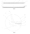
Figure 1 is a sectional view of a cylinder body of an actuating cylinder according to an embodiment of the present invention; -
Figure 2 is a partially enlarged view of part A shown inFigure 1 ; -
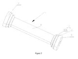
Figure 3 is a schematic diagram of the overall structure of the inner lining layer of the cylinder body of an actuating cylinder shown inFigure 1 . -
1 inner lining layer; 2 first fibrous composite layer; 3 insulating layer; 4 second fibrous composite layer; 11 middle part; 12 end part; 13 transition part; 131 ramp part; 132 raised part - Hereunder the embodiments of the present invention will be detailed, with reference to the accompanying drawings. It should be appreciated that the embodiments described here are only provided to describe and explain the present invention, but shall not be deemed as constituting any limitation to the present invention. As shown in
Figure 1 and Figure 2 , in an embodiment, the present invention provides a cylinder body of an actuating cylinder, which comprises an inner lining layer 1 and a first fibrouscomposite layer 2 bonded on the outside of the inner lining layer 1. - In the above technical scheme, the cylinder body of an actuating cylinder comprises an inner lining layer 1 and a first fibrous
composite layer 2; owing to the fact that the fibrous composite has lighter weight when compared with existing metallic materials with the same strength as well as has high fatigue resistance, high corrosion resistance and low thermal expansibility, the cylinder body of an actuating cylinder has high strength, light weight, high fatigue resistance, high corrosion resistance and low thermal expansibility; therefore, the actuating cylinder can be applied more widely. In addition, since the inner lining layer of the cylinder body can meet the requirements for leak tightness of the inner wall of cylinder body and wear resistance when contacts with the piston, the service performance of the cylinder body will not be degraded. The inner lining layer 1 may be made of an appropriate material that can meet the requirements for leak tightness of the inner wall of cylinder body and wear resistance when contacts with the piston; for example, the inner lining layer 1 may be made of an existing metallic material that is usually used to manufacture a cylinder body. - The fibrous composite material mentioned in the present invention (e.g., the fibrous composite material of the first fibrous
composite layer 2 or second fibrous composite layer 4) refers to a material composited from a fibrous material and a substrate resin material, i.e., a fiber reinforced resin composite material. - The first
fibrous composite layer 2 may be composited from any appropriate fibrous material and substrate resin material; for example, the fibrous material may be selected from one or more of fiber glass, aramid fiber, super-high molecular weight polyethylene fiber and carbon fiber. Preferably, the firstfibrous composite layer 2 is made of a carbon fiber material and a substrate resin material. Carbon fiber composite materials have advantages such as light weight, high strength, high rigidity, high damping performance, high fatigue resistance, high corrosion resistance, etc. The carbon fiber material may be composited with a variety of substrate resin materials to form carbon fiber composite materials; for example, the substrate resin material may be unsaturated polyester, vinyl resin, phenolic resin, etc., preferably an epoxy resin system that has good machinability, high strength and high ductility. Among the fibrous materials that can be used to form the first fibrouscomposite layer 2, some are electroconductive materials, and others are non-electroconductive materials; in case the inner lining layer 1 and the first fibrouscomposite layer 2 are made of electroconductive materials (e.g., the inner lining layer 1 is made of a metallic material, and the first fibrous composite layer is made of a carbon fiber composite material), aninsulating layer 3 is preferably arranged between the inner lining layer 1 and the first fibrouscomposite layer 2. Thus, the electro-chemical corrosion between the inner lining layer 1 and the first fibrouscomposite layer 2 can be prevented, and the service life of the cylinder body of an actuating cylinder can be prolonged. The insulatinglayer 3 may be made of any appropriate insulating material; for example, it may be selected from one or more of fiber glass, aramid fiber, super-high molecular weight polyethylene fiber and basalt fiber. For example, theinsulating layer 3 may be bonded to the inner lining layer 1 by a high-toughness adhesive. - Preferably, as shown in
Figure 1 and Figure 2 , a second fibrous composite layer 4 is arranged on the outside of the firstfibrous composite layer 2. The second fibrous composite layer 4 is helpful for improving impact resistance of the cylinder body against external impacts. The second fibrous composite layer 4 may be composited from any appropriate fibrous material and substrate resin material; for example, the fibrous material may be selected from one or more of fiber glass, aramid fiber, super-high molecular weight polyethylene fiber and basalt fiber. The substrate resin material for the first fibrouscomposite layer 2 may be identical to or different from the substrate resin material for the second fibrous composite layer 4. - The present invention doesn't involve any change to the overall shape of the cylinder body of an actuating cylinder, which is to say, the overall shape of the cylinder body of an actuating cylinder may be identical to the overall shape of the cylinder body of any existing actuating cylinder; for example, the cylinder body of an actuating cylinder may be generally in a hollow cylinder structure, with connecting thread and/or an oil port arranged on both ends, wherein, the connecting thread is mainly designed to connect an end cap of the actuating cylinder, and the oil port is mainly designed to connect a working oil circuit of the actuating cylinder, so that the working oil circuit can communicate with a working chamber within the cylinder body. The main innovative ideal of the present invention lies in: the cylinder body comprises multiple material layers, so as to improve the strength, corrosion resistance and fatigue resistance of the cylinder body and decrease the weight and thermal expansibility of the cylinder body. The multiple material layers of the cylinder body (e.g., the above-mentioned inner lining layer 1, first fibrous
composite layer 2,insulating layer 3 and second fibrous composite layer 4) may have even thickness or uneven thickness respectively. Preferably, as shown inFigure 1∼3 , the inner lining layer 1 is generally in a cylindrical shape, and comprises amiddle part 11 and twoend parts 12 at the sides of themiddle part 11, wherein, the thickness of themiddle part 11 is smaller than the thickness of eachend part 12. Themiddle part 11 and twoend parts 12 are arranged essentially along the axial direction of the cylinder body, and the inner lining layer 1 is essentially in a structure that is bigger at both ends and smaller in the middle, which is helpful for processing and port arrangement, and provides fixing effect for the fibrous composite material formed on the outside of the twoend parts 12 and themiddle part 11. - More preferably, a
transition part 13 is arranged between eachend part 12 and themiddle part 11, and the thickness of thetransition part 13 transits from the thickness of theend part 12 to the thickness of themiddle part 11. With thetransition part 13, stress concentration incurred by abrupt change of thickness can be prevented. - Preferably, an oil port and/or connecting thread is/are arranged on the
end parts 12 of the inner lining layer 1, and the first fibrouscomposite layer 2 is arranged on the outside of themiddle part 11 andtransition part 13 of the inner lining layer 1. Thus, the oil port and/or connecting thread of the cylinder body can be pre-formed on theend parts 12 as required, and the oil part and/or connecting thread is/are not covered by the first fibrouscomposite layer 2, insulatinglayer 3 and second fibrous composite layer 4 (if any); therefore, the cylinder body has high machinability, and it is unnecessary to work out additional oil port and/or connecting thread on any other material layer (e.g., the first fibrouscomposite layer 2,insulating layer 3 and second fibrous composite layer 4) except for the inner lining layer 1. - The
transition part 13 may have a ramp profile with uniformly transiting thickness, or a staged profile with thickness transiting by stages, or any other appropriate profile. More preferably, as shown inFigure 1∼3 , thetransition part 13 comprises aramp part 131 and araised part 132 arranged on theramp part 131, wherein, the thickness of theramp part 131 transits uniformly from the thickness of theend part 12 to the thickness of themiddle part 11. The raisedpart 132 is helpful for bonding between the inner lining layer 1 and other material layers (e.g., the first fibrous composite layer 2) and improving the bonding force, and can prevent the inner lining layer 1 from separated from other material layers. Theraised part 132 may be one raised continuous ring or multiple raised continuous rings (one continuous ring as shown inFigure 3 ), or may be a plurality of discrete raised bars or raised ribs. - In another aspect, the present invention provides a concrete pumping apparatus, wherein, a cylinder body of a pumping cylinder of the concrete pumping apparatus is the cylinder body of an actuating cylinder described above.
- In another aspect, the present invention provides a method of manufacturing a cylinder body of an actuating cylinder, comprising: an inner lining layer forming step: forming an inner lining layer 1; and, a bonding step: forming a first fibrous
composite layer 2 with a first fibrous material and a substrate resin material and bonding the first fibrouscomposite layer 2 on the outside of the inner lining layer 1. - In the above technical scheme, the cylinder body of an actuating cylinder comprises an inner lining layer 1 and a first fibrous
composite layer 2; owing to the fact that the fibrous composite has lighter weight when compared with existing metallic materials with the same strength as well as has high fatigue resistance, high corrosion resistance and low thermal expansibility, the cylinder body of an actuating cylinder has high strength, light weight, high fatigue resistance, high corrosion resistance and low thermal expansibility; therefore, the actuating cylinder can be applied more widely. In addition, since the inner lining layer of the cylinder body can meet the requirements for leak tightness of the inner wall of cylinder body and wear resistance when contacts with the piston, the service performance of the cylinder body will not be degraded. The inner lining layer 1 may be made of an appropriate material that can meet the requirements for leak tightness of the inner wall of cylinder body and wear resistance when contacts with the piston; for example, the inner lining layer 1 may be made of an existing metallic material that is usually used to manufacture a cylinder body. - The first fibrous
composite layer 2 may be composited from any appropriate fibrous material and substrate resin material; for example, the fibrous material may be selected from one or more of fiber glass, aramid fiber, super-high molecular weight polyethylene fiber and carbon fiber. Preferably, in the bonding step, the first fibrouscomposite layer 2 is formed from a carbon fiber and a substrate resin. Carbon fiber composite materials have advantages such as light weight, high strength, high rigidity, high damping performance, high fatigue resistance, high corrosion resistance, etc. The carbon fiber material may be composited with a variety of substrate resin materials to form carbon fiber composite materials; for example, the substrate resin material may be unsaturated polyester, vinyl resin, phenolic resin, etc., preferably an epoxy resin system that has good machinability, high strength and high ductility. Among the fibrous materials that can be used to form the first fibrouscomposite layer 2, some are electroconductive materials, and others are non-electroconductive materials. Preferably, in the inner lining layer forming step, the inner lining layer 1 is formed from a electroconductive material (e.g., a metallic material, more specifically, 27SiMn); in the bonding step, the first fibrouscomposite layer 2 is formed from a electroconductive material (e.g., a carbon fiber composite material); in addition, the manufacturing method further comprises an insulating layer forming step: forming an insulatinglayer 3 on the outside of the inner lining layer 1 before the bonding step, so that the insulatinglayer 3 is arranged between the inner lining layer 1 and the first fibrouscomposite layer 2. Thus, the electro-chemical corrosion between the inner lining layer 1 and the first fibrouscomposite layer 2 can be prevented, and the service life of the cylinder body of an actuating cylinder can be prolonged. The insulatinglayer 3 may be made of any appropriate insulating material; for example, it may be selected from one or more of fiber glass, aramid fiber, super-high molecular weight polyethylene fiber and basalt fiber. For example, the insulating layer may be formed by wrapping a piece of fiber cloth (e.g., glass fiber cloth) on the outside of the inner lining layer 1. For example, the insulatinglayer 3 may be bonded to the inner lining layer 1 by a high-toughness adhesive. - The first fibrous composite layer may be formed and bonded in an appropriate manner; preferably, in the bonding step, a bundle of the first fibrous material dipped with the substrate resin is wound on the outside of the inner lining layer 1 by a wet winding process. Specifically, a bundle of continuous first fiber is dipped with prepared epoxy resin, and then wound to the fixed inner lining layer 1 through a winding guide head of a winding machine, so as to accomplish fiber winding. A product obtained by wet winding gives full play to the properties of the composite material; therefore, the product is afforded with required structural performance as far as possible, and the forming cost is low and the process is relatively simple.
- More preferably, when the bundle of the first fibrous composite material is wound, the angle between the extension direction of the bundle of the first fibrous composite material and the axial line of the cylinder body is 70°∼90°, i.e., the winding angle of the first fibrous composite material is 70°∼90°. Owing to the fact that the stress on the cylinder body in radial direction is usually 2-3 times of the stress on the cylinder body in circumferential direction, the wrapping angle is helpful for improving the radial strength of the cylinder body (i.e., improving the mechanical properties of the cylinder body) and reducing the overall thickness of the cylinder body, and thereby can provide favorable fatigue resistance performance for the cylinder body. Preferably, the manufacturing method further comprises: forming a second fibrous composite layer 4 on the outside of the first fibrous
composite layer 2. The second fibrous composite layer 4 is helpful for improving impact resistance of the cylinder body against external impacts. The second fibrous composite layer 4 may be composited from any appropriate fibrous material and substrate resin material; for example, the fibrous material may be selected from one or more of fiber glass, aramid fiber, super-high molecular weight polyethylene fiber and basalt fiber. For example, the second fibrous composite layer 4 may be formed by wrapping a piece of cloth made of a second fibrous material on the outside of the first fibrouscomposite layer 2 so as to make the substrate resin in the first fibrouscomposite layer 2 infiltrate into the cloth made of a second fibrous material. Of course, when the second fibrous composite layer 4 is formed, substrate resin may be added on the second fibrous material cloth additionally, instead of utilizing the substrate resin in the first fibrouscomposite layer 2. - The present invention doesn't involve any change to the overall shape of the cylinder body of an actuating cylinder, which is to say, the overall shape of the cylinder body of an actuating cylinder may be identical to the overall shape of the cylinder body of any existing actuating cylinder; for example, the cylinder body of an actuating cylinder may be generally in a hollow cylinder structure, with connecting thread and/or an oil port arranged on both ends. The main innovative ideal of the present invention lies in: the cylinder body comprises multiple material layers, so as to improve the strength, corrosion resistance and fatigue resistance of the cylinder body and decrease the weight and thermal expansibility of the cylinder body. The multiple material layers of the cylinder body (e.g., the above-mentioned inner lining layer 1, first fibrous
composite layer 2, insulatinglayer 3 and second fibrous composite layer 4) may have even thickness or uneven thickness respectively. Preferably, the inner lining layer forming step comprises: providing a blank of the inner lining layer that is generally in a hollow cylinder shape; and, a machining procedure: reducing the thickness of a part of the blank of the inner lining layer by machining (e.g., turning), so that the inner lining layer 1 is formed to have amiddle part 11 and twoend parts 12 at the sides of themiddle part 11, wherein, the thickness of themiddle part 11 is smaller than the thickness of eachend part 12. Themiddle part 11 and twoend parts 12 are arranged essentially along the axial direction of the cylinder body, and the inner lining layer 1 is essentially in a structure that is bigger at both ends and smaller in the middle which is helpful for processing and port arrangement, and provides fixing effect for the fibrous composite material formed on the outside of the twoend parts 12 and themiddle part 11. - More preferably, in the machining procedure, a
transition part 13 is formed between eachend part 12 and themiddle part 11, and the thickness of thetransition part 13 transits from the thickness of theend part 12 to the thickness of themiddle part 11. With thetransition part 13, stress concentration incurred by abrupt change of thickness can be prevented. - More preferably, in the inner lining layer forming step, an oil port and/or connecting thread is/are formed on the
end parts 12 of the inner lining layer 1, and in the bonding step, the first fibrouscomposite layer 2 is bonded on the outside of themiddle part 11 andtransition parts 13 of the inner lining layer 1. Thus, the oil port and/or connecting thread of the cylinder body can be pre-formed on theend parts 12 as required, and the oil part and/or connecting thread is/are not covered by the first fibrouscomposite layer 2, insulatinglayer 3 and second fibrous composite layer 4 (if any); therefore, the cylinder body has high machinability, and it is unnecessary to work out additional oil port and/or connecting thread on any other material layer (e.g., the first fibrouscomposite layer 2, insulatinglayer 3 and second fibrous composite layer 4) except for the inner lining layer 1. - The
transition part 13 may have a ramp profile with uniformly transiting thickness or a staged profile with thickness transiting by stages, or any other appropriate profile. Preferably, in the machining procedure, thetransition part 13 is formed to have aramp part 131 and a raisedpart 132 arranged on theramp part 131, wherein, the thickness of theramp part 131 transits uniformly from the thickness of theend part 12 to the thickness of themiddle part 11. The raisedpart 132 is helpful for bonding between the inner lining layer 1 and other material layers (e.g., the first fibrous composite layer 2) and improving the bonding force, and can prevent the inner lining layer 1 from separated from other material layers. The raisedpart 132 may be one raised continuous ring or multiple raised continuous rings (one continuous ring as shown inFigure 3 ), or may be a plurality of discrete raised bars or raised ribs. - More preferably, the inner lining layer forming step further comprises: a sand blasting procedure: carrying out sand blasting on the outer surface of the inner lining layer 1 formed in the machining procedure, to increase roughness of the outer surface of the inner lining layer 1. In that way, the bonding force between the inner lining layer 1 and other material layers (e.g., insulating
layer 3, first fibrouscomposite layer 2, etc.) can be increased. - Hereunder the manufacturing process of the cylinder body will be described briefly taking the embodiment of cylinder body of an actuating cylinder shown in
Figure 1∼3 as an example. - (1) Forming the inner lining layer 1 shown in
Figure 3 by machining; - (3) Bonding a piece of glass fiber cloth on the outside of the
middle part 11 of the inner lining layer 1 by a high-toughness adhesive, to form an insulatinglayer 3; - (3) Forming a first fibrous
composite layer 2 on the outside of the insulatinglayer 3 and thetransition part 13 of the inner lining layer 1 by wet winding; - (4) Wrapping a piece of glass fiber cloth on the outside of the first fibrous
composite layer 2 so as to control the substrate resin in the first fibrouscomposite layer 2 infiltrate into the glass fiber cloth, to form a second fibrous composite layer 4; - (5) Loading the cylinder body into a baking oven, to accomplish forming by thermosetting.
- The cylinder body of an actuating cylinder and the method of manufacturing the cylinder body described above are applicable to different types of actuating cylinders, including hydraulic cylinders, gas cylinders, etc.; for example, the cylinder body may be widely used as a cylinder body of an actuating cylinder in different engineering machines, such as concrete pump trucks, lifters, excavators, fire engines, overhead working trucks, environmental sanitation vehicles, etc.
- While some preferred embodiments of the present invention are described above with reference to the accompanying drawings, the present invention is not limited to the details in those embodiments. Those skilled in the art can make modifications and variations to the technical scheme of the present invention, without departing from the spirit of the present invention. However, all these modifications and variations shall be deemed as falling into the protected domain of the present invention.
- In addition, it should be appreciated that the technical features described in the above embodiments can be combined in any appropriate manner, provided that there is no conflict among the technical features in the combination. To avoid unnecessary iteration, such possible combinations will not be described here in the present invention.
- Moreover, the different embodiments of the present invention can be combined freely as required, as long as the combinations don't deviate from the ideal and spirit of the present invention. However, such combinations shall also be deemed as falling into the scope disclosed in the present invention.
Claims (23)
- A cylinder body of an actuating cylinder, comprising an inner lining layer (1) and a first fibrous composite layer (2) bonded on the outside of the inner lining layer (1), wherein the first fibrous composite layer (2) is composited from a first fibrous material and a substrate resin material.
- The cylinder body of an actuating cylinder according to claim 1, wherein, the inner lining layer (1) is made of a metallic material.
- The cylinder body of an actuating cylinder according to claim 1, wherein, the inner lining layer (1) and the first fibrous composite layer (2) are made of a electroconductive material, and an insulating layer (3) is arranged between the inner lining layer (1) and the first fibrous composite layer (2).
- The cylinder body of an actuating cylinder according to claim 1, wherein, the first fibrous composite layer (2) is composited from a carbon fiber material and a substrate resin material.
- The cylinder body of an actuating cylinder according to claim 1, wherein, a second fibrous composite layer (4) is arranged on the outside of the first fibrous composite layer (2), and the second fibrous composite layer (4) is composited from a second fibrous material and a substrate resin material.
- The cylinder body of an actuating cylinder according to any of claims 1∼5, wherein, the inner lining layer (1) is generally in a cylindrical shape, and comprises a middle part (11) and two end parts (12) at the sides of the middle part (11), and the thickness of the middle part (11) is smaller than the thickness of each end part (12).
- The cylinder body of an actuating cylinder according to claim 6, wherein, a transition part (13) is respectively arranged between each end part (12) and the middle part (11), and the thickness of the transition part (13) transits from the thickness of the end part (12) to the thickness of the middle part (11).
- The cylinder body of an actuating cylinder according to claim 7, wherein, the transition part (13) comprises a ramp part (131) and a raised part (132) arranged on the ramp part (131), and the thickness of the ramp part (131) transits uniformly from the thickness of the end part (12) to the thickness of the middle part (11).
- The cylinder body of an actuating cylinder according to claim 7, wherein, an oil port and/or connecting thread is/are arranged on the end parts (12) of the inner lining layer (1), and the first fibrous composite layer (2) is arranged on the outside of the middle part (11) and the transition part (13) of the inner lining layer (1).
- A concrete pumping apparatus, wherein, a cylinder body of a pumping cylinder of the concrete pumping apparatus is the cylinder body of an actuating cylinder as set forth in any of claims 1∼9.
- A method of manufacturing a cylinder body of an actuating cylinder, comprising:an inner lining layer forming step: forming an inner lining layer (1); anda bonding step: forming a first fibrous composite layer (2) composited from a first fibrous material and a substrate resin material, and bonding the first fibrous composite layer (2) on the outside of the inner lining layer (1).
- The method of manufacturing a cylinder body of an actuating cylinder according to claim 11, wherein, in the inner lining layer forming step, the inner lining layer (1) is formed from a metallic material.
- The method of manufacturing a cylinder body of an actuating cylinder according to claim 11, wherein:in the inner lining layer forming step, the inner lining layer (1) is formed from a electroconductive material;in the bonding step, the first fibrous composite layer (2) is formed from a electroconductive material; andthe method further comprises an insulating layer forming step: forming an insulating layer (3) on the outside of the inner lining layer (1) before the bonding step, so that the insulating layer (3) is arranged between the inner lining layer (1) and the first fibrous composite layer (2).
- The method of manufacturing a cylinder body of an actuating cylinder according to claim 11, wherein, in the bonding step, the first fibrous composite layer (2) is composited from a carbon fiber material and a substrate resin material.
- The method of manufacturing a cylinder body of an actuating cylinder according to claim 11, wherein, in the bonding step, a bundle of the first fibrous material dipped with the substrate resin is wound on the outside of the inner lining layer (1) by a wet winding process.
- The method of manufacturing a cylinder body of an actuating cylinder according to claim 15, wherein, when the bundle of first fibrous material is wound, the angle between the extension direction of the bundle of the first fibrous material and the axial direction of the cylinder body is 70°∼90°.
- The method of manufacturing a cylinder body of an actuating cylinder according to claim 11, further comprising: forming a second fibrous composite layer (4) on the outside of the first fibrous composite layer (2).
- The method of manufacturing a cylinder body of an actuating cylinder according to claim 17, wherein, the second fibrous composite layer (4) is formed by wrapping a piece of cloth made of a second fibrous material on the outside of the first fibrous composite layer (2) so as to make the substrate resin in the first fibrous composite layer (2) infiltrate into the cloth made of a second fibrous material.
- The method of manufacturing a cylinder body of an actuating cylinder according to any of claims 11∼18, wherein, the inner lining layer forming step comprises:providing a blank of the inner lining layer that is generally in a hollow cylinder shape; anda machining procedure: reducing the thickness of a part of the blank of the inner lining layer by machining, so that the inner lining layer (1) is formed to have a middle part (11) and two end parts (12) at the sides of the middle part (11), wherein, the thickness of the middle part (11) is smaller than the thickness of each end part (12).
- The method of manufacturing a cylinder body of an actuating cylinder according to claim 19, wherein, in the machining procedure, a transition part (13) is respectively formed between each end part (12) and the middle part (11), and the thickness of the transition part (13) transits from the thickness of the end part (12) to the thickness of the middle part (11).
- The method of manufacturing a cylinder body of an actuating cylinder according to claim 20, wherein, in the machining procedure, the transition part (13) is formed to have a ramp part (131) and a raised part (132) arranged on the ramp part (131), and the thickness of the ramp part (131) transits uniformly from the thickness of the end part (12) to the thickness of the middle part (11).
- The method of manufacturing a cylinder body of an actuating cylinder according to claim 20, wherein, the inner lining layer forming step further comprises a sand blasting procedure, in the sand blasting procedure, carrying out sand blasting on the outer surface of the inner lining layer (1) formed in the machining procedure, to increase roughness of the outer surface of the inner lining layer (1).
- The method of manufacturing a cylinder body of an actuating cylinder according to claim 19, wherein:in the inner lining layer forming step, an oil port and/or connecting thread is/are formed on the end parts (12) of the inner lining layer (1);in the bonding step, the first fibrous composite layer (2) is bonded on the outside of the middle part (11) and transition parts (13) of the inner lining layer (1).
Applications Claiming Priority (2)
| Application Number | Priority Date | Filing Date | Title |
|---|---|---|---|
| CN201210195986.3A CN102705293B (en) | 2012-06-14 | 2012-06-14 | Cylinder body of actuating cylinder, manufacturing method thereof, and concrete pumping equipment |
| PCT/CN2012/086108 WO2013185451A1 (en) | 2012-06-14 | 2012-12-07 | Method for manufacturing cylinder body of actuating cylinder and concrete pumping apparatus |
Publications (1)
| Publication Number | Publication Date |
|---|---|
| EP2749776A1 true EP2749776A1 (en) | 2014-07-02 |
Family
ID=46898285
Family Applications (1)
| Application Number | Title | Priority Date | Filing Date |
|---|---|---|---|
| EP12878834.6A Withdrawn EP2749776A1 (en) | 2012-06-14 | 2012-12-07 | Method for manufacturing cylinder body of actuating cylinder and concrete pumping apparatus |
Country Status (4)
| Country | Link |
|---|---|
| EP (1) | EP2749776A1 (en) |
| CN (1) | CN102705293B (en) |
| IN (1) | IN2014KN00740A (en) |
| WO (1) | WO2013185451A1 (en) |
Cited By (2)
| Publication number | Priority date | Publication date | Assignee | Title |
|---|---|---|---|---|
| DE102015224913A1 (en) * | 2015-12-10 | 2017-06-14 | Festo Ag & Co. Kg | fluid actuator |
| EP3260369A1 (en) * | 2016-06-23 | 2017-12-27 | Goodrich Corporation | Metallic composite joint |
Families Citing this family (12)
| Publication number | Priority date | Publication date | Assignee | Title |
|---|---|---|---|---|
| CN102705293B (en) * | 2012-06-14 | 2014-04-09 | 中联重科股份有限公司 | Cylinder body of actuating cylinder, manufacturing method thereof, and concrete pumping equipment |
| CN102689436A (en) * | 2012-06-14 | 2012-09-26 | 中联重科股份有限公司 | Method for manufacturing a cylinder block of an actuating cylinder |
| CN103470755B (en) * | 2013-09-11 | 2015-12-23 | 中联重科股份有限公司 | Piston cylinder and manufacturing method of piston cylinder |
| CN103727092A (en) * | 2014-01-24 | 2014-04-16 | 武汉理工大学 | Hydraulic cylinder of carbon fiber composite material |
| JP6368517B2 (en) * | 2014-03-28 | 2018-08-01 | Kyb株式会社 | Hydraulic rotating machine |
| CN104832487A (en) * | 2014-09-18 | 2015-08-12 | 北汽福田汽车股份有限公司 | Cylinder barrel transition connector of driving cylinder and driving cylinder with cylinder barrel transition connector |
| CN104454763B (en) * | 2014-12-02 | 2017-01-04 | 荣成复合材料有限公司 | A kind of composite hydraulic jack or the manufacture method of telescopic arm |
| CN105587709B (en) * | 2016-03-17 | 2018-03-06 | 中联重科股份有限公司 | Hydraulic cylinder |
| CN106930998A (en) * | 2017-05-18 | 2017-07-07 | 武汉科技大学 | A kind of enhanced lightweight hydraulic cylinder of carbon fibre composite |
| CN108953600A (en) * | 2018-06-26 | 2018-12-07 | 河南德佰特机电设备制造有限公司 | A kind of cylinder barrel reducing weight |
| CN109340209B (en) * | 2018-10-29 | 2020-11-27 | 山西平阳重工机械有限责任公司 | Carbon fiber double telescopic cylinder for motor vehicle rescue |
| CN111590916A (en) * | 2020-04-24 | 2020-08-28 | 哈尔滨新科锐复合材料制造有限公司 | Inner shell of sound generator made of carbon fiber composite material for police |
Family Cites Families (14)
| Publication number | Priority date | Publication date | Assignee | Title |
|---|---|---|---|---|
| US3793104A (en) * | 1972-03-31 | 1974-02-19 | Lawron Ind Ltd | Process for restoring and covering suction couch shells |
| US4867044A (en) * | 1984-11-26 | 1989-09-19 | The United States Of America As Represented By The Secretary Of The Navy | Jam resistant fluid power actuator for ballistic-damage tolerant redundant cylinder assemblies |
| US4971846A (en) * | 1987-11-16 | 1990-11-20 | Tre Corporation | Thermoplastic cylinder and process for manufacturing same |
| JPH0634047A (en) * | 1992-07-15 | 1994-02-08 | Sumitomo Metal Ind Ltd | Cylinder device |
| DE19649133C1 (en) * | 1996-11-27 | 1998-03-05 | Dornier Gmbh | Hydraulic cylinder |
| AT502447B1 (en) * | 2004-11-25 | 2007-06-15 | Hoelzl Margit | CYLINDERS FOR HIGH-PRESSURE HYDRAULICS |
| JP4874326B2 (en) * | 2005-03-22 | 2012-02-15 | クイックステップ、テクノロジーズ、プロプライエタリ、リミテッド | Manufacture of composite tube |
| JP4669318B2 (en) * | 2005-05-11 | 2011-04-13 | カヤバ工業株式会社 | Cylinder barrel |
| CN101362387A (en) * | 2007-08-10 | 2009-02-11 | 武济群 | Method for manufacturing composite pipe |
| CN101900246B (en) * | 2010-07-28 | 2011-09-07 | 国营江北机械厂 | Solidification method of fiber-wound gas cylinder |
| CN102689436A (en) * | 2012-06-14 | 2012-09-26 | 中联重科股份有限公司 | Method for manufacturing a cylinder block of an actuating cylinder |
| CN102705293B (en) * | 2012-06-14 | 2014-04-09 | 中联重科股份有限公司 | Cylinder body of actuating cylinder, manufacturing method thereof, and concrete pumping equipment |
| CN202597323U (en) * | 2012-06-14 | 2012-12-12 | 中联重科股份有限公司 | Cylinder body of actuating cylinder and concrete pumping equipment |
| CN102720721A (en) * | 2012-07-02 | 2012-10-10 | 江苏恒神纤维材料有限公司 | Carbon fiber composite material reinforcing hydraulic oil cylinder |
-
2012
- 2012-06-14 CN CN201210195986.3A patent/CN102705293B/en active Active
- 2012-12-07 IN IN740KON2014 patent/IN2014KN00740A/en unknown
- 2012-12-07 WO PCT/CN2012/086108 patent/WO2013185451A1/en not_active Ceased
- 2012-12-07 EP EP12878834.6A patent/EP2749776A1/en not_active Withdrawn
Non-Patent Citations (1)
| Title |
|---|
| See references of WO2013185451A1 * |
Cited By (4)
| Publication number | Priority date | Publication date | Assignee | Title |
|---|---|---|---|---|
| DE102015224913A1 (en) * | 2015-12-10 | 2017-06-14 | Festo Ag & Co. Kg | fluid actuator |
| DE102015224913B4 (en) | 2015-12-10 | 2023-12-21 | Festo Se & Co. Kg | Fluid actuator |
| EP3260369A1 (en) * | 2016-06-23 | 2017-12-27 | Goodrich Corporation | Metallic composite joint |
| US10272991B2 (en) | 2016-06-23 | 2019-04-30 | Goodrich Corporation | Metallic composite joint |
Also Published As
| Publication number | Publication date |
|---|---|
| CN102705293A (en) | 2012-10-03 |
| IN2014KN00740A (en) | 2015-10-02 |
| CN102705293B (en) | 2014-04-09 |
| WO2013185451A1 (en) | 2013-12-19 |
Similar Documents
| Publication | Publication Date | Title |
|---|---|---|
| CN102705293B (en) | Cylinder body of actuating cylinder, manufacturing method thereof, and concrete pumping equipment | |
| EP2963313A1 (en) | Gear made from first and second materials | |
| WO2002068844A1 (en) | Pump liner | |
| CN105074245B (en) | Bushing with dual structure and bearing assembly with the bushing | |
| KR102181843B1 (en) | Torsion-loaded rod-shaped component with different fibre reinforcements for tensile and compressive loading | |
| JP4669318B2 (en) | Cylinder barrel | |
| US20050089429A1 (en) | Composite material progressing cavity stators | |
| US20190310044A1 (en) | Metal-Metal-Matrix Composite Barrels | |
| US11193535B2 (en) | Ring with composite and metal two material squirrel type cage, and bearing assembly with rolling elements that is equipped with such a ring | |
| US20180335077A1 (en) | Shaft and method for manufacturing a shaft | |
| JP2019019008A (en) | Method of repairing ceramic matrix composite, and ceramic matrix composite | |
| US8261767B1 (en) | Powdered metal inlay | |
| US20150226329A1 (en) | Hydraulic cylinder made of hybrid composite laminate, in particular for high-power applications | |
| CN102689436A (en) | Method for manufacturing a cylinder block of an actuating cylinder | |
| US6675699B1 (en) | Composite components for use in pumps | |
| WO2000077347A1 (en) | Pump liner | |
| KR100715427B1 (en) | Lightweight boom assembly made of composite and metal | |
| KR20180023798A (en) | Light hydraulic cylinder using carbon-fiber | |
| CN102996566A (en) | Cylinder body of actuating cylinder, manufacturing method thereof, and concrete pumping equipment | |
| CN103470755B (en) | Piston cylinder and manufacturing method of piston cylinder | |
| JP2021092173A (en) | Cylinder block | |
| US9409376B2 (en) | Reinforcement integrated into the structure of wound components consisting of composite materials | |
| KR102239093B1 (en) | Composite material for reinforcement and articles comprising the same | |
| KR102074189B1 (en) | Hybrid round bar and manufacturing method thereof | |
| CN211343584U (en) | Embedded combined cylinder structure of prestressing force |
Legal Events
| Date | Code | Title | Description |
|---|---|---|---|
| PUAI | Public reference made under article 153(3) epc to a published international application that has entered the european phase |
Free format text: ORIGINAL CODE: 0009012 |
|
| 17P | Request for examination filed |
Effective date: 20140326 |
|
| AK | Designated contracting states |
Kind code of ref document: A1 Designated state(s): AL AT BE BG CH CY CZ DE DK EE ES FI FR GB GR HR HU IE IS IT LI LT LU LV MC MK MT NL NO PL PT RO RS SE SI SK SM TR |
|
| STAA | Information on the status of an ep patent application or granted ep patent |
Free format text: STATUS: THE APPLICATION HAS BEEN WITHDRAWN |
|
| 18W | Application withdrawn |
Effective date: 20150501 |