EP2749772A1 - Method for manufacturing machine component, and rotary machine equipped with impeller manufactured by means of this method - Google Patents
Method for manufacturing machine component, and rotary machine equipped with impeller manufactured by means of this method Download PDFInfo
- Publication number
- EP2749772A1 EP2749772A1 EP12859468.6A EP12859468A EP2749772A1 EP 2749772 A1 EP2749772 A1 EP 2749772A1 EP 12859468 A EP12859468 A EP 12859468A EP 2749772 A1 EP2749772 A1 EP 2749772A1
- Authority
- EP
- European Patent Office
- Prior art keywords
- base material
- strength
- heat treatment
- impeller
- machine component
- Prior art date
- Legal status (The legal status is an assumption and is not a legal conclusion. Google has not performed a legal analysis and makes no representation as to the accuracy of the status listed.)
- Granted
Links
Images






Classifications
-
- F—MECHANICAL ENGINEERING; LIGHTING; HEATING; WEAPONS; BLASTING
- F01—MACHINES OR ENGINES IN GENERAL; ENGINE PLANTS IN GENERAL; STEAM ENGINES
- F01D—NON-POSITIVE DISPLACEMENT MACHINES OR ENGINES, e.g. STEAM TURBINES
- F01D1/00—Non-positive-displacement machines or engines, e.g. steam turbines
- F01D1/18—Non-positive-displacement machines or engines, e.g. steam turbines without stationary working-fluid guiding means
-
- B—PERFORMING OPERATIONS; TRANSPORTING
- B23—MACHINE TOOLS; METAL-WORKING NOT OTHERWISE PROVIDED FOR
- B23P—METAL-WORKING NOT OTHERWISE PROVIDED FOR; COMBINED OPERATIONS; UNIVERSAL MACHINE TOOLS
- B23P15/00—Making specific metal objects by operations not covered by a single other subclass or a group in this subclass
- B23P15/006—Making specific metal objects by operations not covered by a single other subclass or a group in this subclass turbine wheels
-
- C—CHEMISTRY; METALLURGY
- C21—METALLURGY OF IRON
- C21D—MODIFYING THE PHYSICAL STRUCTURE OF FERROUS METALS; GENERAL DEVICES FOR HEAT TREATMENT OF FERROUS OR NON-FERROUS METALS OR ALLOYS; MAKING METAL MALLEABLE, e.g. BY DECARBURISATION OR TEMPERING
- C21D1/00—General methods or devices for heat treatment, e.g. annealing, hardening, quenching or tempering
- C21D1/26—Methods of annealing
- C21D1/30—Stress-relieving
-
- C—CHEMISTRY; METALLURGY
- C21—METALLURGY OF IRON
- C21D—MODIFYING THE PHYSICAL STRUCTURE OF FERROUS METALS; GENERAL DEVICES FOR HEAT TREATMENT OF FERROUS OR NON-FERROUS METALS OR ALLOYS; MAKING METAL MALLEABLE, e.g. BY DECARBURISATION OR TEMPERING
- C21D11/00—Process control or regulation for heat treatments
-
- F—MECHANICAL ENGINEERING; LIGHTING; HEATING; WEAPONS; BLASTING
- F04—POSITIVE - DISPLACEMENT MACHINES FOR LIQUIDS; PUMPS FOR LIQUIDS OR ELASTIC FLUIDS
- F04D—NON-POSITIVE-DISPLACEMENT PUMPS
- F04D29/00—Details, component parts, or accessories
- F04D29/02—Selection of particular materials
- F04D29/023—Selection of particular materials especially adapted for elastic fluid pumps
-
- F—MECHANICAL ENGINEERING; LIGHTING; HEATING; WEAPONS; BLASTING
- F04—POSITIVE - DISPLACEMENT MACHINES FOR LIQUIDS; PUMPS FOR LIQUIDS OR ELASTIC FLUIDS
- F04D—NON-POSITIVE-DISPLACEMENT PUMPS
- F04D29/00—Details, component parts, or accessories
- F04D29/26—Rotors specially for elastic fluids
- F04D29/28—Rotors specially for elastic fluids for centrifugal or helico-centrifugal pumps for radial-flow or helico-centrifugal pumps
- F04D29/281—Rotors specially for elastic fluids for centrifugal or helico-centrifugal pumps for radial-flow or helico-centrifugal pumps for fans or blowers
-
- C—CHEMISTRY; METALLURGY
- C21—METALLURGY OF IRON
- C21D—MODIFYING THE PHYSICAL STRUCTURE OF FERROUS METALS; GENERAL DEVICES FOR HEAT TREATMENT OF FERROUS OR NON-FERROUS METALS OR ALLOYS; MAKING METAL MALLEABLE, e.g. BY DECARBURISATION OR TEMPERING
- C21D2261/00—Machining or cutting being involved
-
- F—MECHANICAL ENGINEERING; LIGHTING; HEATING; WEAPONS; BLASTING
- F05—INDEXING SCHEMES RELATING TO ENGINES OR PUMPS IN VARIOUS SUBCLASSES OF CLASSES F01-F04
- F05D—INDEXING SCHEME FOR ASPECTS RELATING TO NON-POSITIVE-DISPLACEMENT MACHINES OR ENGINES, GAS-TURBINES OR JET-PROPULSION PLANTS
- F05D2230/00—Manufacture
- F05D2230/10—Manufacture by removing material
-
- F—MECHANICAL ENGINEERING; LIGHTING; HEATING; WEAPONS; BLASTING
- F05—INDEXING SCHEMES RELATING TO ENGINES OR PUMPS IN VARIOUS SUBCLASSES OF CLASSES F01-F04
- F05D—INDEXING SCHEME FOR ASPECTS RELATING TO NON-POSITIVE-DISPLACEMENT MACHINES OR ENGINES, GAS-TURBINES OR JET-PROPULSION PLANTS
- F05D2230/00—Manufacture
- F05D2230/40—Heat treatment
-
- Y—GENERAL TAGGING OF NEW TECHNOLOGICAL DEVELOPMENTS; GENERAL TAGGING OF CROSS-SECTIONAL TECHNOLOGIES SPANNING OVER SEVERAL SECTIONS OF THE IPC; TECHNICAL SUBJECTS COVERED BY FORMER USPC CROSS-REFERENCE ART COLLECTIONS [XRACs] AND DIGESTS
- Y10—TECHNICAL SUBJECTS COVERED BY FORMER USPC
- Y10T—TECHNICAL SUBJECTS COVERED BY FORMER US CLASSIFICATION
- Y10T29/00—Metal working
- Y10T29/49—Method of mechanical manufacture
- Y10T29/49764—Method of mechanical manufacture with testing or indicating
Definitions
- the present invention relates to a method for manufacturing a machine component, capable of determining based on simulation whether or not strength-related data (yield strength, hardness, etc.) predicted from the thickness of a base material such as an impeller material (machine component) meets required specifications, performing heat treatment of quenching and tempering based on results of the determination, and minimizing deformation of the base material in the event of heat treatment, and relates to a rotary machine equipped with an impeller manufactured by means of this method.
- strength-related data yield strength, hardness, etc.
- a welded impeller 10 formed in one body by mutually welding constituent members such as a cover 1, blades 2, and a disc 3 (showing weld zones with a symbol 4) is known.
- such a welded impeller 10 is manufactured, as shown in Fig. 11 , by independently preparing the cover (shroud) 1, the blades 2, and the disc (hub) 3 (S1), integrally forming these constituent members by weld zones 4 (S2), performing heat treatment such as quenching and tempering for the purpose of removing residual stress after the welding and enhancing hardness and durability (S3), performing finishing using mechanical working and electrical discharge machining (S4), and then performing trimming and polishing using electrolytic polishing and chemical polishing (S5).
- the impeller has made progress toward high efficiency and high performance, and a shape thereof has necessarily become complicated, diversified, and increased in precision.
- the heat treatment such as quenching and tempering for the purpose of removing residual stress after the welding and enhancing hardness and durability is performed (S3), but during the welding (S2) and the heat treatment (S3), deformation occurs leading to the possibility of dimensional precision being reduced.
- an integrated impeller (denoted by a symbol 11) integrally forming the cover, the blades, and the disc without being welded is provided.
- a cover (shroud) 5, blades 6, and a disc (hub) 7, which are main components, are manufactured from a metal serving as a base metal in a predetermined shape by mechanical working and electrical discharge machining, and are free from deformation caused by the welding. For this reason, a precise shape for obtaining desired performance as the impeller can be obtained, and no defects associated with the welding occur.
- the integrated impeller 11 is manufactured, as shown in Fig. 13 , by preparing the cover (shroud) 5, the blades 6, and the disc (hub) 7 from a material made of one block by means of cutting (S6), performing heat treatment for the purpose of hardening a surface and improving toughness (S7), performing finishing using mechanical working and electrical discharge machining (S8), and then performing trimming and polishing using electrolytic polishing and chemical polishing (S9).
- the process of hardening the surface to improve toughness by performing the heat treatment after the mechanical working is performed.
- a central portion C located in the center portion at which a cooling rate is slow
- the strength has a tendency to be lowered.
- a process of finishing such as grinding after the heat treatment may be required again to obtain desired dimensional precision.
- the present invention has been made in consideration of these circumstances, and an object of the present invention is to provide a method for manufacturing a machine component, capable of predicting strength in the event of heat treatment such as quenching and tempering to thereby reduce an amount of deformation of a base material to optimize a form in the event of the heat treatment, and improving performance of the machine component (impeller) used in a rotary machine, and a rotary machine equipped with an impeller manufactured by this method.
- a method for manufacturing a machine component in which a base material is subjected to a plurality of mechanical working processes and heat treatment processes and is processed into a final form.
- the method includes: a process of calculating and estimating post-heat-treatment strength for an intermediate form of the base material after one of the mechanical working processes is performed; and a process of comparing the estimated strength with reference strength required for the final form. According to a result of the comparison, heat treatment is performed after one of the mechanical working processes is performed.
- the process of estimating the post-heat-treatment strength for the intermediate form of the base material after one of the mechanical working processes is performed, and the process of comparing the estimated strength with the reference strength required for the final form are provided.
- the heat treatment of the base material is performed after one of the mechanical working processes is performed.
- processing of, for instance, changing the form of the base material is performed.
- required strength of the base material can be secured. That is, by reducing an amount of deformation of the base material in the event of the heat treatment to optimize the form in the event of the heat treatment, performance of the machine component (impeller) used in a rotary machine can be improved.
- finishing is performed after the heat treatment process.
- the base material hardened by quenching can be finished in the final form with a minimum amount of machining.
- the comparing process includes adjusting a thickness of the base material when the estimated strength does not meet the reference strength required for the final form.
- the comparing process includes forming the base material in a cylindrical form, in the center of which an opening is formed, when the estimated strength does not meet the reference strength required for the final form.
- the comparing process includes forming a cover profile on an outer surface of the base material formed in the cylindrical form when the estimated strength does not meet the reference strength required for the final form.
- the comparing process includes forming flow paths in the base material on which the cover profile is formed when the estimated strength does not meet the reference strength required for the final form.
- the comparing process when the estimated strength does not meet the reference strength required for the final form, various form changing processes of adjusting the thickness of the base material, forming the base material in the cylindrical form, in the center of which the opening is formed, forming the cover profile on the outer surface of the base material of the cylindrical form, and forming the flow paths in the base material on which the blades are formed are performed.
- the required strength of the base material can be reliably secured. That is, by appropriately changing the form of the base material, the form in the event of the heat treatment can be optimized so that hardening of the heat treatment is reliably reached to the central portion of the base material in the event of the heat treatment, and the performance of the machine component (impeller) used in the rotary machine can be improved.
- the rotary machine includes the impeller that is the machine component manufactured by the method relating to any one of the aspects, and a driving shaft that drives the impeller.
- a high-powered impeller manufactured by the manufacturing method is installed on the rotary machine such as a compressor.
- the rotary machine such as a compressor.
- the process of estimating the post-heat-treatment strength for the intermediate form of the base material after a mechanical working process is performed, and the process of comparing the estimated strength with the reference strength required for the final form are provided.
- the heat treatment of the base material is performed after a mechanical working process is performed.
- processing of, for instance, changing the form of the base material is performed.
- the required strength of the base material can be secured. That is, by reducing the amount of deformation of the base material in the event of the heat treatment to optimize the form in the event of the heat treatment, the performance of the machine component (impeller) used in the rotary machine can be improved.
- Fig. 1 is a process diagram schematically showing processes relating to a first embodiment of the present invention that shows timing of heat treatment in the present embodiment.
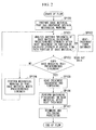
- Fig. 2 is a flowchart specifically showing the processes S10 to S 13 of Fig. 1 .
- an impeller material that has undergone certain mechanical working is prepared (S10).
- S10 an impeller material
- the present mechanical working cutting from a block of a solid material is illustrated.
- a metal block having, for example, a short column form or a truncated cone form is illustrated.
- heat treatment is performed based on conditions estimated by simulation (S11).
- heat treatment such as quenching and tempering is performed without changing a form of the material before flow path machining and profile machining are performed.
- the heat treatment is performed prior to cutting forms of the cover, the disc, and the blades, to make required material properties, thereby minimizing an influence which heat treatment deformation exerts on the final form.
- a thickness of the impeller material is set based on a target form of an impeller, and a cooling rate in the event of quenching is decided by a thickness of the impeller.
- hardness and strength yield strength
- yield strength yield strength
- the hardness and strength can be predicted using a continuous cooling transformation curve (CCT curve) shown in Fig. 4 and a tempering performance curve shown in Fig. 5 .
- Brinell hardness (HB) when the base material is cooled at 0.25 °C/sec becomes 518.
- HB Brinell hardness
- yield strength (YP) is about 70 kgf/mm 2 by a difference from a reference line B.
- a hardness difference ( ⁇ HB78) from the reference line A of the Brinell hardness (HB) corresponds to a strength difference ( ⁇ 26 kgf/mm 2 ) from the reference line B of the yield strength (YP), and a calculation is made based on this.
- the yield strength (YP) of the base material central portion which is obtained in this way is arranged from a relation between the cooling rate (°C/sec) and the thickness t (mm) of the base material 20, which is shown in Fig. 6 .
- the cooling rate of the central portion C is reduced. It is found that strength-related data (yield strength, hardness, etc.) achieved accordingly is also reduced.
- yield strength 90 kgf/mm 2
- the base material thickness t needs to be less than or equal to about 60 mm, and the cooling rate needs to be greater than or equal to 3 °C/sec.
- yield strength of 80 kgf/mm 2 the base material thickness t needs to be less than or equal to about 120 mm, and the cooling rate needs to be greater than or equal to 1 °C/sec.
- the cooling rate may be estimated using a method of evaluating the cooling rate with the aid of, for instance, a numerical simulation technique, or a method of directly measuring the cooling rate based on a test.
- the process After the mechanical working of, for instance, changing the thickness t of the base material 20 is performed based on the analysis result in SP101 (after a change in specification of, for instance, reducing the thickness of the base material 20 or changing to a thin material according to circumstances is performed), the process returns to SP101, and the strength of the base material after the heat treatment is estimated.
- the heat treatment of the base material 20 is performed.
- Trimming and polishing processing of, for instance, performing electrolytic polishing and chemical polishing is performed on the base material 20 machined in SP106.
- the method for manufacturing the machine component shown in the first embodiment has the processes SP 100 to SP102 of estimating post-heat-treatment strength for an intermediate form of the base material 20 after a certain mechanical working process, and the processes SP103 and SP104 of comparing the estimated strength with the required strength for the final form.
- the heat treatment of the base material 20 is performed after one of the aforementioned mechanical working processes (SP105 to SP107).
- SP105 to SP107 the aforementioned mechanical working processes
- processing of, for instance, changing the form of the base material 20 is performed (SP104).
- SP104 the required strength of the base material 20 can be secured.
- SP104 by reducing an amount of deformation of the base material 20 in the event of the heat treatment to optimize the form in the event of the heat treatment, it is possible to improve the performance of the machine component (impeller) used in the rotary machine.
- the electrical discharge machining is performed after the heat treatment process (SP105), and thereby even the base material 20 whose strength is increased can be easily machined.
- the mechanical working of, for instance, changing the thickness t of the base material 20 based on the analysis result of SP101 is performed in SP104.
- the second embodiment in addition to the thickness t of the base material 20, appropriate rough processing is performed depending on the thickness of the base material 20, and the overall form of the base material 20 is changed. Thereby, the heat treatment form is optimized.
- an initial form of the base material 20 is, as shown in Fig. 7A , a columnar block form (column material denoted by a symbol 20A).
- rough processing shaft hole drilling
- Fig. 7B rough processing
- Fig. 7B rough processing
- one of the form 20A to 20C in which the base material 20 is formed in SP104 is decided from the graph showing a relation between the cooling rate and the material thickness of each of the forms 20A to 20C shown in Fig. 8 .
- the forms 20A to 20C are selected, and the material thickness corresponding to the set cooling rate (3 °C/sec in the present embodiment) is decided from "the graph showing the relation between the cooling rate and the material thickness of each of the forms 20A to 20C" corresponding to the selected form.
- the material thickness that can only be about 60 mm in the form 20A can be selected up to about 85 mm if the form 20B is set, and up to 120 mm if the form 20C is set.
- the processing of changing to one of the forms 20A to 20C depending on the required strengths 70, 80, and 90 kgf/mm 2 in SP104 is performed, and then it is analyzed again whether the base material 20 actually meets the strength in SP101.
- the heat treatment form is optimized. That is, in the second embodiment, when the thickness of the impeller material 20 is relatively thick, the relation between the material thickness in the event of the rough-processing form, the cooling rate and the attained strength are previously arranged. Thereby, the optimal form is selected, and the heat treatment in which an amount of deformation is reduced as in the first embodiment can be performed.
- the heat treatment form is optimized.
- mechanical working flow path machining
- flow paths 21 may be adapted to be performed on the base material 20 (this is defined as a form 20D).
- the required strength in the event of the heat treatment is calculated from analysis results (deformation analysis result example) showing a degree of deformation of the base material 20 shown in Figs. 9B and 9C after the heat treatment. Further, in this case, the required strength in the event of the heat treatment is calculated in consideration of a relation between the cooling rate and the material thickness of the form 20D as well as a proper wall thickness of the material between the flow paths.
- the processing of changing the overall form of the base material 20 (from the form 20A to the forms 20B and 20C) and changing it to the form 20D in which the flow paths 21 are formed in the outer surface of the base material 20 is performed.
- the heat treatment in which an amount of deformation is minimized as in the second embodiment can be performed.
- the prediction of the strength of the base material 20 after the heat treatment using the graphs shown in Figs. 4 to 6 and 8 is one example. If the form of the base material to be evaluated is different, the graphs are different, and the graphs are appropriately replaced depending to the target to be evaluated.
Landscapes
- Engineering & Computer Science (AREA)
- Chemical & Material Sciences (AREA)
- Mechanical Engineering (AREA)
- General Engineering & Computer Science (AREA)
- Materials Engineering (AREA)
- Crystallography & Structural Chemistry (AREA)
- Physics & Mathematics (AREA)
- Metallurgy (AREA)
- Organic Chemistry (AREA)
- Thermal Sciences (AREA)
- Health & Medical Sciences (AREA)
- Child & Adolescent Psychology (AREA)
- Structures Of Non-Positive Displacement Pumps (AREA)
Description
- The present invention relates to a method for manufacturing a machine component, capable of determining based on simulation whether or not strength-related data (yield strength, hardness, etc.) predicted from the thickness of a base material such as an impeller material (machine component) meets required specifications, performing heat treatment of quenching and tempering based on results of the determination, and minimizing deformation of the base material in the event of heat treatment, and relates to a rotary machine equipped with an impeller manufactured by means of this method.
- Priority is claimed on Japanese Patent Application No.
2011-281606, filed on December 22, 2011 - Conventionally, as an impeller used in a rotary machine such as a compressor, a welded impeller is known.
- For example, as shown in
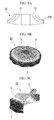
Figs. 10A and 10B , awelded impeller 10 formed in one body by mutually welding constituent members such as acover 1,blades 2, and a disc 3 (showing weld zones with a symbol 4) is known. - Thus, such a
welded impeller 10 is manufactured, as shown inFig. 11 , by independently preparing the cover (shroud) 1, theblades 2, and the disc (hub) 3 (S1), integrally forming these constituent members by weld zones 4 (S2), performing heat treatment such as quenching and tempering for the purpose of removing residual stress after the welding and enhancing hardness and durability (S3), performing finishing using mechanical working and electrical discharge machining (S4), and then performing trimming and polishing using electrolytic polishing and chemical polishing (S5). - In recent years, the impeller has made progress toward high efficiency and high performance, and a shape thereof has necessarily become complicated, diversified, and increased in precision. In the case of the welded impeller, the heat treatment such as quenching and tempering for the purpose of removing residual stress after the welding and enhancing hardness and durability is performed (S3), but during the welding (S2) and the heat treatment (S3), deformation occurs leading to the possibility of dimensional precision being reduced.
- For this reason, for the purpose of reducing the deformation caused by the welding and the heat treatment and improving the dimensional precision, for example, as disclosed in Japanese Unexamined Patent Application, First Publication Nos.
2004-92650 2009-156122 2010-230012 - In the integrated
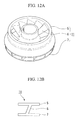
impeller 11 disclosed in these Patent Literatures, as shown inFigs. 12A and 12B , a cover (shroud) 5,blades 6, and a disc (hub) 7, which are main components, are manufactured from a metal serving as a base metal in a predetermined shape by mechanical working and electrical discharge machining, and are free from deformation caused by the welding. For this reason, a precise shape for obtaining desired performance as the impeller can be obtained, and no defects associated with the welding occur. - Thus, the integrated
impeller 11 is manufactured, as shown inFig. 13 , by preparing the cover (shroud) 5, theblades 6, and the disc (hub) 7 from a material made of one block by means of cutting (S6), performing heat treatment for the purpose of hardening a surface and improving toughness (S7), performing finishing using mechanical working and electrical discharge machining (S8), and then performing trimming and polishing using electrolytic polishing and chemical polishing (S9). -
- [Patent Literature 1]
Japanese Unexamined Patent Application, First Publication No.2004-92650 - [Patent Literature 2]
Japanese Unexamined Patent Application, First Publication No.2009-156122 - [Patent Literature 3]
Japanese Unexamined Patent Application, First Publication No.2010-230012 - However, even in the case of the integrated impeller disclosed in
Patent Literatures 1 to 3 above, since the heat treatment such as quenching and temperature for the purpose of enhancing the durability, the deformation occurs during the heat treatment. Such deformation cannot always be predicted in advance. In this respect, there is room for further improvement of the dimensional precision. - To be specific, in the integrated impeller, the process of hardening the surface to improve toughness by performing the heat treatment after the mechanical working is performed. However, in the state of the base metal (metal block) before the mechanical working, as shown in
Fig. 14 , a central portion C located in the center (portion at which a cooling rate is slow) is distant from the surface. As such, a quenching effect is unachievable, and the strength has a tendency to be lowered. During such heat treatment, when a deformation that is not predictable occurs, a process of finishing such as grinding after the heat treatment may be required again to obtain desired dimensional precision. - The present invention has been made in consideration of these circumstances, and an object of the present invention is to provide a method for manufacturing a machine component, capable of predicting strength in the event of heat treatment such as quenching and tempering to thereby reduce an amount of deformation of a base material to optimize a form in the event of the heat treatment, and improving performance of the machine component (impeller) used in a rotary machine, and a rotary machine equipped with an impeller manufactured by this method.
- In order to solve the aforementioned problems, the present invention proposes the following means. According to a first aspect of the present invention, there is provided a method for manufacturing a machine component, in which a base material is subjected to a plurality of mechanical working processes and heat treatment processes and is processed into a final form. The method includes: a process of calculating and estimating post-heat-treatment strength for an intermediate form of the base material after one of the mechanical working processes is performed; and a process of comparing the estimated strength with reference strength required for the final form. According to a result of the comparison, heat treatment is performed after one of the mechanical working processes is performed.
- According to the aspect, the process of estimating the post-heat-treatment strength for the intermediate form of the base material after one of the mechanical working processes is performed, and the process of comparing the estimated strength with the reference strength required for the final form are provided. According to the result of the comparison, the heat treatment of the base material is performed after one of the mechanical working processes is performed. Thereby, when the result of the comparison indicates that the post-heat-treatment strength estimated for the intermediate form of the base material after the mechanical working processes does not meet the reference strength required for the final form, processing of, for instance, changing the form of the base material is performed. Thereby, required strength of the base material can be secured. That is, by reducing an amount of deformation of the base material in the event of the heat treatment to optimize the form in the event of the heat treatment, performance of the machine component (impeller) used in a rotary machine can be improved.
- Further, according to a second aspect of the present invention, in the method for manufacturing the machine component relating to the first aspect of the present invention, finishing (mechanical working or electrical discharge machining) is performed after the heat treatment process.
- According to the aspect, by performing the finishing after the heat treatment process, the base material hardened by quenching can be finished in the final form with a minimum amount of machining.
- Further, according to a third aspect of the present invention, in the method for manufacturing the machine component relating to the first or second aspect of the present invention, the comparing process includes adjusting a thickness of the base material when the estimated strength does not meet the reference strength required for the final form.
- Further, according to a fourth aspect of the present invention, in the method for manufacturing the machine component relating to the third aspect of the present invention, the comparing process includes forming the base material in a cylindrical form, in the center of which an opening is formed, when the estimated strength does not meet the reference strength required for the final form.
- Further, according to a fifth aspect of the present invention, in the method for manufacturing the machine component relating to the fourth aspect of the present invention, the comparing process includes forming a cover profile on an outer surface of the base material formed in the cylindrical form when the estimated strength does not meet the reference strength required for the final form.
- Further, according to a sixth aspect of the present invention, in the method for manufacturing the machine component relating to the fifth aspect of the present invention, the comparing process includes forming flow paths in the base material on which the cover profile is formed when the estimated strength does not meet the reference strength required for the final form.
- According to the aspects, in the comparing process, when the estimated strength does not meet the reference strength required for the final form, various form changing processes of adjusting the thickness of the base material, forming the base material in the cylindrical form, in the center of which the opening is formed, forming the cover profile on the outer surface of the base material of the cylindrical form, and forming the flow paths in the base material on which the blades are formed are performed. Thereby, the required strength of the base material can be reliably secured. That is, by appropriately changing the form of the base material, the form in the event of the heat treatment can be optimized so that hardening of the heat treatment is reliably reached to the central portion of the base material in the event of the heat treatment, and the performance of the machine component (impeller) used in the rotary machine can be improved.
- Further, according to a rotary machine relating to a seventh aspect of the present invention, the rotary machine includes the impeller that is the machine component manufactured by the method relating to any one of the aspects, and a driving shaft that drives the impeller.
- According to the aspect, a high-powered impeller manufactured by the manufacturing method is installed on the rotary machine such as a compressor. Thereby, a quality of the entire rotary machine can be improved.
- According to the aspects, the process of estimating the post-heat-treatment strength for the intermediate form of the base material after a mechanical working process is performed, and the process of comparing the estimated strength with the reference strength required for the final form are provided. According to the result of the comparison, the heat treatment of the base material is performed after a mechanical working process is performed. Thereby, when the result of the comparison indicates that the post-heat-treatment strength estimated for the intermediate form of the base material after the mechanical working processes does not meet the reference strength required for the final form, processing of, for instance, changing the form of the base material is performed. Thereby, the required strength of the base material can be secured. That is, by reducing the amount of deformation of the base material in the event of the heat treatment to optimize the form in the event of the heat treatment, the performance of the machine component (impeller) used in the rotary machine can be improved.
-
-
Fig. 1 is a process diagram schematically showing processes relating to a first embodiment of the present invention. -
Fig. 2 is a flowchart specifically showing the processes (S10 to S13) ofFig. 1 . -
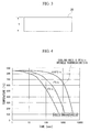
Fig. 3 is a diagram showing a base material having a column form of a thickness (t) used for machining of the first embodiment of the present invention. -
Fig. 4 is a graph showing a continuous cooling transformation curve (CCT curve) showing a relation between cooling temperature, cooling time and hardness of the base material. -
Fig. 5 is a graph showing a tempering performance curve used to determine strength of the base material. -
Fig. 6 is a graph showing a relation between yield strength of a base material central portion, a cooling rate, and a thickness of the base material. -
Fig. 7A is a diagram showing a form of the base material that shows a columnar base material. -
Fig. 7B is a diagram showing a form of the base material that shows a cylindrical base material. -
Fig. 7C is a diagram showing a form of the base material that shows a cylindrical base material in which a cover profile is formed. -
Fig. 8 is a graph showing a relation between yield strength of a base material central portion, a cooling rate, and a thickness of a base material in accordance with a second embodiment of the present invention. -
Fig. 9A is a diagram showing a base material which relates to a third embodiment of the present invention and in which flow paths are formed. -
Fig. 9B is a diagram showing the base material relating to the third embodiment of the present invention and showing results of analyzing a degree of deformation after heat treatment of the base material. -
Fig. 9C is a diagram showing the base material relating to the third embodiment of the present invention and showing the results of analyzing the degree of deformation after the heat treatment of the base material. -
Fig. 10A is an explanatory diagram showing a welded impeller. -
Fig. 10B is an explanatory diagram showing the welded impeller. -
Fig. 11 is a process diagram showing processes of manufacturing the welded impeller. -
Fig. 12A is an explanatory diagram showing an integrated impeller. -
Fig. 12B is an explanatory diagram showing the integrated impeller. -
Fig. 13 is a process diagram showing processes of manufacturing the integrated impeller. -
Fig. 14 is an explanatory diagram showing a central portion of the impeller having poor quenchability. - A first embodiment of the present invention will be described with reference to
Figs. 1 to 6 . -
Fig. 1 is a process diagram schematically showing processes relating to a first embodiment of the present invention that shows timing of heat treatment in the present embodiment.Fig. 2 is a flowchart specifically showing the processes S10 to S 13 ofFig. 1 . - The processes relating to the first embodiment of the present invention are carried out in the sequence shown in
Fig. 1 . First, an impeller material (base material) that has undergone certain mechanical working is prepared (S10). As the present mechanical working, cutting from a block of a solid material is illustrated. Further, as the base material, a metal block having, for example, a short column form or a truncated cone form is illustrated. To provide a prescribed strength to this base material, heat treatment is performed based on conditions estimated by simulation (S11). Afterwards, finishing of forming a cover (shroud), blades, and a disc (hub) from the base material by means of cutting using mechanical working and electrical discharge machining (S12), and trimming and polishing using electrolytic polishing and chemical polishing (S13) are performed. - In the processes relating to the first embodiment of the present invention, to reduce an amount of deformation during heat treatment to improve dimensional precision of a final form, heat treatment such as quenching and tempering is performed without changing a form of the material before flow path machining and profile machining are performed. In other words, prior to cutting forms of the cover, the disc, and the blades, the heat treatment is performed to make required material properties, thereby minimizing an influence which heat treatment deformation exerts on the final form.
- However, as shown in
Fig. 14 , since the base material itself has a thick wall thickness in the event of heat treatment compared to a conventional method, heat treatability of a central portion C may be deteriorated, and a required strength may not be secured. In particular, high hardness and high strength are required at surface-adjacent portions of the cover, the blades, and the disc that form a flow path. However, depending on the form of the base material, the surface-adjacent portions and the central portion C of the base material may overlap. For this reason, first, there is a need to obtain conditions for obtaining prescribed strength after the heat treatment. - Hereinafter, the aforementioned processes S10 to S 13 of
Fig. 1 will be described in detail with reference to the flowchart ofFig. 2 . - First, an impeller material undergoing a certain mechanical working process is prepared. Here, a columnar base material (column material) 20 having a thickness t as shown in
Fig. 3 is assumed. - Next, a calculation is made using
Figs. 4 to 6 on the assumption that heat treatment is performed on thebase material 20. - A thickness of the impeller material is set based on a target form of an impeller, and a cooling rate in the event of quenching is decided by a thickness of the impeller. In general, hardness and strength (yield strength) after the heat treatment are correlated with the cooling rate in the event of quenching. As the cooling rate increases, the hardness and strength of a material become high. The hardness and strength can be predicted using a continuous cooling transformation curve (CCT curve) shown in
Fig. 4 and a tempering performance curve shown inFig. 5 . - For example, in the CCT curve of
Fig. 4 , it is shown that Brinell hardness (HB) when the base material is cooled at 0.25 °C/sec becomes 518. When this is calculated by a difference from a reference line A showing the Brinell hardness (HB) with reference to the tempering curve ofFig. 5 , the Brinell hardness (HB) when tempering is performed at 650 °C is 250. In this case, it can be understood that yield strength (YP) is about 70 kgf/mm2 by a difference from a reference line B. A hardness difference (ΔHB78) from the reference line A of the Brinell hardness (HB) corresponds to a strength difference (Δ26 kgf/mm2) from the reference line B of the yield strength (YP), and a calculation is made based on this. - In the case in which the tempering is performed at 650 °C, the yield strength (YP) of the base material central portion which is obtained in this way is arranged from a relation between the cooling rate (°C/sec) and the thickness t (mm) of the
base material 20, which is shown inFig. 6 . - Then, as can be seen with reference to
Fig. 6 , as the thickness of the base material increases, the cooling rate of the central portion C is reduced. It is found that strength-related data (yield strength, hardness, etc.) achieved accordingly is also reduced. To be specific, when yield strength of 90 kgf/mm2 is sought, the base material thickness t needs to be less than or equal to about 60 mm, and the cooling rate needs to be greater than or equal to 3 °C/sec. Similarly, when yield strength of 80 kgf/mm2 is sought, the base material thickness t needs to be less than or equal to about 120 mm, and the cooling rate needs to be greater than or equal to 1 °C/sec. - In connection with the aforementioned cooling rate in the event of quenching, the cooling rate may be estimated using a method of evaluating the cooling rate with the aid of, for instance, a numerical simulation technique, or a method of directly measuring the cooling rate based on a test.
- Therefore, it is possible to obtain the material thickness corresponding to the required strength and to design the material form in the event of heat treatment using the CCT curve of
Fig. 4 , the tempering curve ofFig. 5 , and the cooling rate ofFig. 6 . A relation between the thickness of the impeller material, the cooling rate and the attained strength may be arranged according to specifications (heating and cooling capabilities) of heat treatment equipment and manufacturing situations. - The aforementioned graphs of
Figs. 4 to 6 are stored in a database and are read out of the database as needed (SP102). - It is determined based on the analysis result in SP101 above whether the
prepared base material 20 having the thickness t in SP100 has a predetermined strength after the heat treatment. In the case of NO, the process proceeds to SP104, and in the case of YES, the process proceeds to SP105. - After the mechanical working of, for instance, changing the thickness t of the
base material 20 is performed based on the analysis result in SP101 (after a change in specification of, for instance, reducing the thickness of thebase material 20 or changing to a thin material according to circumstances is performed), the process returns to SP101, and the strength of the base material after the heat treatment is estimated. - On condition that the strength estimated in SP101 is met, the heat treatment of the
base material 20 is performed. - Mechanical working of, for instance, cutting the
base material 20 heat-treated in SP105 in a given form, and finishing processing are performed. Here, in addition to the typical mechanical working, electrical discharge machining capable of efficiently machining thebase material 20 whose hardness is increased is used. - Trimming and polishing processing of, for instance, performing electrolytic polishing and chemical polishing is performed on the
base material 20 machined in SP106. - As specifically described above, the method for manufacturing the machine component shown in the first embodiment has the
processes SP 100 to SP102 of estimating post-heat-treatment strength for an intermediate form of thebase material 20 after a certain mechanical working process, and the processes SP103 and SP104 of comparing the estimated strength with the required strength for the final form. According to the result of the comparison, the heat treatment of thebase material 20 is performed after one of the aforementioned mechanical working processes (SP105 to SP107). Thereby, when the result of the comparison shows that the estimated post-heat-treatment strength for the intermediate form of thebase material 20 after the mechanical working process does not meet the required strength for the final form, processing of, for instance, changing the form of thebase material 20 is performed (SP104). Thereby, the required strength of thebase material 20 can be secured. In other words, by reducing an amount of deformation of thebase material 20 in the event of the heat treatment to optimize the form in the event of the heat treatment, it is possible to improve the performance of the machine component (impeller) used in the rotary machine. - Further, in the method for manufacturing the machine component shown in the first embodiment, the electrical discharge machining is performed after the heat treatment process (SP105), and thereby even the
base material 20 whose strength is increased can be easily machined. - A second embodiment of the present invention will be described with reference to
Figs. 7A to 8 . - In the aforementioned first embodiment, the mechanical working of, for instance, changing the thickness t of the
base material 20 based on the analysis result of SP101 is performed in SP104. In the second embodiment, in addition to the thickness t of thebase material 20, appropriate rough processing is performed depending on the thickness of thebase material 20, and the overall form of thebase material 20 is changed. Thereby, the heat treatment form is optimized. - To be specific, an initial form of the
base material 20 is, as shown inFig. 7A , a columnar block form (column material denoted by asymbol 20A). When it is estimated by this form that the post-heat-treatment strength is insufficient, for example, rough processing (shaft hole drilling) is performed as pre-heat-treatment machining, as shown inFig. 7B , so as to become a cylindrical shape (denoted by asymbol 20B) in which a shaft hole is formed in the center of the impeller material. Further, when it is estimated by this cylindrical shape (denoted by thesymbol 20B) that the post-heat-treatment strength is insufficient, rough processing (profile machining) is performed, as shown inFig. 7C , in a cylindrical shape (denoted by asymbol 20C) obtained by forming a cover profile on an outer surface of thebase material 20 in the center of which an opening is formed. Thereby, the cooling rate in the event of the heat treatment is increased, and the strength of thebase material 20 is improved. - Further, one of the
form 20A to 20C in which thebase material 20 is formed in SP104 is decided from the graph showing a relation between the cooling rate and the material thickness of each of theforms 20A to 20C shown inFig. 8 . - For example, depending on the required
strengths forms 20A to 20C are selected, and the material thickness corresponding to the set cooling rate (3 °C/sec in the present embodiment) is decided from "the graph showing the relation between the cooling rate and the material thickness of each of theforms 20A to 20C" corresponding to the selected form. - In detail, when the cooling rate is set to 3 °C/sec, the material thickness that can only be about 60 mm in the
form 20A can be selected up to about 85 mm if theform 20B is set, and up to 120 mm if theform 20C is set. - In this way, in the second embodiment, the processing of changing to one of the
forms 20A to 20C depending on the requiredstrengths base material 20 actually meets the strength in SP101. - As described above in detail, in the method for manufacturing the machine component shown in the second embodiment, in SP104, in addition to performing the mechanical working of, for instance, changing the thickness t of the
base material 20 based on the analysis result of SP101, by performing the appropriate rough processing depending on the thickness of thebase material 20 and changing the overall form of the base material 20 (for example, from theform 20A to theform 20B, and furthermore to theform 20C), the heat treatment form is optimized. That is, in the second embodiment, when the thickness of theimpeller material 20 is relatively thick, the relation between the material thickness in the event of the rough-processing form, the cooling rate and the attained strength are previously arranged. Thereby, the optimal form is selected, and the heat treatment in which an amount of deformation is reduced as in the first embodiment can be performed. - A third embodiment of the present invention will be described with reference to
Figs. 9A to 9C . - In the aforementioned second embodiment, in SP104, by performing the appropriate rough processing depending on the thickness of the
base material 20 and changing the overall form of the base material 20 (from theform 20A to theforms Fig. 9A , mechanical working (flow path machining) for formingflow paths 21 may be adapted to be performed on the base material 20 (this is defined as aform 20D). - Then, even in the case of this
form 20D shown inFig. 9A (heat treatment form), similar to the second embodiment, the required strength in the event of the heat treatment is calculated from analysis results (deformation analysis result example) showing a degree of deformation of thebase material 20 shown inFigs. 9B and 9C after the heat treatment. Further, in this case, the required strength in the event of the heat treatment is calculated in consideration of a relation between the cooling rate and the material thickness of theform 20D as well as a proper wall thickness of the material between the flow paths. - Then, processing of changing a thickness of each blade portion of the
form 20D depending on the requiredstrengths base material 20 actually meets the strength in SP101. - As described above in detail, in the method for manufacturing the machine component shown in the third embodiment, in SP104, in addition to performing the mechanical working of, for instance, changing the thickness t of the
base material 20 based on the analysis result of SP101, by performing the appropriate rough processing depending on the thickness of each portion of thebase material 20 and changing the overall form of the base material 20 (from theform 20A to theforms form 20D in which theflow paths 21 are formed in the outer surface of theform 20C serving as thebase material 20, the heat treatment form is optimized. That is, in the third embodiment, the processing of changing the overall form of the base material 20 (from theform 20A to theforms form 20D in which theflow paths 21 are formed in the outer surface of thebase material 20 is performed. Thereby, the heat treatment in which an amount of deformation is minimized as in the second embodiment can be performed. - The prediction of the strength of the
base material 20 after the heat treatment using the graphs shown inFigs. 4 to 6 and8 is one example. If the form of the base material to be evaluated is different, the graphs are different, and the graphs are appropriately replaced depending to the target to be evaluated. - While embodiments of the present invention have been described with reference to the drawings, the specific constitution is not limited to these embodiments and also includes design modification without departing from the gist of the present invention.
- According to the description above, it is determined based on simulation whether or not strength-related data (yield strength, hardness, etc.) predicted from the thickness of a base material such as an impeller material (machine component) meets required specifications, and heat treatment is performed based on results of the determination. Thus, it is possible to minimize deformation of the base material in the event of the heat treatment.
-
- 20A to 20D
- base material (machine component)
Claims (7)
- A method for manufacturing a machine component, in which a base material is subjected to a plurality of mechanical working processes and heat treatment processes and is processed into a final form, the method comprising:a process of calculating and estimating post-heat-treatment strength for an intermediate form of the base material after one of the mechanical working processes is performed; anda process of comparing the estimated strength with reference strength required for the final form,wherein, based on a result of the comparison, heat treatment is performed after the one of the mechanical working processes is performed.
- The method for manufacturing the machine component according to claim 1, wherein finishing is performed after the heat treatment process.
- The method for manufacturing the machine component according to claim 1 or 2, wherein the comparing process includes adjusting a thickness of the base material when the estimated strength does not meet the reference strength required for the final form.
- The method for manufacturing the machine component according to claim 3, wherein the comparing process includes making the base material in a cylindrical form, in the center of which an opening is formed, when the estimated strength does not meet the reference strength required for the final form.
- The method for manufacturing the machine component according to claim 4, wherein the comparing process includes forming a cover profile on an outer surface of the base material formed in the cylindrical form when the estimated strength does not meet the reference strength required for the final form.
- The method for manufacturing the machine component according to claim 5, wherein the comparing process includes forming flow paths in the base material on which the cover profile is formed when the estimated strength does not meet the reference strength required for the final form.
- A rotary machine equipped with an impeller, comprising the impeller that is the machine component manufactured by the method according to one of claims 1 to 6, and a driving shaft that drives the impeller.
Applications Claiming Priority (2)
| Application Number | Priority Date | Filing Date | Title |
|---|---|---|---|
| JP2011281606A JP5738169B2 (en) | 2011-12-22 | 2011-12-22 | MANUFACTURING METHOD FOR MECHANICAL PARTS AND ROTARY MACHINE HAVING IMPER |
| PCT/JP2012/083016 WO2013094670A1 (en) | 2011-12-22 | 2012-12-20 | Method for manufacturing machine component, and rotary machine equipped with impeller manufactured by means of this method |
Publications (3)
| Publication Number | Publication Date |
|---|---|
| EP2749772A1 true EP2749772A1 (en) | 2014-07-02 |
| EP2749772A4 EP2749772A4 (en) | 2015-05-20 |
| EP2749772B1 EP2749772B1 (en) | 2017-08-23 |
Family
ID=48668553
Family Applications (1)
| Application Number | Title | Priority Date | Filing Date |
|---|---|---|---|
| EP12859468.6A Not-in-force EP2749772B1 (en) | 2011-12-22 | 2012-12-20 | Method for manufacturing machine component |
Country Status (5)
| Country | Link |
|---|---|
| US (1) | US9644482B2 (en) |
| EP (1) | EP2749772B1 (en) |
| JP (1) | JP5738169B2 (en) |
| CN (1) | CN103518068B (en) |
| WO (1) | WO2013094670A1 (en) |
Cited By (1)
| Publication number | Priority date | Publication date | Assignee | Title |
|---|---|---|---|---|
| CN105583593A (en) * | 2016-02-25 | 2016-05-18 | 成都亨通兆业精密机械有限公司 | High-speed machining technology for automobile die |
Families Citing this family (2)
| Publication number | Priority date | Publication date | Assignee | Title |
|---|---|---|---|---|
| US10378509B2 (en) * | 2017-10-06 | 2019-08-13 | Iap, Inc. | Turbine rotor for redirecting fluid flow including sinuously shaped blades and a solid conical center core |
| CN113609739B (en) * | 2021-08-17 | 2023-09-26 | 中南大学 | Construction method of material heat treatment process and microstructure and performance relation database |
Family Cites Families (12)
| Publication number | Priority date | Publication date | Assignee | Title |
|---|---|---|---|---|
| CA1155712A (en) * | 1979-10-29 | 1983-10-25 | Rockwell International Corporation | Composite centrifugal impeller for slurry pumps |
| US5438755A (en) * | 1993-11-17 | 1995-08-08 | Giberson; Melbourne F. | Method of making a monolithic shrouded impeller |
| US5593085A (en) * | 1995-03-22 | 1997-01-14 | Solar Turbines Incorporated | Method of manufacturing an impeller assembly |
| WO2003048405A1 (en) * | 2001-11-30 | 2003-06-12 | Koyo Thermo Systems Co., Ltd. | Method and apparatus for vacuum heat treatment |
| ITMI20021876A1 (en) * | 2002-09-03 | 2004-03-04 | Nuovo Pignone Spa | IMPROVED PROCEDURE FOR MAKING A ROTOR OF ONE |
| US7370787B2 (en) | 2003-12-15 | 2008-05-13 | Pratt & Whitney Canada Corp. | Compressor rotor and method for making |
| US7273352B2 (en) * | 2004-01-09 | 2007-09-25 | United Technologies Corporation | Inlet partial blades for structural integrity and performance |
| US7628586B2 (en) * | 2005-12-28 | 2009-12-08 | Elliott Company | Impeller |
| US20090092494A1 (en) * | 2007-10-04 | 2009-04-09 | General Electric Company | Disk rotor and method of manufacture |
| JP2009156122A (en) | 2007-12-26 | 2009-07-16 | Mitsubishi Heavy Ind Ltd | Impeller for centrifugal compressor |
| JP5653653B2 (en) * | 2010-05-13 | 2015-01-14 | 三菱重工業株式会社 | Method for manufacturing material for rotating machine part, method for manufacturing rotating machine part, material for rotating machine part, rotating machine part and centrifugal compressor |
| JP5422482B2 (en) * | 2010-05-17 | 2014-02-19 | 三菱重工業株式会社 | Impeller manufacturing method |
-
2011
- 2011-12-22 JP JP2011281606A patent/JP5738169B2/en not_active Expired - Fee Related
-
2012
- 2012-12-20 WO PCT/JP2012/083016 patent/WO2013094670A1/en not_active Ceased
- 2012-12-20 US US14/123,269 patent/US9644482B2/en not_active Expired - Fee Related
- 2012-12-20 CN CN201280019908.6A patent/CN103518068B/en not_active Expired - Fee Related
- 2012-12-20 EP EP12859468.6A patent/EP2749772B1/en not_active Not-in-force
Cited By (1)
| Publication number | Priority date | Publication date | Assignee | Title |
|---|---|---|---|---|
| CN105583593A (en) * | 2016-02-25 | 2016-05-18 | 成都亨通兆业精密机械有限公司 | High-speed machining technology for automobile die |
Also Published As
| Publication number | Publication date |
|---|---|
| EP2749772A4 (en) | 2015-05-20 |
| JP2013130165A (en) | 2013-07-04 |
| EP2749772B1 (en) | 2017-08-23 |
| CN103518068A (en) | 2014-01-15 |
| WO2013094670A1 (en) | 2013-06-27 |
| JP5738169B2 (en) | 2015-06-17 |
| US9644482B2 (en) | 2017-05-09 |
| CN103518068B (en) | 2016-08-17 |
| US20140105751A1 (en) | 2014-04-17 |
Similar Documents
| Publication | Publication Date | Title |
|---|---|---|
| EP2749772B1 (en) | Method for manufacturing machine component | |
| US9994944B2 (en) | Steel for cold forging/nitriding, steel material for cold forging/nitriding, and cold-forged/nitrided component | |
| CN104451086B (en) | The manufacture method of steamturbine rotor | |
| KR101718871B1 (en) | Method for producing plastic moulds out of martensitic chrome steel and plastic mould | |
| US10626487B2 (en) | Austenitic heat-resistant cast steel and method for manufacturing the same | |
| EP3342892A1 (en) | Mechanical structure steel for cold-working and manufacturing method therefor | |
| KR101290457B1 (en) | Martensitic-steel casting material and process for producing martensitic cast steel product | |
| JP2010159486A (en) | Soft-nitriding crankshaft member and steel for soft-nitriding crankshaft | |
| WO2013150844A1 (en) | Steel for cold forging/nitriding, steel material for cold forging/nitriding, and cold forged/nitrided member | |
| WO2014181882A1 (en) | Surface grain refining hot-shearing method and product of surface grain refining hot-shearing | |
| JP5713195B2 (en) | Pre-hardened steel for plastic molds | |
| EP2570504B1 (en) | Method for manufacturing raw material for rotary machine component, method for manufacturing rotary machine component, rotary machine component and centrifugal compressor | |
| EP3214189B1 (en) | Method for manufacturing a quenched and tempered seamless pipe for a high-strength hollow spring | |
| EP3272896A1 (en) | Age-hardenable steel, and method for manufacturing components using age-hardenable steel | |
| JP5825152B2 (en) | Cold forging and nitriding steel and cold forging and nitriding parts | |
| EP4524267A1 (en) | Mechanical structural member and production method for same | |
| CN106574504B (en) | Shaft manufacturing method | |
| US20040108027A1 (en) | Method of making a hardened steel part, especially a roll load-bearing steel part | |
| Goldstein et al. | Virtual Prototyping of Induction Heat Treating | |
| CN101460639B (en) | Process for applying internal compressive stresses in a shaft, in particular in shaft notches | |
| EP4411004A1 (en) | Selective heat treatment of metals using a coil-in-furnace system | |
| JP7343767B2 (en) | Crankshaft and its manufacturing method | |
| Lof et al. | Flap-X: Development of a new compressor reed material | |
| JP2006297429A (en) | Mold damage prediction method | |
| CN106591546A (en) | Rapid inspection method for bearing steel spheroidizing annealing material carbon scarcity and decarburization |
Legal Events
| Date | Code | Title | Description |
|---|---|---|---|
| PUAI | Public reference made under article 153(3) epc to a published international application that has entered the european phase |
Free format text: ORIGINAL CODE: 0009012 |
|
| 17P | Request for examination filed |
Effective date: 20131126 |
|
| AK | Designated contracting states |
Kind code of ref document: A1 Designated state(s): AL AT BE BG CH CY CZ DE DK EE ES FI FR GB GR HR HU IE IS IT LI LT LU LV MC MK MT NL NO PL PT RO RS SE SI SK SM TR |
|
| DAX | Request for extension of the european patent (deleted) | ||
| REG | Reference to a national code |
Ref country code: DE Ref legal event code: R079 Ref document number: 602012036452 Country of ref document: DE Free format text: PREVIOUS MAIN CLASS: F04D0029280000 Ipc: C21D0011000000 |
|
| RA4 | Supplementary search report drawn up and despatched (corrected) |
Effective date: 20150420 |
|
| RIC1 | Information provided on ipc code assigned before grant |
Ipc: C21D 11/00 20060101AFI20150414BHEP Ipc: C21D 1/30 20060101ALI20150414BHEP Ipc: B23P 15/00 20060101ALI20150414BHEP Ipc: F04D 29/28 20060101ALI20150414BHEP |
|
| GRAP | Despatch of communication of intention to grant a patent |
Free format text: ORIGINAL CODE: EPIDOSNIGR1 |
|
| INTG | Intention to grant announced |
Effective date: 20170509 |
|
| RIN1 | Information on inventor provided before grant (corrected) |
Inventor name: KITAMOTO, HIROKO Inventor name: OKAYASU, SHIMPEI Inventor name: TAKAGI, HIROKI Inventor name: YAGI, NOBUYORI Inventor name: KAWANISHI, DAISUKE |
|
| RAP1 | Party data changed (applicant data changed or rights of an application transferred) |
Owner name: MITSUBISHI HEAVY INDUSTRIES COMPRESSOR CORPORATION |
|
| GRAS | Grant fee paid |
Free format text: ORIGINAL CODE: EPIDOSNIGR3 |
|
| GRAA | (expected) grant |
Free format text: ORIGINAL CODE: 0009210 |
|
| AK | Designated contracting states |
Kind code of ref document: B1 Designated state(s): AL AT BE BG CH CY CZ DE DK EE ES FI FR GB GR HR HU IE IS IT LI LT LU LV MC MK MT NL NO PL PT RO RS SE SI SK SM TR |
|
| REG | Reference to a national code |
Ref country code: GB Ref legal event code: FG4D |
|
| REG | Reference to a national code |
Ref country code: CH Ref legal event code: EP |
|
| REG | Reference to a national code |
Ref country code: AT Ref legal event code: REF Ref document number: 921418 Country of ref document: AT Kind code of ref document: T Effective date: 20170915 |
|
| REG | Reference to a national code |
Ref country code: IE Ref legal event code: FG4D |
|
| REG | Reference to a national code |
Ref country code: DE Ref legal event code: R096 Ref document number: 602012036452 Country of ref document: DE |
|
| REG | Reference to a national code |
Ref country code: NL Ref legal event code: MP Effective date: 20170823 |
|
| REG | Reference to a national code |
Ref country code: LT Ref legal event code: MG4D |
|
| REG | Reference to a national code |
Ref country code: AT Ref legal event code: MK05 Ref document number: 921418 Country of ref document: AT Kind code of ref document: T Effective date: 20170823 |
|
| PG25 | Lapsed in a contracting state [announced via postgrant information from national office to epo] |
Ref country code: NL Free format text: LAPSE BECAUSE OF FAILURE TO SUBMIT A TRANSLATION OF THE DESCRIPTION OR TO PAY THE FEE WITHIN THE PRESCRIBED TIME-LIMIT Effective date: 20170823 Ref country code: FI Free format text: LAPSE BECAUSE OF FAILURE TO SUBMIT A TRANSLATION OF THE DESCRIPTION OR TO PAY THE FEE WITHIN THE PRESCRIBED TIME-LIMIT Effective date: 20170823 Ref country code: SE Free format text: LAPSE BECAUSE OF FAILURE TO SUBMIT A TRANSLATION OF THE DESCRIPTION OR TO PAY THE FEE WITHIN THE PRESCRIBED TIME-LIMIT Effective date: 20170823 Ref country code: NO Free format text: LAPSE BECAUSE OF FAILURE TO SUBMIT A TRANSLATION OF THE DESCRIPTION OR TO PAY THE FEE WITHIN THE PRESCRIBED TIME-LIMIT Effective date: 20171123 Ref country code: LT Free format text: LAPSE BECAUSE OF FAILURE TO SUBMIT A TRANSLATION OF THE DESCRIPTION OR TO PAY THE FEE WITHIN THE PRESCRIBED TIME-LIMIT Effective date: 20170823 Ref country code: HR Free format text: LAPSE BECAUSE OF FAILURE TO SUBMIT A TRANSLATION OF THE DESCRIPTION OR TO PAY THE FEE WITHIN THE PRESCRIBED TIME-LIMIT Effective date: 20170823 Ref country code: AT Free format text: LAPSE BECAUSE OF FAILURE TO SUBMIT A TRANSLATION OF THE DESCRIPTION OR TO PAY THE FEE WITHIN THE PRESCRIBED TIME-LIMIT Effective date: 20170823 |
|
| PG25 | Lapsed in a contracting state [announced via postgrant information from national office to epo] |
Ref country code: PL Free format text: LAPSE BECAUSE OF FAILURE TO SUBMIT A TRANSLATION OF THE DESCRIPTION OR TO PAY THE FEE WITHIN THE PRESCRIBED TIME-LIMIT Effective date: 20170823 Ref country code: RS Free format text: LAPSE BECAUSE OF FAILURE TO SUBMIT A TRANSLATION OF THE DESCRIPTION OR TO PAY THE FEE WITHIN THE PRESCRIBED TIME-LIMIT Effective date: 20170823 Ref country code: ES Free format text: LAPSE BECAUSE OF FAILURE TO SUBMIT A TRANSLATION OF THE DESCRIPTION OR TO PAY THE FEE WITHIN THE PRESCRIBED TIME-LIMIT Effective date: 20170823 Ref country code: LV Free format text: LAPSE BECAUSE OF FAILURE TO SUBMIT A TRANSLATION OF THE DESCRIPTION OR TO PAY THE FEE WITHIN THE PRESCRIBED TIME-LIMIT Effective date: 20170823 Ref country code: GR Free format text: LAPSE BECAUSE OF FAILURE TO SUBMIT A TRANSLATION OF THE DESCRIPTION OR TO PAY THE FEE WITHIN THE PRESCRIBED TIME-LIMIT Effective date: 20171124 Ref country code: IS Free format text: LAPSE BECAUSE OF FAILURE TO SUBMIT A TRANSLATION OF THE DESCRIPTION OR TO PAY THE FEE WITHIN THE PRESCRIBED TIME-LIMIT Effective date: 20171223 Ref country code: BG Free format text: LAPSE BECAUSE OF FAILURE TO SUBMIT A TRANSLATION OF THE DESCRIPTION OR TO PAY THE FEE WITHIN THE PRESCRIBED TIME-LIMIT Effective date: 20171123 |
|
| PG25 | Lapsed in a contracting state [announced via postgrant information from national office to epo] |
Ref country code: DK Free format text: LAPSE BECAUSE OF FAILURE TO SUBMIT A TRANSLATION OF THE DESCRIPTION OR TO PAY THE FEE WITHIN THE PRESCRIBED TIME-LIMIT Effective date: 20170823 Ref country code: CZ Free format text: LAPSE BECAUSE OF FAILURE TO SUBMIT A TRANSLATION OF THE DESCRIPTION OR TO PAY THE FEE WITHIN THE PRESCRIBED TIME-LIMIT Effective date: 20170823 Ref country code: RO Free format text: LAPSE BECAUSE OF FAILURE TO SUBMIT A TRANSLATION OF THE DESCRIPTION OR TO PAY THE FEE WITHIN THE PRESCRIBED TIME-LIMIT Effective date: 20170823 |
|
| REG | Reference to a national code |
Ref country code: DE Ref legal event code: R097 Ref document number: 602012036452 Country of ref document: DE |
|
| PG25 | Lapsed in a contracting state [announced via postgrant information from national office to epo] |
Ref country code: SM Free format text: LAPSE BECAUSE OF FAILURE TO SUBMIT A TRANSLATION OF THE DESCRIPTION OR TO PAY THE FEE WITHIN THE PRESCRIBED TIME-LIMIT Effective date: 20170823 Ref country code: SK Free format text: LAPSE BECAUSE OF FAILURE TO SUBMIT A TRANSLATION OF THE DESCRIPTION OR TO PAY THE FEE WITHIN THE PRESCRIBED TIME-LIMIT Effective date: 20170823 Ref country code: EE Free format text: LAPSE BECAUSE OF FAILURE TO SUBMIT A TRANSLATION OF THE DESCRIPTION OR TO PAY THE FEE WITHIN THE PRESCRIBED TIME-LIMIT Effective date: 20170823 |
|
| PLBE | No opposition filed within time limit |
Free format text: ORIGINAL CODE: 0009261 |
|
| STAA | Information on the status of an ep patent application or granted ep patent |
Free format text: STATUS: NO OPPOSITION FILED WITHIN TIME LIMIT |
|
| REG | Reference to a national code |
Ref country code: CH Ref legal event code: PL |
|
| 26N | No opposition filed |
Effective date: 20180524 |
|
| GBPC | Gb: european patent ceased through non-payment of renewal fee |
Effective date: 20171220 |
|
| PG25 | Lapsed in a contracting state [announced via postgrant information from national office to epo] |
Ref country code: SI Free format text: LAPSE BECAUSE OF FAILURE TO SUBMIT A TRANSLATION OF THE DESCRIPTION OR TO PAY THE FEE WITHIN THE PRESCRIBED TIME-LIMIT Effective date: 20170823 |
|
| REG | Reference to a national code |
Ref country code: IE Ref legal event code: MM4A |
|
| PG25 | Lapsed in a contracting state [announced via postgrant information from national office to epo] |
Ref country code: MT Free format text: LAPSE BECAUSE OF NON-PAYMENT OF DUE FEES Effective date: 20171220 Ref country code: LU Free format text: LAPSE BECAUSE OF NON-PAYMENT OF DUE FEES Effective date: 20171220 |
|
| REG | Reference to a national code |
Ref country code: FR Ref legal event code: ST Effective date: 20180831 |
|
| REG | Reference to a national code |
Ref country code: BE Ref legal event code: MM Effective date: 20171231 |
|
| PG25 | Lapsed in a contracting state [announced via postgrant information from national office to epo] |
Ref country code: FR Free format text: LAPSE BECAUSE OF NON-PAYMENT OF DUE FEES Effective date: 20180102 Ref country code: IE Free format text: LAPSE BECAUSE OF NON-PAYMENT OF DUE FEES Effective date: 20171220 |
|
| PG25 | Lapsed in a contracting state [announced via postgrant information from national office to epo] |
Ref country code: LI Free format text: LAPSE BECAUSE OF NON-PAYMENT OF DUE FEES Effective date: 20171231 Ref country code: BE Free format text: LAPSE BECAUSE OF NON-PAYMENT OF DUE FEES Effective date: 20171231 Ref country code: GB Free format text: LAPSE BECAUSE OF NON-PAYMENT OF DUE FEES Effective date: 20171220 Ref country code: CH Free format text: LAPSE BECAUSE OF NON-PAYMENT OF DUE FEES Effective date: 20171231 |
|
| PG25 | Lapsed in a contracting state [announced via postgrant information from national office to epo] |
Ref country code: HU Free format text: LAPSE BECAUSE OF FAILURE TO SUBMIT A TRANSLATION OF THE DESCRIPTION OR TO PAY THE FEE WITHIN THE PRESCRIBED TIME-LIMIT; INVALID AB INITIO Effective date: 20121220 Ref country code: MC Free format text: LAPSE BECAUSE OF FAILURE TO SUBMIT A TRANSLATION OF THE DESCRIPTION OR TO PAY THE FEE WITHIN THE PRESCRIBED TIME-LIMIT Effective date: 20170823 |
|
| PG25 | Lapsed in a contracting state [announced via postgrant information from national office to epo] |
Ref country code: CY Free format text: LAPSE BECAUSE OF NON-PAYMENT OF DUE FEES Effective date: 20170823 |
|
| PG25 | Lapsed in a contracting state [announced via postgrant information from national office to epo] |
Ref country code: MK Free format text: LAPSE BECAUSE OF FAILURE TO SUBMIT A TRANSLATION OF THE DESCRIPTION OR TO PAY THE FEE WITHIN THE PRESCRIBED TIME-LIMIT Effective date: 20170823 |
|
| PG25 | Lapsed in a contracting state [announced via postgrant information from national office to epo] |
Ref country code: TR Free format text: LAPSE BECAUSE OF FAILURE TO SUBMIT A TRANSLATION OF THE DESCRIPTION OR TO PAY THE FEE WITHIN THE PRESCRIBED TIME-LIMIT Effective date: 20170823 |
|
| PG25 | Lapsed in a contracting state [announced via postgrant information from national office to epo] |
Ref country code: PT Free format text: LAPSE BECAUSE OF FAILURE TO SUBMIT A TRANSLATION OF THE DESCRIPTION OR TO PAY THE FEE WITHIN THE PRESCRIBED TIME-LIMIT Effective date: 20170823 |
|
| PG25 | Lapsed in a contracting state [announced via postgrant information from national office to epo] |
Ref country code: AL Free format text: LAPSE BECAUSE OF FAILURE TO SUBMIT A TRANSLATION OF THE DESCRIPTION OR TO PAY THE FEE WITHIN THE PRESCRIBED TIME-LIMIT Effective date: 20170823 |
|
| PGFP | Annual fee paid to national office [announced via postgrant information from national office to epo] |
Ref country code: IT Payment date: 20231110 Year of fee payment: 12 Ref country code: DE Payment date: 20231031 Year of fee payment: 12 |
|
| REG | Reference to a national code |
Ref country code: DE Ref legal event code: R119 Ref document number: 602012036452 Country of ref document: DE |
|
| PG25 | Lapsed in a contracting state [announced via postgrant information from national office to epo] |
Ref country code: DE Free format text: LAPSE BECAUSE OF NON-PAYMENT OF DUE FEES Effective date: 20250701 |
|
| PG25 | Lapsed in a contracting state [announced via postgrant information from national office to epo] |
Ref country code: IT Free format text: LAPSE BECAUSE OF NON-PAYMENT OF DUE FEES Effective date: 20241220 |