EP2749769A1 - Radial piston hydraulic machine and wind turbine generator - Google Patents
Radial piston hydraulic machine and wind turbine generator Download PDFInfo
- Publication number
- EP2749769A1 EP2749769A1 EP13199744.7A EP13199744A EP2749769A1 EP 2749769 A1 EP2749769 A1 EP 2749769A1 EP 13199744 A EP13199744 A EP 13199744A EP 2749769 A1 EP2749769 A1 EP 2749769A1
- Authority
- EP
- European Patent Office
- Prior art keywords
- hydraulic
- pressure
- low
- cylinder block
- oil
- Prior art date
- Legal status (The legal status is an assumption and is not a legal conclusion. Google has not performed a legal analysis and makes no representation as to the accuracy of the status listed.)
- Granted
Links
Images









Classifications
-
- F—MECHANICAL ENGINEERING; LIGHTING; HEATING; WEAPONS; BLASTING
- F04—POSITIVE - DISPLACEMENT MACHINES FOR LIQUIDS; PUMPS FOR LIQUIDS OR ELASTIC FLUIDS
- F04B—POSITIVE-DISPLACEMENT MACHINES FOR LIQUIDS; PUMPS
- F04B1/00—Multi-cylinder machines or pumps characterised by number or arrangement of cylinders
- F04B1/04—Multi-cylinder machines or pumps characterised by number or arrangement of cylinders having cylinders in star- or fan-arrangement
- F04B1/047—Multi-cylinder machines or pumps characterised by number or arrangement of cylinders having cylinders in star- or fan-arrangement with actuating or actuated elements at the outer ends of the cylinders
- F04B1/0472—Multi-cylinder machines or pumps characterised by number or arrangement of cylinders having cylinders in star- or fan-arrangement with actuating or actuated elements at the outer ends of the cylinders with cam-actuated distribution members
Definitions
- the present disclosure relates to a radial piston hydraulic machine and a wind turbine generator equipped with the same.
- a radial piston hydraulic machine having a plurality of pistons arranged radially has been known.
- a radial piston hydraulic pump using a power transmission device is disclosed in Patent Document 1.
- This hydraulic pump is provided with an outer race having a cam face on an inner peripheral surface and an inner race having a plurality of cylinders arranged radially to face the outer race.
- the plurality of cylinders of the inner race is configured to guide a plurality of pistons, respectively.
- Each of the pistons has a ball contacting the cam face.
- Patent Document 2 discloses a radial piston hydraulic machine which serves as a drive train for a wind turbine generator.
- the radial piston hydraulic machine described in Patent Document 2 is provided with a piston which is reciprocable in a cylinder, a roller attached to the piston and a cam having a cam face contacting the roller.
- An object of at least one embodiment of the present invention is to provide a radial piston hydraulic machine and a wind turbine generator, where maintenance is facilitated.
- the cartridge forms a slide part with respect to high pressure valve and the low pressure valve.
- the cartridge and/or the low pressure valve and the high pressure valve need to be replaced, and the cylinder block body does not basically need to be replaced.
- the cartridge When replacing the cartridge, the cartridge is simply removed from and inserted into the cartridge hole of the cylinder block body in the radial direction and thus, it is easy to replace the cartridge.
- the cartridge is configured to be removable from and insertable into the plurality of cartridge holes together with the low pressure valve and the high pressure valve, the low pressure valve and the high pressure valve can be removed together with the cartridge from the cartridge hole at the maintenance of the low pressure valve and the high pressure valve.
- it is easy to perform maintenance such as replacement of the low pressure valve and the high pressure valve.
- this radial piston hydraulic machine is easy to maintain.
- the plurality of cartridges includes a plurality of cylinder sleeves which forms the plurality of cylinders, respectively, the plurality of cylinder sleeves includes a plurality of end-stops, respectively, for restricting the plurality of pistons from coming out from the plurality of cylinder sleeves, respectively, and the plurality of pistons is engageable with the plurality of cylinder sleeves by means of the plurality of end-stops, and the plurality of cartridges is configured to be removable from and insertable into the plurality of cartridge holes of the cylinder block body together with the plurality of pistons along the radial directions, respectively.
- the cylinder sleeve which is a part of the cartridge forms the slide part with respect to the piston.
- the cylinder block body need not be replaced, replacing of the cylinder sleeve and/or the piston in the above described manner is sufficient.
- the cartridge is removed from and inserted into the cartridge hole of the cylinder block body in the radial direction. This facilitates the replacement work of the cartridge.
- the cartridge is configured removable and insertable together with the piston with respect to the cartridge hole and this facilitates the replacement work of the piston.
- the piston is engageable with the cylinder sleeve by means of the end-stop and thus, it is possible to restrict the piston from coming out from the cylinder sleeve. Therefore, during the replacement work of the cylinder sleeve or the piston, the piston is prevented from coming out from the cylinder sleeve and this facilitates the replacement work.
- the radial piston hydraulic machine further comprises:
- the plurality of cartridges can be removed from and inserted into the plurality of cartridge holes together with the plurality of pistons and the plurality of rollers by using a space on the opposite side of the cylinder block from the ring cam.
- the plurality of rollers is engageable with the plurality of pistons so as to restrict the plurality of rollers from coming out from the plurality of pistons in an axial direction of the plurality of pistons, respectively.
- the plurality of cartridge holes has a size greater than the roller from the plurality of rollers.
- the roller can be removed from the cylinder block body through the cartridge hole. For instance, when removing or inserting the cartridge together with the piston and the roller with respect to the cartridge hole, the roller and the cartridge hole are prevented from interfering with each other. Thus, it is possible to smoothly perform insertion or removal of an assembly of the cartridge with the roller and the piston with respect to the cartridge hole.
- each of the plurality of cartridge holes includes: a first portion having a circular cross sectional shape and provided in a first region corresponding to each of a plurality of hydraulic chambers formed, respectively, by the plurality of pistons and the plurality of cylinders; and a second portion provided nearer to each of the plurality of rollers than the first region and having a cross sectional shape where at least a notched portion corresponding to each end of each of the plurality of rollers is added to a circular cross-section whose diameter is less than a diagonal length of each of the plurality of rollers.
- the cross section of the second portion of the cartridge hole is smaller than the cross section of the first portion, and a thickness of a section of the cylinder block body surrounding the second portion is formed thick. As a result, the strength of the cylinder block body can be improved.
- the plurality of cartridges includes the plurality of cylinder sleeves which forms the plurality of cylinders, respectively.
- each of the plurality of cylinder sleeves includes a first sleeve portion and a second sleeve portion.
- the fist sleeve portion and the second sleeve portion of each of the plurality of cylinder sleeves, respectively, correspond to the first portion and the second portion of each of the plurality of the cartridge holes.
- a stepped portion is provided between the first sleeve portion and the second sleeve portion.
- the cylinder sleeve can be positioned in the cartridge hole using the stepped portion of the cylinder sleeve. Further, corresponding to the stepped portion, a thickness of the first sleeve portion can be made greater than that of the second sleeve portion. As a result, the cylinder sleeve can possess high strength.
- each of the plurality of cartridges includes a valve block retaining each of the plurality of low-pressure valves and each of the high-pressure valves.
- valve block including the low pressure valve and the high pressure valve is incorporated in the valve block.
- the low pressure valve and the high pressure valve are not arranged between adjacent two of the cartridges, it is no longer necessary to separately provide a valve installation space for the low pressure valve and the high pressure valve in the cylinder block body. Therefore, it is possible to achieve improved installation density of the cartridges in the cylinder block.
- each of the plurality of low-pressure valves and each of the plurality of high-pressure valves are aligned along the axis direction of the cartridge.
- each of the plurality of low-pressure valves and each of the plurality of high-pressure valves are aligned in a plane which includes a circumferential direction of the hydraulic machine and an axial direction of the hydraulic machine.
- the "plane which includes a circumferential direction of the hydraulic machine” refers to a curved surface of a cylinder having the same axis as the hydraulic machine.
- the cylinder block further comprises a plurality of cover members attached to the cylinder block body for restricting the plurality of cartridges inserted in the plurality of cartridge holes from coming out from the cylinder block body along the radial direction, respectively.
- the at least one low-pressure oil path and the at least one high-pressure oil path extend along the axial direction of the hydraulic machine, and the at least one low pressure oil path is arranged at a position different in the radial direction from the at least one high pressure oil path.
- both the low pressure oil path and the high pressure oil path extend in the axial direction, it is possible to prevent increase in size of the cylinder block and also simplify a piping structure connected to the low pressure oil path and the high pressure oil path. Further, as both the low pressure oil path and the high pressure oil path extend in the axial direction, if there is a plurality of cylinders in the axial direction, the low pressure oil path and the high pressure oil path can communicate with a plurality of the hydraulic chambers. As a result, one low pressure oil path becomes communicable with respect to a plurality of the hydraulic chambers and one high pressure oil path becomes communicable with respect to a plurality of the hydraulic chambers. This achieves improved efficiency of the piping.
- the low pressure oil path and the high pressure oil path are at different positions in the radial direction and are not arranged in parallel at the same radial position.
- it only requires a small space for the low pressure oil path and the high pressure oil path, and it is not necessary to increase the distance between the cylinders. From this perspective as well, it is possible to prevent increase in size of the cylinder block.
- the plurality of low-pressure valves is provided at a position farther from the plurality of hydraulic chambers than the plurality of high-pressure valves, wherein the low-pressure communication path includes at least one radial flow path extending in the radial direction from the hydraulic chambers toward a valve element of the low-pressure valves, and the high-pressure communication path includes at least one perpendicular flow path extending to each of the at least one high-pressure oil path from a valve element of each of the high-pressure valves along a direction perpendicular to the at least one radial flow path while avoiding the at least one radial flow path.
- the hydraulic chamber can communicate with the low pressure oil path via the low pressure valve and with the high pressure oil path via the high pressure valve.
- the cartridge forms a slide part with respect to high pressure valve and the low pressure valve.
- the cartridge and/or the low pressure valve and the high pressure valve need to be replaced, and the cylinder block body does not basically need to be replaced.
- the cartridge When replacing the cartridge, the cartridge is simply removed from and inserted into the cartridge hole of the cylinder block body in the radial direction and thus, it is easy to replace the cartridge.
- the cartridge is configured to be removable from and insertable into the plurality of cartridge holes together with the low pressure valve and the high pressure valve, the low pressure valve and the high pressure valve can be removed together with the cartridge from the cartridge hole at the maintenance of the low pressure valve and the high pressure valve.
- it is easy to perform maintenance such as replacement of the low pressure valve and the high pressure valve.
- this radial piston hydraulic machine is easy to maintain and the wind turbine generator is also easy to maintain.
- FIG.1 is an illustration of a wind turbine generator according to some embodiment.
- a wind turbine generator 1 is provided with a rotor 3 which is composed of at least one blade 2 and a hub 4.
- the hub 4 may be covered by a hub cover 5.
- a hydraulic pump 8 is coupled to the rotor 3 via a rotation shaft 6.
- a hydraulic motor 10 is connected to the hydraulic pump 8 via a high pressure oil line 12 and a low pressure oil line 14. More specifically, an outlet of the hydraulic pump 8 is connected to an inlet of the hydraulic motor 10 via the high pressure oil line 12, while an inlet of the hydraulic pump 8 is connected to an outlet of the hydraulic motor 10 via the low pressure oil line 14.
- the hydraulic pump 8 is driven by the rotation shaft 6 to pressurize operating oil, thereby generating high pressure operating oil (pressurized oil).
- the pressurized oil generated by the hydraulic pump 8 is supplied to the hydraulic motor 10 via the high pressure oil line 12 to drive the hydraulic motor 10.
- the operating oil having performed work in the hydraulic motor 10 becomes low pressure operating oil.
- the low pressure operating oil is returned to the hydraulic pump 8 via the low pressure oil line 14 provided between the outlet of the hydraulic motor 10 and the inlet of the hydraulic pump 8.
- a generator 16 is connected to the hydraulic motor 10.
- the generator 16 is a synchronous generator connected to a grid and configured to be driven by the hydraulic motor 10.
- rotation shaft 6 is at least in part covered by a nacelle 18 installed on a tower 19.
- the hydraulic pump 8, the hydraulic motor 10 and the generator 16 are installed inside the nacelle 18.
- At least one of the hydraulic pump 8 or the hydraulic motor 10 is the radial piston hydraulic machine which is described hereinafter.
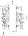
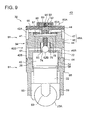
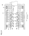
- FIG.2 and FIG.31 show schematic longitudinal sections of the radial piston hydraulic machine according to some embodiments, taken along the axial direction thereof.
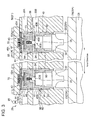
- FIG.3 is a schematic enlarged longitudinal section of a part of FIG.2 .
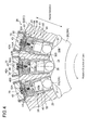
- FIG.4 is a schematic transverse section of a part of the hydraulic machine of FIG.2 , taken along the direction perpendicular to the axial direction of the hydraulic machine.
- a hydraulic machine 20 is provided with a plurality of pistons 22 arranged along the circumferential direction of the hydraulic machine 20 and a cylinder block 26 where a plurality of cylinders 24 is provided to slidably support the plurality of pistons 22, respectively.
- Each of the pistons 22 is configured to be guided by the cylinder 24 and to reciprocate along the radial direction of the hydraulic machine 20.
- volume of a hydraulic chamber 25 formed by the piston 22 and the cylinder 24 changes cyclically.
- the reciprocating motion of the piston 22 which accompanies cyclic volume change of the hydraulic chamber 25 is convertible into a rotational motion of a machine element 29, and vice versa.
- the rotational motion of the machine element 29 which rotates with the rotation shaft 28 of the hydraulic machine 20 is converted into a reciprocating motion of the piston 22, and the volume of the hydraulic chamber 25 changes cyclically to generate high pressure operating oil (pressurized oil) in the hydraulic chamber 25.
- the hydraulic machine 20 is a hydraulic motor
- the reciprocating motion of the piston 22 occurs in response to feeding of the pressurized oil into the hydraulic chamber 25, and then the reciprocating motion is converted into the rotational motion of the machine element 29.
- the rotation shaft 28 of the hydraulic machine 20 rotates with the machine element 29.
- the hydraulic machine 20 is capable of serving as the hydraulic pump or the hydraulic motor as desired.
- the machine element 29 is configured to rotate with the rotation shaft 28 as illustrated in FIG.2 and FIG.31 and is composed of a cam 29A having a cam face contacting a contact part 23 provided on the piston 22.
- at least one bearing 27 may be provided between the cylinder block 26 and the cam (the machine element 29) or the rotation shaft 28 rotating with the cam.
- two bearings 27 are provided between the cylinder block 26 and the rotation shaft 28 rotating with the cam 29A (the machine element 29).
- the cam 29A (the machine element 29) is configured to surround the outer periphery of the cylinder block 26 and to rotate with a housing 21 which is provided to rotate together with the rotation shaft 28. Between the housing 21 and the cylinder block 26, two bearings 27 are provided.
- the contact part 23 is composed of a roller 23A rotatably attached to the piston 22.
- the cam 23A is composed of a ring cam having a plurality of lobes (cam ridge) 31 disposed in the circumferential direction of the hydraulic machine 20 and contacting the plurality of rollers 23A.
- the machine element 29 is a crankshaft which is configured to rotate with the rotation shaft 28 and has at least one crank pin connected to the piston 22 via a connecting rod.
- the cylinder block 26 is provided to rotate together with the rotation shaft 28, and the machine element 29 is provided to surround the cylinder block 26 and is arranged in a stationary state.
- the contact part is provided on its outer side in the radial direction.
- the ring cam may be an outward projecting cam or an inward projecting cam.
- At least one inner oil path 30 (30A, 30B) communicating with a plurality of the hydraulic chambers 25 is formed.
- a plurality of the inner oil paths 30 (30A, 30B) is provided along the axial direction of the hydraulic machine 20, and an annular collecting path 35 (35A, 35B) communicating with each of the plurality of inner oil paths 30 (30A, 30B), is formed in an annular endplate 34.
- the endplate 34 is an annular plate member attached to an end of the cylinder block 26.
- the bearing 27 is provided between the endplate 34 and the rotation shaft 28, and the endplate 34 and the cylinder block 26 can be maintained in a stationary state by a supporting means not shown, without being affected by the rotational motion of the machinery element 29.
- the annular collecting paths 35 (35A, 35B) inside the endplate 34 are, respectively, connected to outer pipes 36 (36A, 36B).
- each of the hydraulic chambers 25 is configured to communicate with the outer pipes 36 (36A, 36B) via the inner oil paths 30 (30A, 30B) and the annular collecting paths 35 (35A, 35B).
- one of the outer pipes 36A and 36B is the high pressure line 12 and the other of the outer pipes 36A and 36B is the low pressure line 14.
- the inner oil path 30A is a high pressure oil path and the inner oil path 30B is the low pressure oil path.
- the inner oil path 30A is the low pressure oil path and the inner oil path 30B is the high pressure oil path.
- the cylinder block 26 includes a plurality of cartridges 38 having the plurality of cylinders 24, respectively, and a cylinder block body 50 having a plurality of cartridge holes 52 into which the plurality of cartridges 38 is inserted, respectively.
- the cartridge 38 is included in a cylinder assembly 43.
- the cylinder block 26 has the function to form the cylinder 24 as the slide part for guiding the piston 22 slidably and the function to form a structure for supporting the cylinder 24.
- the cartridge 38 and the cylinder block body 50 can share the functions expected in the cylinder block 26 (formation of the cylinder and formation of the structure). This enables designing of the cartridge 38 and the cylinder block body 50 according to their respective functions, hence achieving reduced weight of the cylinder block 26 as a whole.
- FIG.5 is an oblique view of the cylinder block 50 according to some embodiments, schematically illustrated with the cartridge 38, the piston 22 and the roller 23A removed from one of the cartridge holes 52.
- the cartridge 38 is a replaceable container which forms the cylinder 24.
- the cartridge 38 includes a cylinder sleeve 80 as well as members to be joined with the cylinder sleeve 80.
- the cylinder sleeve 80 is not particularly restricted as long as the cylinder sleeve 80 includes at least a tubular part (a sleeve body) which forms the cylinder 24.
- the cylinder block body 50 includes at least in part a forged component which is made by forging.
- a forged component which is made by forging.
- at least one inner oil path 30 (30A, 30B) is provided in the forged component 51.
- the forged component 51 excels in liquid tightness and thus, by the inner oil path 30 provided in the forged component 51 of the cylinder block 26, it is possible to supply the operating oil while suppressing leak of the operating oil.
- the forged component 51 is an annular member having both at least one inner oil path 30 (30A, 30B) and a plurality of the cartridge holes 52.
- the forged component 51 has relatively high rigidity and thus, the forged component 51 is capable of withstanding an external force acting on the forged component via the piston 22 and the cylinder sleeve 80. Further, as one form of the external force acting on the forged component 51, there is a pressing force from the machine element (e.g. the cam) 29 configured to cause reciprocation of the piston 22.
- the machine element e.g. the cam
- the forged component 51 is an annular member, it improves the degree of freedom in arranging the inner oil paths 30 (30A, 30B) in the circumferential direction of the forged component 51 and thus it is possible to improve arrangement density of the inner oil paths 30 (30A, 30B) in the forged component 51.
- the cross section of each of the inner oil paths 30 can be reduced, thereby reducing the forged component 51 in thickness. This lowers the production cost of the relatively expensive forged component 51.
- the cylinder block 26 can be replaced per segment.
- positional accuracy of each cylinder 24 with respect to the rotation center of the hydraulic machine 20 decreases.
- the positional accuracy of each cylinder 24 with respect to the rotation center of the hydraulic machine 20 can be improved to some extent. This, however, increases labor for assembling the cylinder block 26.
- replacing of the segments at the site can cause the following issue.
- the wind load impinges on the cylinder block 26 to some extent and thus, immediately after some of the segments are removed, the positions of remaining segments are displaced. This makes it difficult to install new segments.
- At least one inner oil path 30 extends in the cylinder block body 50 along the axial direction of the hydraulic machine 20.
- the inner oil path 30 is configured to extend along the axial direction, it is possible to downsize the cylinder block body 50 in comparison to the case where the inner oil path 30 extends along the radial direction of the hydraulic machine 20.
- the plurality of cartridges 38 is configured to be removable from and insertable into the plurality of cartridge holes 52 of the cylinder block body 50 along the radial directions, respectively.
- “to be removable from and insertable into the plurality of cartridge holes 52 of the cylinder block body 50 along the radial directions” includes the case where the plurality of cartridges 38 is removed in the direction of moving away from a shaft of the hydraulic machine 20 as well as the case where the plurality of cartridges 38 is inserted in the direction of moving toward the shaft of the hydraulic machine 20.
- the cylinder block 26 and the cartridges 38 are arranged on an outer peripheral side with respect to the cam 29A and the rotation shaft 28 that are configured to rotate, and the cartridges 38 (the cylinder assemblies 43) are configured to be removable from and insertable into the cartridge holes 52 in the direction along the direction of moving away from the shaft of the hydraulic machine 20.
- the cylinder block 26 and the cartridges 38 are arranged on an inner peripheral side with respect to the housing 21 and the cam 29A that are configured to rotate with the rotation shaft 28, and the cartridges 38 (the cylinder assemblies 43) are configured to be removable from and insertable into the cartridge holes 52 in the direction along the direction of moving closer to the shaft of the hydraulic machine 20.
- the plurality of cartridges 38 includes a plurality of cylinder sleeves 80.
- Each of the cartridges 38 includes a low pressure valve and a high pressure valve which are described later in details.
- the cartridge 38 is configured to be removable from and insertable into the cartridge hole 52 of the cylinder block body 50 together with the piston 22 along the radial direction.
- FIG.6 is a schematic section of the cylinder assembly 43 arranged in the cartridge hole 52.
- the cylinder sleeve 80 forms the slide part with respect to the piston 22.
- the cylinder sleeve 80 and/or the piston 22 can be replaced, and the cylinder block body 50 does not basically need to be replaced.
- the cartridge 38 to be replaced is removed from the cartridge hole 52 of the cylinder block body 50 along the radial direction of the hydraulic machine 30 and then a new cartridge 38 or the cartridge 38 which includes a repaired cylinder sleeve 80 and/or piston 22 is inserted into the cartridge hole 52. This facilitates the replacement work. Therefore, the maintenance of the radial piston hydraulic machine 20 becomes simple.
- the shape of the cylinder block of the radial piston hydraulic machine is normally a combination of a trapezoid, an arc, an inclined surface, etc.
- the difficulty in machining the cylinder block is high.
- the cylinder block used for the radial piston hydraulic machine as the drive train for the wind turbine generator is large and has difficulty in machining.
- the above hydraulic machine 20 is configured such that the cylinder block body 50 and the cylinder sleeves 80 having the cylinders 24 are separately provided.
- the above hydraulic machine 20 is configured such that the cylinder block body 50 and the cylinder sleeves 80 having the cylinders 24 are separately provided.
- the plurality of pistons 22 includes a plurality of end-stops (engagement means) for restricting the plurality of pistons 22 from coming out from the plurality of cylinder sleeves 80, respectively.
- the plurality of pistons 22 is engageable with the plurality of cylinder sleeves 90 by means of the plurality of end-stops (engagement means), respectively. With this configuration, the plurality of pistons 22 is restricted from coming out from the plurality of cylinder sleeves 80, respectively and this prevents the pistons 22 from coming out from the cylinder sleeves 80, respectively, during the replacement work of the cylinder sleeves 80.
- an engagement screw 54 and an engagement groove 55 are provided as the end-stops (engagement means) for engaging the piston 22 with the cylinder sleeve 80.
- the engagement groove 55 is provided on a side of the piston 22 and extends in the axial direction of the cylinder 24.
- the engagement groove 55 opens at a side face of the piston 22.
- the engagement screw 54 is screwed into a screw hole penetrating the cylinder sleeve 80, and a tip of the engagement screw 54 is disposed in the engagement groove 55.
- the engagement screw 54 restricts the piston 22 from coming out of the cylinder sleeve 80 while allowing reciprocating motion of the piston 22 in the axial direction of the cylinder 24.
- the engagement groove 55 forms an engagement part of the piston 22 with respect to the cylinder sleeve 80.
- the engagement screw 54 and the engagement groove 55 are configured so that the engagement screw 54 and the piston 22 (a wall of the engagement groove 55) do not collide against each other during the reciprocating motion of the piston 22. More specifically, an area of the engagement groove 55 along the axial direction of the piston 22 is set in accordance with a stroke of the piston 22 so that the engagement screw 54 does not collide against the wall of the engagement groove 55 on the contact part 23 side (the roller 23 side) when the piston 22 is at a top dead center and that the engagement screw 54 does not collide against the wall of the engagement groove 55 on the hydraulic chamber 25 side when the piston 22 is at a bottom dead center.
- an engagement plate 56 is provided as the end-stop (engagement means) for engaging the piston 22 with the cylinder sleeve 80, an engagement plate 56 is provided.
- the engagement plate 56 has a strip shape and is fixed to a pressure receiving face of the piston 22 (a piston head top face with screws. Both ends of the engagement plate 56 projects slightly past the outer edge of the piston 22.
- a reduced diameter part is provided in the cylinder sleeve 80. By abutting on the reduced diameter part of the cylinder sleeve 80, the engagement plate 56 restricts the piston 22 from coming out from the cylinder sleeve 80.
- the engagement plate 56 forms the engagement part of the piston 22 with respect to the cylinder sleeve 80.
- the engagement plate 56 is configured so that the engagement plate 56 does not collide against the cylinder sleeve 80 during the reciprocating motion of the piston 22.
- the thickness of the engagement plate 56 and the location of the reduced diameter part of the cylinder sleeve 80 are set in accordance with a stroke of the piston 22 so that there is a clearance between a top face of the engagement plate 56 and a wall of the hydraulic chamber 25 on an opposite side of the hydraulic chamber 25 from the contact part 23 (the roller 23A) when the piston 22 is at the top dead center and that there is clearance between a bottom face of the engagement plate 56 and the top face of the reduced diameter part of the cylinder sleeve 80 when the piston 22 is at a bottom dead center.
- the engagement plate 56 is inserted in the cylinder sleeve 80 prior to insertion of the piston 22, and once the piston 22 is inserted, the engagement plate 56 is screwed to the piston 22 from an opening provided in the cylinder sleeve 80.
- a hole which is large enough to insert the engagement plate 56 through may be formed in the cylinder sleeve 80, and the hole may be closed by a closing member 57 of a screw type.
- a snap ring 58 is provided on an outer periphery of the piston 22 to serve as the end-stop (engagement means) for engaging the piston 22 with the cylinder sleeve 80.
- the snap ring 58 is fitted to the outer periphery of the piston 22. By abutting on the reduced diameter part of the cylinder sleeve 80, the snap ring 58 restricts the piston 22 from coming out from the cylinder sleeve 80.
- the snap ring 58 forms an engagement part of the piston 22 with respect to the cylinder sleeve 80.
- the snap ring 58 is configured so that the snap ring 58 does not do not collide against the cylinder sleeve 80 during the reciprocating motion of the piston 22. More specifically, the mounting position of the snap ring 58 and the location of the reduced diameter part of the cylinder sleeve 80 are set in accordance with a stroke of the piston 22 so that there is a clearance between the snap ring 58 and the top face of the reduced diameter part of the cylinder sleeve 80 when the piston 22 is at the bottom dead center.
- the cylinder sleeve 80 may be configured to be dividable so that the snap ring 58 can be fitted therein.
- the plurality of cartridges 38 is configured to be removable together with the plurality of pistons 22 and the plurality of rollers 23A from the plurality of cartridge holes 52 of the cylinder block body 50 to an opposite side of the ring cam contacting the rollers 23A along the radial direction and configured to be insertable into the plurality of cartridge holes 52 of the cylinder block body 50 from the opposite side of the ring cam along the radial directions, respectively.
- the cartridge 38 can be removed from and inserted into the cartridge hole 52 together with the piston 22 and the roller 23A by using a space on the opposite side of the cylinder block 26 from the ring cam. As a result, it is possible to efficiently perform the replacement work of the piston 22 or the roller 23A. This facilitates maintenance of the hydraulic machine 20.
- the plurality of rollers 23A is engageable with the plurality of pistons 22 so as to restrict the plurality of rollers 23A from coming out from the plurality of pistons 22 in an axial direction of the plurality of pistons 22, respectively. With this configuration, during the replacement or the like of the rollers 23A, the rollers 23A are prevented from coming out from the pistons 22 and thus the replacement work is facilitated.
- two arms 59 are provided to the piston 22 as engagement means for engaging the piston 22 with the roller 23A.
- These two arms 59 have arc faces.
- the arc faces define an almost cylindrical space which is perpendicular to the axial direction of the piston 22, and the roller 23A is inserted coaxially in the space. Tips of these two arms 59 are set apart from each other so as not to interfere with contacting of the roller 23A and the cam 29A.
- These two arms 59 support the roller 23A rotatably and restricts the roller 23A from coming out from the piston 22 in the axial direction of the piston 22.
- the arms 59 are configured so that the arms 59 and the cylinder sleeve 80 do not collide against each other during the reciprocating motion of the piston 22. More specifically, the lengths of the arms 59 are set in accordance with a stroke of the piston 22 so that there is clearance between a top face of the arm 59 and the cylinder sleeve 80 when the piston 22 is at the top dead center.
- the plurality of cartridge holes 52 has a size greater than the plurality of rollers 23A, respectively.
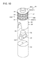
- FIG.10 is a schematic oblique view of the cartridge hole 52 and the cylinder assembly 43. In the drawing, the piston 22 and the roller 23A are removed from the cylinder sleeve 80.
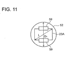
- FIG.11 is a schematic plan view of the cartridge hole 52 and the roller 23A.
- each of the plurality of cartridge holes 52 has a circular cross sectional shape and a diameter D1 which is greater than a diagonal length L of each of the plurality of rollers 23A. With this configuration, it is possible to remove the roller 23A from the cylinder block body 50 via the cartridge hole 52.
- a notched portion 63 corresponding to each end of the roller 23A is formed in the roller 23A side end of the cylinder sleeve 80.
- the notched portion 63 is configured to receive each end of the roller 23A and allows the reciprocating motion of the piston 22.
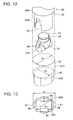
- FIG.12 is a schematic oblique view of the cartridge hole 52 and the cylinder assembly 43 according to another embodiment. The drawing, however, illustrates only a part of the cylinder sleeve 80 and the piston 22 and the roller 23A are removed from the cylinder sleeve 80.
- FIG.13 is a schematic plan view of the roller 23A and the cartridge hole 52.
- each of the plurality of cartridge holes 52 includes a first portion 52A and a second portion 52B.
- the first portion 52A has a circular cross sectional shape and provided in a first region of the cylinder block body 50 corresponding to each of the plurality of hydraulic chambers 25 formed, respectively, by the plurality of pistons 22 and the plurality of cylinders 24.
- the second portion 52B is provided in a second region of the cylinder block body 50 which is nearer to the roller 23A than the first region.
- the second portion 52B has a cross sectional shape where at least a notched portion 61 corresponding to each end of each of the plurality of rollers 23A is added to a circular cross-section whose diameter D2 is less than a diagonal length L of each of the plurality of rollers 23A.
- the roller 23A can be removed through the second portion 52B and the first portion 52A of the cartridge hole 52.
- the cross section of the second portion 52B is smaller than the cross section of the first portion 52A, and a thickness of a section of the cylinder block body 50 which surrounds the second portion 52B is made thick.
- the strength of the cylinder block body 50 can be improved in such a range that does not interrupt passing of the roller 23A through the cartridge hole 52.
- two side plates 69 are attached to the piston 22 so as to restrict the movement of the roller 23A in the axial direction. These two side plates 69 clamp the roller 23A from both sides in the axial direction so that the roller 23A is relatively rotatable to the side plates 69.
- the notched portion 61 corresponds to the side plates 69 as well and is formed by a plurality of arc faces.
- each of the plurality of cylinder sleeves 80 includes a first sleeve portion 80A and a second sleeve portion 80B.
- a stepped portion 65 is provided between the first sleeve portion 80A and the second sleeve portion 80B.
- the cylinder sleeve 80 can be positioned in the cartridge hole 52 using the stepped portion 65 of the cylinder sleeve 80. More specifically, by abutting the stepped portion of the cylinder sleeve 80 onto a stepped portion 67 of the cartridge hole 52, positioning of the cylinder sleeve 80 inside the cartridge hole 52 can be performed. Further, corresponding to the stepped portion 65, a thickness of the first sleeve portion 80A can be made greater than that of the second sleeve portion 80B. As a result, the cylinder sleeve 80 can possess high strength.
- the cylinder block 26 further comprises a plurality of cover members 70 attached to the cylinder block body 50 so as to restrict the plurality of cartridges 38 inserted in the plurality of cartridge holes 52 from coming out from the cylinder block body 50 along the radial direction, respectively.
- the plurality of cover members 70 is fixed to the cylinder block body 50by bolts, for instance.
- the hydraulic machine 20 further comprises a plurality of valves 60 (60A, 60B) disposed between the plurality of hydraulic chambers 25 and each of the low-pressure line (not shown) and the high pressure line (not shown).
- the low pressure line and the high pressure line are communicable with the plurality of hydraulic chambers 25.
- the plurality of hydraulic chambers 25 are formed by the plurality of pistons 22 and the plurality of cylinders 24, respectively.
- Either the plurality of the valves 60A or the plurality of the valves 60B is a plurality of low-pressure valves disposed between the low-pressure line and the plurality of hydraulic chambers 25, respectively, and configured to switch communication states of the plurality of hydraulic chambers 25 with the low-pressure line, respectively.
- the other of the plurality of the valves 60A or the plurality of the valves 60B is a plurality of high-pressure valves disposed between the high-pressure line and the plurality of hydraulic chambers 25, respectively, and configured to switch communication states of the plurality of hydraulic chambers 25 with the high-pressure line, respectively.
- the inner oil path 30A illustrated in FIG.3 and FIG.4 is the low pressure oil path communicating with the low pressure line and the valve 30A is the low pressure valve.
- the outer oil path 36B illustrated in FIG.3 is the high pressure oil path communicating with the high pressure line and the valve 30B is the high pressure valve.
- the inner oil path 30A illustrated in FIG.3 and FIG.4 is the high pressure oil path communicating with the high pressure line and the valve 30A is the high pressure valve.
- the outer oil path 36B illustrated in FIG.3 is the low pressure oil path communicating with the low pressure line and the valve 30B is the low pressure valve.
- the plurality of cartridges 38 comprising the plurality of valves 60 (60A, 60B) is configured to be removable and insertable with respect to the plurality of cartridge holes 52 of the cylinder block 50 along the radial direction.
- the cartridge 38 is configured to be removable and insertable with the valves 60 (60A, 60B) with respect to the cartridge hole 52.
- the valves (60A, 60B) can be removed with the cartridge 38 from the cartridge hole 52. Therefore, the maintenance work of the valves (60A, 60B) can be performed easily.
- the plurality of cylinders 24 has a center axis (the cylinder axis) which coincides with a center axis of the plurality of cylinder sleeves 80, respectively.
- the inner peripheral surface and the outer peripheral surface of the cylinder sleeve 80 can be formed by lathe machining using a common center hole, and this enhances the manufacturability of the cylinder sleeve 80. Therefore, the manufacturability of the hydraulic machine 20 is further enhanced.
- the cartridge 38 comprises at least one oil groove 41 provided in the outer peripheral surface of the cartridge 38 and opening to the at least one inner oil path 30 (30A, 30B).
- the oil groove 41 is formed in the outer peripheral surface of the cylinder sleeve 80.
- At least one oil path 30 includes a plurality of inner oil paths 30 extending along the axial direction of the hydraulic machine 20, and at least one oil groove 41 opens to at least two of the plurality of inner oil paths 30.
- At least one oil groove 41 includes an annular grooves (42A, 42B) continuous over the entire circumference of the outer peripheral surface of the cartridge 38.
- the annular groove 42 forms the oil groove on the outer peripheral surface of the cylinder sleeve 80 and opening to the inner oil path 30 provided in the cylinder block body 50. This improves the degree of freedom in arranging the inner oil path 30 with respect to the cartridge 38.
- the annular grooves 42 are formed over the entire circumference of the outer peripheral surface of the cylinder sleeve 80.
- the hydraulic machine 20 further comprises a plurality of seal members which is provided in the outer peripheral surface of the cartridge 38 on both sides of the annular groove so as to seal the plurality of annular grooves 42, respectively.
- the annular groove 42 is sealed on both sides thereof by the seal member 44, thereby achieving excellent liquid tightness.
- the seal member 44 is configured to seal a gap between the cartridge 38 and the cartridge hole 52 that are annular.
- the seal member 44 may be an O-ring made of an elastic material, for instance.
- At least one inner oil path 30 provided in the forged component 51 includes an oil supply path for supplying the operating oil to the hydraulic chamber 25 and an oil discharge path for discharging the operating oil from the hydraulic chamber 25.
- one of the inner oil paths 30A and 30B is the oil supply path and the other is the oil discharge path.
- the oil supply path 30A and the oil discharge path 30B provided in the cylinder block 26 extend along the axial direction of the hydraulic machine 20.
- both of the inner oil paths 30A and 30B extend in the axial direction and thus, it is possible to prevent increase in size of the cylinder block 26 and also simplify a piping structure connected to the inner oil path 30A and the inner oil path 30B.
- the inner oil path 30A and the inner oil path 30B provided in the cylinder block 26 are at different positions in the radial direction of the hydraulic machine 20.
- the inner oil path 30A and the inner oil path 30B are at different positions in the radial direction and are not arranged in parallel at the same radial position.
- it requires only a small space for the inner oil path 30A and the inner oil path 30B, and it is not necessary to increase the distance between the cylinders 24.
- it is possible to prevent increase in size of the cylinder block 26.
- it is possible to increase the number of the cylinders 24 arranged in the circumferential direction as the space for the inner oil path 30A and the inner oil path 30B is saved. As a result, it is possible to suppress pulsation and vibration in the case where the number of the cylinders 24 is increased.
- communication paths 46 are provided for communication between the inner oil paths 30 (30A, 30B) and the hydraulic chamber 25.
- the valve 60 60A, 60B is provided for switching the communication state between the inner oil path 30 (30A, 30B) of the valve block and the hydraulic chamber 25.
- One of the communication paths 46 (46A, 46B) is a low pressure communication path for communication between the hydraulic chamber 25 and the low pressure oil path via the low pressure valve, and the other of communication paths 46 (46A, 46B) is a high pressure communication path for communication between the hydraulic chamber 25 and the high pressure oil path via the high pressure valve.
- the inner oil path 30 (30A, 30B) and the communication path 46 (46A, 46B) are connected to each other via the annular groove 42 (42A, 42B).
- the plurality of valves 60 comprises a plurality of oil supply valves 60A for switching a supply state of the operating oil to the plurality of hydraulic chambers 25, respectively, and a plurality of oil discharge valves 60B for switching a discharge state of the operating oil from the plurality of hydraulic chambers 25, respectively.
- the plurality of oil supply valves 60A and the plurality of oil discharge valve 60B are, respectively, included in the plurality of cartridges 38.
- One of the oil supply valve 60A or the oil discharge valve 60B is provided between the hydraulic chamber 25 and the low pressure line (the outer pipe 36), and serves as the low pressure valve for switching the communication state between the hydraulic chamber 25 and the low pressure line (outer pipe 36).
- the other of the oil supply valve 60A or the oil discharge valve 60B is provided between the hydraulic chamber 25 and the high pressure line (the outer pipe 36), and serves as the high pressure valve for switching the communication state between the hydraulic chamber 25 and the high pressure line (outer pipe 36).
- the cartridge 38 including the oil supply valve 60A and the oil discharge valve 60B is arranged in the cartridge hole 52, and compared to the case where the oil supply valve 60A and the oil discharge valve 60B are arranged in a place different from the cartridge hole 52, the installation space for the oil supply valve 60A and the oil discharge valve 60B is reduced. As a result, it is possible to downsize the cylinder block body 50 and to downsize the radial piston hydraulic machine 20.
- the oil supply valve 60A and the oil discharge valve 60B are retained by a valve block which is described later, in the cartridge 38.
- valve block 81 including the oil supply valve 60A and the oil discharge valve 60B is incorporated in the cartridge 38.
- the oil supply valve 60A and the oil discharge valve 60B are not arranged between adjacent two of the cartridges 38, it is no longer necessary to provide the valve installation space for the oil supply valve 60A and the oil discharge valve 60B in the cylinder block body 50. Therefore, it is possible to achieve improved installation density of the cartridges 38 in the cylinder block 26.
- the at least one annular groove 42 includes an oil supply groove 42A opening to the oil supply path 30A inside the forged component 51 and an oil discharge groove 42B opening to the oil discharge path 30B inside the forged component 51.
- the communication path 46 includes an oil supply communication path 46A for communication between the hydraulic chamber 25 and the oil supply groove 42A via the oil supply valve 60A, and an oil discharge communication path 46B for communication between the hydraulic chamber 25 and the oil supply groove 42B via the oil discharge valve 60B.
- one of the oil supply communication path 46A or the oil discharge communication path 46B is the low pressure communication path for communication between the hydraulic chamber 25 and the low pressure oil path (inner oil path 30), and the other one of the oil supply communication path 46A or the oil discharge communication path 46B is the high pressure communication path for communication between the hydraulic chamber 25 and the high pressure oil path (inner oil path 30).
- the oil supply communication path 46A and the oil discharge communication path 46B can reliably communicate with the oil supply path 30A and the oil discharge path 30B, respectively
- a first communication path for communication between the hydraulic chamber 25 and the oil supply path 30A and a second communication path for communication between the hydraulic chamber 25 and the oil discharge path 30B are provided.
- the first communication path includes the oil supply groove (first annular groove) 42A provided in the outer peripheral surface of the cartridge 38 and opening to the oil supply path 30A.
- the second communication path includes the oil discharge groove (second annular groove) 42B provided at a position farther from the oil supply groove 42A in the radial direction in the outer peripheral surface of the cartridge 38 and opening to the oil discharge path 30B.
- one of the first communication path or the second communication path is the low pressure communication path for communication between the hydraulic chamber 25 and the low pressure oil path (inner oil path 30), and the other one of the first communication path or the second communication path is the high pressure communication path for communication between the hydraulic chamber 25 and the high pressure oil path (inner oil path 30).
- the oil supply path 30A can reliably communicate with the hydraulic chamber 25 with a simple configuration. Further, with this configuration, by providing the oil discharge groove 42B opening to the oil discharge path 30B at a radial position different from the oil supply groove 42A in the outer peripheral surface of the cartridge 38, the oil discharge path 30B can reliably communicate with the hydraulic chamber 25 with a simple configuration.
- the first communication path is configured so that the hydraulic chamber 25 communicates with at least one oil supply path 30A via the oil supply valve 60A
- the second communication path is configured so that the hydraulic chamber 25 communicates with at least one oil discharge path 30B via the oil discharge valve 60B.
- the oil supply valve 60A and the oil discharge valve 60B are arranged to be aligned in the radial direction of the hydraulic machine 20.
- the oil supply valve 60A and the oil discharge valve 60B are arranged in the cartridge 38 in such a state that oil supply valve 60A and the oil discharge valve 60B are aligned in the axial direction of the cartridge 38.
- the oil supply valve 60A and the oil discharge valve 60B are aligned in the radial direction of the hydraulic machine 20, and it is possible to save the valve installation space in the plane perpendicular to the radial direction of the hydraulic machine 20.
- valve block 26 (the cartridge 38) in the plane perpendicular to the radial direction of the hydraulic machine 20 and also downsize the cylinder block body 50 while securing enough distance between the adjacent cartridges 38 in the circumferential direction to maintain rigidity of the cylinder block body 50 or the like.
- the oil supply valve 60A and the oil discharge valve 60B are incorporated in the cartridge 38, it is possible to prevent coming out of the oil supply valve 60A and the oil discharge valve 60B all together from the cartridge hole 52 using the cover member 70.
- the oil supply valve 60A and the oil discharge valve 60B are incorporated in the cartridge 38, it is possible to reduce the machining work on the cylinder block body 50, reduce the working man-hours and also prevent rigidity reduction of the cylinder block body 50 due to machining.
- valve element 62A of the oil supply valve 60A lays over the valve element 62B of the oil discharge valve 60B with respect to the radial direction of the hydraulic machine 20.
- valve element 62A of the oil supply valve 60A overlaps the valve element 62B of the oil discharge valve 60B in the radial direction of the hydraulic machine 20, it is possible to reduce the installation space for the oil supply valve 60A and the oil discharge valve 60B within the cartridge hole 52.
- the oil supply groove 42A and the oil discharge grove 42B are provided at different positions in the radial direction of the hydraulic machine 20 on the outer peripheral surface of each of the cartridges 38.
- the plurality of oil supply valves 60A is provided at a position farther from the plurality of hydraulic chambers 25 than the plurality of oil discharge valves 60B, respectively.
- the first communication path for communication between the oil supply path 30A and the hydraulic chamber 25 includes at least one oil supply radial flow path (first flow path) 48 extending in the radial direction from each of the hydraulic chambers 25 toward the valve element 62A of each of the oil supply valves 60A.
- the second communication path for communication between the oil discharge path 30B and the hydraulic chamber 25 includes at least one oil discharge perpendicular flow path (second flow path) 72 extending along the direction perpendicular to the at least one first flow path while avoiding the at least one first flow path.
- the oil supply radial flow path (first flow path) 48 is a radial flow path
- the oil discharge perpendicular flow path (second flow path) 72 is a perpendicular flow path.
- the hydraulic chamber 25 can communicate with the oil supply path 30A via the oil supply valve 60A and with the oil discharge valve 60B via the oil discharge path 30B.
- the first communication path includes at least one oil supply perpendicular flow path (third flow path) 47 configured so that the at least one first flow path 48 communicates with the oil supply groove 42A via each of the oil supply valves 60A.
- Each first flow path 48 (a part of the first communication path) extending along the radial direction of the hydraulic machine 20 may be formed by cutting by use of a drill and/or by cutting and/or grinding by use of other machine tool or tools. Further, each first flow path 48, extending along the radial direction of the hydraulic machine 20 has substantially a single diameter, and the diameters of each of the firstflow paths 48 are substantially constant in the longitudinal direction of the first flow paths 48. Furthermore, the walls of the first flow path 48 are substantially parallel to each other. Moreover, the first flow path 48 extending along the radial direction of the hydraulic machine 20 may cross but not intersect with the oil discharge perpendicular flow path (the second flow path) 72 which is a region of different fluid pressure.
- FIG. 14 is a schematic section taken along line XIV-XIV of FIG.6 .
- FIG.15 is a schematic section taken along line XV-XV of FIG.6 .
- a plurality of the first flow paths 48 and a plurality of the third flow paths 47 are arranged around the center axis of the cylinder sleeve 80. Further, as illustrated in FIG.15 , a plurality of the second flow paths 72 extends in a space between the plurality of the first flow paths 48.
- the above-described hydraulic machine 20 is a hydraulic pump
- the oil supply valve 60A when the oil supply valve 60A is opened, the operating oil from the oil supply path 30A inside the forged component 51 is introduced into the hydraulic chamber 25 via the oil supply groove 42A and the oil supply communication path 46A. Then, the operating oil introduced to the hydraulic chamber 25 is compressed and pressurized by volume reduction of the hydraulic chamber 25 in response to the movement of the piston 22 moving from the bottom dead center to the top dead center.
- the high pressure operating oil (pressurized oil) produced in this manner is then drawn, by opening of the oil discharge valve 60B, to the oil discharge path 30B inside the forged component 51 via the oil discharge communication path 46B and the oil discharge groove 42B.
- the above-described hydraulic machine 20 is a hydraulic motor
- the oil supply valve 60A when the oil supply valve 60A is opened, the high pressure operating oil (pressurized oil) from the oil supply path 30A inside the forged component 51 is introduced into the hydraulic chamber 25 via the oil supply groove 42A and the oil supply communication path 46A.
- the piston 22 By this operating oil introduced to the hydraulic chamber 25, the piston 22 is caused to move from the top dead center to the bottom dead center.
- the operating oil in the hydraulic chamber 25 is drawn, by opening of the oil discharge valve 60B, to the oil discharge path 30B inside the forged component 51 via the oil discharge communication path 46B and the oil discharge groove 42B.
- each of the plurality of discharge valves 60B comprises at least one spherical valve element 62B arranged in a valve chamber 75 communicating with each of the hydraulic chambers 25 via at least one valve hole 74, and at least one energizing member 76 for energizing the at least one spherical valve element 62B toward the at least one valve hole 74.
- At least one first flow path 48 is arranged avoiding the valve chamber 75 where the at least one spherical valve element 62B is arranged.
- the oil discharge valve 60B is a check valve having the spherical valve element 62B and has a simple configuration compared to an electromagnetic valve.
- the oil discharge valve 60A can be easily connected to the hydraulic chamber 25 while avoiding the oil discharge valve 60B.
- the oil discharge valve 60B is not an electromagnetic valve, the oil discharge valve 60B does not require electrical connection. Thus, disposition of the oil discharge valve 60B which is a check valve near the hydraulic chamber 25 does not complicate the wiring.
- a compression coil spring may be used as the energizing member 76.
- the plurality of hydraulic chambers 25, the plurality of oil discharge valves 60B, and the plurality of oil supply valves 60B are arranged, respectively, in this order from the inner circumferential side toward the outer circumferential side of the cylinder block 26.
- the plurality of oil supply valves 60A are electromagnetic valves, respectively.
- the at least one spherical valve element 62B is one spherical valve element 62B disposed on the center axis of each of the cylinders 24, and the at least one first flow path 48 is arranged to surround the valve chamber 75 where the spherical valve element is arranged.
- valve element 62B is a spherical valve element and thus, the valve chamber 75 can be reduced in size. Therefore, the space for the first flow path 48 can be easily secured around the valve chamber 75.
- FIG.16 is a schematic section of the cylinder assembly 43 according to another embodiment.
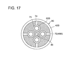
- FIG.17 is a schematic section taken along line XVII-XVII of FIG.16 .
- a plurality of the spherical valve elements 62B and a plurality of the valve holes 74 are arranged in a rotation symmetric fashion with respect to the center axis of each of the cylinders 24.
- FIG.18 is a schematic section of the cylinder assembly 43 according to yet another embodiment.
- FIG.19 is a schematic section taken along line XIX-XIX of FIG.18 .
- the plurality of oil supply valves 60A is arranged at the position farther from the plurality of hydraulic chambers 25 than the plurality of oil discharge valves 60B, respectively.
- the first communication path for communication between the oil supply path 30A and the hydraulic chamber 25 and the second communication path for communication between the oil discharge path 30B and the hydraulic chamber 25 share a common flow path 78 extending from the hydraulic chamber along the radial direction of the hydraulic machine 20.
- the first communication path includes at least one oil supply perpendicular flow path (fourth flow path) 47 extending along the direction perpendicular to the common flow path 78 so that the common flow path 78 communicates with the oil supply groove 42A via each of the oil supply valves 60A.
- the second communication path includes at least one oil discharge perpendicular flow path (fifth flow path) 72 extending along the direction perpendicular to the common flow path 78 so that the common flow path 78 communicates with the oil discharge groove 42B via each of the oil discharge valves 60B.
- the common flow path 78 can communicate with the oil supply grove 42B via the oil discharge valve 60B and with the oil discharge groove 42B via the oil discharge valve 60B with a simple configuration.
- each of the plurality of discharge valves 60B comprises the at least one spherical valve element 62B arranged in the valve chamber 75 communicating with the common flow path 78 via the at least one valve hole 74, and the at least one energizing member 76 for energizing the at least one spherical valve element 62B toward the at least one valve hole 74.
- the oil discharge valve 60B is a check valve having the spherical valve element 62B and has a simple configuration compared to an electromagnetic valve.
- the oil discharge valve 60A can be easily connected to the hydraulic chamber 25 while straddling the oil discharge valve 60B.
- the oil discharge valve 60B is not an electromagnetic valve, the oil discharge valve 60B does not require electrical connection. Thus, disposition of the oil discharge valve 60B which is a check valve near the hydraulic chamber 25 does not complicate the wiring.
- each of the plurality of cartridges 38 includes the cylinder sleeve 80 and the valve block 81.
- the cylinder sleeve has almost cylindrical shape and forms the cylinder 24.
- the valve block 81 is configured to close one end of the cylinder sleeve 80.
- the cartridge 38 is configured to be separable into a first segment 40 and a second segment 85.
- the cylinder sleeve 80 is mainly formed by the first segment 40 and the valve block 81 is formed by a part of the first segment 40 and the second segment 85.
- valve block 81 the supply valve 60A and the supply valve 60B are incorporated.
- the valve block 81 is provided astride the first segment 40 and the second segment 85.
- One of the oil supply valve 60A or the oil discharge valve 60B, which is nearer to the hydraulic chamber 25 is incorporated in the first segment 40 and the other of the oil supply valve 60A or the oil discharge valve 60B, which is farther from the hydraulic chamber 25, is incorporated in the second segment 85 formed separately from the first segment 40.
- the oil discharge valve 60B is incorporated at an end part 84 of the first segment 40. More specifically, in the first segment 40, a bottomed hole extends along the axial direction of the cylinder sleeve 80 to open to the hydraulic chamber 25 side.
- the valve chamber 75 of the oil discharge valve 60B is formed by the bottomed hole.
- a sleeve 83 forming the valve hole 74 and having a valve seat is screwed. The valve element 62B is prevented from coming out from the valve chamber 75 by the valve seat.
- a spring hole forming a spring seat is provided in a bottom face of the bottomed hole.
- the energizing member 76 one end of a compression coil spring is accommodated in the spring hole.
- the cartridge 38 includes the second segment 85 which is to be attached to the first segment 40.
- One of the oil supply valve 60A or the oil discharge valve 60B, which is farther from the hydraulic chamber 25, is incorporated in the second segment 85.
- the oil supply valve 60A is incorporated in the second segment 85.
- the second segment 85 is arranged in the cartridge hole 52 to be adjacent to the end part of the first segment 40.
- a depressed portion of a columnar shape is formed coaxially.
- the second segment 85 has a stepped cylindrical shape constituted of a small diameter part and a large diameter part and is arranged coaxially with the first segment 40.
- the small diameter part of the second segment 85 is disposed on the first segment 40 side and fitted to an opening of the depressed portion of the end part 84 of the first segment.
- the opening of the depressed portion of the end part 84 of the first segment 40 is closed by the small diameter part of the second segment 85, and a valve chamber 87 for the valve element 62A is formed in a gap between the depressed portion and the small diameter part.
- the oil supply radial flow path 48 penetrates the end part 84 of the first segment 40 in the axial direction of the cylinder sleeve 80 and opens at the depressed portion of the end part 84 of the first segment 40.
- a plurality of the oil supply perpendicular flow paths 47 is radially provided in the small diameter part of the second segment 85.
- a plurality of valve holes 88 is provided in the small diameter part of the second segment 84 so that inner ends of the plurality of oil supply perpendicular flow paths 47 communicate with an outer end face of the small diameter part of the second segment 85.
- the plurality of valve holes 88 extends in the axial direction of the small diameter part.
- the oil supply valve 60A is a poppet valve, and the annular valve seat for the valve element 62A is provided on the outer end face of the small diameter part of the second segment 85 n a region where the valve holes 88 open.
- a shaft part of the valve element 62A penetrates the small diameter part of the second segment 85 in the axial direction, and an end of the shaft part is disposed in a large diameter part of the second segment 85.
- an armature 89 is integrally provided.
- the armature 89 is arranged to freely reciprocate in an interior of the large diameter part of the second segment 85.
- a core 90 and a solenoid 92 are fixed to the interior of the large diameter part of the second segment 85.
- a compression coil spring is provided as the energizing member 94.
- the energizing member 94 applies force to and may move the valve element 62A in the direction of away from the valve seat in the axial direction of the cylinder sleeve 80.
- the energizing coil typically moves the valve element 62A when the solenoid 92 is de-energized.
- the oil supply valve 60A by supplying electric power to the solenoid valve 92, the armature 89 is attracted toward the core 90 against the energizing force of the energizing member 94, thereby opening the oil supply valve 60A.
- a transverse hole is provided in the end part 84 of the first segment so that the common flow path 78 communicates with the outer peripheral surface of the first segment 40.
- the transverse hole extends in the direction perpendicular to the axis of the cylinder sleeve 80.
- the sleeve 83 and a closing member 95 is screwed.
- the valve chamber 75 for accommodating the valve element 62B is formed.
- a bottomed spring hole forming the spring seat is formed in an inner end face of the closing member 95A.
- an end of the compression spring as the energizing member 76 is accommodated.
- the compression coil spring as the energizing member 76 is configured to energize the valve element 62 toward the valve hole 74 in the direction perpendicular to the axis of the cylinder sleeve 80.
- the spherical valve element 62B and the compression coil spring 76 serving as the energizing member 76 are aligned in the direction perpendicular to the axial direction of the cylinder sleeve 80.
- the length of the oil discharge valve 60B can be reduced in the axial direction of the cylinder sleeve 80.
- the dead space in the periphery of the hydraulic machine 20 can be reduced, and the efficiency of the hydraulic machine 20 can be enhanced.
- a plurality of the spherical valve element 62B may be provided and, similarly to the cylinder assembly 43 illustrated in FIG.18 , the plurality of the spherical valve elements 62B and a plurality of the compression coil springs 76 serving as the energizing members 76 may be aligned respectively in the direction perpendicular to the axial direction of the cylinder sleeve 80.
- this configuration it is possible further reduce the length of the discharge valve 60B in the axial direction of the cylinder sleeve 80. As a result, the dead space in the periphery of the hydraulic machine 20 can be reduced, and the efficiency of the hydraulic machine 20 can be enhanced.
- a plurality of axial hole arrays 53 is provided in the circumferential direction of the hydraulic machine 20.
- Each of the axial hole arrays 53 is formed by a plurality of the cartridge holes 52 aligned along the axial direction of the hydraulic machine 20.
- a plurality of the oil supply paths 30A and a plurality of oil discharge paths 30B extend along the axial direction of the hydraulic machine 20 as illustrated in FIG.2 to FIG.4 .
- Each of the oil supply paths 30A and each of the oil discharge paths 30B formed in the forged component 51 open to the oil supply grooves 42A and the oil discharge grooves 42B of a plurality of the cartridges 38 inserted in a plurality of the cartridge holes 52 belonging to each of the plurality of axial hole arrays 53, and communicate with a plurality of the hydraulic chambers 25 corresponding to the axial hole array 53.
- each of the hydraulic chambers 25 may communicate with a plurality of the oil supply paths 30 and a plurality of the oil discharge paths 30B.
- FIG.20 is a schematic plan view of the cylinder block 26.
- a plurality of the oil supply paths 30A is provided at positions different from a plurality of the oil discharge paths 30 in the radial direction of the hydraulic machine 20.
- the oil supply groove 42A and the oil discharge groove 42B which are provided on the outer peripheral surface of each of the cartridges 38 at different positions in the radial direction of the hydraulic machine 20 can be easily connected to the oil supply path 30A and the oil discharge path 30B in the cylinder block body 50, respectively. Further, by varying the positions of the oil supply paths 30A and the oil discharge paths 30B in the radial direction of the hydraulic machine 20, the inner oil paths 30 (the oil supply paths 30A or the oil discharge paths 30B) of the same kind can be easily connected to each of the annular collecting paths 35A, 35B.
- the oil supply path 30A and the oil discharge path 30B are disposed at different positions in the circumferential direction of the hydraulic machine 20 as well.
- the thickness of the cylinder block 26 at the circumferential position where the oil supply path 30A or the oil discharge path 30B is provided can be increased compared to the case where the oil supply path 30A and the oil discharge path 30B are provided at the same position in the circumferential direction.
- the strength of the cylinder block 26 can be enhanced and, during the reciprocating motion of the piston 22, it is possible to suppress torsion of the cylinder block 26 even if a side force of the piston 22 acts on the cylinder block 26.
- a plurality of the inner oil paths 30 (30A, 30B) is arranged in a zigzag fashion (a staggered manner). As a result, it is possible to secure the rigidity of the forged component 51 with respect to the torsion moment caused by the force that the piston 22 receives from the machine element 29 via the contact part 23.
- the plurality of cylinders 24 includes at least one cylinder array each of which is formed by m cylinders 24 arranged along the axial direction corresponding m hydraulic chambers 25, where m is an integer equal to or greater than 2.
- the plurality of cartridge holes 52 includes at least one axial hole array 53.
- the m hydraulic chambers 25 includes an upstream group including at least one hydraulic chamber 25 which is disposed on an upstream side in the supply oil flow direction inside the cylinder block 26 and a downstream group including at least one hydraulic chamber 25 which is disposed on a downstream side in the supply oil flow direction inside the cylinder block 26.
- the at least one hydraulic chamber 25 belonging to the upstream group communicates with more oil supply paths 30A than the at least one hydraulic chamber 25 belonging to the downstream group.
- FIG.21 illustrates disposition of the oil supply paths 30A in the case where the axial direction hole array 53 is configured by four cartridge holes 52.
- the hydraulic chambers 25 belonging to the upstream group communicate with more oil supply paths 30A than the hydraulic chambers 25 belonging to the downstream group.
- the plurality of oil supply paths 30A includes a through hole formed in the cylinder block 26 to communicate with all of the m hydraulic chambers 25 and a non-through hole formed in the cylinder block 26 to communicate with at least one hydraulic chamber 25 of to the upstream group.
- the plurality of cylinders 24 includes at least one cylinder array each of which is formed by m cylinders 24 arranged along the axial direction corresponding m hydraulic chambers 25, where m is an integer equal to or greater than 2, and at least one hydraulic chamber 25 of the m hydraulic cylinders 25, which belongs to an upstream group disposed on an upstream side in the supply oil flow direction inside the cylinder block 26, communicates with the oil supply path 30A whose flow passage area is larger than at least one hydraulic chamber 25 of the m hydraulic cylinders 25, which belongs to a downstream group, which is disposed on a downstream side in the supply oil flow direction inside the cylinder block 26.
- FIG.22 illustrates the configuration of the oil supply path 30A in the case where the axial direction hole array 53 is configured by four cartridge holes 52.
- the hydraulic chambers 25 belonging to the upstream group communicate with the oil supply path 30A a larger flow passage area than the hydraulic chambers 25 belonging to the downstream group.
- the plurality of oil supply paths 30A includes at least one axial oil supply path which has a large-diameter hole section and a small-diameter hole section.
- the large-diameter hole section extends from an upstream end of the cylinder block 26 in the supply oil flow direction toward at least one hydraulic chamber 25 belonging to the upstream group and communicates with at least one hydraulic chamber 25 belonging to the upstream group.
- the small-diameter hole section is provided coaxially with the large-diameter hole section on a downstream side of the large-diameter section in the supply oil flow direction and communicates with at least one hydraulic chamber 25 belonging to the downstream group.
- the plurality of cylinders 24 includes at least one cylinder array each of which is formed by m cylinders 24 arranged along the axial direction corresponding the m hydraulic chambers 25, where m is an integer equal to or greater than 2, and at least one hydraulic chamber 25 of the m hydraulic cylinders 25, which belongs to a downstream group disposed on a downstream side in a discharge oil flow direction inside the cylinder block 26, communicates with more oil discharge paths 30B than at least one hydraulic chamber 25 of the m hydraulic cylinders 25, which belongs to an upstream group, which is disposed on an upstream side in the discharge oil flow direction inside the cylinder block 26.
- FIG.21 also illustrates disposition of the oil discharge paths 30A in the case where the axial direction hole array 53 is configured by four cartridge holes 52.
- the hydraulic chambers 25 belonging to the downstream group communicate with more oil discharge paths 30B than the hydraulic chambers 25 belonging to the upstream group.
- the plurality of oil discharge paths 30B includes a through hole formed in the cylinder block 26 to communicate with all of the m hydraulic chambers 25 and a non-through hole formed in the cylinder block 26 to communicate with at least one hydraulic chamber 25 of the downstream group.
- the plurality of cylinders 24 includes at least one axial hole array 53 each of which is formed by m cylinders 24 arranged along the axial direction corresponding the m hydraulic chambers 25, where m is an integer equal to or greater than 2, and at least one hydraulic chamber 25 of the m hydraulic cylinders 25, which belongs to a downstream group disposed on a downstream side in the discharge oil flow direction inside the cylinder block 26, communicates with the oil discharge path 30B whose flow passage area is larger than at least one hydraulic chamber 25 of the m hydraulic cylinders 25, which belongs to an upstream group, which is disposed on an upstream side in the discharge oil flow direction inside the cylinder block 26.
- FIG.22 illustrates the configuration of the oil discharge path 30B in the case where the axial direction hole array 53 is configured by four cartridge holes 52.
- the hydraulic chambers 25 belonging to the downstream group communicate with the oil discharge path 30B of a larger flow passage area than the hydraulic chambers 25 belonging to the upstream group.
- the plurality of oil discharge paths 30B includes at least one axial oil discharge path which has a large-diameter hole section and a small-diameter hole section.
- the large-diameter hole section extends from a downstream end of the cylinder block 26 in the discharge oil flow direction toward at least one hydraulic chamber 25 belonging to the downstream group and communicates with at least one hydraulic chamber 25 belonging to the downstream group.
- the small-diameter hole section is provided coaxially with the large-diameter hole section on an upstream side of the large-diameter section in the discharge oil flow direction and communicates with at least one hydraulic chamber 25 belonging to the upstream group.
- a plurality of the cylinders 24 disposed in the circumferential direction of the hydraulic machine 20 forms a cylinder group.
- adjacent cylinder groups may be disposed with a phase difference from one another as illustrated in FIG.23, FIG.24 and FIG.25 .
- the cylinders 24 and the cartridge holes 52 are disposed in the axial and circumferential direction of the hydraulic machine 20, it is not necessary to align the cylinders 24 as well as the cartridge holes 52 to coincide with the axial direction of the hydraulic machine 20.
- an accumulator 96 is further provided.
- the accumulator 96 communicates with the oil supply path 30A or the oil discharge path 30B to suppress pulsation in the oil supply path 30A or the oil discharge path 30B.
- one of the first communication path or the second communication path includes an outer periphery flow path provided on the outer peripheral surface of each of the cartridges 38.
- FIG.26 is a schematic section of the cylinder assembly 43 according to some embodiments.
- FIG.27 is a schematic section of the cylinder assembly 43 of FIG.26 from a direction which is at 90 degrees with respect to the direction of FIG.26 .
- FIG.28 is a schematic section taken along line XXVIII- XXVIII of FIG.26 .
- FIG.29 is a schematic section taken along line XXIX- XXIX of FIG.26 .
- FIG.30 is a schematic oblique view of the cartridge hole 52 and the cylinder assembly 43 of FIG.26 in the state where the piston 22 and the roller 23A are removed from the cylinder sleeve 80.
- the first communication path for communication between the oil supply path 30A and the hydraulic chamber 25 via the oil supply valve 60A includes the outer periphery flow path 98.
- the outer periphery flow path 98 is formed by a depression shaped like a trough, which is formed on the outer peripheral surface of the cylinder sleeve 80.
- the outer periphery flow path 98 extends along the radial direction of the hydraulic machine 20. In other words, the outer periphery flow path 98 extends along the axial direction of the cylinder sleeve 80.
- the first communication path comprises an oil supply perpendicular flow path 100 extending from an upper part of the hydraulic chamber 25 along a direction perpendicular to the radial direction of the hydraulic machine 20.
- the oil supply perpendicular flow path 100 penetrates the first segment 40 of the cartridge 38 and opens at a bottom face of the outer periphery flow path 98.
- the outer periphery flow path 98 communicates with the hydraulic chamber 25 via the oil supply perpendicular flow path 100.
- the first communication path comprises an oil supply perpendicular flow path 102 extending from the valve chamber 87 of the oil supply valve 60A along a direction perpendicular to the radial direction of the hydraulic machine 20.
- the oil supply perpendicular flow path 102 penetrates the first segment 40 of the cartridge 38 and opens at the bottom face of the outer periphery flow path 98.
- the outer periphery flow path 98 communicates with the valve chamber 87 via the oil supply perpendicular flow path 102.
- the oil supply perpendicular flow path 100 and the oil supply perpendicular flow path 100 which are separated from each other in the radial direction of the hydraulic machine 20 can communicate with each other via the outer periphery flow path 98, and this enables communication between the valve chamber 87 and the hydraulic chamber 25.
- the first flow path comprises two outer periphery flow paths 98. These two outer periphery flow paths 98 are separated from each other in a diametrical direction of the cylinder sleeve 80, and two of the oil supply perpendicular flow paths 100 and two of the oil supply perpendicular flow paths 102 extend in the diametrical direction of the cylinder sleeve 80. Further, two of the oil supply perpendicular flow paths 47 and two of the oil discharge perpendicular flow paths 72 extend along the direction perpendicular to the direction of separating the outer periphery flow paths 98.
- the oil supply perpendicular flow path 47 and the oil discharge perpendicular flow path 72 have openings on the outer peripheral surface of the cartridges 38.
- seal members 104 are arranged around the openings.
- the seal member 104 is configured to seal a gap between the cartridge 38 and the cartridge hole 52.
- the seal member 104 may be an O-ring made of an elastic material, for instance.
- hydraulic machine 20, 120 used as at least one of the hydraulic pump 8 or the hydraulic motor 10 of the wind turbine generator 1 has been described in the above embodiments, this is not restrictive and the use of the hydraulic machine 20, 120 is not limited to this.
- the term "along" used in the description of the embodiments not just refers to a state of being strictly parallel in a geometric sense with respect to a reference direction or object as a reference but also includes a state of being at an angle to a certain extent with respect the reference direction or object (e.g. 30° or less).
Landscapes
- Engineering & Computer Science (AREA)
- Mechanical Engineering (AREA)
- General Engineering & Computer Science (AREA)
- Reciprocating Pumps (AREA)
- Hydraulic Motors (AREA)
- Wind Motors (AREA)
Abstract
Description
- The present disclosure relates to a radial piston hydraulic machine and a wind turbine generator equipped with the same.
- A radial piston hydraulic machine having a plurality of pistons arranged radially has been known.
- For instance, a radial piston hydraulic pump using a power transmission device is disclosed in
Patent Document 1. This hydraulic pump is provided with an outer race having a cam face on an inner peripheral surface and an inner race having a plurality of cylinders arranged radially to face the outer race. The plurality of cylinders of the inner race is configured to guide a plurality of pistons, respectively. Each of the pistons has a ball contacting the cam face. -
Patent Document 2 discloses a radial piston hydraulic machine which serves as a drive train for a wind turbine generator. The radial piston hydraulic machine described inPatent Document 2 is provided with a piston which is reciprocable in a cylinder, a roller attached to the piston and a cam having a cam face contacting the roller. -
- [Patent Document 1]
JP 2010-19192 A - [Patent Document 2]
US 2010/0040470 A - In the case where a cylinder is provided integrally in a cylinder block, slide parts are provided in the cylinder block with respect to the piston and the valve. If friction is developed in even one of these slide parts, the entire cylinder block needs to be replaced.
- An object of at least one embodiment of the present invention is to provide a radial piston hydraulic machine and a wind turbine generator, where maintenance is facilitated.
- A radial piston hydraulic machine according to at least one embodiment of the present invention comprises:
- a plurality of pistons arranged along a radial direction of the hydraulic machine to be located along a circumferential direction of the hydraulic machine;
- a plurality of cylinders for guiding the plurality of pistons reciprocably along a radial direction of the hydraulic machine, respectively;
- a low-pressure line configured to be communicable with a plurality of hydraulic chambers formed by the plurality of pistons and the plurality of cylinders, respectively;
- a high-pressure line configured to be communicable with the plurality of hydraulic chambers;
- a plurality of low-pressure valves disposed between the low-pressure line and the plurality of hydraulic chambers, respectively, and configured to switch communication states of the plurality of hydraulic chambers with the low-pressure line, respectively;
- a plurality of high-pressure valves disposed between the high-pressure line and the plurality of hydraulic chambers, respectively, and configured to switch communication states of the plurality of hydraulic chambers with the high-pressure line, respectively; and
- a cylinder block comprising: a cylinder block body having a plurality of cartridge holes into which a plurality of cartridges is inserted, respectively, each one of the plurality of cartridges including one of the low-pressure valves and one of the high-pressure valves,
- wherein the plurality of cartridges is configured to be removable from and insertable into the plurality of cartridge holes of the cylinder block body along the radial directions, respectively,
- wherein in the cylinder block body, at least one low-pressure oil path for allowing the plurality of hydraulic chambers to communicate with the low-pressure line and at least one high-pressure oil path for allowing the plurality of hydraulic chambers to communicate with the high-pressure line are formed,
- wherein each of the plurality of cartridges includes: a low-pressure communication path for allowing each of the plurality of hydraulic chambers to communicate with the at least one low-pressure oil path via each of the plurality of low-pressure valves; and a high-pressure communication path for allowing each of the plurality of hydraulic chambers to communicate with the at least one high-pressure oil path via each of the plurality of high-pressure valves; and
- wherein one of the low-pressure communication path and the high-pressure communication path includes at least one radial flow path of considerably smaller cross-section extending in the radial direction from the hydraulic chambers toward a part of a valve element of the low-pressure valves or the high-pressure valves, where the part is closest to the hydraulic chamber.
- In the above radial piston hydraulic machine, the cartridge forms a slide part with respect to high pressure valve and the low pressure valve. Thus, when friction is developed in the slide part between the cartridge and the low pressure valve or the high pressure valve, the cartridge and/or the low pressure valve and the high pressure valve need to be replaced, and the cylinder block body does not basically need to be replaced.
- When replacing the cartridge, the cartridge is simply removed from and inserted into the cartridge hole of the cylinder block body in the radial direction and thus, it is easy to replace the cartridge. Moreover, as the cartridge is configured to be removable from and insertable into the plurality of cartridge holes together with the low pressure valve and the high pressure valve, the low pressure valve and the high pressure valve can be removed together with the cartridge from the cartridge hole at the maintenance of the low pressure valve and the high pressure valve. Thus, it is easy to perform maintenance such as replacement of the low pressure valve and the high pressure valve.
As a result, this radial piston hydraulic machine is easy to maintain. - In one embodiment, the plurality of cartridges includes a plurality of cylinder sleeves which forms the plurality of cylinders, respectively,
the plurality of cylinder sleeves includes a plurality of end-stops, respectively, for restricting the plurality of pistons from coming out from the plurality of cylinder sleeves, respectively, and the plurality of pistons is engageable with the plurality of cylinder sleeves by means of the plurality of end-stops, and
the plurality of cartridges is configured to be removable from and insertable into the plurality of cartridge holes of the cylinder block body together with the plurality of pistons along the radial directions, respectively. - In this case, the cylinder sleeve which is a part of the cartridge forms the slide part with respect to the piston. When friction is developed in the slide part between the cylinder sleeve and the piston, the cylinder block body need not be replaced, replacing of the cylinder sleeve and/or the piston in the above described manner is sufficient.
- Further, during the replacement of the cartridge, the cartridge is removed from and inserted into the cartridge hole of the cylinder block body in the radial direction. This facilitates the replacement work of the cartridge. Moreover, as the cartridge is configured removable and insertable together with the piston with respect to the cartridge hole and this facilitates the replacement work of the piston.
- Further, the piston is engageable with the cylinder sleeve by means of the end-stop and thus, it is possible to restrict the piston from coming out from the cylinder sleeve. Therefore, during the replacement work of the cylinder sleeve or the piston, the piston is prevented from coming out from the cylinder sleeve and this facilitates the replacement work.
- In some embodiments, the radial piston hydraulic machine further comprises:
- a plurality of rollers provided rotatably for the plurality of pistons, respectively; and
- With this configuration, without removing the ring cam from the hydraulic machine, the plurality of cartridges can be removed from and inserted into the plurality of cartridge holes together with the plurality of pistons and the plurality of rollers by using a space on the opposite side of the cylinder block from the ring cam. As a result, it is possible to efficiently perform the replacement work of the pistons or the rollers. This facilitates maintenance of the hydraulic machine.
- In some embodiments, the plurality of rollers is engageable with the plurality of pistons so as to restrict the plurality of rollers from coming out from the plurality of pistons in an axial direction of the plurality of pistons, respectively.
- With this configuration, during replacement of the roller, the roller is restricted from coming out from the piston and thus, the replacement work is facilitated.
- In some embodiments, the plurality of cartridge holes has a size greater than the roller from the plurality of rollers.
- With this configuration, during the replacement of the roller, the roller can be removed from the cylinder block body through the cartridge hole. For instance, when removing or inserting the cartridge together with the piston and the roller with respect to the cartridge hole, the roller and the cartridge hole are prevented from interfering with each other. Thus, it is possible to smoothly perform insertion or removal of an assembly of the cartridge with the roller and the piston with respect to the cartridge hole.
- In some embodiments, each of the plurality of cartridge holes includes: a first portion having a circular cross sectional shape and provided in a first region corresponding to each of a plurality of hydraulic chambers formed, respectively, by the plurality of pistons and the plurality of cylinders; and a second portion provided nearer to each of the plurality of rollers than the first region and having a cross sectional shape where at least a notched portion corresponding to each end of each of the plurality of rollers is added to a circular cross-section whose diameter is less than a diagonal length of each of the plurality of rollers.
- With this configuration, the cross section of the second portion of the cartridge hole is smaller than the cross section of the first portion, and a thickness of a section of the cylinder block body surrounding the second portion is formed thick. As a result, the strength of the cylinder block body can be improved.
- The plurality of cartridges includes the plurality of cylinder sleeves which forms the plurality of cylinders, respectively.
- In some embodiment, each of the plurality of cylinder sleeves includes a first sleeve portion and a second sleeve portion. The fist sleeve portion and the second sleeve portion of each of the plurality of cylinder sleeves, respectively, correspond to the first portion and the second portion of each of the plurality of the cartridge holes. A stepped portion is provided between the first sleeve portion and the second sleeve portion.
- With this configuration, the cylinder sleeve can be positioned in the cartridge hole using the stepped portion of the cylinder sleeve. Further, corresponding to the stepped portion, a thickness of the first sleeve portion can be made greater than that of the second sleeve portion. As a result, the cylinder sleeve can possess high strength.
- In some embodiments, each of the plurality of cartridges includes a valve block retaining each of the plurality of low-pressure valves and each of the high-pressure valves.
- In this case, the valve block including the low pressure valve and the high pressure valve is incorporated in the valve block. As the low pressure valve and the high pressure valve are not arranged between adjacent two of the cartridges, it is no longer necessary to separately provide a valve installation space for the low pressure valve and the high pressure valve in the cylinder block body. Therefore, it is possible to achieve improved installation density of the cartridges in the cylinder block.
- Therefore, it is possible to downsize the cylinder block body and downsize the hydraulic machine. Alternatively, it is possible to increase the number of the cartridges installed in the circumferential direction while the size of the cylinder block body is kept the same. As a result, it is possible to achieve noise reduction of the radial piston hydraulic machine by suppressing pulsation and vibration, in the case where the number of the
cartridges 38 is increased. - In some embodiments, in the valve block, each of the plurality of low-pressure valves and each of the plurality of high-pressure valves are aligned along the axis direction of the cartridge.
- In this case, as the low pressure valve and the high pressure valve are aligned in the axial direction of the cartridge, it is possible to save the valve installation space in the plane perpendicular to the radial direction of the hydraulic machine. Therefore, it is possible to reduce the size of the valve block (the cartridge) in the plane perpendicular to the radial direction of the hydraulic machine and also downsize the cylinder block body while securing enough distance between the adjacent cartridges in the circumferential direction to maintain rigidity of the cylinder block body or the like.
- In some embodiments, in the cylinder block, each of the plurality of low-pressure valves and each of the plurality of high-pressure valves are aligned in a plane which includes a circumferential direction of the hydraulic machine and an axial direction of the hydraulic machine. Further, the "plane which includes a circumferential direction of the hydraulic machine" refers to a curved surface of a cylinder having the same axis as the hydraulic machine.
- In this case, as the low pressure valve and the high pressure valve are aligned in the plane which includes the circumferential direction and the axial direction of the hydraulic machine, it is possible to reduce the valve installation space in the radial direction of the hydraulic machine. Thus, it is possible to reduce the size of the valve block (the cartridge) in the radial direction of the hydraulic machine and reduce the thickness of the cylinder block body in the radial direction of the hydraulic machine.
- In some embodiments, the cylinder block further comprises a plurality of cover members attached to the cylinder block body for restricting the plurality of cartridges inserted in the plurality of cartridge holes from coming out from the cylinder block body along the radial direction, respectively.
- With this configuration, it is possible to effectively restrict the cartridge from coming out from the cylinder block body by using the cover member.
- In some embodiments, in the cylinder block body, the at least one low-pressure oil path and the at least one high-pressure oil path extend along the axial direction of the hydraulic machine, and the at least one low pressure oil path is arranged at a position different in the radial direction from the at least one high pressure oil path.
- With this configuration, as both the low pressure oil path and the high pressure oil path extend in the axial direction, it is possible to prevent increase in size of the cylinder block and also simplify a piping structure connected to the low pressure oil path and the high pressure oil path. Further, Further, as both the low pressure oil path and the high pressure oil path extend in the axial direction, if there is a plurality of cylinders in the axial direction, the low pressure oil path and the high pressure oil path can communicate with a plurality of the hydraulic chambers. As a result, one low pressure oil path becomes communicable with respect to a plurality of the hydraulic chambers and one high pressure oil path becomes communicable with respect to a plurality of the hydraulic chambers. This achieves improved efficiency of the piping.
- With this configuration, the low pressure oil path and the high pressure oil path are at different positions in the radial direction and are not arranged in parallel at the same radial position. Thus, it only requires a small space for the low pressure oil path and the high pressure oil path, and it is not necessary to increase the distance between the cylinders. From this perspective as well, it is possible to prevent increase in size of the cylinder block. Alternatively, it is possible to increase the number of the cylinders to be arranged in the circumferential direction as the space for the low pressure oil path and the high pressure oil path is saved. As a result, it is possible to suppress pulsation and vibration in the case where the number of the cylinders is increased.
- In some embodiments, the plurality of low-pressure valves is provided at a position farther from the plurality of hydraulic chambers than the plurality of high-pressure valves,
wherein the low-pressure communication path includes at least one radial flow path extending in the radial direction from the hydraulic chambers toward a valve element of the low-pressure valves, and the high-pressure communication path includes at least one perpendicular flow path extending to each of the at least one high-pressure oil path from a valve element of each of the high-pressure valves along a direction perpendicular to the at least one radial flow path while avoiding the at least one radial flow path. - With this configuration, by providing the high pressure communication path to avoid the low pressure communication path extending along the radial direction, in the limited space inside the cartridge, the hydraulic chamber can communicate with the low pressure oil path via the low pressure valve and with the high pressure oil path via the high pressure valve.
- A wind turbine generator according to at least one embodiment of the present invention comprises:
- at least one blade;
- a hub on which the at least one blade is mounted;
- a hydraulic pump configured to be driven by rotation of the hub;
- at least one hydraulic motor configured to be driven by pressurized oil generated by the hydraulic pump; and
- a generator configured to be driven by the at least one hydraulic motor,
- wherein at least one of the hydraulic pump or the at least one hydraulic motor is a radial piston hydraulic machine,
- wherein the radial piston hydraulic machine comprises: a plurality of pistons arranged along a radial direction of the hydraulic machine to be located along a circumferential direction of the hydraulic machine; a plurality of cylinders for guiding the plurality of pistons reciprocably along a radial direction of the hydraulic machine, respectively; a low-pressure line configured to be communicable with a plurality of hydraulic chambers formed by the plurality of pistons and the plurality of cylinders, respectively; a high-pressure line configured to be communicable with the plurality of hydraulic chambers; a plurality of low-pressure valves disposed between the low-pressure line and the plurality of hydraulic chambers, respectively, and configured to switch communication states of the plurality of hydraulic chambers with the low-pressure line, respectively; a plurality of high-pressure valves disposed between the high-pressure line and the plurality of hydraulic chambers, respectively, and configured to switch communication states of the plurality of hydraulic chambers with the high-pressure line, respectively; and a cylinder block which comprises: a cylinder block body having a plurality of cartridge holes into which a plurality of cartridges is inserted, respectively, each one of the plurality of cartridges including one of the low-pressure valves and one of the high-pressure valves, and
- wherein the plurality of cartridges is configured to be removable from and insertable into the plurality of cartridge holes of the cylinder block body along the radial directions, respectively,
- wherein in the cylinder block body, at least one low-pressure oil path for allowing the plurality of hydraulic chambers to communicate with the low-pressure line and at least one high-pressure oil path for allowing the plurality of hydraulic chambers to communicate with the high-pressure line are formed,
- wherein each of the plurality of cartridges includes: a low-pressure communication path for allowing each of the plurality of hydraulic chambers to communicate with the at least one low-pressure oil path via each of the plurality of low-pressure valves; and a high-pressure communication path for allowing each of the plurality of hydraulic chambers to communicate with the at least one high-pressure oil path via each of the plurality of high-pressure valves; and
- wherein one of the low-pressure communication path and the high-pressure communication path includes at least one radial flow path of considerably smaller cross-section extending in the radial direction from the hydraulic chambers toward a part of a valve element of the low-pressure valves or the high-pressure valves, where the part is closest to the hydraulic chamber.
- In the above description, "considerably smaller" means smaller than 1/2 of the diameter of the hydraulic chamber.
- In the above radial piston hydraulic machine, the cartridge forms a slide part with respect to high pressure valve and the low pressure valve. Thus, when friction is developed in the slide part between the cartridge and the low pressure valve or the high pressure valve, the cartridge and/or the low pressure valve and the high pressure valve need to be replaced, and the cylinder block body does not basically need to be replaced.
- When replacing the cartridge, the cartridge is simply removed from and inserted into the cartridge hole of the cylinder block body in the radial direction and thus, it is easy to replace the cartridge. Moreover, as the cartridge is configured to be removable from and insertable into the plurality of cartridge holes together with the low pressure valve and the high pressure valve, the low pressure valve and the high pressure valve can be removed together with the cartridge from the cartridge hole at the maintenance of the low pressure valve and the high pressure valve. Thus, it is easy to perform maintenance such as replacement of the low pressure valve and the high pressure valve. As a result, this radial piston hydraulic machine is easy to maintain and the wind turbine generator is also easy to maintain.
- According to at least one embodiment of the present invention, it is possible to provide a radial piston hydraulic machine and a wind turbine generator, where maintenance is facilitated.
-
- [
FIG.1 ]
FIG.1 is an illustration of a wind turbine generator according to some embodiments. - [
FIG.2 ]
FIG.2 is a schematic longitudinal section of a radial piston hydraulic machine according to an embodiment, which can be applied to a hydraulic motor or a hydraulic pump illustrated inFIG.1 . - [
FIG.3 ]
FIG.3 is a schematic enlarged longitudinal section of a part ofFIG.2 . - [
FIG.4 ]
FIG.4 is a schematic transverse section of a part of the hydraulic machine ofFIG.2 . - [
FIG.5 ]
FIG.5 is a schematic oblique view of a cylinder block ofFIG.2 illustrated with a cartridge, a piston and a roller removed from one cartridge hole. - [
FIG.6 ]
FIG.6 is a schematic section of a cylinder assembly arranged in the cartridge hole ofFIG.2 . - [
FIG.7 ]
FIG.7 is a schematic section of the cylinder assembly according to another embodiment. - [
FIG.8 ]
FIG.8 is a schematic oblique view of an engagement plate ofFIG.7 . - [
FIG.9 ]
FIG.9 is a schematic section of the cylinder assembly according to another embodiment. - [
FIG.10 ]
FIG.10 is a schematic oblique view of the cartridge hole and the cylinder assembly ofFIG.6 illustrated in the state where the piston and the roller are removed. - [
FIG.11 ]
FIG.11 is a schematic plan view of the cartridge hole ofFIG. 10 and the roller. - [
FIG.12 ]
FIG.12 is a schematic oblique view of the cartridge hole and a part of the cylinder sleeve according to another embodiment, illustrated in the state where the piston and the roller are removed from the cylinder sleeve. - [
FIG.13 ]
FIG.13 is a plan view of a second portion of the cartridge hole ofFIG.12 , schematically illustrated with the roller. - [
FIG.14 ]
FIG. 14 is a schematic section taken along line XIV-XIV ofFIG.6 . - [
FIG.15 ]
FIG. 15 is a schematic section taken along line XV-XV ofFIG.6 . - [
FIG.16 ]
FIG.16 is a schematic section of the cylinder assembly according to another embodiment. - [
FIG.17 ]
FIG. 17 is a schematic section taken along line XVII-XVII ofFIG. 16 . - [
FIG.18] FIG. 18 is a schematic section of the cylinder assembly according to yet another embodiment. - [
FIG.19 ]
FIG. 19 is a schematic section taken along line XIX-XIX ofFIG. 18 . - [
FIG.20 ]
FIG.20 is a schematic plan view of the cylinder block ofFIG.2 . - [
FIG.21 ]
FIG.21 is a schematic plan view of the cylinder block according to another embodiment. - [
FIG.22 ]
FIG.22 is a schematic plan view of the cylinder block according to another embodiment. - [
FIG.23 ]
FIG.23 is a schematic plan view of the cylinder block according to another embodiment. - [
FIG.24 ]
FIG.24 is a schematic plan view of the cylinder block according to another embodiment. - [
FIG.25 ]
FIG.25 is a schematic plan view of the cylinder block according to another embodiment. - [
FIG.26 ]
FIG.26 is a schematic section of the cylinder assembly according to another embodiment. - [
FIG.27 ]
FIG.27 is a schematic section of the cylinder assembly ofFIG.26 from a direction which is at 90 degrees with respect to the direction ofFIG.26 . - [
FIG.28] FIG.28 is a schematic section taken along line XXVIII- XXVIII ofFIG.26 . - [
FIG.29 ]
FIG.29 is a schematic section taken along line XXIX- XXIX ofFIG.26 . - [
FIG.30 ]
FIG.30 is an oblique view of the cartridge hole and the cylinder assembly ofFIG.26 , schematically illustrated in the state where the piston and the roller are removed from the cylinder sleeve. - [
FIG.31 ]
FIG.31 is a schematic longitudinal section of the radial piston hydraulic machine according to another embodiment, which can be applied to the hydraulic motor or the hydraulic pump illustrated inFIG.1 . - Embodiments of the present invention will now be described in detail with reference to the accompanying drawings. It is intended, however, that unless particularly specified, dimensions, materials, shapes, relative positions and the like of components described in the embodiments shall be interpreted as illustrative only and not limitative of the scope of the present invention.
-
FIG.1 is an illustration of a wind turbine generator according to some embodiment. - As illustrated in the drawing, a
wind turbine generator 1 is provided with a rotor 3 which is composed of at least oneblade 2 and ahub 4. Thehub 4 may be covered by ahub cover 5. - In some embodiments, a
hydraulic pump 8 is coupled to the rotor 3 via arotation shaft 6. ahydraulic motor 10 is connected to thehydraulic pump 8 via a highpressure oil line 12 and a lowpressure oil line 14. More specifically, an outlet of thehydraulic pump 8 is connected to an inlet of thehydraulic motor 10 via the highpressure oil line 12, while an inlet of thehydraulic pump 8 is connected to an outlet of thehydraulic motor 10 via the lowpressure oil line 14. - The
hydraulic pump 8 is driven by therotation shaft 6 to pressurize operating oil, thereby generating high pressure operating oil (pressurized oil). The pressurized oil generated by thehydraulic pump 8 is supplied to thehydraulic motor 10 via the highpressure oil line 12 to drive thehydraulic motor 10. The operating oil having performed work in thehydraulic motor 10 becomes low pressure operating oil. The low pressure operating oil is returned to thehydraulic pump 8 via the lowpressure oil line 14 provided between the outlet of thehydraulic motor 10 and the inlet of thehydraulic pump 8. - A
generator 16 is connected to thehydraulic motor 10. In some embodiments, thegenerator 16 is a synchronous generator connected to a grid and configured to be driven by thehydraulic motor 10. - Further, the
rotation shaft 6 is at least in part covered by anacelle 18 installed on atower 19. In some embodiments, thehydraulic pump 8, thehydraulic motor 10 and thegenerator 16 are installed inside thenacelle 18. - In some embodiments, at least one of the
hydraulic pump 8 or thehydraulic motor 10 is the radial piston hydraulic machine which is described hereinafter. -
FIG.2 andFIG.31 show schematic longitudinal sections of the radial piston hydraulic machine according to some embodiments, taken along the axial direction thereof.FIG.3 is a schematic enlarged longitudinal section of a part ofFIG.2 .FIG.4 is a schematic transverse section of a part of the hydraulic machine ofFIG.2 , taken along the direction perpendicular to the axial direction of the hydraulic machine. - In the embodiments illustrated in
FIG.2 to FIG.4 andFIG.31 , ahydraulic machine 20 is provided with a plurality ofpistons 22 arranged along the circumferential direction of thehydraulic machine 20 and acylinder block 26 where a plurality ofcylinders 24 is provided to slidably support the plurality ofpistons 22, respectively. Each of thepistons 22 is configured to be guided by thecylinder 24 and to reciprocate along the radial direction of thehydraulic machine 20. In response to the reciprocating motion of each of thepiston 22, volume of ahydraulic chamber 25 formed by thepiston 22 and thecylinder 24 changes cyclically. The reciprocating motion of thepiston 22 which accompanies cyclic volume change of thehydraulic chamber 25 is convertible into a rotational motion of amachine element 29, and vice versa. - For instance, in the case where the
hydraulic machine 20 is a hydraulic pump, the rotational motion of themachine element 29 which rotates with therotation shaft 28 of thehydraulic machine 20 is converted into a reciprocating motion of thepiston 22, and the volume of thehydraulic chamber 25 changes cyclically to generate high pressure operating oil (pressurized oil) in thehydraulic chamber 25. In contrast, in the case where thehydraulic machine 20 is a hydraulic motor, the reciprocating motion of thepiston 22 occurs in response to feeding of the pressurized oil into thehydraulic chamber 25, and then the reciprocating motion is converted into the rotational motion of themachine element 29. As a result, therotation shaft 28 of thehydraulic machine 20 rotates with themachine element 29. - In this manner, with use of the
machine element 29, the energy is converted between rotational energy (mechanical energy) of therotation shaft 28 of thehydraulic machine 20 and fluid energy of the operating oil. Therefore, thehydraulic machine 20 is capable of serving as the hydraulic pump or the hydraulic motor as desired. - In some embodiments, the
machine element 29 is configured to rotate with therotation shaft 28 as illustrated inFIG.2 andFIG.31 and is composed of acam 29A having a cam face contacting acontact part 23 provided on thepiston 22. In this case, to cause a relative rotational motion of the cam (the machine element 29) relative to thecontact part 23, at least onebearing 27 may be provided between thecylinder block 26 and the cam (the machine element 29) or therotation shaft 28 rotating with the cam. In the embodiment illustrated inFIG.2 , twobearings 27 are provided between thecylinder block 26 and therotation shaft 28 rotating with thecam 29A (the machine element 29). In the embodiment illustrated inFIG.31 , thecam 29A (the machine element 29) is configured to surround the outer periphery of thecylinder block 26 and to rotate with ahousing 21 which is provided to rotate together with therotation shaft 28. Between thehousing 21 and thecylinder block 26, twobearings 27 are provided. - In the embodiment illustrated in
FIG.3 andFIG.4 , thecontact part 23 is composed of aroller 23A rotatably attached to thepiston 22. Thecam 23A is composed of a ring cam having a plurality of lobes (cam ridge) 31 disposed in the circumferential direction of thehydraulic machine 20 and contacting the plurality ofrollers 23A. - In another embodiment, the
machine element 29 is a crankshaft which is configured to rotate with therotation shaft 28 and has at least one crank pin connected to thepiston 22 via a connecting rod. - In yet another embodiment, the
cylinder block 26 is provided to rotate together with therotation shaft 28, and themachine element 29 is provided to surround thecylinder block 26 and is arranged in a stationary state. In this case, on thepiston 22, the contact part is provided on its outer side in the radial direction. More specifically, the ring cam may be an outward projecting cam or an inward projecting cam. - In the
cylinder block 26, at least one inner oil path 30 (30A, 30B) communicating with a plurality of thehydraulic chambers 25 is formed. - In some embodiments, a plurality of the inner oil paths 30 (30A, 30B) is provided along the axial direction of the
hydraulic machine 20, and an annular collecting path 35 (35A, 35B) communicating with each of the plurality of inner oil paths 30 (30A, 30B), is formed in anannular endplate 34. Theendplate 34 is an annular plate member attached to an end of thecylinder block 26. - In some embodiments, the
bearing 27 is provided between theendplate 34 and therotation shaft 28, and theendplate 34 and thecylinder block 26 can be maintained in a stationary state by a supporting means not shown, without being affected by the rotational motion of themachinery element 29. The annular collecting paths 35 (35A, 35B) inside theendplate 34 are, respectively, connected to outer pipes 36 (36A, 36B). In this manner, each of thehydraulic chambers 25 is configured to communicate with the outer pipes 36 (36A, 36B) via the inner oil paths 30 (30A, 30B) and the annular collecting paths 35 (35A, 35B). Further one of theouter pipes high pressure line 12 and the other of theouter pipes low pressure line 14. In the case where theouter pipe 36A is thehigh pressure line 12 and theouter pipe 36B is thelow pressure line 14, theinner oil path 30A is a high pressure oil path and theinner oil path 30B is the low pressure oil path. In contrast, in the case where theouter pipe 36A is thelow pressure line 14 and theouter pipe 36B is thehigh pressure line 12, theinner oil path 30A is the low pressure oil path and theinner oil path 30B is the high pressure oil path. - In some embodiments, the
cylinder block 26 includes a plurality ofcartridges 38 having the plurality ofcylinders 24, respectively, and acylinder block body 50 having a plurality of cartridge holes 52 into which the plurality ofcartridges 38 is inserted, respectively. Thecartridge 38 is included in acylinder assembly 43. - As some of the functions that the
cylinder block 26 is expected to serve, thecylinder block 26 has the function to form thecylinder 24 as the slide part for guiding thepiston 22 slidably and the function to form a structure for supporting thecylinder 24. By providing thecartridge 38 and thecylinder block body 50 separately as described above, thecartridge 38 and thecylinder block body 50 can share the functions expected in the cylinder block 26 (formation of the cylinder and formation of the structure). This enables designing of thecartridge 38 and thecylinder block body 50 according to their respective functions, hence achieving reduced weight of thecylinder block 26 as a whole. -
FIG.5 is an oblique view of thecylinder block 50 according to some embodiments, schematically illustrated with thecartridge 38, thepiston 22 and theroller 23A removed from one of the cartridge holes 52. Thecartridge 38 is a replaceable container which forms thecylinder 24. In some embodiments, thecartridge 38 includes acylinder sleeve 80 as well as members to be joined with thecylinder sleeve 80. Thecylinder sleeve 80 is not particularly restricted as long as thecylinder sleeve 80 includes at least a tubular part (a sleeve body) which forms thecylinder 24. - The
cylinder block body 50 includes at least in part a forged component which is made by forging. In the forgedcomponent 51, at least one inner oil path 30 (30A, 30B) is provided. The forgedcomponent 51 excels in liquid tightness and thus, by the inner oil path 30 provided in the forgedcomponent 51 of thecylinder block 26, it is possible to supply the operating oil while suppressing leak of the operating oil. - In the embodiments illustrated in
FIG.2 to FIG.5 , the forgedcomponent 51 is an annular member having both at least one inner oil path 30 (30A, 30B) and a plurality of the cartridge holes 52. - In this case, the forged
component 51 has relatively high rigidity and thus, the forgedcomponent 51 is capable of withstanding an external force acting on the forged component via thepiston 22 and thecylinder sleeve 80. Further, as one form of the external force acting on the forgedcomponent 51, there is a pressing force from the machine element (e.g. the cam) 29 configured to cause reciprocation of thepiston 22. - As the forged
component 51 is an annular member, it improves the degree of freedom in arranging the inner oil paths 30 (30A, 30B) in the circumferential direction of the forgedcomponent 51 and thus it is possible to improve arrangement density of the inner oil paths 30 (30A, 30B) in the forgedcomponent 51. Thus, the cross section of each of the inner oil paths 30 can be reduced, thereby reducing the forgedcomponent 51 in thickness. This lowers the production cost of the relatively expensive forgedcomponent 51. - In the case where the cylinder block is dividable into a plurality of segments in the circumferential direction of the
hydraulic machine 20, it is advantageous that thecylinder block 26 can be replaced per segment. However, with insufficient machining precision or insufficient assembly precision of each segment, positional accuracy of eachcylinder 24 with respect to the rotation center of thehydraulic machine 20 decreases. Of course, by inserting a shim between the segments, the positional accuracy of eachcylinder 24 with respect to the rotation center of thehydraulic machine 20 can be improved to some extent. This, however, increases labor for assembling thecylinder block 26. - For instance, in the case where the hydraulic machine is for the drive train of the wind turbine generator, replacing of the segments at the site can cause the following issue. As the wind load impinges on the
cylinder block 26 to some extent and thus, immediately after some of the segments are removed, the positions of remaining segments are displaced. This makes it difficult to install new segments. - In view of this, as described in the embodiments illustrated in
FIG.2 to FIG.5 , by using the cylinder block body 50 (the forged component 51) which is continuous in the entire circumference in the circumferential direction of thehydraulic machine 20, the above issue does not rise. - In some embodiments, at least one inner oil path 30 extends in the
cylinder block body 50 along the axial direction of thehydraulic machine 20. As the inner oil path 30 is configured to extend along the axial direction, it is possible to downsize thecylinder block body 50 in comparison to the case where the inner oil path 30 extends along the radial direction of thehydraulic machine 20. - In some embodiments, as illustrated in
FIG.5 , the plurality ofcartridges 38 is configured to be removable from and insertable into the plurality of cartridge holes 52 of thecylinder block body 50 along the radial directions, respectively. - Herein, "to be removable from and insertable into the plurality of cartridge holes 52 of the
cylinder block body 50 along the radial directions" includes the case where the plurality ofcartridges 38 is removed in the direction of moving away from a shaft of thehydraulic machine 20 as well as the case where the plurality ofcartridges 38 is inserted in the direction of moving toward the shaft of thehydraulic machine 20. For instance, in the embodiment illustrated inFIG.2 , thecylinder block 26 and the cartridges 38 (the cylinder assembly 43) are arranged on an outer peripheral side with respect to thecam 29A and therotation shaft 28 that are configured to rotate, and the cartridges 38 (the cylinder assemblies 43) are configured to be removable from and insertable into the cartridge holes 52 in the direction along the direction of moving away from the shaft of thehydraulic machine 20. In the embodiment illustrated inFIG.31 , thecylinder block 26 and the cartridges 38 (the cylinder assemblies 43) are arranged on an inner peripheral side with respect to thehousing 21 and thecam 29A that are configured to rotate with therotation shaft 28, and the cartridges 38 (the cylinder assemblies 43) are configured to be removable from and insertable into the cartridge holes 52 in the direction along the direction of moving closer to the shaft of thehydraulic machine 20. - Further, in some embodiments, as illustrated in
FIG.5 , the plurality ofcartridges 38 includes a plurality ofcylinder sleeves 80. Each of thecartridges 38 includes a low pressure valve and a high pressure valve which are described later in details. Thecartridge 38 is configured to be removable from and insertable into thecartridge hole 52 of thecylinder block body 50 together with thepiston 22 along the radial direction. -
FIG.6 is a schematic section of thecylinder assembly 43 arranged in thecartridge hole 52. - In the configuration according to some embodiments, the
cylinder sleeve 80 forms the slide part with respect to thepiston 22. When friction is developed in the slide part between thecylinder sleeve 80 and thepiston 22, thecylinder sleeve 80 and/or thepiston 22 can be replaced, and thecylinder block body 50 does not basically need to be replaced. When replacing thecylinder sleeve 80 and/or thepiston 22, thecartridge 38 to be replaced is removed from thecartridge hole 52 of thecylinder block body 50 along the radial direction of the hydraulic machine 30 and then anew cartridge 38 or thecartridge 38 which includes a repairedcylinder sleeve 80 and/orpiston 22 is inserted into thecartridge hole 52. This facilitates the replacement work. Therefore, the maintenance of the radial pistonhydraulic machine 20 becomes simple. - The shape of the cylinder block of the radial piston hydraulic machine is normally a combination of a trapezoid, an arc, an inclined surface, etc. Thus, the difficulty in machining the cylinder block is high. In particular, the cylinder block used for the radial piston hydraulic machine as the drive train for the wind turbine generator is large and has difficulty in machining.
- Moreover, in the case where the cylinder is integrally provided in the cylinder block, more machining work is required with respect to the cylinder block and thus, the machining difficult increases. It requires a highly-reliable material for machining.
- In view of this, the above
hydraulic machine 20 is configured such that thecylinder block body 50 and thecylinder sleeves 80 having thecylinders 24 are separately provided. Thus, it is possible to reduce the machining work with respect to thecylinder block body 50 and also prevent strength reduction of thecylinder block body 50 caused by machining. - In some embodiments, the plurality of
pistons 22 includes a plurality of end-stops (engagement means) for restricting the plurality ofpistons 22 from coming out from the plurality ofcylinder sleeves 80, respectively. The plurality ofpistons 22 is engageable with the plurality ofcylinder sleeves 90 by means of the plurality of end-stops (engagement means), respectively. With this configuration, the plurality ofpistons 22 is restricted from coming out from the plurality ofcylinder sleeves 80, respectively and this prevents thepistons 22 from coming out from thecylinder sleeves 80, respectively, during the replacement work of thecylinder sleeves 80. - In some embodiments, as illustrated in
FIG.6 , anengagement screw 54 and anengagement groove 55 are provided as the end-stops (engagement means) for engaging thepiston 22 with thecylinder sleeve 80. Theengagement groove 55 is provided on a side of thepiston 22 and extends in the axial direction of thecylinder 24. Theengagement groove 55 opens at a side face of thepiston 22. Theengagement screw 54 is screwed into a screw hole penetrating thecylinder sleeve 80, and a tip of theengagement screw 54 is disposed in theengagement groove 55. Theengagement screw 54 restricts thepiston 22 from coming out of thecylinder sleeve 80 while allowing reciprocating motion of thepiston 22 in the axial direction of thecylinder 24. In this embodiment, theengagement groove 55 forms an engagement part of thepiston 22 with respect to thecylinder sleeve 80. - To prevent damage to the
piston 22 and thecylinder sleeve 80, theengagement screw 54 and theengagement groove 55 are configured so that theengagement screw 54 and the piston 22 (a wall of the engagement groove 55) do not collide against each other during the reciprocating motion of thepiston 22. More specifically, an area of theengagement groove 55 along the axial direction of thepiston 22 is set in accordance with a stroke of thepiston 22 so that theengagement screw 54 does not collide against the wall of theengagement groove 55 on thecontact part 23 side (theroller 23 side) when thepiston 22 is at a top dead center and that theengagement screw 54 does not collide against the wall of theengagement groove 55 on thehydraulic chamber 25 side when thepiston 22 is at a bottom dead center. - In another embodiment, as illustrated in
FIG.7 and FIG.8 , anengagement plate 56 is provided as the end-stop (engagement means) for engaging thepiston 22 with thecylinder sleeve 80, anengagement plate 56 is provided. Theengagement plate 56 has a strip shape and is fixed to a pressure receiving face of the piston 22 (a piston head top face with screws. Both ends of theengagement plate 56 projects slightly past the outer edge of thepiston 22. A reduced diameter part is provided in thecylinder sleeve 80. By abutting on the reduced diameter part of thecylinder sleeve 80, theengagement plate 56 restricts thepiston 22 from coming out from thecylinder sleeve 80. In this embodiment, theengagement plate 56 forms the engagement part of thepiston 22 with respect to thecylinder sleeve 80. To prevent damage to thepiston 22, theengagement plate 56 and thecylinder sleeve 80, theengagement plate 56 is configured so that theengagement plate 56 does not collide against thecylinder sleeve 80 during the reciprocating motion of thepiston 22. More specifically, the thickness of theengagement plate 56 and the location of the reduced diameter part of thecylinder sleeve 80 are set in accordance with a stroke of thepiston 22 so that there is a clearance between a top face of theengagement plate 56 and a wall of thehydraulic chamber 25 on an opposite side of thehydraulic chamber 25 from the contact part 23 (theroller 23A) when thepiston 22 is at the top dead center and that there is clearance between a bottom face of theengagement plate 56 and the top face of the reduced diameter part of thecylinder sleeve 80 when thepiston 22 is at a bottom dead center. - The
engagement plate 56 is inserted in thecylinder sleeve 80 prior to insertion of thepiston 22, and once thepiston 22 is inserted, theengagement plate 56 is screwed to thepiston 22 from an opening provided in thecylinder sleeve 80. - Alternatively, a hole which is large enough to insert the
engagement plate 56 through may be formed in thecylinder sleeve 80, and the hole may be closed by a closingmember 57 of a screw type. - In yet another embodiment, as illustrated in
FIG.9 , asnap ring 58 is provided on an outer periphery of thepiston 22 to serve as the end-stop (engagement means) for engaging thepiston 22 with thecylinder sleeve 80. Thesnap ring 58 is fitted to the outer periphery of thepiston 22. By abutting on the reduced diameter part of thecylinder sleeve 80, thesnap ring 58 restricts thepiston 22 from coming out from thecylinder sleeve 80. In this embodiment, thesnap ring 58 forms an engagement part of thepiston 22 with respect to thecylinder sleeve 80. - To prevent damage to the
piston 22, thesnap ring 58 and thecylinder sleeve 80, thesnap ring 58 is configured so that thesnap ring 58 does not do not collide against thecylinder sleeve 80 during the reciprocating motion of thepiston 22. More specifically, the mounting position of thesnap ring 58 and the location of the reduced diameter part of thecylinder sleeve 80 are set in accordance with a stroke of thepiston 22 so that there is a clearance between thesnap ring 58 and the top face of the reduced diameter part of thecylinder sleeve 80 when thepiston 22 is at the bottom dead center. - Further, the
cylinder sleeve 80 may be configured to be dividable so that thesnap ring 58 can be fitted therein. - In some embodiments, the plurality of
cartridges 38 is configured to be removable together with the plurality ofpistons 22 and the plurality ofrollers 23A from the plurality of cartridge holes 52 of thecylinder block body 50 to an opposite side of the ring cam contacting therollers 23A along the radial direction and configured to be insertable into the plurality of cartridge holes 52 of thecylinder block body 50 from the opposite side of the ring cam along the radial directions, respectively. - With this configuration, without removing the ring cam from the
hydraulic machine 20, thecartridge 38 can be removed from and inserted into thecartridge hole 52 together with thepiston 22 and theroller 23A by using a space on the opposite side of thecylinder block 26 from the ring cam. As a result, it is possible to efficiently perform the replacement work of thepiston 22 or theroller 23A. This facilitates maintenance of thehydraulic machine 20. - In some embodiments, the plurality of
rollers 23A is engageable with the plurality ofpistons 22 so as to restrict the plurality ofrollers 23A from coming out from the plurality ofpistons 22 in an axial direction of the plurality ofpistons 22, respectively. With this configuration, during the replacement or the like of therollers 23A, therollers 23A are prevented from coming out from thepistons 22 and thus the replacement work is facilitated. - In some embodiment, as illustrated in
FIG.6 , twoarms 59 are provided to thepiston 22 as engagement means for engaging thepiston 22 with theroller 23A. These twoarms 59 have arc faces. The arc faces define an almost cylindrical space which is perpendicular to the axial direction of thepiston 22, and theroller 23A is inserted coaxially in the space. Tips of these twoarms 59 are set apart from each other so as not to interfere with contacting of theroller 23A and thecam 29A. These twoarms 59 support theroller 23A rotatably and restricts theroller 23A from coming out from thepiston 22 in the axial direction of thepiston 22. - Further, to prevent wear and damage to the
piston 22 and thearms 59, thearms 59 are configured so that thearms 59 and thecylinder sleeve 80 do not collide against each other during the reciprocating motion of thepiston 22. More specifically, the lengths of thearms 59 are set in accordance with a stroke of thepiston 22 so that there is clearance between a top face of thearm 59 and thecylinder sleeve 80 when thepiston 22 is at the top dead center. - In some embodiments, the plurality of cartridge holes 52 has a size greater than the plurality of
rollers 23A, respectively. With this configuration, during the replacement of theroller 23A, regardless of the size of theroller 23A, theroller 23A can be removed from thecylinder block body 50 through thecartridge hole 52. To replace theroller 23A, theroller 23A can be removed smoothly from thecylinder block body 50 through thecartridge hole 52. For instance, in the case of removing or inserting thecartridge 38 together with thepiston 22 and theroller 23A with respect to thecartridge hole 52, it is possible to prevent interference between theroller 23A and thecartridge hole 52. Thus, it is possible to smoothly perform insertion or removal of an assembly of theroller 23A and thecartridge 38 with respect to thecartridge hole 52. -
FIG.10 is a schematic oblique view of thecartridge hole 52 and thecylinder assembly 43. In the drawing, thepiston 22 and theroller 23A are removed from thecylinder sleeve 80.FIG.11 is a schematic plan view of thecartridge hole 52 and theroller 23A. - As illustrated in
FIG.10 andFIG.11 , in some embodiments, each of the plurality of cartridge holes 52 has a circular cross sectional shape and a diameter D1 which is greater than a diagonal length L of each of the plurality ofrollers 23A. With this configuration, it is possible to remove theroller 23A from thecylinder block body 50 via thecartridge hole 52. - In the
roller 23A side end of thecylinder sleeve 80, a notchedportion 63 corresponding to each end of theroller 23A is formed. The notchedportion 63 is configured to receive each end of theroller 23A and allows the reciprocating motion of thepiston 22. -
FIG.12 is a schematic oblique view of thecartridge hole 52 and thecylinder assembly 43 according to another embodiment. The drawing, however, illustrates only a part of thecylinder sleeve 80 and thepiston 22 and theroller 23A are removed from thecylinder sleeve 80.FIG.13 is a schematic plan view of theroller 23A and thecartridge hole 52. - In some embodiments, as illustrated in
FIG.12 and FIG.13 , each of the plurality of cartridge holes 52 includes afirst portion 52A and asecond portion 52B. Thefirst portion 52A has a circular cross sectional shape and provided in a first region of thecylinder block body 50 corresponding to each of the plurality ofhydraulic chambers 25 formed, respectively, by the plurality ofpistons 22 and the plurality ofcylinders 24. - The
second portion 52B is provided in a second region of thecylinder block body 50 which is nearer to theroller 23A than the first region. Thesecond portion 52B has a cross sectional shape where at least a notchedportion 61 corresponding to each end of each of the plurality ofrollers 23A is added to a circular cross-section whose diameter D2 is less than a diagonal length L of each of the plurality ofrollers 23A. - With this configuration, from the
cylinder block body 50, theroller 23A can be removed through thesecond portion 52B and thefirst portion 52A of thecartridge hole 52. Moreover, with this configuration, the cross section of thesecond portion 52B is smaller than the cross section of thefirst portion 52A, and a thickness of a section of thecylinder block body 50 which surrounds thesecond portion 52B is made thick. As a result, the strength of thecylinder block body 50 can be improved in such a range that does not interrupt passing of theroller 23A through thecartridge hole 52. - In some embodiments, two
side plates 69 are attached to thepiston 22 so as to restrict the movement of theroller 23A in the axial direction. These twoside plates 69 clamp theroller 23A from both sides in the axial direction so that theroller 23A is relatively rotatable to theside plates 69. As illustrated inFIG.13 , the notchedportion 61 corresponds to theside plates 69 as well and is formed by a plurality of arc faces. - In some embodiment, as illustrated in
FIG.12 , each of the plurality ofcylinder sleeves 80 includes afirst sleeve portion 80A and asecond sleeve portion 80B. Thefist sleeve portion 80A and thesecond sleeve portion 80B of each of the plurality ofcylinder sleeves 80, respectively, correspond to thefirst portion 52A and thesecond portion 52B of each of the plurality of the cartridge holes 52. A steppedportion 65 is provided between thefirst sleeve portion 80A and thesecond sleeve portion 80B. - With this configuration, the
cylinder sleeve 80 can be positioned in thecartridge hole 52 using the steppedportion 65 of thecylinder sleeve 80. More specifically, by abutting the stepped portion of thecylinder sleeve 80 onto a steppedportion 67 of thecartridge hole 52, positioning of thecylinder sleeve 80 inside thecartridge hole 52 can be performed. Further, corresponding to the steppedportion 65, a thickness of thefirst sleeve portion 80A can be made greater than that of thesecond sleeve portion 80B. As a result, thecylinder sleeve 80 can possess high strength. - In some embodiments, as illustrated in
FIG.2 to FIG.4 andFIG.31 , thecylinder block 26 further comprises a plurality ofcover members 70 attached to thecylinder block body 50 so as to restrict the plurality ofcartridges 38 inserted in the plurality of cartridge holes 52 from coming out from thecylinder block body 50 along the radial direction, respectively. The plurality ofcover members 70 is fixed to the cylinder block body 50by bolts, for instance. - With this configuration, by using the plurality of cover members, it is possible to restrict the plurality of
cartridges 38 from coming out from thecylinder block body 50, respectively. Therefore, even if the pressure of the operating oil acts on thecylinder sleeve 80, it is possible to restrict thecylinder sleeve 80 from coming out from thecylinder block body 50. - In some embodiments, as illustrated in
FIG.3 andFIG.4 , thehydraulic machine 20 further comprises a plurality of valves 60 (60A, 60B) disposed between the plurality ofhydraulic chambers 25 and each of the low-pressure line (not shown) and the high pressure line (not shown). The low pressure line and the high pressure line are communicable with the plurality ofhydraulic chambers 25. The plurality ofhydraulic chambers 25 are formed by the plurality ofpistons 22 and the plurality ofcylinders 24, respectively. Either the plurality of thevalves 60A or the plurality of thevalves 60B is a plurality of low-pressure valves disposed between the low-pressure line and the plurality ofhydraulic chambers 25, respectively, and configured to switch communication states of the plurality ofhydraulic chambers 25 with the low-pressure line, respectively. Further, the other of the plurality of thevalves 60A or the plurality of thevalves 60B is a plurality of high-pressure valves disposed between the high-pressure line and the plurality ofhydraulic chambers 25, respectively, and configured to switch communication states of the plurality ofhydraulic chambers 25 with the high-pressure line, respectively. More specifically, in the case where theouter pipe 36A illustrated inFIG.2 is the low pressure line, theinner oil path 30A illustrated inFIG.3 andFIG.4 is the low pressure oil path communicating with the low pressure line and thevalve 30A is the low pressure valve. In this case, theouter oil path 36B illustrated inFIG.3 is the high pressure oil path communicating with the high pressure line and thevalve 30B is the high pressure valve. On the other hand, in the case where theouter pipe 36A illustrated inFIG.2 is the high pressure line, theinner oil path 30A illustrated inFIG.3 andFIG.4 is the high pressure oil path communicating with the high pressure line and thevalve 30A is the high pressure valve. In this case, theouter oil path 36B illustrated inFIG.3 is the low pressure oil path communicating with the low pressure line and thevalve 30B is the low pressure valve. - Further, the plurality of
cartridges 38 comprising the plurality of valves 60 (60A, 60B) is configured to be removable and insertable with respect to the plurality of cartridge holes 52 of thecylinder block 50 along the radial direction. - With this configuration, the
cartridge 38 is configured to be removable and insertable with the valves 60 (60A, 60B) with respect to thecartridge hole 52. Thus, at the maintenance of the valves (60A, 60B), the valves (60A, 60B) can be removed with thecartridge 38 from thecartridge hole 52. Therefore, the maintenance work of the valves (60A, 60B) can be performed easily. - In some embodiments, as illustrated in
FIG.6 , the plurality ofcylinders 24 has a center axis (the cylinder axis) which coincides with a center axis of the plurality ofcylinder sleeves 80, respectively. - With this configuration, the inner peripheral surface and the outer peripheral surface of the
cylinder sleeve 80 can be formed by lathe machining using a common center hole, and this enhances the manufacturability of thecylinder sleeve 80. Therefore, the manufacturability of thehydraulic machine 20 is further enhanced. - In some embodiments, as illustrated in
FIG.3 andFIG.4 , thecartridge 38 comprises at least oneoil groove 41 provided in the outer peripheral surface of thecartridge 38 and opening to the at least one inner oil path 30 (30A, 30B). - With this configuration, by providing the
oil groove 41 in the outer peripheral surface of thecartridge 38 such that theoil groove 41 opens to the inner oil path 30, the inner oil path 30 and thehydraulic chamber 25 can reliably communicate with each other with a simple configuration. Therefore, it does not require high machining precision for connection of thehydraulic chamber 25 and the inner oil path 30 and thus, thehydraulic machine 20 has excellent productivity. - In some embodiments, the
oil groove 41 is formed in the outer peripheral surface of thecylinder sleeve 80. - In some embodiments, as illustrated in
FIG.3 andFIG.4 , at least one oil path 30 includes a plurality of inner oil paths 30 extending along the axial direction of thehydraulic machine 20, and at least oneoil groove 41 opens to at least two of the plurality of inner oil paths 30. - With this configuration, by providing the
oil groove 41 in the outer peripheral surface of thecartridge 38, the configuration freedom of the flow path for the operating oil is enhanced, and at least two of the plurality of inner oil paths 30 can communicate with thehydraulic chamber 25 via the at least oneoil groove 41. Therefore, it is possible to reduce the diameter of each of the inner oil paths 30 and also to improve the strength of thecylinder block 26 while suppressing channel resistance of the operating oil. - In some embodiments, as illustrated in
FIG.10 , at least oneoil groove 41 includes an annular grooves (42A, 42B) continuous over the entire circumference of the outer peripheral surface of thecartridge 38. With this configuration, the annular groove 42 forms the oil groove on the outer peripheral surface of thecylinder sleeve 80 and opening to the inner oil path 30 provided in thecylinder block body 50. This improves the degree of freedom in arranging the inner oil path 30 with respect to thecartridge 38. - In some embodiments, the annular grooves 42 (42A, 42B) are formed over the entire circumference of the outer peripheral surface of the
cylinder sleeve 80. - In some embodiment, as illustrated in
FIG.6 , thehydraulic machine 20 further comprises a plurality of seal members which is provided in the outer peripheral surface of thecartridge 38 on both sides of the annular groove so as to seal the plurality of annular grooves 42, respectively. With this configuration, the annular groove 42 is sealed on both sides thereof by theseal member 44, thereby achieving excellent liquid tightness. - In some embodiments, the
seal member 44 is configured to seal a gap between thecartridge 38 and thecartridge hole 52 that are annular. Theseal member 44 may be an O-ring made of an elastic material, for instance. - In some embodiments, as illustrated in
FIG.2 to FIG.4 , at least one inner oil path 30 provided in the forged component 51 (the cylinder block body 51) includes an oil supply path for supplying the operating oil to thehydraulic chamber 25 and an oil discharge path for discharging the operating oil from thehydraulic chamber 25. In this case, one of theinner oil paths - In some embodiments, the
oil supply path 30A and theoil discharge path 30B provided in thecylinder block 26 extend along the axial direction of thehydraulic machine 20. - With this configuration, both of the
inner oil paths cylinder block 26 and also simplify a piping structure connected to theinner oil path 30A and theinner oil path 30B. - In some embodiments, the
inner oil path 30A and theinner oil path 30B provided in thecylinder block 26 are at different positions in the radial direction of thehydraulic machine 20. - With this configuration, the
inner oil path 30A and theinner oil path 30B are at different positions in the radial direction and are not arranged in parallel at the same radial position. Thus, it requires only a small space for theinner oil path 30A and theinner oil path 30B, and it is not necessary to increase the distance between thecylinders 24. As a result, it is possible to prevent increase in size of thecylinder block 26. Alternatively, it is possible to increase the number of thecylinders 24 arranged in the circumferential direction as the space for theinner oil path 30A and theinner oil path 30B is saved. As a result, it is possible to suppress pulsation and vibration in the case where the number of thecylinders 24 is increased. - In some embodiments, as illustrated in
FIG.3 andFIG.4 , in thecartridge 38, communication paths 46 (46A, 46B) are provided for communication between the inner oil paths 30 (30A, 30B) and thehydraulic chamber 25. In each of the communication paths 46 (46A, 46B), the valve 60 (60A, 60B) is provided for switching the communication state between the inner oil path 30 (30A, 30B) of the valve block and thehydraulic chamber 25. One of the communication paths 46 (46A, 46B) is a low pressure communication path for communication between thehydraulic chamber 25 and the low pressure oil path via the low pressure valve, and the other of communication paths 46 (46A, 46B) is a high pressure communication path for communication between thehydraulic chamber 25 and the high pressure oil path via the high pressure valve. - In the embodiment illustrated in
FIG.6 , the inner oil path 30 (30A, 30B) and the communication path 46 (46A, 46B) are connected to each other via the annular groove 42 (42A, 42B). - In some embodiments, as illustrated in
FIG.3 andFIG.4 , the plurality of valves 60 comprises a plurality ofoil supply valves 60A for switching a supply state of the operating oil to the plurality ofhydraulic chambers 25, respectively, and a plurality ofoil discharge valves 60B for switching a discharge state of the operating oil from the plurality ofhydraulic chambers 25, respectively. The plurality ofoil supply valves 60A and the plurality ofoil discharge valve 60B are, respectively, included in the plurality ofcartridges 38. The plurality ofcartridges 38 including the plurality ofoil supply valves 60A and the plurality ofoil discharge valve 60B, respectively, is arranged in the plurality of cartridge holes 52, respectively. - One of the
oil supply valve 60A or theoil discharge valve 60B is provided between thehydraulic chamber 25 and the low pressure line (the outer pipe 36), and serves as the low pressure valve for switching the communication state between thehydraulic chamber 25 and the low pressure line (outer pipe 36). The other of theoil supply valve 60A or theoil discharge valve 60B is provided between thehydraulic chamber 25 and the high pressure line (the outer pipe 36), and serves as the high pressure valve for switching the communication state between thehydraulic chamber 25 and the high pressure line (outer pipe 36). - With this configuration, the
cartridge 38 including theoil supply valve 60A and theoil discharge valve 60B is arranged in thecartridge hole 52, and compared to the case where theoil supply valve 60A and theoil discharge valve 60B are arranged in a place different from thecartridge hole 52, the installation space for theoil supply valve 60A and theoil discharge valve 60B is reduced. As a result, it is possible to downsize thecylinder block body 50 and to downsize the radial pistonhydraulic machine 20. - Further, by arranging the
oil supply valve 60A and theoil discharge valve 60B in thecartridge hole 52, it is possible to shorten the distance between theoil supply valve 60A and theoil discharge valve 60B and reduce the dead space on the of thehydraulic chamber 25. As a result, it is possible to achieve improved efficiency of the radial pistonhydraulic machine 20. - More specifically, the
oil supply valve 60A and theoil discharge valve 60B are retained by a valve block which is described later, in thecartridge 38. - In this case, the
valve block 81 including theoil supply valve 60A and theoil discharge valve 60B is incorporated in thecartridge 38. As theoil supply valve 60A and theoil discharge valve 60B are not arranged between adjacent two of thecartridges 38, it is no longer necessary to provide the valve installation space for theoil supply valve 60A and theoil discharge valve 60B in thecylinder block body 50. Therefore, it is possible to achieve improved installation density of thecartridges 38 in thecylinder block 26. - Therefore, it is possible to downsize the
cylinder block body 50 and to downsize thehydraulic machine 20. Alternatively, it is possible to increase the number of thecartridges 38 installed in the circumferential direction while the size of thecylinder block body 50 is kept the same. As a result, it is possible to achieve noise reduction by suppressing pulsation and vibration, in the case where the number of thecartridges 38 is increased. - In some embodiments, as illustrated in
FIG.3 andFIG.4 , the at least one annular groove 42 includes anoil supply groove 42A opening to theoil supply path 30A inside the forgedcomponent 51 and anoil discharge groove 42B opening to theoil discharge path 30B inside the forgedcomponent 51. Further, thecommunication path 46 includes an oilsupply communication path 46A for communication between thehydraulic chamber 25 and theoil supply groove 42A via theoil supply valve 60A, and an oildischarge communication path 46B for communication between thehydraulic chamber 25 and theoil supply groove 42B via theoil discharge valve 60B. Further, one of the oilsupply communication path 46A or the oildischarge communication path 46B is the low pressure communication path for communication between thehydraulic chamber 25 and the low pressure oil path (inner oil path 30), and the other one of the oilsupply communication path 46A or the oildischarge communication path 46B is the high pressure communication path for communication between thehydraulic chamber 25 and the high pressure oil path (inner oil path 30). - With this configuration, by providing the oil
supply communication path 46A and the oildischarge communication path 46B in thecartridge 38, the oilsupply communication path 46A and the oildischarge communication path 46B can reliably communicate with theoil supply path 30A and theoil discharge path 30B, respectively - In other words, in each of the
cartridges 38, a first communication path for communication between thehydraulic chamber 25 and theoil supply path 30A and a second communication path for communication between thehydraulic chamber 25 and theoil discharge path 30B are provided. The first communication path includes the oil supply groove (first annular groove) 42A provided in the outer peripheral surface of thecartridge 38 and opening to theoil supply path 30A. The second communication path includes the oil discharge groove (second annular groove) 42B provided at a position farther from theoil supply groove 42A in the radial direction in the outer peripheral surface of thecartridge 38 and opening to theoil discharge path 30B. - Further, one of the first communication path or the second communication path is the low pressure communication path for communication between the
hydraulic chamber 25 and the low pressure oil path (inner oil path 30), and the other one of the first communication path or the second communication path is the high pressure communication path for communication between thehydraulic chamber 25 and the high pressure oil path (inner oil path 30). - With this configuration, as the
oil supply groove 42A is provided in the outer peripheral surface of thecartridge 38 and configured to open to theoil supply path 30A, theoil supply path 30A can reliably communicate with thehydraulic chamber 25 with a simple configuration. Further, with this configuration, by providing theoil discharge groove 42B opening to theoil discharge path 30B at a radial position different from theoil supply groove 42A in the outer peripheral surface of thecartridge 38, theoil discharge path 30B can reliably communicate with thehydraulic chamber 25 with a simple configuration. - In some embodiments, the first communication path is configured so that the
hydraulic chamber 25 communicates with at least oneoil supply path 30A via theoil supply valve 60A, and the second communication path is configured so that thehydraulic chamber 25 communicates with at least oneoil discharge path 30B via theoil discharge valve 60B. - In some embodiments, as illustrated in
FIG.3 andFIG.4 , in thecartridge 38 including thecylinder sleeve 80, theoil supply valve 60A and theoil discharge valve 60B are arranged to be aligned in the radial direction of thehydraulic machine 20. - With this configuration, the
oil supply valve 60A and theoil discharge valve 60B are arranged in thecartridge 38 in such a state thatoil supply valve 60A and theoil discharge valve 60B are aligned in the axial direction of thecartridge 38. Thus, theoil supply valve 60A and theoil discharge valve 60B are aligned in the radial direction of thehydraulic machine 20, and it is possible to save the valve installation space in the plane perpendicular to the radial direction of thehydraulic machine 20. Therefore, it is possible to reduce the size of the valve block 26 (the cartridge 38) in the plane perpendicular to the radial direction of thehydraulic machine 20 and also downsize thecylinder block body 50 while securing enough distance between theadjacent cartridges 38 in the circumferential direction to maintain rigidity of thecylinder block body 50 or the like. - In the case where the
hydraulic machine 20 is used at high pressure, the pressure of the operating oil becomes high and the volume of the operating oil decreases although being incompressible fluid. Thus, if there is a dead space in the periphery of thehydraulic chamber 25, the efficiency of thehydraulic machine 20 decreases. This problem is particularly noticeable in a large machine such as the wind turbine generator. - With the above configuration, as the
oil supply valve 60A and theoil discharge valve 60B are incorporated in thecartridge 38 and thus, the dead space in the periphery of thehydraulic machine 20 can be reduced. As a result, the efficiency of thehydraulic machine 20 is improved. - Further, as the
oil supply valve 60A and theoil discharge valve 60B are incorporated in thecartridge 38, it is possible to prevent coming out of theoil supply valve 60A and theoil discharge valve 60B all together from thecartridge hole 52 using thecover member 70. - Furthermore, as the
oil supply valve 60A and theoil discharge valve 60B are incorporated in thecartridge 38, it is possible to reduce the machining work on thecylinder block body 50, reduce the working man-hours and also prevent rigidity reduction of thecylinder block body 50 due to machining. - In some embodiments, as illustrated in
FIG.3 andFIG.4 , in each of the cartridge holes 52, thevalve element 62A of theoil supply valve 60A lays over thevalve element 62B of theoil discharge valve 60B with respect to the radial direction of thehydraulic machine 20. - With this configuration, as the
valve element 62A of theoil supply valve 60A overlaps thevalve element 62B of theoil discharge valve 60B in the radial direction of thehydraulic machine 20, it is possible to reduce the installation space for theoil supply valve 60A and theoil discharge valve 60B within thecartridge hole 52. - Corresponding to the
oil supply valve 60A and theoil discharge valve 60B which are provided at different positions in the radial direction of thehydraulic machine 20, theoil supply groove 42A and theoil discharge grove 42B are provided at different positions in the radial direction of thehydraulic machine 20 on the outer peripheral surface of each of thecartridges 38. - In some embodiments, as illustrated in
FIG.6 , the plurality ofoil supply valves 60A is provided at a position farther from the plurality ofhydraulic chambers 25 than the plurality ofoil discharge valves 60B, respectively. The first communication path for communication between theoil supply path 30A and thehydraulic chamber 25 includes at least one oil supply radial flow path (first flow path) 48 extending in the radial direction from each of thehydraulic chambers 25 toward thevalve element 62A of each of theoil supply valves 60A. The second communication path for communication between theoil discharge path 30B and thehydraulic chamber 25 includes at least one oil discharge perpendicular flow path (second flow path) 72 extending along the direction perpendicular to the at least one first flow path while avoiding the at least one first flow path. In this case, the oil supply radial flow path (first flow path) 48 is a radial flow path, and the oil discharge perpendicular flow path (second flow path) 72 is a perpendicular flow path. - With this configuration, by providing the
second flow path 72 to avoid thefirst flow path 48 extending along the radial direction, in the limited space inside thecartridge 38, thehydraulic chamber 25 can communicate with theoil supply path 30A via theoil supply valve 60A and with theoil discharge valve 60B via theoil discharge path 30B. - Moreover, in some embodiments, the first communication path includes at least one oil supply perpendicular flow path (third flow path) 47 configured so that the at least one
first flow path 48 communicates with theoil supply groove 42A via each of theoil supply valves 60A. - Each first flow path 48 (a part of the first communication path) extending along the radial direction of the
hydraulic machine 20 may be formed by cutting by use of a drill and/or by cutting and/or grinding by use of other machine tool or tools. Further, eachfirst flow path 48, extending along the radial direction of thehydraulic machine 20 has substantially a single diameter, and the diameters of each of thefirstflow paths 48 are substantially constant in the longitudinal direction of thefirst flow paths 48. Furthermore, the walls of thefirst flow path 48 are substantially parallel to each other. Moreover, thefirst flow path 48 extending along the radial direction of thehydraulic machine 20 may cross but not intersect with the oil discharge perpendicular flow path (the second flow path) 72 which is a region of different fluid pressure. -
FIG. 14 is a schematic section taken along line XIV-XIV ofFIG.6 .FIG.15 is a schematic section taken along line XV-XV ofFIG.6 . - In some embodiments, as illustrated in
FIG.14 , a plurality of thefirst flow paths 48 and a plurality of thethird flow paths 47 are arranged around the center axis of thecylinder sleeve 80. Further, as illustrated inFIG.15 , a plurality of thesecond flow paths 72 extends in a space between the plurality of thefirst flow paths 48. - In the case where the above-described
hydraulic machine 20 is a hydraulic pump, when theoil supply valve 60A is opened, the operating oil from theoil supply path 30A inside the forgedcomponent 51 is introduced into thehydraulic chamber 25 via theoil supply groove 42A and the oilsupply communication path 46A. Then, the operating oil introduced to thehydraulic chamber 25 is compressed and pressurized by volume reduction of thehydraulic chamber 25 in response to the movement of thepiston 22 moving from the bottom dead center to the top dead center. The high pressure operating oil (pressurized oil) produced in this manner is then drawn, by opening of theoil discharge valve 60B, to theoil discharge path 30B inside the forgedcomponent 51 via the oildischarge communication path 46B and theoil discharge groove 42B. - In contrast, in the case where the above-described
hydraulic machine 20 is a hydraulic motor, when theoil supply valve 60A is opened, the high pressure operating oil (pressurized oil) from theoil supply path 30A inside the forgedcomponent 51 is introduced into thehydraulic chamber 25 via theoil supply groove 42A and the oilsupply communication path 46A. By this operating oil introduced to thehydraulic chamber 25, thepiston 22 is caused to move from the top dead center to the bottom dead center. Then, the operating oil in thehydraulic chamber 25 is drawn, by opening of theoil discharge valve 60B, to theoil discharge path 30B inside the forgedcomponent 51 via the oildischarge communication path 46B and theoil discharge groove 42B. - In some embodiments, the
hydraulic machine 20 is a hydraulic pump for pressurizing the operating oil by the reciprocating motion of the plurality ofpistons 22. As illustrated inFIG.6 , each of the plurality ofdischarge valves 60B comprises at least onespherical valve element 62B arranged in avalve chamber 75 communicating with each of thehydraulic chambers 25 via at least onevalve hole 74, and at least one energizingmember 76 for energizing the at least onespherical valve element 62B toward the at least onevalve hole 74. At least onefirst flow path 48 is arranged avoiding thevalve chamber 75 where the at least onespherical valve element 62B is arranged. - With this configuration, the
oil discharge valve 60B is a check valve having thespherical valve element 62B and has a simple configuration compared to an electromagnetic valve. Thus, even when theoil discharge valve 60B is arranged at the position closer to thehydraulic chamber 25 than theoil supply valve 60A, theoil discharge valve 60A can be easily connected to thehydraulic chamber 25 while avoiding theoil discharge valve 60B. - As the
oil discharge valve 60B is not an electromagnetic valve, theoil discharge valve 60B does not require electrical connection. Thus, disposition of theoil discharge valve 60B which is a check valve near thehydraulic chamber 25 does not complicate the wiring. - Further, a compression coil spring may be used as the energizing
member 76. - In some embodiments, as illustrated in
FIG.3 andFIG.4 , the plurality ofhydraulic chambers 25, the plurality ofoil discharge valves 60B, and the plurality ofoil supply valves 60B are arranged, respectively, in this order from the inner circumferential side toward the outer circumferential side of thecylinder block 26. The plurality ofoil supply valves 60A are electromagnetic valves, respectively. - With this configuration, as the
oil supply valve 60A constituted of the solenoid electromagnetic valve is arranged on the outer circumferential side of thecylinder block 26 and thus, the electric wiring is easy. - In some embodiments, the at least one
spherical valve element 62B is onespherical valve element 62B disposed on the center axis of each of thecylinders 24, and the at least onefirst flow path 48 is arranged to surround thevalve chamber 75 where the spherical valve element is arranged. - With this configuration, the
valve element 62B is a spherical valve element and thus, thevalve chamber 75 can be reduced in size. Therefore, the space for thefirst flow path 48 can be easily secured around thevalve chamber 75. -
FIG.16 is a schematic section of thecylinder assembly 43 according to another embodiment.FIG.17 is a schematic section taken along line XVII-XVII ofFIG.16 . In some embodiments, as illustrated inFIG.16 andFIG.17 , a plurality of thespherical valve elements 62B and a plurality of the valve holes 74 are arranged in a rotation symmetric fashion with respect to the center axis of each of thecylinders 24. - With this configuration, by providing a plurality of the
valve elements 62B and a plurality of valve holes 74, it is possible reduce each of thevalve elements 62B and thevalve chambers 75 in size. Thus, the dead space can be reduced in theoil discharge valve 60B, and responsiveness of the oil discharge valve 60 can be enhanced. -
FIG.18 is a schematic section of thecylinder assembly 43 according to yet another embodiment.FIG.19 is a schematic section taken along line XIX-XIX ofFIG.18 . In some embodiments, the plurality ofoil supply valves 60A is arranged at the position farther from the plurality ofhydraulic chambers 25 than the plurality ofoil discharge valves 60B, respectively. Further, as illustrated inFIG.18 , the first communication path for communication between theoil supply path 30A and thehydraulic chamber 25 and the second communication path for communication between theoil discharge path 30B and thehydraulic chamber 25 share acommon flow path 78 extending from the hydraulic chamber along the radial direction of thehydraulic machine 20. Furthermore, the first communication path includes at least one oil supply perpendicular flow path (fourth flow path) 47 extending along the direction perpendicular to thecommon flow path 78 so that thecommon flow path 78 communicates with theoil supply groove 42A via each of theoil supply valves 60A. - In contrast, the second communication path includes at least one oil discharge perpendicular flow path (fifth flow path) 72 extending along the direction perpendicular to the
common flow path 78 so that thecommon flow path 78 communicates with theoil discharge groove 42B via each of theoil discharge valves 60B. - With this configuration, by providing the
fourth flow path 47 and thefifth flow path 72 each of which extends along the direction perpendicular to thecommon flow path 78, thecommon flow path 78 can communicate with theoil supply grove 42B via theoil discharge valve 60B and with theoil discharge groove 42B via theoil discharge valve 60B with a simple configuration. - In some embodiments, each of the plurality of
discharge valves 60B comprises the at least onespherical valve element 62B arranged in thevalve chamber 75 communicating with thecommon flow path 78 via the at least onevalve hole 74, and the at least one energizingmember 76 for energizing the at least onespherical valve element 62B toward the at least onevalve hole 74. - With this configuration, the
oil discharge valve 60B is a check valve having thespherical valve element 62B and has a simple configuration compared to an electromagnetic valve. Thus, even when theoil discharge valve 60B is arranged at the position closer to thehydraulic chamber 25 than theoil supply valve 60A, theoil discharge valve 60A can be easily connected to thehydraulic chamber 25 while straddling theoil discharge valve 60B. - As the
oil discharge valve 60B is not an electromagnetic valve, theoil discharge valve 60B does not require electrical connection. Thus, disposition of theoil discharge valve 60B which is a check valve near thehydraulic chamber 25 does not complicate the wiring. - In some embodiments, as illustrated in
FIG.6 andFIG. 18 , each of the plurality ofcartridges 38 includes thecylinder sleeve 80 and thevalve block 81. The cylinder sleeve has almost cylindrical shape and forms thecylinder 24. Thevalve block 81 is configured to close one end of thecylinder sleeve 80. - Further, the
cartridge 38 is configured to be separable into afirst segment 40 and asecond segment 85. - In the exemplary embodiment illustrated in
FIG.6 andFIG.18 , thecylinder sleeve 80 is mainly formed by thefirst segment 40 and thevalve block 81 is formed by a part of thefirst segment 40 and thesecond segment 85. - In the
valve block 81, thesupply valve 60A and thesupply valve 60B are incorporated. In the exemplary embodiment illustrated inFIG.6 , thevalve block 81 is provided astride thefirst segment 40 and thesecond segment 85. One of theoil supply valve 60A or theoil discharge valve 60B, which is nearer to thehydraulic chamber 25 is incorporated in thefirst segment 40 and the other of theoil supply valve 60A or theoil discharge valve 60B, which is farther from thehydraulic chamber 25, is incorporated in thesecond segment 85 formed separately from thefirst segment 40. - As for the
cylinder assembly 43 ofFIG.6 , theoil discharge valve 60B is incorporated at anend part 84 of thefirst segment 40. More specifically, in thefirst segment 40, a bottomed hole extends along the axial direction of thecylinder sleeve 80 to open to thehydraulic chamber 25 side. Thevalve chamber 75 of theoil discharge valve 60B is formed by the bottomed hole. In the bottomed hole, asleeve 83 forming thevalve hole 74 and having a valve seat is screwed. Thevalve element 62B is prevented from coming out from thevalve chamber 75 by the valve seat. - Further, a spring hole forming a spring seat is provided in a bottom face of the bottomed hole. As the energizing
member 76, one end of a compression coil spring is accommodated in the spring hole. - The
cartridge 38 includes thesecond segment 85 which is to be attached to thefirst segment 40. One of theoil supply valve 60A or theoil discharge valve 60B, which is farther from thehydraulic chamber 25, is incorporated in thesecond segment 85. As for thecylinder assembly 43 ofFIG.5 , theoil supply valve 60A is incorporated in thesecond segment 85. - More specifically, the
second segment 85 is arranged in thecartridge hole 52 to be adjacent to the end part of thefirst segment 40. At theend part 84 of thefirst segment 40, a depressed portion of a columnar shape is formed coaxially. Thesecond segment 85 has a stepped cylindrical shape constituted of a small diameter part and a large diameter part and is arranged coaxially with thefirst segment 40. The small diameter part of thesecond segment 85 is disposed on thefirst segment 40 side and fitted to an opening of the depressed portion of theend part 84 of the first segment. As a result, the opening of the depressed portion of theend part 84 of thefirst segment 40 is closed by the small diameter part of thesecond segment 85, and avalve chamber 87 for thevalve element 62A is formed in a gap between the depressed portion and the small diameter part. The oil supplyradial flow path 48 penetrates theend part 84 of thefirst segment 40 in the axial direction of thecylinder sleeve 80 and opens at the depressed portion of theend part 84 of thefirst segment 40. - A plurality of the oil supply
perpendicular flow paths 47 is radially provided in the small diameter part of thesecond segment 85. A plurality of valve holes 88 is provided in the small diameter part of thesecond segment 84 so that inner ends of the plurality of oil supplyperpendicular flow paths 47 communicate with an outer end face of the small diameter part of thesecond segment 85. The plurality of valve holes 88 extends in the axial direction of the small diameter part. - The
oil supply valve 60A is a poppet valve, and the annular valve seat for thevalve element 62A is provided on the outer end face of the small diameter part of thesecond segment 85 n a region where the valve holes 88 open. A shaft part of thevalve element 62A penetrates the small diameter part of thesecond segment 85 in the axial direction, and an end of the shaft part is disposed in a large diameter part of thesecond segment 85. - At the end of the shaft part of the
valve element 62A, anarmature 89 is integrally provided. Thearmature 89 is arranged to freely reciprocate in an interior of the large diameter part of thesecond segment 85. Further, acore 90 and asolenoid 92 are fixed to the interior of the large diameter part of thesecond segment 85. Between thecore 90 and thearmature 89, a compression coil spring is provided as the energizingmember 94. Within the compression coil valve, the energizingmember 94 applies force to and may move thevalve element 62A in the direction of away from the valve seat in the axial direction of thecylinder sleeve 80. The energizing coil typically moves thevalve element 62A when thesolenoid 92 is de-energized. - As for the
oil supply valve 60A, by supplying electric power to thesolenoid valve 92, thearmature 89 is attracted toward the core 90 against the energizing force of the energizingmember 94, thereby opening theoil supply valve 60A. - As for the
cylinder assembly 43 ofFIG.18 , a transverse hole is provided in theend part 84 of the first segment so that thecommon flow path 78 communicates with the outer peripheral surface of thefirst segment 40. The transverse hole extends in the direction perpendicular to the axis of thecylinder sleeve 80. In the transverse hole, thesleeve 83 and a closingmember 95 is screwed. Between the closingmember 95 and the valve seat belonging to thesleeve 83, thevalve chamber 75 for accommodating thevalve element 62B is formed. In an inner end face of the closing member 95A, a bottomed spring hole forming the spring seat is formed. In this bottomed spring hole, an end of the compression spring as the energizingmember 76 is accommodated. The compression coil spring as the energizingmember 76 is configured to energize the valve element 62 toward thevalve hole 74 in the direction perpendicular to the axis of thecylinder sleeve 80. - As for the
cylinder assembly 43 illustrated inFIG.6 andFIG.18 , by incorporating theoil supply valve 30A or theoil discharge valve 30B in the second segment which is separate from thefirst segment 40 including thecylinder sleeve 80, the process for incorporating theoil supply valve 30A and the oil discharge valve with respect to thecartridge 38 becomes easy. As a result, the productivity of the radial pistonhydraulic machine 20 is enhanced. - Further, as for the
cylinder assembly 43 illustrated inFIG.18 , thespherical valve element 62B and thecompression coil spring 76 serving as the energizingmember 76 are aligned in the direction perpendicular to the axial direction of thecylinder sleeve 80. Thus, the length of theoil discharge valve 60B can be reduced in the axial direction of thecylinder sleeve 80. As a result, the dead space in the periphery of thehydraulic machine 20 can be reduced, and the efficiency of thehydraulic machine 20 can be enhanced. - Similarly to the
cylinder assembly 43 illustrated inFIG.16 , a plurality of thespherical valve element 62B may be provided and, similarly to thecylinder assembly 43 illustrated inFIG.18 , the plurality of thespherical valve elements 62B and a plurality of the compression coil springs 76 serving as the energizingmembers 76 may be aligned respectively in the direction perpendicular to the axial direction of thecylinder sleeve 80. With this configuration, it is possible further reduce the length of thedischarge valve 60B in the axial direction of thecylinder sleeve 80. As a result, the dead space in the periphery of thehydraulic machine 20 can be reduced, and the efficiency of thehydraulic machine 20 can be enhanced. - In some embodiments, as illustrated in
FIG.5 , a plurality ofaxial hole arrays 53 is provided in the circumferential direction of thehydraulic machine 20. Each of theaxial hole arrays 53 is formed by a plurality of the cartridge holes 52 aligned along the axial direction of thehydraulic machine 20. Meanwhile, inside the forged component 51 (the cylinder block body 50), a plurality of theoil supply paths 30A and a plurality ofoil discharge paths 30B extend along the axial direction of thehydraulic machine 20 as illustrated inFIG.2 to FIG.4 . Each of theoil supply paths 30A and each of theoil discharge paths 30B formed in the forgedcomponent 51 open to theoil supply grooves 42A and theoil discharge grooves 42B of a plurality of thecartridges 38 inserted in a plurality of the cartridge holes 52 belonging to each of the plurality ofaxial hole arrays 53, and communicate with a plurality of thehydraulic chambers 25 corresponding to theaxial hole array 53. In this case, as illustrated inFIG.3 ,FIG.4 andFIG.20 , each of thehydraulic chambers 25 may communicate with a plurality of the oil supply paths 30 and a plurality of theoil discharge paths 30B. -
FIG.20 is a schematic plan view of thecylinder block 26. - In some embodiments, as illustrated in
FIG.2 to FIG.4 , a plurality of theoil supply paths 30A is provided at positions different from a plurality of the oil discharge paths 30 in the radial direction of thehydraulic machine 20. - As a result, the
oil supply groove 42A and theoil discharge groove 42B which are provided on the outer peripheral surface of each of thecartridges 38 at different positions in the radial direction of thehydraulic machine 20 can be easily connected to theoil supply path 30A and theoil discharge path 30B in thecylinder block body 50, respectively. Further, by varying the positions of theoil supply paths 30A and theoil discharge paths 30B in the radial direction of thehydraulic machine 20, the inner oil paths 30 (theoil supply paths 30A or theoil discharge paths 30B) of the same kind can be easily connected to each of theannular collecting paths - In some embodiments, as illustrated in
FIG.4 , theoil supply path 30A and theoil discharge path 30B are disposed at different positions in the circumferential direction of thehydraulic machine 20 as well. - With this configuration, by varying the positions of the
oil supply path 30A and theoil discharge path 30B in the circumferential direction of thehydraulic machine 20, the thickness of thecylinder block 26 at the circumferential position where theoil supply path 30A or theoil discharge path 30B is provided can be increased compared to the case where theoil supply path 30A and theoil discharge path 30B are provided at the same position in the circumferential direction. Thus, the strength of thecylinder block 26 can be enhanced and, during the reciprocating motion of thepiston 22, it is possible to suppress torsion of thecylinder block 26 even if a side force of thepiston 22 acts on thecylinder block 26. As a result, it is possible to achieve improved durability of thecylinder block 26 and improved life of thehydraulic machine 20. - Specifically, in some embodiments, inside the forged component 51 (the cylinder block body 50), a plurality of the inner oil paths 30 (30A, 30B) is arranged in a zigzag fashion (a staggered manner). As a result, it is possible to secure the rigidity of the forged
component 51 with respect to the torsion moment caused by the force that thepiston 22 receives from themachine element 29 via thecontact part 23. - In some embodiments, the plurality of
cylinders 24 includes at least one cylinder array each of which is formed by mcylinders 24 arranged along the axial direction corresponding mhydraulic chambers 25, where m is an integer equal to or greater than 2. Specifically, the plurality of cartridge holes 52 includes at least oneaxial hole array 53. - The m
hydraulic chambers 25 includes an upstream group including at least onehydraulic chamber 25 which is disposed on an upstream side in the supply oil flow direction inside thecylinder block 26 and a downstream group including at least onehydraulic chamber 25 which is disposed on a downstream side in the supply oil flow direction inside thecylinder block 26. The at least onehydraulic chamber 25 belonging to the upstream group communicates with moreoil supply paths 30A than the at least onehydraulic chamber 25 belonging to the downstream group. -
FIG.21 illustrates disposition of theoil supply paths 30A in the case where the axialdirection hole array 53 is configured by four cartridge holes 52. With this configuration, thehydraulic chambers 25 belonging to the upstream group communicate with moreoil supply paths 30A than thehydraulic chambers 25 belonging to the downstream group. Thus, it is possible to reduce a channel resistance of theoil supply paths 30A upstream of thehydraulic chambers 25 belonging to the upstream group and supply the operating oil smoothly to thehydraulic chambers 25 belonging to the downstream group. - In some embodiments, as illustrated in
FIG.21 , the plurality ofoil supply paths 30A includes a through hole formed in thecylinder block 26 to communicate with all of the mhydraulic chambers 25 and a non-through hole formed in thecylinder block 26 to communicate with at least onehydraulic chamber 25 of to the upstream group. - With this configuration, by providing the non-through hole as the
oil supply path 30A to communicate with thehydraulic chamber 25 belonging to the upstream group, it is possible to reduce the channel resistance of theoil supply path 30A upstream of thehydraulic chamber 25 belonging to the upstream group with a simple configuration. - In some embodiments, the plurality of
cylinders 24 includes at least one cylinder array each of which is formed by mcylinders 24 arranged along the axial direction corresponding mhydraulic chambers 25, where m is an integer equal to or greater than 2, and at least onehydraulic chamber 25 of the mhydraulic cylinders 25, which belongs to an upstream group disposed on an upstream side in the supply oil flow direction inside thecylinder block 26, communicates with theoil supply path 30A whose flow passage area is larger than at least onehydraulic chamber 25 of the mhydraulic cylinders 25, which belongs to a downstream group, which is disposed on a downstream side in the supply oil flow direction inside thecylinder block 26. -
FIG.22 illustrates the configuration of theoil supply path 30A in the case where the axialdirection hole array 53 is configured by four cartridge holes 52. With this configuration, thehydraulic chambers 25 belonging to the upstream group communicate with theoil supply path 30A a larger flow passage area than thehydraulic chambers 25 belonging to the downstream group. Thus, it is possible to reduce a channel resistance of theoil supply path 30A upstream of thehydraulic chambers 25 belonging to the upstream group and supply the operating oil smoothly to thehydraulic chambers 25 belonging to the downstream group. - In some embodiments, as illustrated in
FIG.22 , the plurality ofoil supply paths 30A includes at least one axial oil supply path which has a large-diameter hole section and a small-diameter hole section. The large-diameter hole section extends from an upstream end of thecylinder block 26 in the supply oil flow direction toward at least onehydraulic chamber 25 belonging to the upstream group and communicates with at least onehydraulic chamber 25 belonging to the upstream group. The small-diameter hole section is provided coaxially with the large-diameter hole section on a downstream side of the large-diameter section in the supply oil flow direction and communicates with at least onehydraulic chamber 25 belonging to the downstream group. - With this configuration, by providing the large-diameter hole section communicating with the
hydraulic chamber 25 of the upstream group as theoil supply path 30A, it is possible to reduce the channel resistance of theoil supply path 30A upstream of thehydraulic chambers 25 belonging to the upstream group with a simple configuration and supply the operating oil smoothly to thehydraulic chambers 25 belonging to the downstream group via the small-diameter hole section which is coaxial with respect to the large-diameter hole section. - In some embodiments, the plurality of
cylinders 24 includes at least one cylinder array each of which is formed by mcylinders 24 arranged along the axial direction corresponding the mhydraulic chambers 25, where m is an integer equal to or greater than 2, and at least onehydraulic chamber 25 of the mhydraulic cylinders 25, which belongs to a downstream group disposed on a downstream side in a discharge oil flow direction inside thecylinder block 26, communicates with moreoil discharge paths 30B than at least onehydraulic chamber 25 of the mhydraulic cylinders 25, which belongs to an upstream group, which is disposed on an upstream side in the discharge oil flow direction inside thecylinder block 26. -
FIG.21 also illustrates disposition of theoil discharge paths 30A in the case where the axialdirection hole array 53 is configured by four cartridge holes 52. With this configuration, thehydraulic chambers 25 belonging to the downstream group communicate with moreoil discharge paths 30B than thehydraulic chambers 25 belonging to the upstream group. Thus, it is possible to reduce a channel resistance of theoil discharge paths 30B downstream of thehydraulic chambers 25 belonging to the downstream group and discharge the operating oil smoothly from thehydraulic chambers 25 belonging to the upstream group. - In some embodiments, as illustrated in
FIG.21 , the plurality ofoil discharge paths 30B includes a through hole formed in thecylinder block 26 to communicate with all of the mhydraulic chambers 25 and a non-through hole formed in thecylinder block 26 to communicate with at least onehydraulic chamber 25 of the downstream group. - With this configuration, by providing the non-through hole as the
oil discharge path 30B to communicate with thehydraulic chamber 25 belonging to the downstream group, it is possible to reduce the channel resistance of theoil discharge path 30B downstream of thehydraulic chamber 25 belonging to the downstream group with a simple configuration. - In some embodiments, the plurality of
cylinders 24 includes at least oneaxial hole array 53 each of which is formed by mcylinders 24 arranged along the axial direction corresponding the mhydraulic chambers 25, where m is an integer equal to or greater than 2, and at least onehydraulic chamber 25 of the mhydraulic cylinders 25, which belongs to a downstream group disposed on a downstream side in the discharge oil flow direction inside thecylinder block 26, communicates with theoil discharge path 30B whose flow passage area is larger than at least onehydraulic chamber 25 of the mhydraulic cylinders 25, which belongs to an upstream group, which is disposed on an upstream side in the discharge oil flow direction inside thecylinder block 26. -
FIG.22 illustrates the configuration of theoil discharge path 30B in the case where the axialdirection hole array 53 is configured by four cartridge holes 52. With this configuration, thehydraulic chambers 25 belonging to the downstream group communicate with theoil discharge path 30B of a larger flow passage area than thehydraulic chambers 25 belonging to the upstream group. Thus, it is possible to reduce a channel resistance of theoil discharge path 30B downstream of thehydraulic chambers 25 belonging to the downstream group and discharge the operating oil smoothly from thehydraulic chambers 25 belonging to the upstream group. - In some embodiments, as illustrated in
FIG.22 , the plurality ofoil discharge paths 30B includes at least one axial oil discharge path which has a large-diameter hole section and a small-diameter hole section. The large-diameter hole section extends from a downstream end of thecylinder block 26 in the discharge oil flow direction toward at least onehydraulic chamber 25 belonging to the downstream group and communicates with at least onehydraulic chamber 25 belonging to the downstream group. The small-diameter hole section is provided coaxially with the large-diameter hole section on an upstream side of the large-diameter section in the discharge oil flow direction and communicates with at least onehydraulic chamber 25 belonging to the upstream group. - With this configuration, by providing the large-diameter hole section communicating with the
hydraulic chamber 25 of the downstream group as theoil discharge path 30B, it is possible to reduce the channel resistance of theoil discharge path 30B downstream of thehydraulic chambers 25 belonging to the downstream group with a simple configuration and discharge the operating oil smoothly from thehydraulic chambers 25 belonging to the upstream group via the small-diameter hole section which is coaxial with respect to the large-diameter hole section. - In some embodiments, a plurality of the
cylinders 24 disposed in the circumferential direction of thehydraulic machine 20 forms a cylinder group. In the case where a plurality of the cylinder groups is disposed in the axial direction of thehydraulic machine 20, adjacent cylinder groups may be disposed with a phase difference from one another as illustrated inFIG.23, FIG.24 and FIG.25 . Specifically, when thecylinders 24 and the cartridge holes 52 are disposed in the axial and circumferential direction of thehydraulic machine 20, it is not necessary to align thecylinders 24 as well as the cartridge holes 52 to coincide with the axial direction of thehydraulic machine 20. - In some embodiments, as illustrated in
FIG.3 , anaccumulator 96 is further provided. Theaccumulator 96 communicates with theoil supply path 30A or theoil discharge path 30B to suppress pulsation in theoil supply path 30A or theoil discharge path 30B. - With this configuration, as the
accumulator 96 is configured to suppress the pulsation, it is possible to achieve stable operation of the radial pistonhydraulic machine 20. - In some embodiments, one of the first communication path or the second communication path includes an outer periphery flow path provided on the outer peripheral surface of each of the
cartridges 38. - In the case where a flow path is formed inside the cartridge, it is necessary to secure the strength of the cartridge by increasing a thickness of the cartridge around the flow path to withstand the pressure of the operating oil. This results in increased size of the
cartridge 38. On the other hand, in the case where the outer periphery flow path is formed on the outer peripheral surface of thecartridge 38, the number of the flow paths formed inside thecartridge 38 is reduced and thus, corresponding to the reduced number of the flow paths inside thecartridge 38, the thickness of thecartridge 38 can be reduced. Therefore, it is possible to downsize thecartridge 38, or to improve a pressure resistance of thecartridge 38 without changing the size of thecartridge 38. -
FIG.26 is a schematic section of thecylinder assembly 43 according to some embodiments.FIG.27 is a schematic section of thecylinder assembly 43 ofFIG.26 from a direction which is at 90 degrees with respect to the direction ofFIG.26 .FIG.28 is a schematic section taken along line XXVIII- XXVIII ofFIG.26 .FIG.29 is a schematic section taken along line XXIX- XXIX ofFIG.26 .FIG.30 is a schematic oblique view of thecartridge hole 52 and thecylinder assembly 43 ofFIG.26 in the state where thepiston 22 and theroller 23A are removed from thecylinder sleeve 80. - As for the
cylinder assembly 43 illustrated inFIG.26 to FIG.30 , the first communication path for communication between theoil supply path 30A and thehydraulic chamber 25 via theoil supply valve 60A includes the outerperiphery flow path 98. - Specifically, the outer
periphery flow path 98 is formed by a depression shaped like a trough, which is formed on the outer peripheral surface of thecylinder sleeve 80. The outerperiphery flow path 98 extends along the radial direction of thehydraulic machine 20. In other words, the outerperiphery flow path 98 extends along the axial direction of thecylinder sleeve 80. - On the one hand, the first communication path comprises an oil supply
perpendicular flow path 100 extending from an upper part of thehydraulic chamber 25 along a direction perpendicular to the radial direction of thehydraulic machine 20. The oil supplyperpendicular flow path 100 penetrates thefirst segment 40 of thecartridge 38 and opens at a bottom face of the outerperiphery flow path 98. Thus, the outerperiphery flow path 98 communicates with thehydraulic chamber 25 via the oil supplyperpendicular flow path 100. - On the other hand, the first communication path comprises an oil supply
perpendicular flow path 102 extending from thevalve chamber 87 of theoil supply valve 60A along a direction perpendicular to the radial direction of thehydraulic machine 20. The oil supplyperpendicular flow path 102 penetrates thefirst segment 40 of thecartridge 38 and opens at the bottom face of the outerperiphery flow path 98. Thus, the outerperiphery flow path 98 communicates with thevalve chamber 87 via the oil supplyperpendicular flow path 102. As a result, the oil supplyperpendicular flow path 100 and the oil supplyperpendicular flow path 100 which are separated from each other in the radial direction of thehydraulic machine 20 can communicate with each other via the outerperiphery flow path 98, and this enables communication between thevalve chamber 87 and thehydraulic chamber 25. - In some embodiments, the first flow path comprises two outer
periphery flow paths 98. These two outerperiphery flow paths 98 are separated from each other in a diametrical direction of thecylinder sleeve 80, and two of the oil supplyperpendicular flow paths 100 and two of the oil supplyperpendicular flow paths 102 extend in the diametrical direction of thecylinder sleeve 80. Further, two of the oil supplyperpendicular flow paths 47 and two of the oil dischargeperpendicular flow paths 72 extend along the direction perpendicular to the direction of separating the outerperiphery flow paths 98. - The oil supply
perpendicular flow path 47 and the oil dischargeperpendicular flow path 72 have openings on the outer peripheral surface of thecartridges 38. Around the openings,seal members 104 are arranged. Theseal member 104 is configured to seal a gap between thecartridge 38 and thecartridge hole 52. Theseal member 104 may be an O-ring made of an elastic material, for instance. - While the embodiments of the present invention have been described, it is obvious to those skilled in the art that various changes and modifications may be made without departing from the scope of the invention. For instance, some of the above embodiments may be arbitrarily combined.
- For instance, although the
hydraulic machine 20, 120 used as at least one of thehydraulic pump 8 or thehydraulic motor 10 of thewind turbine generator 1 has been described in the above embodiments, this is not restrictive and the use of thehydraulic machine 20, 120 is not limited to this. - The term "along" used in the description of the embodiments not just refers to a state of being strictly parallel in a geometric sense with respect to a reference direction or object as a reference but also includes a state of being at an angle to a certain extent with respect the reference direction or object (e.g. 30° or less).
-
- 1
- Wind turbine generator
- 2
- Blade
- 3
- Rotor
- 4
- Hub
- 5
- Hub cover
- 6
- Rotation shaft
- 8
- Hydraulic pump
- 10
- Hydraulic motor
- 12
- High pressure oil line
- 14
- Low pressure oil line
- 16
- Generator
- 18
- Nacelle
- 19
- Tower
- 20
- Hydraulic machine
- 22
- Piston
- 23
- Contact part
- 23A
- Roller
- 24
- Cylinder
- 25
- Hydraulic chamber
- 26
- Cylinder block
- 27
- Bearing
- 28
- Rotation shaft
- 29
- Machine element
- 29A
- Cam
- 30
- Inner oil path
- 30A
- Oil supply path
- 30B
- Oil discharge path
- 34
- End plate
- 35A, 35B
- Annular collecting path
- 36A, 36B
- Outer pipe
- 38
- Cartridge
- 40
- First segment
- 41
- Oil groove
- 42
- Annular groove
- 42A
- Oil supply groove
- 42B
- Oil discharge groove
- 43
- Cylinder assembly
- 44
- Seal member
- 46
- Communication path
- 46A
- Oil supply communication path
- 46B
- Oil discharge communication path
- 47
- Oil supply perpendicular flow path (Third flow path, Fourth flow path)
- 48
- Oil supply radial flow path (First flow path)
- 50
- Cylinder block body
- 51
- Forged component
- 52
- Cartridge hole
- 52A
- First portion
- 52B
- Second portion
- 53
- Axial hole array
- 54
- Engagement screw
- 55
- Engagement groove
- 56
- Engagement plate
- 57
- Closing member
- 58
- Snap ring
- 59
- Arm
- 60
- Valve
- 60A
- Oil supply valve
- 60B
- Oil discharge valve
- 62A
- Valve element
- 62B
- Valve element
- 70
- Cover member
- 72
- Oil discharge perpendicular flow path (Second flow path, Fifth flow path)
- 74
- Valve hole
- 75
- Valve chamber
- 76
- Energizing member
- 78
- Common flow path
- 80
- Cylinder sleeve
- 80A
- First sleeve portion
- 80B
- Second sleeve portion
- 81
- Valve block
- 82
- Bottom face
- 83
- Sleeve
- 84
- End
- 85
- Second segment
- 87
- Valve chamber
- 88
- Valve hole
- 89
- Armature
- 90
- Core
- 92
- Solenoid
- 94
- Energizing member
- 95
- Closing member
- 96
- Accumulator
- 98
- Outer periphery flow path
- 100
- Oil supply perpendicular flow path
- 102
- Oil supply perpendicular flow path
- 104
- Seal member
wherein the plurality of cartridges is configured to be removable with at least the plurality of pistons and the plurality of rollers from the plurality of cartridge holes of the cylinder block body to an opposite side of the ring cam along the radial direction and configured to be insertable into the plurality of cartridge holes of the cylinder block body from the opposite side of the ring cam along the radial directions, respectively.
Claims (12)
- A radial piston hydraulic machine (20), characterized in that it comprises:a plurality of pistons (22) arranged along a radial direction of the hydraulic machine to be located along a circumferential direction of the hydraulic machine;a plurality of cylinders (24) for guiding the plurality of pistons (22) reciprocably along a radial direction of the hydraulic machine, respectively;a low-pressure line (14) configured to be communicable with a plurality of hydraulic chambers (25) formed by the plurality of pistons (22) and the plurality of cylinders (24), respectively;a high-pressure line (12) configured to be communicable with the plurality of hydraulic chambers (25);a plurality of low-pressure valves disposed between the low-pressure line (14) and the plurality of hydraulic chambers (25), respectively, and configured to switch communication states of the plurality of hydraulic chambers (25) with the low-pressure line (14), respectively;a plurality of high-pressure valves disposed between the high-pressure line (12) and the plurality of hydraulic chambers (25), respectively, and configured to switch communication states of the plurality of hydraulic chambers (25) with the high-pressure line (12), respectively; anda cylinder block (26) comprising:a cylinder block body (50) having a plurality of cartridge holes (52) into which a plurality of cartridges (38) is inserted, respectively, each one of the plurality of cartridges (38) including one of the low-pressure valves and one of the high-pressure valves,characterized in that the plurality of cartridges (38) is configured to be removable from and insertable into the plurality of cartridge holes (52) of the cylinder block body (50) along the radial directions, respectively,wherein in the cylinder block body (50), at least one low-pressure oil path for allowing the plurality of hydraulic chambers (25) to communicate with the low-pressure line (14) and at least one high-pressure oil path for allowing the plurality of hydraulic chambers (25) to communicate with the high-pressure line (12) are formed,wherein each of the plurality of cartridges (38) includes: a low-pressure communication path for allowing each of the plurality of hydraulic chambers (25) to communicate with the at least one low-pressure oil path via each of the plurality of low-pressure valves; and a high-pressure communication path for allowing each of the plurality of hydraulic chambers (25) to communicate with the at least one high-pressure oil path via each of the plurality of high-pressure valves; andwherein one of the low-pressure communication path and the high-pressure communication path includes at least one radial flow path (48) of considerably smaller cross-section extending in the radial direction from the hydraulic chambers (25) toward a part of a valve element of the low-pressure valves or the high-pressure valves, where the part is closest to the hydraulic chamber (25).
- The radial piston hydraulic machine (20) according to claim 1,
wherein the plurality of cartridges (38) includes a plurality of cylinder sleeves (80) which forms the plurality of cylinders (24), respectively,
wherein the plurality of cylinder sleeves (80) includes a plurality of end-stops (84), respectively, for restricting the plurality of pistons (22) from coming out from the plurality of cylinder sleeves (80), respectively, and the plurality of pistons (22) is engageable with the plurality of cylinder sleeves (80) by means of the plurality of end-stops (84), and
wherein the plurality of cartridges (38) is configured to be removable from and insertable into the plurality of cartridge holes (52) of the cylinder block body (50) together with the plurality of pistons (22) along the radial directions, respectively. - The radial piston hydraulic machine (20) according to claim 1 or 2, further comprising:a plurality of rollers (23A) provided rotatably for the plurality of pistons (22), respectively; anda ring cam (29A) having a plurality of lobes disposed along a circumferential direction of the hydraulic machine and configured to contact the plurality of rollers (23A),wherein the plurality of cartridges (38) is configured to be removable with at least the plurality of pistons (22) and the plurality of rollers (23A) from the plurality of cartridge holes (52) of the cylinder block body (50) to an opposite side of the ring cam (29A) along the radial direction and configured to be insertable into the plurality of cartridge holes (52) of the cylinder block body (50) from the opposite side of the ring cam (29A) along the radial directions, respectively.
- The radial piston hydraulic machine (20) according to claim 3,
wherein the plurality of rollers (23A) is engageable with the plurality of pistons (22) so as to restrict the plurality of rollers (23A) from coming out from the plurality of pistons (22) in an axial direction of the plurality of pistons (22), respectively. - The radial piston hydraulic machine (20) according to claim 3 or 4,
wherein the plurality of cartridge holes (52) has a size greater than the roller (23A) from the plurality of rollers (23A). - The radial piston hydraulic machine (20) according to claim 5,
wherein each of the plurality of cartridge holes (52) includes:a first portion (52A) having a circular cross sectional shape and provided in a first region corresponding to each of a plurality of hydraulic chambers (25) formed, respectively, by the plurality of pistons (22) and the plurality of cylinders (24); anda second portion (52B) provided nearer to each of the plurality of rollers (23A) than the first region and having a cross sectional shape where at least a notched portion corresponding to each end of each of the plurality of rollers (23A) is added to a circular cross-section whose diameter is less than a diagonal length of each of the plurality of rollers (23A). - The radial piston hydraulic machine (20) according to any one of claims 1 to 6,
wherein each of the plurality of cartridges (38) includes a valve block (81) retaining each of the plurality of low-pressure valves and each of the high-pressure valves. - The radial piston hydraulic machine (20) according to claim 7,
wherein, in the valve block (81), each of the plurality of low-pressure valves and each of the plurality of high-pressure valves are aligned along the axis direction of the cartridge (38). - The radial piston hydraulic machine (20) according to claim 7,
wherein, in the cylinder block (26), each of the plurality of low-pressure valves and each of the plurality of high-pressure valves are aligned in a plane which includes a circumferential direction of the hydraulic machine and an axial direction of the hydraulic machine. - The radial piston hydraulic machine (20) according to any one of claims 1 through 9,
wherein the cylinder block (26) further comprises a plurality of cover members (70) attached to the cylinder block body (50) for restricting the plurality of cartridges (38) inserted in the plurality of cartridge holes (52) from coming out from the cylinder block body (50) along the radial direction, respectively. - The radial piston hydraulic machine (20) according to claim 1,
wherein the plurality of low-pressure valves is provided at a position farther from the plurality of hydraulic chambers (25) than the plurality of high-pressure valves,
wherein the low-pressure communication path includes at least one radial flow path (48) extending in the radial direction from the hydraulic chambers (25) toward a valve element of the low-pressure valves, and
wherein the high-pressure communication path includes at least one perpendicular flow path (47) extending to each of the at least one high-pressure oil path from a valve element of each of the high-pressure valves along a direction perpendicular to the at least one radial flow path while avoiding the at least one radial flow path (47). - A wind turbine generator (1) characterized in that it comprises:at least one blade (2);a hub (4) on which the at least one blade (2) is mounted;a hydraulic pump (8) configured to be driven by rotation of the hub (4);at least one hydraulic motor (10) configured to be driven by pressurized oil generated by the hydraulic pump (8); anda generator (16) configured to be driven by the at least one hydraulic motor (10),wherein at least one of the hydraulic pump (8) or the at least one hydraulic motor (10) is a radial piston hydraulic machine,wherein the radial piston hydraulic machine comprises:a plurality of pistons (22) arranged along a radial direction of the hydraulic machine to be located along a circumferential direction of the hydraulic machine;a plurality of cylinders (24) for guiding the plurality of pistons (22) reciprocably along a radial direction of the hydraulic machine, respectively;a low-pressure line (14) configured to be communicable with a plurality of hydraulic chambers (25) formed by the plurality of pistons (22) and the plurality of cylinders (24), respectively;a high-pressure line (12) configured to be communicable with the plurality of hydraulic chambers (25);a plurality of low-pressure valves disposed between the low-pressure line (14) and the plurality of hydraulic chambers (25), respectively, and configured to switch communication states of the plurality of hydraulic chambers (25) with the low-pressure line (14), respectively;a plurality of high-pressure valves disposed between the high-pressure line (12) and the plurality of hydraulic chambers (25), respectively, and configured to switch communication states of the plurality of hydraulic chambers (25) with the high-pressure line (12), respectively; anda cylinder block (26) comprising:a cylinder block body (50) having a plurality of cartridge holes (52) into which a plurality of cartridges (38) is inserted, respectively, each one of the plurality of cartridges (38) including one of the low-pressure valves and oneof the high-pressure valves, andwherein the plurality of cartridges (38) is configured to be removable from and insertable into the plurality of cartridge holes (52) of the cylinder block body (50) along the radial directions, respectively,wherein in the cylinder block body (50), at least one low-pressure oil path for allowing the plurality of hydraulic chambers (25) to communicate with the low-pressure line (14) and at least one high-pressure oil path for allowing the plurality of hydraulic chambers (25) to communicate with the high-pressure line (12) are formed,wherein each of the plurality of cartridges (38) includes: a low-pressure communication path for allowing each of the plurality of hydraulic chambers (25) to communicate with the at least one low-pressure oil path via each of the plurality of low-pressure valves; and a high-pressure communication path for allowing each of the plurality of hydraulic chambers (25) to communicate with the at least one high-pressure oil path via each of the plurality of high-pressure valves; andwherein one of the low-pressure communication path and the high-pressure communication path includes at least one radial flow path (48) of considerably smaller cross-section extending in the radial direction from the hydraulic chambers (25) toward a part of a valve element of the low-pressure valves or the high-pressure valves, where the part is closest to the hydraulic chamber (25).
Priority Applications (1)
| Application Number | Priority Date | Filing Date | Title |
|---|---|---|---|
| EP13199744.7A EP2749769B1 (en) | 2012-12-28 | 2013-12-30 | Radial piston hydraulic machine and wind turbine generator |
Applications Claiming Priority (6)
| Application Number | Priority Date | Filing Date | Title |
|---|---|---|---|
| JP2012288350 | 2012-12-28 | ||
| JP2012288340A JP2014129773A (en) | 2012-12-28 | 2012-12-28 | Radial piston type hydraulic machine and wind power generation device |
| JP2013069673A JP2014141957A (en) | 2012-12-28 | 2013-03-28 | Radial piston hydraulic machine and wind power generator |
| EP13198253.0A EP2749767B1 (en) | 2012-12-28 | 2013-12-19 | Radial piston hydraulic machine and wind turbine generator |
| JP2013267218A JP6235332B2 (en) | 2013-12-25 | 2013-12-25 | Radial piston hydraulic machine and wind power generator |
| EP13199744.7A EP2749769B1 (en) | 2012-12-28 | 2013-12-30 | Radial piston hydraulic machine and wind turbine generator |
Publications (2)
| Publication Number | Publication Date |
|---|---|
| EP2749769A1 true EP2749769A1 (en) | 2014-07-02 |
| EP2749769B1 EP2749769B1 (en) | 2016-03-30 |
Family
ID=49816885
Family Applications (1)
| Application Number | Title | Priority Date | Filing Date |
|---|---|---|---|
| EP13199744.7A Not-in-force EP2749769B1 (en) | 2012-12-28 | 2013-12-30 | Radial piston hydraulic machine and wind turbine generator |
Country Status (1)
| Country | Link |
|---|---|
| EP (1) | EP2749769B1 (en) |
Cited By (2)
| Publication number | Priority date | Publication date | Assignee | Title |
|---|---|---|---|---|
| EP3085959A1 (en) * | 2015-04-22 | 2016-10-26 | Mitsubishi Heavy Industries, Ltd. | Radial-piston type hydraulic machine, wind turbine generator having the same, and method of maintaining hydraulic machine |
| EP3318755A1 (en) * | 2016-11-04 | 2018-05-09 | Mitsubishi Heavy Industries, Ltd. | Hydraulic machine, wind turbine power generating apparatus, and method of maintaining hydraulic machine |
Citations (4)
| Publication number | Priority date | Publication date | Assignee | Title |
|---|---|---|---|---|
| DE19650246A1 (en) * | 1996-12-04 | 1998-06-10 | Bosch Gmbh Robert | High-pressure fuel pump housed on engine wall |
| WO2000053925A1 (en) * | 1999-03-11 | 2000-09-14 | Mapple Technology Ltd. | Rotary power unit |
| US20080063538A1 (en) * | 2006-09-12 | 2008-03-13 | Michael Landrum | Pressure compensated pump |
| WO2011104544A2 (en) * | 2010-02-23 | 2011-09-01 | Artemis Intelligent Power Limited | Variable displacement radial piston fluid working machine |
-
2013
- 2013-12-30 EP EP13199744.7A patent/EP2749769B1/en not_active Not-in-force
Patent Citations (4)
| Publication number | Priority date | Publication date | Assignee | Title |
|---|---|---|---|---|
| DE19650246A1 (en) * | 1996-12-04 | 1998-06-10 | Bosch Gmbh Robert | High-pressure fuel pump housed on engine wall |
| WO2000053925A1 (en) * | 1999-03-11 | 2000-09-14 | Mapple Technology Ltd. | Rotary power unit |
| US20080063538A1 (en) * | 2006-09-12 | 2008-03-13 | Michael Landrum | Pressure compensated pump |
| WO2011104544A2 (en) * | 2010-02-23 | 2011-09-01 | Artemis Intelligent Power Limited | Variable displacement radial piston fluid working machine |
Cited By (2)
| Publication number | Priority date | Publication date | Assignee | Title |
|---|---|---|---|---|
| EP3085959A1 (en) * | 2015-04-22 | 2016-10-26 | Mitsubishi Heavy Industries, Ltd. | Radial-piston type hydraulic machine, wind turbine generator having the same, and method of maintaining hydraulic machine |
| EP3318755A1 (en) * | 2016-11-04 | 2018-05-09 | Mitsubishi Heavy Industries, Ltd. | Hydraulic machine, wind turbine power generating apparatus, and method of maintaining hydraulic machine |
Also Published As
| Publication number | Publication date |
|---|---|
| EP2749769B1 (en) | 2016-03-30 |
Similar Documents
| Publication | Publication Date | Title |
|---|---|---|
| CN101876302B (en) | Multi-cylinder reciprocating pump | |
| US11002377B2 (en) | Systems and methods for a reed valve module and a modular reed valve assembly | |
| CN104358664B (en) | A kind of end face oil distributing without axial force biserial radial plunger pump | |
| RU2668296C2 (en) | Lightweight composite piston | |
| EP2749769B1 (en) | Radial piston hydraulic machine and wind turbine generator | |
| JP2014181578A (en) | Radial piston type hydraulic machine and wind power generation apparatus | |
| JP6119219B2 (en) | Free piston engine driven linear generator | |
| JP6235332B2 (en) | Radial piston hydraulic machine and wind power generator | |
| EP2873870A1 (en) | Spool valve assembly, hydraulic machine and power generating apparatus | |
| EP2871371A1 (en) | Switching unit, hydraulic machine and power generating apparatus | |
| EP2770203B1 (en) | Radial piston fluid machine and power generating apparatus of renewable energy type | |
| JP2014129771A (en) | Radial piston type hydraulic machine and wind power generation device | |
| EP2770204B1 (en) | Hydraulic motor, method for starting hyraulic motor and power generating apparatus of renewable energy type | |
| CN102465801B (en) | High-pressure fuel pump | |
| JP2014129778A (en) | Radial piston type hydraulic machine and wind power generation device | |
| EP3106724B1 (en) | Poppet valve, hydraulic machine, and power generating apparatus of renewable-energy type | |
| JP2014129782A (en) | Radial piston type hydraulic machine and wind power generation device | |
| CN201705602U (en) | Multi-cylinder reciprocating pump | |
| EP3098489A1 (en) | Annular valve and power generating apparatus of renewable-energy type | |
| JP2014129779A (en) | Radial piston type hydraulic machine and wind power generation device | |
| EP3324046B1 (en) | Hydraulic machine and renewable energy type power generating apparatus | |
| JP2014129783A (en) | Radial piston type hydraulic machine and wind power generation device | |
| EP2770201B1 (en) | Valve cylinder interface, assembling method for valve cylinder interface and power generating apparatus of renewable energy type | |
| EP2749768B1 (en) | Radial piston hydraulic machine and wind turbine generator | |
| EP2770202B1 (en) | Control valve, assembly method of control valve, and power generating apparatus of renewable energy type |
Legal Events
| Date | Code | Title | Description |
|---|---|---|---|
| 17P | Request for examination filed |
Effective date: 20131230 |
|
| AK | Designated contracting states |
Kind code of ref document: A1 Designated state(s): AL AT BE BG CH CY CZ DE DK EE ES FI FR GB GR HR HU IE IS IT LI LT LU LV MC MK MT NL NO PL PT RO RS SE SI SK SM TR |
|
| AX | Request for extension of the european patent |
Extension state: BA ME |
|
| PUAI | Public reference made under article 153(3) epc to a published international application that has entered the european phase |
Free format text: ORIGINAL CODE: 0009012 |
|
| R17P | Request for examination filed (corrected) |
Effective date: 20141216 |
|
| RBV | Designated contracting states (corrected) |
Designated state(s): AL AT BE BG CH CY CZ DE DK EE ES FI FR GB GR HR HU IE IS IT LI LT LU LV MC MK MT NL NO PL PT RO RS SE SI SK SM TR |
|
| GRAP | Despatch of communication of intention to grant a patent |
Free format text: ORIGINAL CODE: EPIDOSNIGR1 |
|
| RIC1 | Information provided on ipc code assigned before grant |
Ipc: F04B 1/04 20060101AFI20150918BHEP Ipc: F04B 1/053 20060101ALI20150918BHEP Ipc: F04B 53/22 20060101ALI20150918BHEP Ipc: F04B 1/047 20060101ALI20150918BHEP |
|
| INTG | Intention to grant announced |
Effective date: 20151028 |
|
| GRAS | Grant fee paid |
Free format text: ORIGINAL CODE: EPIDOSNIGR3 |
|
| RAP1 | Party data changed (applicant data changed or rights of an application transferred) |
Owner name: ARTEMIS INTELLIGENT POWER LIMITED Owner name: MITSUBISHI HEAVY INDUSTRIES, LTD. |
|
| GRAA | (expected) grant |
Free format text: ORIGINAL CODE: 0009210 |
|
| AK | Designated contracting states |
Kind code of ref document: B1 Designated state(s): AL AT BE BG CH CY CZ DE DK EE ES FI FR GB GR HR HU IE IS IT LI LT LU LV MC MK MT NL NO PL PT RO RS SE SI SK SM TR |
|
| REG | Reference to a national code |
Ref country code: GB Ref legal event code: FG4D |
|
| REG | Reference to a national code |
Ref country code: CH Ref legal event code: EP |
|
| REG | Reference to a national code |
Ref country code: AT Ref legal event code: REF Ref document number: 785710 Country of ref document: AT Kind code of ref document: T Effective date: 20160415 |
|
| REG | Reference to a national code |
Ref country code: IE Ref legal event code: FG4D |
|
| REG | Reference to a national code |
Ref country code: DE Ref legal event code: R096 Ref document number: 602013005906 Country of ref document: DE |
|
| REG | Reference to a national code |
Ref country code: LT Ref legal event code: MG4D |
|
| PG25 | Lapsed in a contracting state [announced via postgrant information from national office to epo] |
Ref country code: HR Free format text: LAPSE BECAUSE OF FAILURE TO SUBMIT A TRANSLATION OF THE DESCRIPTION OR TO PAY THE FEE WITHIN THE PRESCRIBED TIME-LIMIT Effective date: 20160330 Ref country code: FI Free format text: LAPSE BECAUSE OF FAILURE TO SUBMIT A TRANSLATION OF THE DESCRIPTION OR TO PAY THE FEE WITHIN THE PRESCRIBED TIME-LIMIT Effective date: 20160330 Ref country code: NO Free format text: LAPSE BECAUSE OF FAILURE TO SUBMIT A TRANSLATION OF THE DESCRIPTION OR TO PAY THE FEE WITHIN THE PRESCRIBED TIME-LIMIT Effective date: 20160630 Ref country code: GR Free format text: LAPSE BECAUSE OF FAILURE TO SUBMIT A TRANSLATION OF THE DESCRIPTION OR TO PAY THE FEE WITHIN THE PRESCRIBED TIME-LIMIT Effective date: 20160701 |
|
| REG | Reference to a national code |
Ref country code: NL Ref legal event code: MP Effective date: 20160330 |
|
| REG | Reference to a national code |
Ref country code: AT Ref legal event code: MK05 Ref document number: 785710 Country of ref document: AT Kind code of ref document: T Effective date: 20160330 |
|
| PG25 | Lapsed in a contracting state [announced via postgrant information from national office to epo] |
Ref country code: SE Free format text: LAPSE BECAUSE OF FAILURE TO SUBMIT A TRANSLATION OF THE DESCRIPTION OR TO PAY THE FEE WITHIN THE PRESCRIBED TIME-LIMIT Effective date: 20160330 Ref country code: RS Free format text: LAPSE BECAUSE OF FAILURE TO SUBMIT A TRANSLATION OF THE DESCRIPTION OR TO PAY THE FEE WITHIN THE PRESCRIBED TIME-LIMIT Effective date: 20160330 Ref country code: LT Free format text: LAPSE BECAUSE OF FAILURE TO SUBMIT A TRANSLATION OF THE DESCRIPTION OR TO PAY THE FEE WITHIN THE PRESCRIBED TIME-LIMIT Effective date: 20160330 Ref country code: LV Free format text: LAPSE BECAUSE OF FAILURE TO SUBMIT A TRANSLATION OF THE DESCRIPTION OR TO PAY THE FEE WITHIN THE PRESCRIBED TIME-LIMIT Effective date: 20160330 |
|
| PG25 | Lapsed in a contracting state [announced via postgrant information from national office to epo] |
Ref country code: NL Free format text: LAPSE BECAUSE OF FAILURE TO SUBMIT A TRANSLATION OF THE DESCRIPTION OR TO PAY THE FEE WITHIN THE PRESCRIBED TIME-LIMIT Effective date: 20160330 |
|
| PG25 | Lapsed in a contracting state [announced via postgrant information from national office to epo] |
Ref country code: PL Free format text: LAPSE BECAUSE OF FAILURE TO SUBMIT A TRANSLATION OF THE DESCRIPTION OR TO PAY THE FEE WITHIN THE PRESCRIBED TIME-LIMIT Effective date: 20160330 Ref country code: EE Free format text: LAPSE BECAUSE OF FAILURE TO SUBMIT A TRANSLATION OF THE DESCRIPTION OR TO PAY THE FEE WITHIN THE PRESCRIBED TIME-LIMIT Effective date: 20160330 Ref country code: IS Free format text: LAPSE BECAUSE OF FAILURE TO SUBMIT A TRANSLATION OF THE DESCRIPTION OR TO PAY THE FEE WITHIN THE PRESCRIBED TIME-LIMIT Effective date: 20160730 |
|
| PG25 | Lapsed in a contracting state [announced via postgrant information from national office to epo] |
Ref country code: RO Free format text: LAPSE BECAUSE OF FAILURE TO SUBMIT A TRANSLATION OF THE DESCRIPTION OR TO PAY THE FEE WITHIN THE PRESCRIBED TIME-LIMIT Effective date: 20160330 Ref country code: CZ Free format text: LAPSE BECAUSE OF FAILURE TO SUBMIT A TRANSLATION OF THE DESCRIPTION OR TO PAY THE FEE WITHIN THE PRESCRIBED TIME-LIMIT Effective date: 20160330 Ref country code: ES Free format text: LAPSE BECAUSE OF FAILURE TO SUBMIT A TRANSLATION OF THE DESCRIPTION OR TO PAY THE FEE WITHIN THE PRESCRIBED TIME-LIMIT Effective date: 20160330 Ref country code: AT Free format text: LAPSE BECAUSE OF FAILURE TO SUBMIT A TRANSLATION OF THE DESCRIPTION OR TO PAY THE FEE WITHIN THE PRESCRIBED TIME-LIMIT Effective date: 20160330 Ref country code: SK Free format text: LAPSE BECAUSE OF FAILURE TO SUBMIT A TRANSLATION OF THE DESCRIPTION OR TO PAY THE FEE WITHIN THE PRESCRIBED TIME-LIMIT Effective date: 20160330 Ref country code: SM Free format text: LAPSE BECAUSE OF FAILURE TO SUBMIT A TRANSLATION OF THE DESCRIPTION OR TO PAY THE FEE WITHIN THE PRESCRIBED TIME-LIMIT Effective date: 20160330 Ref country code: PT Free format text: LAPSE BECAUSE OF FAILURE TO SUBMIT A TRANSLATION OF THE DESCRIPTION OR TO PAY THE FEE WITHIN THE PRESCRIBED TIME-LIMIT Effective date: 20160801 |
|
| REG | Reference to a national code |
Ref country code: FR Ref legal event code: PLFP Year of fee payment: 4 |
|
| PG25 | Lapsed in a contracting state [announced via postgrant information from national office to epo] |
Ref country code: IT Free format text: LAPSE BECAUSE OF FAILURE TO SUBMIT A TRANSLATION OF THE DESCRIPTION OR TO PAY THE FEE WITHIN THE PRESCRIBED TIME-LIMIT Effective date: 20160330 Ref country code: BE Free format text: LAPSE BECAUSE OF FAILURE TO SUBMIT A TRANSLATION OF THE DESCRIPTION OR TO PAY THE FEE WITHIN THE PRESCRIBED TIME-LIMIT Effective date: 20160330 |
|
| REG | Reference to a national code |
Ref country code: DE Ref legal event code: R097 Ref document number: 602013005906 Country of ref document: DE |
|
| PG25 | Lapsed in a contracting state [announced via postgrant information from national office to epo] |
Ref country code: DK Free format text: LAPSE BECAUSE OF FAILURE TO SUBMIT A TRANSLATION OF THE DESCRIPTION OR TO PAY THE FEE WITHIN THE PRESCRIBED TIME-LIMIT Effective date: 20160330 |
|
| PLBE | No opposition filed within time limit |
Free format text: ORIGINAL CODE: 0009261 |
|
| STAA | Information on the status of an ep patent application or granted ep patent |
Free format text: STATUS: NO OPPOSITION FILED WITHIN TIME LIMIT |
|
| 26N | No opposition filed |
Effective date: 20170103 |
|
| PG25 | Lapsed in a contracting state [announced via postgrant information from national office to epo] |
Ref country code: SI Free format text: LAPSE BECAUSE OF FAILURE TO SUBMIT A TRANSLATION OF THE DESCRIPTION OR TO PAY THE FEE WITHIN THE PRESCRIBED TIME-LIMIT Effective date: 20160330 |
|
| REG | Reference to a national code |
Ref country code: CH Ref legal event code: PL |
|
| PG25 | Lapsed in a contracting state [announced via postgrant information from national office to epo] |
Ref country code: MC Free format text: LAPSE BECAUSE OF FAILURE TO SUBMIT A TRANSLATION OF THE DESCRIPTION OR TO PAY THE FEE WITHIN THE PRESCRIBED TIME-LIMIT Effective date: 20160330 |
|
| REG | Reference to a national code |
Ref country code: IE Ref legal event code: MM4A |
|
| PG25 | Lapsed in a contracting state [announced via postgrant information from national office to epo] |
Ref country code: CH Free format text: LAPSE BECAUSE OF NON-PAYMENT OF DUE FEES Effective date: 20161231 Ref country code: LU Free format text: LAPSE BECAUSE OF NON-PAYMENT OF DUE FEES Effective date: 20161230 Ref country code: LI Free format text: LAPSE BECAUSE OF NON-PAYMENT OF DUE FEES Effective date: 20161231 |
|
| PG25 | Lapsed in a contracting state [announced via postgrant information from national office to epo] |
Ref country code: IE Free format text: LAPSE BECAUSE OF NON-PAYMENT OF DUE FEES Effective date: 20161230 |
|
| REG | Reference to a national code |
Ref country code: FR Ref legal event code: PLFP Year of fee payment: 5 |
|
| PG25 | Lapsed in a contracting state [announced via postgrant information from national office to epo] |
Ref country code: HU Free format text: LAPSE BECAUSE OF FAILURE TO SUBMIT A TRANSLATION OF THE DESCRIPTION OR TO PAY THE FEE WITHIN THE PRESCRIBED TIME-LIMIT; INVALID AB INITIO Effective date: 20131230 |
|
| PG25 | Lapsed in a contracting state [announced via postgrant information from national office to epo] |
Ref country code: MK Free format text: LAPSE BECAUSE OF FAILURE TO SUBMIT A TRANSLATION OF THE DESCRIPTION OR TO PAY THE FEE WITHIN THE PRESCRIBED TIME-LIMIT Effective date: 20160330 Ref country code: CY Free format text: LAPSE BECAUSE OF FAILURE TO SUBMIT A TRANSLATION OF THE DESCRIPTION OR TO PAY THE FEE WITHIN THE PRESCRIBED TIME-LIMIT Effective date: 20160330 |
|
| PG25 | Lapsed in a contracting state [announced via postgrant information from national office to epo] |
Ref country code: BG Free format text: LAPSE BECAUSE OF FAILURE TO SUBMIT A TRANSLATION OF THE DESCRIPTION OR TO PAY THE FEE WITHIN THE PRESCRIBED TIME-LIMIT Effective date: 20160330 |
|
| PG25 | Lapsed in a contracting state [announced via postgrant information from national office to epo] |
Ref country code: MT Free format text: LAPSE BECAUSE OF NON-PAYMENT OF DUE FEES Effective date: 20161230 |
|
| PG25 | Lapsed in a contracting state [announced via postgrant information from national office to epo] |
Ref country code: TR Free format text: LAPSE BECAUSE OF FAILURE TO SUBMIT A TRANSLATION OF THE DESCRIPTION OR TO PAY THE FEE WITHIN THE PRESCRIBED TIME-LIMIT Effective date: 20160330 Ref country code: AL Free format text: LAPSE BECAUSE OF FAILURE TO SUBMIT A TRANSLATION OF THE DESCRIPTION OR TO PAY THE FEE WITHIN THE PRESCRIBED TIME-LIMIT Effective date: 20160330 |
|
| REG | Reference to a national code |
Ref country code: DE Ref legal event code: R082 Ref document number: 602013005906 Country of ref document: DE Representative=s name: CBDL PATENTANWAELTE, DE Ref country code: DE Ref legal event code: R081 Ref document number: 602013005906 Country of ref document: DE Owner name: ARTEMIS INTELLIGENT POWER LTD., LOANHEAD, GB Free format text: FORMER OWNERS: ARTEMIS INTELLIGENT POWER LIMITED, LOANHEAD, MIDLOTHIAN, GB; MITSUBISHI HEAVY INDUSTRIES, LTD., TOKYO, JP |
|
| REG | Reference to a national code |
Ref country code: GB Ref legal event code: 732E Free format text: REGISTERED BETWEEN 20200102 AND 20200108 |
|
| PGFP | Annual fee paid to national office [announced via postgrant information from national office to epo] |
Ref country code: GB Payment date: 20201223 Year of fee payment: 8 Ref country code: FR Payment date: 20201223 Year of fee payment: 8 Ref country code: DE Payment date: 20201211 Year of fee payment: 8 |
|
| REG | Reference to a national code |
Ref country code: DE Ref legal event code: R119 Ref document number: 602013005906 Country of ref document: DE |
|
| GBPC | Gb: european patent ceased through non-payment of renewal fee |
Effective date: 20211230 |
|
| PG25 | Lapsed in a contracting state [announced via postgrant information from national office to epo] |
Ref country code: GB Free format text: LAPSE BECAUSE OF NON-PAYMENT OF DUE FEES Effective date: 20211230 Ref country code: DE Free format text: LAPSE BECAUSE OF NON-PAYMENT OF DUE FEES Effective date: 20220701 |
|
| PG25 | Lapsed in a contracting state [announced via postgrant information from national office to epo] |
Ref country code: FR Free format text: LAPSE BECAUSE OF NON-PAYMENT OF DUE FEES Effective date: 20211231 |