EP2749249A2 - Prothèse endoluminale - Google Patents
Prothèse endoluminale Download PDFInfo
- Publication number
- EP2749249A2 EP2749249A2 EP20130199491 EP13199491A EP2749249A2 EP 2749249 A2 EP2749249 A2 EP 2749249A2 EP 20130199491 EP20130199491 EP 20130199491 EP 13199491 A EP13199491 A EP 13199491A EP 2749249 A2 EP2749249 A2 EP 2749249A2
- Authority
- EP
- European Patent Office
- Prior art keywords
- branch
- prosthesis
- fenestration
- main body
- sidewall
- Prior art date
- Legal status (The legal status is an assumption and is not a legal conclusion. Google has not performed a legal analysis and makes no representation as to the accuracy of the status listed.)
- Granted
Links
- 238000004891 communication Methods 0.000 claims abstract description 25
- 239000012530 fluid Substances 0.000 claims abstract description 23
- 210000001124 body fluid Anatomy 0.000 description 52
- 239000010839 body fluid Substances 0.000 description 52
- 210000003090 iliac artery Anatomy 0.000 description 45
- 239000000463 material Substances 0.000 description 27
- 238000000034 method Methods 0.000 description 13
- 210000004876 tela submucosa Anatomy 0.000 description 9
- 230000037361 pathway Effects 0.000 description 7
- 210000000709 aorta Anatomy 0.000 description 5
- 238000013461 design Methods 0.000 description 5
- 230000004048 modification Effects 0.000 description 5
- 238000012986 modification Methods 0.000 description 5
- -1 polytetrafluoroethylene Polymers 0.000 description 5
- 230000007704 transition Effects 0.000 description 5
- 206010002329 Aneurysm Diseases 0.000 description 4
- 241001465754 Metazoa Species 0.000 description 4
- 229920000295 expanded polytetrafluoroethylene Polymers 0.000 description 4
- 239000004744 fabric Substances 0.000 description 4
- 238000002513 implantation Methods 0.000 description 4
- 210000001519 tissue Anatomy 0.000 description 4
- 108010037362 Extracellular Matrix Proteins Proteins 0.000 description 3
- 102000010834 Extracellular Matrix Proteins Human genes 0.000 description 3
- 238000004873 anchoring Methods 0.000 description 3
- 239000000560 biocompatible material Substances 0.000 description 3
- 210000002744 extracellular matrix Anatomy 0.000 description 3
- 230000013011 mating Effects 0.000 description 3
- 230000008439 repair process Effects 0.000 description 3
- 229910001182 Mo alloy Inorganic materials 0.000 description 2
- PXHVJJICTQNCMI-UHFFFAOYSA-N Nickel Chemical compound [Ni] PXHVJJICTQNCMI-UHFFFAOYSA-N 0.000 description 2
- KDLHZDBZIXYQEI-UHFFFAOYSA-N Palladium Chemical compound [Pd] KDLHZDBZIXYQEI-UHFFFAOYSA-N 0.000 description 2
- 239000004698 Polyethylene Substances 0.000 description 2
- BQCADISMDOOEFD-UHFFFAOYSA-N Silver Chemical compound [Ag] BQCADISMDOOEFD-UHFFFAOYSA-N 0.000 description 2
- 229910045601 alloy Inorganic materials 0.000 description 2
- 239000000956 alloy Substances 0.000 description 2
- 210000002469 basement membrane Anatomy 0.000 description 2
- 229920000249 biocompatible polymer Polymers 0.000 description 2
- 230000000903 blocking effect Effects 0.000 description 2
- 210000004204 blood vessel Anatomy 0.000 description 2
- 229910017052 cobalt Inorganic materials 0.000 description 2
- 239000010941 cobalt Substances 0.000 description 2
- GUTLYIVDDKVIGB-UHFFFAOYSA-N cobalt atom Chemical compound [Co] GUTLYIVDDKVIGB-UHFFFAOYSA-N 0.000 description 2
- 230000001419 dependent effect Effects 0.000 description 2
- 238000012282 endovascular technique Methods 0.000 description 2
- 210000001105 femoral artery Anatomy 0.000 description 2
- 238000001727 in vivo Methods 0.000 description 2
- 230000000968 intestinal effect Effects 0.000 description 2
- 229910001000 nickel titanium Inorganic materials 0.000 description 2
- BASFCYQUMIYNBI-UHFFFAOYSA-N platinum Chemical compound [Pt] BASFCYQUMIYNBI-UHFFFAOYSA-N 0.000 description 2
- 229920000728 polyester Polymers 0.000 description 2
- 229920000573 polyethylene Polymers 0.000 description 2
- 229920001343 polytetrafluoroethylene Polymers 0.000 description 2
- 239000004810 polytetrafluoroethylene Substances 0.000 description 2
- 238000007789 sealing Methods 0.000 description 2
- 229910052709 silver Inorganic materials 0.000 description 2
- 239000004332 silver Substances 0.000 description 2
- 229910001220 stainless steel Inorganic materials 0.000 description 2
- 239000010935 stainless steel Substances 0.000 description 2
- 239000004753 textile Substances 0.000 description 2
- 230000002792 vascular Effects 0.000 description 2
- 210000005166 vasculature Anatomy 0.000 description 2
- VYZAMTAEIAYCRO-UHFFFAOYSA-N Chromium Chemical compound [Cr] VYZAMTAEIAYCRO-UHFFFAOYSA-N 0.000 description 1
- 108010035532 Collagen Proteins 0.000 description 1
- 102000008186 Collagen Human genes 0.000 description 1
- 208000001750 Endoleak Diseases 0.000 description 1
- HTTJABKRGRZYRN-UHFFFAOYSA-N Heparin Chemical compound OC1C(NC(=O)C)C(O)OC(COS(O)(=O)=O)C1OC1C(OS(O)(=O)=O)C(O)C(OC2C(C(OS(O)(=O)=O)C(OC3C(C(O)C(O)C(O3)C(O)=O)OS(O)(=O)=O)C(CO)O2)NS(O)(=O)=O)C(C(O)=O)O1 HTTJABKRGRZYRN-UHFFFAOYSA-N 0.000 description 1
- 208000008952 Iliac Aneurysm Diseases 0.000 description 1
- 239000004677 Nylon Substances 0.000 description 1
- 239000004952 Polyamide Substances 0.000 description 1
- 239000004743 Polypropylene Substances 0.000 description 1
- 208000037099 Prosthesis Failure Diseases 0.000 description 1
- 206010064396 Stent-graft endoleak Diseases 0.000 description 1
- 208000007536 Thrombosis Diseases 0.000 description 1
- ATJFFYVFTNAWJD-UHFFFAOYSA-N Tin Chemical compound [Sn] ATJFFYVFTNAWJD-UHFFFAOYSA-N 0.000 description 1
- RTAQQCXQSZGOHL-UHFFFAOYSA-N Titanium Chemical compound [Ti] RTAQQCXQSZGOHL-UHFFFAOYSA-N 0.000 description 1
- 229920010741 Ultra High Molecular Weight Polyethylene (UHMWPE) Polymers 0.000 description 1
- 239000004699 Ultra-high molecular weight polyethylene Substances 0.000 description 1
- WAIPAZQMEIHHTJ-UHFFFAOYSA-N [Cr].[Co] Chemical class [Cr].[Co] WAIPAZQMEIHHTJ-UHFFFAOYSA-N 0.000 description 1
- 208000002223 abdominal aortic aneurysm Diseases 0.000 description 1
- 230000003187 abdominal effect Effects 0.000 description 1
- 230000001154 acute effect Effects 0.000 description 1
- 210000003484 anatomy Anatomy 0.000 description 1
- 230000000890 antigenic effect Effects 0.000 description 1
- 229920003235 aromatic polyamide Polymers 0.000 description 1
- 210000001367 artery Anatomy 0.000 description 1
- 230000015572 biosynthetic process Effects 0.000 description 1
- 230000002201 biotropic effect Effects 0.000 description 1
- 239000008280 blood Substances 0.000 description 1
- 210000004369 blood Anatomy 0.000 description 1
- 210000002168 brachiocephalic trunk Anatomy 0.000 description 1
- 239000002775 capsule Substances 0.000 description 1
- 210000001715 carotid artery Anatomy 0.000 description 1
- 210000002434 celiac artery Anatomy 0.000 description 1
- 229920002678 cellulose Polymers 0.000 description 1
- 239000001913 cellulose Substances 0.000 description 1
- 230000008859 change Effects 0.000 description 1
- 238000007385 chemical modification Methods 0.000 description 1
- 239000003795 chemical substances by application Substances 0.000 description 1
- 229910052804 chromium Inorganic materials 0.000 description 1
- 239000011651 chromium Substances 0.000 description 1
- 230000035602 clotting Effects 0.000 description 1
- 239000011248 coating agent Substances 0.000 description 1
- 238000000576 coating method Methods 0.000 description 1
- 229920001436 collagen Polymers 0.000 description 1
- 238000010276 construction Methods 0.000 description 1
- 210000001951 dura mater Anatomy 0.000 description 1
- 230000002500 effect on skin Effects 0.000 description 1
- 238000005516 engineering process Methods 0.000 description 1
- 210000000109 fascia lata Anatomy 0.000 description 1
- 239000002657 fibrous material Substances 0.000 description 1
- 125000000524 functional group Chemical group 0.000 description 1
- PCHJSUWPFVWCPO-UHFFFAOYSA-N gold Chemical compound [Au] PCHJSUWPFVWCPO-UHFFFAOYSA-N 0.000 description 1
- 229910052737 gold Inorganic materials 0.000 description 1
- 239000010931 gold Substances 0.000 description 1
- 238000010559 graft polymerization reaction Methods 0.000 description 1
- 238000003306 harvesting Methods 0.000 description 1
- 230000000004 hemodynamic effect Effects 0.000 description 1
- 229960002897 heparin Drugs 0.000 description 1
- 229920000669 heparin Polymers 0.000 description 1
- 238000011065 in-situ storage Methods 0.000 description 1
- 229910052741 iridium Inorganic materials 0.000 description 1
- GKOZUEZYRPOHIO-UHFFFAOYSA-N iridium atom Chemical compound [Ir] GKOZUEZYRPOHIO-UHFFFAOYSA-N 0.000 description 1
- 238000002955 isolation Methods 0.000 description 1
- MRELNEQAGSRDBK-UHFFFAOYSA-N lanthanum(3+);oxygen(2-) Chemical compound [O-2].[O-2].[O-2].[La+3].[La+3] MRELNEQAGSRDBK-UHFFFAOYSA-N 0.000 description 1
- 210000004185 liver Anatomy 0.000 description 1
- 239000011159 matrix material Substances 0.000 description 1
- 210000004379 membrane Anatomy 0.000 description 1
- 239000012528 membrane Substances 0.000 description 1
- 210000001363 mesenteric artery superior Anatomy 0.000 description 1
- 229910052751 metal Inorganic materials 0.000 description 1
- 239000002184 metal Substances 0.000 description 1
- 239000007769 metal material Substances 0.000 description 1
- 229910052759 nickel Inorganic materials 0.000 description 1
- HLXZNVUGXRDIFK-UHFFFAOYSA-N nickel titanium Chemical compound [Ti].[Ti].[Ti].[Ti].[Ti].[Ti].[Ti].[Ti].[Ti].[Ti].[Ti].[Ni].[Ni].[Ni].[Ni].[Ni].[Ni].[Ni].[Ni].[Ni].[Ni].[Ni].[Ni].[Ni].[Ni] HLXZNVUGXRDIFK-UHFFFAOYSA-N 0.000 description 1
- 231100000252 nontoxic Toxicity 0.000 description 1
- 230000003000 nontoxic effect Effects 0.000 description 1
- 229920001778 nylon Polymers 0.000 description 1
- 229910052763 palladium Inorganic materials 0.000 description 1
- 210000003516 pericardium Anatomy 0.000 description 1
- 210000004303 peritoneum Anatomy 0.000 description 1
- 229910052697 platinum Inorganic materials 0.000 description 1
- 229920002239 polyacrylonitrile Polymers 0.000 description 1
- 229920002647 polyamide Polymers 0.000 description 1
- 229920001155 polypropylene Polymers 0.000 description 1
- 229920001296 polysiloxane Polymers 0.000 description 1
- 229920002635 polyurethane Polymers 0.000 description 1
- 239000004814 polyurethane Substances 0.000 description 1
- 230000008569 process Effects 0.000 description 1
- 210000002254 renal artery Anatomy 0.000 description 1
- 238000000926 separation method Methods 0.000 description 1
- 238000004904 shortening Methods 0.000 description 1
- 210000002460 smooth muscle Anatomy 0.000 description 1
- 229910000679 solder Inorganic materials 0.000 description 1
- 210000002784 stomach Anatomy 0.000 description 1
- 210000003270 subclavian artery Anatomy 0.000 description 1
- 239000000126 substance Substances 0.000 description 1
- 238000011477 surgical intervention Methods 0.000 description 1
- 108010070228 surgisis Proteins 0.000 description 1
- 229910052715 tantalum Inorganic materials 0.000 description 1
- GUVRBAGPIYLISA-UHFFFAOYSA-N tantalum atom Chemical compound [Ta] GUVRBAGPIYLISA-UHFFFAOYSA-N 0.000 description 1
- 229910052719 titanium Inorganic materials 0.000 description 1
- 239000010936 titanium Substances 0.000 description 1
- WFKWXMTUELFFGS-UHFFFAOYSA-N tungsten Chemical compound [W] WFKWXMTUELFFGS-UHFFFAOYSA-N 0.000 description 1
- 229910052721 tungsten Inorganic materials 0.000 description 1
- 239000010937 tungsten Substances 0.000 description 1
- 229920000785 ultra high molecular weight polyethylene Polymers 0.000 description 1
- 210000003932 urinary bladder Anatomy 0.000 description 1
Images


Classifications
-
- A—HUMAN NECESSITIES
- A61—MEDICAL OR VETERINARY SCIENCE; HYGIENE
- A61F—FILTERS IMPLANTABLE INTO BLOOD VESSELS; PROSTHESES; DEVICES PROVIDING PATENCY TO, OR PREVENTING COLLAPSING OF, TUBULAR STRUCTURES OF THE BODY, e.g. STENTS; ORTHOPAEDIC, NURSING OR CONTRACEPTIVE DEVICES; FOMENTATION; TREATMENT OR PROTECTION OF EYES OR EARS; BANDAGES, DRESSINGS OR ABSORBENT PADS; FIRST-AID KITS
- A61F2/00—Filters implantable into blood vessels; Prostheses, i.e. artificial substitutes or replacements for parts of the body; Appliances for connecting them with the body; Devices providing patency to, or preventing collapsing of, tubular structures of the body, e.g. stents
- A61F2/02—Prostheses implantable into the body
- A61F2/04—Hollow or tubular parts of organs, e.g. bladders, tracheae, bronchi or bile ducts
- A61F2/06—Blood vessels
- A61F2/07—Stent-grafts
-
- A—HUMAN NECESSITIES
- A61—MEDICAL OR VETERINARY SCIENCE; HYGIENE
- A61F—FILTERS IMPLANTABLE INTO BLOOD VESSELS; PROSTHESES; DEVICES PROVIDING PATENCY TO, OR PREVENTING COLLAPSING OF, TUBULAR STRUCTURES OF THE BODY, e.g. STENTS; ORTHOPAEDIC, NURSING OR CONTRACEPTIVE DEVICES; FOMENTATION; TREATMENT OR PROTECTION OF EYES OR EARS; BANDAGES, DRESSINGS OR ABSORBENT PADS; FIRST-AID KITS
- A61F2/00—Filters implantable into blood vessels; Prostheses, i.e. artificial substitutes or replacements for parts of the body; Appliances for connecting them with the body; Devices providing patency to, or preventing collapsing of, tubular structures of the body, e.g. stents
- A61F2/02—Prostheses implantable into the body
- A61F2/04—Hollow or tubular parts of organs, e.g. bladders, tracheae, bronchi or bile ducts
- A61F2/06—Blood vessels
- A61F2002/061—Blood vessels provided with means for allowing access to secondary lumens
-
- A—HUMAN NECESSITIES
- A61—MEDICAL OR VETERINARY SCIENCE; HYGIENE
- A61F—FILTERS IMPLANTABLE INTO BLOOD VESSELS; PROSTHESES; DEVICES PROVIDING PATENCY TO, OR PREVENTING COLLAPSING OF, TUBULAR STRUCTURES OF THE BODY, e.g. STENTS; ORTHOPAEDIC, NURSING OR CONTRACEPTIVE DEVICES; FOMENTATION; TREATMENT OR PROTECTION OF EYES OR EARS; BANDAGES, DRESSINGS OR ABSORBENT PADS; FIRST-AID KITS
- A61F2/00—Filters implantable into blood vessels; Prostheses, i.e. artificial substitutes or replacements for parts of the body; Appliances for connecting them with the body; Devices providing patency to, or preventing collapsing of, tubular structures of the body, e.g. stents
- A61F2/02—Prostheses implantable into the body
- A61F2/04—Hollow or tubular parts of organs, e.g. bladders, tracheae, bronchi or bile ducts
- A61F2/06—Blood vessels
- A61F2002/065—Y-shaped blood vessels
- A61F2002/067—Y-shaped blood vessels modular
-
- A—HUMAN NECESSITIES
- A61—MEDICAL OR VETERINARY SCIENCE; HYGIENE
- A61F—FILTERS IMPLANTABLE INTO BLOOD VESSELS; PROSTHESES; DEVICES PROVIDING PATENCY TO, OR PREVENTING COLLAPSING OF, TUBULAR STRUCTURES OF THE BODY, e.g. STENTS; ORTHOPAEDIC, NURSING OR CONTRACEPTIVE DEVICES; FOMENTATION; TREATMENT OR PROTECTION OF EYES OR EARS; BANDAGES, DRESSINGS OR ABSORBENT PADS; FIRST-AID KITS
- A61F2250/00—Special features of prostheses classified in groups A61F2/00 - A61F2/26 or A61F2/82 or A61F9/00 or A61F11/00 or subgroups thereof
- A61F2250/0058—Additional features; Implant or prostheses properties not otherwise provided for
- A61F2250/006—Additional features; Implant or prostheses properties not otherwise provided for modular
Definitions
- the invention relates to medical devices.
- Embodiments relate to an endoluminal prosthesis for implantation within a human or animal body for repair of damaged vessels, ducts, or other physiological pathways and methods for delivering and deploying such an endoluminal prosthesis.
- the functional vessels of human and animal bodies such as blood vessels and ducts, occasionally weaken or even rupture.
- the aortic wall can weaken, resulting in an aneurysm.
- an aneurysm Upon further exposure to hemodynamic forces, such an aneurysm can rupture.
- One surgical intervention for weakened, aneurysmal, or ruptured vessels involves the use of a prosthetic device or prosthesis to provide some or all of the functionality of the original, healthy vessel, and/or preserve any remaining vascular integrity by replacing a length of the existing vessel wall that spans the site of vessel failure.
- a prosthetic device or prosthesis to provide some or all of the functionality of the original, healthy vessel, and/or preserve any remaining vascular integrity by replacing a length of the existing vessel wall that spans the site of vessel failure.
- techniques have been developed for repairing abdominal aortic aneurysms by intraluminally delivering an endovascular graft to the aneurysm site through the use of a catheter-based delivery system.
- the endovascular grafts typically include a tube of pliable material (e.g., expanded polytetrafluoroethylene (ePTFE) or woven polyester) in combination with a graft anchoring component, which operates to hold the tubular graft in its intended position within the aorta.
- a graft anchoring component is formed of a stent or frame that is radially expandable to exert outwardly directing radial pressure against the surrounding blood vessel wall.
- the stent or frame can be either attached to or incorporated into the body of the tubular graft or provided separate from the graft and deployed within the graft.
- prostheses seal off the failed portion of the vessel.
- a prosthesis of this type may be used, for example, to treat aneurysms of the abdominal aortic, iliac, or branch vessels, such as the renal, arteries.
- a prosthetic device may be of unitary construction or may include multiple prosthetic modules.
- Modular systems typically are assembled in situ by overlapping the tubular ends of the prosthetic modules so that the end of one module sits partially inside the other module, preferably forming circumferential apposition through the overlap region. This attachment process is called "tromboning.”
- the connections between prosthetic modules are typically maintained by the frictional forces at the overlap region and enhanced by the radial force exerted by the internal prosthetic module on the external prosthetic module where the two overlap.
- the fit may be further enhanced by stents fixed to the modules at the overlap region.
- a prosthetic device including multiple prosthetic modules may be used for placement at a bifurcation or branch of the vasculature.
- a bifurcation one module may be placed in the primary body vessel and one leg of the bifurcation, and another module may be placed in the other leg of the bifurcation.
- a branch one module may be placed in the primary body vessel, and another module may be placed in the branch vessel.
- Multiple delivery devices may be used to place the different modules used to form the prosthetic device.
- a bifurcated or branched graft may be mated with an extension graft.
- a bifurcated graft may be placed at the bifurcation of the common iliac artery into the external iliac artery and the internal iliac artery to treat an iliac aneurysm.
- the bifurcated graft may include a main pathway for the external iliac artery and a side branch for the internal iliac artery.
- the bifurcated graft may be mated to an extension graft overlapping a portion of the bifurcated graft, and the overlap may be disposed proximal of the side branch and within the common iliac artery.
- the common iliac artery is especially short, there may not be sufficient space for the bifurcated graft and the extension graft to seal properly. Moreover, shortening the overlap between the bifurcated graft and the extension graft may increase the likelihood of type III endoleak or complete separation of the prosthetic device.
- aspects of the invention seek to provide an improved prosthesis. According to aspects of the invention there are provided prosthesis as in claim 1 or 14.
- the present embodiments provide an endoluminal prosthesis for implantation within a human or animal body for repair of damaged vessels, ducts, or other physiological pathways and methods for delivering and deploying such an endoluminal prosthesis.
- an endoluminal prosthesis may include a tubular main body and a branch disposed external of the main body.
- the main body may include a proximal end opening, a distal end opening, a lumen extending between the proximal end opening and the distal end opening, a sidewall, and a fenestration in the sidewall.
- the branch may include a tubular retrograde branch segment, a tubular antegrade branch segment, and a tubular branch junction.
- the retrograde branch segment may include an inlet opening fluidly coupled to the fenestration of the main body and an outlet opening fluidly coupled to the branch junction.
- the outlet opening of the retrograde branch segment may be positioned longitudinally between the proximal end opening and the fenestration of the main body.
- the antegrade branch segment may include an inlet opening fluidly coupled to the branch junction and an outlet opening positioned longitudinally distal of the inlet opening of the antegrade branch segment.
- the retrograde branch segment and the antegrade branch segment may be in fluid communication with one another through the branch junction.
- an endoluminal prosthesis may include a tubular main body and a tubular auxiliary body disposed about the main body.
- the main body may include a proximal end opening, a distal end opening, a main lumen extending between the proximal end opening and the distal end opening, a sidewall, a first fenestration in the sidewall, and a second fenestration in the sidewall positioned distal of the first fenestration.
- the auxiliary body may include a sidewall, an outlet opening in the sidewall, a first end attached to the main body proximal of the first fenestration, and a second end attached to the main body distal of the second fenestration.
- a dividing wall may be attached to the sidewall of the main body and the sidewall of the auxiliary body and extending longitudinally at least partially between the first end of the auxiliary body and the second end of the auxiliary body.
- a cavity may be disposed between the sidewall of the main body and the sidewall of the auxiliary body.
- the cavity may include a first chamber and a second chamber disposed on opposite sides of the dividing wall and in fluid communication with one another through an opening in the dividing wall.
- the main lumen may be in fluid communication with the first chamber through the first fenestration.
- the main lumen may be in fluid communication with the second chamber through the second fenestration.
- the first chamber may be in fluid communication with a point external of the prosthesis through the outlet opening of the auxiliary body.
- a method of deploying an endoluminal prosthesis comprising: introducing a delivery device through a first fenestration in a sidewall of a main body of the prosthesis and into a branch junction of the prosthesis; advancing the delivery device through the branch junction into an antegrade branch segment fluidly coupled to the branch junction; deploying a branch extension prosthesis within the antegrade branch segment with the delivery device;deploying an extension prosthesis within the main body of the prosthesis, a distal end of the extension prosthesis being disposed longitudinally between the first fenestration and a second fenestration in the sidewall of the main body; wherein the prosthesis comprises a retrograde branch segment fluidly coupled to each of the second fenestration and the branch junction, and the extension prosthesis seals the first fenestration.
- a method of deploying an endoluminal prosthesis may include introducing a delivery device through a first fenestration in a sidewall of a main body of the prosthesis and into a branch junction of the prosthesis.
- the delivery device may be advanced through the branch junction into an antegrade branch segment fluidly coupled to the branch junction.
- a branch extension prosthesis may be deployed within the antegrade branch segment with the delivery device.
- An extension prosthesis may be deployed within the main body of the prosthesis.
- a distal end of the extension prosthesis may be disposed longitudinally between the first fenestration and a second fenestration in the sidewall of the main body.
- the prosthesis may include a retrograde branch segment fluidly coupled to each of the second fenestration and the branch junction.
- the extension prosthesis may seal the first fenestration.
- the present disclosure relates to an endoluminal prosthesis for implantation within a human or animal body for repair of damaged vessels, ducts, or other physiological pathways and methods for delivering and deploying such an endoluminal prosthesis.
- the embodiments described in this disclosure will be discussed generally in relation to deployment of stent grafts into the aorta, but the disclosure is not so limited and can be applied to other vasculature or other body vessels or lumens.
- proximal refers to a direction that is generally closest to the heart during a medical procedure
- distal refers to a direction that is farthest from the heart during a medical procedure
- FIG. 1 illustrates one example of an endoluminal prosthesis 100.
- the prosthesis 100 may be configured for placement at a bifurcation or branch of a body vessel.
- the prosthesis 100 may include a main body 110 and a branch 130 attached to the main body.
- the prosthesis 100 may be configured for placement at a bifurcation of a common iliac artery into an external iliac artery and an internal iliac artery as further described below.
- the main body 110 may be configured to extend from the common iliac artery distally into the external iliac artery
- the branch 130 may be configured to extend from the main body toward the internal iliac artery.
- the main body 110 may have a proximal end opening at a proximal end 111, a distal end opening at a distal end 112, and a main lumen 113 extending longitudinally within the main body.
- the main body 110 may be configured as a tubular graft body including a sidewall 114 of a biocompatible graft material.
- the sidewall 114 may include any suitable biocompatible material known in the art as further described below.
- the main body 110 may include a support structure 116 attached to the sidewall 114 (e.g., attached to an inner surface and/or an outer surface of the sidewall).
- the support structure 116 may have any suitable configuration known in the art as further described below.
- the prosthesis 100 may include a proximal portion 118 and a distal portion 120.
- the proximal portion 118 may be a longitudinal segment of the main body 110 positioned near the proximal end 111.
- the proximal portion 118 may extend longitudinally from the proximal end 111 of the main body 110 to an intermediate point 122 positioned longitudinally between the proximal end 111 and the distal end 112 as shown in FIG. 1 .
- the proximal portion 118 may be configured as a sealing portion to engage an extension prosthesis such that the prosthesis 100 and the extension prosthesis are mated to one another.
- the proximal portion 118 may be configured as an overlap region between the prosthesis 100 and an extension prosthesis, which may be deployed within the prosthesis 100 as further described below.
- the distal portion 120 may be a longitudinal segment of the main body 110 positioned distal of the proximal portion 118.
- the distal portion 120 may extend longitudinally from the intermediate point 122 of the main body 110 to the distal end 112 as shown in FIG. 1 .
- the distal portion 120 may be configured to remain uncovered by the extension prosthesis deployed within the prosthesis 100 as further described below.
- the main body 110 may include a first fenestration such as a proximal fenestration 124 in the sidewall 114 and a second fenestration such as a distal fenestration 126 in the sidewall as shown in FIG. 1 .
- the proximal fenestration 124 may be disposed in the proximal portion 118.
- the distal fenestration 126 may be disposed in the distal portion 120.
- the intermediate point 122 of the main body 110 may be positioned longitudinally between the proximal fenestration 124 and the distal fenestration 126 as shown in FIG. 1 .
- the proximal fenestration 124 may be configured to enable cannulation of the branch 130 as further described below. Additionally, or alternatively, the distal fenestration 126 may enable a body fluid (e.g., blood) to flow from the main body 110 into the branch 130 after deployment of the extension prosthesis within the prosthesis 100 also as further described below.
- a body fluid e.g., blood
- the branch 130 may include a branch junction 132, a retrograde branch segment 142, and an antegrade branch segment 152.
- the branch junction 132 may be configured as a tubular graft body including a sidewall 134 of a biocompatible graft material.
- the branch junction 132 may include a first end opening 136 at a first end of the branch junction, a second end opening 137 at a second end of the branch junction, and a lumen 138 extending longitudinally within the branch junction and in communication with each of the first end opening and the second end opening.
- the first end opening 136 may be fluidly coupled to the proximal fenestration 124 of the main body 110.
- the first end of the branch junction 132 may be attached to the sidewall 114 of the main body 110 adjacent to the proximal fenestration 124 such that the first end opening is in fluid communication with the proximal fenestration as shown in FIG. 1 .
- the branch junction 132 may be positioned external of the main body 110 and adjacent to the proximal portion 118.
- the branch junction 132 may extend outward from the proximal portion 118 of the main body.
- the first end opening 136 may be configured as a cannulation opening to enable cannulation of the branch 130 through the proximal fenestration 124 of the main body 110 as further described below.
- the second end opening 137 may be configured as an outlet opening to enable the body fluid to flow from the branch junction 132 into the antegrade branch segment 152 as further described below.
- the branch junction 132 may include a fenestration 140 in the sidewall 134.
- the fenestration 140 may be disposed between the first end and the second end of the branch junction 132 as shown in FIG. 1 .
- the fenestration 140 may be configured as an inlet opening to enable the body fluid to flow from the retrograde branch segment 142 into the branch junction 132 as further described below.
- a portion of the branch junction 132 extending between the first end opening 136 and the fenestration 140 may be configured as a shunt to enable cannulation of the branch junction and/or the antegrade branch segment 152 through the proximal fenestration 124.
- the retrograde branch segment 142 may be configured as a tubular graft body including a sidewall 144 of a biocompatible graft material.
- the retrograde branch segment 142 may include a first end opening 146 at a first end of the retrograde branch segment, a second end opening 147 at a second end of the retrograde branch segment, and a lumen 148 extending longitudinally within the retrograde branch segment and in communication with each of the first end opening and the second end opening.
- the first end opening 146 may be fluidly coupled to the distal fenestration 126 of the main body 110.
- the first end of the retrograde branch segment 142 may be attached to the sidewall 114 of the main body 110 adjacent to the distal fenestration 126 such that the first end opening 146 is in fluid communication with the distal fenestration as shown in FIG. 1 .
- the first end opening 146 may be configured as an inlet opening to enable the body fluid to flow from the main body 110 into the retrograde branch segment 142 as further described below.
- the second end opening 147 may be fluidly coupled to the fenestration 140 of the branch junction 132.
- the second end of the retrograde branch segment 142 may be attached to the sidewall 134 of the branch junction 132 adjacent to the fenestration 140 such that the second end opening 147 is in fluid communication with the fenestration of the branch junction.
- the second end opening 147 may be configured as an outlet opening to enable the body fluid to flow from the retrograde branch segment 142 into the branch junction 132 as further described below.
- the retrograde branch segment 142 may extend from the first end toward the proximal end 111 of the main body 110 as shown in FIG. 1 . In this manner, the retrograde branch segment 142 may extend from the first end in a direction that is opposite of the natural direction of the flow of body fluid through the body vessel in which the prosthesis 100 is implanted. In other words, the retrograde branch segment 142 may extend in a retrograde direction.
- the antegrade branch segment 152 may be configured as a tubular graft body including a sidewall 154 of a biocompatible graft material.
- the antegrade branch segment 152 may include a first end opening 156 at a first end of the antegrade branch segment, a second end opening 157 at a second end of the antegrade branch segment, and a lumen 158 extending longitudinally within the antegrade branch segment and in communication with each of the first end opening and the second end opening.
- the first end opening 156 may be fluidly coupled to the second end opening 137 of the branch junction 132.
- first end of the antegrade branch segment 152 may be attached to the second end of the branch junction 132 such that the first end opening 156 of the antegrade branch segment is in fluid communication with the second end opening 137 of the branch junction as shown in FIG. 1 .
- the first end opening 156 may be configured as an inlet opening to enable the body fluid to flow from the branch junction 132 into the antegrade branch segment 152 as further described below.
- the second end opening 157 may be configured as an outlet opening to enable the body fluid to flow from the antegrade branch segment 152 out of the prosthesis 100 and into a branch extension prosthesis and/or a branch vessel as further described below.
- the antegrade branch segment 152 may extend from the first end toward the distal end 112 of the main body 110 as shown in FIG. 1 . In this manner, the antegrade branch segment 152 may extend from the first end in the natural direction of the flow of body fluid through the body vessel in which the prosthesis 100 is implanted. In other words, the antegrade branch segment 152 may extend in an antegrade direction.
- the branch junction 132, the retrograde branch segment 142, and the antegrade branch segment 152 may be aligned with one another with respect to the circumference of the main body 110 as shown in FIG. 1 .
- the retrograde branch segment 142 and the antegrade branch segment 152 may be arranged in a stacked configuration in which the retrograde branch segment may be positioned radially between the antegrade branch segment and the main body 110.
- the antegrade branch segment 152 may be substantially linear as shown in FIG. 1 .
- the antegrade branch segment 152 may be curved (e.g., distally toward the distal end 112 of the main body 110).
- the branch junction 132, the retrograde branch segment 142, and the antegrade branch segment 152 may be configured as discrete components attached to one another or as one or more unitary components.
- the branch junction 132 and the retrograde branch segment 142 may be configured as a unitary member (e.g., a substantially C-shaped member extending between the proximal fenestration 124 and the distal fenestration 126), and the antegrade branch segment 152 may be attached to the unitary branch junction and retrograde branch segment.
- the branch junction 132 and the antegrade branch segment 152 may be configured as a unitary member (e.g., a substantially straight tube), and the retrograde branch segment 152 may be attached to the unitary branch junction and antegrade branch segment.
- the branch junction 132, the retrograde branch segment 142, and the antegrade branch segment 152 may be formed from a unitary component or any number of discrete components attached to one another to form the branch 130.
- the branch 130 may include a support structure attached to the graft body (e.g., the respective sidewall) as shown in FIG. 1 .
- the support structure may have any suitable configuration known in the art.
- the support structures described herein may have any suitable configuration known in the art.
- the support structures may include one or more stents having any suitable configuration known in the art.
- the stents may be balloon-expandable or self-expandable. Additionally, or alternatively, the stents may include both balloon expandable and self-expandable portions.
- the stents may maintain the patency of the prosthesis and/or ensure adequate sealing against the surrounding vascular tissue.
- Any of the stents mentioned herein may include barbs and/or other anchoring members to help reduce the risk of prosthesis migration.
- a stent pattern is the Z-stent or Gianturco stent design.
- Each Z-stent may include a series of substantially straight segments or struts interconnected by a series of bent segments or bends.
- the bent segments may include acute bends or apices.
- the Z-stents may be arranged in a zigzag configuration in which the straight segments are set at angles relative to one another and are connected by the bent segments. This design may provide both significant radial force as well as longitudinal support. In tortuous anatomy, branches, or fenestrations, it may be preferable to use alternative stents or modifications to the Z-stent design to avoid stent-to-stent contact.
- Alternative stent designs may include, for example, annular or helical stents.
- any of the support structures described herein may be made from any suitable material known in the art.
- the support structures may be made from standard medical grade stainless steel and may be soldered using silver standard solder (0 lead/0 tin).
- the support structures may be made from a metallic material selected from any type of stainless steel, silver, platinum, palladium, gold, titanium, tantalum, iridium, tungsten, cobalt, chromium, cobalt-chromium alloy 1058, cobalt-based 35N alloy, nickel-based alloy 625, a molybdenum alloy, a molybdenum alloy including about 0.4% to about 0.8% of lanthanum oxide (La 2 O 3 ), a nickel-titanium alloy, or other suitable materials known in the art.
- the support structures may be made from nitinol or other superelastic or shape-memory metal. Additionally, or alternatively, the support structures may be configured in a variety of ways to provide a suitable intraluminal support structure.
- the support structures may include a woven wire structure, a laser-cut cannula, individual interconnected rings, and/or another pattern or design.
- the graft bodies may be made of any material known in the art.
- the graft bodies may be made of the same or different materials.
- the graft bodies may be formed from a biocompatible material that is substantially non-toxic in the in vivo environment of its intended use and substantially unrejected by the patient's physiological system (i.e., is non-antigenic).
- the graft bodies may be made of an expanded polytetrafluoroethylene (ePTFE), polytetrafluoroethylene (PTFE), silicone, polyurethane, polyamide (nylon), polyethylene, polypropylene, polyaramid, polyacrylonitrile, cellulose, or another flexible biocompatible material.
- ePTFE expanded polytetrafluoroethylene
- PTFE polytetrafluoroethylene
- silicone silicone
- polyurethane polyamide
- polyethylene polypropylene
- polyaramid polyacrylonitrile
- cellulose polypropylene
- the graft bodies may be formed from known fabric graft materials (e.g., woven polyester, polyetherurethane, or polyethylene such as an ultra-high molecular weight polyethylene (UHMwPE)).
- UHMwPE ultra-high molecular weight polyethylene
- Examples of surface modifications may include graft polymerization of a biocompatible polymer on the surface, coating of the surface with a crosslinked biocompatible polymer, chemical modification with a biocompatible functional group, or immobilization of a compatibilizing agent (e.g., heparin) or other biocompatible substance.
- a compatibilizing agent e.g., heparin
- any fibrous material having sufficient strength to survive in the in vivo environment may be used to form a textile graft, provided the final textile is biocompatible.
- the graft bodies may include a bioremodelable material such as reconstituted or naturally-derived collagenous materials.
- Suitable remodelable materials may be provided by collagenous extracellular matrix (ECM) materials possessing biotropic properties.
- ECM extracellular matrix
- suitable collagenous materials may include ECM materials such as those including submucosa, renal capsule membrane, dermal collagen, dura mater, pericardium, fascia lata, serosa, peritoneum or basement membrane layers, including liver basement membrane.
- Suitable submucosa materials for these purposes may include, for example, intestinal submucosa including small intestinal submucosa, stomach submucosa, urinary bladder submucosa, and uterine submucosa.
- Collagenous matrices including submucosa (potentially along with other associated tissues) useful in embodiments of the present invention may be obtained by harvesting such tissue sources and delaminating the submucosa-containing matrix from smooth muscle layers, mucosal layers, and/or other layers occurring in the tissue source.
- Nonlimiting examples of suitable remodelable materials may include SURGISIS® BIODESIGNTM from Cook Medical (Bloomington, Indiana) or the graft prosthesis material described in U.S. Patent No. 6,206,931 to Cook et al. , which is incorporated herein by reference in its entirety. Additionally, or alternatively, the graft bodies may be made of any of the materials described in U.S. Patent No. 7,407,509 to Greenberg et al. or U.S. Patent Application Pub. No. 2009/0171451 by Kuppurathanam et al. , which are incorporated herein by reference in their entirety.
- the prosthesis may be formed from a relatively thin fabric (e.g., formed from UHMwPE).
- a relatively thin fabric may aid in accommodating for the additional branch structure (e.g., the branch junction and/or the retrograde branch segment) positioned external of the main body of the prosthesis.
- additional branch structure e.g., the branch junction and/or the retrograde branch segment
- such a thin fabric material may aid in reducing the profile of the prosthesis so that the prosthesis may be compressed into a reduced diameter delivery configuration and loaded on an introducer (e.g., within a sheath) in a conventional manner.
- the support structure may be configured as a skeleton structure (e.g., a helical or otherwise-shaped stent structure) to prop open the prosthesis.
- FIG. 2 illustrates the prosthesis 100 with one example of a branch extension prosthesis 200 and one example of a main extension prosthesis 300 deployed therein.
- the branch extension prosthesis 200 may be deployed within the antegrade branch segment 152 of the branch 130 (e.g., using conventional endovascular techniques).
- the branch extension prosthesis 200 may be configured as a tubular graft body having a first end 211, a second end 212, and a lumen 213 extending longitudinally within the branch extension prosthesis.
- the branch extension prosthesis may include a support structure attached to the graft body as described above.
- the branch extension prosthesis 200 may be deployed within the branch 130 such that the first end 211 is positioned within the antegrade branch segment 152 and the second end 212 is positioned external (e.g., distal) of the antegrade branch segment. In other words, the branch extension prosthesis 200 may be deployed within the branch 130 such that the branch extension prosthesis extends out of the second end opening 158 of the antegrade branch segment 152 as shown in FIG. 2 .
- the branch extension prosthesis 200 may extend from the branch 130 into a branch vessel (e.g., the internal iliac artery) to couple the prosthesis 100 to the branch vessel as further described below.
- a branch vessel e.g., the internal iliac artery
- the main extension prosthesis 300 may be deployed within the main body 110 (e.g., using conventional endovascular techniques).
- the main extension prosthesis 300 may be configured as a tubular graft body having a first end (not shown), a second end 312, and a lumen 313 extending longitudinally within the main extension prosthesis.
- the main extension prosthesis may include a support structure attached to the graft body as described above.
- the main extension prosthesis 300 may be deployed within the main body 110 such that the first end is positioned external (e.g., proximal) of the prosthesis 100 and the second end 312 is positioned within the main body 110.
- the main extension prosthesis 300 may be deployed within the main body 110 such that the main extension prosthesis extends into the open proximal end 111 of the main body 110 as shown in FIG. 2 .
- the main extension prosthesis 300 may extend from a body vessel (e.g., an aorta and/or the common iliac artery) into the main body 110 to couple the prosthesis 100 to the body vessel as further described below.
- the prosthesis 100 may have a proximal neck length L extending longitudinally between the proximal end 111 of the main body 110 and the proximal fenestration 124.
- the neck length L may be the distance between the proximal end 111 of the main body 110 and the branch point (e.g., the proximal fenestration 124 and/or the first end of the branch junction 132) of the prosthesis 100.
- the branch point of the prosthesis may be the most proximal point at which the branch 130 is attached to the main body 110.
- a conventional branched prosthesis includes a main body with a single supply fenestration and a branch fluidly coupled to the supply fenestration and extending from the main body.
- the neck length is at least as long as the desired overlap region between the main extension prosthesis and the conventional branched prosthesis. In other words, the distance between the proximal end of the conventional branched prosthesis and the branch point is sufficient to enable mating of the main extension prosthesis with the conventional branched prosthesis. If the neck length of the conventional branched prosthesis were shorter than the overlap region, the main extension prosthesis would block the flow of body fluid through the supply fenestration and into the branch.
- the configuration of the branch 130 of the prosthesis 100 may enable the proximal neck length L to be reduced relative to the conventional branched prosthesis.
- the supply point of the branch 130 e.g., the distal fenestration 126 and/or the first end opening 146 of the retrograde branch segment 142
- the supply point of the branch 130 e.g., the distal fenestration 126 and/or the first end opening 146 of the retrograde branch segment 142
- the supply point of the branch 130 e.g., the distal fenestration 126 and/or the first end opening 146 of the retrograde branch segment 142
- the branch point of the prosthesis 100 With the main extension prosthesis 300 deployed in the main body 110 as shown in FIG. 2 , the distal end 312 of the main extension prosthesis may be positioned distal of the branch point. In this manner, the overlap region between the main extension prosthesis 300 and the main body 110 may extend distally beyond the branch point.
- the main extension prosthesis may not block the flow of body fluid into the branch 130.
- the supply point of the branch 130 may be positioned distal of the overlap region between the main extension prosthesis 300 and the main body 110, the flow of body fluid from the main body into the branch 130 may be maintained even with the main extension prosthesis deployed within the main body of the prosthesis 100.
- the branch 130 may run adjacent to the main body 110 from a supply point (e.g., the distal fenestration 126) to proximal of the intermediate point 122 and then curve (e.g., at the branch junction 132) to run distally toward the branch vessel (e.g., the internal iliac artery) as shown in FIGS. 1-2 and described above.
- a supply point e.g., the distal fenestration 126
- the branch junction 132 e.g., the branch junction 132
- a shunt e.g., the branch junction 132 or a portion thereof
- the shunt opening (e.g., the first end opening 136 of the branch junction 132) may be disposed in the proximal portion 118 of the main body 110.
- the shunt opening may be sealed with the main extension prosthesis 300.
- the main extension prosthesis deployed within the main body 110 of the prosthesis 100 may seal or block the flow of body fluid through the shunt opening as shown in FIG. 2 .
- the body fluid may enter the lumen 113 of the main body through the proximal end 111 and flow distally to the distal fenestration 126.
- the body fluid may be prevented from flowing through the proximal fenestration 124 and into the lumen 138 of the branch junction 132 by the main extension prosthesis 300, which may block or seal the proximal fenestration.
- the body fluid may flow through the distal fenestration 126 and into the retrograde branch segment 142.
- the body fluid may flow through the retrograde branch segment 142 in the retrograde direction and into the branch junction 132.
- the body fluid may flow through the branch junction 132 and into the antegrade branch segment 152.
- the body fluid may be prevented from back flowing through the proximal fenestration 124 and into the lumen 113 of the main body 110 by the main extension prosthesis 300, which may block or seal the proximal fenestration.
- the body fluid may flow through the antegrade branch segment 152 in the antegrade direction and exit the prosthesis 100 through the second end opening 157 of the antegrade branch segment.
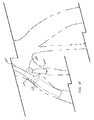
- FIGS. 3-6 illustrate exemplary method steps for deploying the prosthesis 100 at a bifurcation of a common iliac artery 410 into an external iliac artery 412 and an internal iliac artery 414.
- the prosthesis 100 is described herein as being configured for placement in the iliac arteries, this disclosure is not so limited.
- the prosthesis may be configured for placement at any other bifurcation or branch within any other body vessel.
- the prosthesis may be configured for placement at a bifurcation such as the aortic bifurcation; at a branch such as the renal arteries, the celiac artery, the superior mesenteric artery, the innominate artery, the carotid artery, or the subclavian artery; or any other bifurcation or branch at which multiple body vessels are joined to one another.
- a bifurcation such as the aortic bifurcation
- a branch such as the renal arteries, the celiac artery, the superior mesenteric artery, the innominate artery, the carotid artery, or the subclavian artery; or any other bifurcation or branch at which multiple body vessels are joined to one another.
- the prosthesis 100 may be delivered to the common iliac artery 410 using any suitable delivery device or introducer known in the art.
- the prosthesis 100 may be compressed into a reduced diameter delivery configuration and loaded onto the introducer.
- the proximal tip of the introducer may be advanced proximally over a guide wire through a femoral artery and into the common iliac artery 410.
- the prosthesis 100 may be deployed (e.g., by withdrawing a sheath and/or by manipulating one or more trigger wires of the introducer).
- the prosthesis 100 may expand from the delivery configuration to an expanded configuration to engage inner walls of the common iliac artery 410 and the external iliac artery 412 as shown in FIG. 3 .
- the main body 110 of the prosthesis 100 may be positioned within the common iliac artery 410 and the external iliac artery 412.
- the branch 130 of the prosthesis 100 may extend toward the internal iliac artery 414.
- FIGS. 3-6 show a space remaining between the prosthesis 100 and the inner walls of the body vessels.
- the prosthesis 100 may be sized such that, upon deployment, the prosthesis engages the inner walls of the body vessels.
- the branch 130 may include a support structure as described above.
- the support structure may aid in maintaining the lumen of the branch 130 (e.g., the lumen 138, the lumen 148, and/or the lumen 158) open to enable the body fluid to flow through the branch.
- the retrograde branch segment 142 may be positioned between the inner wall of the internal iliac artery 414 and the main body 110 of the prosthesis 100 as shown in FIG. 3 .
- the retrograde branch segment 142 may include a support structure to prevent the retrograde branch segment from being collapsed (e.g., by the radially outward force of the main body 110).
- a second introducer may be used to cannulate the branch 130 of the prosthesis 100 as shown in FIG. 4 .
- the second introducer may be advanced to a second common iliac artery (e.g., through a second femoral artery), over an aortic bifurcation, and into the lumen 113 of the prosthesis 100 through the proximal end 111.
- the second introducer may be advanced into the branch junction 132 via the proximal fenestration 124 and the first end opening 136.
- the second introducer may be further advanced out of the branch 130 via the antegrade branch segment 154 and into the internal iliac artery 414 as shown in FIG. 4 .
- the branch junction 132 and the antegrade branch segment 152 may provide a substantially non-tortuous pathway from the proximal fenestration 124 to the second end opening 158 of the antegrade branch segment to aid in cannulating the branch 130 with the second introducer.
- the branch extension prosthesis 200 may be deployed within the branch 130 and the internal iliac artery 414 using the second introducer.
- the branch extension prosthesis 200 may extend from the antegrade branch segment 152 into the internal iliac artery 414 to couple the prosthesis 100 to the internal iliac artery as shown in FIG. 5 .
- the main extension prosthesis 300 may be delivered and deployed within the main body 110 of the prosthesis 100 as shown in FIG. 6 .
- the main extension prosthesis 300 may be compressed into a reduced diameter delivery configuration and loaded onto a third introducer.
- the third introducer may be advanced into the aorta to a position proximal of the common iliac artery 410. With the third introducer in position, the main extension prosthesis 300 may be deployed (e.g., by withdrawing a sheath and/or by manipulating one or more trigger wires of the introducer).
- the main extension prosthesis 300 may have any suitable configuration known in the art.
- the main extension prosthesis 300 may be configured as a bifurcated prosthesis as shown in FIG. 6 .
- the main body of the main extension prosthesis 300 may be positioned within the aorta, and the legs of the main extension prosthesis may be positioned within each of the common iliac arteries. In this manner, the main extension prosthesis 300 may span the aortic bifurcation as shown in FIG. 6 .
- the main extension prosthesis may have a non-bifurcated configuration.
- the common iliac artery 410 may be relatively short compared to a typical common iliac artery.
- one leg of the main extension prosthesis 300 may extend distally to the bifurcation of the common iliac artery 410 as shown in FIG. 6 .
- Mating a conventional branched prosthesis with the main extension prosthesis in such a situation will result in either the supply point of the branch being blocked by the main extension prosthesis or the branch being positioned distal of the bifurcation. In either case, the conventional branch prosthesis will not fit properly in the space available.
- the prosthesis 100 may have a relatively short proximal neck length L as described above with reference to FIG. 2 . Additionally, or alternatively, the proximal portion 118 of the prosthesis 100 may extend distally beyond the branch point, and the supply point of the prosthesis 100 may be positioned distal of the proximal portion also as described above with reference to FIG. 2 . In this manner, the prosthesis 100 may be capable of mating with the main extension prosthesis 300 with the branch 130 properly aligned with the internal iliac artery 414 and without blocking the supply point as shown in FIG. 6 . In this manner, the prosthesis 100 may be configured for use in patients having relatively short common iliac arteries.
- FIG. 7 illustrates one example of an endoluminal prosthesis 500.
- FIGS. 8 and 9 illustrate transverse cross sectional views of the prosthesis 500 taken along lines 8-8 and 9-9, respectively, of FIG. 7 .
- the prosthesis 500 may be configured substantially as described above with reference to the prosthesis 100 except for the differences described below.
- the prosthesis 500 may include a main body 510 and a branch 530 attached to the main body.
- the main body 510 may have a proximal end opening at a proximal end 511, a distal end opening at a distal end 512, and a main lumen 513 extending longitudinally within the main body.
- the main body 510 may be configured as a tubular graft body including a sidewall 514 and a support structure (not shown) attached to the sidewall 514.
- the prosthesis 500 may include a proximal portion 518 positioned proximal of an intermediate point 522 and a distal portion 520 positioned distal of the intermediate point as shown in FIG. 7 .
- the proximal portion 518 may be configured to engage an extension prosthesis (e.g., the main extension prosthesis 300) as described above with reference to the prosthesis 100.
- the main body 510 may include a proximal fenestration 524 in the sidewall 514 and a distal fenestration 526 in the sidewall.
- the proximal fenestration 524 may be disposed in the proximal portion 518, and the distal fenestration 526 may be disposed in the distal portion 520 as described above with reference to the prosthesis 100.
- the branch 530 may include a branch junction 532, a retrograde branch segment 542, and an antegrade branch segment 552.
- the branch junction 532 may be configured as a tubular graft body including a sidewall 534 of a biocompatible graft material.
- the branch junction 532 may include a first end opening 536 at a first end of the branch junction, a second end opening 537 at a second end of the branch junction, and a lumen 538 extending longitudinally within the branch junction.
- the first end opening 536 may be fluidly coupled to the second end opening 547 of the retrograde branch segment 542 as shown in FIG. 7 .
- the first end opening 536 may be configured as an inlet opening to enable the body fluid to flow from the retrograde branch segment 142 into the branch junction 532.
- the second end opening 537 may be fluidly coupled to the first end opening 556 of the antegrade branch segment 552 as shown in FIG. 7 .
- the second end opening 537 may be configured as an outlet opening to enable the body fluid to flow from the branch junction 532 into the antegrade branch segment 552.
- the branch junction 532 may include a fenestration 540 in the sidewall 534.
- the fenestration 540 may be fluidly coupled to the proximal fenestration 524 of the main body 510 as shown in FIGS. 7-8 . In this manner, the fenestration 540 may be configured as a cannulation opening to enable cannulation of the branch 530 through the proximal fenestration 524 of the main body 510.
- the retrograde branch segment 542 may be configured as a tubular graft body including a sidewall 544 of a biocompatible graft material.
- the retrograde branch segment 542 may include a first end opening 546 at a first end of the retrograde branch segment, a second end opening 547 at a second end of the retrograde branch segment, and a lumen 548 extending longitudinally within the retrograde branch segment.
- the first end opening 546 may be fluidly coupled to the distal fenestration 526 of the main body 510.
- the first end opening 546 may be configured as an inlet opening to enable the body fluid to flow from the main body 510 into the retrograde branch segment 542.
- the second end opening 547 may be fluidly coupled to the first end opening 536 of the branch junction 532.
- the second end opening 547 may be configured as an outlet opening to enable the body fluid to flow from the retrograde branch segment 542 into the branch junction 532.
- the retrograde branch segment 542 may extend in a retrograde direction as described
- the antegrade branch segment 552 may be configured as a tubular graft body including a sidewall 554 of a biocompatible graft material.
- the antegrade branch segment 552 may include a first end opening 556 at a first end of the antegrade branch segment, a second end opening 557 at a second end of the antegrade branch segment, and a lumen 558 extending longitudinally within the antegrade branch segment.
- the first end opening 556 may be fluidly coupled to the second end opening 537 of the branch junction 532.
- the first end opening 556 may be configured as an inlet opening to enable the body fluid to flow from the branch junction 532 into the antegrade branch segment 552.
Priority Applications (1)
| Application Number | Priority Date | Filing Date | Title |
|---|---|---|---|
| EP17206173.1A EP3318220B1 (fr) | 2012-12-31 | 2013-12-23 | Prothèse endoluminale |
Applications Claiming Priority (1)
| Application Number | Priority Date | Filing Date | Title |
|---|---|---|---|
| US201261747536P | 2012-12-31 | 2012-12-31 |
Related Child Applications (2)
| Application Number | Title | Priority Date | Filing Date |
|---|---|---|---|
| EP17206173.1A Division EP3318220B1 (fr) | 2012-12-31 | 2013-12-23 | Prothèse endoluminale |
| EP17206173.1A Division-Into EP3318220B1 (fr) | 2012-12-31 | 2013-12-23 | Prothèse endoluminale |
Publications (3)
| Publication Number | Publication Date |
|---|---|
| EP2749249A2 true EP2749249A2 (fr) | 2014-07-02 |
| EP2749249A3 EP2749249A3 (fr) | 2014-10-29 |
| EP2749249B1 EP2749249B1 (fr) | 2018-01-17 |
Family
ID=49911319
Family Applications (2)
| Application Number | Title | Priority Date | Filing Date |
|---|---|---|---|
| EP17206173.1A Active EP3318220B1 (fr) | 2012-12-31 | 2013-12-23 | Prothèse endoluminale |
| EP13199491.5A Active EP2749249B1 (fr) | 2012-12-31 | 2013-12-23 | Prothèse endoluminale |
Family Applications Before (1)
| Application Number | Title | Priority Date | Filing Date |
|---|---|---|---|
| EP17206173.1A Active EP3318220B1 (fr) | 2012-12-31 | 2013-12-23 | Prothèse endoluminale |
Country Status (2)
| Country | Link |
|---|---|
| US (2) | US9861466B2 (fr) |
| EP (2) | EP3318220B1 (fr) |
Cited By (4)
| Publication number | Priority date | Publication date | Assignee | Title |
|---|---|---|---|---|
| WO2018091464A1 (fr) * | 2016-11-15 | 2018-05-24 | Rheinisch-Westfälische Technische Hochschule (Rwth) Aachen | Système d'endoprothèse et son utilisation dans le traitement de maladies anévrismales |
| US9993330B2 (en) | 2013-03-13 | 2018-06-12 | Cook Medical Technologies Llc | Endoluminal prosthesis system |
| EP3470017A1 (fr) * | 2017-07-18 | 2019-04-17 | Cook Medical Technologies LLC | Procédé de fabrication d'un dérivé bidirectionnel interne |
| WO2019075038A1 (fr) * | 2017-10-11 | 2019-04-18 | Aquedeon Medical, Inc. | Systèmes et méthodes de traitement de dissection aortique |
Families Citing this family (4)
| Publication number | Priority date | Publication date | Assignee | Title |
|---|---|---|---|---|
| US9993360B2 (en) * | 2013-01-08 | 2018-06-12 | Endospan Ltd. | Minimization of stent-graft migration during implantation |
| CN113853178A (zh) | 2019-03-20 | 2021-12-28 | Inqb8医疗科技有限责任公司 | 主动脉夹层植入物 |
| US11311397B2 (en) * | 2019-10-23 | 2022-04-26 | Medtronic Vascular, Inc. | Branch stent graft and delivery method for endovascular treatment of the iliac artery aneurysms |
| US11357612B2 (en) * | 2020-07-16 | 2022-06-14 | Medtronic Vascular, Inc. | Stent graft with sacrificial port |
Citations (5)
| Publication number | Priority date | Publication date | Assignee | Title |
|---|---|---|---|---|
| US5824040A (en) * | 1995-12-01 | 1998-10-20 | Medtronic, Inc. | Endoluminal prostheses and therapies for highly variable body lumens |
| US20090043377A1 (en) * | 2003-01-14 | 2009-02-12 | The Cleveland Clinic Foundation | Branched Vessel Endoluminal Device |
| US20090125100A1 (en) * | 2007-11-13 | 2009-05-14 | Cook Incorporated | Intraluminal Bypass Prosthesis and Prosthesis Delivery and Deployment Kit |
| WO2010024879A1 (fr) * | 2008-08-26 | 2010-03-04 | William A. Cook Australia Pty. Ltd. | Prothèse endovasculaire thoracique de l'aorte dotée d'une zone d'accès |
| US20130018297A1 (en) * | 2011-07-13 | 2013-01-17 | Khoury Michael D | Distal perfusion sheath |
Family Cites Families (14)
| Publication number | Priority date | Publication date | Assignee | Title |
|---|---|---|---|---|
| US4902508A (en) | 1988-07-11 | 1990-02-20 | Purdue Research Foundation | Tissue graft composition |
| US5387235A (en) | 1991-10-25 | 1995-02-07 | Cook Incorporated | Expandable transluminal graft prosthesis for repair of aneurysm |
| US5653743A (en) | 1994-09-09 | 1997-08-05 | Martin; Eric C. | Hypogastric artery bifurcation graft and method of implantation |
| US5554389A (en) | 1995-04-07 | 1996-09-10 | Purdue Research Foundation | Urinary bladder submucosa derived tissue graft |
| US6206931B1 (en) | 1996-08-23 | 2001-03-27 | Cook Incorporated | Graft prosthesis materials |
| US6099567A (en) | 1996-12-10 | 2000-08-08 | Purdue Research Foundation | Stomach submucosa derived tissue graft |
| US5993844A (en) | 1997-05-08 | 1999-11-30 | Organogenesis, Inc. | Chemical treatment, without detergents or enzymes, of tissue to form an acellular, collagenous matrix |
| US6224609B1 (en) | 1998-03-16 | 2001-05-01 | Teramed Inc. | Bifurcated prosthetic graft |
| US7407509B2 (en) | 2003-01-14 | 2008-08-05 | The Cleveland Clinic Foundation | Branched vessel endoluminal device with fenestration |
| AU2006252495B2 (en) | 2005-06-01 | 2011-07-07 | Cook Incorporated | Side branch stent graft |
| US9358097B2 (en) | 2006-03-29 | 2016-06-07 | The Cleveland Clinic Foundation | Iliac leg extension stent graft |
| CA2649705C (fr) | 2006-04-19 | 2015-12-01 | William A. Cook Australia Pty. Ltd | Greffon de stent bifurque double |
| US20090171451A1 (en) | 2007-12-27 | 2009-07-02 | Cook Incorporated | Implantable device having composite weave |
| EP3583916B1 (fr) * | 2011-04-28 | 2023-12-06 | Cook Medical Technologies LLC | Appareil destiné à faciliter le déploiement d'une prothèse endoluminale |
-
2013
- 2013-12-20 US US14/136,631 patent/US9861466B2/en active Active
- 2013-12-23 EP EP17206173.1A patent/EP3318220B1/fr active Active
- 2013-12-23 EP EP13199491.5A patent/EP2749249B1/fr active Active
-
2017
- 2017-11-29 US US15/826,077 patent/US10595982B2/en active Active
Patent Citations (5)
| Publication number | Priority date | Publication date | Assignee | Title |
|---|---|---|---|---|
| US5824040A (en) * | 1995-12-01 | 1998-10-20 | Medtronic, Inc. | Endoluminal prostheses and therapies for highly variable body lumens |
| US20090043377A1 (en) * | 2003-01-14 | 2009-02-12 | The Cleveland Clinic Foundation | Branched Vessel Endoluminal Device |
| US20090125100A1 (en) * | 2007-11-13 | 2009-05-14 | Cook Incorporated | Intraluminal Bypass Prosthesis and Prosthesis Delivery and Deployment Kit |
| WO2010024879A1 (fr) * | 2008-08-26 | 2010-03-04 | William A. Cook Australia Pty. Ltd. | Prothèse endovasculaire thoracique de l'aorte dotée d'une zone d'accès |
| US20130018297A1 (en) * | 2011-07-13 | 2013-01-17 | Khoury Michael D | Distal perfusion sheath |
Cited By (7)
| Publication number | Priority date | Publication date | Assignee | Title |
|---|---|---|---|---|
| US9993330B2 (en) | 2013-03-13 | 2018-06-12 | Cook Medical Technologies Llc | Endoluminal prosthesis system |
| EP2777610B1 (fr) * | 2013-03-13 | 2019-05-22 | Cook Medical Technologies LLC | Système de prothèse endoluminale |
| WO2018091464A1 (fr) * | 2016-11-15 | 2018-05-24 | Rheinisch-Westfälische Technische Hochschule (Rwth) Aachen | Système d'endoprothèse et son utilisation dans le traitement de maladies anévrismales |
| EP3470017A1 (fr) * | 2017-07-18 | 2019-04-17 | Cook Medical Technologies LLC | Procédé de fabrication d'un dérivé bidirectionnel interne |
| US10660770B2 (en) | 2017-07-18 | 2020-05-26 | Cook Medical Technologies Llc | Method of making an internal bidirectional branch |
| US11534318B2 (en) | 2017-07-18 | 2022-12-27 | Cook Medical Technologies Llc | Stent graft having an internal bidirectional branch |
| WO2019075038A1 (fr) * | 2017-10-11 | 2019-04-18 | Aquedeon Medical, Inc. | Systèmes et méthodes de traitement de dissection aortique |
Also Published As
| Publication number | Publication date |
|---|---|
| US20140188207A1 (en) | 2014-07-03 |
| EP3318220B1 (fr) | 2019-08-07 |
| US9861466B2 (en) | 2018-01-09 |
| EP3318220A1 (fr) | 2018-05-09 |
| US10595982B2 (en) | 2020-03-24 |
| EP2749249B1 (fr) | 2018-01-17 |
| EP2749249A3 (fr) | 2014-10-29 |
| US20180078359A1 (en) | 2018-03-22 |
Similar Documents
| Publication | Publication Date | Title |
|---|---|---|
| US10595982B2 (en) | Endoluminal prosthesis | |
| US8257430B2 (en) | Interconnected leg extensions for an endoluminal prosthesis | |
| US7674284B2 (en) | Endoluminal graft | |
| EP2007313B1 (fr) | Greffon de stent | |
| US8945205B2 (en) | Branch vessel prostheses | |
| EP3141215B1 (fr) | Dispositif endoluminal pour vaisseaux ramifiés | |
| US7615072B2 (en) | Endoluminal prosthesis | |
| US9993330B2 (en) | Endoluminal prosthesis system | |
| EP1441782B1 (fr) | Prothèse endoluminale interconnectable | |
| US20050149166A1 (en) | Branch vessel prosthesis with anchoring device and method | |
| EP2837362A1 (fr) | Ensemble pour le traitement de vaisseaux ramifiés | |
| EP2702960B1 (fr) | Prothèse endoluminale et dispositif d'administration | |
| AU2018214103B1 (en) | A stent-graft | |
| US10709543B2 (en) | Non-cylindrical mesh top stent with twisted sections | |
| US10149777B2 (en) | Orientation marker on pusher for deployment of endoluminal prostheses |
Legal Events
| Date | Code | Title | Description |
|---|---|---|---|
| 17P | Request for examination filed |
Effective date: 20131223 |
|
| AK | Designated contracting states |
Kind code of ref document: A2 Designated state(s): AL AT BE BG CH CY CZ DE DK EE ES FI FR GB GR HR HU IE IS IT LI LT LU LV MC MK MT NL NO PL PT RO RS SE SI SK SM TR |
|
| AX | Request for extension of the european patent |
Extension state: BA ME |
|
| PUAI | Public reference made under article 153(3) epc to a published international application that has entered the european phase |
Free format text: ORIGINAL CODE: 0009012 |
|
| PUAL | Search report despatched |
Free format text: ORIGINAL CODE: 0009013 |
|
| AK | Designated contracting states |
Kind code of ref document: A3 Designated state(s): AL AT BE BG CH CY CZ DE DK EE ES FI FR GB GR HR HU IE IS IT LI LT LU LV MC MK MT NL NO PL PT RO RS SE SI SK SM TR |
|
| AX | Request for extension of the european patent |
Extension state: BA ME |
|
| RIC1 | Information provided on ipc code assigned before grant |
Ipc: A61F 2/07 20130101AFI20140919BHEP |
|
| R17P | Request for examination filed (corrected) |
Effective date: 20150429 |
|
| RBV | Designated contracting states (corrected) |
Designated state(s): AL AT BE BG CH CY CZ DE DK EE ES FI FR GB GR HR HU IE IS IT LI LT LU LV MC MK MT NL NO PL PT RO RS SE SI SK SM TR |
|
| 17Q | First examination report despatched |
Effective date: 20160803 |
|
| STAA | Information on the status of an ep patent application or granted ep patent |
Free format text: STATUS: EXAMINATION IS IN PROGRESS |
|
| GRAP | Despatch of communication of intention to grant a patent |
Free format text: ORIGINAL CODE: EPIDOSNIGR1 |
|
| STAA | Information on the status of an ep patent application or granted ep patent |
Free format text: STATUS: GRANT OF PATENT IS INTENDED |
|
| INTG | Intention to grant announced |
Effective date: 20170720 |
|
| GRAS | Grant fee paid |
Free format text: ORIGINAL CODE: EPIDOSNIGR3 |
|
| GRAA | (expected) grant |
Free format text: ORIGINAL CODE: 0009210 |
|
| STAA | Information on the status of an ep patent application or granted ep patent |
Free format text: STATUS: THE PATENT HAS BEEN GRANTED |
|
| AK | Designated contracting states |
Kind code of ref document: B1 Designated state(s): AL AT BE BG CH CY CZ DE DK EE ES FI FR GB GR HR HU IE IS IT LI LT LU LV MC MK MT NL NO PL PT RO RS SE SI SK SM TR |
|
| REG | Reference to a national code |
Ref country code: GB Ref legal event code: FG4D |
|
| REG | Reference to a national code |
Ref country code: CH Ref legal event code: EP |
|
| REG | Reference to a national code |
Ref country code: IE Ref legal event code: FG4D |
|
| RIN2 | Information on inventor provided after grant (corrected) |
Inventor name: HAVEL, WILLIAM JOHN Inventor name: HUSER, MATTHEW S. |
|
| REG | Reference to a national code |
Ref country code: AT Ref legal event code: REF Ref document number: 963884 Country of ref document: AT Kind code of ref document: T Effective date: 20180215 |
|
| REG | Reference to a national code |
Ref country code: DE Ref legal event code: R096 Ref document number: 602013032306 Country of ref document: DE |
|
| REG | Reference to a national code |
Ref country code: NL Ref legal event code: MP Effective date: 20180117 |
|
| REG | Reference to a national code |
Ref country code: LT Ref legal event code: MG4D |
|
| REG | Reference to a national code |
Ref country code: AT Ref legal event code: MK05 Ref document number: 963884 Country of ref document: AT Kind code of ref document: T Effective date: 20180117 |
|
| PG25 | Lapsed in a contracting state [announced via postgrant information from national office to epo] |
Ref country code: NL Free format text: LAPSE BECAUSE OF FAILURE TO SUBMIT A TRANSLATION OF THE DESCRIPTION OR TO PAY THE FEE WITHIN THE PRESCRIBED TIME-LIMIT Effective date: 20180117 |
|
| PG25 | Lapsed in a contracting state [announced via postgrant information from national office to epo] |
Ref country code: LT Free format text: LAPSE BECAUSE OF FAILURE TO SUBMIT A TRANSLATION OF THE DESCRIPTION OR TO PAY THE FEE WITHIN THE PRESCRIBED TIME-LIMIT Effective date: 20180117 Ref country code: CY Free format text: LAPSE BECAUSE OF FAILURE TO SUBMIT A TRANSLATION OF THE DESCRIPTION OR TO PAY THE FEE WITHIN THE PRESCRIBED TIME-LIMIT Effective date: 20180117 Ref country code: FI Free format text: LAPSE BECAUSE OF FAILURE TO SUBMIT A TRANSLATION OF THE DESCRIPTION OR TO PAY THE FEE WITHIN THE PRESCRIBED TIME-LIMIT Effective date: 20180117 Ref country code: NO Free format text: LAPSE BECAUSE OF FAILURE TO SUBMIT A TRANSLATION OF THE DESCRIPTION OR TO PAY THE FEE WITHIN THE PRESCRIBED TIME-LIMIT Effective date: 20180417 Ref country code: ES Free format text: LAPSE BECAUSE OF FAILURE TO SUBMIT A TRANSLATION OF THE DESCRIPTION OR TO PAY THE FEE WITHIN THE PRESCRIBED TIME-LIMIT Effective date: 20180117 Ref country code: HR Free format text: LAPSE BECAUSE OF FAILURE TO SUBMIT A TRANSLATION OF THE DESCRIPTION OR TO PAY THE FEE WITHIN THE PRESCRIBED TIME-LIMIT Effective date: 20180117 |
|
| PG25 | Lapsed in a contracting state [announced via postgrant information from national office to epo] |
Ref country code: IS Free format text: LAPSE BECAUSE OF FAILURE TO SUBMIT A TRANSLATION OF THE DESCRIPTION OR TO PAY THE FEE WITHIN THE PRESCRIBED TIME-LIMIT Effective date: 20180517 Ref country code: BG Free format text: LAPSE BECAUSE OF FAILURE TO SUBMIT A TRANSLATION OF THE DESCRIPTION OR TO PAY THE FEE WITHIN THE PRESCRIBED TIME-LIMIT Effective date: 20180417 Ref country code: AT Free format text: LAPSE BECAUSE OF FAILURE TO SUBMIT A TRANSLATION OF THE DESCRIPTION OR TO PAY THE FEE WITHIN THE PRESCRIBED TIME-LIMIT Effective date: 20180117 Ref country code: PL Free format text: LAPSE BECAUSE OF FAILURE TO SUBMIT A TRANSLATION OF THE DESCRIPTION OR TO PAY THE FEE WITHIN THE PRESCRIBED TIME-LIMIT Effective date: 20180117 Ref country code: RS Free format text: LAPSE BECAUSE OF FAILURE TO SUBMIT A TRANSLATION OF THE DESCRIPTION OR TO PAY THE FEE WITHIN THE PRESCRIBED TIME-LIMIT Effective date: 20180117 Ref country code: SE Free format text: LAPSE BECAUSE OF FAILURE TO SUBMIT A TRANSLATION OF THE DESCRIPTION OR TO PAY THE FEE WITHIN THE PRESCRIBED TIME-LIMIT Effective date: 20180117 Ref country code: LV Free format text: LAPSE BECAUSE OF FAILURE TO SUBMIT A TRANSLATION OF THE DESCRIPTION OR TO PAY THE FEE WITHIN THE PRESCRIBED TIME-LIMIT Effective date: 20180117 Ref country code: GR Free format text: LAPSE BECAUSE OF FAILURE TO SUBMIT A TRANSLATION OF THE DESCRIPTION OR TO PAY THE FEE WITHIN THE PRESCRIBED TIME-LIMIT Effective date: 20180418 |
|
| REG | Reference to a national code |
Ref country code: DE Ref legal event code: R097 Ref document number: 602013032306 Country of ref document: DE |
|
| PG25 | Lapsed in a contracting state [announced via postgrant information from national office to epo] |
Ref country code: IT Free format text: LAPSE BECAUSE OF FAILURE TO SUBMIT A TRANSLATION OF THE DESCRIPTION OR TO PAY THE FEE WITHIN THE PRESCRIBED TIME-LIMIT Effective date: 20180117 Ref country code: EE Free format text: LAPSE BECAUSE OF FAILURE TO SUBMIT A TRANSLATION OF THE DESCRIPTION OR TO PAY THE FEE WITHIN THE PRESCRIBED TIME-LIMIT Effective date: 20180117 Ref country code: RO Free format text: LAPSE BECAUSE OF FAILURE TO SUBMIT A TRANSLATION OF THE DESCRIPTION OR TO PAY THE FEE WITHIN THE PRESCRIBED TIME-LIMIT Effective date: 20180117 Ref country code: AL Free format text: LAPSE BECAUSE OF FAILURE TO SUBMIT A TRANSLATION OF THE DESCRIPTION OR TO PAY THE FEE WITHIN THE PRESCRIBED TIME-LIMIT Effective date: 20180117 |
|
| PLBE | No opposition filed within time limit |
Free format text: ORIGINAL CODE: 0009261 |
|
| STAA | Information on the status of an ep patent application or granted ep patent |
Free format text: STATUS: NO OPPOSITION FILED WITHIN TIME LIMIT |
|
| PG25 | Lapsed in a contracting state [announced via postgrant information from national office to epo] |
Ref country code: DK Free format text: LAPSE BECAUSE OF FAILURE TO SUBMIT A TRANSLATION OF THE DESCRIPTION OR TO PAY THE FEE WITHIN THE PRESCRIBED TIME-LIMIT Effective date: 20180117 Ref country code: SK Free format text: LAPSE BECAUSE OF FAILURE TO SUBMIT A TRANSLATION OF THE DESCRIPTION OR TO PAY THE FEE WITHIN THE PRESCRIBED TIME-LIMIT Effective date: 20180117 Ref country code: SM Free format text: LAPSE BECAUSE OF FAILURE TO SUBMIT A TRANSLATION OF THE DESCRIPTION OR TO PAY THE FEE WITHIN THE PRESCRIBED TIME-LIMIT Effective date: 20180117 Ref country code: CZ Free format text: LAPSE BECAUSE OF FAILURE TO SUBMIT A TRANSLATION OF THE DESCRIPTION OR TO PAY THE FEE WITHIN THE PRESCRIBED TIME-LIMIT Effective date: 20180117 |
|
| 26N | No opposition filed |
Effective date: 20181018 |
|
| PG25 | Lapsed in a contracting state [announced via postgrant information from national office to epo] |
Ref country code: SI Free format text: LAPSE BECAUSE OF FAILURE TO SUBMIT A TRANSLATION OF THE DESCRIPTION OR TO PAY THE FEE WITHIN THE PRESCRIBED TIME-LIMIT Effective date: 20180117 |
|
| REG | Reference to a national code |
Ref country code: CH Ref legal event code: PL |
|
| PG25 | Lapsed in a contracting state [announced via postgrant information from national office to epo] |
Ref country code: LU Free format text: LAPSE BECAUSE OF NON-PAYMENT OF DUE FEES Effective date: 20181223 Ref country code: MC Free format text: LAPSE BECAUSE OF FAILURE TO SUBMIT A TRANSLATION OF THE DESCRIPTION OR TO PAY THE FEE WITHIN THE PRESCRIBED TIME-LIMIT Effective date: 20180117 |
|
| REG | Reference to a national code |
Ref country code: BE Ref legal event code: MM Effective date: 20181231 |
|
| PG25 | Lapsed in a contracting state [announced via postgrant information from national office to epo] |
Ref country code: FR Free format text: LAPSE BECAUSE OF NON-PAYMENT OF DUE FEES Effective date: 20181231 |
|
| PG25 | Lapsed in a contracting state [announced via postgrant information from national office to epo] |
Ref country code: BE Free format text: LAPSE BECAUSE OF NON-PAYMENT OF DUE FEES Effective date: 20181231 |
|
| PG25 | Lapsed in a contracting state [announced via postgrant information from national office to epo] |
Ref country code: LI Free format text: LAPSE BECAUSE OF NON-PAYMENT OF DUE FEES Effective date: 20181231 Ref country code: CH Free format text: LAPSE BECAUSE OF NON-PAYMENT OF DUE FEES Effective date: 20181231 |
|
| PG25 | Lapsed in a contracting state [announced via postgrant information from national office to epo] |
Ref country code: MT Free format text: LAPSE BECAUSE OF NON-PAYMENT OF DUE FEES Effective date: 20181223 |
|
| PG25 | Lapsed in a contracting state [announced via postgrant information from national office to epo] |
Ref country code: TR Free format text: LAPSE BECAUSE OF FAILURE TO SUBMIT A TRANSLATION OF THE DESCRIPTION OR TO PAY THE FEE WITHIN THE PRESCRIBED TIME-LIMIT Effective date: 20180117 |
|
| PG25 | Lapsed in a contracting state [announced via postgrant information from national office to epo] |
Ref country code: PT Free format text: LAPSE BECAUSE OF FAILURE TO SUBMIT A TRANSLATION OF THE DESCRIPTION OR TO PAY THE FEE WITHIN THE PRESCRIBED TIME-LIMIT Effective date: 20180117 |
|
| PG25 | Lapsed in a contracting state [announced via postgrant information from national office to epo] |
Ref country code: MK Free format text: LAPSE BECAUSE OF NON-PAYMENT OF DUE FEES Effective date: 20180117 Ref country code: HU Free format text: LAPSE BECAUSE OF FAILURE TO SUBMIT A TRANSLATION OF THE DESCRIPTION OR TO PAY THE FEE WITHIN THE PRESCRIBED TIME-LIMIT; INVALID AB INITIO Effective date: 20131223 |
|
| P01 | Opt-out of the competence of the unified patent court (upc) registered |
Effective date: 20230602 |
|
| PGFP | Annual fee paid to national office [announced via postgrant information from national office to epo] |
Ref country code: GB Payment date: 20231108 Year of fee payment: 11 |
|
| PGFP | Annual fee paid to national office [announced via postgrant information from national office to epo] |
Ref country code: IE Payment date: 20231128 Year of fee payment: 11 Ref country code: DE Payment date: 20231108 Year of fee payment: 11 |