EP2748641B1 - Data-driven optimization of event acceptance/rejection logic - Google Patents
Data-driven optimization of event acceptance/rejection logic Download PDFInfo
- Publication number
- EP2748641B1 EP2748641B1 EP12795064.0A EP12795064A EP2748641B1 EP 2748641 B1 EP2748641 B1 EP 2748641B1 EP 12795064 A EP12795064 A EP 12795064A EP 2748641 B1 EP2748641 B1 EP 2748641B1
- Authority
- EP
- European Patent Office
- Prior art keywords
- energy
- events
- time
- window
- event
- Prior art date
- Legal status (The legal status is an assumption and is not a legal conclusion. Google has not performed a legal analysis and makes no representation as to the accuracy of the status listed.)
- Not-in-force
Links
Images


Classifications
-
- A—HUMAN NECESSITIES
- A61—MEDICAL OR VETERINARY SCIENCE; HYGIENE
- A61B—DIAGNOSIS; SURGERY; IDENTIFICATION
- A61B6/00—Apparatus for radiation diagnosis, e.g. combined with radiation therapy equipment
- A61B6/52—Devices using data or image processing specially adapted for radiation diagnosis
- A61B6/5205—Devices using data or image processing specially adapted for radiation diagnosis involving processing of raw data to produce diagnostic data
-
- G—PHYSICS
- G01—MEASURING; TESTING
- G01T—MEASUREMENT OF NUCLEAR OR X-RADIATION
- G01T1/00—Measuring X-radiation, gamma radiation, corpuscular radiation, or cosmic radiation
- G01T1/29—Measurement performed on radiation beams, e.g. position or section of the beam; Measurement of spatial distribution of radiation
- G01T1/2914—Measurement of spatial distribution of radiation
- G01T1/2985—In depth localisation, e.g. using positron emitters; Tomographic imaging (longitudinal and transverse section imaging; apparatus for radiation diagnosis sequentially in different planes, steroscopic radiation diagnosis)
-
- A—HUMAN NECESSITIES
- A61—MEDICAL OR VETERINARY SCIENCE; HYGIENE
- A61B—DIAGNOSIS; SURGERY; IDENTIFICATION
- A61B6/00—Apparatus for radiation diagnosis, e.g. combined with radiation therapy equipment
- A61B6/02—Devices for diagnosis sequentially in different planes; Stereoscopic radiation diagnosis
- A61B6/03—Computerised tomographs
- A61B6/037—Emission tomography
-
- A—HUMAN NECESSITIES
- A61—MEDICAL OR VETERINARY SCIENCE; HYGIENE
- A61B—DIAGNOSIS; SURGERY; IDENTIFICATION
- A61B6/00—Apparatus for radiation diagnosis, e.g. combined with radiation therapy equipment
- A61B6/04—Positioning of patients; Tiltable beds or the like
- A61B6/0407—Supports, e.g. tables or beds, for the body or parts of the body
-
- A—HUMAN NECESSITIES
- A61—MEDICAL OR VETERINARY SCIENCE; HYGIENE
- A61B—DIAGNOSIS; SURGERY; IDENTIFICATION
- A61B6/00—Apparatus for radiation diagnosis, e.g. combined with radiation therapy equipment
- A61B6/46—Apparatus for radiation diagnosis, e.g. combined with radiation therapy equipment with special arrangements for interfacing with the operator or the patient
- A61B6/467—Apparatus for radiation diagnosis, e.g. combined with radiation therapy equipment with special arrangements for interfacing with the operator or the patient characterised by special input means
- A61B6/469—Apparatus for radiation diagnosis, e.g. combined with radiation therapy equipment with special arrangements for interfacing with the operator or the patient characterised by special input means for selecting a region of interest [ROI]
-
- A—HUMAN NECESSITIES
- A61—MEDICAL OR VETERINARY SCIENCE; HYGIENE
- A61B—DIAGNOSIS; SURGERY; IDENTIFICATION
- A61B6/00—Apparatus for radiation diagnosis, e.g. combined with radiation therapy equipment
- A61B6/48—Diagnostic techniques
- A61B6/481—Diagnostic techniques involving the use of contrast agents
-
- A—HUMAN NECESSITIES
- A61—MEDICAL OR VETERINARY SCIENCE; HYGIENE
- A61B—DIAGNOSIS; SURGERY; IDENTIFICATION
- A61B6/00—Apparatus for radiation diagnosis, e.g. combined with radiation therapy equipment
- A61B6/52—Devices using data or image processing specially adapted for radiation diagnosis
- A61B6/5294—Devices using data or image processing specially adapted for radiation diagnosis involving using additional data, e.g. patient information, image labeling, acquisition parameters
-
- A—HUMAN NECESSITIES
- A61—MEDICAL OR VETERINARY SCIENCE; HYGIENE
- A61B—DIAGNOSIS; SURGERY; IDENTIFICATION
- A61B6/00—Apparatus for radiation diagnosis, e.g. combined with radiation therapy equipment
- A61B6/54—Control of apparatus or devices for radiation diagnosis
- A61B6/542—Control of apparatus or devices for radiation diagnosis involving control of exposure
- A61B6/544—Control of apparatus or devices for radiation diagnosis involving control of exposure dependent on patient size
-
- A—HUMAN NECESSITIES
- A61—MEDICAL OR VETERINARY SCIENCE; HYGIENE
- A61B—DIAGNOSIS; SURGERY; IDENTIFICATION
- A61B6/00—Apparatus for radiation diagnosis, e.g. combined with radiation therapy equipment
- A61B6/54—Control of apparatus or devices for radiation diagnosis
- A61B6/547—Control of apparatus or devices for radiation diagnosis involving tracking of position of the device or parts of the device
-
- A—HUMAN NECESSITIES
- A61—MEDICAL OR VETERINARY SCIENCE; HYGIENE
- A61K—PREPARATIONS FOR MEDICAL, DENTAL OR TOILETRY PURPOSES
- A61K51/00—Preparations containing radioactive substances for use in therapy or testing in vivo
-
- A—HUMAN NECESSITIES
- A61—MEDICAL OR VETERINARY SCIENCE; HYGIENE
- A61K—PREPARATIONS FOR MEDICAL, DENTAL OR TOILETRY PURPOSES
- A61K2121/00—Preparations for use in therapy
-
- A—HUMAN NECESSITIES
- A61—MEDICAL OR VETERINARY SCIENCE; HYGIENE
- A61K—PREPARATIONS FOR MEDICAL, DENTAL OR TOILETRY PURPOSES
- A61K2123/00—Preparations for testing in vivo
Definitions
- the present application relates to Nuclear medicine imaging, Positron Emission Tomography (PET), Single Photon Emission Computed Tomography (SPECT), and specifically to determination of events used to reconstruct PET images.
- PET Positron Emission Tomography
- SPECT Single Photon Emission Computed Tomography
- PET nuclear medicine involves the introduction of a radiopharmaceutical in the body of a subject.
- the radiopharmaceuticals target specific areas of interest or organs through metabolic processes.
- the radiopharmaceuticals decay with a relatively short half-life.
- the base process for image formation are decay events that result in a positron being emitted.
- the positron travels a short distance before striking an electron.
- an annihilation event occurs.
- An annihilation event is marked by the emission of two gamma photons of energy at 511 keV which travel in 180° opposite directions.
- the path traveled by photons in opposite directions is called the line-of-response (LOR).
- LOR line-of-response
- a PET scanner detects the pairs of gamma photons from a common annihilation event which are called coincidence events.
- a PET scanner discriminates between the coincidence events and scattered or random events.
- a scattered event is an event in which the path of a photon is altered, typically due to Compton scattering by a dense material. The probability of scattering varies with the patient size, density of various types of tissue such as bone, and other objects present such as implants.
- the photon loses energy and arrives with less than 511 keV in energy.
- the angle of scattering is proportional to the lost energy. The larger the energy window, the greater the Compton scattering angle that is permitted.
- a random event occurs when only one of a pair of photons strikes a detector.
- the other photon either travels outside the area covered by the detectors or is entirely absorbed by interaction with a nucleus or the like.
- a single random event is not used because both events of a pair are needed to calculate the LOR used in the reconstruction algorithm.
- the time interval for a gamma photon to travel from one detector to a diametrically opposing detector represents the maximum interval between coincidence events.
- time interval for acceptable coincidence events cannot be set arbitrarily small.
- the time interval includes both the travel time and delays or differences in measuring time. As imprecision in time measurement is reduced, time of flight measurements can be made and become more accurate. However, time differences between individual detector measurements, precise time measurement, and variations due to operating conditions still contribute to the imprecision of event times. Larger time windows or longer acceptable intervals between events which are coincident allow for greater imprecision in the detected LORs.
- the difference of a measured energy level of an event and the expected energy 511 keV of a gamma photon emitted from an annihilation event cannot be arbitrarily small.
- Particular technologies used in detectors, operating temperatures, and other imprecision combine to vary the measured energy level of an event.
- the number of detected coincidence events varies with the number of annihilation events occurring.
- the number of annihilation events is determined by the type of radiopharmaceutical used, and the concentration of the radiopharmaceutical in the detection region.
- the type of radionuclide in the radiopharmaceutical has a known half-life or decay rate. As the radionuclides decay, the concentration of the radiopharmaceutical decreases as does the count rate.
- the radiopharmaceutical is configured to target selected metabolic processes which uptake or absorb the radiopharmaceutical to create concentrated areas or bright spots in the image.
- the radiopharmaceutical washes out of target areas or target organs at different rates as the radionuclide decays, the pharmaceutical is metabolized or the like.
- the concentration of a radiopharmaceutical affects the emission rate. For example, Rubidium-82 chloride targets cardiac muscle cells. It has a high emission rate and a short half life of 75 seconds.
- Discrimination of events can be greater with very high emission rates while still recording enough coincidence events to reconstruct quality images. Alternatively discrimination of events can be lessened with lower emission rates in order to obtain more coincidence events.
- a statistical method uses a small sample set before computing a center or distribution.
- Hardware parameters for determining a coincidence event are typically set by the manufacturer, and are not accessible for modification by an operator. Two parameters are set: a time window which determines the maximum permitted interval between events for coincidence, and the minimum energy level required for a straight, non-scattered LOR event.
- sensitivity to true events and false acceptance of spurious events include strikes of photons at detectors which are not pairs emitted from the same annihilation event and include random and scattered events.
- the present application provides a new and improved data-driven acceptance of coincidence events which overcomes the above-referenced problems and others.
- a method of nuclear medicine imaging according to claim 11 is provided.
- a nuclear medicine imaging system according to claim 1 is provided.
- One advantage is that time and/or energy windows for acceptance of coincidence events can be adjusted with known data prior to data acquisition.
- Another advantage is that time and/or energy windows for acceptance of coincidence events can be dynamically adjusted during data acquisition based on feedback.
- Another advantage is that the number of coincidence events recorded is increased.
- Another advantage is the improvement in image quality of PET images due to the improvement in data quality used to reconstruct images.
- Another improvement is the recording of event information used to analyze errors.
- the invention may take form in various components and arrangements of components, and in various steps and arrangements of steps.
- the drawings are only for purposes of illustrating the preferred embodiments and are not to be construed as limiting the invention.
- a PET scanner 10 detects positron emission events.
- a location of an annihilation event 15 occurs within a subject, targeted organ, or region of interest 20 .
- the subject is placed on an exam table 30 which moves through a detector array 40 .
- the detector array 40 is typically shaped as a ring inside the gantry 30 with rows of detectors 60 extending longitudinally.
- the detectors 60 receive gamma photons and transmit pulses of electricity on wiring circuits 70 when a gamma photon strikes.
- An example of a detector is a scintillator crystal connected to a photomultiplier tube, a photodiode, a silicon photomultiplier (SiPM), or the like.
- the amplitude of the pulse reflects the energy of the photon received.
- a clock circuit adds a time stamp, and a detector circuit adds an identification or location of the detecting detector to form a digital data packet for each detected event.
- the wiring circuits 70 connect the individual detectors to a coincidence processing unit 80 .
- the coincidence processing unit 80 retrieves from memory 100 the time and energy window settings as a function of time and/or table 30 position to be used during data acquisition.
- the settings are stored in a memory 100 with a system matrix file which specifies the operating environment for the system.
- the coincidence processing unit 80 receives event data and places the event data in a temporary memory such as a buffer 85 .
- the coincidence processing unit uses the time and energy window settings in effect for that table position to determine whether pairs of events comprise a coincidence event. If a pair of events meets the energy and time window settings, the pair is accepted as a coincidence pair.
- a coincidence pair defines a LOR 25 between the detectors which detected the pair of events.
- the coincidence processing unit 80 uses the time and energy window settings 100 corresponding to the current table position. Alternatively, an elapse of a time such as the passing of a selected fraction of the half-life, causes a change in window settings.
- the windowing parameters are adjusted dynamically during the data acquisition process based on feedback from the detected data.
- the coincidence processing unit 80 maintains a counter 90 of a current rate at which events are being received. When the count rate is high, windowing parameters are narrowed. When the count rate is low, windowing parameters are widened.
- windowing parameters are adjusted based on current operating temperature, or a shift in the maximum energy of events.
- One or more temperature sensors 95 mounted on the detector array provide additional feedback to the coincidence processing unit 80 .
- the windowing parameters are adjusted based on an amount of scattered or spurious events.
- the event pair is logged to an event list memory 110 .
- the event list memory 110 records the event time, energy level, detection location and changes in window settings.
- the reconstruction processor 140 reads the coincidence event list memory 110 and reconstructs an image.
- the image is displayed on a display 150 or alternatively stored for later access.
- all event pairs are within preselected windows, which removes noise, unacceptable scatter and the like, and are stored in the list memory 110 .
- the reconstruction processor 140 decides which coincident pairs to reconstruct based at least on the time and energies of each event, such that the reconstruction process sets the time and energy during reconstruction.
- the relative detection times of the events of the coincident pair can be used to determine time-of-flight (TOF) information and a TOF reconstruction is performed.
- TOF time-of-flight
- an image can be constructed with initial time and energy windows. Based on characteristics of the image or the like, the image can be reconstructed again using events with meet more restrictive time and/or energy window requirements.
- the patient size is input or selected using an input device 170 and/or stored lists.
- the target organ or region of interest is input or selected.
- Information about the radiopharmaceutical is input or selected such as the type of radiopharmaceutical, the time the radiopharmaceutical was administered to the subject and the dosage administered.
- Information stored with the type of radiopharmaceutical includes half-life, and emission rates.
- An attenuation map (AC map) for the patient is typically, e.g. using computed tomography, generated prior to the PET imaging and used in the PET reconstruction.
- the AC map provides information about the relative densities and expected scatter to be encountered by different regions during data acquisition.
- the processor inputs this information and outputs corresponding time and energy windowing parameters stored.
- the windows are adjusted based on the density of tissue lying along each defined LOR.
- the windows are adjusted to improve the count rate in some regions and LOR accuracy in other regions to optimize sensitivity in some regions of the reconstructed image and resolution in others.
- Random events are determined when the time interval, T between events ⁇ 1 and ⁇ 2 detected is greater than a set time window W T .
- W T time window
- two separate radionuclide decay events must have produced the detected photon events.
- a LOR does not pass through the subject.
- true events the LOR between the detectors passes through the point of emission.
- Scattered events occur due to Compton scattering. The greater the Compton or scatter angle, the greater the energy loss. Scattered events are discriminated by their energy level.
- An event, ⁇ 1 is scattered when the measured energy level is less than a set amount W E,0 , e.g. 511 keV.
- the LOR for a scattered event pair ⁇ 1 , ⁇ 2 is not a straight line through the emission point. However, if the scatter angle is very small, the LOR deviates very little from the straight line through the emission point and can be used with minimal effect on resolution and accuracy. In the diagram solid lines are true paths, while dotted lines represent the false LORs.
- the coincidence processing unit 80 retrieves the time and energy window parameters stored in memory 100 by the processor 140 prior to data acquisition, input by the clinician, or dynamically calculated by the processor.
- This information includes time and energy window parameters by table 30 position and/or time information (e.g. based on half-life), and/or target and radio pharmaceutical characteristics based on inputs from a lookup table 160 .
- the energy window parameter(s) 225 and the time window parameter 260 are dynamically adjusted 105 by the coincidence processor 80 based on feedback from a counter 90 , temperature sensor 95 , etc.
- the energy window 220 sets a minimum energy level 225 permitted of an event to be designated a part of a coincidence pair. Alternatively, the energy window 220 includes both a minimum and a maximum to allow for errors in energy measurement. If the event does not pass the window 220 for the energy level, the event is discarded.
- W E ⁇ E e where W E is the energy window as a function of table position and/or time including dynamic adjustments, and E e is a measured energy level e.
- a maximum value of measured energy W E,max may be used for the energy window, W E,min ⁇ E e ⁇ W E,max , otherwise the maximum of 511 keV is used.
- Events passing the energy window 220 are paired with another event as a coincidence pair.
- the event pairs must pass a time window 270 .
- the time window 270 is a maximum time interval between detected events for the event to be considered coincidence 260 .
- ⁇ W T W T 260 is the time window 270 parameter as a function of table position and/or time including dynamic adjustments, E T1 is a detected event at time T1, and E T2 is a detected event at time T2. If the coincidence pair passes the time window 270 then it is recorded as a coincidence pair in the coincidence event list 110 . If it does not pass the time window then it is discarded.
- a preliminary set of windows determine filtering of spurious events before the events are recorded. All events which pass the preliminary window are stored in list memory 110 . Events which do not pass the preliminary set of windows are screened again for use in error analysis.
- a secondary energy window 240 is employed and if the measured energy of an event 200 exceeds the second window value 230 , the event is logged or recorded as a scatter event. For the scatter event list, W* E ⁇ E e , where W* E is the maximum acceptable window energy and W* E ⁇ W E .
- the detected events are stored in an unfiltered list memory 410 .
- preliminary filtering is performed with a preliminary energy window 425 and a preliminary time window 460 .
- the preliminary energy window keeps events with an energy in a range useable for reconstruction under at least some circumstances, e.g. lowest possible acceptable energy.
- the preliminary time window represents the widest possible time window that might be selected, e.g. 8 nanoseconds. This separates the scattered events and random events from coincident pairs under the most likable definition coincident pairs.
- Bed position, elapsed time since injection of the radiopharmaceutical, temperature, and other information to be used for dynamic windowing are stored in the event list 410 .
- the coincidence processing unit 80 adjusts the window parameters in accordance to table position, and the like as described above, e.g. from the system matrix.
- the restrictively windowed events are stored or buffered in a memory 510 and used by the reconstruction processor to restrict the image.
- the coincidence processor 80 readjusts the energy window 225 , 220 and/or the time window 260 , 270 and repeats the reconstruction.
- the energy window and the time window change with region of the patient.
- LORs that pass through a region of the subject with high count rates can be subject to more restrictive windows and LORS which pass through regions with low count rates can be subject to wider, less restrictive windows.
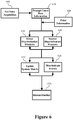
- FIGURE 6 a diagram illustrates an embodiment of PET imaging.
- An occurrence of radiation is detected 600 during data acquisition.
- Count rate information 610 and prior information 620 determined from the acquired data are used to adjust the energy and time windows.
- the energy and time discrimination windows are widened 630 when for example the count rate in a particular region is low.
- the discrimination windows are narrowed 640 when for example count rates in a particular region is high. High count rates use computing resources and do not necessarily further add to the quality of an image.
- Windows are adjusted when the processor determines from the attenuation map that a LOR is likely a scattered event.
- Events are discriminated 660 based on the window settings.
- the system matrix that describes the operating parameters of the imaging system is updated 650 with changes.
- Discriminated events 660 are contained in an event list memory 110 , 510 which is input to the image reconstruction.
- the system matrix relates changes in bed position, temperature, duration since rejection of the radiopharmaceutical and the like, and changes in the energy and time windows.
- Image reconstruction 670 can commence as soon as data is available in an event list memory or as directed by the imaging system.
Description
- The present application relates to Nuclear medicine imaging, Positron Emission Tomography (PET), Single Photon Emission Computed Tomography (SPECT), and specifically to determination of events used to reconstruct PET images.
- PET nuclear medicine involves the introduction of a radiopharmaceutical in the body of a subject. The radiopharmaceuticals target specific areas of interest or organs through metabolic processes. The radiopharmaceuticals decay with a relatively short half-life. The base process for image formation are decay events that result in a positron being emitted. The positron travels a short distance before striking an electron. When the positron strikes the electron, an annihilation event occurs. An annihilation event is marked by the emission of two gamma photons of energy at 511 keV which travel in 180° opposite directions. The path traveled by photons in opposite directions is called the line-of-response (LOR).
- A PET scanner detects the pairs of gamma photons from a common annihilation event which are called coincidence events. A PET scanner discriminates between the coincidence events and scattered or random events. A scattered event is an event in which the path of a photon is altered, typically due to Compton scattering by a dense material. The probability of scattering varies with the patient size, density of various types of tissue such as bone, and other objects present such as implants. When the path is altered, the photon loses energy and arrives with less than 511 keV in energy. In Compton scattering the angle of scattering (Compton angle) is proportional to the lost energy. The larger the energy window, the greater the Compton scattering angle that is permitted.
- A random event occurs when only one of a pair of photons strikes a detector. The other photon either travels outside the area covered by the detectors or is entirely absorbed by interaction with a nucleus or the like. A single random event is not used because both events of a pair are needed to calculate the LOR used in the reconstruction algorithm. The time interval for a gamma photon to travel from one detector to a diametrically opposing detector represents the maximum interval between coincidence events.
- Due to detector physics and unavoidable imprecision of photon energy and arrival time measurement, the time interval for acceptable coincidence events cannot be set arbitrarily small. The time interval includes both the travel time and delays or differences in measuring time. As imprecision in time measurement is reduced, time of flight measurements can be made and become more accurate. However, time differences between individual detector measurements, precise time measurement, and variations due to operating conditions still contribute to the imprecision of event times. Larger time windows or longer acceptable intervals between events which are coincident allow for greater imprecision in the detected LORs.
- Similarly, the difference of a measured energy level of an event and the expected energy 511 keV of a gamma photon emitted from an annihilation event cannot be arbitrarily small. Particular technologies used in detectors, operating temperatures, and other imprecision combine to vary the measured energy level of an event.
- The number of detected coincidence events varies with the number of annihilation events occurring. The number of annihilation events is determined by the type of radiopharmaceutical used, and the concentration of the radiopharmaceutical in the detection region. The type of radionuclide in the radiopharmaceutical has a known half-life or decay rate. As the radionuclides decay, the concentration of the radiopharmaceutical decreases as does the count rate. The radiopharmaceutical is configured to target selected metabolic processes which uptake or absorb the radiopharmaceutical to create concentrated areas or bright spots in the image. The radiopharmaceutical washes out of target areas or target organs at different rates as the radionuclide decays, the pharmaceutical is metabolized or the like. The concentration of a radiopharmaceutical affects the emission rate. For example, Rubidium-82 chloride targets cardiac muscle cells. It has a high emission rate and a short half life of 75 seconds.
- Discrimination of events can be greater with very high emission rates while still recording enough coincidence events to reconstruct quality images. Alternatively discrimination of events can be lessened with lower emission rates in order to obtain more coincidence events.
- Without precise time of flight information, image reconstruction can use a statistical distribution of expected points of emission. A statistical method uses a small sample set before computing a center or distribution. Hardware parameters for determining a coincidence event are typically set by the manufacturer, and are not accessible for modification by an operator. Two parameters are set: a time window which determines the maximum permitted interval between events for coincidence, and the minimum energy level required for a straight, non-scattered LOR event. There is a trade-off between sensitivity to true events and false acceptance of spurious events. Spurious events include strikes of photons at detectors which are not pairs emitted from the same annihilation event and include random and scattered events.
- There is information known prior to data acquisition and data available during data acquisition which can be used to tailor time and energy windows. Characteristics of radiopharmaceuticals are known such as the area or organ targeted, expected emission rates, and the half life. Time-dosage information is known prior to data acquisition. Patient size and regions of interest are known prior to data acquisition. Computed-tomography or magnetic resonance attenuation correction maps obtained on hybrid devices provide detailed information about tissue density for a particular subject such as where dense bones are found and where high concentrations of water equivalent tissues exist. A prior art device is known from MCELROY D P ET AL: "Singles list mode data processing for MADPET-II", 2004 IEEE NUCLEAR SCIENCE SYMPOSIUM CONFERENCE RECORD 16-22 OCT. 2004 ROME, ITALY, IEEE, PISCATAWAY, NJ, USA, vol. 5, 16 October 2004 , pages 3325-3329.
- The present application provides a new and improved data-driven acceptance of coincidence events which overcomes the above-referenced problems and others.
- In accordance with one aspect, a method of nuclear medicine imaging according to claim 11 is provided.
- In accordance with another aspect, a nuclear medicine imaging system according to
claim 1 is provided. - One advantage is that time and/or energy windows for acceptance of coincidence events can be adjusted with known data prior to data acquisition.
- Another advantage is that time and/or energy windows for acceptance of coincidence events can be dynamically adjusted during data acquisition based on feedback.
- Another advantage is that the number of coincidence events recorded is increased.
- Another advantage is the improvement in image quality of PET images due to the improvement in data quality used to reconstruct images.
- Another improvement is the recording of event information used to analyze errors.
- Still further advantages of the present invention will be appreciated to those of ordinary skill in the art upon reading and understanding the following detailed description.
- The invention may take form in various components and arrangements of components, and in various steps and arrangements of steps. The drawings are only for purposes of illustrating the preferred embodiments and are not to be construed as limiting the invention.
-
FIGURE 1 is a diagram of a PET scanner system with cut-aways revealing the components used during the data driven data acquisition process. -
FIGURE 2 is a diagram illustrating random, scattered, and true events. -
FIGURE 3 is a diagram illustrating the data acquisition process. -
FIGURE 4 is a diagram illustrating the data acquisition process with a second set of windowing parameters. -
FIGURE 5 is a diagram illustrating off-line discrimination tailoring. -
FIGURE 6 is a diagram illustrating a method of PET imaging. - With reference to
FIGURE 1 , aPET scanner 10 detects positron emission events. A location of anannihilation event 15 occurs within a subject, targeted organ, or region ofinterest 20. The subject is placed on an exam table 30 which moves through adetector array 40. Thedetector array 40 is typically shaped as a ring inside thegantry 30 with rows ofdetectors 60 extending longitudinally. Thedetectors 60 receive gamma photons and transmit pulses of electricity onwiring circuits 70 when a gamma photon strikes. An example of a detector is a scintillator crystal connected to a photomultiplier tube, a photodiode, a silicon photomultiplier (SiPM), or the like. The amplitude of the pulse reflects the energy of the photon received. Using an analog to digital converter, if the photodetector is not digital, a clock circuit adds a time stamp, and a detector circuit adds an identification or location of the detecting detector to form a digital data packet for each detected event. Thewiring circuits 70 connect the individual detectors to acoincidence processing unit 80. - In one embodiment, the
coincidence processing unit 80 retrieves frommemory 100 the time and energy window settings as a function of time and/or table 30 position to be used during data acquisition. The settings are stored in amemory 100 with a system matrix file which specifies the operating environment for the system. Thecoincidence processing unit 80 receives event data and places the event data in a temporary memory such as abuffer 85. As events are received the coincidence processing unit uses the time and energy window settings in effect for that table position to determine whether pairs of events comprise a coincidence event. If a pair of events meets the energy and time window settings, the pair is accepted as a coincidence pair. A coincidence pair defines aLOR 25 between the detectors which detected the pair of events. As the table 30 makes discrete or continuous shifts, thecoincidence processing unit 80 uses the time andenergy window settings 100 corresponding to the current table position. Alternatively, an elapse of a time such as the passing of a selected fraction of the half-life, causes a change in window settings. - In another embodiment, the windowing parameters are adjusted dynamically during the data acquisition process based on feedback from the detected data. The
coincidence processing unit 80 maintains acounter 90 of a current rate at which events are being received. When the count rate is high, windowing parameters are narrowed. When the count rate is low, windowing parameters are widened. In other embodiments windowing parameters are adjusted based on current operating temperature, or a shift in the maximum energy of events. One ormore temperature sensors 95 mounted on the detector array provide additional feedback to thecoincidence processing unit 80. In another embodiment, the windowing parameters are adjusted based on an amount of scattered or spurious events. - As events are paired and determined to be coincident by the
coincidence processing unit 80, the event pair is logged to anevent list memory 110. Theevent list memory 110 records the event time, energy level, detection location and changes in window settings. - In a prospective embodiment, the
reconstruction processor 140 reads the coincidenceevent list memory 110 and reconstructs an image. The image is displayed on adisplay 150 or alternatively stored for later access. - In a retrospective embodiment, all event pairs are within preselected windows, which removes noise, unacceptable scatter and the like, and are stored in the
list memory 110. Thereconstruction processor 140 decides which coincident pairs to reconstruct based at least on the time and energies of each event, such that the reconstruction process sets the time and energy during reconstruction. The relative detection times of the events of the coincident pair can be used to determine time-of-flight (TOF) information and a TOF reconstruction is performed. In the retrospective embodiments, an image can be constructed with initial time and energy windows. Based on characteristics of the image or the like, the image can be reconstructed again using events with meet more restrictive time and/or energy window requirements. - The patient size is input or selected using an
input device 170 and/or stored lists. The target organ or region of interest is input or selected. Information about the radiopharmaceutical is input or selected such as the type of radiopharmaceutical, the time the radiopharmaceutical was administered to the subject and the dosage administered. Information stored with the type of radiopharmaceutical includes half-life, and emission rates. An attenuation map (AC map) for the patient is typically, e.g. using computed tomography, generated prior to the PET imaging and used in the PET reconstruction. The AC map provides information about the relative densities and expected scatter to be encountered by different regions during data acquisition. The processor inputs this information and outputs corresponding time and energy windowing parameters stored. In one embodiment, the windows are adjusted based on the density of tissue lying along each defined LOR. In another embodiment, the windows are adjusted to improve the count rate in some regions and LOR accuracy in other regions to optimize sensitivity in some regions of the reconstructed image and resolution in others. - With reference to
FIGURE 2 , events are classified as random, true, or scattered. Random events are determined when the time interval, T between events γ1 and γ2 detected is greater than a set time window WT. When the interval between two detected events is sufficiently large, two separate radionuclide decay events must have produced the detected photon events. For some random events a LOR does not pass through the subject. In true events, the LOR between the detectors passes through the point of emission. Scattered events occur due to Compton scattering. The greater the Compton or scatter angle, the greater the energy loss. Scattered events are discriminated by their energy level. An event, γ1, is scattered when the measured energy level is less than a set amount WE,0, e.g. 511 keV. The LOR for a scattered event pair γ1, γ2 is not a straight line through the emission point. However, if the scatter angle is very small, the LOR deviates very little from the straight line through the emission point and can be used with minimal effect on resolution and accuracy. In the diagram solid lines are true paths, while dotted lines represent the false LORs. - With reference to
FIGURE 3 , thecoincidence processing unit 80 retrieves the time and energy window parameters stored inmemory 100 by theprocessor 140 prior to data acquisition, input by the clinician, or dynamically calculated by the processor. This information includes time and energy window parameters by table 30 position and/or time information (e.g. based on half-life), and/or target and radio pharmaceutical characteristics based on inputs from a lookup table 160. The energy window parameter(s) 225 and thetime window parameter 260 are dynamically adjusted 105 by thecoincidence processor 80 based on feedback from acounter 90,temperature sensor 95, etc. - As events are detected 200, energy windowing is applied. The
energy window 220 sets aminimum energy level 225 permitted of an event to be designated a part of a coincidence pair. Alternatively, theenergy window 220 includes both a minimum and a maximum to allow for errors in energy measurement. If the event does not pass thewindow 220 for the energy level, the event is discarded. WE < Ee, where WE is the energy window as a function of table position and/or time including dynamic adjustments, and Ee is a measured energy level e. A maximum value of measured energy WE,max may be used for the energy window, WE,min < Ee < WE,max, otherwise the maximum of 511 keV is used. - Events passing the
energy window 220 are paired with another event as a coincidence pair. The event pairs must pass atime window 270. Thetime window 270 is a maximum time interval between detected events for the event to be consideredcoincidence 260. |ET1 - ET2| < WT, whereW T 260 is thetime window 270 parameter as a function of table position and/or time including dynamic adjustments, ET1 is a detected event at time T1, and ET2 is a detected event at time T2. If the coincidence pair passes thetime window 270 then it is recorded as a coincidence pair in thecoincidence event list 110. If it does not pass the time window then it is discarded. - With reference to
FIGURE 4 , a preliminary set of windows determine filtering of spurious events before the events are recorded. All events which pass the preliminary window are stored inlist memory 110. Events which do not pass the preliminary set of windows are screened again for use in error analysis. Asecondary energy window 240 is employed and if the measured energy of anevent 200 exceeds thesecond window value 230, the event is logged or recorded as a scatter event. For the scatter event list, W*E < Ee, where W*E is the maximum acceptable window energy and W*E < WE. -
Events 200 which pass through thepreliminary energy window 230 and do not pass through thecoincidence time window 270 are then passed through a second time window W*T 300, where WT < W*T and if the pair passes thesecond time window 300 is logged or recorded in a separate list as arandom event 130 for error analysis. - With reference to
Figure 5 , in a retrospective embodiment, the detected events are stored in anunfiltered list memory 410. In one embodiment, preliminary filtering is performed with apreliminary energy window 425 and apreliminary time window 460. The preliminary energy window keeps events with an energy in a range useable for reconstruction under at least some circumstances, e.g. lowest possible acceptable energy. The preliminary time window represents the widest possible time window that might be selected, e.g. 8 nanoseconds. This separates the scattered events and random events from coincident pairs under the most likable definition coincident pairs. - Bed position, elapsed time since injection of the radiopharmaceutical, temperature, and other information to be used for dynamic windowing are stored in the
event list 410. - More restrictive, 225, 220; 260, 270 windowing is performed after acquisition. For reconstruction, the
coincidence processing unit 80 adjusts the window parameters in accordance to table position, and the like as described above, e.g. from the system matrix. The restrictively windowed events are stored or buffered in amemory 510 and used by the reconstruction processor to restrict the image. Based on the reconstructed image, thecoincidence processor 80 readjusts theenergy window time window - The energy window and the time window, in one embodiment, change with region of the patient. For example, LORs that pass through a region of the subject with high count rates can be subject to more restrictive windows and LORS which pass through regions with low count rates can be subject to wider, less restrictive windows.
- With reference to
FIGURE 6 , a diagram illustrates an embodiment of PET imaging. An occurrence of radiation is detected 600 during data acquisition.Count rate information 610 andprior information 620 determined from the acquired data are used to adjust the energy and time windows. The energy and time discrimination windows are widened 630 when for example the count rate in a particular region is low. The discrimination windows are narrowed 640 when for example count rates in a particular region is high. High count rates use computing resources and do not necessarily further add to the quality of an image. Windows are adjusted when the processor determines from the attenuation map that a LOR is likely a scattered event. Events are discriminated 660 based on the window settings. The system matrix that describes the operating parameters of the imaging system is updated 650 with changes. The changes are recorded to reflect changes in windowing parameters when each detection event is acquired 600. Discriminatedevents 660 are contained in anevent list memory Image reconstruction 670 can commence as soon as data is available in an event list memory or as directed by the imaging system. - The invention has been described with reference to the preferred embodiments. Modifications and alterations may occur to others upon reading and understanding the preceding detailed description. It is intended that the invention be constructed as including all such modifications and alterations insofar as they come within the scope of the appended claims.
Claims (20)
- A nuclear medicine imaging system comprising:an array of radiation detectors (60) configured to detect, in terms of time and energy, radiation events;a coincidence processing unit (80) configured to dynamically adjust an energy window and a time window and to select, from the detected radiation events, radiation events that satisfy the dynamically adjusted energy and time windows to define coincident pairs of events;a list memory (110, 410, 510) configured to record the coincident event pairs; anda reconstruction processor (140) configured to reconstruct the coincident pairs into an image representation, and characterized in that the coincidence processing unit further comprisesan interface for receiving a current operating temperature sensable by a sensor (95);wherein the coincidence processing unit (80) is configured to dynamically adjust the time window and/or energy window (225) settings using the current operating temperature .
- The system according to claim 1, wherein the coincidence processing unit (80) further includes:
a counting circuit (90) configured to count the current rate of radiation events and to dynamically adjust energy and time windows regionally or globally based on a current count rate. - The system according to either one of the claims 1 and 2, wherein the
coincidence processing unit (80) is configured to dynamically adjust the time window and/or energy window based on at least one of:a type of radiopharmaceutical administered;a time since the radiopharmaceutical was administered;a dosage of a radiopharmaceutical administered; anda half-life of a radiopharmaceutical administered. - The system according to any one of the claims 1-3, wherein the coincidence processing unit (80) is configured to dynamically adjust the time window and/or energy window (225) settings using at least one of:a current count rate of events (90); anda shift in a maximum energy of detected events.
- The system according to anyone of claims 1-4, wherein the coincidence processing unit (80) is configured to dynamically adjust the time window and/or energy window based on at least one of:a body size;a targeted organ or region of interest;a gantry table (30) position; andan attenuation map.
- The system according to any one of claim 1-5 wherein the list memory is further configured to record at least one of:time of the event;detector of the event;energy of the event; andwindow settings and/or system matrix updates.
- The system according to any one of claims 1 -6 wherein the list memory is configured to record at least one of:table position;the temperature; andcurrent count rate.
- The system according to any one of the claims 1-7 further including preliminary energy and time windows which are configured to eliminate scattered and random detected events before the coincidence processing unit determines the coincident event pairs.
- The system according to any one of the claim 1 -8 wherein the coincidence processing unit is programmed to determine a likelihood that each coincident event pair includes scattered radiation, and is further programmed to dynamically adjust the energy and/or time windows based on the determined likelihood.
- The system according to any one of claims 1-9 wherein the coincidence processing unit is configured to determine scattered events and random events as well as the coincident events with the dynamically adjusted energy and/or time window, and to provide this information for subsequent image reconstruction, correction, and error analysis.
- A method of nuclear medicine imaging comprising:in an event acquisition at a detector, detecting, in terms of time and energy, radiation events;selecting, from the detected radiation events, radiation events that satisfy an energy window and time window to define coincident pairs of events;receiving a current operating temperature sensable by a sensor (95);adjusting the time window and/or the energy window dynamically during at least one of i) event acquisition or ii) image reconstruction, the adjusting being based at least on the current operating temperature; andreconstructing the selected coincident pairs into an image representation.
- The method according to claim 11, wherein the time window and energy window are adjusted based on at least one of:a type of radiopharmaceutical administered;a time a radiopharmaceutical administered;a dosage of a radiopharmaceutical administered;elapsed time since administering the radiopharmaceutical; anda half-life of a radiopharmaceutical administered.
- The method according to any either one of claims 11-12, further including:
adjusting the time window and/or energy window based on at least one of:a current count rate of events; anda shift in a maximum energy of events. - The method according to any one of claims 11-13, further including: adjusting the time window and/or energy window based on at least one of:a body size;a targeted organ or region of interest;a gantry table position; andan attenuation map.
- The method according to any one of claims 11-14, further comprising:determining a preliminary time window and a preliminary energy window to define preliminary coincident pairs;recording the preliminary coincident pairs in a list memory;reading the preliminary coincident event pairs from the list memory;windowing the preliminary coincident event pairs with the dynamically adjusted time and energy windows; andreconstructing the dynamically time and energy windowed event pairs into an image representation.
- The method according to any one of claims 11-15, further comprising:determining a second energy window larger than the first energy window (225); andrecording the events which do not pass the first energy window (225) and do pass the second energy window in a separate event list for error analysis.
- The method according to claim 16, wherein recording includes:time of the event;detector of the event;energy of the event; andwindow settings and/or system matrix updates.
- The method according to either one of claims 16 and 17, wherein recording further includes at least one of:table position;the temperature; andcurrent count rate.
- The method according to any one of claims 11-18, further including determining a time difference between detection times of a pair of events that define each LOR:
performing a time of flight reconstruction. - A computer readable medium comprising instructions which, when executed by a computer, cause the computer to carry out the method of claim 11.
Applications Claiming Priority (2)
| Application Number | Priority Date | Filing Date | Title |
|---|---|---|---|
| US201161543835P | 2011-10-06 | 2011-10-06 | |
| PCT/IB2012/055297 WO2013050941A2 (en) | 2011-10-06 | 2012-10-03 | Data-driven optimization of event acceptance/rejection logic |
Publications (2)
| Publication Number | Publication Date |
|---|---|
| EP2748641A2 EP2748641A2 (en) | 2014-07-02 |
| EP2748641B1 true EP2748641B1 (en) | 2019-04-03 |
Family
ID=47278911
Family Applications (1)
| Application Number | Title | Priority Date | Filing Date |
|---|---|---|---|
| EP12795064.0A Not-in-force EP2748641B1 (en) | 2011-10-06 | 2012-10-03 | Data-driven optimization of event acceptance/rejection logic |
Country Status (6)
| Country | Link |
|---|---|
| US (1) | US9332952B2 (en) |
| EP (1) | EP2748641B1 (en) |
| CN (1) | CN103890611B (en) |
| BR (1) | BR112014007908A2 (en) |
| RU (1) | RU2014117639A (en) |
| WO (1) | WO2013050941A2 (en) |
Families Citing this family (21)
| Publication number | Priority date | Publication date | Assignee | Title |
|---|---|---|---|---|
| US8017915B2 (en) * | 2008-03-14 | 2011-09-13 | Reflexion Medical, Inc. | Method and apparatus for emission guided radiation therapy |
| EP2691971B1 (en) | 2011-03-31 | 2018-04-25 | RefleXion Medical Inc. | Systems and methods for use in emission guided radiation therapy |
| JP2014228443A (en) * | 2013-05-23 | 2014-12-08 | 株式会社東芝 | Nuclear medicine diagnosis device and nuclear medicine image generation program |
| WO2015082243A1 (en) * | 2013-12-04 | 2015-06-11 | Koninklijke Philips N.V. | Reconstruction apparatus for reconstructing a pet image |
| JP6502105B2 (en) * | 2014-01-31 | 2019-04-17 | キヤノンメディカルシステムズ株式会社 | Nuclear medicine imaging apparatus and control method |
| DE102014204446A1 (en) * | 2014-03-11 | 2015-09-17 | Siemens Aktiengesellschaft | Method for operating a magnetic resonance tomograph and magnetic resonance tomograph |
| CN108646816B (en) * | 2015-02-13 | 2020-02-04 | 湖北锐世数字医学影像科技有限公司 | PET equipment |
| US9606245B1 (en) | 2015-03-24 | 2017-03-28 | The Research Foundation For The State University Of New York | Autonomous gamma, X-ray, and particle detector |
| CN106388841B (en) * | 2016-09-23 | 2019-05-21 | 东软医疗系统股份有限公司 | A kind of image rebuilding method, device and equipment |
| WO2018183748A1 (en) | 2017-03-30 | 2018-10-04 | Reflexion Medical, Inc. | Radiation therapy systems and methods with tumor tracking |
| EP3651851B1 (en) | 2017-07-11 | 2023-11-08 | RefleXion Medical, Inc. | Methods for pet detector afterglow management |
| CN107464270B (en) * | 2017-07-17 | 2020-08-11 | 东软医疗系统股份有限公司 | Image reconstruction method and device |
| WO2019032911A1 (en) | 2017-08-09 | 2019-02-14 | Reflexion Medical, Inc. | Systems and methods for fault detection in emission-guided radiotherapy |
| CN107908362A (en) * | 2017-11-10 | 2018-04-13 | 湖北锐世数字医学影像科技有限公司 | For the method and device for meeting event screening of digital PET |
| US11369806B2 (en) | 2017-11-14 | 2022-06-28 | Reflexion Medical, Inc. | Systems and methods for patient monitoring for radiotherapy |
| CN109816740B (en) * | 2017-11-18 | 2020-10-16 | 苏州瑞派宁科技有限公司 | Coincidence processing method for scintillation pulse event |
| JP7337825B2 (en) | 2017-12-04 | 2023-09-04 | コーニンクレッカ フィリップス エヌ ヴェ | Automated on-the-fly positron emission tomography (PET) scan planning and optimization |
| US11701065B2 (en) * | 2019-05-22 | 2023-07-18 | Redlen Technologies, Inc. | Compton scattering correction methods for pixellated radiation detector arrays |
| CN110215227B (en) * | 2019-06-05 | 2022-10-14 | 上海联影医疗科技股份有限公司 | Time window setting method and device, computer equipment and storage medium |
| CN112075949A (en) * | 2020-09-07 | 2020-12-15 | 北京永新医疗设备有限公司 | Method, device and equipment for quickly searching event position of Anger detector |
| US11576629B1 (en) | 2021-08-12 | 2023-02-14 | GE Precision Healthcare LLC | System and method for adaptive coincidence processing for high count rates |
Family Cites Families (15)
| Publication number | Priority date | Publication date | Assignee | Title |
|---|---|---|---|---|
| IL80333A (en) * | 1985-12-30 | 1991-01-31 | Gen Electric | Radiation detector employing solid state scintillator material and preparation methods therefor |
| US4755679A (en) * | 1986-06-19 | 1988-07-05 | Wong Wai Hoi | Method and apparatus for maximizing counts of a PET camera |
| US6346706B1 (en) | 1999-06-24 | 2002-02-12 | The Regents Of The University Of Michigan | High resolution photon detector |
| US6490476B1 (en) | 1999-10-14 | 2002-12-03 | Cti Pet Systems, Inc. | Combined PET and X-ray CT tomograph and method for using same |
| US6249563B1 (en) * | 1999-12-08 | 2001-06-19 | General Electric Company | X-ray detector array maintained in isothermal condition |
| US8909325B2 (en) * | 2000-08-21 | 2014-12-09 | Biosensors International Group, Ltd. | Radioactive emission detector equipped with a position tracking system and utilization thereof with medical systems and in medical procedures |
| US20030128801A1 (en) * | 2002-01-07 | 2003-07-10 | Multi-Dimensional Imaging, Inc. | Multi-modality apparatus for dynamic anatomical, physiological and molecular imaging |
| US20040022351A1 (en) * | 2002-07-30 | 2004-02-05 | Ge Medical Systems Global Technology Company, Llc | Thermoelectrically controlled x-ray detector array |
| JP5623700B2 (en) * | 2005-04-22 | 2014-11-12 | コーニンクレッカ フィリップス エヌ ヴェ | PET / MRI scanner with time-of-flight capability |
| US7473900B2 (en) | 2005-06-16 | 2009-01-06 | Siemens Medical Solutions Usa, Inc. | Acquisition window compensation for nuclear medical image reconstruction attenuation coefficient maps |
| CN101243331B (en) * | 2005-08-18 | 2012-12-05 | 皇家飞利浦电子股份有限公司 | Positron emission tomography time-of-flight list mode reconstruction with detector response function |
| JP5220617B2 (en) | 2006-01-09 | 2013-06-26 | コーニンクレッカ フィリップス エレクトロニクス エヌ ヴィ | Random reduction via TOFFOV |
| US7512209B2 (en) * | 2006-09-14 | 2009-03-31 | General Electric Company | Thermal stabilization methods and apparatus |
| JP5622487B2 (en) | 2009-09-14 | 2014-11-12 | 株式会社東芝 | Radiation diagnostic apparatus and image reconstruction method |
| US8455834B2 (en) * | 2009-12-02 | 2013-06-04 | General Electric Company | Systems and methods for patient positioning for nuclear medicine imaging |
-
2012
- 2012-10-03 CN CN201280048783.XA patent/CN103890611B/en not_active Expired - Fee Related
- 2012-10-03 EP EP12795064.0A patent/EP2748641B1/en not_active Not-in-force
- 2012-10-03 RU RU2014117639/14A patent/RU2014117639A/en not_active Application Discontinuation
- 2012-10-03 BR BR112014007908A patent/BR112014007908A2/en not_active IP Right Cessation
- 2012-10-03 US US14/348,908 patent/US9332952B2/en active Active
- 2012-10-03 WO PCT/IB2012/055297 patent/WO2013050941A2/en active Application Filing
Non-Patent Citations (1)
| Title |
|---|
| None * |
Also Published As
| Publication number | Publication date |
|---|---|
| US9332952B2 (en) | 2016-05-10 |
| WO2013050941A2 (en) | 2013-04-11 |
| CN103890611A (en) | 2014-06-25 |
| WO2013050941A3 (en) | 2013-06-13 |
| CN103890611B (en) | 2016-12-07 |
| RU2014117639A (en) | 2015-11-20 |
| BR112014007908A2 (en) | 2017-04-18 |
| EP2748641A2 (en) | 2014-07-02 |
| US20140257096A1 (en) | 2014-09-11 |
Similar Documents
| Publication | Publication Date | Title |
|---|---|---|
| EP2748641B1 (en) | Data-driven optimization of event acceptance/rejection logic | |
| EP2643710B1 (en) | Pet calibrations with varying coincidence windows | |
| CN102007430B (en) | Radiation tomographic equipment | |
| US20060192127A1 (en) | Coincidence counting method of gamma ray and nuclear medicine diagnostic apparatus | |
| Bailey | Data acquisition and performance characterization in PET | |
| WO2018207739A1 (en) | Pet device with positron lifetime measuring function, and method for measuring positron lifetime in pet device | |
| EP1077383B1 (en) | Positron imaging | |
| CN111568453A (en) | Energy correction state detection method, energy correction state detection device, computer equipment and storage medium | |
| Casey et al. | Siemens biograph vision 600 | |
| Budinger et al. | Advances in positron tomography for oncology | |
| JP2007271428A (en) | Coincidence measurement method of gamma rays, and nuclear medicine diagnostic apparatus | |
| US7304307B2 (en) | PMT signal correlation filter | |
| Saha et al. | Performance characteristics of PET scanners | |
| Belcari et al. | PET/CT and PET/MR Tomographs: Image Acquisition and Processing | |
| RAHMIN | PET vs. SPECT: in the context of ongoing developments | |
| Herzog et al. | Introduction to PET | |
| EP4075168A1 (en) | Nuclear medicine diagnosis device and nuclear medicine image data generation method | |
| Sossi et al. | Positron Emission Tomography | |
| Dahlbom et al. | Principles of SPECT and PET imaging | |
| JP2005249806A (en) | CONCURRENT COUNTING METHOD FOR gamma-RAY, AND NUCLEAR MEDICINE DIAGNOSTIC DEVICE | |
| Kanno | Pet Instrumentation for Quantitative Tracing of Radiopharmaceuticals | |
| Morahan | Technical Evaluation of the World's First Simultaneous Clinical SPECT-MRI Imaging System | |
| Saha et al. | Data Acquisition and Corrections | |
| JP2014137279A (en) | Nuclear medicine diagnosis device | |
| Moore et al. | PET and PET/CT physics, instrumentation, and artifacts |
Legal Events
| Date | Code | Title | Description |
|---|---|---|---|
| PUAI | Public reference made under article 153(3) epc to a published international application that has entered the european phase |
Free format text: ORIGINAL CODE: 0009012 |
|
| 17P | Request for examination filed |
Effective date: 20140324 |
|
| AK | Designated contracting states |
Kind code of ref document: A2 Designated state(s): AL AT BE BG CH CY CZ DE DK EE ES FI FR GB GR HR HU IE IS IT LI LT LU LV MC MK MT NL NO PL PT RO RS SE SI SK SM TR |
|
| DAX | Request for extension of the european patent (deleted) | ||
| STAA | Information on the status of an ep patent application or granted ep patent |
Free format text: STATUS: EXAMINATION IS IN PROGRESS |
|
| 17Q | First examination report despatched |
Effective date: 20170112 |
|
| GRAP | Despatch of communication of intention to grant a patent |
Free format text: ORIGINAL CODE: EPIDOSNIGR1 |
|
| STAA | Information on the status of an ep patent application or granted ep patent |
Free format text: STATUS: GRANT OF PATENT IS INTENDED |
|
| INTG | Intention to grant announced |
Effective date: 20181012 |
|
| GRAS | Grant fee paid |
Free format text: ORIGINAL CODE: EPIDOSNIGR3 |
|
| GRAA | (expected) grant |
Free format text: ORIGINAL CODE: 0009210 |
|
| STAA | Information on the status of an ep patent application or granted ep patent |
Free format text: STATUS: THE PATENT HAS BEEN GRANTED |
|
| AK | Designated contracting states |
Kind code of ref document: B1 Designated state(s): AL AT BE BG CH CY CZ DE DK EE ES FI FR GB GR HR HU IE IS IT LI LT LU LV MC MK MT NL NO PL PT RO RS SE SI SK SM TR |
|
| REG | Reference to a national code |
Ref country code: GB Ref legal event code: FG4D |
|
| REG | Reference to a national code |
Ref country code: CH Ref legal event code: EP Ref country code: AT Ref legal event code: REF Ref document number: 1116426 Country of ref document: AT Kind code of ref document: T Effective date: 20190415 |
|
| REG | Reference to a national code |
Ref country code: DE Ref legal event code: R096 Ref document number: 602012058626 Country of ref document: DE |
|
| REG | Reference to a national code |
Ref country code: IE Ref legal event code: FG4D |
|
| REG | Reference to a national code |
Ref country code: NL Ref legal event code: MP Effective date: 20190403 |
|
| REG | Reference to a national code |
Ref country code: LT Ref legal event code: MG4D |
|
| REG | Reference to a national code |
Ref country code: AT Ref legal event code: MK05 Ref document number: 1116426 Country of ref document: AT Kind code of ref document: T Effective date: 20190403 |
|
| PG25 | Lapsed in a contracting state [announced via postgrant information from national office to epo] |
Ref country code: NL Free format text: LAPSE BECAUSE OF FAILURE TO SUBMIT A TRANSLATION OF THE DESCRIPTION OR TO PAY THE FEE WITHIN THE PRESCRIBED TIME-LIMIT Effective date: 20190403 |
|
| PG25 | Lapsed in a contracting state [announced via postgrant information from national office to epo] |
Ref country code: LT Free format text: LAPSE BECAUSE OF FAILURE TO SUBMIT A TRANSLATION OF THE DESCRIPTION OR TO PAY THE FEE WITHIN THE PRESCRIBED TIME-LIMIT Effective date: 20190403 Ref country code: HR Free format text: LAPSE BECAUSE OF FAILURE TO SUBMIT A TRANSLATION OF THE DESCRIPTION OR TO PAY THE FEE WITHIN THE PRESCRIBED TIME-LIMIT Effective date: 20190403 Ref country code: FI Free format text: LAPSE BECAUSE OF FAILURE TO SUBMIT A TRANSLATION OF THE DESCRIPTION OR TO PAY THE FEE WITHIN THE PRESCRIBED TIME-LIMIT Effective date: 20190403 Ref country code: NO Free format text: LAPSE BECAUSE OF FAILURE TO SUBMIT A TRANSLATION OF THE DESCRIPTION OR TO PAY THE FEE WITHIN THE PRESCRIBED TIME-LIMIT Effective date: 20190703 Ref country code: AL Free format text: LAPSE BECAUSE OF FAILURE TO SUBMIT A TRANSLATION OF THE DESCRIPTION OR TO PAY THE FEE WITHIN THE PRESCRIBED TIME-LIMIT Effective date: 20190403 Ref country code: SE Free format text: LAPSE BECAUSE OF FAILURE TO SUBMIT A TRANSLATION OF THE DESCRIPTION OR TO PAY THE FEE WITHIN THE PRESCRIBED TIME-LIMIT Effective date: 20190403 Ref country code: PT Free format text: LAPSE BECAUSE OF FAILURE TO SUBMIT A TRANSLATION OF THE DESCRIPTION OR TO PAY THE FEE WITHIN THE PRESCRIBED TIME-LIMIT Effective date: 20190803 Ref country code: ES Free format text: LAPSE BECAUSE OF FAILURE TO SUBMIT A TRANSLATION OF THE DESCRIPTION OR TO PAY THE FEE WITHIN THE PRESCRIBED TIME-LIMIT Effective date: 20190403 Ref country code: CZ Free format text: LAPSE BECAUSE OF FAILURE TO SUBMIT A TRANSLATION OF THE DESCRIPTION OR TO PAY THE FEE WITHIN THE PRESCRIBED TIME-LIMIT Effective date: 20190403 |
|
| PG25 | Lapsed in a contracting state [announced via postgrant information from national office to epo] |
Ref country code: BG Free format text: LAPSE BECAUSE OF FAILURE TO SUBMIT A TRANSLATION OF THE DESCRIPTION OR TO PAY THE FEE WITHIN THE PRESCRIBED TIME-LIMIT Effective date: 20190703 Ref country code: RS Free format text: LAPSE BECAUSE OF FAILURE TO SUBMIT A TRANSLATION OF THE DESCRIPTION OR TO PAY THE FEE WITHIN THE PRESCRIBED TIME-LIMIT Effective date: 20190403 Ref country code: LV Free format text: LAPSE BECAUSE OF FAILURE TO SUBMIT A TRANSLATION OF THE DESCRIPTION OR TO PAY THE FEE WITHIN THE PRESCRIBED TIME-LIMIT Effective date: 20190403 Ref country code: GR Free format text: LAPSE BECAUSE OF FAILURE TO SUBMIT A TRANSLATION OF THE DESCRIPTION OR TO PAY THE FEE WITHIN THE PRESCRIBED TIME-LIMIT Effective date: 20190704 Ref country code: PL Free format text: LAPSE BECAUSE OF FAILURE TO SUBMIT A TRANSLATION OF THE DESCRIPTION OR TO PAY THE FEE WITHIN THE PRESCRIBED TIME-LIMIT Effective date: 20190403 |
|
| PG25 | Lapsed in a contracting state [announced via postgrant information from national office to epo] |
Ref country code: AT Free format text: LAPSE BECAUSE OF FAILURE TO SUBMIT A TRANSLATION OF THE DESCRIPTION OR TO PAY THE FEE WITHIN THE PRESCRIBED TIME-LIMIT Effective date: 20190403 Ref country code: IS Free format text: LAPSE BECAUSE OF FAILURE TO SUBMIT A TRANSLATION OF THE DESCRIPTION OR TO PAY THE FEE WITHIN THE PRESCRIBED TIME-LIMIT Effective date: 20190803 |
|
| REG | Reference to a national code |
Ref country code: DE Ref legal event code: R097 Ref document number: 602012058626 Country of ref document: DE |
|
| PG25 | Lapsed in a contracting state [announced via postgrant information from national office to epo] |
Ref country code: EE Free format text: LAPSE BECAUSE OF FAILURE TO SUBMIT A TRANSLATION OF THE DESCRIPTION OR TO PAY THE FEE WITHIN THE PRESCRIBED TIME-LIMIT Effective date: 20190403 Ref country code: SK Free format text: LAPSE BECAUSE OF FAILURE TO SUBMIT A TRANSLATION OF THE DESCRIPTION OR TO PAY THE FEE WITHIN THE PRESCRIBED TIME-LIMIT Effective date: 20190403 Ref country code: DK Free format text: LAPSE BECAUSE OF FAILURE TO SUBMIT A TRANSLATION OF THE DESCRIPTION OR TO PAY THE FEE WITHIN THE PRESCRIBED TIME-LIMIT Effective date: 20190403 Ref country code: RO Free format text: LAPSE BECAUSE OF FAILURE TO SUBMIT A TRANSLATION OF THE DESCRIPTION OR TO PAY THE FEE WITHIN THE PRESCRIBED TIME-LIMIT Effective date: 20190403 |
|
| PGFP | Annual fee paid to national office [announced via postgrant information from national office to epo] |
Ref country code: DE Payment date: 20191129 Year of fee payment: 8 |
|
| PLBE | No opposition filed within time limit |
Free format text: ORIGINAL CODE: 0009261 |
|
| STAA | Information on the status of an ep patent application or granted ep patent |
Free format text: STATUS: NO OPPOSITION FILED WITHIN TIME LIMIT |
|
| PG25 | Lapsed in a contracting state [announced via postgrant information from national office to epo] |
Ref country code: SM Free format text: LAPSE BECAUSE OF FAILURE TO SUBMIT A TRANSLATION OF THE DESCRIPTION OR TO PAY THE FEE WITHIN THE PRESCRIBED TIME-LIMIT Effective date: 20190403 Ref country code: IT Free format text: LAPSE BECAUSE OF FAILURE TO SUBMIT A TRANSLATION OF THE DESCRIPTION OR TO PAY THE FEE WITHIN THE PRESCRIBED TIME-LIMIT Effective date: 20190403 |
|
| PGFP | Annual fee paid to national office [announced via postgrant information from national office to epo] |
Ref country code: FR Payment date: 20191025 Year of fee payment: 8 |
|
| 26N | No opposition filed |
Effective date: 20200106 |
|
| PG25 | Lapsed in a contracting state [announced via postgrant information from national office to epo] |
Ref country code: TR Free format text: LAPSE BECAUSE OF FAILURE TO SUBMIT A TRANSLATION OF THE DESCRIPTION OR TO PAY THE FEE WITHIN THE PRESCRIBED TIME-LIMIT Effective date: 20190403 |
|
| PG25 | Lapsed in a contracting state [announced via postgrant information from national office to epo] |
Ref country code: SI Free format text: LAPSE BECAUSE OF FAILURE TO SUBMIT A TRANSLATION OF THE DESCRIPTION OR TO PAY THE FEE WITHIN THE PRESCRIBED TIME-LIMIT Effective date: 20190403 Ref country code: MC Free format text: LAPSE BECAUSE OF FAILURE TO SUBMIT A TRANSLATION OF THE DESCRIPTION OR TO PAY THE FEE WITHIN THE PRESCRIBED TIME-LIMIT Effective date: 20190403 |
|
| REG | Reference to a national code |
Ref country code: CH Ref legal event code: PL |
|
| PG25 | Lapsed in a contracting state [announced via postgrant information from national office to epo] |
Ref country code: LI Free format text: LAPSE BECAUSE OF NON-PAYMENT OF DUE FEES Effective date: 20191031 Ref country code: LU Free format text: LAPSE BECAUSE OF NON-PAYMENT OF DUE FEES Effective date: 20191003 Ref country code: CH Free format text: LAPSE BECAUSE OF NON-PAYMENT OF DUE FEES Effective date: 20191031 |
|
| REG | Reference to a national code |
Ref country code: BE Ref legal event code: MM Effective date: 20191031 |
|
| PG25 | Lapsed in a contracting state [announced via postgrant information from national office to epo] |
Ref country code: BE Free format text: LAPSE BECAUSE OF NON-PAYMENT OF DUE FEES Effective date: 20191031 |
|
| GBPC | Gb: european patent ceased through non-payment of renewal fee |
Effective date: 20191003 |
|
| PG25 | Lapsed in a contracting state [announced via postgrant information from national office to epo] |
Ref country code: IE Free format text: LAPSE BECAUSE OF NON-PAYMENT OF DUE FEES Effective date: 20191003 Ref country code: GB Free format text: LAPSE BECAUSE OF NON-PAYMENT OF DUE FEES Effective date: 20191003 |
|
| REG | Reference to a national code |
Ref country code: DE Ref legal event code: R119 Ref document number: 602012058626 Country of ref document: DE |
|
| PG25 | Lapsed in a contracting state [announced via postgrant information from national office to epo] |
Ref country code: CY Free format text: LAPSE BECAUSE OF FAILURE TO SUBMIT A TRANSLATION OF THE DESCRIPTION OR TO PAY THE FEE WITHIN THE PRESCRIBED TIME-LIMIT Effective date: 20190403 |
|
| PG25 | Lapsed in a contracting state [announced via postgrant information from national office to epo] |
Ref country code: FR Free format text: LAPSE BECAUSE OF NON-PAYMENT OF DUE FEES Effective date: 20201031 Ref country code: DE Free format text: LAPSE BECAUSE OF NON-PAYMENT OF DUE FEES Effective date: 20210501 Ref country code: MT Free format text: LAPSE BECAUSE OF FAILURE TO SUBMIT A TRANSLATION OF THE DESCRIPTION OR TO PAY THE FEE WITHIN THE PRESCRIBED TIME-LIMIT Effective date: 20190403 Ref country code: HU Free format text: LAPSE BECAUSE OF FAILURE TO SUBMIT A TRANSLATION OF THE DESCRIPTION OR TO PAY THE FEE WITHIN THE PRESCRIBED TIME-LIMIT; INVALID AB INITIO Effective date: 20121003 |
|
| PG25 | Lapsed in a contracting state [announced via postgrant information from national office to epo] |
Ref country code: MK Free format text: LAPSE BECAUSE OF FAILURE TO SUBMIT A TRANSLATION OF THE DESCRIPTION OR TO PAY THE FEE WITHIN THE PRESCRIBED TIME-LIMIT Effective date: 20190403 |