EP2748529B1 - Module d'éclairage à semi-conducteurs à dissipateur de chaleur amélioré - Google Patents
Module d'éclairage à semi-conducteurs à dissipateur de chaleur amélioré Download PDFInfo
- Publication number
- EP2748529B1 EP2748529B1 EP12808480.3A EP12808480A EP2748529B1 EP 2748529 B1 EP2748529 B1 EP 2748529B1 EP 12808480 A EP12808480 A EP 12808480A EP 2748529 B1 EP2748529 B1 EP 2748529B1
- Authority
- EP
- European Patent Office
- Prior art keywords
- solid state
- state lighting
- lighting module
- spreading member
- heat
- Prior art date
- Legal status (The legal status is an assumption and is not a legal conclusion. Google has not performed a legal analysis and makes no representation as to the accuracy of the status listed.)
- Not-in-force
Links
Images

Classifications
-
- G—PHYSICS
- G05—CONTROLLING; REGULATING
- G05D—SYSTEMS FOR CONTROLLING OR REGULATING NON-ELECTRIC VARIABLES
- G05D23/00—Control of temperature
- G05D23/19—Control of temperature characterised by the use of electric means
- G05D23/20—Control of temperature characterised by the use of electric means with sensing elements having variation of electric or magnetic properties with change of temperature
- G05D23/24—Control of temperature characterised by the use of electric means with sensing elements having variation of electric or magnetic properties with change of temperature the sensing element having a resistance varying with temperature, e.g. a thermistor
- G05D23/2451—Details of the regulator
-
- F—MECHANICAL ENGINEERING; LIGHTING; HEATING; WEAPONS; BLASTING
- F21—LIGHTING
- F21K—NON-ELECTRIC LIGHT SOURCES USING LUMINESCENCE; LIGHT SOURCES USING ELECTROCHEMILUMINESCENCE; LIGHT SOURCES USING CHARGES OF COMBUSTIBLE MATERIAL; LIGHT SOURCES USING SEMICONDUCTOR DEVICES AS LIGHT-GENERATING ELEMENTS; LIGHT SOURCES NOT OTHERWISE PROVIDED FOR
- F21K9/00—Light sources using semiconductor devices as light-generating elements, e.g. using light-emitting diodes [LED] or lasers
- F21K9/20—Light sources comprising attachment means
-
- F—MECHANICAL ENGINEERING; LIGHTING; HEATING; WEAPONS; BLASTING
- F21—LIGHTING
- F21V—FUNCTIONAL FEATURES OR DETAILS OF LIGHTING DEVICES OR SYSTEMS THEREOF; STRUCTURAL COMBINATIONS OF LIGHTING DEVICES WITH OTHER ARTICLES, NOT OTHERWISE PROVIDED FOR
- F21V19/00—Fastening of light sources or lamp holders
- F21V19/001—Fastening of light sources or lamp holders the light sources being semiconductors devices, e.g. LEDs
-
- F—MECHANICAL ENGINEERING; LIGHTING; HEATING; WEAPONS; BLASTING
- F21—LIGHTING
- F21V—FUNCTIONAL FEATURES OR DETAILS OF LIGHTING DEVICES OR SYSTEMS THEREOF; STRUCTURAL COMBINATIONS OF LIGHTING DEVICES WITH OTHER ARTICLES, NOT OTHERWISE PROVIDED FOR
- F21V19/00—Fastening of light sources or lamp holders
- F21V19/04—Fastening of light sources or lamp holders with provision for changing light source, e.g. turret
-
- F—MECHANICAL ENGINEERING; LIGHTING; HEATING; WEAPONS; BLASTING
- F21—LIGHTING
- F21V—FUNCTIONAL FEATURES OR DETAILS OF LIGHTING DEVICES OR SYSTEMS THEREOF; STRUCTURAL COMBINATIONS OF LIGHTING DEVICES WITH OTHER ARTICLES, NOT OTHERWISE PROVIDED FOR
- F21V29/00—Protecting lighting devices from thermal damage; Cooling or heating arrangements specially adapted for lighting devices or systems
- F21V29/50—Cooling arrangements
- F21V29/70—Cooling arrangements characterised by passive heat-dissipating elements, e.g. heat-sinks
- F21V29/74—Cooling arrangements characterised by passive heat-dissipating elements, e.g. heat-sinks with fins or blades
- F21V29/745—Cooling arrangements characterised by passive heat-dissipating elements, e.g. heat-sinks with fins or blades the fins or blades being planar and inclined with respect to the joining surface from which the fins or blades extend
-
- F—MECHANICAL ENGINEERING; LIGHTING; HEATING; WEAPONS; BLASTING
- F21—LIGHTING
- F21V—FUNCTIONAL FEATURES OR DETAILS OF LIGHTING DEVICES OR SYSTEMS THEREOF; STRUCTURAL COMBINATIONS OF LIGHTING DEVICES WITH OTHER ARTICLES, NOT OTHERWISE PROVIDED FOR
- F21V29/00—Protecting lighting devices from thermal damage; Cooling or heating arrangements specially adapted for lighting devices or systems
- F21V29/50—Cooling arrangements
- F21V29/70—Cooling arrangements characterised by passive heat-dissipating elements, e.g. heat-sinks
- F21V29/74—Cooling arrangements characterised by passive heat-dissipating elements, e.g. heat-sinks with fins or blades
- F21V29/76—Cooling arrangements characterised by passive heat-dissipating elements, e.g. heat-sinks with fins or blades with essentially identical parallel planar fins or blades, e.g. with comb-like cross-section
- F21V29/763—Cooling arrangements characterised by passive heat-dissipating elements, e.g. heat-sinks with fins or blades with essentially identical parallel planar fins or blades, e.g. with comb-like cross-section the planes containing the fins or blades having the direction of the light emitting axis
-
- F—MECHANICAL ENGINEERING; LIGHTING; HEATING; WEAPONS; BLASTING
- F21—LIGHTING
- F21Y—INDEXING SCHEME ASSOCIATED WITH SUBCLASSES F21K, F21L, F21S and F21V, RELATING TO THE FORM OR THE KIND OF THE LIGHT SOURCES OR OF THE COLOUR OF THE LIGHT EMITTED
- F21Y2105/00—Planar light sources
- F21Y2105/10—Planar light sources comprising a two-dimensional array of point-like light-generating elements
-
- F—MECHANICAL ENGINEERING; LIGHTING; HEATING; WEAPONS; BLASTING
- F21—LIGHTING
- F21Y—INDEXING SCHEME ASSOCIATED WITH SUBCLASSES F21K, F21L, F21S and F21V, RELATING TO THE FORM OR THE KIND OF THE LIGHT SOURCES OR OF THE COLOUR OF THE LIGHT EMITTED
- F21Y2115/00—Light-generating elements of semiconductor light sources
- F21Y2115/10—Light-emitting diodes [LED]
Definitions
- the present invention relates to a solid state lighting module for rotational attachment to a socket and to a socket for receiving such a solid state lighting module.
- Solid state lighting is used in many different applications in various fields.
- Light emitting diodes, LEDs are an example of solid state light-sources commonly used in everyday lighting.
- module systems for solid state lighting are on the market to enable replacement and the possibility of upgrading the solid state light-sources.
- Such module systems are comprised of a solid state lighting module and a socket. The solid state lighting module may be attached to the socket through rotation.
- a solid state lighting module for attachment to a socket through rotation of the solid state lighting module around an axis of rotation
- the solid state lighting module comprising: at least one solid state light source, a heat spreading member having a first surface and a second surface arranged opposite to each other and in thermal connection with each other, the first surface being in thermal connection with the at least one solid state light-source, and fastening means arranged to co-operate with corresponding fastening means comprised in the socket to bring the second surface of the heat spreading member in thermal connection with a heat sink comprised in the socket, wherein the second surface of the heat spreading member has a surface topography with at least one peak and at least one valley arranged substantially concentrically in relation to the axis of rotation.
- the surface topography should be understood as variations in the surface structure.
- solid state light-sources should, in the present context, be understood as semi-conductor based light-sources, e.g. light-emitting diodes or laser diodes.
- the second surface of the heat spreading member may advantageously be substantially perpendicular to the above-mentioned axis of rotation, around which the solid state lighting module is rotated during attachment to a socket.
- the fastening means may be any type of means capable of attachment through rotation. Examples include a bayonet coupling and screw threads.
- the present invention is based on the realization that a better heat transfer for the same circumference of the heat spreading member can be achieved by an increase of the contact area between a heat spreading member and a heat sink. This is accomplished by applying a surface variation comprising at least one peak and at least one valley in the heat spreading member which increases the area of the second surface of the heat spreading member and thus enables an increased area of the heat spreading member that thermally contacts the heat sink thereby improving the transfer of heat away from the solid state light sources.
- the present inventors have further realized that this increased contact area can be achieved for a solid state lighting module for rotational attachment to a socket by providing a concentric surface topography of the heat spreading member in relation to the rotational axis. Surface variations are substantially equal at the same radius around the axis of rotation.
- the second surface of the heat spreading member has a surface topography with a plurality of peaks and valleys arranged substantially concentrically in relation to said axis of rotation.
- the surface variations of the heat spreading member may be sinusoidal.
- a peak-to-peak amplitude between the peak and the valley of the surface topography of the heat spreading member may be at least 250 ⁇ m. If a certain desired increase in contact area is to be achieved, a surface topography with a small peak-to-peak amplitude will require a larger number of peaks and valleys than a surface topography with a large peak-to-peak amplitude. With a smaller number of peaks and valleys (and a greater distance in a direction perpendicular to the rotation axis between neighboring peaks/valleys), the requirements on manufacturing tolerance of the solid state lighting module (and the socket) become less severe. Therefore, a peak-to-peak amplitude between the peak and the valley of the surface topography of the heat spreading member of at least 1 mm may be even more advantageous.
- a distance in a direction perpendicular to the axis of rotation between neighboring peaks and/or valleys may be at least 0.5 mm, whereby an increase in contact area can be achieved with reasonable requirements on manufacturing and positioning tolerances.
- the peak(s) and valley(s) may be rounded.
- the requirements on manufacturing tolerances are reduced as compared to the case where the peak(s) and valley(s) have sharp edges. Accordingly, an improved thermal contact between heat spreading member and heat sink can be achieved substantially without requiring potentially costly high precision machining.
- the peak(s) and valley(s) may advantageously be rounded with a radius of curvature of at least 0.5 mm.
- the total increase in contact area between the heat spreading member of the solid state lighting module and the heat sink of the socket will mainly depend on the peak-to-peak amplitude between peaks and valleys and the frequency or density of the peaks and valleys (or the density of the corrugation).
- the increase in contact area as compared to the case with a flat heat spreading member will be at least about 60% without increasing the space needed for the thermal management.
- the solid state lighting module may advantageously be designed so that the heat spreading member comprises several different materials and different configurations.
- the heat spreading member may be a metallic plate, slab or sheet providing good thermal conductivity for efficient transfer of heat generated by the solid state light source.
- the heat spreading member may comprise other material such as metal alloys, thermal epoxy, graphite, diamond or other carbon based materials.
- a further advantage of using an electrically conductive material such as metal for the heat spreading member is that no additional earth contact between the solid state lighting module and the socket may be needed, which may facilitate the manufacturing, reduce cost or increase robustness.
- Macroscopic concentric surface variations of a heat spreading member for rotational attachment greatly improve heat transfer by increasing the area of the heat spreading member that will be in thermal contact with the heat sink.
- the surface of the heat spreading member may typically comprise irregularities on the micrometer scale. The irregularities comprise interstitial air which reduces the physical contact between the surfaces and the heat transfer.
- the contact area may be further increased by providing a heat spreading member comprising a metal sheet arranged as a biased spring to flex back towards the solid state lighting module when applying pressure on the heat spreading member.
- the heat spreading member may comprise a metal sheet arranged as a biased spring to flex in a direction towards the solid state light-sources when the heat spreading member is brought into contact with the heat sink upon attachment of the solid state lighting module to the socket.
- the metal sheet is in thermal contact with the heat sink in the socket when the spring force of the sheet is overcome by the fastening means.
- the metal sheet should be sufficiently thin.
- the thermal conductivity will be decreased for a thinner metal sheet.
- a suitable thickness range will depend on the material selected for the metal sheet. For aluminum, an optimum thickness range for the metal sheet may be 0.1-1.5 mm, and for stainless steel, the optimum thickness range may be 0.05-0.3 mm. For copper, which may also be a suitable choice of material, the optimum thickness range may be 0.05-0.5 mm.
- An additional advantage of using a spring-loaded metal sheet is that the metal sheet can adjust and conform to any mismatches between peaks and valley in the surface topography of the heat spreading member and the heat sink.
- a portion of the heat spreading member facing away from the solid state light-sources may be made of a metal having a hardness below 60 on the Brinell hardness scale.
- soft metals examples include, for example, 1000 Series Aluminum or tin, silver or lead.
- the inventors have also realized how to further improve heat dissipation by using a metal with hardness below 60 on the Brinell hardness scale as a part of the heat spreading member adjacent to the second surface.
- the rotational attachment of the solid state lighting module to the socket effectively deforms the metal so it conforms to the microscopic irregularities in the heat sink.
- the rotational attachment contributes to ensure a good thermal contact between the heat spreading member and heat sink.
- a further advantage with this embodiment is that the rotational attachment may be performed with less effort due to the conformable surface layer of the heat spreading member while it conform so microscopic irregularities of the heat sink to improve heat dissipation.
- the second surface of the heat spreading member is at least partially covered with a thermal interface material.
- the thermal interface material may advantageously be provided in the form of a paste allowing the thermal interface to form around surface irregularities such as particle contamination.
- thermal grease can be used to reduce voids of interstitial air between the heat spreading member and the heat sink. Air is not a good thermal conductor and thermal interface material may therefore be used as a complement to improve heat dissipation, because even a smooth surface will comprise small gaps of air on the micrometer scale.
- a layer of thermal grease can also be arranged to reduce friction during the rotational attachment.
- the second surface of the heat spreading member may further comprise a liner on the second surface of the heat spreading member arranged to at least partly cover said thermal interface material for reducing friction during attachment of said solid state lighting module with said socket.
- the liner may be a plastic material arranged to create a layer with less friction for an easier rotational attachment.
- a socket for receiving the solid state lighting module according to any one of the preceding claims, through rotation around an axis of rotation comprising: a heat sink; and fastening means arranged to co-operate with corresponding fastening means comprised in the solid state lighting module to bring a surface of the heat sink in thermal connection the second surface of the heat spreading member comprised in the solid state lighting module, wherein the surface of the heat sink has a surface topography with at least one peak and at least one valley arranged substantially concentrically in relation to said axis of rotation.
- the surface variations of the heat spreading member and the heat sink are arranged to complement each other. For example an elevated part in the surface variations of the heat spreading member will correspond to an equally recessed part in the surface variation of the heat sink.
- the solid state lighting module according to the first aspect of the present invention may advantageously be comprised in a solid state lighting device, wherein the solid state lighting device further comprises a socket for receiving the solid state lighting module through rotation around an axis of rotation and wherein the socket comprises a heat sink and fastening means co-operating with corresponding fastening means comprised in the solid state lighting module and providing a thermal connection between a surface of the heat sink and the second surface of the heat spreading member.
- the surface topography of the surface of the heat sink is substantially an inverse of the surface topography of the second surface of the heat spreading member.
- the surface of the heat sink comprises a deformable material which thus provides for the surface of the heat sink to substantially conform to the surface topography of the heat spreading member and hence the surface topography of the surface of the heat sink is substantially an inverse of the surface topography of the second surface of the heat spreading member.
- the surface topography of the heat spreading member comprises at least one peak and at least one valley arranged substantially concentric in relation to the axis of rotation wherein the peak in the heat spreading member of the solid state lighting module is configured to fit in a corresponding valley in the heat sink of the socket.
- the present invention is described with reference to a LED-based light-emitting device in which the LED-module is attached to the socket using bayonet-type fastening means.
- solid state lighting modules may, for example, comprise semiconductor lasers.
- the solid state lighting module may be attachable to the socket using other kinds of fastening means, such as a threaded connection.
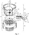
- Fig. 1 schematically illustrates a solid state lighting device 101 comprising a solid state lighting module 102 and a socket 103.
- the solid state lighting module 102 comprises a printed circuit board 107, a plurality of solid state light-sources, in the form of light-emitting diodes (LEDs) 112, a heat-spreader 104, a substantially cylindrical housing 105, a reflector 108, an optically transmissive top cover 106, and fastening means, here in the form of protrusions or lugs 109.
- the LEDs 112 are electrically and thermally connected to the printed circuit board 107, which is in turn thermally connected to the heat spreader 104, in order to dissipate heat generated by the LEDs 112 during operation thereof.
- the cylindrical housing 105 and the top cover 106 are arranged to form a housing enclosing the LEDs 112, and the reflector 108 is arranged inside this housing to collimate the light emitted by the LEDs 112.
- the socket 103 comprises a heat sink 110 and fastening means in the form of recesses 113.
- the solid state lighting module 102 is attached to the socket 103 by axially inserting the lugs 109 of the solid state lighting module 102 in the corresponding recesses 113 of the socket and rotating the solid state lighting module 102 about the axis 111 of rotation as is schematically indicated in fig 1 . Due to the configuration of the lugs 109 and the recesses 113, the solid state lighting device is then locked to the socket in such a way that the heat spreader 104 is pressed against the heat sink 110. At the same time, the LEDs are connected to electrical power via connection means (not shown in fig 1 ) comprised in the socket 103 for electrically connecting the LEDs 112 of the solid state lighting module 102.
- thermal connection between the heat spreader 104 and the heat sink 110 is achieved.
- this thermal connection is improved compared to the prior art by increasing the contact area between the heat spreader 104 and the heat sink 110 through a suitable surface topography of the heat spreader 104 and the heat sink 110.
- the heat spreader 104 has a first surface 114 facing the LEDs 112, and a second surface 115 facing away from the LEDs 112 (and towards the heat sink 110 when the solid state lighting module is attached to the socket 103).
- the second surface 114 has a surface topography with a plurality of peaks 119 and valleys 120 arranged substantially concentrically in respect of the axis of rotation 111. This allows for rotational attachment and an increased thermal contact area when the solid state lighting module 102 is attached to a suitable socket 103.
- Such a socket 103 may have a heat sink that has a surface topography that is substantially the inverse of the surface topography of the heat spreader 104 of the solid state lighting module 102, as is schematically indicated in fig 1 .
- the heat sink 110 of the socket 103 in fig 1 comprises a top surface 116 facing the receiving opening of the socket 103.
- the top surface 116 has a surface topography with a plurality of peaks 117 and valleys 118 that are arranged concentrically in respect of the axis 111 of rotation in an inverse configuration as compared to the peaks 119 and valleys 120 of the heat spreader 104.
- the heat sink 110 may be made of a material that conforms to the surface topography of the heat spreader 104.
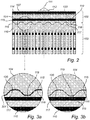
- Fig 2 which is a schematic partial cross-section view of the solid state lighting device 101 in fig. 1 , illustrates the increased thermal contact area that is achieved when the heat spreader 104 of the solid state lighting module 102 is pressed against the heat sink 110 of the socket 103 because of the surface topography with corresponding peaks and valleys of the heat spreader 104.
- the surface topography with corresponding peaks and valleys of the heat spreader 104 and the heat sink 110 schematically illustrated in fig. 1 and fig. 2 increases the thermal contact area as compared to a conventional arrangement with a flat heat spreader pressed against a flat heat sink.
- a further increase in thermal contact area can be achieved by also handling micro-scale surface variations of the heat spreader 104 and/or the heat sink 110 that otherwise may lead to microscopic air pockets between the heat spreader 104 and the heat sink 110.
- a thermal interface material 301 such as so-called thermal grease may be provided between the heat spreader 104 and the heat sink 110. This will further increase the thermal contact area between the heat spreader 104 and the heat sink 110.
- thermal grease may, for example, comprise thermally conductive ceramic fillers dispersed in silicone or hydrocarbon oils.
- the heat spreader 104 may comprise a metal that is sufficiently soft to be plastically deformed on a micro scale by the micro variations on the surface 116 of the (harder) heat sink 110 when the solid state lighting module 102 is attached to the socket 103 through rotation.
- the inventors have found that a metal having a hardness below 60 on the Brinell hardness scale is sufficiently soft to conform to the micro variations of the surface 116 of the heat sink 110 so as to achieve the desired increased thermal contact area.
- the pressure and the friction between the heat spreader 104 and the heat sink 110 resulting from the rotational attachment of the solid state lighting module 102 to the socket 103 forces the metal at the second surface 115 of the heat spreader 104 to conform to the microscopic variations in the surface 116 of the heat sink 110.
- suitable metals having a hardness below 60 on the Brinell scale include, for example, pure aluminum, tin, lead and silver.
- aluminum from the A1 1000 series can be used for the part of the heat spreading member facing the heat sink 110.
- Figs. 4a-b schematically illustrate a third embodiment of the solid state lighting module 102 according to the present invention.
- the heat spreader 104 comprises a thin corrugated metal sheet being spring loaded and biased away from the LEDs 112.
- the heat spreader conforms to micro variations in the heat sink 110, whereby the thermal contact area is increased.
- the heat sink 110 comprised in the socket may comprise a metal having a hardness of below 60 on the Brinell scale, or a spring loaded thin metal sheet as described above in respect of the heat spreader 104 comprised in the solid state lighting module 102.
Landscapes
- Engineering & Computer Science (AREA)
- General Engineering & Computer Science (AREA)
- Physics & Mathematics (AREA)
- Microelectronics & Electronic Packaging (AREA)
- Optics & Photonics (AREA)
- General Physics & Mathematics (AREA)
- Automation & Control Theory (AREA)
- Arrangement Of Elements, Cooling, Sealing, Or The Like Of Lighting Devices (AREA)
- Non-Portable Lighting Devices Or Systems Thereof (AREA)
- Fastening Of Light Sources Or Lamp Holders (AREA)
- Led Device Packages (AREA)
Claims (9)
- Dispositif d'éclairage à semi-conducteur (101) comprenant un module d'éclairage à semi-conducteur (102) et une douille (103) pour recevoir le module d'éclairage à semi-conducteur (102) par l'intermédiaire de rotation autour d'un axe de rotation (111), ledit module d'éclairage à semi-conducteur (102) comprenant :au moins une source de lumière à semi-conducteur (112) ;un organe à étalement de chaleur (104) possédant une première surface (114) et une seconde surface (115) agencées de façon opposée l'une à l'autre et en connexion thermique l'une avec l'autre, ladite première surface (114) étant en connexion thermique avec ladite au moins une source de lumière à semi-conducteur (112) ; etun moyen de fixation (109) agencé pour coopérer avec un moyen de fixation correspondant (113) compris dans ladite douille (103) pour mettre la seconde surface (115) dudit organe à étalement de chaleur (104) en connexion thermique avec un dissipateur de chaleur (110) compris dans ladite douille (103) ;caractérisé en ce que ladite douille (103) comprendun dissipateur de chaleur (110) ; etun moyen de fixation (113) coopérant avec le moyen de fixation correspondant (109) compris dans ledit module d'éclairage à semi-conducteur (102) et fournissant une connexion thermique entre une surface (116) dudit dissipateur de chaleur (110) et la seconde surface (115) de l'organe à étalement de chaleur (104) compris dans ledit module d'éclairage à semi-conducteur (102),dans lequel la seconde surface (115) dudit organe à étalement de chaleur (104) possède une topographie de surface avec une pluralité de crêtes (119) et de creux (120) agencés de façon sensiblement concentrique par rapport audit axe de rotation (111) et dans lequel la topographie de surface de la surface (116) du dissipateur de chaleur (110) est sensiblement un inverse de la topographie de surface de la seconde surface (115) de l'organe à étalement de chaleur (104) et la surface (116) dudit dissipateur de chaleur comprend un matériau déformable.
- Module d'éclairage à semi-conducteur (102) selon la revendication 1, dans lequel une distance dans une direction perpendiculaire audit axe de rotation (111) entre des crêtes (119) et/ou creux (120) voisins est au moins 0,5 mm.
- Module d'éclairage à semi-conducteur (102) selon l'une quelconque des revendications précédentes, dans lequel une amplitude crête-à-crête entre ladite crête (119) et ledit creux (120) est au moins 250 µm.
- Module d'éclairage à semi-conducteur (102) selon l'une quelconque des revendications précédentes, dans lequel chacun de ladite crête (119) et dudit creux (120) est arrondi.
- Module d'éclairage à semi-conducteur (102) selon la revendication 4, dans lequel chacun de ladite crête (119) et dudit creux (120) possède un rayon de courbure d'au moins 0,5 mm.
- Module d'éclairage à semi-conducteur (102) selon l'une quelconque des revendications précédentes, dans lequel une portion de l'organe à étalement de chaleur (104) tournée à l'opposée des sources de lumière à semi-conducteur (112) est faite d'un métal possédant une dureté inférieure à 60 sur l'échelle de dureté de Brinell.
- Module d'éclairage à semi-conducteur (102) selon l'une quelconque des revendications 1 à 5, dans lequel l'organe à étalement de chaleur (104) comprend une feuille métallique agencée sous forme de ressort sollicité pour fléchir dans une direction vers les sources de lumière à semi-conducteur (112) lorsque l'organe à étalement de chaleur (104) est mis en contact avec le dissipateur de chaleur (110) compris dans la douille lors de la fixation du module d'éclairage à semi-conducteur (102) à la douille (103).
- Module d'éclairage à semi-conducteur (102) selon l'une quelconque des revendications précédentes, dans lequel la seconde surface (115) de l'organe à étalement de chaleur (104) est au moins partiellement couverte avec un matériau d'interface thermique (301).
- Module d'éclairage à semi-conducteur (102) selon la revendication 8, comprenant en outre un revêtement sur la seconde surface (115) de l'organe à étalement de chaleur (104) agencé pour couvrir au moins partiellement ledit matériau d'interface thermique (301) pour réduire la friction entre l'organe à étalement de chaleur et le dissipateur de chaleur compris dans la douille durant la fixation dudit module d'éclairage à semi-conducteur (102) à ladite douille (103).
Applications Claiming Priority (2)
| Application Number | Priority Date | Filing Date | Title |
|---|---|---|---|
| US201161560847P | 2011-11-17 | 2011-11-17 | |
| PCT/IB2012/056177 WO2013072805A1 (fr) | 2011-11-17 | 2012-11-06 | Module d'éclairage à semi-conducteurs à dissipateur de chaleur amélioré |
Publications (2)
| Publication Number | Publication Date |
|---|---|
| EP2748529A1 EP2748529A1 (fr) | 2014-07-02 |
| EP2748529B1 true EP2748529B1 (fr) | 2017-01-11 |
Family
ID=47459043
Family Applications (1)
| Application Number | Title | Priority Date | Filing Date |
|---|---|---|---|
| EP12808480.3A Not-in-force EP2748529B1 (fr) | 2011-11-17 | 2012-11-06 | Module d'éclairage à semi-conducteurs à dissipateur de chaleur amélioré |
Country Status (5)
| Country | Link |
|---|---|
| US (1) | US9175843B2 (fr) |
| EP (1) | EP2748529B1 (fr) |
| JP (1) | JP6045597B2 (fr) |
| CN (1) | CN103946631B (fr) |
| WO (1) | WO2013072805A1 (fr) |
Families Citing this family (5)
| Publication number | Priority date | Publication date | Assignee | Title |
|---|---|---|---|---|
| EP2857744A1 (fr) * | 2013-10-07 | 2015-04-08 | Hella KGaA Hueck & Co | Module à LED et système d'éclairage |
| CN105090769B (zh) * | 2014-05-20 | 2018-04-13 | 赛尔富电子有限公司 | 一种具有转动灯头的led灯 |
| JP6628140B2 (ja) * | 2016-03-03 | 2020-01-08 | パナソニックIpマネジメント株式会社 | 照明装置 |
| US10281131B2 (en) | 2017-03-30 | 2019-05-07 | Brandon Cohen | Heat dispersion element |
| US10177515B2 (en) * | 2017-05-17 | 2019-01-08 | Eaton Intelligent Power Limited | Lug assemblies and related electrical apparatus and methods |
Family Cites Families (13)
| Publication number | Priority date | Publication date | Assignee | Title |
|---|---|---|---|---|
| GB2203827A (en) | 1987-04-24 | 1988-10-26 | Northwich Plumbing & Heating S | Central heating radiators |
| US5989070A (en) * | 1998-02-20 | 1999-11-23 | Al-Turki; Ali | Bulb socket adapter |
| NL1028678C2 (nl) * | 2005-04-01 | 2006-10-03 | Lemnis Lighting Ip Gmbh | Koellichaam, lamp en werkwijze voor het vervaardigen van een koellichaam. |
| JP4740682B2 (ja) * | 2005-08-01 | 2011-08-03 | 三菱電機株式会社 | Led照明装置 |
| JP2007088100A (ja) * | 2005-09-20 | 2007-04-05 | Matsushita Electric Works Ltd | 照明器具 |
| US7710045B2 (en) | 2006-03-17 | 2010-05-04 | 3M Innovative Properties Company | Illumination assembly with enhanced thermal conductivity |
| US7694727B2 (en) | 2007-01-23 | 2010-04-13 | Fu Zhun Precision Industry (Shen Zhen) Co., Ltd. | Heat dissipation device with multiple heat pipes |
| CN101711326B (zh) * | 2007-05-08 | 2012-12-05 | 科锐公司 | 照明装置和照明方法 |
| US8220980B2 (en) | 2008-09-23 | 2012-07-17 | Tyco Electronics Corporation | Socket assembly for light-emitting devices |
| TWM398081U (en) * | 2009-03-16 | 2011-02-11 | Molex Inc | Light module and light apparatus |
| EP2284440A1 (fr) * | 2009-08-14 | 2011-02-16 | Koninklijke Philips Electronics N.V. | Connecteur pour la connexion d'un composant à un dissipateur de chaleur |
| WO2010146509A1 (fr) * | 2009-06-17 | 2010-12-23 | Koninklijke Philips Electronics N.V. | Connecteur pour connecter un composant à un puits de chaleur |
| WO2011050256A1 (fr) | 2009-10-22 | 2011-04-28 | Thermal Solution Resources, Llc | Ensemble d'éclairage à led surmoulé et procédé de fabrication |
-
2012
- 2012-11-06 EP EP12808480.3A patent/EP2748529B1/fr not_active Not-in-force
- 2012-11-06 JP JP2014541779A patent/JP6045597B2/ja not_active Expired - Fee Related
- 2012-11-06 CN CN201280056712.4A patent/CN103946631B/zh not_active Expired - Fee Related
- 2012-11-06 WO PCT/IB2012/056177 patent/WO2013072805A1/fr active Application Filing
- 2012-11-06 US US14/358,914 patent/US9175843B2/en not_active Expired - Fee Related
Non-Patent Citations (1)
| Title |
|---|
| None * |
Also Published As
| Publication number | Publication date |
|---|---|
| US20140334153A1 (en) | 2014-11-13 |
| CN103946631B (zh) | 2017-10-24 |
| EP2748529A1 (fr) | 2014-07-02 |
| CN103946631A (zh) | 2014-07-23 |
| WO2013072805A1 (fr) | 2013-05-23 |
| JP2015502637A (ja) | 2015-01-22 |
| US9175843B2 (en) | 2015-11-03 |
| JP6045597B2 (ja) | 2016-12-14 |
Similar Documents
| Publication | Publication Date | Title |
|---|---|---|
| US11402071B2 (en) | Lighting devices that comprise one or more solid state light emitters | |
| JP4917697B2 (ja) | ランプ及び照明装置 | |
| US8403522B2 (en) | LED lamp | |
| US8602579B2 (en) | Lighting devices including thermally conductive housings and related structures | |
| US9464801B2 (en) | Lighting device with one or more removable heat sink elements | |
| US9964257B2 (en) | Illumination device for preventing a removal of a module substrate and suppressing generation of a crack in the module substrate | |
| EP2604091B1 (fr) | Dispositifs d'éclairage doté de composants lumineux de moteur amovibles, éléments et procédé de dispositif d'éclairage | |
| JP5688295B2 (ja) | 照明器具組立体およびled組立体 | |
| EP2748529B1 (fr) | Module d'éclairage à semi-conducteurs à dissipateur de chaleur amélioré | |
| US20090141508A1 (en) | Lamp with heat conducting structure and lamp cover thereof | |
| US8678632B2 (en) | Replaceable light emitting diode module with high optical precision | |
| US10636950B2 (en) | Lighting device and method of making lighting device | |
| TW201207300A (en) | Lighting module | |
| WO2011100224A2 (fr) | Dispositifs d'éclairage comprenant un ou plusieurs émetteurs de lumière à semi-conducteurs | |
| US20150330615A1 (en) | Optical semiconductor illuminating apparatus | |
| US8350450B2 (en) | LED lamp | |
| US20090284933A1 (en) | Combination type heat dissipation module | |
| CN105698041A (zh) | 光学半导体照明设备 | |
| TWM400561U (en) | Light emitting diode illumination apparatus | |
| KR20120095689A (ko) | 조명 장치 |
Legal Events
| Date | Code | Title | Description |
|---|---|---|---|
| PUAI | Public reference made under article 153(3) epc to a published international application that has entered the european phase |
Free format text: ORIGINAL CODE: 0009012 |
|
| 17P | Request for examination filed |
Effective date: 20140324 |
|
| AK | Designated contracting states |
Kind code of ref document: A1 Designated state(s): AL AT BE BG CH CY CZ DE DK EE ES FI FR GB GR HR HU IE IS IT LI LT LU LV MC MK MT NL NO PL PT RO RS SE SI SK SM TR |
|
| DAX | Request for extension of the european patent (deleted) | ||
| GRAP | Despatch of communication of intention to grant a patent |
Free format text: ORIGINAL CODE: EPIDOSNIGR1 |
|
| RIC1 | Information provided on ipc code assigned before grant |
Ipc: F21V 29/70 20150101ALI20160527BHEP Ipc: F21V 29/74 20150101ALI20160527BHEP Ipc: F21Y 105/00 20160101ALI20160527BHEP Ipc: F21V 19/00 20060101ALI20160527BHEP Ipc: F21V 19/04 20060101ALI20160527BHEP Ipc: F21V 29/00 20150101ALI20160527BHEP Ipc: F21V 17/14 20060101AFI20160527BHEP Ipc: F21K 99/00 20160101ALI20160527BHEP Ipc: F21V 29/76 20150101ALI20160527BHEP Ipc: G05D 23/24 20060101ALI20160527BHEP |
|
| RIN1 | Information on inventor provided before grant (corrected) |
Inventor name: CREUSEN, MARTINUS PETRUS Inventor name: TREURNIET, THEODOOR CORNELIS Inventor name: PEETERS,HENRICUS MARIE |
|
| INTG | Intention to grant announced |
Effective date: 20160704 |
|
| RAP1 | Party data changed (applicant data changed or rights of an application transferred) |
Owner name: PHILIPS LIGHTING HOLDING B.V. |
|
| GRAS | Grant fee paid |
Free format text: ORIGINAL CODE: EPIDOSNIGR3 |
|
| GRAA | (expected) grant |
Free format text: ORIGINAL CODE: 0009210 |
|
| AK | Designated contracting states |
Kind code of ref document: B1 Designated state(s): AL AT BE BG CH CY CZ DE DK EE ES FI FR GB GR HR HU IE IS IT LI LT LU LV MC MK MT NL NO PL PT RO RS SE SI SK SM TR |
|
| REG | Reference to a national code |
Ref country code: GB Ref legal event code: FG4D |
|
| REG | Reference to a national code |
Ref country code: CH Ref legal event code: EP |
|
| REG | Reference to a national code |
Ref country code: AT Ref legal event code: REF Ref document number: 861643 Country of ref document: AT Kind code of ref document: T Effective date: 20170115 |
|
| REG | Reference to a national code |
Ref country code: IE Ref legal event code: FG4D |
|
| REG | Reference to a national code |
Ref country code: DE Ref legal event code: R096 Ref document number: 602012027815 Country of ref document: DE |
|
| REG | Reference to a national code |
Ref country code: LT Ref legal event code: MG4D |
|
| REG | Reference to a national code |
Ref country code: NL Ref legal event code: MP Effective date: 20170111 |
|
| REG | Reference to a national code |
Ref country code: AT Ref legal event code: MK05 Ref document number: 861643 Country of ref document: AT Kind code of ref document: T Effective date: 20170111 |
|
| PG25 | Lapsed in a contracting state [announced via postgrant information from national office to epo] |
Ref country code: NL Free format text: LAPSE BECAUSE OF FAILURE TO SUBMIT A TRANSLATION OF THE DESCRIPTION OR TO PAY THE FEE WITHIN THE PRESCRIBED TIME-LIMIT Effective date: 20170111 |
|
| PG25 | Lapsed in a contracting state [announced via postgrant information from national office to epo] |
Ref country code: NO Free format text: LAPSE BECAUSE OF FAILURE TO SUBMIT A TRANSLATION OF THE DESCRIPTION OR TO PAY THE FEE WITHIN THE PRESCRIBED TIME-LIMIT Effective date: 20170411 Ref country code: HR Free format text: LAPSE BECAUSE OF FAILURE TO SUBMIT A TRANSLATION OF THE DESCRIPTION OR TO PAY THE FEE WITHIN THE PRESCRIBED TIME-LIMIT Effective date: 20170111 Ref country code: GR Free format text: LAPSE BECAUSE OF FAILURE TO SUBMIT A TRANSLATION OF THE DESCRIPTION OR TO PAY THE FEE WITHIN THE PRESCRIBED TIME-LIMIT Effective date: 20170412 Ref country code: LT Free format text: LAPSE BECAUSE OF FAILURE TO SUBMIT A TRANSLATION OF THE DESCRIPTION OR TO PAY THE FEE WITHIN THE PRESCRIBED TIME-LIMIT Effective date: 20170111 Ref country code: FI Free format text: LAPSE BECAUSE OF FAILURE TO SUBMIT A TRANSLATION OF THE DESCRIPTION OR TO PAY THE FEE WITHIN THE PRESCRIBED TIME-LIMIT Effective date: 20170111 Ref country code: IS Free format text: LAPSE BECAUSE OF FAILURE TO SUBMIT A TRANSLATION OF THE DESCRIPTION OR TO PAY THE FEE WITHIN THE PRESCRIBED TIME-LIMIT Effective date: 20170511 |
|
| RIN2 | Information on inventor provided after grant (corrected) |
Inventor name: PEETERS,HENRICUS MARIE Inventor name: TREURNIET, THEODOOR CORNELIS Inventor name: CREUSEN, MARTINUS PETRUS |
|
| PG25 | Lapsed in a contracting state [announced via postgrant information from national office to epo] |
Ref country code: BG Free format text: LAPSE BECAUSE OF FAILURE TO SUBMIT A TRANSLATION OF THE DESCRIPTION OR TO PAY THE FEE WITHIN THE PRESCRIBED TIME-LIMIT Effective date: 20170411 Ref country code: LV Free format text: LAPSE BECAUSE OF FAILURE TO SUBMIT A TRANSLATION OF THE DESCRIPTION OR TO PAY THE FEE WITHIN THE PRESCRIBED TIME-LIMIT Effective date: 20170111 Ref country code: PL Free format text: LAPSE BECAUSE OF FAILURE TO SUBMIT A TRANSLATION OF THE DESCRIPTION OR TO PAY THE FEE WITHIN THE PRESCRIBED TIME-LIMIT Effective date: 20170111 Ref country code: ES Free format text: LAPSE BECAUSE OF FAILURE TO SUBMIT A TRANSLATION OF THE DESCRIPTION OR TO PAY THE FEE WITHIN THE PRESCRIBED TIME-LIMIT Effective date: 20170111 Ref country code: RS Free format text: LAPSE BECAUSE OF FAILURE TO SUBMIT A TRANSLATION OF THE DESCRIPTION OR TO PAY THE FEE WITHIN THE PRESCRIBED TIME-LIMIT Effective date: 20170111 Ref country code: AT Free format text: LAPSE BECAUSE OF FAILURE TO SUBMIT A TRANSLATION OF THE DESCRIPTION OR TO PAY THE FEE WITHIN THE PRESCRIBED TIME-LIMIT Effective date: 20170111 Ref country code: SE Free format text: LAPSE BECAUSE OF FAILURE TO SUBMIT A TRANSLATION OF THE DESCRIPTION OR TO PAY THE FEE WITHIN THE PRESCRIBED TIME-LIMIT Effective date: 20170111 Ref country code: PT Free format text: LAPSE BECAUSE OF FAILURE TO SUBMIT A TRANSLATION OF THE DESCRIPTION OR TO PAY THE FEE WITHIN THE PRESCRIBED TIME-LIMIT Effective date: 20170511 |
|
| REG | Reference to a national code |
Ref country code: DE Ref legal event code: R097 Ref document number: 602012027815 Country of ref document: DE |
|
| PG25 | Lapsed in a contracting state [announced via postgrant information from national office to epo] |
Ref country code: RO Free format text: LAPSE BECAUSE OF FAILURE TO SUBMIT A TRANSLATION OF THE DESCRIPTION OR TO PAY THE FEE WITHIN THE PRESCRIBED TIME-LIMIT Effective date: 20170111 Ref country code: EE Free format text: LAPSE BECAUSE OF FAILURE TO SUBMIT A TRANSLATION OF THE DESCRIPTION OR TO PAY THE FEE WITHIN THE PRESCRIBED TIME-LIMIT Effective date: 20170111 Ref country code: SK Free format text: LAPSE BECAUSE OF FAILURE TO SUBMIT A TRANSLATION OF THE DESCRIPTION OR TO PAY THE FEE WITHIN THE PRESCRIBED TIME-LIMIT Effective date: 20170111 Ref country code: CZ Free format text: LAPSE BECAUSE OF FAILURE TO SUBMIT A TRANSLATION OF THE DESCRIPTION OR TO PAY THE FEE WITHIN THE PRESCRIBED TIME-LIMIT Effective date: 20170111 Ref country code: IT Free format text: LAPSE BECAUSE OF FAILURE TO SUBMIT A TRANSLATION OF THE DESCRIPTION OR TO PAY THE FEE WITHIN THE PRESCRIBED TIME-LIMIT Effective date: 20170111 |
|
| PLBE | No opposition filed within time limit |
Free format text: ORIGINAL CODE: 0009261 |
|
| STAA | Information on the status of an ep patent application or granted ep patent |
Free format text: STATUS: NO OPPOSITION FILED WITHIN TIME LIMIT |
|
| REG | Reference to a national code |
Ref country code: FR Ref legal event code: PLFP Year of fee payment: 6 |
|
| PG25 | Lapsed in a contracting state [announced via postgrant information from national office to epo] |
Ref country code: SM Free format text: LAPSE BECAUSE OF FAILURE TO SUBMIT A TRANSLATION OF THE DESCRIPTION OR TO PAY THE FEE WITHIN THE PRESCRIBED TIME-LIMIT Effective date: 20170111 Ref country code: DK Free format text: LAPSE BECAUSE OF FAILURE TO SUBMIT A TRANSLATION OF THE DESCRIPTION OR TO PAY THE FEE WITHIN THE PRESCRIBED TIME-LIMIT Effective date: 20170111 |
|
| 26N | No opposition filed |
Effective date: 20171012 |
|
| PG25 | Lapsed in a contracting state [announced via postgrant information from national office to epo] |
Ref country code: SI Free format text: LAPSE BECAUSE OF FAILURE TO SUBMIT A TRANSLATION OF THE DESCRIPTION OR TO PAY THE FEE WITHIN THE PRESCRIBED TIME-LIMIT Effective date: 20170111 |
|
| PG25 | Lapsed in a contracting state [announced via postgrant information from national office to epo] |
Ref country code: MC Free format text: LAPSE BECAUSE OF FAILURE TO SUBMIT A TRANSLATION OF THE DESCRIPTION OR TO PAY THE FEE WITHIN THE PRESCRIBED TIME-LIMIT Effective date: 20170111 |
|
| PG25 | Lapsed in a contracting state [announced via postgrant information from national office to epo] |
Ref country code: LI Free format text: LAPSE BECAUSE OF NON-PAYMENT OF DUE FEES Effective date: 20171130 Ref country code: CH Free format text: LAPSE BECAUSE OF NON-PAYMENT OF DUE FEES Effective date: 20171130 |
|
| PG25 | Lapsed in a contracting state [announced via postgrant information from national office to epo] |
Ref country code: LU Free format text: LAPSE BECAUSE OF NON-PAYMENT OF DUE FEES Effective date: 20171106 |
|
| REG | Reference to a national code |
Ref country code: BE Ref legal event code: MM Effective date: 20171130 |
|
| REG | Reference to a national code |
Ref country code: IE Ref legal event code: MM4A |
|
| PG25 | Lapsed in a contracting state [announced via postgrant information from national office to epo] |
Ref country code: MT Free format text: LAPSE BECAUSE OF NON-PAYMENT OF DUE FEES Effective date: 20171106 |
|
| PG25 | Lapsed in a contracting state [announced via postgrant information from national office to epo] |
Ref country code: IE Free format text: LAPSE BECAUSE OF NON-PAYMENT OF DUE FEES Effective date: 20171106 |
|
| PG25 | Lapsed in a contracting state [announced via postgrant information from national office to epo] |
Ref country code: BE Free format text: LAPSE BECAUSE OF NON-PAYMENT OF DUE FEES Effective date: 20171130 |
|
| PG25 | Lapsed in a contracting state [announced via postgrant information from national office to epo] |
Ref country code: HU Free format text: LAPSE BECAUSE OF FAILURE TO SUBMIT A TRANSLATION OF THE DESCRIPTION OR TO PAY THE FEE WITHIN THE PRESCRIBED TIME-LIMIT; INVALID AB INITIO Effective date: 20121106 |
|
| PG25 | Lapsed in a contracting state [announced via postgrant information from national office to epo] |
Ref country code: CY Free format text: LAPSE BECAUSE OF NON-PAYMENT OF DUE FEES Effective date: 20170111 |
|
| PG25 | Lapsed in a contracting state [announced via postgrant information from national office to epo] |
Ref country code: MK Free format text: LAPSE BECAUSE OF FAILURE TO SUBMIT A TRANSLATION OF THE DESCRIPTION OR TO PAY THE FEE WITHIN THE PRESCRIBED TIME-LIMIT Effective date: 20170111 |
|
| PGFP | Annual fee paid to national office [announced via postgrant information from national office to epo] |
Ref country code: FR Payment date: 20191126 Year of fee payment: 8 |
|
| PG25 | Lapsed in a contracting state [announced via postgrant information from national office to epo] |
Ref country code: TR Free format text: LAPSE BECAUSE OF FAILURE TO SUBMIT A TRANSLATION OF THE DESCRIPTION OR TO PAY THE FEE WITHIN THE PRESCRIBED TIME-LIMIT Effective date: 20170111 |
|
| PGFP | Annual fee paid to national office [announced via postgrant information from national office to epo] |
Ref country code: DE Payment date: 20191230 Year of fee payment: 8 Ref country code: GB Payment date: 20191128 Year of fee payment: 8 |
|
| PG25 | Lapsed in a contracting state [announced via postgrant information from national office to epo] |
Ref country code: AL Free format text: LAPSE BECAUSE OF FAILURE TO SUBMIT A TRANSLATION OF THE DESCRIPTION OR TO PAY THE FEE WITHIN THE PRESCRIBED TIME-LIMIT Effective date: 20170111 |
|
| REG | Reference to a national code |
Ref country code: DE Ref legal event code: R119 Ref document number: 602012027815 Country of ref document: DE |
|
| GBPC | Gb: european patent ceased through non-payment of renewal fee |
Effective date: 20201106 |
|
| PG25 | Lapsed in a contracting state [announced via postgrant information from national office to epo] |
Ref country code: FR Free format text: LAPSE BECAUSE OF NON-PAYMENT OF DUE FEES Effective date: 20201130 |
|
| PG25 | Lapsed in a contracting state [announced via postgrant information from national office to epo] |
Ref country code: GB Free format text: LAPSE BECAUSE OF NON-PAYMENT OF DUE FEES Effective date: 20201106 Ref country code: DE Free format text: LAPSE BECAUSE OF NON-PAYMENT OF DUE FEES Effective date: 20210601 |