EP2746881B1 - Machine control system employing lathe tool and cutter - Google Patents
Machine control system employing lathe tool and cutter Download PDFInfo
- Publication number
- EP2746881B1 EP2746881B1 EP13197298.6A EP13197298A EP2746881B1 EP 2746881 B1 EP2746881 B1 EP 2746881B1 EP 13197298 A EP13197298 A EP 13197298A EP 2746881 B1 EP2746881 B1 EP 2746881B1
- Authority
- EP
- European Patent Office
- Prior art keywords
- module
- feeding module
- cutter
- lathe
- along
- Prior art date
- Legal status (The legal status is an assumption and is not a legal conclusion. Google has not performed a legal analysis and makes no representation as to the accuracy of the status listed.)
- Active
Links
- 238000005520 cutting process Methods 0.000 claims description 70
- 238000003754 machining Methods 0.000 claims description 22
- 230000002093 peripheral effect Effects 0.000 description 36
- 238000003801 milling Methods 0.000 description 18
- 238000007790 scraping Methods 0.000 description 17
- 238000000034 method Methods 0.000 description 15
- 238000004519 manufacturing process Methods 0.000 description 2
- 230000003247 decreasing effect Effects 0.000 description 1
- 239000002184 metal Substances 0.000 description 1
- 238000012986 modification Methods 0.000 description 1
- 230000004048 modification Effects 0.000 description 1
Images


Classifications
-
- B—PERFORMING OPERATIONS; TRANSPORTING
- B23—MACHINE TOOLS; METAL-WORKING NOT OTHERWISE PROVIDED FOR
- B23B—TURNING; BORING
- B23B3/00—General-purpose turning-machines or devices, e.g. centre lathes with feed rod and lead screw; Sets of turning-machines
- B23B3/06—Turning-machines or devices characterised only by the special arrangement of constructional units
- B23B3/065—Arrangements for performing other machining operations, e.g. milling, drilling
-
- B—PERFORMING OPERATIONS; TRANSPORTING
- B23—MACHINE TOOLS; METAL-WORKING NOT OTHERWISE PROVIDED FOR
- B23Q—DETAILS, COMPONENTS, OR ACCESSORIES FOR MACHINE TOOLS, e.g. ARRANGEMENTS FOR COPYING OR CONTROLLING; MACHINE TOOLS IN GENERAL CHARACTERISED BY THE CONSTRUCTION OF PARTICULAR DETAILS OR COMPONENTS; COMBINATIONS OR ASSOCIATIONS OF METAL-WORKING MACHINES, NOT DIRECTED TO A PARTICULAR RESULT
- B23Q39/00—Metal-working machines incorporating a plurality of sub-assemblies, each capable of performing a metal-working operation
- B23Q39/02—Metal-working machines incorporating a plurality of sub-assemblies, each capable of performing a metal-working operation the sub-assemblies being capable of being brought to act at a single operating station
- B23Q39/021—Metal-working machines incorporating a plurality of sub-assemblies, each capable of performing a metal-working operation the sub-assemblies being capable of being brought to act at a single operating station with a plurality of toolheads per workholder, whereby the toolhead is a main spindle, a multispindle, a revolver or the like
- B23Q39/022—Metal-working machines incorporating a plurality of sub-assemblies, each capable of performing a metal-working operation the sub-assemblies being capable of being brought to act at a single operating station with a plurality of toolheads per workholder, whereby the toolhead is a main spindle, a multispindle, a revolver or the like with same working direction of toolheads on same workholder
- B23Q39/024—Metal-working machines incorporating a plurality of sub-assemblies, each capable of performing a metal-working operation the sub-assemblies being capable of being brought to act at a single operating station with a plurality of toolheads per workholder, whereby the toolhead is a main spindle, a multispindle, a revolver or the like with same working direction of toolheads on same workholder consecutive working of toolheads
-
- B—PERFORMING OPERATIONS; TRANSPORTING
- B23—MACHINE TOOLS; METAL-WORKING NOT OTHERWISE PROVIDED FOR
- B23P—METAL-WORKING NOT OTHERWISE PROVIDED FOR; COMBINED OPERATIONS; UNIVERSAL MACHINE TOOLS
- B23P23/00—Machines or arrangements of machines for performing specified combinations of different metal-working operations not covered by a single other subclass
- B23P23/02—Machine tools for performing different machining operations
-
- B—PERFORMING OPERATIONS; TRANSPORTING
- B23—MACHINE TOOLS; METAL-WORKING NOT OTHERWISE PROVIDED FOR
- B23Q—DETAILS, COMPONENTS, OR ACCESSORIES FOR MACHINE TOOLS, e.g. ARRANGEMENTS FOR COPYING OR CONTROLLING; MACHINE TOOLS IN GENERAL CHARACTERISED BY THE CONSTRUCTION OF PARTICULAR DETAILS OR COMPONENTS; COMBINATIONS OR ASSOCIATIONS OF METAL-WORKING MACHINES, NOT DIRECTED TO A PARTICULAR RESULT
- B23Q39/00—Metal-working machines incorporating a plurality of sub-assemblies, each capable of performing a metal-working operation
- B23Q2039/008—Machines of the lathe type
Definitions
- the present disclosure generally relates to cutting machine control system, and particularly, to a machine control system employing lathe tool and cutter.
- Such machine control system is known from EP1952937 A1 and CN201524905U .
- CNC computer numerical control
- the CNC machine may be adapted for one machine method to machine a workpiece.
- the workpiece may undergo a number of machine methods to obtain a surface finish as required.
- an electronic device such as a desktop computer or a mobile phone may have a machined housing made of metal.
- the metallic housing includes a top portion and a peripheral sidewall extending from a peripheral edge of the top portion.
- the top portion has a greater surface area than that of the peripheral sidewall and has a non-circular flat surface or non-circular curved surface.
- the peripheral sidewall has four side surfaces arranged in order and adjacent two side surfaces are connected by corners.
- a machine control system employing a lathe tool and a cutter includes an input module, a worktable, a first sliding module, a second sliding module, a lathe feeding module, a lathe tool connected to the lathe feeding module, a cutting feeding module, a cutter connected to the cutting feeding module, and a control module.
- the control module is electrically connected to the input module, the worktable, the first sliding module, the second sliding module, the lathe feeding module, and the cutting feeding module.
- the first sliding module is controlled by the input module inputting control parameters.
- the first sliding module drives the second sliding module to slide along a first direction, the control module controls the second sliding module.
- the second sliding module drives the lathe feeding module and the cutting feeding module to slide along a second direction perpendicular to the first direction.
- the lathe feeding module controls the lathe tool to slide along a third direction perpendicular to the first direction and the second direction reciprocally
- the cutting feeding module controls the cutter to slide along the third direction and rotate along a first axis parallel to the third direction
- the cutting feeding module is a milling or a scraping feeding module.
- the cutter is a milling cutter corresponding to the milling feeding module when the cutting feeding module is the milling feeding module, or the cutter is a scraping cutter corresponding to the scraping feeding module when the cutting feeding module is the scraping feeding module.
- a machine control system employing lathe tool and cutter includes an input module, a worktable, a first sliding module, a second sliding module, a lathe feeding module, a lathe tool assembled to the lathe feeding module, a cutting feeding module, a cutter assembled to the cutting feeding module, and a control module electrically connected to the input module, the worktable, the first sliding module, the second sliding module, the lathe feeding module, and the cutting feeding module.
- control module controls the first sliding module
- the first sliding module drives the second sliding module to slide along a first direction
- the first sliding module controls the second sliding module to drive the lathe feeding module and the cutting feeding module to slide along a second direction perpendicular to the first direction
- the lathe feeding module controls the lathe tool to slide along a third direction perpendicular to the first direction and the second direction reciprocally
- the cutting feeding module controls the cutter to slide along the third direction and rotate along a first axis parallel to the third direction
- the control module controls the worktable to rotate along a second axis parallel to the third direction
- the cutting feeding module is a milling feeding module or a scraping feeding module
- the cutter is a milling cutter corresponding to the milling feeding module when the cutting feeding module is the milling feeding module
- the cutter is a scraping cutter corresponding to the scraping feeding module when the cutting feeding module is the scraping feeding module.
- FIG. 1 shows an embodiment of a machine 200 for machining a metallic member 300 (see FIG. 3 ).
- the machine 200 includes an input module 10, a machine support 11, a worktable 12, a first sliding module 13, a second sliding module 14, a lathe feeding module 15, a cutting feeding module 17, and a control module 20 electrically connected to the input module 10.
- the input module 10 is mounted on a side of the machine support 11.
- the control module 20 is mounted on a side of the input module 10 and is electrically connected to the input module 10.
- the worktable 12 is rotatably mounted on the machine support 11.
- the first sliding module 13 is slidably mounted on the machine support 11 and is positioned above the worktable 12.
- the second sliding module 14 is sidably mounted on the first sliding module 13.
- the lathe feeding module 15 and the cutting feeding module 17 are arranged side by side and slidably mounted on the second sliding module 14.
- the metallic member 300 is held on the worktable 12.
- a lathe tool 151 is assembled to the lathe feeding module 15, a cutter 171 is assembled to the cutting feeding module 17.
- the first sliding module 13, the second sliding module 14, the lathe feeding module 15, and the cutting feeding module 17 are electrically connected to the control module 20. Under the control of the control module 20, the first sliding module 13 drives the second sliding module 14 to move along the X axis (a first direction).
- the second sliding module 14 moves the lathe feeding module 15 and the cutting feeding module 17 along the Y axis (a second direction).
- the lathe feeding module 15 drives the lathe tool 151 to slide along the Z axis (a third direction) reciprocating at a high speed.
- the cutting feeding module 17 drives the cutter 171 to slide along the Z axis and rotates the cutter 171 along ayaxis (parallel to the third direction).
- the worktable 12 rotates the metallic member 300 along aaaxis (parallel to the second direction) and a ⁇ axis (parallel to the third direction).
- the cutting feeding module 17 is a milling feeding module
- the cutter 171 is a milling cutter.
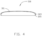
- FIGS. 3 and 4 shows that the metallic member 300 to be machined is a housing of a mobile phone.
- the metallic member 300 is substantially rectangular and hollow, and includes a top portion 301 and a peripheral sidewall 303 extending from a peripheral edge of the top portion 301.
- the top portion 301 has a curved surface with a relatively greater surface area than that of the peripheral sidewall 303, the curved surface is a non-rotatable three-dimensional curved surface.
- the peripheral sidewall 303 has four side surfaces 3031 arranged in order and every two of the adjacent side surfaces 3031 are connected by a corner 3033.
- the four side surfaces 3031 are substantially flat surfaces, each corner 3033 interconnects two adjacent side surfaces 3031.
- the peripheral sidewall 303 further includes an end edge 305 away from the top portion 301.
- the top portion 301, the peripheral sidewall 303 and the end edge 305 of the metallic member 300 are to be machined by the machine 200 in that order.
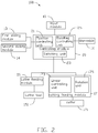
- FIG. 2 shows a machine control system 100 adapted by the machine 200 for machining the metallic member 300.
- the machine control system 100 is a modularization of the machine 200, and includes the input module 10, the control module 20, the worktable 12, the first sliding module 13, the second sliding module 14, the lathe feeding module 15, and the cutting feeding module 17.
- the input module 10 is electrically connected to the control module 20 for entering a number of control parameters and transferring the control parameters to the control module 20.
- the control parameters include moving range, moving speed of the lathe feeding module 15 and the cutting feeding module 17 along the X axis and the Y axis, frequency and moving range of the lathe tool 151 along the Z axis, as well as the rotating speed of the cutter 171 along the ⁇ axis, and the rotating speed of the worktable 12.
- the control module 20 is assembled to the input module 10 and electrically connected to the input module 10.
- the control module 20 is further electrically connected to the worktable 12, the first sliding module 13, the second sliding module 14, the lathe feeding module 15, the lathe tool 151, the cutting feeding module 17, and the cutter 171 for controlling the machine 200.
- the control module 20 includes a position control unit 21, a switching unit 23, and a rotation control unit 25.
- the position control unit 21 is electrically connected to the first sliding module 13 and the second sliding module 40, to control the first sliding module 13 and the second sliding module 40 to move the lathe feeding module 15, and the cutting feeding module 17 along the X/Y axis.
- the switching unit 23 is electrically connected to the lathe feeding module 15 and the cutting feeding module 17, for switching executing between the lathe feeding module 15 and the cutting feeding module 17.
- the rotation control unit 25 is electrically connected to the worktable 12 to control the rotation of the worktable 12. In the embodiment, the rotation speed of the worktable 12 along the ⁇ axis is 100-900 round/minute.
- the lathe tool 151 is assembled to a tool holder (not labeled) of the lathe feeding module 15, the cutter 171 is rotatably assembled to the cutting feeding module 17.
- the lathe feeding module 15 drives the lathe tool 151 to move along the Z axis reciprocally at a high frequency about 500-3200 Hz.
- the cutting feeding module 17 further includes a linear control unit 173 and a rotation unit 175.
- the linear control unit 173 drives the cutter 171 to move along the Z axis.
- the rotation unit 175 rotates the cutter 171 along the ⁇ axis.
- the machine movement of the machine 200 is simulated to machine the top portion 301, the peripheral sidewall 203, and the end edge 305, thereby obtaining a number of control parameters.
- the control parameters of machining the top portion 301, the peripheral sidewall 203, and the end edge 30 are typed into the input module 10, that is, typing the control parameters of different machine process, such as moving ranges, moving speeds of the lathe feeding module 15 and the cutting feeding module 17 along the X axis and the Y axis, frequency and moving range of the lathe tool 151 along the Z axis, rotating speed of the cutter 171 along the ⁇ axis, and the rotating speed of the worktable 12.
- the surface finish of the top portion 301 is 0.2-1 micrometer.
- the peripheral sidewall 303, and the end edge 305 can illustrate the control procedure of the machine control system 100.
- control parameters are input into the input module 10 to control the machine process for machining the top portion 301 of the metallic member 300.
- the original machine point of the metallic member 300 is located at a middle of an edge of the metallic member 300 which is arranged parallel to the X axis.
- the terminal machine point of the metallic member 300 is located at a center of the metallic member 300, such that, when starting machining, the lathe tool 151 just moves along the Y axis toward the center of the metallic member 300.
- the moving range H of the lathe tool 151 along the Z axis is decreased along the Y axis toward the center of the metallic member 300 automatically, according to a preset mode.
- the rotating speed r1 of the worktable 12 along the ⁇ axis is up to 600 round/minute.
- the frequency f of lathe tool 151 along the Z axis is 2500 Hz.
- Input control parameters into the input module 10 to control the machine process for machining the end edge 305 of the metallic member 300 In detail, typing the rotating angles of the worktable 12 along the ⁇ and ⁇ axis, the moving ranges of the cutting feeding module 17 along the X axis and the Y axis, the moving speeds V3 of the cutter 171 along the X axis and the Y axis, the machining time t3 of the cutter 171 machining the peripheral sidewall 303, the rotating speed r3 of the cutter 171 into the input module 10, and selecting the predetermined machining path of the cutter 171 in the input module 10. Then, the cutter 171 machines the end edge 305 along a periphery of the metallic member 300.
- the switching unit 23 transmits control signals to the position control unit 21 and the lathe feeding module 15.
- the position control unit 21 controls the first sliding module 13 to drive the lathe feeding module 15 along the Y axis.
- the position control unit 21 controls the second sliding module 14 to drive the lathe feeding module 15 to move along the Y axis at a moving speed v1 automatically.
- the rotating control unit 25 controls the worktable 12 to rotate the metallic member 300 along theaaxis at a rotation speed r1 round/minute, and the control module 20 controls the lathe feeding module 15 to drive the lathe tool 151 to move along the Z axis reciprocally at a frequency f and a moving range H.
- the moving range H is changed due to the Y position of the lathe tool 151 automatically.
- the movement track 400 of the lathe tool 151 projected on the top portion 301 is spiral.
- the lathe tool 151 is moved from a point A on the edge of the top portion 301 toward the central point O of the top portion 301 along the spiral movement track 400, thereby finishing the machining of the top portion 301.
- the surface finish of the top portion 301 is about 0.25-0.3 micrometer.
- the switching unit 23 transfers signal to the position control unit 21 and the cutting feeding module 17.
- the position control unit 21 controls the lathe feeding module 15 to move away from the metallic member 300, and controls the first sliding module 13 and the second sliding module 14 to drive the cutting feeding module 17 toward the metallic member 300 along the X axis and the Y axis, till the cutting feeding module 17 arrives at the peripheral sidewall 303 of the metallic member 300.
- the cutting feeding module 17 drives the cutter 171 to mill the peripheral sidewall 303.
- the cutter 171 mills the peripheral sidewall 303.
- the linear control unit 173 controls the cutter 171 to move along the Z axis till the cutter 171 arrives at a predetermined position of the peripheral sidewall 303.
- the rotation unit 175 rotates the cutter 171 along the ⁇ axis at a rotation speed r2 to mill the peripheral sidewall 303
- the first sliding module 13 and the second sliding module 14 drives the cutter 171 to move relative to the metallic member 300 along the X axis and the Y axis at a speed v2 according a predetermined path
- the cutting feeding module 17 controls a feed of the cutter 171 relative to the metallic member 300, thereby finishing the milling of the peripheral sidewall 303.
- the worktable 90 remains still.
- the rotating control unit 25 may transmit signal the worktable 12 to rotate along the ⁇ axis to match the cutter 171 milling the peripheral sidewall 303.
- the surface finish of the peripheral sidewall 303 may be any suitable for the worktable 171 and the peripheral sidewall
- the position control unit 21 transmits a signal to the first sliding module 13 and the second sliding module 14. So, the first sliding module 13 and the second sliding module 14 drive the cutting feeding module 17 away from the metallic member 300. In addition, the cutting feeding module 17 holds to stop rotating and milling.
- the rotating control unit 25 controls the worktable 12 to rotate along the ⁇ axis to turn the end edge 305 toward the cutter 171. Then, the first sliding module 13 and the second sliding module 14 drive the cutting feeding module 17 toward the end edge 305 till the cutter 171 resists a preset portion on the end edge 305.
- the first sliding module 13 and the second sliding module 14 drive the cutter 171 to move along a predetermined path at speed V3, simultaneously, the rotation unit 175 rotates the cutter 171 at a rotation speed r3 round/minute and the cutting feeding module 17 controls a chamfering feed of the cutter 171 relative to the metallic member 300.
- the rotation control unit 25 transmits a control signal to the worktable 12 and rotates the worktable 12 along the ⁇ axis and the ⁇ axis to adjust a position of the metallic member 300, thereby enabling a side of the end edge 305 to be moved to face the cutter 171.
- the first sliding module 13 and the second sliding module 14 drive the cutter 171 to move to chamfer the end edge 305 in similar procedure, until the chamfering of the end edge 305 of the metallic member 300 is finished.
- the machine control system 100 may first mill the peripheral sidewall 303 and the end edge 305, then the top portion 301 is machined by the lathe tool 151.
- the worktable 12 has multi-axis rotation under the control of the rotating control unit 25.
- the cutting feeding module 14 moves along a determined path to match the multi-axis rotation of the worktable 12 to mill the metallic member 300.
- the machine control system 100 machines the top portion 301 into different shapes with the lathe tool 151.
- the original machine point of the metallic member 300 When machining the top portion 301, the original machine point of the metallic member 300 may be located at a middle of an edge of the top position 301 parallel to the Y axis.
- the terminal machine point of the metallic member 300 is located at a central of the top portion 301 of the metallic member 300, such that the lathe tool 151 moves along the X axis toward the central of the top portion 301.
- the original machine point may be located at the central of the top portion 301, and the terminal machine point may be located at the edge of the top portion 301.
- the machine control system 100 machines the top portion 301, the peripheral sidewall 303, and the end edge 305 at the same time and obtains a high surface finish.
- the lathe feeding module 15 drives the lathe tool 151 to move along the Z axis reciprocally at a high speed, thus the lathe tool 171 machine the top portion 301 continuously in a spiral track, thereby obtaining a high surface finish on the top portion 301.
- the cutting feeding module 17 drives the cutter 171 along the predetermined path to mill the peripheral sidewall 303 of the metallic member 300.
- the rotation control unit 25 controls the worktable 12 to rotate, thereby matching the cutting feeding module 17 to chamfer the end edge 305.
- the cutting feeding mechanism 17 can be a scraping feeding module, and the cutter 171 can be a scraping cutter corresponding the scraping feeding module. Parameters of scraping are input into the input module 10. Process of the cutting feeding mechanism 17 and the cutter 171 scraping the workpiece 300 is described in detail. In the scraping process, the cutter 171 scrapes the peripheral sidewall 303. First, the linear control unit 173 controls the cutter 171 to move along the Z axis until the cutter 171 arrives at a predetermined position of the peripheral sidewall 303.
- the first sliding module 13 and the second sliding module 14 drives the cutter 171 to scrap the metallic member 300 along the X axis and the Y axis at a speed v2, according a predetermined path, the cutting feeding module 17 simultaneously controls a feed of the cutter 171 relative to the metallic member 300.
- the position control unit 21 controls the first sliding module 13 and the second sliding module 14 to adjust a forward direction of the cutting feeding module 17, and the rotation unit 175 simultaneously controls the cutting feeding module 17 to drive the cutter 171 to rotate along the ⁇ axis at a rotation speed r2, thereby enabling the cutter 171 to scrap the corner 3033 along a tangent direction of the corner 3033.
- the rotation unit 175 controls the cutting feeding module 17 to stop rotating, and scrap the next side surface 3031 linearly at a moving speed V2.
- the cutter 171 scrapes the four side surface 3031 one by one, thereby accomplishing the scraping of the peripheral sidewall 303.
- the worktable 90 remains still.
- the rotation control unit 25 may transmit signal the worktable 12 to rotate along the ⁇ axis to match the cutter 171 scraping the peripheral sidewall 303.
- the position control unit 21 transmits a signal to the first sliding module 13 and the second sliding module 14. So, the first sliding module 13 and the second sliding module 14 drive the cutting feeding module 17 away from the metallic member 300. In addition, the cutting feeding module 17 holds to stop rotating and scraping.
- the rotation control unit 25 controls the worktable 12 to rotate along the ⁇ axis to turn the end edge 305 toward the cutter 171. Then, the first sliding module 13 and the second sliding module 14 drive the cutting feeding module 17 toward the end edge 305 till the cutter 171 resists a preset portion on the end edge 305.
- the first sliding module 13 and the second sliding module 14 drive the cutter 171 to move along a predetermined path at speed V3, s the cutting feeding module 17 simultaneously controls a chamfering feed of the cutter 171 relative to the metallic member 300.
- the position control unit 21 controls the first sliding module 13 and the second sliding module 14 to adjust a forward direction of the cutting feeding module 17, and simultaneously the rotation unit 175 controls the cutting feeding module 17 to drive the cutter 171 to rotate along the ⁇ axis at a rotation speed r2, thereby enabling the cutter 171 to scrap the end edge 305 on the corner 3033 along a tangent direction.
- the rotation unit 175 stops the cutting feeding module 17 from rotating.
- the rotation control unit 25 transmits controlling signal to the worktable 12 and rotates the worktable 12 along the ⁇ axis and the ⁇ axis to adjust a position of the metallic member 300, thereby enabling a side of the end edge 305 next to the side had been scraped to face the cutter 171.
- the first sliding module 13 and the second sliding module 14 drive the cutter 171 to move to chamfer the end edge 305 in similar procedure, until finishing chamfering the end edge 305 of the metallic member 300.
Landscapes
- Engineering & Computer Science (AREA)
- Mechanical Engineering (AREA)
- Milling Processes (AREA)
- Turning (AREA)
Description
- The present disclosure generally relates to cutting machine control system, and particularly, to a machine control system employing lathe tool and cutter. Such machine control system is known from
EP1952937 A1 andCN201524905U . - CNC (computer numerical control) machine is an important device in manufacturing fields and usually is employed to machine workpiece. The CNC machine may be adapted for one machine method to machine a workpiece. However, due to the limitation of the machine method and the surface finish requirement of the workpiece, it may be difficult to satisfy all the machine requirement of the workpiece using only one machine method. The workpiece may undergo a number of machine methods to obtain a surface finish as required.
- For example, an electronic device such as a desktop computer or a mobile phone may have a machined housing made of metal. The metallic housing includes a top portion and a peripheral sidewall extending from a peripheral edge of the top portion. The top portion has a greater surface area than that of the peripheral sidewall and has a non-circular flat surface or non-circular curved surface. The peripheral sidewall has four side surfaces arranged in order and adjacent two side surfaces are connected by corners. In related manufacturing fields, if a milling machine is employed to machine the metallic housing, some tracks remain on the top portion that has been milled because of intermittent contact and interrupted milling by the cutter. Then a milling process needs to be applied for a better appearance. Therefore, using the milling process may not be efficient. If a lathe machine is employed to machine the metallic member, it is difficult to machine a surface which is not circular. The lathe is not suitable to machine the peripheral sidewalls because of the four corners of the peripheral sidewall. Thus a number of additional machining processes must be added to machine the metallic housing. Machining the electronic devices using a lathe is time-consuming.
- Therefore, there is room for improvement within the art.
- According to one aspect of the disclosure, a machine control system employing a lathe tool and a cutter includes an input module, a worktable, a first sliding module, a second sliding module, a lathe feeding module, a lathe tool connected to the lathe feeding module, a cutting feeding module, a cutter connected to the cutting feeding module, and a control module. The control module is electrically connected to the input module, the worktable, the first sliding module, the second sliding module, the lathe feeding module, and the cutting feeding module. The first sliding module is controlled by the input module inputting control parameters. The first sliding module drives the second sliding module to slide along a first direction, the control module controls the second sliding module. The second sliding module drives the lathe feeding module and the cutting feeding module to slide along a second direction perpendicular to the first direction. The lathe feeding module controls the lathe tool to slide along a third direction perpendicular to the first direction and the second direction reciprocally, and the cutting feeding module controls the cutter to slide along the third direction and rotate along a first axis parallel to the third direction, and the cutting feeding module is a milling or a scraping feeding module. The cutter is a milling cutter corresponding to the milling feeding module when the cutting feeding module is the milling feeding module, or the cutter is a scraping cutter corresponding to the scraping feeding module when the cutting feeding module is the scraping feeding module.
- A machine control system employing lathe tool and cutter, includes an input module, a worktable, a first sliding module, a second sliding module, a lathe feeding module, a lathe tool assembled to the lathe feeding module, a cutting feeding module, a cutter assembled to the cutting feeding module, and a control module electrically connected to the input module, the worktable, the first sliding module, the second sliding module, the lathe feeding module, and the cutting feeding module. Wherein the control module controls the first sliding module, the first sliding module drives the second sliding module to slide along a first direction, the first sliding module controls the second sliding module to drive the lathe feeding module and the cutting feeding module to slide along a second direction perpendicular to the first direction, the lathe feeding module controls the lathe tool to slide along a third direction perpendicular to the first direction and the second direction reciprocally, and the cutting feeding module controls the cutter to slide along the third direction and rotate along a first axis parallel to the third direction, the control module controls the worktable to rotate along a second axis parallel to the third direction, the cutting feeding module is a milling feeding module or a scraping feeding module, the cutter is a milling cutter corresponding to the milling feeding module when the cutting feeding module is the milling feeding module, or the cutter is a scraping cutter corresponding to the scraping feeding module when the cutting feeding module is the scraping feeding module.
- The components in the drawings are not necessarily drawn to scale, the emphasis instead placed upon clearly illustrating the principles of the present disclosure. Moreover, in the drawings, like reference numerals designate corresponding parts throughout the several views.
-
FIG. 1 is an isometric view of an embodiment of a machine. -
FIG. 2 is a machine control system adapted by the machine ofFIG. 1 . -
FIG. 3 is an isometric view of a metallic member to be machined. -
FIG. 4 is a sectional view of the metallic member ofFIG. 3 , taken along line IV-IV ofFIG. 3 . -
FIG. 5 is a movement track of a lathe tool employed by the machine control system. -
FIG. 1 shows an embodiment of amachine 200 for machining a metallic member 300 (seeFIG. 3 ). Themachine 200 includes aninput module 10, amachine support 11, aworktable 12, afirst sliding module 13, asecond sliding module 14, alathe feeding module 15, acutting feeding module 17, and acontrol module 20 electrically connected to theinput module 10. Theinput module 10 is mounted on a side of themachine support 11. Thecontrol module 20 is mounted on a side of theinput module 10 and is electrically connected to theinput module 10. Theworktable 12 is rotatably mounted on themachine support 11. The first slidingmodule 13 is slidably mounted on themachine support 11 and is positioned above theworktable 12. The second slidingmodule 14 is sidably mounted on the first slidingmodule 13. Thelathe feeding module 15 and thecutting feeding module 17 are arranged side by side and slidably mounted on the second slidingmodule 14. Themetallic member 300 is held on theworktable 12. Alathe tool 151 is assembled to thelathe feeding module 15, acutter 171 is assembled to thecutting feeding module 17. Thefirst sliding module 13, thesecond sliding module 14, thelathe feeding module 15, and thecutting feeding module 17 are electrically connected to thecontrol module 20. Under the control of thecontrol module 20, the first slidingmodule 13 drives the second slidingmodule 14 to move along the X axis (a first direction). The second slidingmodule 14 moves thelathe feeding module 15 and thecutting feeding module 17 along the Y axis (a second direction). Thelathe feeding module 15 drives thelathe tool 151 to slide along the Z axis (a third direction) reciprocating at a high speed. Thecutting feeding module 17 drives thecutter 171 to slide along the Z axis and rotates thecutter 171 along ayaxis (parallel to the third direction). Theworktable 12 rotates themetallic member 300 along aaaxis (parallel to the second direction) and aβaxis (parallel to the third direction). In the illustrated embodiment, thecutting feeding module 17 is a milling feeding module, and thecutter 171 is a milling cutter. -
FIGS. 3 and4 shows that themetallic member 300 to be machined is a housing of a mobile phone. Themetallic member 300 is substantially rectangular and hollow, and includes atop portion 301 and aperipheral sidewall 303 extending from a peripheral edge of thetop portion 301. Thetop portion 301 has a curved surface with a relatively greater surface area than that of theperipheral sidewall 303, the curved surface is a non-rotatable three-dimensional curved surface. Theperipheral sidewall 303 has fourside surfaces 3031 arranged in order and every two of theadjacent side surfaces 3031 are connected by acorner 3033. The fourside surfaces 3031 are substantially flat surfaces, eachcorner 3033 interconnects twoadjacent side surfaces 3031. Theperipheral sidewall 303 further includes anend edge 305 away from thetop portion 301. Thetop portion 301, theperipheral sidewall 303 and theend edge 305 of themetallic member 300 are to be machined by themachine 200 in that order. -
FIG. 2 shows amachine control system 100 adapted by themachine 200 for machining themetallic member 300. Themachine control system 100 is a modularization of themachine 200, and includes theinput module 10, thecontrol module 20, theworktable 12, thefirst sliding module 13, thesecond sliding module 14, thelathe feeding module 15, and thecutting feeding module 17. - The
input module 10 is electrically connected to thecontrol module 20 for entering a number of control parameters and transferring the control parameters to thecontrol module 20. The control parameters include moving range, moving speed of thelathe feeding module 15 and thecutting feeding module 17 along the X axis and the Y axis, frequency and moving range of thelathe tool 151 along the Z axis, as well as the rotating speed of thecutter 171 along the γ axis, and the rotating speed of theworktable 12. - The
control module 20 is assembled to theinput module 10 and electrically connected to theinput module 10. Thecontrol module 20 is further electrically connected to theworktable 12, the first slidingmodule 13, the second slidingmodule 14, thelathe feeding module 15, thelathe tool 151, thecutting feeding module 17, and thecutter 171 for controlling themachine 200. Thecontrol module 20 includes aposition control unit 21, a switchingunit 23, and arotation control unit 25. Theposition control unit 21 is electrically connected to the first slidingmodule 13 and the second sliding module 40, to control the first slidingmodule 13 and the second sliding module 40 to move thelathe feeding module 15, and thecutting feeding module 17 along the X/Y axis. The switchingunit 23 is electrically connected to thelathe feeding module 15 and thecutting feeding module 17, for switching executing between thelathe feeding module 15 and thecutting feeding module 17. Therotation control unit 25 is electrically connected to theworktable 12 to control the rotation of theworktable 12. In the embodiment, the rotation speed of theworktable 12 along the β axis is 100-900 round/minute. Thelathe tool 151 is assembled to a tool holder (not labeled) of thelathe feeding module 15, thecutter 171 is rotatably assembled to thecutting feeding module 17. - The
lathe feeding module 15 drives thelathe tool 151 to move along the Z axis reciprocally at a high frequency about 500-3200 Hz. Thecutting feeding module 17 further includes a linear control unit 173 and arotation unit 175. The linear control unit 173 drives thecutter 171 to move along the Z axis. Therotation unit 175 rotates thecutter 171 along the γ axis. - In the embodiment, when manually inputting control parameters into the
input module 10. First, the machine movement of themachine 200 is simulated to machine thetop portion 301, the peripheral sidewall 203, and theend edge 305, thereby obtaining a number of control parameters. Then, the control parameters of machining thetop portion 301, the peripheral sidewall 203, and the end edge 30 are typed into theinput module 10, that is, typing the control parameters of different machine process, such as moving ranges, moving speeds of thelathe feeding module 15 and thecutting feeding module 17 along the X axis and the Y axis, frequency and moving range of thelathe tool 151 along the Z axis, rotating speed of thecutter 171 along the γ axis, and the rotating speed of theworktable 12. The surface finish of thetop portion 301 is 0.2-1 micrometer. - During the process of machining the
top portion 301 using themachine 200, theperipheral sidewall 303, and theend edge 305 can illustrate the control procedure of themachine control system 100. - First, the control parameters are input into the
input module 10 to control the machine process for machining thetop portion 301 of themetallic member 300. In detail, typing the moving ranges of thelathe feeding module 15 along the X axis and the Y axis, the moving speed V1, the machining time t1 of thelathe tool 151 into theinput module 10. The original machine point of themetallic member 300 is located at a middle of an edge of themetallic member 300 which is arranged parallel to the X axis. The terminal machine point of themetallic member 300 is located at a center of themetallic member 300, such that, when starting machining, thelathe tool 151 just moves along the Y axis toward the center of themetallic member 300. Typing the frequency f, the moving range H of thelathe tool 151 along the Z axis, and the rotating speed of theworktable 12 r1 into theinput module 10. The moving range H of thelathe tool 151 along the Z axis is decreased along the Y axis toward the center of themetallic member 300 automatically, according to a preset mode. In the embodiment, the rotating speed r1 of theworktable 12 along the α axis is up to 600 round/minute. The frequency f oflathe tool 151 along the Z axis is 2500 Hz. - Input control parameters into the
input module 10 to control the machine process for machining theperipheral sidewall 303 of themetallic member 300. In detail, typing the moving ranges of thecutting feeding module 17 along the X axis and the Y axis, the moving speed V2, the machining time t2 of thecutter 171 machining theperipheral sidewall 303, the rotating speed r2 of thecutter 171 into theinput module 10, and selecting the predetermined machining path of thecutter 171 in theinput module 10. Then, thecutter 171 machines theperipheral sidewall 303 one by one automatically. - Input control parameters into the
input module 10 to control the machine process for machining theend edge 305 of themetallic member 300. In detail, typing the rotating angles of theworktable 12 along the α and β axis, the moving ranges of thecutting feeding module 17 along the X axis and the Y axis, the moving speeds V3 of thecutter 171 along the X axis and the Y axis, the machining time t3 of thecutter 171 machining theperipheral sidewall 303, the rotating speed r3 of thecutter 171 into theinput module 10, and selecting the predetermined machining path of thecutter 171 in theinput module 10. Then, thecutter 171 machines theend edge 305 along a periphery of themetallic member 300. - The switching
unit 23 transmits control signals to theposition control unit 21 and thelathe feeding module 15. Theposition control unit 21 controls the first slidingmodule 13 to drive thelathe feeding module 15 along the Y axis. In addition, controls the second slidingmodule 14 to drive thelathe feeding module 15 to move along the X axis, thereby positioning thelathe tool 151 above a middle of an edge of thetop portion 301 parallel to the X axis. Then, theposition control unit 21 controls the second slidingmodule 14 to drive thelathe feeding module 15 to move along the Y axis at a moving speed v1 automatically. Simultaneously, therotating control unit 25 controls theworktable 12 to rotate themetallic member 300 along theaaxis at a rotation speed r1 round/minute, and thecontrol module 20 controls thelathe feeding module 15 to drive thelathe tool 151 to move along the Z axis reciprocally at a frequency f and a moving range H. The moving range H is changed due to the Y position of thelathe tool 151 automatically. - Also referring to
FIG. 5 , in the machining procedure of thelathe tool 151 machining thetop portion 301, themovement track 400 of thelathe tool 151 projected on thetop portion 301 is spiral. Thelathe tool 151 is moved from a point A on the edge of thetop portion 301 toward the central point O of thetop portion 301 along thespiral movement track 400, thereby finishing the machining of thetop portion 301. In the embodiment, the surface finish of thetop portion 301 is about 0.25-0.3 micrometer. - When the
lathe tool 151 machines thetop portion 301 for tl minutes, the switchingunit 23 transfers signal to theposition control unit 21 and thecutting feeding module 17. Theposition control unit 21 controls thelathe feeding module 15 to move away from themetallic member 300, and controls the first slidingmodule 13 and the second slidingmodule 14 to drive the cuttingfeeding module 17 toward themetallic member 300 along the X axis and the Y axis, till thecutting feeding module 17 arrives at theperipheral sidewall 303 of themetallic member 300. Thecutting feeding module 17 drives thecutter 171 to mill theperipheral sidewall 303. - In the milling process, the
cutter 171 mills theperipheral sidewall 303. First, the linear control unit 173 controls thecutter 171 to move along the Z axis till thecutter 171 arrives at a predetermined position of theperipheral sidewall 303. Then, therotation unit 175 rotates thecutter 171 along the γ axis at a rotation speed r2 to mill theperipheral sidewall 303, simultaneously, the first slidingmodule 13 and the second slidingmodule 14 drives thecutter 171 to move relative to themetallic member 300 along the X axis and the Y axis at a speed v2 according a predetermined path, and thecutting feeding module 17 controls a feed of thecutter 171 relative to themetallic member 300, thereby finishing the milling of theperipheral sidewall 303. In the embodiment, the worktable 90 remains still. Therotating control unit 25 may transmit signal theworktable 12 to rotate along the α axis to match thecutter 171 milling theperipheral sidewall 303. In the embodiment, the surface finish of theperipheral sidewall 303. - When the
cutter 171 mills theperipheral sidewall 303 for t2 minutes, theposition control unit 21 transmits a signal to the first slidingmodule 13 and the second slidingmodule 14. So, the first slidingmodule 13 and the second slidingmodule 14 drive the cuttingfeeding module 17 away from themetallic member 300. In addition, thecutting feeding module 17 holds to stop rotating and milling. Therotating control unit 25 controls theworktable 12 to rotate along the α axis to turn theend edge 305 toward thecutter 171. Then, the first slidingmodule 13 and the second slidingmodule 14 drive the cuttingfeeding module 17 toward theend edge 305 till thecutter 171 resists a preset portion on theend edge 305. The first slidingmodule 13 and the second slidingmodule 14 drive thecutter 171 to move along a predetermined path at speed V3, simultaneously, therotation unit 175 rotates thecutter 171 at a rotation speed r3 round/minute and thecutting feeding module 17 controls a chamfering feed of thecutter 171 relative to themetallic member 300. When the chamfering of a side of theend edge 305 is finished, therotation control unit 25 transmits a control signal to theworktable 12 and rotates theworktable 12 along the α axis and the β axis to adjust a position of themetallic member 300, thereby enabling a side of theend edge 305 to be moved to face thecutter 171. The first slidingmodule 13 and the second slidingmodule 14 drive thecutter 171 to move to chamfer theend edge 305 in similar procedure, until the chamfering of theend edge 305 of themetallic member 300 is finished. - The
machine control system 100 may first mill theperipheral sidewall 303 and theend edge 305, then thetop portion 301 is machined by thelathe tool 151. Theworktable 12 has multi-axis rotation under the control of therotating control unit 25. Thecutting feeding module 14 moves along a determined path to match the multi-axis rotation of theworktable 12 to mill themetallic member 300. - Changing a relation between the frequency f and the moving range H, the
machine control system 100 machines thetop portion 301 into different shapes with thelathe tool 151. - When machining the
top portion 301, the original machine point of themetallic member 300 may be located at a middle of an edge of thetop position 301 parallel to the Y axis. The terminal machine point of themetallic member 300 is located at a central of thetop portion 301 of themetallic member 300, such that thelathe tool 151 moves along the X axis toward the central of thetop portion 301. In other embodiment, the original machine point may be located at the central of thetop portion 301, and the terminal machine point may be located at the edge of thetop portion 301. - The
machine control system 100 machines thetop portion 301, theperipheral sidewall 303, and theend edge 305 at the same time and obtains a high surface finish. When the first slidingmodule 13 moves thelathe feeding module 15 along the X axis or the second slidingmodule 14 moves thelathe feeding module 15 along the Y axis, simultaneously, thelathe feeding module 15 drives thelathe tool 151 to move along the Z axis reciprocally at a high speed, thus thelathe tool 171 machine thetop portion 301 continuously in a spiral track, thereby obtaining a high surface finish on thetop portion 301. Thecutting feeding module 17 drives thecutter 171 along the predetermined path to mill theperipheral sidewall 303 of themetallic member 300. Then therotation control unit 25 controls theworktable 12 to rotate, thereby matching thecutting feeding module 17 to chamfer theend edge 305. - In another embodiment, the
cutting feeding mechanism 17 can be a scraping feeding module, and thecutter 171 can be a scraping cutter corresponding the scraping feeding module. Parameters of scraping are input into theinput module 10. Process of thecutting feeding mechanism 17 and thecutter 171 scraping theworkpiece 300 is described in detail. In the scraping process, thecutter 171 scrapes theperipheral sidewall 303. First, the linear control unit 173 controls thecutter 171 to move along the Z axis until thecutter 171 arrives at a predetermined position of theperipheral sidewall 303. Then, the first slidingmodule 13 and the second slidingmodule 14 drives thecutter 171 to scrap themetallic member 300 along the X axis and the Y axis at a speed v2, according a predetermined path, thecutting feeding module 17 simultaneously controls a feed of thecutter 171 relative to themetallic member 300. When thecutter 171 arrives at thecorner 3033, theposition control unit 21 controls the first slidingmodule 13 and the second slidingmodule 14 to adjust a forward direction of thecutting feeding module 17, and therotation unit 175 simultaneously controls thecutting feeding module 17 to drive thecutter 171 to rotate along the γ axis at a rotation speed r2, thereby enabling thecutter 171 to scrap thecorner 3033 along a tangent direction of thecorner 3033. When thecutter 171 arrives atside surface 3031 next to the scrappedside surface 3031, therotation unit 175 controls thecutting feeding module 17 to stop rotating, and scrap thenext side surface 3031 linearly at a moving speed V2. Thecutter 171 scrapes the fourside surface 3031 one by one, thereby accomplishing the scraping of theperipheral sidewall 303. In the embodiment, the worktable 90 remains still. Therotation control unit 25 may transmit signal theworktable 12 to rotate along the α axis to match thecutter 171 scraping theperipheral sidewall 303. - When the
cutter 171 scrapes theperipheral sidewall 303 for t2 minutes, theposition control unit 21 transmits a signal to the first slidingmodule 13 and the second slidingmodule 14. So, the first slidingmodule 13 and the second slidingmodule 14 drive the cuttingfeeding module 17 away from themetallic member 300. In addition, thecutting feeding module 17 holds to stop rotating and scraping. Therotation control unit 25 controls theworktable 12 to rotate along the α axis to turn theend edge 305 toward thecutter 171. Then, the first slidingmodule 13 and the second slidingmodule 14 drive the cuttingfeeding module 17 toward theend edge 305 till thecutter 171 resists a preset portion on theend edge 305. The first slidingmodule 13 and the second slidingmodule 14 drive thecutter 171 to move along a predetermined path at speed V3, s the cuttingfeeding module 17 simultaneously controls a chamfering feed of thecutter 171 relative to themetallic member 300. When thecutter 171 arrives at thecorner 3031, theposition control unit 21 controls the first slidingmodule 13 and the second slidingmodule 14 to adjust a forward direction of thecutting feeding module 17, and simultaneously therotation unit 175 controls thecutting feeding module 17 to drive thecutter 171 to rotate along the γ axis at a rotation speed r2, thereby enabling thecutter 171 to scrap theend edge 305 on thecorner 3033 along a tangent direction. When thecutter 171 arrives at theend edge 305 on aside surface 3031 next to the scrappedend edge 305, therotation unit 175 stops thecutting feeding module 17 from rotating. Therotation control unit 25 transmits controlling signal to theworktable 12 and rotates theworktable 12 along the α axis and the β axis to adjust a position of themetallic member 300, thereby enabling a side of theend edge 305 next to the side had been scraped to face thecutter 171. The first slidingmodule 13 and the second slidingmodule 14 drive thecutter 171 to move to chamfer theend edge 305 in similar procedure, until finishing chamfering theend edge 305 of themetallic member 300. - While the present disclosure has been described with reference to particular embodiments, the description is illustrative of the disclosure and is not to be construed as limiting the disclosure. Therefore, various modifications can be made to the embodiments by those of ordinary skill in the art without departing from the scope of the disclosure, as defined by the appended claims.
Claims (4)
- A machine control system employing a lathe tool and a cutter, comprising:an input module (10);a worktable (12);a first sliding module (13);a second sliding module (14);a lathe feeding module (15);a lathe tool (151) connected to the lathe feeding module (15);a cutting feeding module (17);a cutter (171) connected to the cutting feeding module (17), anda control module (20) electrically connected to the input module (10), the worktable (12), the first sliding module (13), the second sliding module (14), the lathe feeding module (15), and the cutting feeding module (17), wherein the first sliding module (13) is controlled by the input module (10) inputting control parameters, the first sliding module (13) drives the second sliding module (14) to slide along a first direction, the control module (20) controls the second sliding module (14), the second sliding module (14) drives the lathe feeding module (15) and the cutting feeding module (17) to slide along a second direction perpendicular to the first direction, the lathe feeding module (15) controls the lathe tool (151) to slide along a third direction perpendicular to the first direction and the second direction reciprocally at a high speed, and the worktable (12) drives a metallic member (300) to rotate, a distance of a reciprocating movement of the lathe tool (151) in the third direction varies with a movement of the lathe tool (151) in the first direction, thereby machining a top portion (301) with a three dimensional curved surface of the metallic member (300), the cutting feeding module (17) controls the cutter (171) to slide along the third direction and rotate along a first axis parallel to the third direction, and the worktable (12) is configured to rotate around a second axis parallel to the third direction; andwherein the control module (20) further comprises a rotating controlling unit (25) electrically connected to the worktable to control the worktable to rotate.
- The machine control system of claim 1, wherein the cutting feeding module (17) comprises a linear control unit (173) and a rotation unit (175), the linear control unit (173) controls the cutter (171) to move along the third direction, and the rotation unit (175) controls the cutter (171) to rotate along the first axis.
- The machine control system of claim 1 or 2, wherein the control module (20) comprises a position control unit (21) and a switching unit (23), the position control unit is electrically connected to the first sliding module (13) and the second sliding module (14), the position control unit controls the first sliding module and the second sliding module to move the lathe feeding module, and the cutting feeding module along the first direction and the second direction, the switching unit is electrically connected to the lathe feeding module and the cutting feeding module, and the switching unit switches executions between the lathe feeding module and the cutting feeding module.
- The machine control system of any of claims 1 to 3 , wherein the control parameters comprises moving ranges, moving speeds of the lathe feeding module and the cutting feeding module along the first direction and the second direction, frequency and moving ranges of the lathe tool along the third direction, rotating speed of the cutter along the first axis, and a rotating speed of the worktable.
Applications Claiming Priority (2)
| Application Number | Priority Date | Filing Date | Title |
|---|---|---|---|
| CN201210554041.6A CN103878636B (en) | 2012-12-19 | 2012-12-19 | Machine tool control system |
| CN201210554031.2A CN103878635B (en) | 2012-12-19 | 2012-12-19 | Machine tool control system |
Publications (3)
| Publication Number | Publication Date |
|---|---|
| EP2746881A2 EP2746881A2 (en) | 2014-06-25 |
| EP2746881A3 EP2746881A3 (en) | 2015-07-01 |
| EP2746881B1 true EP2746881B1 (en) | 2021-10-27 |
Family
ID=49766975
Family Applications (1)
| Application Number | Title | Priority Date | Filing Date |
|---|---|---|---|
| EP13197298.6A Active EP2746881B1 (en) | 2012-12-19 | 2013-12-13 | Machine control system employing lathe tool and cutter |
Country Status (1)
| Country | Link |
|---|---|
| EP (1) | EP2746881B1 (en) |
Families Citing this family (1)
| Publication number | Priority date | Publication date | Assignee | Title |
|---|---|---|---|---|
| CN112743240B (en) * | 2020-12-29 | 2023-06-02 | 深圳精科视觉科技有限公司 | Laser cutting device for mechanical parts |
Citations (2)
| Publication number | Priority date | Publication date | Assignee | Title |
|---|---|---|---|---|
| EP1925397A1 (en) * | 2006-11-24 | 2008-05-28 | Towa Corporation | Method of and apparatus for working structure |
| EP1952937A1 (en) * | 2007-01-30 | 2008-08-06 | Yamazaki Mazak Corporation | Machining center with two main spindle units |
Family Cites Families (2)
| Publication number | Priority date | Publication date | Assignee | Title |
|---|---|---|---|---|
| DE102009058649A1 (en) * | 2009-12-16 | 2011-06-22 | Adams, Heinz, 66740 | Drilling-milling machine has additional rotary tool-carriage that is horizontally arranged on milling carriage in movable manner, where rotary tool holders are arranged with rotary tools before milling head |
| DE102011105402A1 (en) * | 2011-06-20 | 2012-12-20 | Heinz Adams | Milling, turning, grinding machine for workpiece, has vertically movable vertical milling-turning slide and vertically movable vertical grinding rotary plunger movably vertically installed adjacent to each other on Y-bar slide |
-
2013
- 2013-12-13 EP EP13197298.6A patent/EP2746881B1/en active Active
Patent Citations (2)
| Publication number | Priority date | Publication date | Assignee | Title |
|---|---|---|---|---|
| EP1925397A1 (en) * | 2006-11-24 | 2008-05-28 | Towa Corporation | Method of and apparatus for working structure |
| EP1952937A1 (en) * | 2007-01-30 | 2008-08-06 | Yamazaki Mazak Corporation | Machining center with two main spindle units |
Also Published As
| Publication number | Publication date |
|---|---|
| EP2746881A2 (en) | 2014-06-25 |
| EP2746881A3 (en) | 2015-07-01 |
Similar Documents
| Publication | Publication Date | Title |
|---|---|---|
| US10220481B2 (en) | Machine control system employing lathe tool and milling cutter | |
| EP2745959B1 (en) | Machine tool with lathe tool and scraping cutter | |
| US20140172146A1 (en) | Machine control system employing lathe tool and scraping cutter | |
| US9381580B2 (en) | Milling method for machining metallic member | |
| CN103192265B (en) | Numerical control drilling and tapping all-in-one machine and control method thereof | |
| US20140165348A1 (en) | Machine tool with lathe tool and milling cutter | |
| US9550257B2 (en) | Method for machining metallic member using lathing and milling | |
| CN107214521B (en) | Turning and milling combined drilling and tapping center | |
| US20140165371A1 (en) | Method for machining metallic member using lathing and milling | |
| US9566648B2 (en) | Lathe control system | |
| EP2687309A2 (en) | Workpiece having non-rotary curved surface machined by lathe | |
| CN103204626A (en) | Punching and cutting device for touch screen glass and processing method | |
| US9718153B2 (en) | Method for machining metallic member using lathing and scraping | |
| EP2746881B1 (en) | Machine control system employing lathe tool and cutter | |
| CN104801988B (en) | Numerical control machine tool with multi-axial machining function | |
| EP2745960B1 (en) | Method for machining metallic member using lathing and milling | |
| US9757824B2 (en) | Method for machining metallic member using lathing and scraping | |
| CN104801989B (en) | A kind of numerically-controlled machine tool with Multi-axis Machining function | |
| CN104827353A (en) | Numerical control machining center with multi-axis and multi-surface machining function | |
| CN203212457U (en) | Touch screen glass punching and cutting device | |
| CN105690215A (en) | Numerical-control grinding machine for machining hard alloy milling blade | |
| EP2745962A2 (en) | Method for machining metallic member using lathing and scraping | |
| CN104801990A (en) | Numerical control machine tool with multi-axis machining function |
Legal Events
| Date | Code | Title | Description |
|---|---|---|---|
| 17P | Request for examination filed |
Effective date: 20131213 |
|
| AK | Designated contracting states |
Kind code of ref document: A2 Designated state(s): AL AT BE BG CH CY CZ DE DK EE ES FI FR GB GR HR HU IE IS IT LI LT LU LV MC MK MT NL NO PL PT RO RS SE SI SK SM TR |
|
| AX | Request for extension of the european patent |
Extension state: BA ME |
|
| PUAI | Public reference made under article 153(3) epc to a published international application that has entered the european phase |
Free format text: ORIGINAL CODE: 0009012 |
|
| PUAL | Search report despatched |
Free format text: ORIGINAL CODE: 0009013 |
|
| AK | Designated contracting states |
Kind code of ref document: A3 Designated state(s): AL AT BE BG CH CY CZ DE DK EE ES FI FR GB GR HR HU IE IS IT LI LT LU LV MC MK MT NL NO PL PT RO RS SE SI SK SM TR |
|
| AX | Request for extension of the european patent |
Extension state: BA ME |
|
| RIC1 | Information provided on ipc code assigned before grant |
Ipc: B23Q 39/02 20060101ALI20150522BHEP Ipc: B23B 3/06 20060101ALI20150522BHEP Ipc: B23P 23/02 20060101ALI20150522BHEP Ipc: G05B 19/18 20060101AFI20150522BHEP |
|
| R17P | Request for examination filed (corrected) |
Effective date: 20151103 |
|
| RBV | Designated contracting states (corrected) |
Designated state(s): AL AT BE BG CH CY CZ DE DK EE ES FI FR GB GR HR HU IE IS IT LI LT LU LV MC MK MT NL NO PL PT RO RS SE SI SK SM TR |
|
| STAA | Information on the status of an ep patent application or granted ep patent |
Free format text: STATUS: EXAMINATION IS IN PROGRESS |
|
| 17Q | First examination report despatched |
Effective date: 20190408 |
|
| STAA | Information on the status of an ep patent application or granted ep patent |
Free format text: STATUS: EXAMINATION IS IN PROGRESS |
|
| GRAP | Despatch of communication of intention to grant a patent |
Free format text: ORIGINAL CODE: EPIDOSNIGR1 |
|
| STAA | Information on the status of an ep patent application or granted ep patent |
Free format text: STATUS: GRANT OF PATENT IS INTENDED |
|
| INTG | Intention to grant announced |
Effective date: 20210615 |
|
| RAP1 | Party data changed (applicant data changed or rights of an application transferred) |
Owner name: FUXIANG PRECISION INDUSTRIAL (KUNSHAN) CO., LTD. |
|
| GRAS | Grant fee paid |
Free format text: ORIGINAL CODE: EPIDOSNIGR3 |
|
| GRAA | (expected) grant |
Free format text: ORIGINAL CODE: 0009210 |
|
| STAA | Information on the status of an ep patent application or granted ep patent |
Free format text: STATUS: THE PATENT HAS BEEN GRANTED |
|
| AK | Designated contracting states |
Kind code of ref document: B1 Designated state(s): AL AT BE BG CH CY CZ DE DK EE ES FI FR GB GR HR HU IE IS IT LI LT LU LV MC MK MT NL NO PL PT RO RS SE SI SK SM TR |
|
| REG | Reference to a national code |
Ref country code: GB Ref legal event code: FG4D |
|
| REG | Reference to a national code |
Ref country code: CH Ref legal event code: EP |
|
| REG | Reference to a national code |
Ref country code: AT Ref legal event code: REF Ref document number: 1442333 Country of ref document: AT Kind code of ref document: T Effective date: 20211115 |
|
| REG | Reference to a national code |
Ref country code: DE Ref legal event code: R096 Ref document number: 602013079785 Country of ref document: DE |
|
| REG | Reference to a national code |
Ref country code: IE Ref legal event code: FG4D |
|
| REG | Reference to a national code |
Ref country code: LT Ref legal event code: MG9D |
|
| REG | Reference to a national code |
Ref country code: NL Ref legal event code: MP Effective date: 20211027 |
|
| REG | Reference to a national code |
Ref country code: AT Ref legal event code: MK05 Ref document number: 1442333 Country of ref document: AT Kind code of ref document: T Effective date: 20211027 |
|
| PG25 | Lapsed in a contracting state [announced via postgrant information from national office to epo] |
Ref country code: RS Free format text: LAPSE BECAUSE OF FAILURE TO SUBMIT A TRANSLATION OF THE DESCRIPTION OR TO PAY THE FEE WITHIN THE PRESCRIBED TIME-LIMIT Effective date: 20211027 Ref country code: LT Free format text: LAPSE BECAUSE OF FAILURE TO SUBMIT A TRANSLATION OF THE DESCRIPTION OR TO PAY THE FEE WITHIN THE PRESCRIBED TIME-LIMIT Effective date: 20211027 Ref country code: FI Free format text: LAPSE BECAUSE OF FAILURE TO SUBMIT A TRANSLATION OF THE DESCRIPTION OR TO PAY THE FEE WITHIN THE PRESCRIBED TIME-LIMIT Effective date: 20211027 Ref country code: BG Free format text: LAPSE BECAUSE OF FAILURE TO SUBMIT A TRANSLATION OF THE DESCRIPTION OR TO PAY THE FEE WITHIN THE PRESCRIBED TIME-LIMIT Effective date: 20220127 Ref country code: AT Free format text: LAPSE BECAUSE OF FAILURE TO SUBMIT A TRANSLATION OF THE DESCRIPTION OR TO PAY THE FEE WITHIN THE PRESCRIBED TIME-LIMIT Effective date: 20211027 |
|
| PG25 | Lapsed in a contracting state [announced via postgrant information from national office to epo] |
Ref country code: IS Free format text: LAPSE BECAUSE OF FAILURE TO SUBMIT A TRANSLATION OF THE DESCRIPTION OR TO PAY THE FEE WITHIN THE PRESCRIBED TIME-LIMIT Effective date: 20220227 Ref country code: SE Free format text: LAPSE BECAUSE OF FAILURE TO SUBMIT A TRANSLATION OF THE DESCRIPTION OR TO PAY THE FEE WITHIN THE PRESCRIBED TIME-LIMIT Effective date: 20211027 Ref country code: PT Free format text: LAPSE BECAUSE OF FAILURE TO SUBMIT A TRANSLATION OF THE DESCRIPTION OR TO PAY THE FEE WITHIN THE PRESCRIBED TIME-LIMIT Effective date: 20220228 Ref country code: PL Free format text: LAPSE BECAUSE OF FAILURE TO SUBMIT A TRANSLATION OF THE DESCRIPTION OR TO PAY THE FEE WITHIN THE PRESCRIBED TIME-LIMIT Effective date: 20211027 Ref country code: NO Free format text: LAPSE BECAUSE OF FAILURE TO SUBMIT A TRANSLATION OF THE DESCRIPTION OR TO PAY THE FEE WITHIN THE PRESCRIBED TIME-LIMIT Effective date: 20220127 Ref country code: NL Free format text: LAPSE BECAUSE OF FAILURE TO SUBMIT A TRANSLATION OF THE DESCRIPTION OR TO PAY THE FEE WITHIN THE PRESCRIBED TIME-LIMIT Effective date: 20211027 Ref country code: LV Free format text: LAPSE BECAUSE OF FAILURE TO SUBMIT A TRANSLATION OF THE DESCRIPTION OR TO PAY THE FEE WITHIN THE PRESCRIBED TIME-LIMIT Effective date: 20211027 Ref country code: HR Free format text: LAPSE BECAUSE OF FAILURE TO SUBMIT A TRANSLATION OF THE DESCRIPTION OR TO PAY THE FEE WITHIN THE PRESCRIBED TIME-LIMIT Effective date: 20211027 Ref country code: GR Free format text: LAPSE BECAUSE OF FAILURE TO SUBMIT A TRANSLATION OF THE DESCRIPTION OR TO PAY THE FEE WITHIN THE PRESCRIBED TIME-LIMIT Effective date: 20220128 Ref country code: ES Free format text: LAPSE BECAUSE OF FAILURE TO SUBMIT A TRANSLATION OF THE DESCRIPTION OR TO PAY THE FEE WITHIN THE PRESCRIBED TIME-LIMIT Effective date: 20211027 |
|
| REG | Reference to a national code |
Ref country code: DE Ref legal event code: R097 Ref document number: 602013079785 Country of ref document: DE |
|
| PG25 | Lapsed in a contracting state [announced via postgrant information from national office to epo] |
Ref country code: SM Free format text: LAPSE BECAUSE OF FAILURE TO SUBMIT A TRANSLATION OF THE DESCRIPTION OR TO PAY THE FEE WITHIN THE PRESCRIBED TIME-LIMIT Effective date: 20211027 Ref country code: SK Free format text: LAPSE BECAUSE OF FAILURE TO SUBMIT A TRANSLATION OF THE DESCRIPTION OR TO PAY THE FEE WITHIN THE PRESCRIBED TIME-LIMIT Effective date: 20211027 Ref country code: RO Free format text: LAPSE BECAUSE OF FAILURE TO SUBMIT A TRANSLATION OF THE DESCRIPTION OR TO PAY THE FEE WITHIN THE PRESCRIBED TIME-LIMIT Effective date: 20211027 Ref country code: MC Free format text: LAPSE BECAUSE OF FAILURE TO SUBMIT A TRANSLATION OF THE DESCRIPTION OR TO PAY THE FEE WITHIN THE PRESCRIBED TIME-LIMIT Effective date: 20211027 Ref country code: EE Free format text: LAPSE BECAUSE OF FAILURE TO SUBMIT A TRANSLATION OF THE DESCRIPTION OR TO PAY THE FEE WITHIN THE PRESCRIBED TIME-LIMIT Effective date: 20211027 Ref country code: DK Free format text: LAPSE BECAUSE OF FAILURE TO SUBMIT A TRANSLATION OF THE DESCRIPTION OR TO PAY THE FEE WITHIN THE PRESCRIBED TIME-LIMIT Effective date: 20211027 Ref country code: CZ Free format text: LAPSE BECAUSE OF FAILURE TO SUBMIT A TRANSLATION OF THE DESCRIPTION OR TO PAY THE FEE WITHIN THE PRESCRIBED TIME-LIMIT Effective date: 20211027 |
|
| REG | Reference to a national code |
Ref country code: CH Ref legal event code: PL |
|
| PLBE | No opposition filed within time limit |
Free format text: ORIGINAL CODE: 0009261 |
|
| STAA | Information on the status of an ep patent application or granted ep patent |
Free format text: STATUS: NO OPPOSITION FILED WITHIN TIME LIMIT |
|
| REG | Reference to a national code |
Ref country code: BE Ref legal event code: MM Effective date: 20211231 |
|
| 26N | No opposition filed |
Effective date: 20220728 |
|
| PG25 | Lapsed in a contracting state [announced via postgrant information from national office to epo] |
Ref country code: LU Free format text: LAPSE BECAUSE OF NON-PAYMENT OF DUE FEES Effective date: 20211213 Ref country code: IE Free format text: LAPSE BECAUSE OF NON-PAYMENT OF DUE FEES Effective date: 20211213 Ref country code: AL Free format text: LAPSE BECAUSE OF FAILURE TO SUBMIT A TRANSLATION OF THE DESCRIPTION OR TO PAY THE FEE WITHIN THE PRESCRIBED TIME-LIMIT Effective date: 20211027 |
|
| PG25 | Lapsed in a contracting state [announced via postgrant information from national office to epo] |
Ref country code: SI Free format text: LAPSE BECAUSE OF FAILURE TO SUBMIT A TRANSLATION OF THE DESCRIPTION OR TO PAY THE FEE WITHIN THE PRESCRIBED TIME-LIMIT Effective date: 20211027 Ref country code: BE Free format text: LAPSE BECAUSE OF NON-PAYMENT OF DUE FEES Effective date: 20211231 |
|
| PG25 | Lapsed in a contracting state [announced via postgrant information from national office to epo] |
Ref country code: LI Free format text: LAPSE BECAUSE OF NON-PAYMENT OF DUE FEES Effective date: 20211231 Ref country code: CH Free format text: LAPSE BECAUSE OF NON-PAYMENT OF DUE FEES Effective date: 20211231 |
|
| PG25 | Lapsed in a contracting state [announced via postgrant information from national office to epo] |
Ref country code: IT Free format text: LAPSE BECAUSE OF FAILURE TO SUBMIT A TRANSLATION OF THE DESCRIPTION OR TO PAY THE FEE WITHIN THE PRESCRIBED TIME-LIMIT Effective date: 20211027 Ref country code: HU Free format text: LAPSE BECAUSE OF FAILURE TO SUBMIT A TRANSLATION OF THE DESCRIPTION OR TO PAY THE FEE WITHIN THE PRESCRIBED TIME-LIMIT; INVALID AB INITIO Effective date: 20131213 |
|
| PG25 | Lapsed in a contracting state [announced via postgrant information from national office to epo] |
Ref country code: CY Free format text: LAPSE BECAUSE OF FAILURE TO SUBMIT A TRANSLATION OF THE DESCRIPTION OR TO PAY THE FEE WITHIN THE PRESCRIBED TIME-LIMIT Effective date: 20211027 |
|
| PGFP | Annual fee paid to national office [announced via postgrant information from national office to epo] |
Ref country code: GB Payment date: 20231221 Year of fee payment: 11 |
|
| PGFP | Annual fee paid to national office [announced via postgrant information from national office to epo] |
Ref country code: FR Payment date: 20231221 Year of fee payment: 11 Ref country code: DE Payment date: 20231219 Year of fee payment: 11 |