EP2746622B1 - Notführungselement für einen Kolbenbolzen - Google Patents
Notführungselement für einen Kolbenbolzen Download PDFInfo
- Publication number
- EP2746622B1 EP2746622B1 EP12198554.3A EP12198554A EP2746622B1 EP 2746622 B1 EP2746622 B1 EP 2746622B1 EP 12198554 A EP12198554 A EP 12198554A EP 2746622 B1 EP2746622 B1 EP 2746622B1
- Authority
- EP
- European Patent Office
- Prior art keywords
- piston
- emergency guiding
- wall
- guiding element
- piston pin
- Prior art date
- Legal status (The legal status is an assumption and is not a legal conclusion. Google has not performed a legal analysis and makes no representation as to the accuracy of the status listed.)
- Active
Links
Images


Classifications
-
- F—MECHANICAL ENGINEERING; LIGHTING; HEATING; WEAPONS; BLASTING
- F16—ENGINEERING ELEMENTS AND UNITS; GENERAL MEASURES FOR PRODUCING AND MAINTAINING EFFECTIVE FUNCTIONING OF MACHINES OR INSTALLATIONS; THERMAL INSULATION IN GENERAL
- F16J—PISTONS; CYLINDERS; SEALINGS
- F16J1/00—Pistons; Trunk pistons; Plungers
- F16J1/10—Connection to driving members
- F16J1/14—Connection to driving members with connecting-rods, i.e. pivotal connections
- F16J1/16—Connection to driving members with connecting-rods, i.e. pivotal connections with gudgeon-pin; Gudgeon-pins
- F16J1/18—Securing of gudgeon-pins
Definitions
- the present disclosure generally relates to internal combustion engines, and more particularly to piston pins configured to connect connecting rods and pistons of an internal combustion engine.
- a known technique for connecting a piston to an associated connecting rod are piston pin.
- Said piston pin allow delivery of power between a rotating crankshaft and a reciprocating piston.
- the piston, the piston pin, the connecting rod and the crankshaft together facilitate conversion in both directions between linear motion of the piston and rotational movement of the crankshaft.
- DE 10 2006 035 178 A1 discloses a piston connected to a connecting rod via a piston pin.
- a sealing cap is attached to each end of the piston pin.
- Each sealing cap may provide a gas-tight as it is in constant contact with the inner cylinder wall to prevent fuel from flowing into the piston pin.
- EP 1 227 269 A2 discloses a piston connected to a connecting rod via a piston pin.
- the piston pin may comprise two end caps for preventing end play of the piston pin as an end cap may come into contact with a combustion cylinder during operation of the engine.
- US 4 011 797 A discloses a piston for a heat engine having a chamber.
- the chamber can be of annular shape.
- end caps for piston pins are disclosed in DE 36 42 525 A1 , US 4,640,641 A , US 5,289,758 A , GB 1 467 319 A , US 3,136,306 A , DE 1 676 810 U , FR 639 952 A , DE 430 514 C .
- the present invention is directed, at least in part, to improving or overcoming one or more aspects of prior systems.
- the present invention provides a piston assembly according to claim 1. Further developments are given in the dependent claims.
- an emergency guiding element may be configured to be attached to an end of a piston pin connecting a connecting rod to a piston arranged within a cylinder having an inner cylinder wall.
- the emergency guiding element may be integrally formed with an emergency guiding outer wall facing the inner cylinder wall.
- the emergency guiding outer wall may be configured to contact the inner cylinder wall only in case of a demolition of the piston
- a piston pin assembly for connecting a connecting rod to a piston reciprocatingly arranged within a cylinder
- the piston pin assembly may comprise a piston pin having a first end and a second end opposing the first end.
- the piston pin assembly may further comprise a first emergency guiding element and attached to the first end of the piston pin, and a second emergency guiding element and attached to the second end of the piston pin.
- a first emergency guiding outer wall of the first emergency guiding element and a second emergency guiding outer wall of the second emergency guiding element may be configured to contact the inner cylinder wall only in case of a demolition of the piston.
- a piston assembly may be configured to be arranged in a cylinder.
- the piston assembly may comprise a piston configured to be reciprocatingly arranged within the cylinder, a connecting rod, and a piston pin assembly.
- a piston pin of the piston pin assembly may connect the connecting rod and the piston.
- the piston assembly may further comprise a first circlip and a second circlip. The first circlip and the second circlip may be arranged to axially fix the piston pin in the piston.
- the present disclosure may be based in part on the realization that in case of a piston demolition, a connecting rod may cause considerable damage to the cylinder liner as the connecting rod may reciprocate within the cylinder in an unguided state for several times within before the engine stops.
- an emergency guiding element which is configured to be attached to an end of a piston pin.
- the emergency guiding element may facilitate guidance of the connecting rod only in case of a piston demolition.
- a piston arranged in a cylinder of an internal combustion engine is shown.
- a cylinder 2 of an internal combustion engine extends along a central axis 9 and includes an inner cylinder wall 4. Cylinder 2 is covered by a cylinder head 5, which accommodates various components such as inlet valves(s) and port(s), outlet valve(s) and port(s) and a spark plug.
- a piston 6 is reciprocatingly arranged along central axis 9 within cylinder 2. Piston 6 is connected via a piston pin 10 to a connecting rod 8 which in turn is connected to a crankshaft 12. Piston 6 comprises a piston skirt 7 facing inner cylinder wall 4.
- Piston pin 10 is disposed in piston bosses 14 and 16. Specifically, a first end 18 of piston pin 10 is arranged in a first piston boss 14, whereas a second end 20 of piston pin 10 opposing first end 18 is arranged in a second piston boss 16. Axially fixation of piston pin 10 is achieved by first circlip 22 arranged in a circlip groove 26 in first piston boss 14, and second circlip 24 arranged in a circlip groove 28 in second piston boss 16. Thus, piston pin 10 is axially secured between first circlip 22 and second circlip 24. In the shown configuration, piston pin 10 is formed as hollow piston pin.
- emergency guiding elements 30, 31 are attached to piston pin 10.
- a snap-fit mechanism secures emergency guiding elements 30, 31 to respective ends 18, 20 of piston pin 10.
- Piston 6, connecting rod 8, piston pin 10, emergency guiding elements 30, 31, and circlips 22, 24 together form a piston assembly 33.
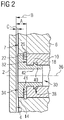
- Fig. 2 gives a more detailed view of first emergency guiding element 30 attached to piston pin 10 at first end 18 in a sectional view.
- second emergency guiding element 31 attached to second end 20 of piston pin 10.
- first end 18 of piston pin 10 is spaced apart with its piston pin outer wall 32 from inner cylinder wall 4 in a distance A.
- distance A may be typically within a range from 5 % to 10 % of an inner cylinder diameter B.
- emergency guiding element 30 is spaced apart with an integrally formed emergency guiding outer wall 34 from inner cylinder wall 4 in a distance C. Due to the attachment of emergency guiding element 30 onto end 18 of piston pin 10, distance C between inner cylinder wall 4 and emergency guiding outer wall 34 is naturally less than distance A between inner cylinder wall 4 and piston pin outer wall 32.
- Emergency guiding element 30 is configured to set distance C between emergency guiding outer wall 34 and inner cylinder wall 4 within a range from 0.1 % to 5 %, preferably within a range from 0.1 % to 4.5 %, of inner cylinder diameter B. Therefore, emergency guiding element 30 may extend more or less along a piston pin axis 36, said extend depending on several boundary conditions defined by, for example, position of circlip groove 26, length of piston pin 10, and diameter of piston skirt 7.
- emergency guiding element 30 may not necessarily extend beyond piston skirt 7. That is, depending on a desired distance C within a range from 0.1 % to 5 %, for example 1 %, of an inner cylinder diameter B and a distance between piston skirt 7 and inner cylinder wall 4 depending on the specific piston used, emergency guiding outer wall 34 may extend beyond piston skirt 7, may extend until piston skirt 7, or may extend within the confines of piston skirt 7.
- Emergency guiding element 30 is attached to piston pin 10 via a snap-fit mechanism 38 such that emergency guiding element 30 is axially fixed with respect to piston pin axis 36.
- snap-fit mechanism 38 is formed by a snap-in hook on an outer circumferential wall of a shaft section 40 of emergency guiding element 30, and a corresponding groove in an inner circumferential wall of piston pin 10.
- a vice versa arrangement of snap-in hook and corresponding groove may be also possible.
- an alternate fitting mechanism is shown.
- various other fitting mechanism exist that may be suitable to secure emergency guiding element 30 to piston pin 10.
- emergency guiding element 30 comprises a circlip recess section 41 which is configured to provide an accommodation space for circlip 22 arranged in circlip groove 26.
- Circlip recess section 41 extends from shaft section 40 towards emergency guiding outer wall 34.
- emergency guiding element 30 may have an outer diameter less than an inner diameter of circlip 22 such that emergency guiding element 30 may be attached to piston pin 10 before circlip 22 is arranged in circlip groove 26.
- emergency guiding element 30 may be attached to piston pin 10 before inserting piston pin 10 into piston bosses 14 and 16.
- emergency guiding element 30 comprises a bore 42 extending from the emergency guiding outer wall 34 through the emergency guiding element 30.
- Emergency guiding element 30 may be made of the same material as piston 6, and/or piston pin 10, for example, aluminum or steel.
- material of emergency guiding element 30 may be chosen from a group of materials providing good sliding properties such as brass, alloys, and polyamide.
- emergency guiding outer wall 34 may be coated with a sliding coating, for example, a polyamideimide based coating with added lubricant and hard particle enhancements.
- FIG. 3 a sectional view of a piston pin assembly 44 is shown.
- Sectional view of Fig. 3 lies in a plane of piston pin axis 36 and perpendicular to central axis 9.
- piston pin assembly 44 and cylinder 2 with inner cylinder wall 4 are shown.
- a piston pin assembly 44 comprises piston pin 10 with first emergency guiding element 30 attached to first end 18 of piston pin 10, and second emergency guiding element 31 attached to a second end 20 of piston pin 10 opposing the first end 18.
- first emergency guiding element 30 and second emergency guiding element 31 may be equally formed.
- emergency guiding outer wall 34 has a curved shape. Some sections of said curved shape may be adapted to a shape of inner cylinder wall 4.
- emergency guiding outer wall 34 may be at least partially shaped as a spherical cap, a spherical segment, and/or a cylindrical surface segment.
- FIG. 4 a sectional view of another piston pin assembly 44 is shown to illustrate an alternate fitting mechanism for emergency guiding elements 30, 31. Similar to Fig. 3 , sectional view of Fig. 4 lies in a plane of piston pin axis 36 and perpendicular to central axis 9, and for purpose of clarity, only piston pin assembly 44 and cylinder 2 with inner cylinder wall 4 are shown.
- the piston pin assembly 44 shown in Fig. 4 comprises an screw thread mechanism 46.
- Screw thread mechanism 46 is formed by a screw and a thread facilitating axial fixation of emergency guiding elements 30, 31 along piston pin axis 36.
- shaft section 40 of emergency guiding element 34 may comprise an external thread configured to fit into an internal thread located on an inner circumferential wall of piston pin 10.
- further applicable fitting mechanisms may exist, one of which is shrink fitting from the group of press fittings.
- Press fit (also referred to as friction fit) mechanism as used herein means fastening between two parts which is achieved by friction after the parts are pushed together.
- emergency guiding elements 30 and 31 are configured set a minimum distance C between emergency guiding outer wall 34 and inner cylinder wall 4 within a range from 0.1 % to 5 % of the inner cylinder diameter B, emergency guiding elements 30 and 31 do not come into contact with inner cylinder wall 4.
- emergency guiding outer wall 34 of emergency guiding element 30 comes into contact with inner cylinder wall 4.
- emergency guiding elements 30, 31 are configured to contact inner cylinder wall 4 with emergency guiding outer wall 34 only in case of a demolition of piston 6 as piston pin 10 is axially secured along piston axis 36 during operation of the internal combustion engine.
- Said contact between emergency guiding outer wall 34 and inner cylinder wall 4 in case of said piston demolition facilitates an emergency guidance of connecting rod 8 until the internal combustion engine finally stops.
- the emergency guidance of connecting rod 8 may reduce damage of connecting rod 8 reciprocating in cylinder 2 after demolition of piston 6.
- a tilting tendency of piston pin 6 in case of a demolition of the piston 6 may be reduced by providing emergency guiding outer wall 34 with a height.
- Height as used herein means an extend of contact face 34 along an axis parallel to central axis 9 (for example, as can be seen in Fig. 2 ).
- emergency guiding outer wall 34 may be configured to provide two emergency guiding contact points to contact inner cylinder wall 4 only in case of a demolition of piston 6.
- the two emergency guiding contact points being spaced apart from each other in a direction of central axis 9 of cylinder 2. This may be achieved, for example, by forming emergency guiding outer wall 34 as a cylindrical surface segment (which may have an annular shape due to the presence of bore 42).
- a reduced tilting tendency may further lead to an improved emergency guidance of connecting rod 8.
- a piston pin may be spaced apart with its outer wall at each end from an inner cylinder wall in a distance being typically within a range from 5 % to 10 % of an inner cylinder diameter, or greater, as already described. If a piston demolition occurs in such configurations, the clearance between the outer wall of the piston pin and the inner cylinder wall is too large resulting in an unguided reciprocation of a connecting rod attached to the piston pin for the next few strokes of the internal combustion engine until the engine finally stops. The unguided connecting rod may cause considerable damage to the cylinder wall, the cylinder as well as the entire engine, which may lead to a complete engine write-off.
- emergency guiding elements 30 and 31 may reduce damages occurring after a piston demolition, which may allow a repair of the piston demolition (for example, by replacement) in a cost effective manner as a complete engine write-off due to an unguided connecting rod considerably increasing the damage may be prevented.
- emergency guiding elements 30, 31 may be applicable in internal combustion engines including a piston connected to a connecting rod via a piston pin.
- Said internal combustion engine may include features not shown, such as air systems, cooling systems, peripheries, drivetrain components, etc.
- internal combustion engine may be of any size, with any number of cylinders, and in any configuration (e.g., "V," in-line, radial, etc.).
- internal combustion engine may be used to power any machine or other device, including, but not limited to, locomotive applications, on-highway trucks or vehicles, off-highway trucks or machines, earth moving equipment, generators, aerospace applications, marine applications, offshore applications, pumps, stationary equipment, or other engine powered applications.
- emergency guiding elements 30, 31 may be applicable in any piston machine including, but not limited to, piston compressors and piston pumps, to reduce damages caused by a piston demolition.
Landscapes
- Engineering & Computer Science (AREA)
- General Engineering & Computer Science (AREA)
- Chemical & Material Sciences (AREA)
- Combustion & Propulsion (AREA)
- Mechanical Engineering (AREA)
- Pistons, Piston Rings, And Cylinders (AREA)
Claims (10)
- Kolbeneinheit (33), die konfiguriert ist, um in einem Zylinder (2) mit einer inneren Zylinderwand (4) angeordnet zu sein, umfassend:einen Kolben (6), der konfiguriert ist, um reziprok innerhalb des Zylinders (2) angeordnet zu sein;eine Verbindungsstange (8),einen ersten Sicherungsring (22),einen zweiten Sicherungsring (24); undeine Kolbenbolzeneinheit (44), die einschließteinen Kolbenbolzen (10) zur Verbindung der Verbindungsstange (8) und des Kolbens (6), wobei der Kolbenbolzen (10) ein erstes Ende (18) und ein zweites Ende (20) aufweist, das dem ersten Ende (18) gegenüberliegt,ein erstes Notführungselement (30), das an dem ersten Ende (18) des Kolbenbolzens (10) befestigt ist, wobei das erste Notführungselement (30) einstückig mit einer ersten Notführungs-Außenwand (34) gebildet ist, um der inneren Zylinderwand (4) gegenüber zu liegen, und um mit der inneren Zylinderwand (4) nur für den Fall einer Zerstörung des Kolbens (6) in Kontakt zu kommen, undein zweites Notführungselement (31), das an dem zweiten Ende (20) des Kolbenbolzens (10) befestigt ist, wobei das zweite Notführungselement (31) mit einer zweiten Notführungs-Außenwand (34) gebildet ist, um der inneren Zylinderwand (4) gegenüber zu liegen, und um mit der inneren Zylinderwand (4) nur für den Fall einer Zerstörung des Kolbens (6) in Kontakt zu kommen, wobei das erste Notführungselement (30) und das zweite Notführungselement (31) einschließeneine Bohrung (42), die sich von der Notführungs-Außenwand (34) durch das Führungselement (30, 31) erstreckt, undeinen Sicherungsring-Aussparungsabschnitt (41), der konfiguriert ist, um einen Aufnahmeraum für den ersten Sicherungsring (22) und den zweiten Sicherungsring (24) bereitzustellen, um den Kolbenbolzen (10) axial im Kolben (6) zu fixieren.
- Kolbeneinheit (44) nach Anspruch 1, wobei der Kolbenbolzen (10) als ein hohler Kolbenbolzen gebildet ist und das erste Notführungselement (30) und das zweite Notführungselement (31) aneinander mit Hilfe eines Schrauben-Gewinde-Mechanismus (46) befestigt sind, der sich durch den hohlen Kolbenbolzen (10) erstreckt.
- Kolbeneinheit (44) nach Anspruch 1 oder 2, wobei die Notführungs-Außenwand (34) eine gekrümmte Form aufweist.
- Kolbeneinheit (44) nach einem der vorstehenden Ansprüche, wobei sich der Zylinder (2) entlang einer zentralen Achse (9) erstreckt und die Notführungs-Außenwand (34) konfiguriert ist, um zwei Notführungs-Kontaktpunkte bereitzustellen, um mit der inneren Zylinderwand (4) nur für den Fall einer Zerstörung des Kolbens (6) in Kontakt zu kommen, wobei die zwei Notführungs-Kontaktpunkte voneinander in einer Richtung der zentralen Achse (9) beabstandet sind.
- Kolbeneinheit (44) nach einem der vorstehenden Ansprüche, wobei die Notführungs-Außenwand (34) mindestens teilweise als eine sphärische Kappe, ein sphärisches Segment und/oder ein zylindrisches Oberflächensegment gebildet ist.
- Kolbeneinheit (44) nach einem der vorstehenden Ansprüche, wobei das Notführungselement (30, 31) konfiguriert ist, um an dem Ende (18, 20) des Kolbenbolzens (10) durch einen Schnappbefestigungsmechanismus (38) befestigt zu sein.
- Kolbeneinheit (44) nach einem der vorstehenden Ansprüche, wobei das Notführungselement (30; 31) konfiguriert ist, um an dem Ende (18, 20) des Kolbenbolzens (10) durch einen Schrauben-Gewinde-Mechanismus (46) befestigt zu sein.
- Kolbeneinheit (44) nach einem der vorstehenden Ansprüche, wobei das Notführungselement, (30; 31) konfiguriert ist, um an dem Ende (18, 20) des Kolbenbolzens (10) durch einen Presspassmechanismus befestigt zu sein.
- Kolbeneinheit (44) nach einem der vorstehenden Ansprüche, wobei das Notführungselement (30, 31) aus Messing, Legierung, Stahl, Aluminium oder Polyamid hergestellt ist; und/oder
wobei die Notführungs-Außenwand (34) mit einer Gleitbeschichtung beschichtet ist. - Zylinder- und Kolbeneinheit eines Verbrennungsmotors, wobei die Zylinder- und Kolbeneinheit umfasst:einen Zylinder (2), der einen inneren Zylinderdurchmesser (B) und eine innere Zylinderwand (4) aufweist; undeine Kolbeneinheit (44) nach einem der vorstehenden Ansprüche, wobeidas erste Notführungselement, (30) konfiguriert ist, um einen minimalen Abstand (C) zwischen der ersten Notführungs-Außenwand (34) und der inneren Zylinderwand (4) innerhalb eines Bereichs von 0,1 % bis 5% des inneren Zylinderdurchmessers (B) festzusetzen; unddas zweite Notführungselement (30) konfiguriert ist, um einen minimalen Abstand (C) zwischen der zweiten Notführungs-Außenwand (34) und der inneren Zylinderwand (4) innerhalb eines Bereichs von 0,1% bis 5% des inneren Zylinderdurchmessers (B) festzusetzen.
Priority Applications (2)
| Application Number | Priority Date | Filing Date | Title |
|---|---|---|---|
| EP12198554.3A EP2746622B1 (de) | 2012-12-20 | 2012-12-20 | Notführungselement für einen Kolbenbolzen |
| PCT/EP2013/003872 WO2014095075A1 (en) | 2012-12-20 | 2013-12-19 | Emergency guiding element for piston pin |
Applications Claiming Priority (1)
| Application Number | Priority Date | Filing Date | Title |
|---|---|---|---|
| EP12198554.3A EP2746622B1 (de) | 2012-12-20 | 2012-12-20 | Notführungselement für einen Kolbenbolzen |
Publications (2)
| Publication Number | Publication Date |
|---|---|
| EP2746622A1 EP2746622A1 (de) | 2014-06-25 |
| EP2746622B1 true EP2746622B1 (de) | 2018-03-28 |
Family
ID=47559173
Family Applications (1)
| Application Number | Title | Priority Date | Filing Date |
|---|---|---|---|
| EP12198554.3A Active EP2746622B1 (de) | 2012-12-20 | 2012-12-20 | Notführungselement für einen Kolbenbolzen |
Country Status (2)
| Country | Link |
|---|---|
| EP (1) | EP2746622B1 (de) |
| WO (1) | WO2014095075A1 (de) |
Families Citing this family (2)
| Publication number | Priority date | Publication date | Assignee | Title |
|---|---|---|---|---|
| JP6274190B2 (ja) * | 2015-11-24 | 2018-02-07 | トヨタ自動車株式会社 | 内燃機関およびピストンピン |
| US11835135B1 (en) * | 2022-06-28 | 2023-12-05 | Deltahawk Engines, Inc. | Piston assembly with wrist pin cap |
Citations (1)
| Publication number | Priority date | Publication date | Assignee | Title |
|---|---|---|---|---|
| US4011797A (en) * | 1973-07-19 | 1977-03-15 | Dampers Societe Anonyme | Oil-cooled piston for a heat engine |
Family Cites Families (9)
| Publication number | Priority date | Publication date | Assignee | Title |
|---|---|---|---|---|
| DE430514C (de) * | 1925-10-06 | 1926-06-19 | Elektronmetall G M B H Fa | Sicherung fuer Kolbenbolzen von Verbrennungskraftmaschinen |
| FR639952A (fr) * | 1927-08-24 | 1928-07-03 | Dispositif de montage des axes de pistons | |
| DE1676810U (de) * | 1952-10-24 | 1954-05-26 | Maschf Augsburg Nuernberg Ag | Treibstangenbefestigung bei leichtmetallkolben mit schwimmendem kolbenbolzen von mit hohen zuenddruecken arbeitenden brennkraftmaschinen. |
| US3136306A (en) * | 1961-04-20 | 1964-06-09 | Stevens Inst Technology | Piston for a high performance internal combustion engine |
| US4640641A (en) * | 1984-07-25 | 1987-02-03 | Teledyne Continental Motors | Piston pin construction and method for forming same |
| DE3642525A1 (de) * | 1986-12-12 | 1988-06-23 | Mahle Gmbh | Leichtmetall-hubkolben fuer verbrennungsmotoren mit leichtmetall-zylindern |
| US5289758A (en) * | 1992-05-05 | 1994-03-01 | Caterpillar Inc. | Pin plugs for use in a piston assembly |
| US6520069B2 (en) | 2001-01-29 | 2003-02-18 | Detroit Diesel Corporation | Piston pin for internal combustion engine |
| DE102006035178A1 (de) | 2006-07-29 | 2007-08-09 | Ks Kolbenschmidt Gmbh | Verschlusselement für das Kolbenbolzenloch eines Kolbenbolzens eines Kolbens einer Zweitakt-Brennkraftmaschine |
-
2012
- 2012-12-20 EP EP12198554.3A patent/EP2746622B1/de active Active
-
2013
- 2013-12-19 WO PCT/EP2013/003872 patent/WO2014095075A1/en not_active Ceased
Patent Citations (1)
| Publication number | Priority date | Publication date | Assignee | Title |
|---|---|---|---|---|
| US4011797A (en) * | 1973-07-19 | 1977-03-15 | Dampers Societe Anonyme | Oil-cooled piston for a heat engine |
Also Published As
| Publication number | Publication date |
|---|---|
| EP2746622A1 (de) | 2014-06-25 |
| WO2014095075A1 (en) | 2014-06-26 |
Similar Documents
| Publication | Publication Date | Title |
|---|---|---|
| CN113330206B (zh) | 具有下衬套支承件的用于发动机气缸的衬套 | |
| US10119613B2 (en) | Wrist pin and method of reducing wear between members thereof, connecting rod, piston and methods of constructing same | |
| KR101927903B1 (ko) | 내연기관용 피스톤 | |
| US20150211438A1 (en) | Piston with oil reservoir | |
| EP2815155B1 (de) | Kolbenring für verbrennungsmotor | |
| EP2746622A1 (de) | Notführungselement für einen Kolbenbolzen | |
| WO2013123301A1 (en) | Piston ring for an internal combustion engine | |
| CN105179129B (zh) | 专门用于燃料喷射泵的凸轮从动辊装置 | |
| US7975601B2 (en) | Engine cylinder liner | |
| EP2746623B1 (de) | Kolbenbolzen mit Notführungsfähigkeit | |
| CN110392772A (zh) | 内燃发动机 | |
| US20090101004A1 (en) | Two part piston for an internal combustion engine | |
| EP4039977A1 (de) | Verdichter | |
| CN108271404A (zh) | 优化的毂支撑 | |
| US6463903B1 (en) | Piston assembly for free piston internal combustion engine | |
| US12523295B2 (en) | Connecting rod guide | |
| US11035352B2 (en) | Method and system for enhancing performance in a reciprocating compressor | |
| US20130213221A1 (en) | Piston ring for an internal combustion engine | |
| US11835135B1 (en) | Piston assembly with wrist pin cap | |
| CN209228755U (zh) | 基于螺栓安装的液压油缸 | |
| RU2500941C2 (ru) | Способ осевой фиксации шатуна двигателя внутреннего сгорания | |
| KR20070066862A (ko) | 왕복 내연 기관 | |
| WO2023066440A1 (en) | A connecting rod and a piston for a high-pressure piston pump, and a high-pressure piston pump for pumping fuel | |
| KR20090061988A (ko) | 내연기관의 커넥팅 로드 | |
| KR20070062170A (ko) | 피스톤 핀의 조립구조 |
Legal Events
| Date | Code | Title | Description |
|---|---|---|---|
| PUAI | Public reference made under article 153(3) epc to a published international application that has entered the european phase |
Free format text: ORIGINAL CODE: 0009012 |
|
| 17P | Request for examination filed |
Effective date: 20121220 |
|
| AK | Designated contracting states |
Kind code of ref document: A1 Designated state(s): AL AT BE BG CH CY CZ DE DK EE ES FI FR GB GR HR HU IE IS IT LI LT LU LV MC MK MT NL NO PL PT RO RS SE SI SK SM TR |
|
| AX | Request for extension of the european patent |
Extension state: BA ME |
|
| RAP1 | Party data changed (applicant data changed or rights of an application transferred) |
Owner name: CATERPILLAR ENERGY SOLUTIONS GMBH |
|
| R17P | Request for examination filed (corrected) |
Effective date: 20141222 |
|
| RBV | Designated contracting states (corrected) |
Designated state(s): AL AT BE BG CH CY CZ DE DK EE ES FI FR GB GR HR HU IE IS IT LI LT LU LV MC MK MT NL NO PL PT RO RS SE SI SK SM TR |
|
| 17Q | First examination report despatched |
Effective date: 20161028 |
|
| GRAP | Despatch of communication of intention to grant a patent |
Free format text: ORIGINAL CODE: EPIDOSNIGR1 |
|
| INTG | Intention to grant announced |
Effective date: 20171009 |
|
| GRAS | Grant fee paid |
Free format text: ORIGINAL CODE: EPIDOSNIGR3 |
|
| GRAA | (expected) grant |
Free format text: ORIGINAL CODE: 0009210 |
|
| AK | Designated contracting states |
Kind code of ref document: B1 Designated state(s): AL AT BE BG CH CY CZ DE DK EE ES FI FR GB GR HR HU IE IS IT LI LT LU LV MC MK MT NL NO PL PT RO RS SE SI SK SM TR |
|
| REG | Reference to a national code |
Ref country code: GB Ref legal event code: FG4D |
|
| REG | Reference to a national code |
Ref country code: CH Ref legal event code: EP |
|
| REG | Reference to a national code |
Ref country code: AT Ref legal event code: REF Ref document number: 983746 Country of ref document: AT Kind code of ref document: T Effective date: 20180415 |
|
| REG | Reference to a national code |
Ref country code: IE Ref legal event code: FG4D |
|
| REG | Reference to a national code |
Ref country code: DE Ref legal event code: R096 Ref document number: 602012044431 Country of ref document: DE |
|
| PG25 | Lapsed in a contracting state [announced via postgrant information from national office to epo] |
Ref country code: HR Free format text: LAPSE BECAUSE OF FAILURE TO SUBMIT A TRANSLATION OF THE DESCRIPTION OR TO PAY THE FEE WITHIN THE PRESCRIBED TIME-LIMIT Effective date: 20180328 Ref country code: NO Free format text: LAPSE BECAUSE OF FAILURE TO SUBMIT A TRANSLATION OF THE DESCRIPTION OR TO PAY THE FEE WITHIN THE PRESCRIBED TIME-LIMIT Effective date: 20180628 Ref country code: LT Free format text: LAPSE BECAUSE OF FAILURE TO SUBMIT A TRANSLATION OF THE DESCRIPTION OR TO PAY THE FEE WITHIN THE PRESCRIBED TIME-LIMIT Effective date: 20180328 Ref country code: FI Free format text: LAPSE BECAUSE OF FAILURE TO SUBMIT A TRANSLATION OF THE DESCRIPTION OR TO PAY THE FEE WITHIN THE PRESCRIBED TIME-LIMIT Effective date: 20180328 |
|
| REG | Reference to a national code |
Ref country code: NL Ref legal event code: MP Effective date: 20180328 |
|
| REG | Reference to a national code |
Ref country code: LT Ref legal event code: MG4D |
|
| PG25 | Lapsed in a contracting state [announced via postgrant information from national office to epo] |
Ref country code: LV Free format text: LAPSE BECAUSE OF FAILURE TO SUBMIT A TRANSLATION OF THE DESCRIPTION OR TO PAY THE FEE WITHIN THE PRESCRIBED TIME-LIMIT Effective date: 20180328 Ref country code: SE Free format text: LAPSE BECAUSE OF FAILURE TO SUBMIT A TRANSLATION OF THE DESCRIPTION OR TO PAY THE FEE WITHIN THE PRESCRIBED TIME-LIMIT Effective date: 20180328 Ref country code: GR Free format text: LAPSE BECAUSE OF FAILURE TO SUBMIT A TRANSLATION OF THE DESCRIPTION OR TO PAY THE FEE WITHIN THE PRESCRIBED TIME-LIMIT Effective date: 20180629 Ref country code: RS Free format text: LAPSE BECAUSE OF FAILURE TO SUBMIT A TRANSLATION OF THE DESCRIPTION OR TO PAY THE FEE WITHIN THE PRESCRIBED TIME-LIMIT Effective date: 20180328 Ref country code: BG Free format text: LAPSE BECAUSE OF FAILURE TO SUBMIT A TRANSLATION OF THE DESCRIPTION OR TO PAY THE FEE WITHIN THE PRESCRIBED TIME-LIMIT Effective date: 20180628 |
|
| PG25 | Lapsed in a contracting state [announced via postgrant information from national office to epo] |
Ref country code: RO Free format text: LAPSE BECAUSE OF FAILURE TO SUBMIT A TRANSLATION OF THE DESCRIPTION OR TO PAY THE FEE WITHIN THE PRESCRIBED TIME-LIMIT Effective date: 20180328 Ref country code: IT Free format text: LAPSE BECAUSE OF FAILURE TO SUBMIT A TRANSLATION OF THE DESCRIPTION OR TO PAY THE FEE WITHIN THE PRESCRIBED TIME-LIMIT Effective date: 20180328 Ref country code: EE Free format text: LAPSE BECAUSE OF FAILURE TO SUBMIT A TRANSLATION OF THE DESCRIPTION OR TO PAY THE FEE WITHIN THE PRESCRIBED TIME-LIMIT Effective date: 20180328 Ref country code: AL Free format text: LAPSE BECAUSE OF FAILURE TO SUBMIT A TRANSLATION OF THE DESCRIPTION OR TO PAY THE FEE WITHIN THE PRESCRIBED TIME-LIMIT Effective date: 20180328 Ref country code: NL Free format text: LAPSE BECAUSE OF FAILURE TO SUBMIT A TRANSLATION OF THE DESCRIPTION OR TO PAY THE FEE WITHIN THE PRESCRIBED TIME-LIMIT Effective date: 20180328 Ref country code: PL Free format text: LAPSE BECAUSE OF FAILURE TO SUBMIT A TRANSLATION OF THE DESCRIPTION OR TO PAY THE FEE WITHIN THE PRESCRIBED TIME-LIMIT Effective date: 20180328 Ref country code: ES Free format text: LAPSE BECAUSE OF FAILURE TO SUBMIT A TRANSLATION OF THE DESCRIPTION OR TO PAY THE FEE WITHIN THE PRESCRIBED TIME-LIMIT Effective date: 20180328 |
|
| PG25 | Lapsed in a contracting state [announced via postgrant information from national office to epo] |
Ref country code: CZ Free format text: LAPSE BECAUSE OF FAILURE TO SUBMIT A TRANSLATION OF THE DESCRIPTION OR TO PAY THE FEE WITHIN THE PRESCRIBED TIME-LIMIT Effective date: 20180328 Ref country code: SK Free format text: LAPSE BECAUSE OF FAILURE TO SUBMIT A TRANSLATION OF THE DESCRIPTION OR TO PAY THE FEE WITHIN THE PRESCRIBED TIME-LIMIT Effective date: 20180328 Ref country code: SM Free format text: LAPSE BECAUSE OF FAILURE TO SUBMIT A TRANSLATION OF THE DESCRIPTION OR TO PAY THE FEE WITHIN THE PRESCRIBED TIME-LIMIT Effective date: 20180328 |
|
| REG | Reference to a national code |
Ref country code: AT Ref legal event code: MK05 Ref document number: 983746 Country of ref document: AT Kind code of ref document: T Effective date: 20180328 |
|
| PG25 | Lapsed in a contracting state [announced via postgrant information from national office to epo] |
Ref country code: PT Free format text: LAPSE BECAUSE OF FAILURE TO SUBMIT A TRANSLATION OF THE DESCRIPTION OR TO PAY THE FEE WITHIN THE PRESCRIBED TIME-LIMIT Effective date: 20180730 |
|
| REG | Reference to a national code |
Ref country code: DE Ref legal event code: R097 Ref document number: 602012044431 Country of ref document: DE |
|
| PG25 | Lapsed in a contracting state [announced via postgrant information from national office to epo] |
Ref country code: DK Free format text: LAPSE BECAUSE OF FAILURE TO SUBMIT A TRANSLATION OF THE DESCRIPTION OR TO PAY THE FEE WITHIN THE PRESCRIBED TIME-LIMIT Effective date: 20180328 Ref country code: AT Free format text: LAPSE BECAUSE OF FAILURE TO SUBMIT A TRANSLATION OF THE DESCRIPTION OR TO PAY THE FEE WITHIN THE PRESCRIBED TIME-LIMIT Effective date: 20180328 |
|
| PLBE | No opposition filed within time limit |
Free format text: ORIGINAL CODE: 0009261 |
|
| STAA | Information on the status of an ep patent application or granted ep patent |
Free format text: STATUS: NO OPPOSITION FILED WITHIN TIME LIMIT |
|
| 26N | No opposition filed |
Effective date: 20190103 |
|
| PG25 | Lapsed in a contracting state [announced via postgrant information from national office to epo] |
Ref country code: SI Free format text: LAPSE BECAUSE OF FAILURE TO SUBMIT A TRANSLATION OF THE DESCRIPTION OR TO PAY THE FEE WITHIN THE PRESCRIBED TIME-LIMIT Effective date: 20180328 |
|
| REG | Reference to a national code |
Ref country code: CH Ref legal event code: PL |
|
| PG25 | Lapsed in a contracting state [announced via postgrant information from national office to epo] |
Ref country code: LU Free format text: LAPSE BECAUSE OF NON-PAYMENT OF DUE FEES Effective date: 20181220 Ref country code: MC Free format text: LAPSE BECAUSE OF FAILURE TO SUBMIT A TRANSLATION OF THE DESCRIPTION OR TO PAY THE FEE WITHIN THE PRESCRIBED TIME-LIMIT Effective date: 20180328 |
|
| REG | Reference to a national code |
Ref country code: IE Ref legal event code: MM4A |
|
| REG | Reference to a national code |
Ref country code: BE Ref legal event code: MM Effective date: 20181231 |
|
| PG25 | Lapsed in a contracting state [announced via postgrant information from national office to epo] |
Ref country code: IE Free format text: LAPSE BECAUSE OF NON-PAYMENT OF DUE FEES Effective date: 20181220 |
|
| PG25 | Lapsed in a contracting state [announced via postgrant information from national office to epo] |
Ref country code: BE Free format text: LAPSE BECAUSE OF NON-PAYMENT OF DUE FEES Effective date: 20181231 |
|
| PG25 | Lapsed in a contracting state [announced via postgrant information from national office to epo] |
Ref country code: CH Free format text: LAPSE BECAUSE OF NON-PAYMENT OF DUE FEES Effective date: 20181231 Ref country code: LI Free format text: LAPSE BECAUSE OF NON-PAYMENT OF DUE FEES Effective date: 20181231 |
|
| PG25 | Lapsed in a contracting state [announced via postgrant information from national office to epo] |
Ref country code: MT Free format text: LAPSE BECAUSE OF NON-PAYMENT OF DUE FEES Effective date: 20181220 |
|
| PG25 | Lapsed in a contracting state [announced via postgrant information from national office to epo] |
Ref country code: TR Free format text: LAPSE BECAUSE OF FAILURE TO SUBMIT A TRANSLATION OF THE DESCRIPTION OR TO PAY THE FEE WITHIN THE PRESCRIBED TIME-LIMIT Effective date: 20180328 |
|
| PG25 | Lapsed in a contracting state [announced via postgrant information from national office to epo] |
Ref country code: MK Free format text: LAPSE BECAUSE OF NON-PAYMENT OF DUE FEES Effective date: 20180328 Ref country code: HU Free format text: LAPSE BECAUSE OF FAILURE TO SUBMIT A TRANSLATION OF THE DESCRIPTION OR TO PAY THE FEE WITHIN THE PRESCRIBED TIME-LIMIT; INVALID AB INITIO Effective date: 20121220 Ref country code: CY Free format text: LAPSE BECAUSE OF FAILURE TO SUBMIT A TRANSLATION OF THE DESCRIPTION OR TO PAY THE FEE WITHIN THE PRESCRIBED TIME-LIMIT Effective date: 20180328 |
|
| PG25 | Lapsed in a contracting state [announced via postgrant information from national office to epo] |
Ref country code: IS Free format text: LAPSE BECAUSE OF FAILURE TO SUBMIT A TRANSLATION OF THE DESCRIPTION OR TO PAY THE FEE WITHIN THE PRESCRIBED TIME-LIMIT Effective date: 20180728 |
|
| PGFP | Annual fee paid to national office [announced via postgrant information from national office to epo] |
Ref country code: FR Payment date: 20211118 Year of fee payment: 10 |
|
| PGFP | Annual fee paid to national office [announced via postgrant information from national office to epo] |
Ref country code: GB Payment date: 20221116 Year of fee payment: 11 |
|
| P01 | Opt-out of the competence of the unified patent court (upc) registered |
Effective date: 20230517 |
|
| PG25 | Lapsed in a contracting state [announced via postgrant information from national office to epo] |
Ref country code: FR Free format text: LAPSE BECAUSE OF NON-PAYMENT OF DUE FEES Effective date: 20221231 |
|
| GBPC | Gb: european patent ceased through non-payment of renewal fee |
Effective date: 20231220 |
|
| PG25 | Lapsed in a contracting state [announced via postgrant information from national office to epo] |
Ref country code: GB Free format text: LAPSE BECAUSE OF NON-PAYMENT OF DUE FEES Effective date: 20231220 |
|
| PG25 | Lapsed in a contracting state [announced via postgrant information from national office to epo] |
Ref country code: GB Free format text: LAPSE BECAUSE OF NON-PAYMENT OF DUE FEES Effective date: 20231220 |
|
| PGFP | Annual fee paid to national office [announced via postgrant information from national office to epo] |
Ref country code: DE Payment date: 20251126 Year of fee payment: 14 |