EP2746212B1 - Method for tracking the rotational speed of a crane drive and crane drive - Google Patents
Method for tracking the rotational speed of a crane drive and crane drive Download PDFInfo
- Publication number
- EP2746212B1 EP2746212B1 EP13006069.2A EP13006069A EP2746212B1 EP 2746212 B1 EP2746212 B1 EP 2746212B1 EP 13006069 A EP13006069 A EP 13006069A EP 2746212 B1 EP2746212 B1 EP 2746212B1
- Authority
- EP
- European Patent Office
- Prior art keywords
- crane
- speed
- mot
- control
- volume flow
- Prior art date
- Legal status (The legal status is an assumption and is not a legal conclusion. Google has not performed a legal analysis and makes no representation as to the accuracy of the status listed.)
- Active
Links
- 238000000034 method Methods 0.000 title claims description 33
- 238000006073 displacement reaction Methods 0.000 claims description 42
- 230000007613 environmental effect Effects 0.000 claims description 4
- 230000003111 delayed effect Effects 0.000 claims description 2
- 238000010586 diagram Methods 0.000 description 15
- 230000005540 biological transmission Effects 0.000 description 10
- 230000009467 reduction Effects 0.000 description 7
- 239000000446 fuel Substances 0.000 description 6
- 230000004044 response Effects 0.000 description 6
- 230000001419 dependent effect Effects 0.000 description 5
- 230000008569 process Effects 0.000 description 5
- 230000001105 regulatory effect Effects 0.000 description 5
- 238000002485 combustion reaction Methods 0.000 description 4
- 230000001276 controlling effect Effects 0.000 description 4
- 238000004364 calculation method Methods 0.000 description 3
- 230000007246 mechanism Effects 0.000 description 3
- 230000007935 neutral effect Effects 0.000 description 3
- 238000013459 approach Methods 0.000 description 2
- 238000004146 energy storage Methods 0.000 description 2
- 238000005259 measurement Methods 0.000 description 2
- 238000012546 transfer Methods 0.000 description 2
- 238000013519 translation Methods 0.000 description 2
- 238000010521 absorption reaction Methods 0.000 description 1
- 230000001133 acceleration Effects 0.000 description 1
- 230000008859 change Effects 0.000 description 1
- 230000003252 repetitive effect Effects 0.000 description 1
Images


Classifications
-
- B—PERFORMING OPERATIONS; TRANSPORTING
- B66—HOISTING; LIFTING; HAULING
- B66C—CRANES; LOAD-ENGAGING ELEMENTS OR DEVICES FOR CRANES, CAPSTANS, WINCHES, OR TACKLES
- B66C13/00—Other constructional features or details
- B66C13/18—Control systems or devices
- B66C13/20—Control systems or devices for non-electric drives
-
- F—MECHANICAL ENGINEERING; LIGHTING; HEATING; WEAPONS; BLASTING
- F15—FLUID-PRESSURE ACTUATORS; HYDRAULICS OR PNEUMATICS IN GENERAL
- F15B—SYSTEMS ACTING BY MEANS OF FLUIDS IN GENERAL; FLUID-PRESSURE ACTUATORS, e.g. SERVOMOTORS; DETAILS OF FLUID-PRESSURE SYSTEMS, NOT OTHERWISE PROVIDED FOR
- F15B21/00—Common features of fluid actuator systems; Fluid-pressure actuator systems or details thereof, not covered by any other group of this subclass
- F15B21/08—Servomotor systems incorporating electrically operated control means
- F15B21/082—Servomotor systems incorporating electrically operated control means with different modes
Definitions
- the invention relates to a method for speed tracking of a hydraulic crane drive with at least one hydraulic consumer, for example a hydraulic motor which is fed via at least one adjustable hydraulic pump, and which is driven by the drive unit of the crane at least one variable.
- Cranes in particular mobile cranes, have a hydraulic system for driving the various crane functions.
- This hydraulic system is supplied by one or more hydraulic pumps, which are supplied at least partially via a central drive unit of the crane, in particular an internal combustion engine.
- the delivery volume of the individual hydraulic pumps depends on the input speed of the engine output. The larger the volume pumped, the faster the speed of movement of each hydraulic consumer powered by the pump to perform different crane functions.
- the driver of the crane does not know the required engine speed necessary for the proper operation of the crane hydraulics with the desired speed of movement necessary is. Due to this ignorance, the drivers run the drive unit at high speed to ensure sufficient reserves for setting any movement speed. In many cases, however, a much lower speed is sufficient. In addition to excessive fuel consumption and high noise emission, this also leads to unnecessarily heavy wear on the drive unit.
- Object of the present invention is therefore to optimize the fuel consumption of the crane while reducing noise emissions.
- the hydraulic crane drive consists of at least one hydraulic consumer, in particular a hydraulic motor, for carrying out a specific crane function. At least one consumer serves, for example, as a rotary drive of the superstructure or to drive a winch. Furthermore, at least one hydraulic variable-displacement pump is provided, which supplies the at least one hydraulic consumer with an adjustable volume flow. The at least one variable displacement pump is driven by at least one central drive unit of the crane.
- the speed of the drive unit and the pivot angle of the at least one variable in dependence on the requested volume flow for at least one of the consumers and in dependence of another crane-specific Parameters are controlled or regulated by the crane control and that the target speed is calculated by the crane control from the requested volume flow.
- the calculation is carried out dynamically at runtime as a function of the current requested volume flow.
- the influence of the crane control on the speed tracking can also be overridden at any time by a corresponding user input.
- a conceivable user input represents the operation of the accelerator pedal.
- the speed of the drive unit is increased according to the invention until the determined from the current speed of the drive unit or from the speed of the at least one variable volume flow corresponds to the requested volume flow or converges against it.
- the volume flow determined from the speed is calculated as a function of individual specific pump parameters. In this way, depending on the known speed at which the drive unit drives the at least one variable displacement pump, a theoretically possible volume flow at the outlet of the variable displacement pump can be concluded. However, this assumption is only valid as long as the at least one variable displacement pump or the powered consumer works without load.
- the drive unit may preferably be an internal combustion engine, in particular a diesel engine, or else an electric or hybrid engine.
- the process execution is independent of the desired system structure of the hydraulics.
- the one or more consumers and the at least one pump can be connected as an open or closed hydraulic circuit.
- the desired movement speed of the crane actuator or hydraulic consumer is determined by user input. Based on the user input, the crane control determines the energy required for this purpose, ie the required volume flow, which must be provided by the at least one variable displacement pump to the hydraulic consumer or consumers.
- the crane control is responsible for setting the desired movement speed. For this purpose, controls or regulates the crane control, if necessary, the drive unit of the crane and at least one adjustable hydraulic pump.
- Another crane-specific parameters for the control or regulation of the drive unit can be taken into account.
- Possible parameters represent, for example, one or more values representing the height level above normal zero of the crane and / or a charging process of an energy store and / or the efficiencies of all or at least a portion of the consumers and / or at least one environmental condition, in particular the ambient temperature of the crane, and / or characterize a direct specification, in particular target speed specification of the crane operator.
- Environmental conditions such as external pressure and ambient temperature, may affect the working conditions of the hydraulic system. Charging an energy storage may require a higher engine speed.
- At least one or at least some of these values can be taken into account by the crane control for the control and / or regulation of the rotational speed or the swivel angle of at least one variable displacement pump.
- the consideration takes place either additionally or alternatively requested volume flow for at least one consumer
- Control of the speed is understood to mean both an increase and a reduction in the current speed. The same applies to the control or regulation of the swivel angle. Depending on the requested volume flow and / or a further parameter, this can optionally be reduced or increased.
- At least one proportionally controllable directional seat valve is provided, which is connected between at least one variable displacement pump and at least one consumer.
- at least one variable displacement pump is connected between at least one variable displacement pump and at least one consumer.
- a signal for controlling at least one valve is generated.
- a volume flow is established which the valve can pass to the hydraulic consumer.
- the crane control can calculate this volume flow.
- the directional seat valve is adjusted for example via a suitable adjusting mechanism, in particular an electromagnet.
- the requested volume flow is adjusted via at least one operating lever of the crane.
- One or more control levers are provided for example in the crane cab. By operating the lever, ie deflection of the lever from the neutral position to the end position, the crane operator can set the desired volume flow. For example, at least one operating lever can be deflected from a middle position, ie neutral position, in four directions. In this case, the lever position in conjunction with one or more reductions represents the desired volume flow. Due to various operations, for example, an approach to a shutdown limit of the working area limitation, the crane control determines so-called reductions. These are usually in the range between 0 to 100%, with an amount of 100% corresponds to no reduction. The specification by the operating lever is charged with such a reduction and determines a final reduced flow rate.
- the signals of at least one control lever can be transmitted either via a BUS connection or alternatively via a radio link to the crane control.
- the crane control To control the speed of the drive unit, the crane control must determine a corresponding desired speed as a function of the requested volume flow. The determination can be made using a map.
- the map contains torque and / or speed curves with respective fuel consumption of the drive unit.
- Such a map is ideally stored in the crane control. For example, the relationship between hydraulic pressure and engine speed and / or for at least one characteristic field of the relationship between torque and speed is shown for at least one characteristic field. For each value of one of the characteristic fields, the associated fuel consumption, in particular in kilograms per hour, shown.
- the volume flow determined from the instantaneous engine power is adjusted to the requested volume flow by controlling the rotational speed.
- the volume flow determined from the instantaneous engine power can optionally or alternatively be determined from the applied pump pressure at the outlet of the at least one variable displacement pump.
- a corresponding sensor for detecting the output pressure can be used.
- a volume flow is determined from the instantaneous engine power or the instantaneous pump output pressure.
- This calculated volume flow is fed as input value to a controlled system, which adjusts the calculated volume flow to the requested volume flow by controlling the speed of the drive unit.
- a controller for example an I controller, wherein the requested volumetric flow rate is used as the nominal value and the volumetric flow rate determined from the instantaneous engine power and the instantaneous pump pressure is used as actual value.
- the crane control system adapts the acceleration and / or deceleration ramps of the rotational speed of the drive assembly individually and load-dependent.
- the readjustment time of the controller used can be used to control the speed with which the output signal of the controller used follows the input signal. This time is dynamically adjustable.
- the crane control summarizes the individual requested volume flows of the respective consumers to a total demand.
- the method described above is then applied to the specific total demand, the total demand in this case corresponding to the requested volume flow. If the determined total requirement exceeds the maximum possible delivery volume of the at least one variable displacement pump, then the crane control system must adjust the maximum possible delivery volume to the individual delivery split hydraulic consumers. In particular, the distribution is proportional to the respective volume flow demand of the individual consumers.
- the mechanical drive train is disengaged if the crane control detects idling.
- the crane control can wait for a certain time interval after determining an idle operation until it disengages the drive train of the superstructure as close as possible to the drive unit.
- the defined time interval may, for example, be in the range of one minute. This reduces the losses in mechanical drive shafts and transmissions.
- This solution proves to be particularly advantageous in a single-engine crane in which the superstructure is driven by the undercarriage engine.
- the manual transmission is mounted very close to the engine, which serves for driving as well as for crane operation.
- the entire drive train to the superstructure with all losses (angle gear) can be decoupled and yet the complete power is available after about one to two seconds again for crane operation.
- automatic shutdown of the power pack by the controller may be considered.
- the invention further relates to a hydraulic crane drive with a crane control for carrying out the method according to the invention or for carrying out an advantageous embodiment of the method according to the invention.
- the crane drive or the crane control has corresponding means for carrying out the method.
- the invention relates to a crane having the crane drive according to the invention.
- the advantages and properties of the crane obviously correspond to those of the crane drive according to the invention.
- FIG. 1 shows a schematic diagram of the crane drive according to the invention.
- the crane drive comprises a drive motor 1, which is designed, for example, as an internal combustion engine, in particular diesel engine, and represents the central mobile crane drive.
- the connection to the variable displacement pump 3 is realized via the transmission 2 with a constant transmission ratio.
- the speed of the drive motor 1 can be controlled by a motor controller, not shown, in the range between a minimum and maximum engine speed.
- the central crane controller 10 is communicatively connected to the engine controller.
- the adjustable hydraulic pump 3 delivers a volume flow Q PU to the connected hydraulic consumer 7 and to other hydraulic consumers 11 emphasis is placed on economical fuel consumption.
- the method according to the invention with a focus on the consumer 7 will be described.
- the other consumers 11 can or should also be taken into account in the process execution.
- the displacement V G, PU of the hydraulic pump 3 can be controlled via the pivot angle of the hydraulic pump 3, wherein a change in the pivot angle is achieved by means of an adjusting mechanism.
- the adjusting mechanism is a proportionally controllable electromagnet whose control current I pump is generated by the crane control 10.
- the volume flow Q PU at the output of the variable displacement pump 3 is primarily regulated by the pivot angle. Is the maximum displacement V G, MAX at maximum Tilting angle exhausted, can be further increased by increasing the engine speed of the flow Q PU .
- a pressure sensor 4 is also arranged, which detects the output side pressure p PU and the controller 10 communicates.
- variable displacement pump 3 feeds a hydraulic consumer, which is designed in the figure representation as a hydraulic motor 7 for driving a hoist winch.
- Hydraulic motor 7 and variable 3 are connected via a 4/3-way seat valve 5 to reverse the flow direction and control of the flow rate.
- the valve is actuated by a proportionally controllable electromagnet.
- the necessary control current I valve is provided by the crane control. This determines the appropriate control current I valve as a function of the requested volume flow, which sets the possible flow rate at the valve to the requested volume flow.
- the speed of movement of the hydraulic motor 7 changes as a function of the volume flow Q PU , which is transmitted by the variable displacement pump via the valve 5 to this.
- a load attached to the crane winch can generate a load moment on the winch or the hydraulic motor, which counteracts the drive torque of the drive motor 1 when the valve 5 is activated and simultaneously increases the pressure p PU to the pump 3.
- the crane operator has the option of influencing the volume flow Q PU via the operating lever 6.
- the degrees of freedom of the operating lever 6 are determined by an axbox. In the zero or mid position, no actuation of the hydraulic motor 7.
- the deflection of the control lever in the x- or y-axis direction is detected by the crane control 10 and converted in conjunction with the valve current I valve in the requested volume flow Q driver .
- the control lever is self-restoring, so that it is always brought into the neutral position, ie in the center position without any force.
- the engine speed of the drive motor 1 can be changed manually in the range of maximum and minimum speed.
- FIG. 1a gives a brief overview of possible parameters to be included.
- the ambient temperature of the crane or its height level can be included in order to take into account possible environmental values that have an influence on the operation of the hydraulics.
- a specification of the operator for example, the selection of a desired setpoint speed of the drive unit can be taken into account.
- a charging process of an energy storage device can influence the specific rotational speed or the swivel angle, since the charging process regularly has an increased energy requirement.
- the aim of the crane control 10 is to determine an optimum engine speed or an optimal operating speed taking into account the parameters mentioned. This can result in a noticeable reduction in noise emission of the crane in addition to a reduced fuel consumption.
- FIG. 2 shows a functional diagram of the control algorithm according to the invention for speed tracking.
- Blocks 1 to 8 correspond to the individual components according to FIG. 1 , wherein the same components are provided with identical reference numerals.
- the engine 1 provides information about its actual power P MOT or actual speed n MOT to the crane control 10.
- the output pressure p PU is transmitted to the crane control of the variable displacement pump 3 via the sensor 4.
- the crane control has knowledge of the set control current I valve on Wegesitzventil 5.
- the deflection of the operating lever 6 is made available by bus or wireless transmission of the crane control 10.
- the crane control continuously calculates several volume flows.
- the requested volume flow Q driver is calculated based on the control of the operating lever 6 and the required valve current I valve .
- the calculation of the volume flow Q PU1 is carried out according to Equation 1 as a function of the current engine speed n MOT and the maximum absorption volume of the pump 3. It should be noted that the maximum displacement volume of the hydraulic pump is always calculated, although the actual displacement is not activated Valve set to zero.
- Q PU 1 l min n MOT U min • V G . PU l U • u PU .
- MOT 1000 • 1000 ⁇ Q ⁇ n MOT . at : V G . PU V G .
- n MOT stands for the engine speed, V G, PU for the displacement of the pump 3 and u PU, MOT for the transmission ratio of the transmission 2.
- V G the engine speed
- PU the displacement of the pump 3
- u PU the transmission ratio of the transmission 2.
- n MOT U min Q PU l min • 1000 • 1000 u PU . MOT • V G . PU l U
- the displacement of the hydraulic pump 3 is changed with the tilt angle of the hydraulic pump 3. If the driver requests a higher amount of consumption than the pump 3 can deliver V G, MAX and idling gas at maximum displacement, the engine speed n MOT must now be increased to promote the required quantity. From equations 2 and 4 it is apparent that increasing the volume flows Q PU1 and PU2 Q proportional to the engine speed N mot.
- the crane control system 10 continuously determines a volume flow Q driver desired by the driver and controls the engine speed n MOT such that both volume flows Q PU1 and Q PU2 correspond at least to the desired volume flow Q driver .
- Case 1 applies to an unloaded hydraulic motor 7.
- the crane controller 10 determines the driver's desired flow rate Q driver.
- the engine speed n MOT is changed until Q PU1 corresponds to the volume flow of the driver Q driver .
- the crane control 10 calculates the volume flow Q PU2 on the basis of the instantaneous engine power P MOT and the pump pressure p PU .
- Q PU2 is greater than Q PU1 . This means that there is enough engine power P MOT to satisfy the condition of Equation 6, and that a further increase in the engine speed n MOT is not required.
- the crane controller 10 determines the driver's desired flow rate Q driver.
- the engine speed n MOT is changed until Q PU1 corresponds to the volume flow of the driver Q driver .
- the crane control 10 calculates the volume flow Q PU2 on the basis of the instantaneous engine power P MOT and the pump pressure p PU . Since the loaded hydraulic motor 7 is a counter-torque to the drive torque of the drive motor 1, results in this case, a volume flow Q PU2 , which is lower than Q PU1 .
- the provided motor power P MOT is not sufficient to satisfy the condition of equation 6. As engine power P MOT also increases with increasing engine speed n MOT , a further increase in engine speed n MOT is required.
- the concrete control of the I-controller 20 is in FIG. 2 seen.
- the I-controller 20 is used to compensate for the difference of Q driver to Q PU2 (x).
- the control difference e is determined from the setpoint Q driver and the actual value Q PU2 and supplied to the controller 20.
- the I controller 20 generates the control signal Q I controller (y) at the output.
- step response of the I-controller is on FIG. 3 referring to the course of the signal Q driver and the control output signal Q I controller over time.
- the time delay is due to the circulation time of the controller.
- the speed at which the output of the I-controller 20 follows the input signal Q driver is controlled. This time is dynamically adjustable.
- FIG. 5 shows the step response of the ramp-function generator 30.
- the purpose of implementing the ramp-function generator 30 is to calm the engine speed n MOT as well as the mobile crane itself, and thus to ensure as uniform a ride as possible.
- the rise and fall times with which the output of the ramp-function generator 30 follows the input signal can be controlled dynamically.
- FIG. 4 shows the course of the individual control and regulating signals of the desired and actual engine speed n target , n actual , and the individual signals of the volume flows Q driver , Q PU1 , Q PU2 , Q I controller over time.
- the target engine speed n setpoint corresponds to the value 0
- the motor actual speed n actual corresponds to the speed of the drive motor 1 in the idle state.
- the signal Q PU1 shows the currently possible flow rate with idle gas and maximum displacement V G, MAX
- the signal Q PU2 characterizes the possible flow rate due to the instantaneous engine power P MOT in the idle gas and the measured pressure p PU . Since the control is not yet active at this time, the output value of the I-controller 20 Q I controller has the value 0.
- the crane operator actuates the lever 6 for controlling the crane drive, so that the value for the signal Q driver assumes a value> 0.
- the value for the target engine speed n Soll follows the specification of the control loop and the actual engine speed n Ist follows the respective engine speed. Since Q PU1 depends on the actual engine speed n actual , this value also follows the actual engine speed n actual as long as the variable displacement pump 3 is set to the maximum displacement V G, MAX . By the applied volume flow to the consumer (s) 7, these are controlled accordingly.
- the acting pressure p PU on the variable displacement pump 3 leads to a drop in the actual flow rate of the variable displacement pump 3, so that the value for Q PU2 sags and falls below the value Q PU1 .
- the engine speed n setpoint is increased until the value for Q PU1 approaches or corresponds to the value Q driver (time t 2 ). Since the actual volume flow Q PU2 is below the requested volume flow Q driver , the I regulator 20 is added (time t 2 ) and the target engine speed n setpoint is increased until the value for Q PU1 ⁇ Q is the driver .
- FIG. 6 shows a functional diagram of the control algorithm for speed tracking according to an alternative embodiment of the invention.
- Blocks 1 to 8 correspond to the individual components according to FIG. 1 , wherein the same components are provided with identical reference numerals.
- the engine 1 supplies information about its engine torque M MOT or its actual rotational speed n MOT to the crane control system 10.
- the output pressure p PU and the volume flow Q PU are transmitted to the crane control 10 by the variable displacement pump 3 via the sensor 4.
- the crane control has knowledge of the set control current I valve on Wegesitzventil 5.
- the deflection of the operating lever (MS) 6 is made available by bus system or radio transmission of the crane control 10.
- the crane control receives as target specification a desired volume flow of the driver (Q driver ).
- the driver determines the volume flow Q driver by the control of the operating lever 6 and the associated setting of the valve currents (I valve ).
- the aim of the control is to calculate a suitable engine speed ⁇ MOT_Max for the desired volume flow Q driver , at which the volume flow of the crane pump Q PU corresponds to the desired set volume flow Q driver .
- the calculation and adjustment of the engine speed takes into account the working speed and the work performance.
- the displacement of the hydraulic pump (s) 3 is changed with the swivel angle of the hydraulic pump (s) 3. If a higher consumption amount requested, as the pump can promote 3 at maximum displacement idle by the driver now has the engine speed ⁇ MOT be increased in order to promote the required amount.
- the desired volume flow Q driver is converted into an engine speed ⁇ MOT, SPEED .
- the component p PU represents the pump pressure of the pump 3.
- Equations 9 and 12 From both Equations 9 and 12 it can be seen that the volume flow Q driver is always dependent on the rotational speed ⁇ MOT of the drive motor 1. From the two calculated engine speeds ( ⁇ MOT, SPEED , ⁇ MOT, POWER ), the larger one is sent to the engine control unit.
- the engine torque M MOT required for the engine speed according to equation 12 can either be the engine torque currently output by the engine control unit or an engine torque determined from an engine characteristic field.
- the crane controller 10 determines from the driver's desired flow rate Q driver's engine speeds ⁇ MOT, SPEED and ⁇ MOT, POWER. In the case of the unloaded hydraulic motor 7, the measured pump pressure p PU is very low. The determined engine speed ⁇ MOT, POWER will be much lower compared to the engine speed ⁇ MOT, SPEED . This means that the engine speed ⁇ MOT, SPEED is sent as set speed to the crane engine.
- the crane controller 10 determines from the driver's desired flow rate Q driver's engine speeds ⁇ MOT, SPEED and ⁇ MOT, POWER. In the case of the loaded hydraulic motor 7, the measured pump pressure p PU is very high. The determined engine speed ⁇ MOT, POWER will be much higher compared to the engine speed ⁇ MOT, SPEED . This means that the engine speed ⁇ MOT, POWER is sent as a set speed to the crane engine.
- the maximum motor speed ⁇ MOT, MAX the downstream ramp generator (HG) 50 is supplied.
- the input signal on the ramp-function generator 50 is identified for clarity as ⁇ MOT, MAX, HG , while the output signal is referred to as ⁇ MOT, MAX, PT1 .
- the ramp-function generator 50 of FIG. 6 It is used to calm the engine speed and therefore also the mobile crane, which allows the most even driving behavior possible.
- FIG. 7 shows the step response of the ramp-function generator 50.
- the rise and fall times control the speed at which the output of the ramp-function generator follows the input signal. These times, as well as start and end values are dynamically adjustable.
- a PT1 element is an LZI transmission element in control engineering which has a proportional transmission behavior with a delay of the first order.
- the PT1 element receives as input the output signal ⁇ MOT, MAX, PT1 of the ramp-function generator 50 and generates according to the in FIG. 8 illustrated transfer function, the output speed ⁇ MOT, MAX , which is finally supplied to the engine control of the engine 1 as a target speed.
- FIG. 9 shows a measurement diagram which illustrates the time profile of the variables relevant for crane control in the described second case with heavily loaded hydraulic motor 7, that is, with comparatively high pump pressure p PU .
- the demand is reset to the volume flow and the speed is regulated down.
Description
Die Erfindung betrifft ein Verfahren zur Drehzahlnachführung eines hydraulischen Kranantriebs mit wenigstens einem hydraulischen Verbraucher, zum Beispiel ein Hydraulikmotor, der über wenigstens eine verstellbare Hydraulikpumpe gespeist wird, und die wenigstens eine Verstellpumpe durch das Antriebsaggregat des Krans angetrieben wird.The invention relates to a method for speed tracking of a hydraulic crane drive with at least one hydraulic consumer, for example a hydraulic motor which is fed via at least one adjustable hydraulic pump, and which is driven by the drive unit of the crane at least one variable.
Krane, insbesondere Mobilkrane, weisen eine Hydraulik zum Antrieb der verschiedenen Kranfunktionen auf. Diese Hydraulik wird von einer oder mehreren Hydraulikpumpen versorgt, die zumindest teilweise über ein zentrales Antriebsaggregat des Krans, insbesondere einen Verbrennungsmotor, versorgt werden. Das Fördervolumen der einzelnen Hydraulikpumpen hängt von der Antriebsdrehzahl des Motorabtriebs ab. Je größer das geförderte Pumpenvolumen ist, desto schneller ist die Bewegungsgeschwindigkeit der einzelnen über die Pumpe gespeisten hydraulischen Verbraucher für die Ausführung unterschiedlicher Kranfunktionen.Cranes, in particular mobile cranes, have a hydraulic system for driving the various crane functions. This hydraulic system is supplied by one or more hydraulic pumps, which are supplied at least partially via a central drive unit of the crane, in particular an internal combustion engine. The delivery volume of the individual hydraulic pumps depends on the input speed of the engine output. The larger the volume pumped, the faster the speed of movement of each hydraulic consumer powered by the pump to perform different crane functions.
Üblicherweise kennt der Fahrer des Krans nicht die erforderliche Motordrehzahl, die für den ordnungsgemäßen Betrieb der Kranhydraulik mit der erwünschten Bewegungsgeschwindigkeit notwendig ist. Aufgrund dieser Unkenntnis lassen die Fahrer das Antriebsaggregat mit hoher Drehzahl laufen, um genügend Reserven für die Einstellung einer beliebigen Bewegungsgeschwindigkeit sicherzustellen. In vielen Fällen ist jedoch auch eine wesentlich niedrigere Drehzahl ausreichend. Dies führt neben einem überhöhten Kraftstoffverbrauch und hoher Lärmemission auch zu einem unnötig starken Verschleiß des Antriebsaggregats.Usually, the driver of the crane does not know the required engine speed necessary for the proper operation of the crane hydraulics with the desired speed of movement necessary is. Due to this ignorance, the drivers run the drive unit at high speed to ensure sufficient reserves for setting any movement speed. In many cases, however, a much lower speed is sufficient. In addition to excessive fuel consumption and high noise emission, this also leads to unnecessarily heavy wear on the drive unit.
Aus der
Aufgabe der vorliegenden Erfindung ist es daher, den Kraftstoffverbrauch des Krans zu optimieren und gleichzeitig die Lärmemission zu verringern.Object of the present invention is therefore to optimize the fuel consumption of the crane while reducing noise emissions.
Diese Aufgabe wird durch ein Verfahren gemäß den Merkmalen des Anspruchs 1 gelöst. Vorteilhafte Ausgestaltungen des Verfahrens sind Gegenstand der abhängigen Unteransprüche.This object is achieved by a method according to the features of claim 1. Advantageous embodiments of the method are the subject of the dependent subclaims.
Gemäß Anspruch 1 wird also ein Verfahren zur Drehzahlnachführung eines hydraulischen Kranantriebs vorgeschlagen. Der hydraulische Kranantrieb besteht aus wenigstens einem hydraulischen Verbraucher, insbesondere Hydraulikmotor, zur Ausführung einer spezifischen Kranfunktion. Wenigstens ein Verbraucher dient beispielsweise als Drehantrieb des Oberwagens oder zum Antrieb einer Winde. Weiterhin ist wenigstens eine hydraulische Verstellpumpe vorgesehen, die den wenigstens einen hydraulischen Verbraucher mit einem einstellbaren Volumenstrom speist. Die wenigstens eine Verstellpumpe wird durch wenigstens ein zentrales Antriebsaggregat des Krans angetrieben.According to claim 1, therefore, a method for speed tracking of a hydraulic crane drive is proposed. The hydraulic crane drive consists of at least one hydraulic consumer, in particular a hydraulic motor, for carrying out a specific crane function. At least one consumer serves, for example, as a rotary drive of the superstructure or to drive a winch. Furthermore, at least one hydraulic variable-displacement pump is provided, which supplies the at least one hydraulic consumer with an adjustable volume flow. The at least one variable displacement pump is driven by at least one central drive unit of the crane.
Zur Verwirklichung einer Drehzahlnachführung ist es nun erfindungsgemäß vorgesehen, dass die Drehzahl des Antriebsaggregats und der Schwenkwinkel der wenigstens einen Verstellpumpe in Abhängigkeit des angeforderten Volumenstroms für wenigstens einen der Verbraucher und in Abhängigkeit eines weiteren kranspezifischen Parameters durch die Kransteuerung gesteuert bzw. geregelt werden und dass die Solldrehzahl durch die Kransteuerung aus dem angeforderten Volumenstrom berechnet wird. Die Berechnung erfolgt hierbei dynamisch zur Laufzeit in Abhängigkeit des aktuellen angeforderten Volumenstroms.To realize a speed tracking, it is now provided according to the invention that the speed of the drive unit and the pivot angle of the at least one variable in dependence on the requested volume flow for at least one of the consumers and in dependence of another crane-specific Parameters are controlled or regulated by the crane control and that the target speed is calculated by the crane control from the requested volume flow. The calculation is carried out dynamically at runtime as a function of the current requested volume flow.
Die Einflussnahme der Kransteuerung auf die Drehzahlnachführung kann ferner jederzeit durch eine entsprechende Benutzereingabe übersteuert werden. Dies bedeutet, dass eine durch die Kransteuerung vorgenommene Reduzierung bzw. Erhöhung der Drehzahl des Antriebsaggregats bzw. des Schwenkwinkels wenigstens einer Verstellpumpe jederzeit per Benutzereingabe übersteuert werden kann. Eine denkbare Benutzereingabe stellt die Betätigung des Gaspedals dar.The influence of the crane control on the speed tracking can also be overridden at any time by a corresponding user input. This means that a reduction made by the crane control or an increase in the rotational speed of the drive unit or the swivel angle of at least one variable displacement pump can be overridden at any time by user input. A conceivable user input represents the operation of the accelerator pedal.
Die Drehzahl des Antriebsaggregats wird erfindungsgemäß solange erhöht, bis der aus der momentanen Drehzahl des Antriebsaggregats bzw. aus der Drehzahl der wenigstens einen Verstellpumpe bestimmte Volumenstrom dem angeforderten Volumenstrom entspricht bzw. gegen diesen konvergiert. Der aus der Drehzahl bestimmte Volumenstrom wird in Abhängigkeit einzelner spezifischer Pumpenparameter berechnet. Hierdurch kann in Abhängigkeit der bekannten Drehzahl, mit dem das Antriebsaggregat die wenigstens eine Verstellpumpe antreibt, auf einen theoretisch möglichen Volumenstrom am Ausgang der Verstellpumpe geschlossen werden. Diese Annahme hat jedoch nur Gültigkeit, solange die wenigstens eine Verstellpumpe bzw. der gespeiste Verbraucher lastfrei arbeitet.The speed of the drive unit is increased according to the invention until the determined from the current speed of the drive unit or from the speed of the at least one variable volume flow corresponds to the requested volume flow or converges against it. The volume flow determined from the speed is calculated as a function of individual specific pump parameters. In this way, depending on the known speed at which the drive unit drives the at least one variable displacement pump, a theoretically possible volume flow at the outlet of the variable displacement pump can be concluded. However, this assumption is only valid as long as the at least one variable displacement pump or the powered consumer works without load.
Das Antriebsaggregat kann vorzugsweise ein Verbrennungsmotor, insbesondere ein Dieselaggregat, oder auch ein Elektro- bzw. Hybridmotor sein. Die Verfahrensausführung ist unabhängig von der gewünschten Systemstruktur der Hydraulik. Der oder die Verbraucher und die wenigstens eine Pumpe können als offener oder als geschlossener Hydraulikkreislauf verschaltet sein.The drive unit may preferably be an internal combustion engine, in particular a diesel engine, or else an electric or hybrid engine. The process execution is independent of the desired system structure of the hydraulics. The one or more consumers and the at least one pump can be connected as an open or closed hydraulic circuit.
Die gewünschte Bewegungsgeschwindigkeit des Kranaktors bzw. hydraulischen Verbrauchers wird per Benutzereingabe festgelegt. Anhand der Benutzereingabe ermittelt die Kransteuerung die hierfür benötigte Energie, d. h. den benötigten Volumenstrom, der von der wenigstens einen Verstellpumpe an den oder die hydraulischen Verbraucher bereitgestellt werden muss. Die Kransteuerung ist für die Einstellung der gewünschten Bewegungsgeschwindigkeit verantwortlich. Hierzu steuert bzw. regelt die Kransteuerung bei Bedarf das Antriebsaggregat des Krans sowie wenigstens eine verstellbare Hydraulikpumpe.The desired movement speed of the crane actuator or hydraulic consumer is determined by user input. Based on the user input, the crane control determines the energy required for this purpose, ie the required volume flow, which must be provided by the at least one variable displacement pump to the hydraulic consumer or consumers. The crane control is responsible for setting the desired movement speed. For this purpose, controls or regulates the crane control, if necessary, the drive unit of the crane and at least one adjustable hydraulic pump.
Zusätzlich kann optional eine weitere kranspezifischer Parameter für die Steuerung bzw. Regelung des Antriebsaggregats Berücksichtigung finden. Mögliche Parameter stellen beispielsweise ein oder mehrere Werte dar, der oder die das Höhenniveau über Normal Null des Krans und/oder einen Ladevorgang eines Energiespeichers und/oder den oder die Wirkungsgrade aller bzw. zumindest eines Teils der Verbraucher und/oder wenigstens eine Umgebungsbedingungen, insbesondere der Umgebungstemperatur des Krans, und/oder eine direkte Vorgabe, insbesondere Solldrehzahlvorgabe des Kranbedieners charakterisieren. Umgebungsbedingungen, beispielsweise der Außendruck sowie die Umgebungstemperatur beeinflussen möglicherweise die Arbeitsbedingungen des Hydrauliksystems. Die Aufladung eines Energiespeichers kann möglicherweise eine höhere Drehzahl des Antriebsaggregats benötigen. Wenigstens einer oder zumindest ein Teil dieser Werte kann von der Kransteuerung für die Steuerung und/oder Regelung der Drehzahl bzw. des Schwenkwinkels wenigstens einer Verstellpumpe berücksichtigt werden. Die Berücksichtigung erfolgt entweder zusätzlich oder alternativ angeforderten Volumenstroms für wenigstens einen VerbraucherIn addition, optionally another crane-specific parameters for the control or regulation of the drive unit can be taken into account. Possible parameters represent, for example, one or more values representing the height level above normal zero of the crane and / or a charging process of an energy store and / or the efficiencies of all or at least a portion of the consumers and / or at least one environmental condition, in particular the ambient temperature of the crane, and / or characterize a direct specification, in particular target speed specification of the crane operator. Environmental conditions, such as external pressure and ambient temperature, may affect the working conditions of the hydraulic system. Charging an energy storage may require a higher engine speed. At least one or at least some of these values can be taken into account by the crane control for the control and / or regulation of the rotational speed or the swivel angle of at least one variable displacement pump. The consideration takes place either additionally or alternatively requested volume flow for at least one consumer
Unter Steuerung der Drehzahl wird gleichermaßen eine Erhöhung sowie Reduzierung der aktuellen Drehzahl verstanden. Gleiches gilt für die Steuerung bzw. Regelung des Schwenkwinkels. In Abhängigkeit des angeforderten Volumenstroms und/oder eines weiteren Parameters kann dieser wahlweise reduziert bzw. erhöht werden.Control of the speed is understood to mean both an increase and a reduction in the current speed. The same applies to the control or regulation of the swivel angle. Depending on the requested volume flow and / or a further parameter, this can optionally be reduced or increased.
Es kann vorgesehen sein, dass wenigstens ein proportional ansteuerbares Wegesitzventil vorgesehen ist, das zwischen wenigstens einer Verstellpumpe und wenigstens einen Verbraucher geschaltet ist. In diesem Fall kann es zweckmäßig sein, dass in Abhängigkeit des angeforderten Volumenstroms und/oder eines weiteren Parameters zusätzlich eine Steuerung bzw. Regelung wenigstens eines Wegesitzventils erfolgt. In Abhängigkeit der Benutzereingabe wird beispielsweise ein Signal zur Ansteuerung wenigstens eines Ventils erzeugt. In Abhängigkeit des Eingangssignals stellt sich ein Volumenstrom ein, den das Ventil zum hydraulischen Verbraucher durchlassen kann. Die Kransteuerung kann diesen Volumenstrom berechnen.It can be provided that at least one proportionally controllable directional seat valve is provided, which is connected between at least one variable displacement pump and at least one consumer. In this case, it may be appropriate be that in dependence on the requested volume flow and / or another parameter additionally control or regulation of at least one directional seat valve takes place. Depending on the user input, for example, a signal for controlling at least one valve is generated. Depending on the input signal, a volume flow is established which the valve can pass to the hydraulic consumer. The crane control can calculate this volume flow.
Das Wegesitzventil wird beispielsweise über einen geeigneten Verstellmechanismus, insbesondere einen Elektromagneten, verstellt.The directional seat valve is adjusted for example via a suitable adjusting mechanism, in particular an electromagnet.
Es erweist sich von Vorteil, wenn vorrangig eine Steuerung des Schwenkwinkels erfolgt und nur bedarfsweise eine Steuerung der Drehzahl des Antriebsaggregats vorgenommen wird. Läuft der Antriebsmotor im Standgas, so wird in Abhängigkeit des angeforderten Volumenstroms und/oder eines weiteren Parameters zunächst das Schluckvolumen der wenigstens einen Hydraulikpumpe mit dem Schwenkwinkel verändert. Sofern der angeforderte Volumenstrom den über den aktuellen Schwenkwinkel bereitstellbaren Volumenstrom übersteigt, erfolgt eine Nachführung der Motordrehzahl. Durch Erhöhung der Motordrehzahl lässt sich die geförderte Volumenmenge bis auf den angeforderten Volumenstrom erhöhen.It proves to be advantageous if priority is given to control of the swivel angle and only if necessary, a control of the speed of the drive unit is made. If the drive motor is idling, the displacement of the at least one hydraulic pump with the tilt angle is first changed as a function of the requested volume flow and / or another parameter. If the requested volume flow exceeds the volume flow which can be supplied via the current swivel angle, the engine speed is tracked. By increasing the engine speed, the volume delivered can be increased up to the requested volume flow.
Zweckmäßig ist es, wenn der angeforderte Volumenstrom über wenigstens einen Bedienhebel des Krans eingestellt wird. Ein oder mehrere Bedienhebel sind beispielsweise in der Krankabine vorgesehen. Durch Betätigung des Hebels, d. h. Auslenkung des Hebels aus der Neutralstellung bis zur Endstellung, kann der Kranbediener den gewünschten Volumenstrom einstellen. Beispielsweise kann wenigstens ein Bedienhebel aus einer Mittelstellung, d. h. Neutralstellung, in vier Richtungen ausgelenkt werden. Dabei stellt die Hebelstellung in Verbindung mit einer oder mehreren Reduzierungen den gewünschten Volumenstrom dar. Aufgrund verschiedener Bedienungen, zum Beispiel einer Annäherung an eine Abschaltgrenze der Arbeitsbereichbegrenzung, ermittelt die Kransteuerung sogenannte Reduzierungen. Diese liegen regelmäßig im Bereich zwischen 0 bis 100 %, wobei ein Betrag von 100 % keiner Reduzierung entspricht. Die Vorgabe durch den Bedienhebel wird mit einer derartigen Reduzierung verrechnet und ein endgültig reduzierter Volumenstrom ermittelt.It is expedient if the requested volume flow is adjusted via at least one operating lever of the crane. One or more control levers are provided for example in the crane cab. By operating the lever, ie deflection of the lever from the neutral position to the end position, the crane operator can set the desired volume flow. For example, at least one operating lever can be deflected from a middle position, ie neutral position, in four directions. In this case, the lever position in conjunction with one or more reductions represents the desired volume flow. Due to various operations, for example, an approach to a shutdown limit of the working area limitation, the crane control determines so-called reductions. These are usually in the range between 0 to 100%, with an amount of 100% corresponds to no reduction. The specification by the operating lever is charged with such a reduction and determines a final reduced flow rate.
Die Signale wenigstens eines Bedienhebels lassen sich wahlweise über eine BUSVerbindung oder auch alternativ über eine Funkverbindung an die Kransteuerung übermitteln.The signals of at least one control lever can be transmitted either via a BUS connection or alternatively via a radio link to the crane control.
Für die Steuerung der Drehzahl des Antriebsaggregats muss die Kransteuerung in Abhängigkeit des angeforderten Volumenstroms eine entsprechende Solldrehzahl ermitteln. Die Ermittlung kann unter Verwendung eines Kennfeldes erfolgen. Das Kennfeld enthält Drehmoment- und/oder Drehzahlkurven mit jeweiligem Kraftstoffverbrauch des Antriebsaggregats. Ein derartiges Kennfeld ist idealerweise in der Kransteuerung hinterlegt. Beispielsweise ist für wenigstens ein Kennlinienfeld der Zusammenhang zwischen Hydraulikdruck und Motordrehzahl und/oder für wenigstens ein Kennlinienfeld der Zusammenhang zwischen Drehmoment und Drehzahl dargestellt. Für jeden Wert eines der Kennlinienfelder ist der zugehörige Kraftstoffverbrauch, insbesondere in Kilogramm pro Stunde, dargestellt.To control the speed of the drive unit, the crane control must determine a corresponding desired speed as a function of the requested volume flow. The determination can be made using a map. The map contains torque and / or speed curves with respective fuel consumption of the drive unit. Such a map is ideally stored in the crane control. For example, the relationship between hydraulic pressure and engine speed and / or for at least one characteristic field of the relationship between torque and speed is shown for at least one characteristic field. For each value of one of the characteristic fields, the associated fuel consumption, in particular in kilograms per hour, shown.
Falls eine Last am Verbraucher bzw. der wenigstens einen Verstellpumpe angreift, weicht der tatsächliche Volumenstrom von dem aus der Drehzahl berechneten Volumenstrom ab. Insbesondere unterschreitet der tatsächliche Volumenstrom den berechneten Volumenstrom. In diesem Fall ist es zweckmäßig, wenn der aus der momentanen Motorleistung bestimmte Volumenstrom durch Steuerung der Drehzahl auf den angeforderten Volumenstrom eingeregelt wird. Der aus der momentanen Motorleistung bestimmte Volumenstrom kann optional oder alternativ aus dem anliegenden Pumpendruck am Ausgang der wenigstens einen Verstellpumpe ermittelt werden. Hierzu kann beispielsweise eine entsprechende Sensorik zur Erfassung des Ausgangsdrucks herangezogen werden.If a load acts on the consumer or the at least one variable displacement pump, the actual volume flow deviates from the volume flow calculated from the rotational speed. In particular, the actual volume flow falls below the calculated volume flow. In this case, it is expedient if the volume flow determined from the instantaneous engine power is adjusted to the requested volume flow by controlling the rotational speed. The volume flow determined from the instantaneous engine power can optionally or alternatively be determined from the applied pump pressure at the outlet of the at least one variable displacement pump. For this purpose, for example, a corresponding sensor for detecting the output pressure can be used.
In einer besonders vorteilhaften Ausführung ist es denkbar, dass vorab die Drehzahl solange erhöht wird, bis der aus der momentanen Drehzahl bestimmte Volumenstrom dem angeforderten Volumenstrom entspricht bzw. gegen diesen konvergiert. Im Anschluss wird ein Volumenstrom aus der momentanen Motorleistung bzw. des momentanen Pumpenausgangsdrucks bestimmt. Dieser berechnete Volumenstrom wird als Eingangswert einer Regelstrecke zugeführt, die den berechneten Volumenstrom auf den angeforderten Volumenstrom durch Steuerung der Drehzahl des Antriebsaggregats einregelt. Insbesondere ist es zweckmäßig, einen Regler, beispielsweise I-Regler zu verwenden, wobei als Sollgröße der angeforderte Volumenstrom und als Istgröße der aus der momentanen Motorleistung und des momentanen Pumpendruckes bestimmte Volumenstrom verwendet wird.In a particularly advantageous embodiment, it is conceivable that in advance the speed is increased until the volume flow determined from the instantaneous speed corresponds to the requested volume flow or converges against it. Subsequently, a volume flow is determined from the instantaneous engine power or the instantaneous pump output pressure. This calculated volume flow is fed as input value to a controlled system, which adjusts the calculated volume flow to the requested volume flow by controlling the speed of the drive unit. In particular, it is expedient to use a controller, for example an I controller, wherein the requested volumetric flow rate is used as the nominal value and the volumetric flow rate determined from the instantaneous engine power and the instantaneous pump pressure is used as actual value.
Vor diesem Hintergrund ist es vorteilhaft, wenn die Kransteuerung die Beschleunigungs- und/oder Verzögerungsrampen der Drehzahl des Antriebsaggregats individuell und lastabhängig anpasst. Beispielsweise kann über die Nachstellzeit des verwendeten Reglers die Geschwindigkeit, mit der das Ausgangssignal des verwendeten Reglers dem Eingangssignal folgt, gesteuert werden. Diese Zeit ist dynamisch einstellbar.Against this background, it is advantageous if the crane control system adapts the acceleration and / or deceleration ramps of the rotational speed of the drive assembly individually and load-dependent. For example, the readjustment time of the controller used can be used to control the speed with which the output signal of the controller used follows the input signal. This time is dynamically adjustable.
Zusätzlich kann es vorgesehen sein, dass Änderungen des angeforderten Volumenstroms mittels Hochlaufgeber verzögert und/oder beschleunigt werden. Hierdurch werden die Motordrehzahl und somit auch der Kran selbst beruhigt, um ein möglichst gleichmäßiges Fahrverhalten zu erreichen. Die Anstiegs- und/oder Abfallzeit bzw. Anfangs- und Endwert sind dynamisch einstellbar.In addition, it may be provided that changes in the requested volume flow are delayed and / or accelerated by means of ramp-function generator. As a result, the engine speed and thus the crane itself are calmed to achieve a uniform as possible driving behavior. The rise and / or fall time or start and end value are dynamically adjustable.
Für den Fall, dass der Hydraulikantrieb des Krans mehrere hydraulische Verbraucher aufweist kann es vorteilhaft sein, wenn die Kransteuerung die einzelnen angeforderten Volumenströme der jeweiligen Verbraucher zu einem Gesamtbedarf zusammenfasst. Das vorstehend beschriebene Verfahren wird sodann auf den bestimmten Gesamtbedarf angewendet, wobei der Gesamtbedarf in diesem Fall dem angeforderten Volumenstrom entspricht. Übersteigt der ermittelte Gesamtbedarf das maximal mögliche Fördervolumen der wenigstens einen Verstellpumpe, so muss die Kransteuerung das maximal mögliche Fördervolumen auf die einzelnen hydraulischen Verbraucher aufteilen. Insbesondere erfolgt die Aufteilung proportional zur jeweiligen Volumenstromanforderung der einzelnen Verbraucher.In the event that the hydraulic drive of the crane has a plurality of hydraulic consumers, it may be advantageous if the crane control summarizes the individual requested volume flows of the respective consumers to a total demand. The method described above is then applied to the specific total demand, the total demand in this case corresponding to the requested volume flow. If the determined total requirement exceeds the maximum possible delivery volume of the at least one variable displacement pump, then the crane control system must adjust the maximum possible delivery volume to the individual delivery split hydraulic consumers. In particular, the distribution is proportional to the respective volume flow demand of the individual consumers.
In einer weiteren vorteilhaften Ausgestaltung der Erfindung kann vorgesehen sein, dass der mechanische Antriebsstrang ausgekuppelt wird, falls die Kransteuerung einen Leerlaufbetrieb feststellt. Insbesondere kann die Kransteuerung nach Feststellung eines Leerlaufbetriebs ein bestimmtes Zeitintervall abwarten, bis sie den Antriebsstrang des Oberwagens möglichst nahe am Antriebsaggregat auskuppelt. Das definierte Zeitintervall kann beispielsweise im Bereich von einer Minute liegen. Hierdurch senken sich die Verluste in mechanischen Antriebswellen und in Getrieben. Besonders vorteilhaft erweist sich diese Lösung bei einem Einmotorenkran, bei dem der Oberwagen vom Unterwagenmotor aus angetrieben wird. In diesem Fall ist das Schaltgetriebe sehr nahe am Motor angebracht, das zum Fahrbetrieb ebenso dient, wie zum Kranbetrieb. Somit kann der komplette Antriebsstrang zum Oberwagen mit allen Verlusten (Winkelgetriebe) abgekoppelt werden und dennoch steht die komplette Leistung nach ca. ein bis zwei Sekunden wieder für den Kranbetrieb zur Verfügung. Alternativ oder zusätzlich zum Auskuppeln kann ein automatisches Abschalten des Antriebaggregats durch die Steuerung in Erwägung gezogen werden.In a further advantageous embodiment of the invention can be provided that the mechanical drive train is disengaged if the crane control detects idling. In particular, the crane control can wait for a certain time interval after determining an idle operation until it disengages the drive train of the superstructure as close as possible to the drive unit. The defined time interval may, for example, be in the range of one minute. This reduces the losses in mechanical drive shafts and transmissions. This solution proves to be particularly advantageous in a single-engine crane in which the superstructure is driven by the undercarriage engine. In this case, the manual transmission is mounted very close to the engine, which serves for driving as well as for crane operation. Thus, the entire drive train to the superstructure with all losses (angle gear) can be decoupled and yet the complete power is available after about one to two seconds again for crane operation. Alternatively or in addition to disengaging, automatic shutdown of the power pack by the controller may be considered.
Die Erfindung betrifft des Weiteren einen hydraulischen Kranantrieb mit einer Kransteuerung zur Durchführung des erfindungsgemäßen Verfahrens bzw. zur Durchführung einer vorteilhaften Ausgestaltung des erfindungsgemäßen Verfahrens. Es ist dabei offensichtlich, dass der Kranantrieb bzw. die Kransteuerung entsprechende Mittel zur Ausführung des Verfahrens aufweist. Hierzu zählt eine entsprechende Rechner- und Regellogik, die insbesondere hardware- bzw. softwaremäßig implementiert sein kann. Der erfindungsgemäße Kranantrieb weist folglich dieselben Vorteile und Eigenschaften wie das erfindungsgemäße Verfahren bzw. eine vorteilhafte Ausgestaltung des erfindungsgemäßen Verfahrens auf, weshalb an dieser Stelle nicht erneut auf eine wiederholende Beschreibung dieser Merkmale eingegangen werden soll.The invention further relates to a hydraulic crane drive with a crane control for carrying out the method according to the invention or for carrying out an advantageous embodiment of the method according to the invention. It is obvious that the crane drive or the crane control has corresponding means for carrying out the method. This includes a corresponding computer and control logic, which can be implemented in particular hardware or software. Consequently, the crane drive according to the invention has the same advantages and properties as the method according to the invention or an advantageous embodiment of the method according to the invention, which is why it is not intended here again to address a repetitive description of these features.
Weiterhin betrifft die Erfindung einen Kran, der den erfindungsgemäßen Kranantrieb aufweist. Die Vorteile und Eigenschaften des Krans entsprechen offensichtlich denen des erfindungsgemäßen Kranantriebs.Furthermore, the invention relates to a crane having the crane drive according to the invention. The advantages and properties of the crane obviously correspond to those of the crane drive according to the invention.
Weitere Vorteile und Einzelheiten der Erfindung sollen im Folgenden anhand eines in den Figuren dargestellten Ausführungsbeispiels näher erläutert werden. Es zeigen:
- Figur 1:
- ein Schaltbild des erfindungsgemäßen Kranantriebs,
- Figur 1a:
- eine Übersicht über die verwendeten Eingangsparameter der Kransteuerung,
- Figur 2:
- ein Funktionsschaubild des erfindungsgemäßen Regelalgorithmus zur Ausführung des erfindungsgemäßen Verfahrens,
- Figur 3:
- eine Diagrammdarstellung zur Verdeutlichung der Sprungantwort des verwendeten I-Reglers,
- Figur 4:
- eine Diagrammdarstellung einzelner Steuer- bzw. Regelgrößen gegenüber der Zeit,
- Figur 5:
- eine Diagrammdarstellung der Sprungantwort des verwendeten Hochlaufgebers,
- Figur 6:
- ein Funktionsschaubild eines alternativen Regelalgorithmus zur Ausführung des erfindungsgemäßen Verfahrens,
- Figur 7:
- eine Diagrammdarstellung der Sprungantwort des im
Funktionsschaubild der Figur 7 verwendeten Hochlaufgebers, - Figur 8:
- eine Diagrammdarstellung der Übertragungsfunktion des im
Funktionsschaubild der Figur 7 verwendeten PT1-Gliedes und - Figur 9:
- ein Messdiagramm für ein Anwendungsszenario des Regelalgorithmus der
Figur 7
- FIG. 1:
- a diagram of the crane drive according to the invention,
- FIG. 1a
- an overview of the input parameters of the crane control,
- FIG. 2:
- a functional diagram of the control algorithm according to the invention for carrying out the method according to the invention,
- FIG. 3:
- a diagram representation to illustrate the step response of the I-controller used,
- FIG. 4:
- a diagram of individual control variables with respect to time,
- FIG. 5:
- a diagram of the step response of the ramp function generator used,
- FIG. 6:
- a functional diagram of an alternative control algorithm for carrying out the method according to the invention,
- FIG. 7:
- a diagram representation of the step response of the functional diagram of
FIG. 7 used ramp-function generator, - FIG. 8:
- a diagram of the transfer function of the function diagram of
FIG. 7 used PT1 member and - FIG. 9:
- a measurement diagram for an application scenario of the control algorithm of
FIG. 7 ,
Die verstellbare Hydraulikpumpe 3 fördert je nach Motordrehzahl des Antriebsmotors 1 und in Abhängigkeit des Pumpenschluckvolumens VG,PU einen Volumenstrom QPU zum angeschlossenen hydraulischen Verbraucher 7 sowie zu weiteren hydraulischen Verbrauchern 11. Alle Verbraucher 7, 11 sollen optimal mit Energie versorgt werden, wobei dennoch auf einen sparsamen Kraftstoffverbrauch Wert gelegt wird. Im Folgenden wird das erfindungsgemäße Verfahren mit Hauptaugenmerk auf den Verbraucher 7 beschrieben. Grundsätzlich können oder sollen auch die übrigen Verbraucher 11 bei der Verfahrensausführung berücksichtigt werden.Depending on the engine speed of the drive motor 1 and depending on the pump displacement V G, PU, the adjustable
Das Schluckvolumen VG,PU der Hydraulikpumpe 3 lässt sich über den Schwenkwinkel der Hydraulikpumpe 3 steuern, wobei eine Änderung des Schwenkwinkels mit Hilfe eines Verstellmechanismus erreicht wird. Als Verstellmechanismus dient ein proportional steuerbarer Elektromagnet, dessen Steuerstrom IPumpe von der Kransteuerung 10 erzeugt wird.The displacement V G, PU of the
Der Volumenstrom QPU am Ausgang der Verstellpumpe 3 wird vorrangig über den Schwenkwinkel geregelt. Ist das maximale Schluckvolumen VG,MAX bei maximalem Schwenkwinkel ausgeschöpft, kann durch Erhöhung der Motordrehzahl der Volumenstrom QPU weiter erhöht werden.The volume flow Q PU at the output of the
An der Ausgangsleitung der Verstellpumpe 3 ist zudem ein Drucksensor 4 angeordnet, der den ausgangseitigen Druck pPU erfasst und der Steuerung 10 mitteilt.At the output line of the
Die Verstellpumpe 3 speist einen hydraulischen Verbraucher, der in der Figurendarstellung als Hydraulikmotor 7 zum Antrieb einer Hubwinde ausgeführt ist. Hydraulikmotor 7 und Verstellpumpe 3 sind über ein 4/3-Wegesitzventil 5 zur Umkehrung der Durchflussrichtung sowie Regelung des Volumenstroms verschaltet. Die Ventilbetätigung erfolgt über einen proportional steuerbaren Elektromagneten. Der notwendige Steuerstrom IVentil wird von der Kransteuerung bereitgestellt. Diese bestimmt in Abhängigkeit des angeforderten Volumenstroms den passenden Steuerstrom IVentil, der die mögliche Durchlassmenge am Ventil auf den angeforderten Volumenstrom einstellt.The
Die Bewegungsgeschwindigkeit des Hydraulikmotors 7 verändert sich in Abhängigkeit des Volumenstroms QPU, der von der Verstellpumpe über das Ventil 5 zu diesem durchgelassen wird. Eine an der Kranwinde befestigte Last kann ein Lastmoment auf die Winde bzw. den Hydraulikmotor erzeugen, das bei angesteuertem Ventil 5 dem Antriebsmoment des Antriebsmotors 1 entgegenwirkt und gleichzeitig den Druck pPU auf die Pumpe 3 erhöht.The speed of movement of the
Der Kranbediener hat die Möglichkeit, den Volumenstrom QPU über den Bedienhebel 6 zu beeinflussen. Die Freiheitsgrade des Bedienhebels 6 werden durch ein Achsenkreuz festgelegt. In der Null- bzw. Mittelstellung erfolgt keine Betätigung des Hydraulikmotors 7. Die Auslenkung des Bedienhebels in x- bzw. y-Achsrichtung wird von der Kransteuerung 10 erfasst und in Verbindung mit dem Ventilstrom IVentil in den angeforderten Volumenstrom QFahrer umgerechnet.The crane operator has the option of influencing the volume flow Q PU via the operating
Der Bedienhebel ist selbstrückstellend ausgeführt, so dass dieser stets ohne Krafteinwirkung in die Neutralstellung, d. h. in die Mittelstellung gebracht wird.The control lever is self-restoring, so that it is always brought into the neutral position, ie in the center position without any force.
Über ein Gaspedal 9 kann die Motordrehzahl des Antriebsmotors 1 manuell im Bereich der maximalen und minimalen Drehzahl verändert werden.Via an
Für die Steuerung bzw. Regelung der Motordrehzahl bzw. des Schwenkwinkels der Pumpe 3 können zum angeforderten Volumenstrom zusätzlich weitere Parameter berücksichtigt werden.
Ferner kann eine Vorgabe des Bedieners, beispielsweise die Auswahl einer gewünschten Solldrehzahl des Antriebsaggregats berücksichtigt werden. Genauso kann ein Ladeprozess eines Energiespeichers Einfluss auf die bestimmte Drehzahl bzw. den Schwenkwinkel haben, da für den Ladeprozess regelmäßig ein erhöhter Energiebedarf herrscht.Furthermore, a specification of the operator, for example, the selection of a desired setpoint speed of the drive unit can be taken into account. In the same way, a charging process of an energy storage device can influence the specific rotational speed or the swivel angle, since the charging process regularly has an increased energy requirement.
Als weitere Parameter sind beispielsweise die Wirkungsgrade der Verbraucher 7, 11 zu nennen sowie weitere beliebige kranspezifische Sensorwerte bzw. Umgebungsbedingungen.Examples of further parameters include the efficiencies of the
Das Ziel der Kransteuerung 10 ist es unter Berücksichtigung der genannten Parameter eine optimale Motordrehzahl bzw. eine optimale Arbeitsgeschwindigkeit zu bestimmen. Dies kann neben einem gesenkten Kraftstoffverbrauch zu einer deutlich wahrnehmbaren Reduzierung der Geräuschemission des Krans führen.The aim of the
Ferner hat die Kransteuerung Kenntnis über den eingestellten Steuerstrom IVentil am Wegesitzventil 5. Daneben wird die Auslenkung des Bedienhebels 6 per Bussystem oder Funkübertragung der Kransteuerung 10 zugänglich gemacht.Furthermore, the crane control has knowledge of the set control current I valve on
Aus den bereitgestellten Daten berechnet die Kransteuerung kontinuierlich mehrere Volumenströme. Der angeforderte Volumenstrom QFahrer wird ausgehend von der Ansteuerung des Bedienhebels 6 und dem erforderlichen Ventilstrom IVentil berechnet. Die Berechnung des Volumenstroms QPU1 erfolgt gemäß Gleichung 1 in Abhängigkeit von der aktuellen Motordrehzahl n MOT und des maximalen Schluckvolumens der Pumpe 3. Hierbei gilt es zu beachten, dass immer mit dem maximalen Schluckvolumen der Hydraulikpumpe gerechnet wird, obwohl das tatsächliche Schluckvolumen bei nicht angesteuertem Ventil gegen null eingestellt ist. 

Aufgrund der momentanen Motorleistung PMOT und des vorhandenen Pumpendrucks pPU wird ein weiterer Volumenstrom QPU2 errechnet. 
Aus Gleichung 3 kann man schlussfolgern, dass sich der Volumenstrom QPU2 proportional zur Leistung ändert. Geht man davon aus, dass sich die Leistung PMOT mit steigender Drehzahl n MOT erhöht, ist die Leistung PMOT wiederum proportional zur Drehzahl n MOT. Die Drehzahl n MOT wird maximal bis zur Drehzahl-Obergrenze des Antriebsmotors 1 erhöht. Es gilt: 
Aus den Gleichungen 2 und 4 ist ersichtlich, dass der Volumenstrom QPU immer von der Drehzahl n MOT des Antriebsmotors 1 abhängig ist. Die Motordrehzahl n MOT muss nun solange verändert werden, bis Gleichung 5 und 6 erfüllt sind. 

Die allgemeine Formel für die Motordrehzahl aufgrund eines geförderten Volumenstroms lautet: 
Befindet sich der Antriebsmotor 1 im Standgas, wird das Schluckvolumen der Hydraulikpumpe 3 mit dem Schwenkwinkel der Hydraulikpumpe 3 verändert. Wird vom Fahrer eine höhere Verbrauchsmenge angefordert, als die Pumpe 3 bei maximalem Schluckvolumen VG,MAX und Standgas fördern kann, muss nun die Motordrehzahl n MOT erhöht werden um die geforderte Menge zu fördern. Aus Gleichungen 2 und 4 ist ersichtlich, dass sich die Volumenströme QPU1 und QPU2 proportional zur Motordrehzahl n MOT erhöhen. Die Kransteuerung 10 ermittelt kontinuierlich einen vom Fahrer gewünschten Volumenstrom QFahrer und regelt die Motordrehzahl n MOT so, dass beide Volumenströme QPU1 und QPU2 mindestens dem gewünschten Volumenstrom QFahrer entsprechen.If the drive motor 1 is idling, the displacement of the
Bei der Steuer- bzw. Regelung kann zwischen zwei Fällen unterschieden werden. Fall 1 gilt für einen unbelasteten Hydraulikmotor 7.In the case of control, a distinction can be made between two cases. Case 1 applies to an unloaded
Die Kransteuerung 10 ermittelt den vom Fahrer gewünschten Volumenstrom QFah-rer. Die Motordrehzahl n MOT wird solange verändert, bis QPU1 dem Volumenstrom des Fahrers QFahrer entspricht. Anschließend errechnet die Kransteuerung 10 aufgrund der momentanen Motorleistung PMOT und des Pumpendrucks pPU den Volumenstrom QPU2. Für den unbelasteten Hydraulikmotor 7 ist QPU2 größer als QPU1. Das bedeutet, dass genügend Motorleistung PMOT vorhanden ist, um die Bedingung aus Gleichung 6 zu erfüllen, und dass eine weitere Erhöhung der Motordrehzahl n MOT nicht erforderlich ist.The
Für den Fall eines belasteten Hydraulikmotors 7 gilt das Folgende:
Die Kransteuerung 10 ermittelt den vom Fahrer gewünschten Volumenstrom QFah-rer . Die Motordrehzahl n MOT wird solange verändert, bis QPU1 dem Volumenstrom des Fahrers QFahrer entspricht. Anschließend errechnet die Kransteuerung 10 aufgrund der momentanen Motorleistung PMOT und des Pumpendrucks pPU den Volumenstrom QPU2. Da der belastete Hydraulikmotor 7 ein Gegenmoment zum Antriebsmoment des Antriebsmotors 1 erzeugt, ergibt sich in diesem Fall ein Volumenstrom QPU2 , der niedriger ist als QPU1. Die bereitgestellte Motorleistung PMOT ist nicht ausreichend, um die Bedingung aus Gleichung 6 zu erfüllen. Da mit steigender Motordrehzahl n MOT auch die Motorleistung PMOT steigt, ist eine weitere Erhöhung der Motordrehzahl n MOT erforderlich ist.In the case of a loaded
The
Das erfindungsgemäße Verfahren sieht daher die folgenden Schritte vor:
- 1.
Die Kransteuerung 10 ermittelt kontinuierlich den gewünschten Volumenstrom QFahrer . Anhand des geförderten Volumenstroms QPU wirdmit Gleichung 7 die Sollmotordrehzahl n Soll gerechnet und an das Motorsteuergerät weitergereicht. Ist diese Motordrehzahl n Soll kleiner als die Minimaldrehzahl des Antriebsmotors 1, läuft der Antriebsmotor 1 mit Minimaldrehzahl. Ist diese Motordrehzahl n Soll größer als die Maximaldrehzahl des Antriebsmotors 1, läuft der Antriebsmotor 1 mit Maximaldrehzahl. - 2. Während der Verbrennungsmotor 1 beschleunigt, ermittelt die
Steuerung 10 den aktuellen Volumenstrom QPU1. - 3. Erreicht der Volumenstrom QPU1 annähernd den gleichen Wert wie QFahrer , wird ein I-Regler 20 (
Figur 2 ) aktiviert, der den Volumenstrom QFahrer als Sollwert und den Volumenstrom QPU2 als Istwert erhält. - 4. Liegt der Volumenstrom QPU2 unter QPU1, so wird die Motordrehzahl n Soll solange erhöht, bis der Volumenstrom QPU2 dem Volumenstrom des Fahrers QFahrer entspricht oder die maximale Motordrehzahl erreicht ist. Es kann davon ausgegangen werden, dass mit steigender Motordrehzahl n MOT auch die Motorleistung PMOT steigt.
- 1. The
crane control 10 continuously determines the desired volume flow Q driver . Based on the funded volume flow Q PU is calculated withequation 7, the target engine speed n target and passed to the engine control unit. If this engine speed n Soll is less than the minimum speed of the drive motor 1, the drive motor 1 runs at minimum speed. If this engine speed n setpoint is greater than the maximum speed of the drive motor 1, the drive motor 1 runs at maximum speed. - 2. While the internal combustion engine 1 is accelerating, the
controller 10 determines the current volume flow Q PU1 . - 3. If the volume flow Q PU1 reaches approximately the same value as Q driver , an I controller 20 (FIG.
FIG. 2 ), which receives the volume flow Q driver as the setpoint and the volume flow Q PU2 as the actual value. - 4. If the volume flow Q PU2 is below Q PU1 , then the engine speed n setpoint is increased until the volume flow Q PU2 corresponds to the volume flow of the driver Q driver or the maximum engine speed has been reached. It can be assumed that with increasing engine speed n MOT also the engine power P MOT increases.
Die konkrete Ansteuerung des I-Reglers 20 ist in
Zur Verdeutlichung der Sprungantwort des I-Reglers sei auf
Das Ausgangssignal QI-Regler(y) des I-Reglers 20 sowie der Volumenstrom QFahrer werden addiert und dem Hochlaufgeber 30 als Eingangssignal übergeben. Damit wird eine Verzögerung des angeforderten Volumendrucks erreicht.
Das Signal QPU1 zeigt die momentan mögliche Fördermenge mit Standgas und maximalem Schluckvolumen VG,MAX, wohingegen das Signal QPU2 die mögliche Fördermenge aufgrund der momentanen Motorleistung P MOT im Standgas und des gemessenen Drucks p PU charakterisiert. Da die Regelung zu diesem Zeitpunkt noch nicht aktiv ist, hat der Ausgangswert des I-Reglers 20 QI-Regler den Wert 0.The signal Q PU1 shows the currently possible flow rate with idle gas and maximum displacement V G, MAX , whereas the signal Q PU2 characterizes the possible flow rate due to the instantaneous engine power P MOT in the idle gas and the measured pressure p PU . Since the control is not yet active at this time, the output value of the I-controller 20 Q I controller has the
Zum Zeitpunkt t1 betätigt der Kranbediener den Hebel 6 zur Steuerung des Kranantriebs, so dass der Wert für das Signal QFahrer einen Wert > 0 annimmt. Der Wert für die Sollmotordrehzahl nSoll folgt der Vorgabe des Regelkreises und die Istmotordrehzahl nIst folgt der jeweiligen Motordrehzahl. Da QPU1 von der Istmotordrehzahl nIst abhängt, folgt dieser Wert ebenfalls der Istmotordrehzahl nIst, solange die Verstellpumpe 3 auf das maximale Schluckvolumen VG,MAX eingestellt ist. Durch den anliegenden Volumenstrom an den Verbraucher(n) 7 werden diese entsprechend angesteuert. Der einwirkende Druck pPU auf die Verstellpumpe 3 führt zu einem Abfall der tatsächlichen Fördermenge der Verstellpumpe 3, so dass der Wert für QPU2 absackt und den Wert QPU1 unterschreitet.At the time t 1 , the crane operator actuates the
In diesem Fall wird die Motordrehzahl nSoll solange erhöht, bis der Wert für QPU1 sich dem Wert QFahrer annähert bzw. diesem entspricht (Zeitpunkt t2). Da der tatsächliche Volumenstrom QPU2 unterhalb des angeforderten Volumenstroms QFahrer liegt, wird der I-Regler 20 hinzugeschaltet (Zeitpunkt t2) und die Sollmotordrehzahl nSoll solange erhöht, bis der Wert für QPU1 ≥ QFahrer ist.In this case, the engine speed n setpoint is increased until the value for Q PU1 approaches or corresponds to the value Q driver (time t 2 ). Since the actual volume flow Q PU2 is below the requested volume flow Q driver , the
Im Zeitpunkt t3 wird der Bedienhebel 6 entlastet und zurück in die Nullstellung gebracht. Der Wert für QFahrer nimmt verzögert ab, so dass alle Werte wieder zu ihren Ursprungswerten zurückkehren.At time t 3 , the operating
Ferner hat die Kransteuerung Kenntnis über den eingestellten Steuerstrom IVentil am Wegesitzventil 5. Daneben wird die Auslenkung des Bedienhebels (MS) 6 per Bussystem oder Funkübertragung der Kransteuerung 10 zugänglich gemacht.Furthermore, the crane control has knowledge of the set control current I valve on
Die Kransteuerung erhält als Sollvorgabe einen gewünschten Volumenstrom des Fahrers (QFahrer). Der Fahrer bestimmt den Volumenstrom QFahrer durch die Ansteuerung der Bedienhebel 6 und der damit verbundenen Einstellung der Ventilströme (IVentil). Ziel der Steuerung ist es, für den gewünschten Volumenstrom QFahrer eine passende Motordrehzahl ηMOT_Max zu berechnen, bei der der Volumenstrom der Kranpumpe QPU dem gewünschten Soll-Volumenstrom QFahrer entspricht. Die Berechnung und Einstellung der Motordrehzahl erfolgt unter der Berücksichtigung der Arbeitsgeschwindigkeit und der Arbeitsleistung.The crane control receives as target specification a desired volume flow of the driver (Q driver ). The driver determines the volume flow Q driver by the control of the operating
Befindet sich der Antriebsmotor 1 im Leerlauf, wird das Schluckvolumen der Hydraulikpumpe(n) 3 mit dem Schwenkwinkel der Hydraulikpumpe(n) 3 verändert. Wird vom Fahrer eine höhere Verbrauchsmenge angefordert, als die Pumpe 3 bei maximalem Schluckvolumen im Leerlauf fördern kann, muss nun die Motordrehzahl ηMOT erhöht werden um die geforderte Menge zu fördern.If the drive motor 1 is idling, the displacement of the hydraulic pump (s) 3 is changed with the swivel angle of the hydraulic pump (s) 3. If a higher consumption amount requested, as the pump can promote 3 at maximum displacement idle by the driver now has the engine speed η MOT be increased in order to promote the required amount.
Der Volumenstrom QFahrer ist gemäß Gleichung 8 von der Motordrehzahl, dem maximalen Schluckvolumen VG,PU,Max der Pumpe 3 und dem Übersetzungsverhältnis Pumpe-Motor abhängig. Hierbei gilt es zu beachten, dass immer mit dem maximalen Schluckvolumen der Hydraulikpumpe(n) 3 VG,PU,Max = konstant gerechnet wird.The flow Q driver is according to

Nimmt man neben dem Schluckvolumen auch die Übersetzung als konstant an, kann man aus Gleichung 8 schlussfolgern, dass sich der gewünschte Volumenstrom proportional zur Drehzahl ändert. Stellt man diese Gleichung nach der Motordrehzahl um, erhält man folgende Gleichung: 
Mit Hilfe von Gleichung 9 wird der gewünschte Volumenstrom QFahrer in eine Motordrehzahl ηMOT, SPEED umgerechnet.With the help of
Damit die Arbeitsleistung, die sich der Kranfahrer mit dem Volumenstrom QFahrer wünscht, berücksichtigt wird, muss die aktuelle Motorenleistung PMot berechnet werden. 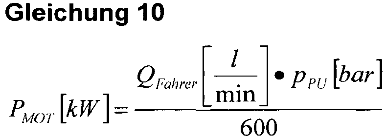
Die Komponente pPU stellt den Pumpendruck der Pumpe 3 dar. Eine Motorleistung PMot lässt sich auch durch folgende Formal berechnen: 
Wobei hier MMot für das Motordrehmoment steht. Setzt man Gleichungen 10 und 11 gleich 

Aus beiden Gleichung 9 und 12 ist ersichtlich, dass der Volumenstrom QFahrer immer von der Drehzahl ηMOT des Antriebsmotors 1 abhängig ist. Aus den beiden errechneten Motordrehzahlen (ηMOT, SPEED, ηMOT, POWER) wird die jeweils größere an das Motorsteuergerät gesendet. Das für die Motordrehzahl nach Gleichung 12 benötigte Motormoment MMOT kann entweder das aktuell vom Motorsteuergerät ausgegebene Motormoment oder ein aus einem Motorkennfeld ermitteltes Motormoment sein.From both
Auch bei diesem Regelalgorithmus kann zwischen den beiden bekannten Fällen unterschieden werden. Aus Gleichungen 9 und 12 ist ersichtlich, dass sich die Motordrehzahlen ηMOT, SPEED, ηMOT, POWER proportional zum Volumenström erhöhen. Die Kransteuerung ermittelt diese Motordrehzahlen kontinuierlich aus einem vom Fahrer gewünschten Volumenstrom QFahrer. Die größere der beiden Motordrehzahlen wird im Block 40 bestimmt und als Solldrehzahl ηMOT, MAX an den Antriebsmotor 1 gesendet. Nachdem sich die Solldrehzahl ηMOT,MAX eingestellt hat, fördert die Kranpumpe so viel Volumenstrom, wie es QFahrer entspricht.Even with this control algorithm, a distinction can be made between the two known cases. It can be seen from
Fall 1 wenig belasteter Hydraulikmotor 7:
Gegeben sind die folgenden Größen:
Given are the following sizes:
Der Kransteuerung 10 ermittelt aus dem vom Fahrer gewünschten Volumenstrom QFahrer die Motordrehzahlen ηMOT, SPEED und ηMOT, POWER. Im Falle des unbelasteten Hydraulikmotors 7 ist der gemessene Pumpendruck pPU sehr niedrig. Die ermittelte Motordrehzahl ηMOT, POWER wird im Vergleich zur Motordrehzahl ηMOT, SPEED sehr viel geringer sein. Das bedeutet, dass die Motordrehzahl ηMOT, SPEED als Solldrehzahl an den Kranmotor gesendet wird.The
Fall 2 stark belasteter Hydraulikmotor (7):
Gegeben:
Gegeben sind die folgenden Größen:
given:
Given are the following sizes:
Der Kransteuerung 10 ermittelt aus dem vom Fahrer gewünschten Volumenstrom QFahrer die Motordrehzahlen ηMOT, SPEED und ηMOT, POWER. Im Falle des belasteten Hydraulikmotors 7 ist der gemessene Pumpendruck pPU sehr hoch. Die ermittelte Motordrehzahl ηMOT, POWER wird im Vergleich zur Motordrehzahl ηMOT, SPEED sehr viel höher sein. Das bedeutet, dass die Motordrehzahl ηMOT, POWER als Solldrehzahl an den Kranmotor gesendet wird.The
Gemäß
Das Ausgangssignal des Hochlaufgebers 50 wird dann dem PT1-Glied 60 zugeführt. Als PT1-Glied bezeichnet man ein LZI-Übertragungsglied in der Regelungstechnik, welches ein proportionales Übertragungsverhalten mit Verzögerung 1. Ordnung aufweist.The output signal of the ramp-
Das PT1-Gliederhält als Eingangsgröße das Ausgangssignal ηMOT,MAX,PT1 des Hochlaufgebers 50 und erzeugt gemäß der in
Claims (14)
- Method for the speed synchronization of a hydraulic crane drive with at least one hydraulic consumer (7, 11), which is fed, via at least one hydraulic displacement pump (3), with an adjustable volumetric flow (QPU), wherein the at least one displacement pump (3) is driven by the drive unit (1) of the crane,
characterized in that
the speed (nMOT) of the drive unit (1) and the pivot angle of the at least one displacement pump (3) are controlled and/or adjusted as a function of the requested volumetric flow (QFAHRER) for at least one consumer (7, 11), and on the basis of a further parameter, by the crane control (10),
that the target speed (nSOLL) is calculated from the requested volumetric flow (QFAHRER),
that the speed synchronization can be overridden by a user input, in particular a gas pedal actuation (9), and
the speed (nMOT) of the drive unit (1) is increased until the volumetric flow (QPU1) determined from the instantaneous speed (nMOT) corresponds to the required volumetric flow (QFAHRER) or converges towards the same. - Method according to claim 1, characterized in that, additionally, at least one proportionally controllable directional seated valve (5) is activated.
- Method according to one of the preceding claims, characterized in that a control of the pivot angle occurs first, and a control of the speed (nMOT) occurs as necessary.
- Method according to one of the preceding claims, characterized in that the required volumetric flow (QFAHRER) is adjusted via at least one operating lever (6).
- Method according to claim 6, characterized in that the current lever position is signaled to the crane control selectively via a bus connection and/or radio frequency connection.
- Method according to one of the preceding claims, characterized in that the target speed (nSOLL) of the drive unit (1) is determined based on at last one characteristic map, in particular of the drive unit (1).
- Method according to one of the preceding claims, characterized in that the at least one further parameter is a value, which characterizes the height level above sea level of the crane, and/or a charging operation of an energy accumulator, and/or the efficiency/ies of all or at least a part of the consumers (7, 11), and/or at least one environmental condition, in particular the ambient temperature of the crane, and/or a direct specification, in particular target speed specification (nSOLL) of the crane.
- Method according to on of the preceding claims, characterized in that the volumetric flow (QRU1), determined from the instantaneous motor output (PMOT), and/or of the instantaneous pump pressure (pPU) can, via controlling of the speed (nMOT), be adjusted to the required volumetric flow (QFAHRER).
- Method according to one of the preceding claims, characterized in that the crane control (10) adapts, individually and load-dependently, to the acceleration- and/or deceleration ramps of the speed (nMOT) of the drive unit (1).
- Method according to one of the preceding claims, characterized in that the altering of the required volumetric flow (QFAHRER) is delayed and/or accelerated by means of a ramp function generator (30).
- Method according to one of the preceding claims, characterized in that the crane control (10), in multiple hydraulic consumers (7, 11), combines the individual required volumetric flows into a total demand (QFAHRER), and divides the maximum delivery amount, proportionally to the respective requirement, among the consumers (7, 11), in the event that the total demand (QFAHRER) exceeds the maximum delivery amount.
- Method according to one of the preceding claims, characterized in that the mechanical drive train is uncoupled in the event that the crane control (10) determines an idle operating mode.
- Hydraulic crane drive, with a crane control (10), for performing the method according to one of the preceding claims.
- Crane, in particular a mobile crane, with a crane drive according to claim 13.
Applications Claiming Priority (1)
| Application Number | Priority Date | Filing Date | Title |
|---|---|---|---|
| DE102012025253.6A DE102012025253A1 (en) | 2012-12-21 | 2012-12-21 | Method for speed tracking of a crane drive and crane drive |
Publications (3)
| Publication Number | Publication Date |
|---|---|
| EP2746212A2 EP2746212A2 (en) | 2014-06-25 |
| EP2746212A3 EP2746212A3 (en) | 2014-07-09 |
| EP2746212B1 true EP2746212B1 (en) | 2018-10-10 |
Family
ID=49766842
Family Applications (1)
| Application Number | Title | Priority Date | Filing Date |
|---|---|---|---|
| EP13006069.2A Active EP2746212B1 (en) | 2012-12-21 | 2013-12-19 | Method for tracking the rotational speed of a crane drive and crane drive |
Country Status (4)
| Country | Link |
|---|---|
| US (1) | US9399565B2 (en) |
| EP (1) | EP2746212B1 (en) |
| JP (1) | JP6563171B2 (en) |
| DE (1) | DE102012025253A1 (en) |
Families Citing this family (5)
| Publication number | Priority date | Publication date | Assignee | Title |
|---|---|---|---|---|
| US9599107B2 (en) * | 2013-02-22 | 2017-03-21 | Cnh Industrial America Llc | System and method for controlling a hydrostatic drive unit of a work vehicle using a combination of closed-loop and open-loop control |
| JP6156452B2 (en) * | 2015-07-23 | 2017-07-05 | コベルコ建機株式会社 | Mobile crane |
| EP3236328B8 (en) * | 2016-04-21 | 2019-03-06 | Kaeser Kompressoren SE | Method for analysing the compressed air supply security of a compressed air installation |
| CN106315411A (en) * | 2016-10-27 | 2017-01-11 | 安徽柳工起重机有限公司 | Speed control system of automobile crane |
| EP3725727A1 (en) * | 2019-04-18 | 2020-10-21 | Deere & Company | Control system for a crane of a working machine, method and working machine |
Family Cites Families (20)
| Publication number | Priority date | Publication date | Assignee | Title |
|---|---|---|---|---|
| DE3443354A1 (en) * | 1984-11-28 | 1986-05-28 | Robert Bosch Gmbh, 7000 Stuttgart | HYDRAULIC SYSTEM |
| JP2567222B2 (en) * | 1986-04-01 | 1996-12-25 | 株式会社小松製作所 | Engine control method and apparatus for wheeled construction machine |
| JP2511925B2 (en) * | 1987-01-30 | 1996-07-03 | 株式会社小松製作所 | Construction machine engine speed control device |
| US5477679A (en) | 1990-10-16 | 1995-12-26 | Hitachi Construction Machinery Co., Ltd. | Apparatus for controlling revolution speed of prime mover for hydraulically propelled work vehicle |
| DE4102621A1 (en) * | 1991-01-30 | 1992-08-06 | Orenstein & Koppel Ag | HYDROSTATIC DRIVE FOR WORKING MACHINES |
| JP2579571B2 (en) * | 1992-01-07 | 1997-02-05 | 川崎重工業株式会社 | Hydraulic circuit with flow control of hydraulic machine |
| DE4316361C2 (en) * | 1993-05-15 | 1999-04-01 | Radosav Nikolic | Hydraulic industrial truck |
| JP3525491B2 (en) * | 1994-06-01 | 2004-05-10 | コベルコ建機株式会社 | Hydraulic actuator circuit |
| JP4074676B2 (en) * | 1996-09-19 | 2008-04-09 | 株式会社神戸製鋼所 | Control method of hydraulic machine |
| US5967756A (en) * | 1997-07-01 | 1999-10-19 | Caterpillar Inc. | Power management control system for a hydraulic work machine |
| JP3868112B2 (en) * | 1998-05-22 | 2007-01-17 | 株式会社小松製作所 | Control device for hydraulic drive machine |
| JP3660501B2 (en) * | 1998-05-28 | 2005-06-15 | 日立建機株式会社 | Engine speed control device for construction machinery |
| DE19957791A1 (en) * | 1999-12-01 | 2001-06-07 | Guenter W Klemm | Hydraulic drill drive |
| JP4364408B2 (en) * | 2000-06-23 | 2009-11-18 | 株式会社タダノ | Working machine restriction device |
| JP2002179387A (en) * | 2000-10-03 | 2002-06-26 | Komatsu Ltd | Device and its method for controlling speed of work vehicle |
| JP2003120605A (en) * | 2001-10-12 | 2003-04-23 | Hitachi Constr Mach Co Ltd | Hydraulic driving device for hydraulic machine |
| US7588118B2 (en) * | 2003-05-07 | 2009-09-15 | Komatsu Ltd. | Work machine with engine control device |
| WO2008056526A1 (en) * | 2006-11-09 | 2008-05-15 | Furukawa Unic Corporation | Pressurized-oil supply amount control device for vehicle-mounted crane |
| CN101993006B (en) * | 2010-10-12 | 2012-07-04 | 三一汽车起重机械有限公司 | Automobile crane and energy-saving control method and energy-saving control system thereof |
| US9181070B2 (en) | 2011-05-13 | 2015-11-10 | Kabushiki Kaisha Kobe Seiko Sho | Hydraulic driving apparatus for working machine |
-
2012
- 2012-12-21 DE DE102012025253.6A patent/DE102012025253A1/en not_active Withdrawn
-
2013
- 2013-12-19 EP EP13006069.2A patent/EP2746212B1/en active Active
- 2013-12-20 US US14/137,140 patent/US9399565B2/en active Active
- 2013-12-24 JP JP2013266156A patent/JP6563171B2/en active Active
Non-Patent Citations (1)
| Title |
|---|
| None * |
Also Published As
| Publication number | Publication date |
|---|---|
| JP6563171B2 (en) | 2019-08-21 |
| EP2746212A2 (en) | 2014-06-25 |
| EP2746212A3 (en) | 2014-07-09 |
| US9399565B2 (en) | 2016-07-26 |
| US20140283507A1 (en) | 2014-09-25 |
| JP2014122704A (en) | 2014-07-03 |
| DE102012025253A1 (en) | 2014-07-10 |
Similar Documents
| Publication | Publication Date | Title |
|---|---|---|
| EP0698518B1 (en) | Method and controlling means for controlling the propulsion unit of a working vehicle | |
| DE112005001920B4 (en) | Load control device for the engine of a work vehicle | |
| EP2050961B1 (en) | Hydraulic drive system | |
| EP2746212B1 (en) | Method for tracking the rotational speed of a crane drive and crane drive | |
| DE102015209356B3 (en) | LOAD-RELATED CONTROL OF HYDRAULIC MOTORS | |
| EP1595077B1 (en) | Method for controlling a hydraulic system of a mobile working machine | |
| EP3587794B1 (en) | Hydrostatic drive and method for actuating a hydrostatic drive | |
| DE112007002112T5 (en) | Construction Vehicle | |
| EP3313770B1 (en) | Crane and method for controlling same | |
| DE102013021607A1 (en) | Self-propelled work machine and method for braking such a work machine | |
| EP2767739B1 (en) | Power-split transmission for a vehicle propulsion system, method for controlling the transmission | |
| DE102014224337A1 (en) | Method for controlling a hydrostatic drive | |
| DE112011102866T5 (en) | Control unit for forklift engine | |
| DE102010015409A1 (en) | Method for limiting a pressure in a hydrostatic transmission | |
| EP2789488A2 (en) | Drive system | |
| EP2789882B1 (en) | Power-splitting transmission for a vehicle propulsion system and method for controlling the transmission | |
| DE102008025683B4 (en) | Procedure for controlling a travel drive | |
| DE102016200336A1 (en) | A method of operating a vehicle driveline of a work machine having an engine, a transmission, and an output | |
| DE102019206770A1 (en) | Hydrostatic transmission, mobile working machine with the transmission and method for controlling the transmission | |
| EP3832165B1 (en) | Drive for a vehicle with a transmission and control architecture for controlling the transmission | |
| EP1826054A2 (en) | Method and device for controlling a hydraulic drive system | |
| DE102013213896A1 (en) | Method and system for regulating a pressure | |
| EP2191996B1 (en) | Mobile work machine, in particular industrial truck and method for operating the mobile work machine | |
| EP3680138B1 (en) | Control for a mobile work machine, control circuit, method and work machine | |
| DE102009013341A1 (en) | Method for controlling speed of internal combustion engine i.e. diesel engine in mobile work machine, involves controlling speed of internal combustion engine based on rate of utilization of internal combustion engine |
Legal Events
| Date | Code | Title | Description |
|---|---|---|---|
| PUAL | Search report despatched |
Free format text: ORIGINAL CODE: 0009013 |
|
| PUAI | Public reference made under article 153(3) epc to a published international application that has entered the european phase |
Free format text: ORIGINAL CODE: 0009012 |
|
| 17P | Request for examination filed |
Effective date: 20131219 |
|
| AK | Designated contracting states |
Kind code of ref document: A2 Designated state(s): AL AT BE BG CH CY CZ DE DK EE ES FI FR GB GR HR HU IE IS IT LI LT LU LV MC MK MT NL NO PL PT RO RS SE SI SK SM TR |
|
| AX | Request for extension of the european patent |
Extension state: BA ME |
|
| RIN1 | Information on inventor provided before grant (corrected) |
Inventor name: KISSELBACH, ALEXANDER |
|
| AK | Designated contracting states |
Kind code of ref document: A3 Designated state(s): AL AT BE BG CH CY CZ DE DK EE ES FI FR GB GR HR HU IE IS IT LI LT LU LV MC MK MT NL NO PL PT RO RS SE SI SK SM TR |
|
| AX | Request for extension of the european patent |
Extension state: BA ME |
|
| RIC1 | Information provided on ipc code assigned before grant |
Ipc: B66C 13/20 20060101AFI20140530BHEP |
|
| R17P | Request for examination filed (corrected) |
Effective date: 20150109 |
|
| 17Q | First examination report despatched |
Effective date: 20161024 |
|
| GRAP | Despatch of communication of intention to grant a patent |
Free format text: ORIGINAL CODE: EPIDOSNIGR1 |
|
| INTG | Intention to grant announced |
Effective date: 20180430 |
|
| GRAS | Grant fee paid |
Free format text: ORIGINAL CODE: EPIDOSNIGR3 |
|
| GRAA | (expected) grant |
Free format text: ORIGINAL CODE: 0009210 |
|
| AK | Designated contracting states |
Kind code of ref document: B1 Designated state(s): AL AT BE BG CH CY CZ DE DK EE ES FI FR GB GR HR HU IE IS IT LI LT LU LV MC MK MT NL NO PL PT RO RS SE SI SK SM TR |
|
| REG | Reference to a national code |
Ref country code: GB Ref legal event code: FG4D Free format text: NOT ENGLISH |
|
| REG | Reference to a national code |
Ref country code: CH Ref legal event code: EP Ref country code: AT Ref legal event code: REF Ref document number: 1050989 Country of ref document: AT Kind code of ref document: T Effective date: 20181015 |
|
| REG | Reference to a national code |
Ref country code: IE Ref legal event code: FG4D Free format text: LANGUAGE OF EP DOCUMENT: GERMAN |
|
| REG | Reference to a national code |
Ref country code: DE Ref legal event code: R096 Ref document number: 502013011259 Country of ref document: DE |
|
| REG | Reference to a national code |
Ref country code: NL Ref legal event code: MP Effective date: 20181010 |
|
| REG | Reference to a national code |
Ref country code: LT Ref legal event code: MG4D |
|
| PG25 | Lapsed in a contracting state [announced via postgrant information from national office to epo] |
Ref country code: NL Free format text: LAPSE BECAUSE OF FAILURE TO SUBMIT A TRANSLATION OF THE DESCRIPTION OR TO PAY THE FEE WITHIN THE PRESCRIBED TIME-LIMIT Effective date: 20181010 |
|
| PG25 | Lapsed in a contracting state [announced via postgrant information from national office to epo] |
Ref country code: ES Free format text: LAPSE BECAUSE OF FAILURE TO SUBMIT A TRANSLATION OF THE DESCRIPTION OR TO PAY THE FEE WITHIN THE PRESCRIBED TIME-LIMIT Effective date: 20181010 Ref country code: LV Free format text: LAPSE BECAUSE OF FAILURE TO SUBMIT A TRANSLATION OF THE DESCRIPTION OR TO PAY THE FEE WITHIN THE PRESCRIBED TIME-LIMIT Effective date: 20181010 Ref country code: FI Free format text: LAPSE BECAUSE OF FAILURE TO SUBMIT A TRANSLATION OF THE DESCRIPTION OR TO PAY THE FEE WITHIN THE PRESCRIBED TIME-LIMIT Effective date: 20181010 Ref country code: LT Free format text: LAPSE BECAUSE OF FAILURE TO SUBMIT A TRANSLATION OF THE DESCRIPTION OR TO PAY THE FEE WITHIN THE PRESCRIBED TIME-LIMIT Effective date: 20181010 Ref country code: HR Free format text: LAPSE BECAUSE OF FAILURE TO SUBMIT A TRANSLATION OF THE DESCRIPTION OR TO PAY THE FEE WITHIN THE PRESCRIBED TIME-LIMIT Effective date: 20181010 Ref country code: PL Free format text: LAPSE BECAUSE OF FAILURE TO SUBMIT A TRANSLATION OF THE DESCRIPTION OR TO PAY THE FEE WITHIN THE PRESCRIBED TIME-LIMIT Effective date: 20181010 Ref country code: BG Free format text: LAPSE BECAUSE OF FAILURE TO SUBMIT A TRANSLATION OF THE DESCRIPTION OR TO PAY THE FEE WITHIN THE PRESCRIBED TIME-LIMIT Effective date: 20190110 Ref country code: NO Free format text: LAPSE BECAUSE OF FAILURE TO SUBMIT A TRANSLATION OF THE DESCRIPTION OR TO PAY THE FEE WITHIN THE PRESCRIBED TIME-LIMIT Effective date: 20190110 Ref country code: IS Free format text: LAPSE BECAUSE OF FAILURE TO SUBMIT A TRANSLATION OF THE DESCRIPTION OR TO PAY THE FEE WITHIN THE PRESCRIBED TIME-LIMIT Effective date: 20190210 |
|
| PG25 | Lapsed in a contracting state [announced via postgrant information from national office to epo] |
Ref country code: RS Free format text: LAPSE BECAUSE OF FAILURE TO SUBMIT A TRANSLATION OF THE DESCRIPTION OR TO PAY THE FEE WITHIN THE PRESCRIBED TIME-LIMIT Effective date: 20181010 Ref country code: PT Free format text: LAPSE BECAUSE OF FAILURE TO SUBMIT A TRANSLATION OF THE DESCRIPTION OR TO PAY THE FEE WITHIN THE PRESCRIBED TIME-LIMIT Effective date: 20190210 Ref country code: GR Free format text: LAPSE BECAUSE OF FAILURE TO SUBMIT A TRANSLATION OF THE DESCRIPTION OR TO PAY THE FEE WITHIN THE PRESCRIBED TIME-LIMIT Effective date: 20190111 Ref country code: AL Free format text: LAPSE BECAUSE OF FAILURE TO SUBMIT A TRANSLATION OF THE DESCRIPTION OR TO PAY THE FEE WITHIN THE PRESCRIBED TIME-LIMIT Effective date: 20181010 Ref country code: SE Free format text: LAPSE BECAUSE OF FAILURE TO SUBMIT A TRANSLATION OF THE DESCRIPTION OR TO PAY THE FEE WITHIN THE PRESCRIBED TIME-LIMIT Effective date: 20181010 |
|
| REG | Reference to a national code |
Ref country code: DE Ref legal event code: R097 Ref document number: 502013011259 Country of ref document: DE |
|
| PG25 | Lapsed in a contracting state [announced via postgrant information from national office to epo] |
Ref country code: CZ Free format text: LAPSE BECAUSE OF FAILURE TO SUBMIT A TRANSLATION OF THE DESCRIPTION OR TO PAY THE FEE WITHIN THE PRESCRIBED TIME-LIMIT Effective date: 20181010 Ref country code: DK Free format text: LAPSE BECAUSE OF FAILURE TO SUBMIT A TRANSLATION OF THE DESCRIPTION OR TO PAY THE FEE WITHIN THE PRESCRIBED TIME-LIMIT Effective date: 20181010 |
|
| REG | Reference to a national code |
Ref country code: CH Ref legal event code: PL |
|
| PLBE | No opposition filed within time limit |
Free format text: ORIGINAL CODE: 0009261 |
|
| STAA | Information on the status of an ep patent application or granted ep patent |
Free format text: STATUS: NO OPPOSITION FILED WITHIN TIME LIMIT |
|
| PG25 | Lapsed in a contracting state [announced via postgrant information from national office to epo] |
Ref country code: LU Free format text: LAPSE BECAUSE OF NON-PAYMENT OF DUE FEES Effective date: 20181219 Ref country code: EE Free format text: LAPSE BECAUSE OF FAILURE TO SUBMIT A TRANSLATION OF THE DESCRIPTION OR TO PAY THE FEE WITHIN THE PRESCRIBED TIME-LIMIT Effective date: 20181010 Ref country code: SM Free format text: LAPSE BECAUSE OF FAILURE TO SUBMIT A TRANSLATION OF THE DESCRIPTION OR TO PAY THE FEE WITHIN THE PRESCRIBED TIME-LIMIT Effective date: 20181010 Ref country code: SK Free format text: LAPSE BECAUSE OF FAILURE TO SUBMIT A TRANSLATION OF THE DESCRIPTION OR TO PAY THE FEE WITHIN THE PRESCRIBED TIME-LIMIT Effective date: 20181010 Ref country code: MC Free format text: LAPSE BECAUSE OF FAILURE TO SUBMIT A TRANSLATION OF THE DESCRIPTION OR TO PAY THE FEE WITHIN THE PRESCRIBED TIME-LIMIT Effective date: 20181010 Ref country code: RO Free format text: LAPSE BECAUSE OF FAILURE TO SUBMIT A TRANSLATION OF THE DESCRIPTION OR TO PAY THE FEE WITHIN THE PRESCRIBED TIME-LIMIT Effective date: 20181010 |
|
| 26N | No opposition filed |
Effective date: 20190711 |
|
| REG | Reference to a national code |
Ref country code: IE Ref legal event code: MM4A |
|
| GBPC | Gb: european patent ceased through non-payment of renewal fee |
Effective date: 20190110 |
|
| REG | Reference to a national code |
Ref country code: BE Ref legal event code: MM Effective date: 20181231 |
|
| PG25 | Lapsed in a contracting state [announced via postgrant information from national office to epo] |
Ref country code: IE Free format text: LAPSE BECAUSE OF NON-PAYMENT OF DUE FEES Effective date: 20181219 Ref country code: SI Free format text: LAPSE BECAUSE OF FAILURE TO SUBMIT A TRANSLATION OF THE DESCRIPTION OR TO PAY THE FEE WITHIN THE PRESCRIBED TIME-LIMIT Effective date: 20181010 |
|
| PG25 | Lapsed in a contracting state [announced via postgrant information from national office to epo] |
Ref country code: BE Free format text: LAPSE BECAUSE OF NON-PAYMENT OF DUE FEES Effective date: 20181231 |
|
| PG25 | Lapsed in a contracting state [announced via postgrant information from national office to epo] |
Ref country code: GB Free format text: LAPSE BECAUSE OF NON-PAYMENT OF DUE FEES Effective date: 20190110 Ref country code: CH Free format text: LAPSE BECAUSE OF NON-PAYMENT OF DUE FEES Effective date: 20181231 Ref country code: LI Free format text: LAPSE BECAUSE OF NON-PAYMENT OF DUE FEES Effective date: 20181231 |
|
| PG25 | Lapsed in a contracting state [announced via postgrant information from national office to epo] |
Ref country code: MT Free format text: LAPSE BECAUSE OF FAILURE TO SUBMIT A TRANSLATION OF THE DESCRIPTION OR TO PAY THE FEE WITHIN THE PRESCRIBED TIME-LIMIT Effective date: 20181010 |
|
| REG | Reference to a national code |
Ref country code: AT Ref legal event code: MM01 Ref document number: 1050989 Country of ref document: AT Kind code of ref document: T Effective date: 20181219 |
|
| PG25 | Lapsed in a contracting state [announced via postgrant information from national office to epo] |
Ref country code: TR Free format text: LAPSE BECAUSE OF FAILURE TO SUBMIT A TRANSLATION OF THE DESCRIPTION OR TO PAY THE FEE WITHIN THE PRESCRIBED TIME-LIMIT Effective date: 20181010 |
|
| PG25 | Lapsed in a contracting state [announced via postgrant information from national office to epo] |
Ref country code: AT Free format text: LAPSE BECAUSE OF NON-PAYMENT OF DUE FEES Effective date: 20181219 |
|
| PG25 | Lapsed in a contracting state [announced via postgrant information from national office to epo] |
Ref country code: CY Free format text: LAPSE BECAUSE OF FAILURE TO SUBMIT A TRANSLATION OF THE DESCRIPTION OR TO PAY THE FEE WITHIN THE PRESCRIBED TIME-LIMIT Effective date: 20181010 Ref country code: HU Free format text: LAPSE BECAUSE OF FAILURE TO SUBMIT A TRANSLATION OF THE DESCRIPTION OR TO PAY THE FEE WITHIN THE PRESCRIBED TIME-LIMIT; INVALID AB INITIO Effective date: 20131219 Ref country code: MK Free format text: LAPSE BECAUSE OF NON-PAYMENT OF DUE FEES Effective date: 20181010 |
|
| PGFP | Annual fee paid to national office [announced via postgrant information from national office to epo] |
Ref country code: DE Payment date: 20220606 Year of fee payment: 10 |
|
| P01 | Opt-out of the competence of the unified patent court (upc) registered |
Effective date: 20230607 |
|
| PGFP | Annual fee paid to national office [announced via postgrant information from national office to epo] |
Ref country code: IT Payment date: 20231227 Year of fee payment: 11 Ref country code: FR Payment date: 20231220 Year of fee payment: 11 |