EP0698518B1 - Method and controlling means for controlling the propulsion unit of a working vehicle - Google Patents
Method and controlling means for controlling the propulsion unit of a working vehicle Download PDFInfo
- Publication number
- EP0698518B1 EP0698518B1 EP95112738A EP95112738A EP0698518B1 EP 0698518 B1 EP0698518 B1 EP 0698518B1 EP 95112738 A EP95112738 A EP 95112738A EP 95112738 A EP95112738 A EP 95112738A EP 0698518 B1 EP0698518 B1 EP 0698518B1
- Authority
- EP
- European Patent Office
- Prior art keywords
- engine
- speed
- rotation
- transmission
- initial
- Prior art date
- Legal status (The legal status is an assumption and is not a legal conclusion. Google has not performed a legal analysis and makes no representation as to the accuracy of the status listed.)
- Expired - Lifetime
Links
Images


Classifications
-
- B—PERFORMING OPERATIONS; TRANSPORTING
- B60—VEHICLES IN GENERAL
- B60W—CONJOINT CONTROL OF VEHICLE SUB-UNITS OF DIFFERENT TYPE OR DIFFERENT FUNCTION; CONTROL SYSTEMS SPECIALLY ADAPTED FOR HYBRID VEHICLES; ROAD VEHICLE DRIVE CONTROL SYSTEMS FOR PURPOSES NOT RELATED TO THE CONTROL OF A PARTICULAR SUB-UNIT
- B60W10/00—Conjoint control of vehicle sub-units of different type or different function
- B60W10/04—Conjoint control of vehicle sub-units of different type or different function including control of propulsion units
- B60W10/06—Conjoint control of vehicle sub-units of different type or different function including control of propulsion units including control of combustion engines
-
- B—PERFORMING OPERATIONS; TRANSPORTING
- B60—VEHICLES IN GENERAL
- B60W—CONJOINT CONTROL OF VEHICLE SUB-UNITS OF DIFFERENT TYPE OR DIFFERENT FUNCTION; CONTROL SYSTEMS SPECIALLY ADAPTED FOR HYBRID VEHICLES; ROAD VEHICLE DRIVE CONTROL SYSTEMS FOR PURPOSES NOT RELATED TO THE CONTROL OF A PARTICULAR SUB-UNIT
- B60W10/00—Conjoint control of vehicle sub-units of different type or different function
- B60W10/10—Conjoint control of vehicle sub-units of different type or different function including control of change-speed gearings
- B60W10/101—Infinitely variable gearings
-
- B—PERFORMING OPERATIONS; TRANSPORTING
- B60—VEHICLES IN GENERAL
- B60W—CONJOINT CONTROL OF VEHICLE SUB-UNITS OF DIFFERENT TYPE OR DIFFERENT FUNCTION; CONTROL SYSTEMS SPECIALLY ADAPTED FOR HYBRID VEHICLES; ROAD VEHICLE DRIVE CONTROL SYSTEMS FOR PURPOSES NOT RELATED TO THE CONTROL OF A PARTICULAR SUB-UNIT
- B60W30/00—Purposes of road vehicle drive control systems not related to the control of a particular sub-unit, e.g. of systems using conjoint control of vehicle sub-units, or advanced driver assistance systems for ensuring comfort, stability and safety or drive control systems for propelling or retarding the vehicle
- B60W30/18—Propelling the vehicle
- B60W30/188—Controlling power parameters of the driveline, e.g. determining the required power
- B60W30/1882—Controlling power parameters of the driveline, e.g. determining the required power characterised by the working point of the engine, e.g. by using engine output chart
-
- F—MECHANICAL ENGINEERING; LIGHTING; HEATING; WEAPONS; BLASTING
- F16—ENGINEERING ELEMENTS AND UNITS; GENERAL MEASURES FOR PRODUCING AND MAINTAINING EFFECTIVE FUNCTIONING OF MACHINES OR INSTALLATIONS; THERMAL INSULATION IN GENERAL
- F16H—GEARING
- F16H47/00—Combinations of mechanical gearing with fluid clutches or fluid gearing
- F16H47/02—Combinations of mechanical gearing with fluid clutches or fluid gearing the fluid gearing being of the volumetric type
- F16H47/04—Combinations of mechanical gearing with fluid clutches or fluid gearing the fluid gearing being of the volumetric type the mechanical gearing being of the type with members having orbital motion
-
- F—MECHANICAL ENGINEERING; LIGHTING; HEATING; WEAPONS; BLASTING
- F16—ENGINEERING ELEMENTS AND UNITS; GENERAL MEASURES FOR PRODUCING AND MAINTAINING EFFECTIVE FUNCTIONING OF MACHINES OR INSTALLATIONS; THERMAL INSULATION IN GENERAL
- F16H—GEARING
- F16H61/00—Control functions within control units of change-speed- or reversing-gearings for conveying rotary motion ; Control of exclusively fluid gearing, friction gearing, gearings with endless flexible members or other particular types of gearing
- F16H61/38—Control of exclusively fluid gearing
- F16H61/40—Control of exclusively fluid gearing hydrostatic
- F16H61/46—Automatic regulation in accordance with output requirements
- F16H61/462—Automatic regulation in accordance with output requirements for achieving a target speed ratio
-
- F—MECHANICAL ENGINEERING; LIGHTING; HEATING; WEAPONS; BLASTING
- F16—ENGINEERING ELEMENTS AND UNITS; GENERAL MEASURES FOR PRODUCING AND MAINTAINING EFFECTIVE FUNCTIONING OF MACHINES OR INSTALLATIONS; THERMAL INSULATION IN GENERAL
- F16H—GEARING
- F16H61/00—Control functions within control units of change-speed- or reversing-gearings for conveying rotary motion ; Control of exclusively fluid gearing, friction gearing, gearings with endless flexible members or other particular types of gearing
- F16H61/66—Control functions within control units of change-speed- or reversing-gearings for conveying rotary motion ; Control of exclusively fluid gearing, friction gearing, gearings with endless flexible members or other particular types of gearing specially adapted for continuously variable gearings
-
- B—PERFORMING OPERATIONS; TRANSPORTING
- B60—VEHICLES IN GENERAL
- B60W—CONJOINT CONTROL OF VEHICLE SUB-UNITS OF DIFFERENT TYPE OR DIFFERENT FUNCTION; CONTROL SYSTEMS SPECIALLY ADAPTED FOR HYBRID VEHICLES; ROAD VEHICLE DRIVE CONTROL SYSTEMS FOR PURPOSES NOT RELATED TO THE CONTROL OF A PARTICULAR SUB-UNIT
- B60W2510/00—Input parameters relating to a particular sub-units
- B60W2510/06—Combustion engines, Gas turbines
- B60W2510/0604—Throttle position
-
- B—PERFORMING OPERATIONS; TRANSPORTING
- B60—VEHICLES IN GENERAL
- B60W—CONJOINT CONTROL OF VEHICLE SUB-UNITS OF DIFFERENT TYPE OR DIFFERENT FUNCTION; CONTROL SYSTEMS SPECIALLY ADAPTED FOR HYBRID VEHICLES; ROAD VEHICLE DRIVE CONTROL SYSTEMS FOR PURPOSES NOT RELATED TO THE CONTROL OF A PARTICULAR SUB-UNIT
- B60W2510/00—Input parameters relating to a particular sub-units
- B60W2510/06—Combustion engines, Gas turbines
- B60W2510/0638—Engine speed
-
- B—PERFORMING OPERATIONS; TRANSPORTING
- B60—VEHICLES IN GENERAL
- B60W—CONJOINT CONTROL OF VEHICLE SUB-UNITS OF DIFFERENT TYPE OR DIFFERENT FUNCTION; CONTROL SYSTEMS SPECIALLY ADAPTED FOR HYBRID VEHICLES; ROAD VEHICLE DRIVE CONTROL SYSTEMS FOR PURPOSES NOT RELATED TO THE CONTROL OF A PARTICULAR SUB-UNIT
- B60W2710/00—Output or target parameters relating to a particular sub-units
- B60W2710/06—Combustion engines, Gas turbines
- B60W2710/0616—Position of fuel or air injector
-
- B—PERFORMING OPERATIONS; TRANSPORTING
- B60—VEHICLES IN GENERAL
- B60W—CONJOINT CONTROL OF VEHICLE SUB-UNITS OF DIFFERENT TYPE OR DIFFERENT FUNCTION; CONTROL SYSTEMS SPECIALLY ADAPTED FOR HYBRID VEHICLES; ROAD VEHICLE DRIVE CONTROL SYSTEMS FOR PURPOSES NOT RELATED TO THE CONTROL OF A PARTICULAR SUB-UNIT
- B60W2710/00—Output or target parameters relating to a particular sub-units
- B60W2710/10—Change speed gearings
- B60W2710/1005—Transmission ratio engaged
-
- F—MECHANICAL ENGINEERING; LIGHTING; HEATING; WEAPONS; BLASTING
- F16—ENGINEERING ELEMENTS AND UNITS; GENERAL MEASURES FOR PRODUCING AND MAINTAINING EFFECTIVE FUNCTIONING OF MACHINES OR INSTALLATIONS; THERMAL INSULATION IN GENERAL
- F16H—GEARING
- F16H59/00—Control inputs to control units of change-speed-, or reversing-gearings for conveying rotary motion
- F16H59/74—Inputs being a function of engine parameters
- F16H2059/743—Inputs being a function of engine parameters using engine performance or power for control of gearing
Landscapes
- Engineering & Computer Science (AREA)
- General Engineering & Computer Science (AREA)
- Mechanical Engineering (AREA)
- Chemical & Material Sciences (AREA)
- Combustion & Propulsion (AREA)
- Transportation (AREA)
- Automation & Control Theory (AREA)
- Control Of Transmission Device (AREA)
- Control Of Vehicle Engines Or Engines For Specific Uses (AREA)
- Hybrid Electric Vehicles (AREA)
- Electric Propulsion And Braking For Vehicles (AREA)
Abstract
Description
Die Erfindung betrifft ein Verfahren und eine Steuereinrichtung zur Steuerung des Antriebsstrangs eines Arbeitsfahrzeuges, welches eine Antriebsmaschine mit Einspritzmengenregelung und ein stufenlos verstellbares Getriebe (IVT) enthält, bei denen eine anfängliche Motorausgangsdrehzahl, eine anfängliche Raddrehzahl, die aktuelle Motordrehzahl und die aktuelle Raddrehzahl erfaßt und gespeichert werden.The invention relates to a method and a control device for controlling the drive train of a work vehicle, which contains a drive machine with injection quantity control and a continuously variable transmission (IVT), in which an initial engine output speed, an initial wheel speed, the current engine speed and the current wheel speed are recorded and stored will.
Der Antriebsstrang von Arbeitsfahrzeugen, wie landwirtschaftlichen oder gewerblichen Fahrzeugen enthält im wesentlichen einen Verbrennungsmotor und ein Getriebe. Der Motor hat die Aufgabe, die geforderte Leistung mit möglichst gutem Wirkungsgrad bereitzustellen, während das Getriebe als Drehmoment- und Drehzahlwandler das Kennfeld des Motors an das Bedarfsfeld des Fahrzeugs anpaßt. Bei der Weiterentwicklung des Antriebsstrangs treten neben den bisher vorrangigen Zielen einer Produktivitätssteigerung und einer Erhöhung des Komforts für den Fahrer zunehmend weitere Aspekte wie Emissionsverhalten und Kraftstoffverbrauch in den Vordergrund.The drive train of work vehicles, such as agricultural or commercial vehicles, essentially contains an internal combustion engine and a transmission. The engine has the task of providing the required performance with the best possible efficiency, while the transmission, as a torque and speed converter, adapts the engine's map to the vehicle's field of demand. In the further development of the drive train, in addition to the previous primary goals of increasing productivity and increasing comfort for the driver, other aspects such as emissions behavior and fuel consumption are increasingly coming to the fore.
Um diese Ziele zu erreichen, können stufenlos verstellbare Getriebe, wie sie beispielsweise durch die DE-A-35 33 193 und DE-A-41 15 623 beschrieben wurden, vorteilhaft eingesetzt werden. Es handelt sich hier um hydrostatisch-mechanische Leistungsverzweigungsgetriebe mit einem stufenlos verstellbaren hydrostatischen Teil, bestehend aus Verstellpumpe und Hydromotor, und einem mechanischen Zweig mit einigen Gängen, die ohne Zugkraftunterbrechung automatisch geschaltet werden können. Das Übertragungsverhältnis dieser Getriebe ist stufenlos über den gesamten Fahrbereich einstellbar.In order to achieve these goals, continuously variable transmissions, as described for example by DE-A-35 33 193 and DE-A-41 15 623, can be used advantageously. It is a hydrostatic-mechanical power split transmission with an infinitely adjustable hydrostatic part, consisting of a variable displacement pump and hydraulic motor, and a mechanical branch with a few gears that can be switched automatically without interrupting the tractive force. The transmission ratio of these transmissions is infinitely adjustable across the entire driving range.
Die EP-A-0 280 757 beschreibt eine Steuer- und Regeleinrichtung für ein derartiges stufenlos einstellbares Getriebe. Es werden laufend die Motoristdrehzahl und die Abtriebsistdrehzahl des Getriebes erfaßt und mit den Soll-Stellsignalen verglichen. Durch eine ständige Veränderung der Getriebeübersetzung und der Motordrehzahl reagiert die Regelung auf Änderungen der Stellsignale oder der Fahrbedingungen. Bei steigendem Fahrtwiderstand wird zunächst die Motordrehzahl gedrückt, was in einem Fahrregler eine Vergrößerung des Motorregelsignals bewirkt, um eine höhere Motorleistung bereitzustellen. Ferner erfolgt eine Anpassung der Getriebeübersetzung, um die gewünschte Fahrgeschwindigkeit einzuhalten bzw. zu erreichen. Die Regeleinrichtung soll so ausgelegt werden, daß ständig die verbrauchsoptimale Getriebeübersetzung sowie die verbrauchsoptimale Motordrehzahl eingestellt wird.EP-A-0 280 757 describes a control device for such a continuously variable transmission. The actual engine speed and the actual output speed of the gearbox are continuously recorded and compared with the setpoint control signals. By A constant change in the gear ratio and the engine speed, the control reacts to changes in the control signals or driving conditions. When the driving resistance increases, the engine speed is first pressed, which in an accelerator causes the engine control signal to increase in order to provide a higher engine output. Furthermore, the gear ratio is adjusted in order to maintain or achieve the desired driving speed. The control device should be designed so that the consumption-optimized gear ratio and the consumption-optimal engine speed are constantly set.
Ferner wurde im Jahr 1989 durch F. Jarchow auf einer Fachtagung in Dresden ein stufenlos wirkendes hydrostatisch-mechanisches Lastschaltgetriebe für Traktoren mit einer Steuerung vorgeschlagen, die eine Regelung auf einer Kurve minimalen Kraftstoffverbrauchs erlaubt. Anhand einer optimalen Kraftstoffverbrauchskurve läßt sich für jede Gaspedalstellung eine zugehörige Spannung ermitteln, die mit einer der Getriebeeingangsdrehzahl entsprechenden Spannung verglichen wird. Die Spannungsdifferenz wird zur Verstellung der Getriebeübersetzung herangezogen.Furthermore, in 1989 F. Jarchow proposed a continuously operating hydrostatic-mechanical powershift transmission for tractors with a control system that allows regulation on a curve with minimal fuel consumption at a specialist conference in Dresden. Using an optimal fuel consumption curve, an associated voltage can be determined for each accelerator pedal position, which voltage is compared with a voltage corresponding to the transmission input speed. The voltage difference is used to adjust the gear ratio.
Die der Erfindung zugrunde liegende Aufgabe besteht darin, ein erweitertes Verfahren und eine verbesserte Steuerungseinrichtung zur Steuerung des Antriebsstrangs von Arbeitsfahrzeugen der eingangs genannten Art anzugeben, durch die sich der Motor in Abhängigkeit vom Hauptfahrantrieb und gegebenenfalls von Sekundärantrieben für hydrostatische Pumpen, mechanische Zapfwellenantriebe und dergleichen hinsichtlich Produktivität, Kraftstoffeinsparung und Emissionsverhalten ohne zusätzlichen Aufwand für den Fahrer in einem günstigsten Arbeitsfeld betreiben läßt.The object on which the invention is based is to provide an expanded method and an improved control device for controlling the drive train of work vehicles of the type mentioned at the outset, by means of which the motor is dependent on the main drive and, if appropriate, on secondary drives for hydrostatic pumps, mechanical PTO drives and the like Productivity, fuel savings and emissions behavior can be operated in an inexpensive field without additional effort for the driver.
Die Aufgabe wird ausgehend von dem Oberbegriff der Patentansprüche 1 bzw. 9 durch deren kennzeichnende Merkmale gelöst. Weitere vorteilhafte Ausgestaltungen und Weiterbildungen der Erfindung gehen aus den Unteransprüchen hervor.The object is achieved on the basis of the preamble of claims 1 and 9 by their characterizing features. Further advantageous refinements and developments of the invention emerge from the subclaims.
Durch die Erfindung läßt sich das Ziel eines verringerten Kraftstoffverbrauchs bei gleichzeitig zurückgehender Emission sowie eine Komfortsteigerung für die Bedienungsperson erreichen. Die vorgeschlagene Strategie der Getriebeanpassung ermöglicht einen Betrieb des Motors in wirkungsgradgünstigen Kennfeldbereichen. Sie realisiert darüberhinaus eine verbesserte Produktivität kombiniert mit höherer Wirtschaftlichkeit.The aim of the invention is to reduce fuel consumption while at the same time reducing emissions achieve an increase in comfort for the operator. The proposed strategy of gear adaptation enables the engine to be operated in areas of the map that are efficient in terms of efficiency. It also realizes improved productivity combined with greater economy.
Um das Potential des Motors im Sinne der Aufgabenstellung voll auszunutzen, wird der Betriebspunkt des Motors durch Erhöhung (Erniedrigung) der Getriebeübersetzung bei unveränderten Fahrzeugparametern wie Geschwindigkeit und Last entlang der Drehmomenthyperbel konstanter Leistung verstellt, wobei die Belastung steigt und die Drehzahl des Motors abnimmt.In order to fully utilize the potential of the engine in the sense of the task, the operating point of the engine is adjusted by increasing (reducing) the transmission ratio with unchanged vehicle parameters such as speed and load along the torque hyperbola of constant power, whereby the load increases and the engine speed decreases.
Für die erfindungsgemäße Lösung wurde insbesondere die Erkenntnis genutzt, daß sich die Zugkrafthyperbeln des Fahrzeugs mit Hilfe der konstanten Achsuntersetzung auf die Hyperbeln konstanter Leistung des Antriebsstrangs normieren und abbilden lassen, so daß sich die Flächeninhalte und Beziehung der Rechtecke zu den Hyperbelpunkten leicht abschätzen und miteinander vergleichen lassen.For the solution according to the invention, the knowledge was used in particular that the traction force hyperbolas of the vehicle can be normalized and mapped with the help of the constant axle reduction to the hyperbolas of constant power of the drive train, so that the area and relationship of the rectangles to the hyperbolic points can be easily estimated and compared with one another to let.
Aus Kostengründen wird vorerst weiter von einer mechanischen Einspritzpumpe ausgegangen, die hinsichtlich der Einstellung der Einspritzmenge vornehmlich von der Getriebelektronik angesteuert wird. Das vorgeschlagene Verfahren läßt sich jedoch problemlos auf elektronisch geregelte Einspritzpumpen übertragen.For reasons of cost, a mechanical injection pump is initially assumed, which is primarily controlled by the transmission electronics with regard to the setting of the injection quantity. However, the proposed method can be easily transferred to electronically controlled injection pumps.
Da das Arbeitsgebiet des Motors nur mit motorspezifischen Parametern beschrieben wird, kann das Verfahren zur Steuerung eines Antriebsstrangs auf alle stufenlos verstellbaren Getriebe mit Leistungsverzweigung angewendet werden und deckt somit sowohl das rein mechanische und stufenlos verstellbare Leistungsverzweigungsgetriebe Torotrak der Firma Leyland, wie alle rein hydrostatischen oder hydrostatisch-mechanischen Getriebe mit Leistungsverzweigung ab.Since the field of operation of the engine is only described with engine-specific parameters, the method for controlling a drive train can be applied to all continuously variable transmissions with power split and thus covers both the purely mechanical and continuously variable power split transmission Torotrak from Leyland, as well as all purely hydrostatic or hydrostatic - mechanical gearbox with power split.
Die erfindungsgemäße Lösung ermöglicht eine einfache und flexible Steuerung von Getriebe und Motor, ohne daß Drehmomentaufnehmer erforderlich sind.The solution according to the invention enables simple and flexible control of the transmission and motor without the need for torque transducers.
Anhand der Zeichnung werden ein Ausführungsbeispiel der Erfindung gezeigt und die Erfindung sowie weitere Vorteile und vorteilhafte Weiterbildungen und Ausgestaltungen der Erfindung erläutert.An exemplary embodiment of the invention is shown on the basis of the drawing, and the invention and further advantages and advantageous developments and refinements of the invention are explained.
Es zeigt:
- Fig. 1
- das Blockdiagramm einer der erfindungsgemäßen Steuereinrichtungen,
- Fig. 2
- die Charakteristik eines beispielhaften Motors mit Definition der Kurven zur Regelung des Antriebsstrangs und
- Fig. 3 bis 5
- weitere Motorcharakteristiken zur Beschreibung der der Erfindung zugrunde liegenden Zusammenhänge.
- Fig. 1
- the block diagram of one of the control devices according to the invention,
- Fig. 2
- the characteristics of an exemplary engine with definition of the curves for regulating the drive train and
- 3 to 5
- Further motor characteristics to describe the relationships underlying the invention.
Das Blockdiagramm der Figur 1 zeigt einen drehzahlvariablen Motor 10, der durch einen als Mikroprozessor ausgebildeten Drehzahlsteller 12 ansteuerbar ist. Der Drehzahlsteller 12 ist vorzugsweise über einen CAN-Bus 14 oder über eine direkte Verbindung an einen Getriebe-Controller 18 angeschlossen, von dem er Steuersignale für die Einspritzpumpe des Motors 10 empfängt und an diese weitergibt. Die Einspritzpumpe ist damit nicht, wie bei konventionellen Fahrzeugen üblich, unmittelbar mit dem Gaspedal bzw. dem Handgashebel verbunden, sondern wird durch eine elektronische Regeleinheit eingestellt. Diese Regelung bestimmt unter Berücksichtigung des Fahrerwunsches (Hebel- und Pedaleinstellungen), der Betriebsbedingungen und des Kennfelds des Motors 10 die Einspritzmenge.The block diagram of FIG. 1 shows a variable-
Der Motor 10 treibt ohne Zwischenschaltung einer Kupplung ein stufenlos verstellbares Getriebe 16 an. Das Übersetzungsverhältnis des Getriebes 16 wird durch den Controller 18 als Übersetzungssteller eingestellt, der als Mikroprozessor ausgebildet und ebenfalls an den CAN-Bus 14 angeschlossen ist. Die elektronische Steuerung der Einspritzpumpe 12 und die Regeleinheit 18 des Getriebes 16 arbeiten zusammen und können eventuell zu einer Baueinheit kombiniert werden. An den CAN-Bus 14 ist ferner eine Bedieneroberfläche 20 angeschlossen, über die eine Bedienungsperson Vorgaben zur Beeinflussung des Antriebsstrangs einstellen kann.The
Der stufenlose Teil des Getriebes 16 besteht vorzugsweise aus einer Verstellpumpe mit Hydraulikmotor. Im mechanischen Zweig sind einige Gänge vorgesehen, die ohne Zugkraftunterbrechung automatisch geschaltet werden können. Das Getriebe ermöglicht über den stufenlosen Teil des Getriebes das Anfahren aus dem Stand ohne Anfahrkupplung. Für den Stillstand oder das Abbremsen des Fahrzeugs trennen nicht gezeigte Kupplungen den Antriebsstrang von den Treibrädern, um den Motor nicht abzuwürgen bzw. ein Arbeiten des Getriebes gegen die Bremsen zu vermeiden. Nach Beendigung des Bremsvorgangs schließen die Trennkupplungen bei Synchronlauf wieder automatisch. Anstelle eines derartigen Getriebes sind auch andere stufenlos einstellbare Getriebe verwendbar.The continuously variable part of the
Elektronische Drehzahlmeßwertgeber erfassen die Motorausgangsdrehzahl nm und die Getriebeausgangsdrehzahl, die der normierten Raddrehzahl nr der Antriebsräder entspricht. Die Drehzahlen nm und nr werden durch die elektronische Steuereinheit ständig gemessen und gespeichert. Aus ihnen werden je nach Sollwertvorgabe die Betriebspunkte für Motor und Getriebe bestimmt.Electronic speed sensors record the engine output speed n m and the transmission output speed, which corresponds to the normalized wheel speed n r of the drive wheels. The speeds n m and n r are continuously measured and stored by the electronic control unit. The operating points for the engine and transmission are determined from these, depending on the setpoint.
An den Ausgang des Motors 10 ist mittels Zahnrädern unmittelbar eine Hydraulikpumpe 22 zur Versorgung der Fahrzeugkomponenten und der angeschlossenen Geräte sowie eine Gerätezapfwelle 24 gekoppelt. Diese drehen daher proportional zur Motordrehzahl.A
Im Unterschied zu konventionellen Antriebskonzepten besitzt die Bedienungsperson des hier beschriebenen Fahrzeugs mit stufenlos verstellbarem Getriebe nun die Möglichkeit, über eine elektronische Regeleinheit (Antriebsmanagement) die Sollwertwünsche für Geschwindigkeit und Motordrehzahl etc. weiterzugeben. Eine direkte Beeinflussung des Motorbetriebspunktes oder der Getriebeübersetzung ist nicht mehr möglich.In contrast to conventional drive concepts, the operator of the vehicle described here with a continuously variable transmission now has the option of forwarding the setpoint requests for speed and engine speed etc. via an electronic control unit (drive management). It is no longer possible to directly influence the engine operating point or the gear ratio.
Die Bedienungsperson gibt den Sollwert vor, und die elektronische Regelung bestimmt die Art und Weise, wie diese Einstellung realisiert werden soll. Die Sollwerteingabe für die Fahrgeschwindigkeit kann über einen Geschwindigkeitswahlhebel, ein Gaspedal oder eine im Bremspedal integrierte Retarderstufe erfolgen, die hier nicht dargestellt sind, jedoch beispielsweise in WO-94/06651 beschrieben wurden. Die Fahrzeuggeschwindigkeit wird mit dem Wahlhebel vorgegeben. Mit dem Retarder oder dem Gaspedal ist ein Modulieren der Vorwahlgeschwindigkeit möglich, wobei über das Fußgaspedal die Geschwindigkeit erhöht bzw. bei vergrößerter Last beibehalten wird, während der Retarder das Fahrzeug ohne reibende Elemente verzögert. Ein zusätzlicher Handgashebel legt eine bestimmte Motordrehzahl fest, die entweder konstant zu halten ist (Zapfwellenbetrieb) oder nicht unterschritten werden darf.The operator specifies the setpoint and the electronic control determines how this setting is to be implemented. The setpoint input for the driving speed can be made via a speed selector lever, an accelerator pedal or a retarder stage integrated in the brake pedal, which are not shown here, but were described, for example, in WO-94/06651. The vehicle speed is specified with the selector lever. The retarder or the accelerator pedal can be used to modulate the pre-selection speed, with the foot accelerator pedal increasing the speed or maintaining it with an increased load, while the retarder decelerates the vehicle without any friction elements. An additional hand throttle lever specifies a certain engine speed, which must either be kept constant (PTO operation) or must not be undercut.
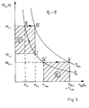
Das in Figur 2 dargestellte Motorkennfeld charakterisiert einen Motor, der für den Einsatz mit einem stufenlos verstellbaren Getriebe noch nicht optimal ausgelegt ist. Dieses erkennt man daran, daß der Punkt K des optimalen spezifischen Kraftstoffverbrauchs noch rechts vom Punkt Mmax des maximalen Motormomentes liegt.The engine map shown in FIG. 2 characterizes an engine that has not yet been optimally designed for use with a continuously variable transmission. This can be seen from the fact that the point K of the optimal specific fuel consumption is still to the right of the point M max of the maximum engine torque.
Es wurde das Motormoment Mm über der Ausgangsdrehzahl nm des Motors aufgetragen und die Vollastkurve MVoll eingetragen. Ferner sind die Drehmomenthyperbeln konstanter Leistung Pi , einschließlich der Nennleistung PN bei zugehöriger Nenndrehzahl nN ebenso wie die Linien der spezifischen Kraftstoffverbräuche b und Linien konstanter Einspritzpumpenstellung d eingezeichnet.The engine torque M m was plotted against the output speed n m of the engine and the full load curve M full was entered. The torque hyperbolas of constant power P i , including the nominal power P N at the associated nominal speed n N, as well as the lines of the specific fuel consumption b and lines of constant injection pump position d are shown.
Die Linien d werden im folgenden als P-Geraden bezeichnet. Sie ergeben sich aus an dem konkreten Motor bei konstanter Einspritzpumpenstellung ermittelten Meßpunkten, aus denen P-Kurven gebildet werden, die ihrerseits linearisiert und als P-Geraden in einem Speicher des Controllers abgelegt werden.The lines d are referred to below as P lines. They result from measuring points determined on the specific engine with a constant injection pump position, from which P-curves are formed, which in turn are linearized and stored as P-lines in a memory of the controller.
Ein Arbeitsfeld des Motors wird nach Figur 2 durch folgende Linien bzw. Kurven definiert:
- die Drehmomenthyperbel konstanter Leistung (P4 = 40%) des speziellen Anwendungsfalles, die sich aus Soll- und Istdrehzahl des Motors mit Hilfe der gespeicherten P-Geraden (proportionaler Drehmomentanstieg) ermitteln läßt,
- die Aufregellinie 1, die zur Abgrenzung des Rauchgebietes im Motorkennfeld vorzugsweise als Drehmomentgerade zwischen den Punkten der unteren Leerlaufdrehzahl und des maximalen Moments Mmax der Vollastkurve Mvoll festgelegt wurde,
- die
Vollastregellinie 2, die ebenfalls vorzugsweise als Gerade festgelegt ist und den Drehmomentverlauf im Bereich des günstigsten Kraftstoffverbrauchs definiert, und - die P-Kurve, die wie bereits beschrieben als momentanes Kennfeld definiert ist, nach der der Motor bei einer gegebenen Einspritzmenge auf eine geänderte Last reagiert.
- the torque hyperbola of constant power (P 4 = 40%) of the special application, which can be determined from the target and actual engine speed using the stored P-straight line (proportional torque increase),
- the up-stroke line 1, which was defined in full to delimit the smoking area in the engine map, preferably as a torque line between the points of the lower idling speed and the maximum torque M max of the full load curve M,
- the full-
load control line 2, which is also preferably defined as a straight line and defines the torque curve in the area of the most favorable fuel consumption, and - the P curve, which, as already described, is defined as the current characteristic map according to which the engine reacts to a changed load for a given injection quantity.
Stufenlos verstellbare Getriebe ohne Hauptkupplung haben eventuell den Nachteil, daß sie während des Anfahrvorgangs keine zusätzliche Energie aus dem Schwungrad ziehen können und somit ohne besondere Vorkehrungen als wenig reaktionsfreudig gelten können. Um diesem Verhalten entgegenzuwirken, verstellt das IVT-Getriebe beim Anfahrvorgang den Motor nicht entlang der Aufregellinie 1 oder gar links von dieser Kurve im Rauchgebiet, sondern gibt, eventuell sogar mit Hilfe des Handgases, mittlere Drehzahlen vor, um auf unbekannte Belastungsanforderungen vorbereitet zu sein.Infinitely variable transmissions without a main clutch may have the disadvantage that they cannot draw any additional energy from the flywheel during the start-up process and can therefore be considered unresponsive without special precautions. To counteract this behavior, the IVT gearbox does not adjust the engine along start-up line 1 or even to the left of this curve in the smoking area when starting off, but specifies medium speeds, possibly even with the help of hand throttle, in order to be prepared for unknown load requirements.
In Figur 2 wurde entsprechend einer beispielhaften P-Kurve (stark hervorgehoben) mit einer vorgegebenen Einspritzmenge die Leerlaufdrehzahl auf 2000 1/min eingestellt. Die mechanische Einspritzpumpe ist hierbei in der Lage, durch ihre interne Charakteristik den Anforderungen einer Laststeigerung eigenständig nachzukommen, wobei die Drehzahl des Motors von 2000 1/min auf einen Wert von 1920 gedrückt wurde. Da die P-Kurve durch eine P-Gerade digital nachgebildet und im IVT-Controller abgelegt wurde, konnte auf diese Weise der Lastanteil mit x = 40 % des Nennmoments ermittelt werden.In FIG. 2, the idle speed was set to 2000 rpm according to an exemplary P curve (strongly emphasized) with a predetermined injection quantity. The mechanical injection pump is able to independently meet the requirements of a load increase due to its internal characteristics, with the engine speed of 2000 Rpm was pressed to a value of 1920. Since the P curve was digitally simulated by a P straight line and stored in the IVT controller, the load share could be determined in this way with x = 40% of the nominal torque.
Die 40-%-Drehmomenthyperbel ist hiermit definiert und besitzt mit der Aufregellinie 1 einen definierten Schnittpunkt, so daß sich die Drehzahl des Motors inkremental in Richtung auf diesen Punkt einstellen läßt. Hierzu sind eventuell mehrere Rechenzyklen notwendig, wobei sich gleichzeitig auch das Lastniveau von Rechenzyklus zu Rechenzyklus verändern kann. Die mechanische Einspritzpumpe kann diesen Anforderungen problemlos folgen, so daß ausgehend von der momentanen P-Geraden, einem bekannten Wert für die Solldrehzahl und dem gemessenen Wert für die Istdrehzahl die Eingabeparameter für den nächsten Rechenzyklus bereitstehen, wie im vorigen Abschnitt erläutert wurde.The 40% torque hyperbola is defined here and has a defined intersection point with the control line 1, so that the speed of the motor can be set incrementally in the direction of this point. This may require several computing cycles, whereby the load level can also change from computing cycle to computing cycle at the same time. The mechanical injection pump can easily follow these requirements, so that starting from the current P straight line, a known value for the target speed and the measured value for the actual speed, the input parameters are available for the next calculation cycle, as explained in the previous section.
Sollte mittels des Handgases in der Zwischenzeit eine Mindestdrehzahl des Motors vorgegeben worden sein, so errechnet sich der Schnittpunkt der Hyperbel nicht mehr mit der Aufregellinie 1 sondern mit der Senkrechten S zu der Drehzahl, die mit dem Handgas eingestellt wurde. Der Vorgang läuft auch hier inkremental ab. Aus dem Vieleck der Aufregellinie 1, der Vollastgeraden 2; der P-Geraden und der Belastungshyperbel läßt sich als Fläche der Grad der möglichen Wirkungsgradverbesserung abschätzen (Wirkungsgradvieleck). Es ist deutlich, daß die Handgaseinstellung die Fläche des Wirkungsgradvielecks fast halbiert hat.If a minimum engine speed has been specified in the meantime by means of the hand throttle, the intersection of the hyperbola is no longer calculated with the up-stroke line 1 but with the perpendicular S to the speed that was set with the hand throttle. The process is also incremental here. From the polygon of the normal line 1, the
In der gleichen Weise wird bei Zapfwellenbetrieb mit dem Unterschied verfahren, daß die Handgaseinstellung weiter nach rechts in die Nähe der P-Kurve bzw. der Auslegungsdrehzahl der ausgewählten Zapfwelle verschoben wird, um Zapfwellendrehzahl konstant vorzugeben. Das Wirkungsgradvieleck schrumpft hierbei fast zu einem Punkt zusammen.The same procedure is used for PTO operation, with the difference that the hand throttle setting is shifted further to the right in the vicinity of the P curve or the design speed of the selected PTO shaft in order to specify a constant PTO shaft speed. The efficiency polygon shrinks almost to a point.
Das Wirkungsgradvieleck und das an dem Punkt A ansetzende Rechteck unter der Drehmomenthyperbel geben somit einen guten Überblick über den Status des Antriebstrangs hinsichtlich Leistung und Wirkungsgrad.The efficiency polygon and the rectangle starting at point A under the torque hyperbola thus provide a good overview of the status of the drive train with regard to performance and efficiency.
Bei einem für die Anwendung mit IVT bevorzugten Motor sollte der Punkt für den günstigsten Kraftstoffverbrauch äußerst links und oben im Motorkennfeld liegen (das heißt bei geringer Motordrehzahl), um durch eine große Reduzierung der Motordrehzahl auch eine große Verbesserung der mechanischen Wirkungsgrade von Motor und Getriebe zu erzielen und um bei optimaler thermischer Auslastung des Motors die Wirkungsgrade noch weiter zu verbessern.In the case of an engine preferred for use with IVT, the point for the cheapest fuel consumption should be on the extreme left and top of the engine map (i.e. at low engine speed) in order to achieve a great improvement in the mechanical efficiency of the engine and transmission due to a large reduction in engine speed achieve and to improve the efficiency even further with optimal thermal utilization of the motor.
Die Vollastgerade 2 verläuft bei konstantem Drehmoment vorzugsweise oberhalb des Punktes der Nennleistung PN und beginnend bei Drehzahlen kleiner nN, um eine Feinabstimmung des Kennfeldes des Motors mit dem des Getriebes zu ermöglichen. Die Abstimmung im Gebiet des günstigsten Kraftstoffverbrauchs erscheint unkritisch, solange die Muschelkurven flach liegende Elipsen darstellen. Die Vollastgerade 2 liegt zweckmäßigerweise 10 bis 15 % unterhalb der Vollastkurve MVoll, um bei schweren Zugarbeiten eine Drehmomentreserve für Spitzenbelastungen vorzuhalten und auf der anderen Seite, das Getriebe über eine längere Zeit nicht zu überfordern.The full-
Für relativ kleine Leistungen liegt der ausgeregelte Betriebspunkt des Motors auf der Aufregellinie 1. Bei einem weiteren Anstieg des Drehmoments verhält sich der Motor wie bereits beschrieben. Bei konstanter Einspritzmenge erhöht der Motor sein Drehmoment entlang der P-Kurve und der Betriebspunkt wandert über die Aufregellinie 1 hinaus nach links.For relatively small outputs, the regulated operating point of the motor lies on the up-stroke line 1. If the torque increases further, the motor behaves as already described. With a constant injection quantity, the engine increases its torque along the P curve and the operating point moves to the left beyond the excitation line 1.
Da sich die Logik für die Ermittlung der Motorsoll- und -istwerte nicht geändert hat, kann auch die zugehörige Hyperbel konstanter Leistung, wie beschrieben, ermittelt werden. Bei Betrachtung des Schnittpunktes der Hyperbel mit der Aufregellinie 1 stellt sich jedoch heraus, daß die Hyperbel oberhalb der Ausgangshyperbel liegt und nur durch Drehzahlerhöhung mit der Aufregellinie 1 zum Schnitt gebracht werden kann. Das Ergebnis ist ein Schnittpunkt der neuen Hyperbel mit der Aufregellinie 1 auf höherem Niveau. Um die gewünschte Fahrgeschwindigkeit einzuhalten, ist eine Anpassung des Übersetzungsverhältnisses des Getriebes erforderlich.Since the logic for determining the engine setpoints and actual values has not changed, the associated hyperbola of constant power can also be determined as described. When considering the point of intersection of the hyperbola with the up-stroke line 1, however, it turns out that the hyperbola lies above the starting hyperbola and can only be brought to the intersection with the up-stroke line 1 by increasing the speed. The result is an intersection of the new hyperbola with the normal line 1 at a higher level. In order to maintain the desired driving speed, it is necessary to adjust the gear ratio of the transmission.
Das beschriebene Verfahren trifft nach Figur 2 für Leistungsanforderungen bis zu etwa 63 % der Nennleistung zu. Die Hyperbeln größer 63 % schneiden die Aufregellinie 1 nicht mehr. Dafür haben sie jedoch einen Schnittpunkt mit der Vollastgeraden 2, so daß diese Einsatzfälle unterschieden werden müssen.According to FIG. 2, the described method applies to performance requirements up to approximately 63% of the nominal performance. The hyperbolas greater than 63% no longer intersect the line of incidence 1. However, they do have an intersection with the
Für Leistungen größer 63 % liegt der günstigste Motorbetriebspunkt auf der Vollastgeraden 2. Eine Last- oder auch Geschwindigkeitserhöhung (-erniedrigung) erfordert somit einen Leistungszuwachs (-abfall) des Motors, d.h. der Motorbetriebspunkt verschiebt sich auf der Vollastgeraden 2 weiter nach rechts (links). Dies geschieht wiederum in inkrementalen Schritten durch eine Steigerung (Absenkung) der Motordrehzahl. Unterhalb der Vollastgeraden 2 stehen jedoch alle Möglichkeiten der Wirkungsgradverbesserung durch eine Änderung des Übersetzungsverhältnisses und eine Verringerung der Geschwindigkeit bei gleichzeitiger Anhebung des Drehmoments in Richtung der Vollastgerade zur Verfügung. Die mit der Geschwindigkeitsverringerung verbundene Widerstandsreduzierung (-erhöhung) macht eventuell eine weitere Übersetzungsanpassung erforderlich.For outputs greater than 63%, the most favorable engine operating point is on the full load
Die Abregellinie 3 zur Drehzahlbegrenzung des Dieselmotors dient dem Schutz des Motors gegen Überdrehzahlen, Störungen der Elektronik oder gegen unsachgemäße Bedienung der Bedienungsperson (z. B. Vollgas bei Leerlauf). Sie ist bei der mechanischen Einspritzpumpe mechanisch, wird bei zukünftigen Einspritzpumpen jedoch in zunehmendem Maße elektronisch realisiert.The
Während eine Steigerung (Absenkung) der Fahrzeugleistung ausgehend von einem niedrigen Leistungsniveau (Aufregellinie 1) eine Verringerung (Erhöhung) des Übersetzungsverhältnisses bei gleichzeitiger Erhöhung (Verringerung) der Motordrehzahl erfordert, bedeutet eine Steigerung der Fahrleistung ausgehend von einem hohen Niveau (Vollastlinie 2) eine Erhöhung (Verringerung) des Übersetzungsverhältnisses bei gleichzeitiger Erhöhung (Verringerung) der Motordrehzahl.While an increase (decrease) in vehicle performance starting from a low performance level (control line 1) requires a reduction (increase) in the gear ratio while increasing (decrease) the engine speed, an increase in driving performance starting from a high level (full load line 2) means an increase (Reduction) of the gear ratio while increasing (reducing) the engine speed.
Das IVT erlaubt durch stufenlose Übersetzungsänderung das Befahren des ganzen Geschwindigkeitsbereichs bei gleicher Motorleistung. Wie aus Figur 3 hervorgeht, kann der Motorbetriebspunkt X durch Einstellung unterschiedlicher Getriebeübersetzungen i in einen durch Pfeile markierten Bereich Y der Zugkrafthyperbel verstellt werden, der zwischen einer minimalen Raddrehzahl nrmin und einer maximalen Raddrehzahl nrmax liegt. Aus den genannten Gründen könnte bei einem Fahrzeug mit IVT-Getriebe auf eine Konstantleistungscharakteristik des Motors verzichtet werden. Als Argument für die Beibehaltung der Konstantleistungscharakteristik können angeführt werden: größere Durchschlagskraft für schwere Zapfwellengeräte und eine mögliche Konsolidierung der Kennfelder von Motor und Getriebe.The IVT allows the entire speed range to be driven with the same engine power thanks to the continuously variable transmission ratio change. As can be seen from FIG. 3, the engine operating point X can be adjusted by setting different gear ratios i into an area Y of the traction force hyperbola marked by arrows which lies between a minimum wheel speed n rmin and a maximum wheel speed n rmax . For the reasons mentioned, a constant power characteristic of the engine could be dispensed with in a vehicle with an IVT transmission. The arguments for maintaining the constant power characteristics can be given: greater penetration for heavy PTO equipment and a possible consolidation of the engine and transmission characteristics.
Eine anschauliche Betrachtung der Leistung ermöglicht ihre Darstellung als Fläche im Drehmoment-Drehzahldiagramm. Wegen der Beziehung "![]()
![]()
Der Einfachheit halber wurde hierbei der Wirkungsgrad η zunächst außer Acht gelassen bzw. gleich 1 gesetzt. Einschränkungen dieser Art bestehen jedoch nicht, da sich der Wirkungsgrad in den nachfolgen Gleichungen herauskürzt.For the sake of simplicity, the efficiency η was initially disregarded or set equal to 1. However, there are no restrictions of this type because the efficiency is reduced in the following equations.
In Abhängigkeit von den auftretenden Stör- und Führungsgrößen werden durch geeignete Kontrollstrategien die notwendigen Einstellungen für einen neuen Betriebspunkt (IVT-Übersetzung, Motordrehzahl) ermittelt. Zu diesem Zweck werden die Motordrehzahl nm und die Abtriebsdrehzahl nr kontinuierlich gemessen und gespeichert. Um eine Laständerung zu erkennen, ist es notwendig, eine Raddrehzahl- oder Motordrehzahlabsenkung (-anhebung) zuzulassen und zu registrieren, bevor der Regelprozeß in Gang gesetzt werden kann.Depending on the disturbance and command variables that occur, suitable control strategies are used to determine the necessary settings for a new operating point (IVT ratio, engine speed). For this purpose, the engine speed n m and the output speed n r are continuously measured and stored. In order to detect a change in load, it is necessary to permit and register a wheel speed or engine speed reduction (increase) before the control process can be started.
Anhand der Figur 5 wird im folgenden die Kontrollstrategie bei Lasterhöhung (Motordrückung) erläutert. Der Motor wird auf der Vollastlinie, d. h. bei ![]()
![]()
Es werden die nachfolgenden Abkürzungen verwandt:
- nmo
- Motorausgangsdrehzahl (gemessen)
- nmn
- neue Motordrehzahl (gemessen)
- nms
- Motorsolldrehzahl (errechnet)
- nro
- Radausgangsdrehzahl (gemessen)
- nrn
- neue Raddrehzahl (gemessen)
- nrs
- Radsolldrehzahl (vorgegeben)
- Mmo
- konstantes Motorausgangsmoment
- Mro
- Ausgangsmoment des Rades
- Mrn
- neues Moment des Rades
- io
- IVT-Übersetzung im Ausgangspunkt (errechnet)
- in
- neue IVT-Übersetzung (errechnet)
- n mo
- Motor output speed (measured)
- n mn
- new engine speed (measured)
- n ms
- Target engine speed (calculated)
- n ro
- Wheel output speed (measured)
- n rn
- new wheel speed (measured)
- n rs
- Target wheel speed (specified)
- M mo
- constant engine output torque
- M ro
- Output torque of the wheel
- M rn
- new moment of the wheel
- ok
- IVT translation in the starting point (calculated)
- i n
- new IVT translation (calculated)
Laut Voraussetzung sind die Ein- und Ausgangsleistungen des Getriebes in folgender Weise miteinander verknüpft:![]()
![]()
Wegen der Flächengleichheit der Rechtecke nach Figur 5 gilt obige Beziehung auch für Differenzleistungen:![]()
![]()
Hieraus folgt für einen Übergang von (I) nach (III) für das Getriebe bzw. von (IV) nach (V) für den Motor:
Da diese Gleichungen noch ein Momentenverhältnis enthalten, aus technischen Gründen jedoch nur Drehzahlen gemessen werden sollen, ist eine Zerlegung des Vorgangs in zwei Phasen notwendig.Since these equations still contain a torque ratio, but for technical reasons only speeds should be measured, the process must be broken down into two phases.
In der ersten Phase wird auf die festgestellte Motordrückung (nmn < nmo) reagiert, indem die Übersetzung (![]()
![]()
In der zweiten Phase werden die Motordrehzahl (durch Erhöhung der Kraftstoffeinspritzmenge) und die Raddrehzahl bei konstanten Motor- und Radmomenten so lange gesteigert, bis die ursprüngliche Fahrgeschwindigkeit, die durch die Übersetzungsverstellung des ersten Schrittes abgesenkt wurde, wieder erreicht ist. Dabei werden sowohl die Motorleistung als auch die Radleistung angehoben und die Arbeitspunkte gehen in Fig. 5 von (IV) auf (V) für den Motor bzw. von (II) auf (III) für das Getriebe über.In the second phase, the engine speed (by increasing the fuel injection quantity) and the wheel speed at constant engine and wheel torques are increased until the original driving speed, which was reduced by the gear ratio adjustment of the first step, is reached again. Both the engine power and the wheel power are increased and the operating points in Fig. 5 go from (IV) to (V) for the engine or from (II) to (III) for the transmission.
Das Ziel ist es, eine möglichst geringe Abweichung von der Solldrehzahl der Räder (hier: ![]()
![]()
Insbesondere wird in der ersten Phase wie folgt verfahren:In particular, the procedure in the first phase is as follows:
Bei Lasterhöhung (siehe das in Fig. 5 dargestellte Beispiel) ist nmo/nmn > 1. Solange nmn < nmo ist, wird die IVT-Übersetzung erhöht, wobei sich die Raddrehzahl erniedrigt. Aus den obigen Gleichungen läßt sich für die neue Übersetzung folgende Beziehung ableiten:![]()
![]()
Bleibt die Last unverändert, so ist ![]()
![]()
![]()
![]()
Bei Lasterniedrigung ist nmo/nmn < 1. Solange nmn > nmo ist, wird die IVT-Übersetzung erniedrigt, wobei sich die Raddrehzahl erhöht. Die neue Übersetzung errechnet sich auch hier nach der Beziehung (5).When the load is reduced, n mo / n mn <1. As long as n mn > n mo , the IVT ratio is reduced, whereby the wheel speed increases. The new translation is also calculated according to the relationship (5).
In der zweiten Phase wird insbesondere wie folgt verfahren:In the second phase, the procedure is as follows:
Bei gewünschten Geschwindigkeits- bzw. Lasterhöhungen ist nrs/nro > 1 durch die Verstellung des IVT in der ersten Phase und es muß die Raddrehzahl nrn angepaßt werden. Dies wird jetzt durch eine Anpassung der Motordrehzahl bei konstantem in durchgeführt (falls nicht zuvor die Abregellinie 3 erreicht wird). Die Änderung der Motordrehzahl erfolgt nach folgender Beziehung, die sich aus obigen Gleichungen ableiten läßt:![]()
![]()
Bleiben Geschwindigkeit und Last unverändert, so ist ![]()
![]()
![]()
![]()
Bei Lasterniedrigung ist nrs/nro < 1. Die Motordrehzahl wird entsprechend der Beziehung (6) erniedrigt, falls nicht zuvor die Aufregellinie 1 auf der linken Seite erreicht wird.When the load is lowered, n rs / n ro <1. The engine speed is reduced in accordance with the relationship (6), unless the control line 1 on the left-hand side is reached beforehand.
Claims (9)
- A method of controlling the drive train of an work vehicle, which has a drive engine (10) with regulation of the fuel injection amount and an infinitely variable transmission (16), in which an initial engine speed of rotation (nmo), an initial wheel speed of rotation (nro), the current engine speed of rotation (nmn) and the current wheel speed of rotation (nrn) are detected and stored, characterized in that in a first step the transmission ratio (nm/nr) of the infinitely variable transmission is increased / reduced in accordance with the equation (5)


- A method according to claim 1, characterized in that the first and second steps are repeated at regular intervals of time.
- A method according to claim 1 or 2, characterized in that the initial wheel speed of rotation (nro) is replaced by a wheel set point speed of rotation (nrs)) which can be preset by the operator.
- A method according to any of claims 1 to 3, characterized in that in the event of a change in engine speed of rotation resulting from a change in load, the constant power hyperbola corresponding to the new load is determined with the aid of a stored engine characteristic in the form of P lines, as well as its intersection with a predetermined up-control line (1) or a predetermined full load control line (2), and in that the transmission ratio of the transmission (16) is adapted in at least one first step and the engine speed of rotation is adapted in at least one second step so as to move to favourable operating points of the engine map in relation to fuel consumption and emission conditions.
- A method according to claim 4, characterized in that the favourable operating points lie on a predetermined up-control line (1) or a predetermined full-load control line (2).
- A method according to any of claims 1 to 5, characterized in that an engine speed can be set by a manual fuel setting which is not to be fallen below on moving to a favourable operating point and which represents a defined engine speed of rotation for further power take-offs, for example a power take-off shaft.
- A method according to any of claims 1 to 6, characterized in that the manual fuel setting is employed to reduce the range of adjustment for the automatic efficiency improvement to the extent that defined engine speeds of rotation can be set for an auxiliary drive, for example a power take-off shaft.
- A method according to any of claims 1 to 7, characterized in that at least one further power take-off (hydraulic pump, power take-off shaft, secondary drive) which can be driven by the drive engine (10) is provided and the transmission ratio is so set that the wheel speed of rotation is reduced (increased) at constant engine speed of rotation with increasing (decreasing) power take-off loading.
- A control device for controlling the drive train of an industrial vehicle which has a drive engine (10) with regulation of the fuel injection amount and an infinitely variable transmission (16), with measuring transducers for detecting the engine output speed of rotation (nmo, nmn) and the wheel speed of rotation (nro, nrn) and at least one memory for storing the measurement results, characterized by a computer unit for caring out the computing operations set out in claims 1 to 5 and for issuing control signals to the fuel injection regulator of the drive engine (10) and to the infinitely variable transmission (16).
Applications Claiming Priority (2)
| Application Number | Priority Date | Filing Date | Title |
|---|---|---|---|
| DE4430447 | 1994-08-27 | ||
| DE4430447A DE4430447C2 (en) | 1994-08-27 | 1994-08-27 | Method and control device for controlling the drive train of a work vehicle |
Publications (2)
| Publication Number | Publication Date |
|---|---|
| EP0698518A1 EP0698518A1 (en) | 1996-02-28 |
| EP0698518B1 true EP0698518B1 (en) | 1997-11-12 |
Family
ID=6526704
Family Applications (1)
| Application Number | Title | Priority Date | Filing Date |
|---|---|---|---|
| EP95112738A Expired - Lifetime EP0698518B1 (en) | 1994-08-27 | 1995-08-12 | Method and controlling means for controlling the propulsion unit of a working vehicle |
Country Status (6)
| Country | Link |
|---|---|
| US (1) | US5575737A (en) |
| EP (1) | EP0698518B1 (en) |
| AT (1) | ATE160119T1 (en) |
| CA (1) | CA2156773A1 (en) |
| DE (2) | DE4430447C2 (en) |
| FI (1) | FI953944A (en) |
Families Citing this family (57)
| Publication number | Priority date | Publication date | Assignee | Title |
|---|---|---|---|---|
| DE19623738C2 (en) * | 1996-06-14 | 1998-08-06 | Deere & Co | Electric vehicle |
| DE19710082A1 (en) | 1997-03-12 | 1998-10-01 | Deere & Co | Drive system for commercial vehicles |
| JP3454101B2 (en) * | 1997-09-05 | 2003-10-06 | 日産自動車株式会社 | Electric vehicle power generation control device |
| JP3754188B2 (en) * | 1997-09-08 | 2006-03-08 | 日産自動車株式会社 | Vehicle driving force control device |
| DE19744218C1 (en) * | 1997-10-07 | 1999-04-22 | Zahnradfabrik Friedrichshafen | Drive train controller for motor vehicle |
| DE19819122C2 (en) * | 1998-04-29 | 2001-06-28 | Deere & Co | Control device for internal combustion engines |
| DE19819463B4 (en) * | 1998-04-30 | 2004-03-25 | Siemens Ag | Powertrain control of a motor vehicle |
| US6387011B1 (en) * | 1998-06-18 | 2002-05-14 | Cummins, Inc. | System for controlling an internal combustion engine in a fuel efficient manner |
| US6436005B1 (en) * | 1998-06-18 | 2002-08-20 | Cummins, Inc. | System for controlling drivetrain components to achieve fuel efficiency goals |
| DE59801526D1 (en) | 1998-06-25 | 2001-10-25 | Zahnradfabrik Friedrichshafen | Method for controlling a vehicle drive unit with a continuously variable transmission |
| AU5318099A (en) * | 1998-07-15 | 2000-02-07 | International Truck And Engine Corporation | Engine control system linked to vehicle controls |
| US7729831B2 (en) | 1999-07-30 | 2010-06-01 | Oshkosh Corporation | Concrete placement vehicle control system and method |
| US6885920B2 (en) | 1999-07-30 | 2005-04-26 | Oshkosh Truck Corporation | Control system and method for electric vehicle |
| US6757597B2 (en) | 2001-01-31 | 2004-06-29 | Oshkosh Truck | A/C bus assembly for electronic traction vehicle |
| EP1216370A2 (en) * | 1999-09-20 | 2002-06-26 | Transmission Technologies Corporation | Dual strategy control for a toroidal drive type continuously variable transmission |
| US7379797B2 (en) | 2001-01-31 | 2008-05-27 | Oshkosh Truck Corporation | System and method for braking in an electric vehicle |
| US7277782B2 (en) | 2001-01-31 | 2007-10-02 | Oshkosh Truck Corporation | Control system and method for electric vehicle |
| US7254468B2 (en) | 2001-12-21 | 2007-08-07 | Oshkosh Truck Corporation | Multi-network control system for a vehicle |
| US7302320B2 (en) | 2001-12-21 | 2007-11-27 | Oshkosh Truck Corporation | Failure mode operation for an electric vehicle |
| US7520354B2 (en) | 2002-05-02 | 2009-04-21 | Oshkosh Truck Corporation | Hybrid vehicle with combustion engine/electric motor drive |
| US6860358B1 (en) | 2002-10-04 | 2005-03-01 | Hydro-Gear Limited Partnership | Utility vehicle having hydrostatic drive |
| DE10259422A1 (en) * | 2002-12-19 | 2004-07-01 | Zf Friedrichshafen Ag | Control method for operating a tractor with a continuously variable transmission |
| DE10305871A1 (en) * | 2003-02-13 | 2004-08-26 | Agco Gmbh & Co. | Method for regulating a vehicle drive |
| FR2865256B1 (en) * | 2004-01-21 | 2010-12-17 | Komatsu Mfg Co Ltd | REGULATOR FOR A VEHICLE EQUIPPED WITH A HYDROSTATIC TRANSMISSION |
| US7439711B2 (en) | 2004-09-27 | 2008-10-21 | Oshkosh Corporation | Energy storage device including a status indicator |
| DE102005024617A1 (en) * | 2005-05-25 | 2006-11-30 | Robert Bosch Gmbh | Method for determining a size in a motor vehicle |
| DE102006017792B4 (en) * | 2006-04-18 | 2020-04-23 | Robert Bosch Gmbh | Method and computer program for controlling a drive |
| US8139109B2 (en) | 2006-06-19 | 2012-03-20 | Oshkosh Corporation | Vision system for an autonomous vehicle |
| US8947531B2 (en) | 2006-06-19 | 2015-02-03 | Oshkosh Corporation | Vehicle diagnostics based on information communicated between vehicles |
| EP1925520A1 (en) * | 2006-11-24 | 2008-05-28 | Caterpillar, Inc. | Method for controlling a powertrain and associated powertrain |
| US8457848B2 (en) * | 2007-10-31 | 2013-06-04 | Deere & Company | Work machine with IVT output automatically adjusted dependent upon engine load |
| EP2475865A4 (en) * | 2009-09-11 | 2017-06-28 | Volvo Lastvagnar AB | A curve of maximum allowable engine torque for controlling a combustion engine |
| GB0921118D0 (en) * | 2009-12-02 | 2010-01-20 | Torotrak Dev Ltd | A control system for a vehicle drivetrain |
| ITBO20100011A1 (en) * | 2010-01-13 | 2011-07-14 | Cnh Italia Spa | AUTOFUNCTION CONTROL SYSTEM FOR MOTOR VEHICLES, IN PARTICULAR, FOR AGRICULTURAL TRACTORS |
| US9381810B2 (en) | 2010-06-03 | 2016-07-05 | Polaris Industries Inc. | Electronic throttle control |
| US8337352B2 (en) | 2010-06-22 | 2012-12-25 | Oshkosh Corporation | Electromechanical variable transmission |
| WO2012086296A1 (en) * | 2010-12-24 | 2012-06-28 | ヤマハ発動機株式会社 | Acceleration control system and vehicle |
| US8858395B2 (en) | 2012-04-30 | 2014-10-14 | Caterpillar Inc. | Torque control system |
| ITMO20130061A1 (en) * | 2013-03-11 | 2014-09-11 | Cnh Italia Spa | TRACTOR. |
| US9114804B1 (en) | 2013-03-14 | 2015-08-25 | Oshkosh Defense, Llc | Vehicle drive and method with electromechanical variable transmission |
| BR112017008825A2 (en) | 2014-10-31 | 2018-03-27 | Polaris Inc | method and power steering system for a vehicle, methods for controlling a power steering system of a vehicle and for controlling a vehicle, throttle replacement method for a recreational vehicle, and, vehicle. |
| US9746070B2 (en) | 2014-11-26 | 2017-08-29 | Polaris Industries Inc. | Electronic control of a transmission |
| US9759313B2 (en) | 2014-11-26 | 2017-09-12 | Polaris Industries Inc. | Electronic shifting of a transmission |
| US11701959B2 (en) | 2015-02-17 | 2023-07-18 | Oshkosh Corporation | Inline electromechanical variable transmission system |
| US10584775B2 (en) | 2015-02-17 | 2020-03-10 | Oshkosh Corporation | Inline electromechanical variable transmission system |
| US10421350B2 (en) | 2015-10-20 | 2019-09-24 | Oshkosh Corporation | Inline electromechanical variable transmission system |
| US9651120B2 (en) | 2015-02-17 | 2017-05-16 | Oshkosh Corporation | Multi-mode electromechanical variable transmission |
| US10578195B2 (en) | 2015-02-17 | 2020-03-03 | Oshkosh Corporation | Inline electromechanical variable transmission system |
| US9650032B2 (en) | 2015-02-17 | 2017-05-16 | Oshkosh Corporation | Multi-mode electromechanical variable transmission |
| US9656659B2 (en) | 2015-02-17 | 2017-05-23 | Oshkosh Corporation | Multi-mode electromechanical variable transmission |
| US10982736B2 (en) | 2015-02-17 | 2021-04-20 | Oshkosh Corporation | Multi-mode electromechanical variable transmission |
| US10215119B2 (en) * | 2016-03-29 | 2019-02-26 | Caterpillar Inc. | Machine having continuously variable transmission, and control system and operating method therefor |
| US11110913B2 (en) | 2016-11-18 | 2021-09-07 | Polaris Industries Inc. | Vehicle having adjustable suspension |
| US10406884B2 (en) | 2017-06-09 | 2019-09-10 | Polaris Industries Inc. | Adjustable vehicle suspension system |
| CA3151031A1 (en) * | 2019-09-13 | 2021-03-18 | Paul LAPORTE | Monitoring and/or controlling solid fuel burning devices to reduce emissions and improve efficiency |
| DE102019132547A1 (en) | 2019-11-29 | 2021-06-02 | CLAAS Tractor S.A.S | tractor |
| CA3182725A1 (en) | 2020-07-17 | 2022-01-20 | Polaris Industries Inc. | Adjustable suspensions and vehicle operation for off-road recreational vehicles |
Family Cites Families (17)
| Publication number | Priority date | Publication date | Assignee | Title |
|---|---|---|---|---|
| FR2148728A5 (en) * | 1971-07-30 | 1973-03-23 | Peugeot & Renault | |
| JPS59166752A (en) * | 1983-03-14 | 1984-09-20 | Nissan Motor Co Ltd | Control of speed change ratio of stepless speed change gear |
| JPS6044649A (en) * | 1983-08-22 | 1985-03-09 | Toyota Motor Corp | Control method of continuously variable transmission for vehicle |
| JPS6053259A (en) * | 1983-09-01 | 1985-03-26 | Toyota Motor Corp | Velocity ratio controller for continuously variable transmission of vehicle |
| JPS6088259A (en) * | 1983-10-19 | 1985-05-18 | Toyota Motor Corp | Control of continuously variable transmission for car |
| JPS6098253A (en) * | 1983-10-31 | 1985-06-01 | Mazda Motor Corp | Electronic control type stepless speed change gear |
| US4648040A (en) * | 1984-02-21 | 1987-03-03 | J. I. Case Company | Engine monitor/control microprocessor for continuously variable power train |
| US4727490A (en) * | 1984-03-07 | 1988-02-23 | Kabushiki Kaisha Toyoda Jidoshokki Seisakusho | Running control device on cargo handling vehicles |
| DE3533193C2 (en) | 1985-09-18 | 1994-03-24 | Michael Meyerle | Stepless hydrostatic-mechanical branching gear for motor vehicles |
| US4699025A (en) * | 1985-09-30 | 1987-10-13 | Aisin Seiki Kabushiki Kaisha | Method and apparatus for controlling a power delivery system having a continuously variable ratio transmission |
| EP0280757B1 (en) | 1987-03-06 | 1997-01-15 | Michael Meyerle | Control system for a continuously variable gearbox for motor vehicles |
| US5009129A (en) * | 1988-10-14 | 1991-04-23 | Fuji Jukogyo Kabushiki Kaisha | Transmission ratio control system for a continuously variable transmission |
| JP2741041B2 (en) * | 1988-10-14 | 1998-04-15 | 富士重工業株式会社 | Transmission control device for continuously variable transmission |
| DE3928653A1 (en) * | 1989-08-30 | 1991-03-07 | Bosch Gmbh Robert | METHOD FOR REGULATING A MOTOR / GEARBOX COMBINATION |
| DE4115623A1 (en) | 1991-05-14 | 1992-11-26 | Deere & Co | Hydrostatic-mechanical drive for agricultural or goods vehicle - has compact lay out with minimum gap between input and output shafts |
| DE4223967A1 (en) * | 1992-07-21 | 1994-01-27 | Bosch Gmbh Robert | Device for setting a transmission output torque or a transmission output power in vehicles with continuously variable transmission (CVT) |
| DE4231821A1 (en) | 1992-09-23 | 1994-03-31 | Deere & Co | Control device for motor vehicles |
-
1994
- 1994-08-27 DE DE4430447A patent/DE4430447C2/en not_active Expired - Fee Related
-
1995
- 1995-08-12 DE DE59500975T patent/DE59500975D1/en not_active Expired - Fee Related
- 1995-08-12 EP EP95112738A patent/EP0698518B1/en not_active Expired - Lifetime
- 1995-08-12 AT AT95112738T patent/ATE160119T1/en not_active IP Right Cessation
- 1995-08-21 US US08/517,482 patent/US5575737A/en not_active Expired - Lifetime
- 1995-08-23 CA CA002156773A patent/CA2156773A1/en not_active Abandoned
- 1995-08-23 FI FI953944A patent/FI953944A/en not_active Application Discontinuation
Also Published As
| Publication number | Publication date |
|---|---|
| EP0698518A1 (en) | 1996-02-28 |
| CA2156773A1 (en) | 1996-02-28 |
| FI953944A (en) | 1996-02-28 |
| DE4430447C2 (en) | 1997-10-16 |
| FI953944A0 (en) | 1995-08-23 |
| US5575737A (en) | 1996-11-19 |
| ATE160119T1 (en) | 1997-11-15 |
| DE4430447A1 (en) | 1996-02-29 |
| DE59500975D1 (en) | 1997-12-18 |
Similar Documents
| Publication | Publication Date | Title |
|---|---|---|
| EP0698518B1 (en) | Method and controlling means for controlling the propulsion unit of a working vehicle | |
| EP0339202B1 (en) | Driving device for machines and vehicles | |
| DE10147314B4 (en) | Vehicle path control system | |
| DE112005001920B4 (en) | Load control device for the engine of a work vehicle | |
| DE3419958C2 (en) | ||
| DE112006003222B4 (en) | Motor control device of a work vehicle | |
| DE4205770C2 (en) | Vehicle with internal combustion engine, electric generator and electric motor | |
| DE10040203A1 (en) | Lower revolution rate control system for hydromechanical drive system generates command signal based on lower revolution rate demand to control gear ratio so as to control engine load | |
| DE60204898T2 (en) | STAGE-FREE TRANSMISSION AND ITS CONTROL PROCEDURE | |
| DE2934269A1 (en) | AUTOMATIC CONTROL DEVICE OF A CONTINUOUSLY ADJUSTABLE TRANSMISSION GEAR, DRIVED BY AN INTERNAL COMBUSTION ENGINE, IN PARTICULAR FOR VEHICLES | |
| EP1052388A2 (en) | Method and apparatus to set the engine rotation speed of a working machine | |
| EP0558958B1 (en) | Hydrostatic transmission | |
| WO1997035739A1 (en) | Process and device for regulating the torque derived from a drive unit | |
| EP1078804A2 (en) | Method and device for engine and transmission control in a motor vehicle | |
| DE102006022077A1 (en) | Systems and methods for controlling a powertrain | |
| DE4446120B4 (en) | Method and arrangement for the adaptive shutdown of the exhaust brake during switching operations | |
| DE3628489A1 (en) | SYSTEM FOR USING THE BRAKE TORQUE OF A POWER OUTPUT SYSTEM WITH A GEARBOX WITH CONTINUOUSLY VARIABLE GEAR RATIO | |
| EP0956468A1 (en) | System for evaluating vehicle drive and operation parameters | |
| DE19961312C1 (en) | Method and device for controlling a continuously variable automatic transmission | |
| DE112012004582B4 (en) | Hystat drive system with engine speed control | |
| EP2746212B1 (en) | Method for tracking the rotational speed of a crane drive and crane drive | |
| DE102015225530B4 (en) | Method for actuating a continuously variable power-split transmission of a vehicle with a reversing gear | |
| DE102016200336A1 (en) | A method of operating a vehicle driveline of a work machine having an engine, a transmission, and an output | |
| EP2789882A1 (en) | Power-splitting transmission for a vehicle propulsion system and method for controlling the transmission | |
| EP1913290A1 (en) | Method for controlling a transmission ratio |
Legal Events
| Date | Code | Title | Description |
|---|---|---|---|
| PUAI | Public reference made under article 153(3) epc to a published international application that has entered the european phase |
Free format text: ORIGINAL CODE: 0009012 |
|
| AK | Designated contracting states |
Kind code of ref document: A1 Designated state(s): AT DE FR GB IT |
|
| 17P | Request for examination filed |
Effective date: 19960113 |
|
| GRAG | Despatch of communication of intention to grant |
Free format text: ORIGINAL CODE: EPIDOS AGRA |
|
| 17Q | First examination report despatched |
Effective date: 19961104 |
|
| GRAH | Despatch of communication of intention to grant a patent |
Free format text: ORIGINAL CODE: EPIDOS IGRA |
|
| GRAH | Despatch of communication of intention to grant a patent |
Free format text: ORIGINAL CODE: EPIDOS IGRA |
|
| GRAA | (expected) grant |
Free format text: ORIGINAL CODE: 0009210 |
|
| AK | Designated contracting states |
Kind code of ref document: B1 Designated state(s): AT DE FR GB IT |
|
| PG25 | Lapsed in a contracting state [announced via postgrant information from national office to epo] |
Ref country code: IT Free format text: LAPSE BECAUSE OF FAILURE TO SUBMIT A TRANSLATION OF THE DESCRIPTION OR TO PAY THE FEE WITHIN THE PRESCRIBED TIME-LIMIT;WARNING: LAPSES OF ITALIAN PATENTS WITH EFFECTIVE DATE BEFORE 2007 MAY HAVE OCCURRED AT ANY TIME BEFORE 2007. THE CORRECT EFFECTIVE DATE MAY BE DIFFERENT FROM THE ONE RECORDED. Effective date: 19971112 |
|
| REF | Corresponds to: |
Ref document number: 160119 Country of ref document: AT Date of ref document: 19971115 Kind code of ref document: T |
|
| GBT | Gb: translation of ep patent filed (gb section 77(6)(a)/1977) |
Effective date: 19971114 |
|
| REF | Corresponds to: |
Ref document number: 59500975 Country of ref document: DE Date of ref document: 19971218 |
|
| ET | Fr: translation filed | ||
| PLBI | Opposition filed |
Free format text: ORIGINAL CODE: 0009260 |
|
| PLBF | Reply of patent proprietor to notice(s) of opposition |
Free format text: ORIGINAL CODE: EPIDOS OBSO |
|
| 26 | Opposition filed |
Opponent name: STEYR- DAIMLER- PUCH AKTIENGESELLSCHAFT Effective date: 19980811 |
|
| PLBF | Reply of patent proprietor to notice(s) of opposition |
Free format text: ORIGINAL CODE: EPIDOS OBSO |
|
| PLBO | Opposition rejected |
Free format text: ORIGINAL CODE: EPIDOS REJO |
|
| PLBN | Opposition rejected |
Free format text: ORIGINAL CODE: 0009273 |
|
| STAA | Information on the status of an ep patent application or granted ep patent |
Free format text: STATUS: OPPOSITION REJECTED |
|
| 27O | Opposition rejected |
Effective date: 19991112 |
|
| REG | Reference to a national code |
Ref country code: GB Ref legal event code: IF02 |
|
| PGFP | Annual fee paid to national office [announced via postgrant information from national office to epo] |
Ref country code: DE Payment date: 20070719 Year of fee payment: 13 |
|
| PGFP | Annual fee paid to national office [announced via postgrant information from national office to epo] |
Ref country code: AT Payment date: 20070719 Year of fee payment: 13 |
|
| PGFP | Annual fee paid to national office [announced via postgrant information from national office to epo] |
Ref country code: GB Payment date: 20070830 Year of fee payment: 13 |
|
| PGFP | Annual fee paid to national office [announced via postgrant information from national office to epo] |
Ref country code: FR Payment date: 20070817 Year of fee payment: 13 |
|
| GBPC | Gb: european patent ceased through non-payment of renewal fee |
Effective date: 20080812 |
|
| PG25 | Lapsed in a contracting state [announced via postgrant information from national office to epo] |
Ref country code: AT Free format text: LAPSE BECAUSE OF NON-PAYMENT OF DUE FEES Effective date: 20080812 |
|
| REG | Reference to a national code |
Ref country code: FR Ref legal event code: ST Effective date: 20090430 |
|
| PG25 | Lapsed in a contracting state [announced via postgrant information from national office to epo] |
Ref country code: FR Free format text: LAPSE BECAUSE OF NON-PAYMENT OF DUE FEES Effective date: 20080901 Ref country code: DE Free format text: LAPSE BECAUSE OF NON-PAYMENT OF DUE FEES Effective date: 20090303 |
|
| PG25 | Lapsed in a contracting state [announced via postgrant information from national office to epo] |
Ref country code: GB Free format text: LAPSE BECAUSE OF NON-PAYMENT OF DUE FEES Effective date: 20080812 |