EP2746174A1 - Device and method for sterilizing packaging containers by electron beam - Google Patents
Device and method for sterilizing packaging containers by electron beam Download PDFInfo
- Publication number
- EP2746174A1 EP2746174A1 EP20120198586 EP12198586A EP2746174A1 EP 2746174 A1 EP2746174 A1 EP 2746174A1 EP 20120198586 EP20120198586 EP 20120198586 EP 12198586 A EP12198586 A EP 12198586A EP 2746174 A1 EP2746174 A1 EP 2746174A1
- Authority
- EP
- European Patent Office
- Prior art keywords
- electron beam
- packaging container
- beam emitter
- sterilization
- electron
- Prior art date
- Legal status (The legal status is an assumption and is not a legal conclusion. Google has not performed a legal analysis and makes no representation as to the accuracy of the status listed.)
- Granted
Links
Images


Classifications
-
- B—PERFORMING OPERATIONS; TRANSPORTING
- B65—CONVEYING; PACKING; STORING; HANDLING THIN OR FILAMENTARY MATERIAL
- B65B—MACHINES, APPARATUS OR DEVICES FOR, OR METHODS OF, PACKAGING ARTICLES OR MATERIALS; UNPACKING
- B65B55/00—Preserving, protecting or purifying packages or package contents in association with packaging
- B65B55/02—Sterilising, e.g. of complete packages
- B65B55/04—Sterilising wrappers or receptacles prior to, or during, packaging
- B65B55/08—Sterilising wrappers or receptacles prior to, or during, packaging by irradiation
-
- A—HUMAN NECESSITIES
- A61—MEDICAL OR VETERINARY SCIENCE; HYGIENE
- A61L—METHODS OR APPARATUS FOR STERILISING MATERIALS OR OBJECTS IN GENERAL; DISINFECTION, STERILISATION OR DEODORISATION OF AIR; CHEMICAL ASPECTS OF BANDAGES, DRESSINGS, ABSORBENT PADS OR SURGICAL ARTICLES; MATERIALS FOR BANDAGES, DRESSINGS, ABSORBENT PADS OR SURGICAL ARTICLES
- A61L2/00—Methods or apparatus for disinfecting or sterilising materials or objects other than foodstuffs or contact lenses; Accessories therefor
- A61L2/02—Methods or apparatus for disinfecting or sterilising materials or objects other than foodstuffs or contact lenses; Accessories therefor using physical phenomena
- A61L2/08—Radiation
- A61L2/087—Particle radiation, e.g. electron-beam, alpha or beta radiation
-
- A—HUMAN NECESSITIES
- A61—MEDICAL OR VETERINARY SCIENCE; HYGIENE
- A61L—METHODS OR APPARATUS FOR STERILISING MATERIALS OR OBJECTS IN GENERAL; DISINFECTION, STERILISATION OR DEODORISATION OF AIR; CHEMICAL ASPECTS OF BANDAGES, DRESSINGS, ABSORBENT PADS OR SURGICAL ARTICLES; MATERIALS FOR BANDAGES, DRESSINGS, ABSORBENT PADS OR SURGICAL ARTICLES
- A61L2202/00—Aspects relating to methods or apparatus for disinfecting or sterilising materials or objects
- A61L2202/20—Targets to be treated
- A61L2202/23—Containers, e.g. vials, bottles, syringes, mail
Definitions
- the present invention relates to a sterilization device for sterilizing packaging containers with electron beams in a filling machine.
- the invention also relates to a method.
- An increasingly common packaging type is the "carton bottle” manufactured in a filling machine in that packaging blanks of the above-described packaging laminate are formed and sealed as a sleeve. Said sleeve is closed in one end in that a top of thermoplastic material is injection moulded directly on the sleeve end portion.
- the sheets of packaging laminate may be cut from a magazine reel of packaging laminate.
- the packaging container When the top is finished the packaging container is ready to be filled with product through the still open bottom, and then sealed and finally folded. Before the filling operation the packaging container undergoes treatment. If distribution and storage is to be made in chilled temperature the packaging container is disinfected, whereas if distribution and storage is to be made in ambient temperature, the packaging container needs to be sterilized.
- a conventional way of sterilizing a ready-to-fill packaging container is to use hydrogen peroxide, preferably in gas phase.
- Another way to sterilize such packaging containers is to irradiate it by means of a low voltage electron beam emitted from an electron beam emitter.
- An example of linear irradiation by electron beam of ready-to-fill packaging containers is disclosed in the international patent publication WO 2005/002973 .
- the electron beam emitter is cylindrical with an electron exit window positioned at one of the distal ends.
- the packaging container is lifted to surround the electron beam emitter during the sterilization cycle.
- Other examples of irradiation of packaging containers, in these cases PET bottles are described in for example WO 2011/011079 and EP 2 371 397 . In these systems emitters are used having a diameter small enough to be passed through a neck portion of the bottles.
- the present invention relates to a sterilization device for sterilizing packaging containers with electron beams in a filling machine.
- the sterilization device comprises at least one first electron beam emitter adapted for sterilization of at least the interior of the packaging container and at least one second electron beam emitter adapted for sterilization of at least the exterior of said packaging container.
- the at least one second electron beam emitter is positioned such that an electron exit window thereof is facing an interface region, said interface region forming an opening from the sterilization chamber to an aseptic chamber.
- An electron cloud emitted from the at least one second electron beam emitter during operation is adapted to form an aseptic lock at least covering the interface region.
- an electron cloud emitted from the first electron beam emitter upon finalisation of the interior sterilization of the packaging container, is adapted to be partly overlapping the electron cloud emitted from the at least one second electron beam emitter.
- the sterilization chamber comprises at least first conveying means
- the aseptic chamber comprises at least second conveying means
- the first and second conveying means are separately arranged one on each side of the interface region.
- the first conveying means is adapted to push the packaging container at least partly through the aseptic lock in the interface region, and release the packaging container when it has been received by the second conveying means on the other side of the aseptic lock.
- the first electron beam emitter and the packaging container are adapted to perform a mutual relative movement during which the interior sterilization of the packaging container takes place.
- the first conveying means is adapted to displace the packaging container in relation to the first electron beam emitter between a first position in which the packaging container and the first electron beam emitter are not engaged with each other and a second position in which the packaging container and the first electron beam emitter are fully engaged with each other.
- said at least one second electron beam emitter being adapted to sterilize the exterior of the packaging container when passing the packaging container from the sterilization chamber to the aseptic chamber, through the interface region, such that the packaging container reaching the aseptic chamber is fully sterilized on its exterior.
- it comprises two second electron beam emitters, arranged opposite each other with their electron exit windows facing each other and the interface region, in such a way that the packaging containers can pass in between them.
- the first electron beam emitter is arranged in the first conveying means, and the first conveying means is adapted to convey the packaging container synchronously with the first electron beam emitter, keeping a longitudinal axis of the first electron beam emitter aligned with a longitudinal axis of the packaging container.
- the first conveying means is adapted to displace the packaging container from a sterilization chamber in-feed position to an out-feed position, the out-feed position being in the vicinity of the interface region, and the first electron beam emitter is adapted to sterilize the interior of the packaging container at least during a portion of the displacement between the sterilization in-feed position to the out-feed position.
- the first conveying means is provided with more than one first electron beam emitter.
- the aseptic chamber comprises stations in which the packaging container is adapted to be filled with product and sealed.
- the invention also comprises a method of sterilizing packaging containers with electron beams in a filling machine.
- the method comprises the steps of sterilizing at least the interior of the packaging container with a first electron beam emitter arranged in a sterilization chamber. It further comprises the step of sterilizing at least the exterior of the packaging container with at least one second electron beam emitter.
- the step of sterilizing the exterior of the packaging container is performed in an interface region, said interface region forming an opening from the sterilization chamber to an aseptic chamber, and wherein an electron cloud emitted from the at least one second electron beam emitter during operation is adapted to form an aseptic lock at least covering the interface region.
- the method comprises the step of finalizing the interior sterilization such that an electron cloud emitted from the first electron beam emitter partly overlaps the electron cloud emitted from the at least one second electron beam emitter.
- the electron beam emitter 10 comprises an electron generator 14 for emitting a substantially circular electron beam 16 along a path.
- the electron generator 14 is enclosed in a hermetically sealed vacuum chamber 18.
- Said vacuum chamber 18 is provided with an electron exit window 20.
- the electron generator 14 comprises a cathode housing 22 and a filament 24.
- the electron generator 14 also comprises a control grid 26.
- an electron beam 16 is generated by heating the filament 24.
- the electrical resistance of the filament 24 causes the filament to be heated to a temperature in the order of 2000°C. This heating causes the filament 24 to emit a cloud of electrons.
- the electrons are accelerated towards the electron exit window 20 by means of a high-voltage potential between the cathode housing 22 and the exit window 20 (being the anode). Further, the electrons pass through the electron exit window 20 and continue towards the target area, i.e. in this case the inside of the packaging container 12.
- the high-voltage potential is created by for example connecting the cathode housing 22 and the filament 24 to a power supply 28 and by connecting the vacuum chamber to ground 30.
- the first electron beam emitter 10 is generally denoted low voltage electron beam emitter if the voltage is below 300 kV. In the disclosed design the accelerating voltage is in the order of 95 kV. This voltage results in a kinetic (motive) energy of 95 keV in respect of each electron. However, another voltage can be chosen, for example in the interval 75-150 kV.
- an electrical potential also to the control grid 26 the emission of electrons may be further controlled. If a separate and variable electrical potential is applied to the control grid 26 it makes it possible to use the control grid 26 for active shaping of the generated electron beam. For these purposes the control grid 26 may be electrically connected to a separate power supply 32.
- the filament 24 can be made of tungsten.
- the emitter 10 is, as mentioned, further provided with an electron exit window 20.
- the window 20 can be made of a metallic foil, such as for example titanium, and can have a thickness in the order of 4-12 ⁇ m.
- a supporting net (not shown) formed of aluminum or copper supports the foil from inside the vacuum chamber 18. The electrons are exiting the vacuum chamber 18 through the exit window 20.
- the vacuum chamber 18 is made up of two cylindrical bodies 18a, 18b with substantially circular cross sections.
- An end of the first cylindrical body 18a is provided with the electron exit window 20.
- the diameter of said first body 18a is small enough to be inserted into the ready-to-fill packaging container 12, the cross section of said first body is dimensioned such that it can be guided through an opening 34 of the packaging container 12.
- the second body 18b is provided with the electron beam generator14, and the diameter of said second body 18b is larger than the first body 18a.
- the diameter of the emitted electron beam 16, while still inside the emitter 10, is smaller than the diameter of the first body 18a.
- the opening 34 of the packaging container is an open bottom end, which after filling will be sealed and folded to form a substantially flat bottom surface. It should however be understood that the opening, through which the first electron beam device is received, may in other embodiments be arranged in the top of the packaging container, constituting a neck or spout portion of the packaging container. Figure 1b illustrates such. The neck or spout portion will, after filling, be sealed by for instance a screw cap.
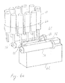
- Fig. 2 is a perspective view of an exemplary hermetically sealed second electron beam emitter 36 for sterilizing the exterior of ready-to-fill packaging containers 12.
- the purpose of the drawing is simply to illustrate the basic components of the emitter, and it should be emphasized that the purpose is not to provide a true constructional drawing or in any other way limit the present invention.
- the main component of the electron beam emitter is the tubular body 38, which has an elongate shape.
- An electron exit window 40 provides an outlet for electrons from the vacuum inside the tubular body 38.
- the exit window 40 in turn comprises subassemblies not relevant for the present invention, yet having the properties of providing an outlet window for electrons while preserving vacuum inside the body 38.
- a proximal end of the body 38 comprises an assembly including electrical connections 42.
- Fig. 3 shows the emitter 36 without the tubular body 38, and a cathode 44 is shown.
- the cathode 44 comprises a cathode housing 46, which is also shown in the very schematic cross section of Fig. 4 .
- the cathode housing 46 is formed as a semi-annular shell, the open side of which is covered by a control grid 48. Inside the annular shell of the cathode housing 46 one or more filaments 50 (see Fig. 4 ) are arranged, extending from a proximal end of the cathode housing 46 to a distal end thereof.
- an electron beam is generated by heating the filament 50, using a current, and by accelerating the electron towards the electron exit window 40 by means of a high-voltage potential between the cathode housing 46 and the exit window 40 (being the anode).
- the high-voltage potential is created by for example connecting the cathode housing to a power supply and by connecting the tubular body to ground.
- an electrical potential also to the control grid 48 the emission of electrons may be further controlled. This can be achieved by connecting the control grid 48 to a separate power supply.
- the second electron beam emitter 36 has an accelerating voltage in the order of 95 kV. This voltage results in a kinetic (motive) energy of 95 keV in respect of each electron. However, another voltage can be chosen, for example in the interval 75-150 kV.
- the control grid 48 comprises a flat perforated surface comprising a pattern of openings or through-holes for passage of electrons.
- the cathode housing 46 and the control grid 48 are mounted together by means of attachment means 52. If there is a difference in electrical potential between the cathode housing 46 and the grid 48 said attachment means 52 are preferably electrical isolator elements.
- Free longitudinal end portions 54 of the control grid 48 are bent in a direction towards each other, i.e. in a lateral direction being perpendicular to the extension of the longitudinal end portions, to form bulge-like shapes for the formation of electron beam shaping electrodes.
- Such electrodes are sometimes referred to as "Wehnelt” electrodes.
- the bulge-like shape will assist in the generation of a smooth predictable electrical field to the benefit of performance of the electron beam emitter. They help shaping the electric field so that the electrons will hit the exit window 40 in an essentially right angle, i.e. in a direction essentially perpendicular to the plane of the exit window 40.
- the described cathode is fitted into the electron beam emitter as shown in Fig. 3 .
- the proximal end as well as the distal end of the cathode housing 46 comprises electrical connections as well as physical suspensions for the filament 50. At the distal end this arrangement is housed inside or covered with a dome-shaped cap 54. At its proximal end the cathode housing 46 is suspended to the elongate body and the suspension is encapsulated by an annular cover 58.
- FIGs 5a-5e show a first embodiment illustrating the general concept of the invention.
- a sterilization chamber of a filling machine is shown.
- the sterilization chamber is denoted with reference numeral 60.
- at least one first electron beam emitter 10 is arranged on a first conveying means (not shown).
- the first electron beam emitter 10 is for example of the type described above in relation to Figure 1a , and it is adapted for sterilization of at least the interior of the packaging container 12.
- the interior of the packaging container 12 is all inside surfaces of the packaging container.
- the sterilization chamber 60 is not kept sterile due to the fact that non-sterilized packaging containers 12 are continuously fed into the chamber for the purpose of becoming sterilized.
- the aseptic chamber 62 is arranged downstream the sterilization chamber 60, i.e. the packaging containers 12 will first enter the sterilization chamber 60 and then subsequently enter the aseptic chamber 62.
- the aseptic chamber 62 comprises stations (not shown) in which the packaging container 12 is adapted to be filled with a product, such as for example a beverage, and sealed.
- a product such as for example a beverage
- the sealing station comprises sealing bars for heatsealing the packaging material.
- the sealing station instead comprises a capping station.
- the interface region 64 is an open passage between the sterilization chamber 60 and the aseptic chamber 62.
- at least one second electron beam emitter 36 adapted for sterilization of at least the exterior of the packaging container 12.
- the exterior of the packaging container is all surfaces on the outside of the packaging container.
- second electron beam emitters 36 arranged in the interface region 64. They are arranged opposite each other, with the interface region 64 in between them, such that the packaging containers can pass through it. Further, their electron exit windows 40 are facing the interface region 64 such that the second electron beam emitters 36 are adapted to sterilize the exterior of the packaging containers when those are passed from the sterilization chamber 60 to the aseptic chamber 62 through the interface region 64.
- the electron beam generated by each of the second electron beam emitters 36 during operation form a combined electron cloud.
- the boundary of the cross section of that electron cloud is shown with dashed line I in Figure 5a .
- the electron cloud of one of the second electron beam emitters 36 is shown in Figure 5b and 5c , and is denoted II. It has a substantially circular cross section.
- the combined electron cloud I fills the interface region 64 forming an aseptic lock.
- the electron cloud I has an extension in three dimensions and forms a volume being large enough to at least cover the interface region 64.
- Figure 5e illustrates the volume of the interface region 64. The longer sides are approximately as large as the longitudinal extension of the electron exit window 40 of the second electron beam emitter.
- the volume of the electron cloud I is at least as large as the volume of the interface region 64, i.e. the cloud I at least fills the volume of Fig. 5e .
- the electron beams have at least enough energy to kill any microbiological material travelling through the interface region 64 at the same velocity as the velocity of the packaging containers or of any particle or air flow travelling through the same.
- the dose rate at the boundary of the electron cloud II is approx. 400-800 kGy/s. In the centre of the electron cloud the dose rate is higher.
- the size of the interface region 64 and the energy of the second electron beam emitter will need to be matched for each application such that the electron cloud at least covers the interface region and such that the minimum dose rate of the electron cloud I is enough to kill any microbiological particles passing the interface region 64 at a chosen maximum velocity.
- the electron cloud I i.e. the aseptic lock
- the electron cloud I is suitable for killing microbiological material within it's direct reach.
- the innermost interior of the packaging container 12 is not within direct reach, it is "shadowed" by the packaging material of the packaging container.
- Figure 5a shows the case in which the interior of the packaging container 12 is sterile upon entering the aseptic chamber 62.
- the electron cloud III of the first electron beam emitter 10 upon finalising the interior sterilization of the packaging container 12, at least partly overlap the electron cloud I of the second electron beam emitters, it can then be ensured that every portion of the packaging container 12 reaching the inside of the aseptic chamber 62 has been fully sterilized.
- the first electron beam emitters 10 and any conveying means need not enter the aseptic chamber 62.
- a cross section of the electron cloud III of the first electron beam emitter 10 is represented by a dashed line III, see Figure 5d .
- the cross sectional shape is circular or droplet-shaped.
- the electron cloud is axis-symmetrical and the cloud volume is thereby spherical or droplet-shaped.
- the electron beam has at least enough energy to kill any microbiological material travelling through the interface region at the same velocity as the velocity of the packaging containers or of any air flow travelling through the same.
- the dose rate at the boundary of the electron cloud III is approx. 1000-1600 kGy/s. In the centre of the electron cloud the dose rate is higher.
- the energy of the first electron beam emitter 10 needs to be matched with the sterilization time available and the packaging container size and shape.
- the electron cloud III forms an aseptic lock, but an aseptic lock inside the packaging container 12 during sterilization. Although most of the interior sterilization is made in the sterilization chamber 60, not being fully sterile as compared with the aseptic chamber 62, the electron cloud III is able to form an aseptic lock inside the packaging container. No dirt or microbiological material or particle can manage to travel through the cloud III and into the sterilized interior of the packaging container 12. The volume of the electron cloud III of the first emitter 10 covers the opening 34 of the packaging container. Hence, the sterility of the interior, below the electron cloud III, can be assured even during the time when the packaging container 12 is still in the sterilization chamber 60.
- Figure 5a shows the moment when the packaging container 12 is on its way through the interface region 64 between the two opposite second electron beam emitters 36.
- the packaging container 12 is on its way to the first position, meaning that the packaging container and the first electron beam emitter 10 will soon no longer be engaged with each other.
- the uppermost end of the packaging container being the open bottom end 34 of the packaging container 12, is still affected by the electron cloud III from the first electron beam emitter 10, although the first electron beam emitter 10 is no longer inside the packaging container 12.
- the packaging container 12 has been passed into the electron cloud I of the second beam emitters 36, and most of the exterior of the packaging container 12 has already been sterilized by the electron cloud I of the second beam emitters 36.
- the packaging container 12 is moved through the interface region 64 with its top and screw cap first.
- Figure 5a it can be seen that the electron cloud III of the first electron beam emitter 10 partly overlaps the electron cloud I of the second electron beam emitters 36. The overlapping is created in the area of the uppermost end of the packaging container, i.e. at the open bottom end 34 of the packaging container 12.
- the packaging container 12 reaches the aseptic chamber 62 it is fully sterilized.
- the sterilization chamber 60 is provided with first conveying means adapted to push the packaging container 12 at least partly through the aseptic lock in the interface region 64.
- first conveying means adapted to push the packaging container 12 at least partly through the aseptic lock in the interface region 64.
- second conveying means (not shown) that will receive the packaging container 12.
- the packaging container When received in the second conveying means the packaging container will be released by the first conveying means.
- the first conveying means is releasing the packaging container before the second conveying means grip it, having the packaging container falling freely for a moment.
- the first conveying means in the sterilization chamber 60 is arranged separately from the second conveying means.
- the first and second conveying means are separately arranged one on each side of the interface region 64.
- the first conveying means are gripping the packaging container on the exterior surface.
- the first conveying means must release the packaging container within the electron cloud I of the second electron beam emitters 36, or within reach of the electron cloud III of the first electron beam emitter 10, to have also the contact surface sterilized.
- the contact surface is the surface at which the gripping means has gripped the packaging container.
- the first conveying means are gripping the packaging container on its interior surface. To obtain a fully sterilized packaging container the first conveying means must release the packaging container within the electron cloud III of the first electron beam emitter 10.
- Figures 6a-6h show a more detailed, second embodiment of the invention.
- some of the reference numerals used for describing the first embodiment will be re-used for similar features.
- first conveying means comprises a drive belt or chain on which the first electron beam emitters 10 are attached.
- the belt or chain is just illustrated by line 66.
- This belt or chain is adapted to convey each packaging container synchronously with a first electron beam emitter 10, keeping a longitudinal axis of the first electron beam emitter aligned with a longitudinal axis of the packaging container, see common longitudinal axis a in Fig. 1a .
- the drive belt or chain 66 of the first conveying means is shaped with two opposite linear portions and two opposite curved portions, see Fig. 6b .
- the movement of the belt or chain is continuous, but alternatively it is intermittent. The direction of the movement is illustrated by the arrow A.
- the first conveying means is adapted to displace the packaging container from a sterilization chamber in-feed position 68 to an out-feed position, the out-feed position being near the interface region 64, at a position slightly above.
- the in-feed position 68 is located at one of the linear portions of the drive belt or chain 66, whereas the out-feed position is located at the other linear portion, see Fig. 6b .
- the first electron beam emitter 10 is adapted to sterilize the interior of the packaging container at least during a portion of the displacement from the sterilization in-feed position 68 to the out-feed position.
- the first conveying means comprises gripping means, not shown, adapted to grip the packaging container at the in-feed position 68.
- the packaging container is there started being displaced towards the first electron beam emitter. Since the first electron beam emitter 10 is aligned with the opening 34 of the packaging container 12 the electron beam emitter 10 is received in the packaging container 12. Hence, sterilization of the interior of the packaging container is commenced.
- the fully engaged second position is shown in Fig. 1a . In that position the innermost area of the packaging container 12 may be sterilized, in this case a top portion 70 of the packaging container 12.
- the interior sterilization cycle is completed when the packaging container 12 reaches the out-feed position near the interface region 64.
- the packaging container is retracted, or has already been retracted from the second position back to the first position.
- the packaging container is then ready to be fed out from the sterilization chamber and into the aseptic chamber 62.
- the packaging conveying means may comprise a cam curve, servo motor or similar that guides the gripping means in the vertical direction upon rotation of the belt or chain.
- the gripping means are preferably gripping the packaging container near the opening 34, on the outside surface, by for example a clamping force.
- the gripping means as such are not the focus of this invention, they will not be described further.
- the out-feed position is, as mentioned before, arranged near the interface region 64, slightly above it.
- two second electron beam emitters 36 are arranged on each side of the opening, parallel to the longitudinal direction of the opening. They are arranged opposite each other with their electron beam exit windows 40 facing each other and the interface region 64. Either the planes of the electron exit windows 40 are parallel to each other, or slightly inclined in relation to each other as shown in Fig. 6c . In the latter case there is an angle ⁇ between the two electron exit windows 40.
- Figure 6b shows a top view of the interface region 64, and the two second electron beam emitters 36.
- the electron exit windows 40 are shown as being parallel to each other.
- the interface region 64 being the only entrance to the aseptic chamber 62 from the sterilization chamber 60, will during operation be totally covered by the electron cloud I of the second emitters.
- Figures 6d-6g show a cross section through the interface region 64, and a portion of the aseptic chamber 62. Hence, only one second electron beam emitter 36 is shown. The figures further show one first electron beam emitter 10 and one packaging container 12. By means of the Figures 6d-6g the movement of the first electron beam emitter 10 and the packaging container 12 through the interface region 64 will be described.
- Figure 6d shows the second postion in which the packaging container 12 is fully engaged with the first electron beam emitter 10.
- the first electron beam emitter 10 and the packaging container 12 have moved from the in-feed position 68 to a position slightly to the left of the interface region 64. Further, as can be seen in the figure, the first electron beam emitter 10 and the packaging container 12 is positioned slightly above the second electron beam emitters 36. Two walls of the aseptic chamber 62 are shown and denoted 72 and 74.
- the first electron beam emitter 10 together with the packaging container 12 has moved a distance to the right by means of the belt or chain of the first conveying means.
- the conveying means has started to vertically displace the packaging container 12 downwards in relation to the first electron beam emitter 10, from the second position to a position closer to the first position.
- the interior sterilization is on-going.
- the downward movement has further displaced the packaging container 12 into the electron cloud I of the second electron beam emitters 36, and the packaging container top 70, comprising the screw cap, is already through the interface region 64 and in the aseptic chamber 62. That portion has been sterilized on the outside by the second electron beam emitters 36.
- the first electron beam emitter 10 and the packaging container 12 have been moved further to the right.
- the first electron beam emitter 10 is finalizing the interior sterilization, i.e.
- the gripping means of the first conveying means positioned in the sterilization chamber 60, has released the packaging container 12, i.e. it is no longer gripping the packaging container.
- the gripping means is not passing the interface region 64 in this embodiment.
- the second conveying means, not shown, of the aseptic chamber 62 is within reach of the packaging container 12 and has taken over the gripping of the packaging container.
- Figure 6g shows a moment in which the packaging container 12 is fully sterilized and has been conveyed to the right in the figure by means of the second conveying means.
- the upper wall portion 72 of the aseptic chamber 62 is protecting the packaging container 12.
- the first electron beam emitter 10 is conveyed, by the first conveying means, back to the in-feed position.
- the first electron beam emitter 10 moves past a sensor (not shown) for measurement of at least one dose control parameter of the electron beam, such as for example the dose rate (kGy/s).
- FIGS 7a-7d show a more detailed, third embodiment of the invention.
- this third embodiment some of the reference numerals used for describing the second embodiment will be re-used for similar features. Only the differences between the third and second embodiment will be described.
- Figure 7a shows a sterilization device provided with several first electron beam emitters 10 of the type used for interior sterilization of packaging containers 12. Such first electron beam emitters 10 were described above with reference to Fig. 1a .
- the first electron beam emitters 10 are provided to first conveying means.
- the first conveying means comprises a rotatable carrier, shown as a line 76.
- the rotatable carrier is, in this embodiment, a wheel and is rotatable round a centre shaft, here illustrated as a dash-dotted line b.
- the direction of the rotation is illustrated by the arrow B and the rotatable movement is continuous.
- the first emitters 10 are equally distributed to the periphery of the carrier 76, and are fixed to the carrier so that they are being carried along when the carrier 76 rotates.
- the transportation of the packaging containers 12 is made in a direction transverse to the longitudinal extension of the emitters 10.
- the circle of Figure 7b shows, very schematically, the transportation path of the packaging container and the first electron beam emitter.
- the first conveying means is adapted to convey the packaging container from an in-feed position 78 in the sterilization chamber 60 to an outfeed position, said out-feed position being close to the interface region 64 towards the aseptic chamber 62.
- the conveying of the packaging container is made synchronously with the carrier revolution movement and in alignment with the electron beam emitter 10.
- a longitudinal centre axis of the packaging container is aligned with a longitudinal centre axis of the electron beam emitter, see common axis a in Fig. 1a .
- the opening 34 in the packaging container 12 is concentric with the longitudinal centre axis of the packaging container.
- the first conveying means is being further adapted to vertically displace the packaging container 12 in relation to the first electron beam emitter 10.
- the electron beam emitters 10 are arranged stationary in the carrier 76 and cannot move towards the packaging container. Due to the heavy weight, the fragile electron exit window and the high voltage connections it is an advantage to have the first electron beam emitters 10 stationary, and move the packaging containers 12.
- the first conveying means displaces the packaging container 12 between a first position in which the packaging container 12 and the electron beam emitter 10 are not engaged with each other and a second position in which the packaging container 12 and the electron beam emitter 10 are fully engaged with each other.
- the packaging container 12 and the electron beam emitter 10 are engaged the packaging container 12 has been raised to a position in which it surrounds the electron beam emitter 10 and the electron beam emitter 10 is sterilizing the interior of the packaging container.
- the packaging container is positioned underneath the electron beam emitter, i.e. the packaging container has not started to surround the emitter 10, or has just been displaced down from the engaged position.
- the packaging container 12 is positioned in the first position, i.e. not in engagement with the electron beam emitter 10.
- the packaging containers 12 are supplied to the sterilization device in the sterilization chamber 60.
- Each packaging container 12 is aligned with a corresponding electron beam emitter 10 and is gripped by means of gripping means (not shown).
- the gripping means is comprised in the first conveying means.
- the gripping means are attached to a drive belt or chain (not shown).
- the gripping means preferably grips the packaging container 12 in the top portion 70.
- the gripping means displaces the packaging container 12 towards the first electron beam emitter 10 for performing interior sterilisation.
- Figures 7a and 7b further show two second electron beam emitters 36 for example of the type described in relation to Figs. 2-4 . Similar to the arrangement of the two second electron beam emitters of the second embodiment, these two electron beam emitters 36 are arranged one on each side of the interface region, parallel to the longitudinal direction of the opening. They are arranged opposite each other with their electron beam exit windows 40 facing each other and the interface region. The planes of the electron exit windows are parallel to each other, but may alternatively be inclined as described in relation to Fig. 6c .
- Figure 7a further shows a part of the aseptic chamber 62.
- the only entrance to the aseptic chamber 62 from the sterilization chamber 60 is the interface region 64.
- Some of the walls, together denoted 80, needed towards the sterilization chamber 60 are shown in figure. It is however to be understood that not all necessary walls are shown, and that the aseptic chamber 62 is closed except for the opening 64 towards the sterilization chamber 60 and a packaging container outlet (not shown) for out-feed of finished packaging containers 12.
- Figures 7c show a cross section through the opening in the interface region 64. Hence, only one second electron beam emitter 36 is shown. The figure further show two subsequent packaging containers 12 and one first electron beam emitter 10.
- the packaging containers 12 When the packaging containers 12 has reached the position shown in Figure 7a it has been conveyed from the in-feed position 78 and almost to the out-feed position, i.e. the interface region 64.
- the packaging container 12 is being displaced downwards by the gripping means, from the second position to the first position, and the interior sterilization is on-going.
- Figure 7c the left packaging container 12 has been displaced further downwards and the interior sterilization is about to be finalised. Only the electron cloud III of the first electron beam emitter 10 is engaged with the opening 34 in the bottom end of the packaging container 12. At the same time the packaging container 12 as well as the first electron beam emitter 10 has been conveyed closer to the out-feed position, i.e. to the right in the figure and i.e. closer to the opening 64 towards the aseptic chamber 62. When the left packaging container 12 is moved to the right into the electron cloud I of the second electron beam emitters 36 the electron cloud III of the first electron beam emitter 10 will be partly overlapping the electron cloud I of the second electron beam emitters 36.
- the gripping means Upon further displacement to the right, see the right packaging container 12, the gripping means will raise the packaging container so that it will move through the opening and the electron cloud I of the second electron beam emitters 36, i.e. through the aseptic lock, and become sterile on its outside surface.
- the gripping means of the first conveying means releases the packaging container, and second conveying means (not shown) in the aseptic chamber 62 grips the packaging container and takes over the conveyance. In Figure 7c no walls of the aseptic chamber is shown.
- Figure 7d shows the interface region 64, i.e. the passage into the aseptic chamber 62 and a portion of a packaging container 12 being raised through the interface region.
- the figure also shows the walls 80 around the opening 64 as well as a ditch 82 in the lowermost wall portion 84 for receiving the top portion 70 of the packaging container 12 upon further movement up through the opening and into the aseptic chamber 62.
- the invention comprises a method of sterilizing packaging containers with electron beams in a filling machine.
- the method has to a large extent already been described in relation to the various embodiments, and will only be summarized in the following.
- the method comprises the steps of sterilizing at least the interior of the packaging container with a first electron beam emitter arranged in a sterilization chamber, and sterilizing at least the exterior of the packaging container with a second electron beam emitter.
- the step of sterilizing the exterior of the packaging container is performed in an interface region, said interface region forming an opening from the sterilization chamber to an aseptic chamber.
- An electron cloud emitted from the second electron beam emitter during operation is adapted to form an aseptic lock at least covering the opening in the interface region.
- the method further comprises the step of finalizing the interior sterilization such that an electron cloud emitted from the first electron beam emitter partly overlaps the electron cloud emitted from the second electron beam emitter.
- two second electron beam emitters are shown opposite each other.
- there is only one second electron beam emitter and the packaging container is made to rotate approximately one round around its own longitudinal axis when passing through the interface region.
- the opening between the sterilization chamber and the aseptic chamber should not be larger than that the electron cloud, generated by the single second electron beam emitter, can cover the opening.
- the sterilization device has been described and illustrated in a schematic way in the above described embodiments and in the drawings. Only parts of the sterilization device being involved in the invention has been described, but it is to be understood that the sterilization device comprises also additional parts such as drive units for driving the first and second conveying means, and irradiation shielding enclosing the sterilization device for securing that electrons and x-rays are not spread to the environment outside of the device.
Abstract
Description
- The present invention relates to a sterilization device for sterilizing packaging containers with electron beams in a filling machine. The invention also relates to a method.
- Within the food industry, it is common practice to pack liquid and partly liquid food products in packaging containers manufactured from a packaging laminate comprising a core layer of paper or paperboard and one or more barrier layers of, for example, polymer material or aluminium foil.
- An increasingly common packaging type is the "carton bottle" manufactured in a filling machine in that packaging blanks of the above-described packaging laminate are formed and sealed as a sleeve. Said sleeve is closed in one end in that a top of thermoplastic material is injection moulded directly on the sleeve end portion. The sheets of packaging laminate may be cut from a magazine reel of packaging laminate.
- When the top is finished the packaging container is ready to be filled with product through the still open bottom, and then sealed and finally folded. Before the filling operation the packaging container undergoes treatment. If distribution and storage is to be made in chilled temperature the packaging container is disinfected, whereas if distribution and storage is to be made in ambient temperature, the packaging container needs to be sterilized. A conventional way of sterilizing a ready-to-fill packaging container is to use hydrogen peroxide, preferably in gas phase.
- Another way to sterilize such packaging containers is to irradiate it by means of a low voltage electron beam emitted from an electron beam emitter. An example of linear irradiation by electron beam of ready-to-fill packaging containers is disclosed in the international patent publication
WO 2005/002973 . The electron beam emitter is cylindrical with an electron exit window positioned at one of the distal ends. The packaging container is lifted to surround the electron beam emitter during the sterilization cycle. Other examples of irradiation of packaging containers, in these cases PET bottles, are described in for exampleWO 2011/011079 andEP 2 371 397 . In these systems emitters are used having a diameter small enough to be passed through a neck portion of the bottles. - The present invention relates to a sterilization device for sterilizing packaging containers with electron beams in a filling machine. The sterilization device comprises at least one first electron beam emitter adapted for sterilization of at least the interior of the packaging container and at least one second electron beam emitter adapted for sterilization of at least the exterior of said packaging container. A sterilization chamber in which the first electron beam emitter is adapted to sterilize the interior of the packaging container. The at least one second electron beam emitter is positioned such that an electron exit window thereof is facing an interface region, said interface region forming an opening from the sterilization chamber to an aseptic chamber. An electron cloud emitted from the at least one second electron beam emitter during operation is adapted to form an aseptic lock at least covering the interface region.
- In one embodiment an electron cloud emitted from the first electron beam emitter, upon finalisation of the interior sterilization of the packaging container, is adapted to be partly overlapping the electron cloud emitted from the at least one second electron beam emitter.
- In one or more embodiments the sterilization chamber comprises at least first conveying means, and the aseptic chamber comprises at least second conveying means, and the first and second conveying means are separately arranged one on each side of the interface region.
- In one or more embodiment the first conveying means is adapted to push the packaging container at least partly through the aseptic lock in the interface region, and release the packaging container when it has been received by the second conveying means on the other side of the aseptic lock.
- In one or more embodiments the first electron beam emitter and the packaging container are adapted to perform a mutual relative movement during which the interior sterilization of the packaging container takes place.
- In one or more embodiments the first conveying means is adapted to displace the packaging container in relation to the first electron beam emitter between a first position in which the packaging container and the first electron beam emitter are not engaged with each other and a second position in which the packaging container and the first electron beam emitter are fully engaged with each other.
- In one or more embodiments said at least one second electron beam emitter being adapted to sterilize the exterior of the packaging container when passing the packaging container from the sterilization chamber to the aseptic chamber, through the interface region, such that the packaging container reaching the aseptic chamber is fully sterilized on its exterior.
- In one or more embodiments it comprises two second electron beam emitters, arranged opposite each other with their electron exit windows facing each other and the interface region, in such a way that the packaging containers can pass in between them.
- In one or more embodiments the first electron beam emitter is arranged in the first conveying means, and the first conveying means is adapted to convey the packaging container synchronously with the first electron beam emitter, keeping a longitudinal axis of the first electron beam emitter aligned with a longitudinal axis of the packaging container.
- In one or more embodiments the first conveying means is adapted to displace the packaging container from a sterilization chamber in-feed position to an out-feed position, the out-feed position being in the vicinity of the interface region, and the first electron beam emitter is adapted to sterilize the interior of the packaging container at least during a portion of the displacement between the sterilization in-feed position to the out-feed position.
- In one or more embodiments the first conveying means is provided with more than one first electron beam emitter.
- In one or more embodiments the aseptic chamber comprises stations in which the packaging container is adapted to be filled with product and sealed.
- The invention also comprises a method of sterilizing packaging containers with electron beams in a filling machine. The method comprises the steps of sterilizing at least the interior of the packaging container with a first electron beam emitter arranged in a sterilization chamber. It further comprises the step of sterilizing at least the exterior of the packaging container with at least one second electron beam emitter. The step of sterilizing the exterior of the packaging container is performed in an interface region, said interface region forming an opening from the sterilization chamber to an aseptic chamber, and wherein an electron cloud emitted from the at least one second electron beam emitter during operation is adapted to form an aseptic lock at least covering the interface region.
- In one or more embodiments the method comprises the step of finalizing the interior sterilization such that an electron cloud emitted from the first electron beam emitter partly overlaps the electron cloud emitted from the at least one second electron beam emitter.
- In the following, an embodiment of the invention will be described in greater detail, with reference to the enclosed schematic drawings, in which:
-
Fig. 1a is a view of a packaging container and an exemplary first electron beam emitter, for sterilizing the interior of the packaging container, in a fully engaged sterilization position, -
Fig. 1b is a view of an alternative packaging container and first electron beam emitter, -
Fig. 2 is a perspective view of a second electron beam emitter for sterilizing the exterior of the packaging container, -
Fig. 3 is a perspective view of a cathode which may be used in the electron beam emitter ofFig. 2 , -
Fig. 4 is a cross section of the cathode ofFig. 3 , -
Fig. 5a is a cross sectional view illustrating a first embodiment of the invention, showing the general principle of the invention, -
Fig. 5b is a schematic side view of a second electron beam emitter and its electron cloud, -
Fig. 5c is a schematic front view of the second electron beam emitter ofFig. 5b and its electron cloud, -
Fig. 5d is a view of a first electron beam emitter and its electron cloud, -
Fig. 5e is a view of the volume of the interface region, -
Fig. 6a is a perspective view illustrating a second embodiment of the invention, -
Fig. 6b is a top view illustrating portions of the second embodiment of the invention, -
Fig. 6c is a side view of two second electron beam emitters having electron exit windows being inclined relative each other, -
Figs. 6d-6g are a cross sectional views of the aseptic chamber, a first electron beam emitter, a second electron beam emitter and a packaging container of the second embodiment, -
Fig. 7a is a perspective view of a third embodiment of the invention, -
Fig. 7b is top view illustrating portions of the third embodiment, -
Fig. 7c is a side view of a first electron beam emitter, a second electron beam emitter and two packaging containers of the third embodiment, and -
Fig. 7d is a perspective view of portions of the aseptic chamber of the third embodiment. - In the following, and with reference to
Figure 1a , an exemplary firstelectron beam emitter 10 for sterilizing the interior of ready-to-fill packaging containers 12 and the concept of electron beam sterilization will be briefly described. - The
electron beam emitter 10 comprises anelectron generator 14 for emitting a substantiallycircular electron beam 16 along a path. Theelectron generator 14 is enclosed in a hermetically sealedvacuum chamber 18. Saidvacuum chamber 18 is provided with anelectron exit window 20. - The
electron generator 14 comprises acathode housing 22 and afilament 24. Optionally, theelectron generator 14 also comprises acontrol grid 26. In use, anelectron beam 16 is generated by heating thefilament 24. When an electrical current is fed through thefilament 24, the electrical resistance of thefilament 24 causes the filament to be heated to a temperature in the order of 2000°C. This heating causes thefilament 24 to emit a cloud of electrons. The electrons are accelerated towards theelectron exit window 20 by means of a high-voltage potential between thecathode housing 22 and the exit window 20 (being the anode). Further, the electrons pass through theelectron exit window 20 and continue towards the target area, i.e. in this case the inside of thepackaging container 12. - The high-voltage potential is created by for example connecting the
cathode housing 22 and thefilament 24 to apower supply 28 and by connecting the vacuum chamber to ground 30. The firstelectron beam emitter 10 is generally denoted low voltage electron beam emitter if the voltage is below 300 kV. In the disclosed design the accelerating voltage is in the order of 95 kV. This voltage results in a kinetic (motive) energy of 95 keV in respect of each electron. However, another voltage can be chosen, for example in the interval 75-150 kV. By applying an electrical potential also to thecontrol grid 26 the emission of electrons may be further controlled. If a separate and variable electrical potential is applied to thecontrol grid 26 it makes it possible to use thecontrol grid 26 for active shaping of the generated electron beam. For these purposes thecontrol grid 26 may be electrically connected to aseparate power supply 32. - The
filament 24 can be made of tungsten. Thegrid 26, placed between thefilament 24 and an electronbeam exit window 20 provided with a number of openings and is used for diffusing theelectron beam 16 into a more uniform beam, and for focusing theelectron beam 16 towards the target area. - The
emitter 10 is, as mentioned, further provided with anelectron exit window 20. Thewindow 20 can be made of a metallic foil, such as for example titanium, and can have a thickness in the order of 4-12 µm. A supporting net (not shown) formed of aluminum or copper supports the foil from inside thevacuum chamber 18. The electrons are exiting thevacuum chamber 18 through theexit window 20. - In this embodiment the
vacuum chamber 18 is made up of twocylindrical bodies cylindrical body 18a is provided with theelectron exit window 20. The diameter of saidfirst body 18a is small enough to be inserted into the ready-to-fill packaging container 12, the cross section of said first body is dimensioned such that it can be guided through anopening 34 of thepackaging container 12. Thesecond body 18b is provided with the electron beam generator14, and the diameter of saidsecond body 18b is larger than thefirst body 18a. The diameter of the emittedelectron beam 16, while still inside theemitter 10, is smaller than the diameter of thefirst body 18a. - In
Figure 1a theopening 34 of the packaging container is an open bottom end, which after filling will be sealed and folded to form a substantially flat bottom surface. It should however be understood that the opening, through which the first electron beam device is received, may in other embodiments be arranged in the top of the packaging container, constituting a neck or spout portion of the packaging container.Figure 1b illustrates such. The neck or spout portion will, after filling, be sealed by for instance a screw cap. -
Fig. 2 is a perspective view of an exemplary hermetically sealed secondelectron beam emitter 36 for sterilizing the exterior of ready-to-fill packaging containers 12. The purpose of the drawing is simply to illustrate the basic components of the emitter, and it should be emphasized that the purpose is not to provide a true constructional drawing or in any other way limit the present invention. - The main component of the electron beam emitter is the
tubular body 38, which has an elongate shape. Anelectron exit window 40 provides an outlet for electrons from the vacuum inside thetubular body 38. Theexit window 40 in turn comprises subassemblies not relevant for the present invention, yet having the properties of providing an outlet window for electrons while preserving vacuum inside thebody 38. A proximal end of thebody 38 comprises an assembly includingelectrical connections 42. -
Fig. 3 shows theemitter 36 without thetubular body 38, and acathode 44 is shown. Thecathode 44 comprises acathode housing 46, which is also shown in the very schematic cross section ofFig. 4 . Thecathode housing 46 is formed as a semi-annular shell, the open side of which is covered by acontrol grid 48. Inside the annular shell of thecathode housing 46 one or more filaments 50 (seeFig. 4 ) are arranged, extending from a proximal end of thecathode housing 46 to a distal end thereof. In use, an electron beam is generated by heating thefilament 50, using a current, and by accelerating the electron towards theelectron exit window 40 by means of a high-voltage potential between thecathode housing 46 and the exit window 40 (being the anode). The high-voltage potential is created by for example connecting the cathode housing to a power supply and by connecting the tubular body to ground. By applying an electrical potential also to thecontrol grid 48 the emission of electrons may be further controlled. This can be achieved by connecting thecontrol grid 48 to a separate power supply. - The second
electron beam emitter 36 has an accelerating voltage in the order of 95 kV. This voltage results in a kinetic (motive) energy of 95 keV in respect of each electron. However, another voltage can be chosen, for example in the interval 75-150 kV. - The
control grid 48 comprises a flat perforated surface comprising a pattern of openings or through-holes for passage of electrons. The open side of thecathode housing 46, carrying thecontrol grid 48, should for obvious reasons be facing theelectron exit window 40. Thecathode housing 46 and thecontrol grid 48 are mounted together by means of attachment means 52. If there is a difference in electrical potential between thecathode housing 46 and thegrid 48 said attachment means 52 are preferably electrical isolator elements. Freelongitudinal end portions 54 of thecontrol grid 48 are bent in a direction towards each other, i.e. in a lateral direction being perpendicular to the extension of the longitudinal end portions, to form bulge-like shapes for the formation of electron beam shaping electrodes. Such electrodes are sometimes referred to as "Wehnelt" electrodes. The bulge-like shape will assist in the generation of a smooth predictable electrical field to the benefit of performance of the electron beam emitter. They help shaping the electric field so that the electrons will hit theexit window 40 in an essentially right angle, i.e. in a direction essentially perpendicular to the plane of theexit window 40. - The described cathode is fitted into the electron beam emitter as shown in
Fig. 3 . The proximal end as well as the distal end of thecathode housing 46 comprises electrical connections as well as physical suspensions for thefilament 50. At the distal end this arrangement is housed inside or covered with a dome-shapedcap 54. At its proximal end thecathode housing 46 is suspended to the elongate body and the suspension is encapsulated by anannular cover 58. -
Figures 5a-5e show a first embodiment illustrating the general concept of the invention. InFig. 5a a sterilization chamber of a filling machine is shown. The sterilization chamber is denoted withreference numeral 60. In thesterilization chamber 60 at least one firstelectron beam emitter 10 is arranged on a first conveying means (not shown). The firstelectron beam emitter 10 is for example of the type described above in relation toFigure 1a , and it is adapted for sterilization of at least the interior of thepackaging container 12. The interior of thepackaging container 12 is all inside surfaces of the packaging container. Thesterilization chamber 60 is not kept sterile due to the fact thatnon-sterilized packaging containers 12 are continuously fed into the chamber for the purpose of becoming sterilized. However, near thesterilization chamber 60 there is provided anaseptic chamber 62. Theaseptic chamber 62 is arranged downstream thesterilization chamber 60, i.e. thepackaging containers 12 will first enter thesterilization chamber 60 and then subsequently enter theaseptic chamber 62. During production ofpackaging containers 12 the environment in theaseptic chamber 62 should be sterile, i.e. free from dirt and microbiological material. Theaseptic chamber 62 comprises stations (not shown) in which thepackaging container 12 is adapted to be filled with a product, such as for example a beverage, and sealed. Depending on which end of the packaging container that is open, the bottom as shown inFig. 1a , or the neck as shown inFig. 1b the sealing station may look different. In the case of filling into an open bottom end the sealing station comprises sealing bars for heatsealing the packaging material. In the case of filling through a spout in a neck region of a packaging container the sealing station instead comprises a capping station. Before thepackaging containers 12 have been sealed it needs to be ensured that the environment around them is sterile, that the packaging containers entering theaseptic chamber 62 from thesterilization chamber 60 are sterile, and that no contaminated air is allowed to escape into theaseptic chamber 62 from thesterilization chamber 60. - Between the
sterilization chamber 60 and theaseptic chamber 62 there is aninterface region 64 through which thepackaging containers 12 can pass from thesterilization chamber 60 to theaseptic chamber 62, i.e. theinterface region 64 forms anopening 64 between thesterilization chamber 60 and theaseptic chamber 62. Hence, theinterface region 64 is an open passage between thesterilization chamber 60 and theaseptic chamber 62. In the vicinity of theinterface region 64 there is provided at least one secondelectron beam emitter 36 adapted for sterilization of at least the exterior of thepackaging container 12. The exterior of the packaging container is all surfaces on the outside of the packaging container. - In this specific embodiment there are two second
electron beam emitters 36 arranged in theinterface region 64. They are arranged opposite each other, with theinterface region 64 in between them, such that the packaging containers can pass through it. Further, theirelectron exit windows 40 are facing theinterface region 64 such that the secondelectron beam emitters 36 are adapted to sterilize the exterior of the packaging containers when those are passed from thesterilization chamber 60 to theaseptic chamber 62 through theinterface region 64. - The electron beam generated by each of the second
electron beam emitters 36 during operation form a combined electron cloud. The boundary of the cross section of that electron cloud is shown with dashed line I inFigure 5a . The electron cloud of one of the secondelectron beam emitters 36 is shown inFigure 5b and5c , and is denoted II. It has a substantially circular cross section. The combined electron cloud I fills theinterface region 64 forming an aseptic lock. The electron cloud I has an extension in three dimensions and forms a volume being large enough to at least cover theinterface region 64.Figure 5e illustrates the volume of theinterface region 64. The longer sides are approximately as large as the longitudinal extension of theelectron exit window 40 of the second electron beam emitter. The volume of the electron cloud I is at least as large as the volume of theinterface region 64, i.e. the cloud I at least fills the volume ofFig. 5e . Within the boundaries of the electron cloud I, i.e. the aseptic lock, the electron beams have at least enough energy to kill any microbiological material travelling through theinterface region 64 at the same velocity as the velocity of the packaging containers or of any particle or air flow travelling through the same. Typically, for a secondelectron beam emitter 36 of the above described type, the dose rate at the boundary of the electron cloud II is approx. 400-800 kGy/s. In the centre of the electron cloud the dose rate is higher. The size of theinterface region 64 and the energy of the second electron beam emitter will need to be matched for each application such that the electron cloud at least covers the interface region and such that the minimum dose rate of the electron cloud I is enough to kill any microbiological particles passing theinterface region 64 at a chosen maximum velocity. - The electron cloud I, i.e. the aseptic lock, is suitable for killing microbiological material within it's direct reach. The innermost interior of the
packaging container 12 is not within direct reach, it is "shadowed" by the packaging material of the packaging container. Hence, to ensure that the sterile environment inside theaseptic chamber 62 is not contaminated through theinterface region 64 it is important that also the interior of the packaging containers is sterile when entering the aseptic lock, or that any still unsterile portion of the interior of the packaging container is protected by an electron cloud from the firstelectron beam emitter 10. -
Figure 5a shows the case in which the interior of thepackaging container 12 is sterile upon entering theaseptic chamber 62. This gives a simple mechanical solution since the firstelectron beam emitters 10 don't need to enter theaseptic chamber 62. By letting the electron cloud III of the firstelectron beam emitter 10, upon finalising the interior sterilization of thepackaging container 12, at least partly overlap the electron cloud I of the second electron beam emitters, it can then be ensured that every portion of thepackaging container 12 reaching the inside of theaseptic chamber 62 has been fully sterilized. In other words, by creating electron clouds I, III being partly overlapping it is ensured that any microbiological material on the inside surface of the packaging container cannot escape to the outside surface, or vice versa, without being killed. Yet, the firstelectron beam emitters 10 and any conveying means need not enter theaseptic chamber 62. - A cross section of the electron cloud III of the first
electron beam emitter 10 is represented by a dashed line III, seeFigure 5d . The cross sectional shape is circular or droplet-shaped. The electron cloud is axis-symmetrical and the cloud volume is thereby spherical or droplet-shaped. Within the dashed line III the electron beam has at least enough energy to kill any microbiological material travelling through the interface region at the same velocity as the velocity of the packaging containers or of any air flow travelling through the same. Typically, for a firstelectron beam emitter 10 of the above described type, the dose rate at the boundary of the electron cloud III is approx. 1000-1600 kGy/s. In the centre of the electron cloud the dose rate is higher. The energy of the firstelectron beam emitter 10 needs to be matched with the sterilization time available and the packaging container size and shape. - It should be pointed out that also the electron cloud III forms an aseptic lock, but an aseptic lock inside the
packaging container 12 during sterilization. Although most of the interior sterilization is made in thesterilization chamber 60, not being fully sterile as compared with theaseptic chamber 62, the electron cloud III is able to form an aseptic lock inside the packaging container. No dirt or microbiological material or particle can manage to travel through the cloud III and into the sterilized interior of thepackaging container 12. The volume of the electron cloud III of thefirst emitter 10 covers theopening 34 of the packaging container. Hence, the sterility of the interior, below the electron cloud III, can be assured even during the time when thepackaging container 12 is still in thesterilization chamber 60. -
Figure 5a shows the moment when thepackaging container 12 is on its way through theinterface region 64 between the two opposite secondelectron beam emitters 36. Thepackaging container 12 is on its way to the first position, meaning that the packaging container and the firstelectron beam emitter 10 will soon no longer be engaged with each other. Still, the uppermost end of the packaging container, being the openbottom end 34 of thepackaging container 12, is still affected by the electron cloud III from the firstelectron beam emitter 10, although the firstelectron beam emitter 10 is no longer inside thepackaging container 12. At the same time thepackaging container 12 has been passed into the electron cloud I of thesecond beam emitters 36, and most of the exterior of thepackaging container 12 has already been sterilized by the electron cloud I of thesecond beam emitters 36. Thepackaging container 12 is moved through theinterface region 64 with its top and screw cap first. InFigure 5a it can be seen that the electron cloud III of the firstelectron beam emitter 10 partly overlaps the electron cloud I of the secondelectron beam emitters 36. The overlapping is created in the area of the uppermost end of the packaging container, i.e. at the openbottom end 34 of thepackaging container 12. When thepackaging container 12 reaches theaseptic chamber 62 it is fully sterilized. - With
Figures 5a-5e the general principle of the aseptic lock has been described. By creating a sterile airflow through theinterface region 64, in a direction from theaseptic chamber 62 towards thesterilization chamber 60, the aseptic lock can be sustained even if thesecond beam emitters 36 are temporarily shut off. Of course the packaging container transport needs to be stopped as well, since no sterilization will take place. - What is not shown in
Figure 5a is that thesterilization chamber 60 is provided with first conveying means adapted to push thepackaging container 12 at least partly through the aseptic lock in theinterface region 64. In theaseptic chamber 62, on the other side of the aseptic lock, there are second conveying means (not shown) that will receive thepackaging container 12. When received in the second conveying means the packaging container will be released by the first conveying means. Alternatively, the first conveying means is releasing the packaging container before the second conveying means grip it, having the packaging container falling freely for a moment. - The first conveying means in the
sterilization chamber 60 is arranged separately from the second conveying means. The first and second conveying means are separately arranged one on each side of theinterface region 64. Hence, there is only necessary to machine-sterilize the second conveying means in theaseptic chamber 62. The first conveying means are gripping the packaging container on the exterior surface. To obtain a fully sterilized packaging container the first conveying means must release the packaging container within the electron cloud I of the secondelectron beam emitters 36, or within reach of the electron cloud III of the firstelectron beam emitter 10, to have also the contact surface sterilized. The contact surface is the surface at which the gripping means has gripped the packaging container. Alternatively, the first conveying means are gripping the packaging container on its interior surface. To obtain a fully sterilized packaging container the first conveying means must release the packaging container within the electron cloud III of the firstelectron beam emitter 10. -
Figures 6a-6h show a more detailed, second embodiment of the invention. In the following description of the seond embodiment some of the reference numerals used for describing the first embodiment will be re-used for similar features. - In this second embodiment several first
electron beam emitters 10, of the type described above with reference toFig. 1 , are arranged on first conveying means, seeFig. 6a . The first conveying means comprises a drive belt or chain on which the firstelectron beam emitters 10 are attached. The belt or chain is just illustrated byline 66. This belt or chain is adapted to convey each packaging container synchronously with a firstelectron beam emitter 10, keeping a longitudinal axis of the first electron beam emitter aligned with a longitudinal axis of the packaging container, see common longitudinal axis a inFig. 1a . In this embodiment the drive belt orchain 66 of the first conveying means is shaped with two opposite linear portions and two opposite curved portions, seeFig. 6b . The movement of the belt or chain is continuous, but alternatively it is intermittent. The direction of the movement is illustrated by the arrow A. - The first conveying means is adapted to displace the packaging container from a sterilization chamber in-
feed position 68 to an out-feed position, the out-feed position being near theinterface region 64, at a position slightly above. The in-feed position 68 is located at one of the linear portions of the drive belt orchain 66, whereas the out-feed position is located at the other linear portion, seeFig. 6b . The firstelectron beam emitter 10 is adapted to sterilize the interior of the packaging container at least during a portion of the displacement from the sterilization in-feed position 68 to the out-feed position. - The first conveying means comprises gripping means, not shown, adapted to grip the packaging container at the in-
feed position 68. The packaging container is there started being displaced towards the first electron beam emitter. Since the firstelectron beam emitter 10 is aligned with theopening 34 of thepackaging container 12 theelectron beam emitter 10 is received in thepackaging container 12. Hence, sterilization of the interior of the packaging container is commenced. Somewhere between the in-feed position 68 and the out-feed position the packaging container has been displaced such that the packaging container is fully engaged with the first electron beam emitter. The fully engaged second position is shown inFig. 1a . In that position the innermost area of thepackaging container 12 may be sterilized, in this case atop portion 70 of thepackaging container 12. - The interior sterilization cycle is completed when the
packaging container 12 reaches the out-feed position near theinterface region 64. When thepackaging container 12 reaches said outfeed position, the packaging container is retracted, or has already been retracted from the second position back to the first position. The packaging container is then ready to be fed out from the sterilization chamber and into theaseptic chamber 62. - For achieving the relative vertical movement towards and away from the electron beam emitters the packaging conveying means may comprise a cam curve, servo motor or similar that guides the gripping means in the vertical direction upon rotation of the belt or chain. Further, the gripping means are preferably gripping the packaging container near the
opening 34, on the outside surface, by for example a clamping force. However, since the gripping means as such are not the focus of this invention, they will not be described further. - The out-feed position is, as mentioned before, arranged near the
interface region 64, slightly above it. On each side of the opening, parallel to the longitudinal direction of the opening, two secondelectron beam emitters 36 are arranged. They are for example of the type described in relation toFigs. 2-4 . They are arranged opposite each other with their electronbeam exit windows 40 facing each other and theinterface region 64. Either the planes of theelectron exit windows 40 are parallel to each other, or slightly inclined in relation to each other as shown inFig. 6c . In the latter case there is an angle α between the twoelectron exit windows 40. -
Figure 6b shows a top view of theinterface region 64, and the two secondelectron beam emitters 36. Here theelectron exit windows 40 are shown as being parallel to each other. Theinterface region 64, being the only entrance to theaseptic chamber 62 from thesterilization chamber 60, will during operation be totally covered by the electron cloud I of the second emitters. Awall 72, to the right of the electron cloud I, protects the upper portion of theaseptic chamber 62. -
Figures 6d-6g show a cross section through theinterface region 64, and a portion of theaseptic chamber 62. Hence, only one secondelectron beam emitter 36 is shown. The figures further show one firstelectron beam emitter 10 and onepackaging container 12. By means of theFigures 6d-6g the movement of the firstelectron beam emitter 10 and thepackaging container 12 through theinterface region 64 will be described. -
Figure 6d shows the second postion in which thepackaging container 12 is fully engaged with the firstelectron beam emitter 10. The firstelectron beam emitter 10 and thepackaging container 12 have moved from the in-feed position 68 to a position slightly to the left of theinterface region 64. Further, as can be seen in the figure, the firstelectron beam emitter 10 and thepackaging container 12 is positioned slightly above the secondelectron beam emitters 36. Two walls of theaseptic chamber 62 are shown and denoted 72 and 74. InFigure 6e the firstelectron beam emitter 10 together with thepackaging container 12 has moved a distance to the right by means of the belt or chain of the first conveying means. Further, the conveying means has started to vertically displace thepackaging container 12 downwards in relation to the firstelectron beam emitter 10, from the second position to a position closer to the first position. The interior sterilization is on-going. The downward movement has further displaced thepackaging container 12 into the electron cloud I of the secondelectron beam emitters 36, and thepackaging container top 70, comprising the screw cap, is already through theinterface region 64 and in theaseptic chamber 62. That portion has been sterilized on the outside by the secondelectron beam emitters 36. InFigure 6f the firstelectron beam emitter 10 and thepackaging container 12 have been moved further to the right. The firstelectron beam emitter 10 is finalizing the interior sterilization, i.e. only the electron cloud III of the firstelectron beam emitter 10 is engaged with theopening 34 in the bottom end of thepackaging container 12. In this moment the electron cloud III of the firstelectron beam emitter 10 is partly overlapping the electron cloud I of the second electron beam emitters. The gripping means of the first conveying means, positioned in thesterilization chamber 60, has released thepackaging container 12, i.e. it is no longer gripping the packaging container. The gripping means is not passing theinterface region 64 in this embodiment. Instead, the second conveying means, not shown, of theaseptic chamber 62 is within reach of thepackaging container 12 and has taken over the gripping of the packaging container. Finally,Figure 6g shows a moment in which thepackaging container 12 is fully sterilized and has been conveyed to the right in the figure by means of the second conveying means. Theupper wall portion 72 of theaseptic chamber 62 is protecting thepackaging container 12. On the other side of saidwall 72 the firstelectron beam emitter 10 is conveyed, by the first conveying means, back to the in-feed position. On its way back to the in-feed position 68 the firstelectron beam emitter 10 moves past a sensor (not shown) for measurement of at least one dose control parameter of the electron beam, such as for example the dose rate (kGy/s). -
Figures 7a-7d show a more detailed, third embodiment of the invention. In this third embodiment some of the reference numerals used for describing the second embodiment will be re-used for similar features. Only the differences between the third and second embodiment will be described. -
Figure 7a shows a sterilization device provided with several firstelectron beam emitters 10 of the type used for interior sterilization ofpackaging containers 12. Such firstelectron beam emitters 10 were described above with reference toFig. 1a . - The first
electron beam emitters 10 are provided to first conveying means. The first conveying means comprises a rotatable carrier, shown as aline 76. The rotatable carrier is, in this embodiment, a wheel and is rotatable round a centre shaft, here illustrated as a dash-dotted line b. The direction of the rotation is illustrated by the arrow B and the rotatable movement is continuous. Thefirst emitters 10 are equally distributed to the periphery of thecarrier 76, and are fixed to the carrier so that they are being carried along when thecarrier 76 rotates. The transportation of thepackaging containers 12 is made in a direction transverse to the longitudinal extension of theemitters 10. - The circle of
Figure 7b shows, very schematically, the transportation path of the packaging container and the first electron beam emitter. The first conveying means, not shown, is adapted to convey the packaging container from an in-feed position 78 in thesterilization chamber 60 to an outfeed position, said out-feed position being close to theinterface region 64 towards theaseptic chamber 62. The conveying of the packaging container is made synchronously with the carrier revolution movement and in alignment with theelectron beam emitter 10. A longitudinal centre axis of the packaging container is aligned with a longitudinal centre axis of the electron beam emitter, see common axis a inFig. 1a . Further, theopening 34 in thepackaging container 12 is concentric with the longitudinal centre axis of the packaging container. - The first conveying means is being further adapted to vertically displace the
packaging container 12 in relation to the firstelectron beam emitter 10. In the embodiment shown theelectron beam emitters 10 are arranged stationary in thecarrier 76 and cannot move towards the packaging container. Due to the heavy weight, the fragile electron exit window and the high voltage connections it is an advantage to have the firstelectron beam emitters 10 stationary, and move thepackaging containers 12. - The first conveying means displaces the
packaging container 12 between a first position in which thepackaging container 12 and theelectron beam emitter 10 are not engaged with each other and a second position in which thepackaging container 12 and theelectron beam emitter 10 are fully engaged with each other. When thepackaging container 12 and theelectron beam emitter 10 are engaged thepackaging container 12 has been raised to a position in which it surrounds theelectron beam emitter 10 and theelectron beam emitter 10 is sterilizing the interior of the packaging container. When they are not engaged the packaging container is positioned underneath the electron beam emitter, i.e. the packaging container has not started to surround theemitter 10, or has just been displaced down from the engaged position. At the in-feed position 78 and out-feed position thepackaging container 12 is positioned in the first position, i.e. not in engagement with theelectron beam emitter 10. - At the in-
feed position 78 thepackaging containers 12 are supplied to the sterilization device in thesterilization chamber 60. Eachpackaging container 12 is aligned with a correspondingelectron beam emitter 10 and is gripped by means of gripping means (not shown). The gripping means is comprised in the first conveying means. The gripping means are attached to a drive belt or chain (not shown). The gripping means preferably grips thepackaging container 12 in thetop portion 70. - When the
carrier 76 of the first conveying means rotates, so that theelectron beam emitter 10 andpackaging container 12 rotates from the in-feed position 78 to theinterface region 64, the gripping means displaces thepackaging container 12 towards the firstelectron beam emitter 10 for performing interior sterilisation. -
Figures 7a and7b further show two secondelectron beam emitters 36 for example of the type described in relation toFigs. 2-4 . Similar to the arrangement of the two second electron beam emitters of the second embodiment, these twoelectron beam emitters 36 are arranged one on each side of the interface region, parallel to the longitudinal direction of the opening. They are arranged opposite each other with their electronbeam exit windows 40 facing each other and the interface region. The planes of the electron exit windows are parallel to each other, but may alternatively be inclined as described in relation toFig. 6c . -
Figure 7a further shows a part of theaseptic chamber 62. The only entrance to theaseptic chamber 62 from thesterilization chamber 60 is theinterface region 64. Some of the walls, together denoted 80, needed towards thesterilization chamber 60 are shown in figure. It is however to be understood that not all necessary walls are shown, and that theaseptic chamber 62 is closed except for theopening 64 towards thesterilization chamber 60 and a packaging container outlet (not shown) for out-feed offinished packaging containers 12. -
Figures 7c show a cross section through the opening in theinterface region 64.
Hence, only one secondelectron beam emitter 36 is shown. The figure further show twosubsequent packaging containers 12 and one firstelectron beam emitter 10. - By means of the
Figures 7a-7d the movement of one firstelectron beam emitter 10 and thepackaging container 12 through theinterface region 64 will be described. - When the
packaging containers 12 has reached the position shown inFigure 7a it has been conveyed from the in-feed position 78 and almost to the out-feed position, i.e. theinterface region 64. Thepackaging container 12 is being displaced downwards by the gripping means, from the second position to the first position, and the interior sterilization is on-going. - In
Figure 7c theleft packaging container 12 has been displaced further downwards and the interior sterilization is about to be finalised. Only the electron cloud III of the firstelectron beam emitter 10 is engaged with theopening 34 in the bottom end of thepackaging container 12. At the same time thepackaging container 12 as well as the firstelectron beam emitter 10 has been conveyed closer to the out-feed position, i.e. to the right in the figure and i.e. closer to theopening 64 towards theaseptic chamber 62. When theleft packaging container 12 is moved to the right into the electron cloud I of the secondelectron beam emitters 36 the electron cloud III of the firstelectron beam emitter 10 will be partly overlapping the electron cloud I of the secondelectron beam emitters 36. Upon further displacement to the right, see theright packaging container 12, the gripping means will raise the packaging container so that it will move through the opening and the electron cloud I of the secondelectron beam emitters 36, i.e. through the aseptic lock, and become sterile on its outside surface. Before thetop portion 70 of thepackaging container 12 is moved into the aseptic lock/interface region 64 the gripping means of the first conveying means (not shown) releases the packaging container, and second conveying means (not shown) in theaseptic chamber 62 grips the packaging container and takes over the conveyance. InFigure 7c no walls of the aseptic chamber is shown. -
Figure 7d shows theinterface region 64, i.e. the passage into theaseptic chamber 62 and a portion of apackaging container 12 being raised through the interface region. The figure also shows thewalls 80 around theopening 64 as well as aditch 82 in thelowermost wall portion 84 for receiving thetop portion 70 of thepackaging container 12 upon further movement up through the opening and into theaseptic chamber 62. - The invention comprises a method of sterilizing packaging containers with electron beams in a filling machine. The method has to a large extent already been described in relation to the various embodiments, and will only be summarized in the following. The method comprises the steps of sterilizing at least the interior of the packaging container with a first electron beam emitter arranged in a sterilization chamber, and sterilizing at least the exterior of the packaging container with a second electron beam emitter. The step of sterilizing the exterior of the packaging container is performed in an interface region, said interface region forming an opening from the sterilization chamber to an aseptic chamber. An electron cloud emitted from the second electron beam emitter during operation is adapted to form an aseptic lock at least covering the opening in the interface region. The method further comprises the step of finalizing the interior sterilization such that an electron cloud emitted from the first electron beam emitter partly overlaps the electron cloud emitted from the second electron beam emitter.
- Although the present invention has been described with respect to an embodiment, it is to be understood that various modifications and changes may be made without departing from the object and scope of the invention as defined in the appended claims.
- In the
Figure 5a embodiment two second electron beam emitters are shown opposite each other. In an alternative embodiment there is only one second electron beam emitter, and the packaging container is made to rotate approximately one round around its own longitudinal axis when passing through the interface region. In order to ensure an aseptic lock, the opening between the sterilization chamber and the aseptic chamber should not be larger than that the electron cloud, generated by the single second electron beam emitter, can cover the opening. - The sterilization device has been described and illustrated in a schematic way in the above described embodiments and in the drawings. Only parts of the sterilization device being involved in the invention has been described, but it is to be understood that the sterilization device comprises also additional parts such as drive units for driving the first and second conveying means, and irradiation shielding enclosing the sterilization device for securing that electrons and x-rays are not spread to the environment outside of the device.
Claims (14)
- Sterilization device for sterilizing packaging containers (12) with electron beams in a filling machine, said sterilization device comprising
at least one first electron beam emitter (10) adapted for sterilization of at least the interior of the packaging container (12),
at least one second electron beam emitter (36) adapted for sterilization of at least the exterior of said packaging container (12),
a sterilization chamber (60) in which the first electron beam emitter (10) is adapted to sterilize the interior of the packaging container, and
wherein
the at least one second electron beam emitter (36) is positioned such that an electron exit window thereof is facing an interface region (64), said interface region (64) forming an opening from the sterilization chamber (60) to an aseptic chamber (62), and wherein an electron cloud (I; II) emitted from the at least one second electron beam emitter (36) during operation is adapted to form an aseptic lock at least covering the interface region (64). - Sterilization device according to claim 1, wherein an electron cloud (III) emitted from the first electron beam emitter (10), upon finalisation of the interior sterilization of the packaging container (12), is adapted to be partly overlapping the electron cloud (I; II) emitted from the at least one second electron beam emitter (36).
- Sterilization device according to claim 1 or 2, wherein the sterilization chamber (60) comprises at least first conveying means, and the aseptic chamber (62) comprises at least second conveying means, and that the first and second conveying means are separately arranged one on each side of the interface region (64).
- Sterilization device according to claim 3, wherein the first conveying means is adapted to push the packaging container at least partly through the aseptic lock in the interface region (64), and release the packaging container when it has been received by the second conveying means on the other side of the aseptic lock.
- Sterilization device according to any of the preceding claims, wherein the first electron beam emitter (10) and the packaging container (12) are adapted to perform a mutual relative movement during which the interior sterilization of the packaging container (12) takes place.
- Sterilization device according to claim 5, wherein the first conveying means is adapted to displace the packaging container (12) in relation to the first electron beam emitter (10) between a first position in which the packaging container (12) and the first electron beam emitter (10) are not engaged with each other and a second position in which the packaging container (12) and the first electron beam emitter (10) are fully engaged with each other.
- Sterilization device according to any of the preceding claims, wherein said at least one second electron beam emitter (36) being adapted to sterilize the exterior of the packaging container (12) when passing the packaging container from the sterilization chamber (60) to the aseptic chamber (62), through the interface region (64), such that the packaging container reaching the aseptic chamber (62) is fully sterilized on its exterior.
- Sterilization device according to any of the preceding claims, wherein it comprises two second electron beam emitters (36), arranged opposite each other with their electron exit windows (40) facing each other and the interface region (64), in such a way that the packaging containers (12) can pass in between them.
- Sterilization device according to any of the claims 3-8, wherein the first electron beam emitter (10) is arranged in the first conveying means, and wherein the first conveying means is adapted to convey the packaging container (12) synchronously with the first electron beam emitter (10), keeping a longitudinal axis of the first electron beam emitter (10) aligned with a longitudinal axis of the packaging container (12).
- Sterilization device according to claim 9, wherein the first conveying means is adapted to displace the packaging container (12) from a sterilization chamber in-feed position (68; 78) to an out-feed position, the out-feed position being the interface region (64), and that the first electron beam emitter (10) is adapted to sterilize the interior of the packaging container (12) at least during a portion of the displacement between the sterilization in-feed position (68; 78) to the out-feed position.
- Sterilization device according to any of claims 3-10, wherein the first conveying means is provided with more than one first electron beam emitter (10).
- Sterilization device according to any of the preceding claims, wherein the aseptic chamber (62) comprises stations in which the packaging container is adapted to be filled with product and sealed.
- Method of sterilizing packaging containers (12) with electron beams in a filling machine, said method comprising
sterilizing at least the interior of the packaging container (12) with a first electron beam emitter (10) arranged in a sterilization chamber (60),
sterilizing at least the exterior of the packaging container (12) with at least one second electron beam emitter (36), and
wherein
the step of sterilizing the exterior of the packaging container is performed in an interface region (64), said interface region (64) forming an opening from the sterilization chamber (60) to an aseptic chamber (62), and wherein an electron cloud (I; II) emitted from the at least one second electron beam emitter (36) during operation is adapted to form an aseptic lock at least covering the interface region (64). - Method according to claim 13, wherein the method comprises the step of finalizing the interior sterilization such that an electron cloud (III) emitted from the first electron beam emitter (10) partly overlaps the electron cloud (I; II) emitted from the at least one second electron beam emitter (36).
Priority Applications (16)
| Application Number | Priority Date | Filing Date | Title |
|---|---|---|---|
| ES12198586T ES2590483T3 (en) | 2012-12-20 | 2012-12-20 | Device and method for sterilization of electron beam packaging containers |
| EP12198586.5A EP2746174B1 (en) | 2012-12-20 | 2012-12-20 | Device and method for sterilizing packaging containers by electron beam |
| PCT/EP2013/076871 WO2014095839A1 (en) | 2012-12-20 | 2013-12-17 | Device and method for irradiating packaging containers by electron beam |
| EP13820754.3A EP2935022B1 (en) | 2012-12-20 | 2013-12-17 | Device and method for sterilizing packaging containers by electron beam |
| JP2015548440A JP6320414B2 (en) | 2012-12-20 | 2013-12-17 | Apparatus and method for irradiating a packaging container with an electron beam |
| EP13811186.9A EP2935021B1 (en) | 2012-12-20 | 2013-12-17 | Device and method for sterilizing packaging containers by electron beam |
| JP2015548439A JP6282667B2 (en) | 2012-12-20 | 2013-12-17 | Apparatus and method for sterilizing a packaging container with an electron beam |
| EP18163319.9A EP3360810A1 (en) | 2012-12-20 | 2013-12-17 | Device and method for sterilizing packaging containers by electron beam |
| EP13805905.0A EP2935020B1 (en) | 2012-12-20 | 2013-12-17 | Device and method for irradiating packaging containers by electron beam |
| US14/654,812 US9969512B2 (en) | 2012-12-20 | 2013-12-17 | Device and method for sterlizing packaging containers by electron beam |
| PCT/EP2013/076874 WO2014095842A1 (en) | 2012-12-20 | 2013-12-17 | Device and method for sterilizing packaging containers by electron beam |
| CN201380067716.7A CN104870319B (en) | 2012-12-20 | 2013-12-17 | Pass through the device and method of e-beam sterilization packaging container |
| JP2015548442A JP6322211B2 (en) | 2012-12-20 | 2013-12-17 | Device and method for sterilizing packaging containers by electron beam |
| PCT/EP2013/076870 WO2014095838A1 (en) | 2012-12-20 | 2013-12-17 | Device and method for sterilizing packaging containers by electron beam |
| JP2018008369A JP6554192B2 (en) | 2012-12-20 | 2018-01-22 | Apparatus and method for sterilizing a packaging container with an electron beam |
| US15/921,879 US20180251249A1 (en) | 2012-12-20 | 2018-03-15 | Device and method for sterilizing packaging containers by electron beam |
Applications Claiming Priority (1)
| Application Number | Priority Date | Filing Date | Title |
|---|---|---|---|
| EP12198586.5A EP2746174B1 (en) | 2012-12-20 | 2012-12-20 | Device and method for sterilizing packaging containers by electron beam |
Publications (2)
| Publication Number | Publication Date |
|---|---|
| EP2746174A1 true EP2746174A1 (en) | 2014-06-25 |
| EP2746174B1 EP2746174B1 (en) | 2016-06-29 |
Family
ID=47563074
Family Applications (1)
| Application Number | Title | Priority Date | Filing Date |
|---|---|---|---|
| EP12198586.5A Not-in-force EP2746174B1 (en) | 2012-12-20 | 2012-12-20 | Device and method for sterilizing packaging containers by electron beam |
Country Status (2)
| Country | Link |
|---|---|
| EP (1) | EP2746174B1 (en) |
| ES (1) | ES2590483T3 (en) |
Cited By (2)
| Publication number | Priority date | Publication date | Assignee | Title |
|---|---|---|---|---|
| US9850014B2 (en) | 2014-01-31 | 2017-12-26 | Tetra Laval Holdings & Finance S.A. | Device and method for sterilizing a packaging container |
| US9969513B2 (en) | 2014-01-31 | 2018-05-15 | Tetra Laval Holdings & Finance S.A. | Device and method for sterilization of packaging containers |
Citations (4)
| Publication number | Priority date | Publication date | Assignee | Title |
|---|---|---|---|---|
| WO2005002973A1 (en) | 2003-07-08 | 2005-01-13 | Tetra Laval Holdings & Finance S.A. | Device and method for sterilization |
| WO2011011079A1 (en) | 2009-07-22 | 2011-01-27 | Advanced Electron Beams | Improved electron beam sterilization apparatus |
| EP2371397A1 (en) | 2010-03-23 | 2011-10-05 | Krones AG | Device for sterilising containers |
| US20120219455A1 (en) * | 2011-02-24 | 2012-08-30 | Rupert Meinzinger | Method and apparatus for the sterilization of containers |
-
2012
- 2012-12-20 ES ES12198586T patent/ES2590483T3/en active Active
- 2012-12-20 EP EP12198586.5A patent/EP2746174B1/en not_active Not-in-force
Patent Citations (4)
| Publication number | Priority date | Publication date | Assignee | Title |
|---|---|---|---|---|
| WO2005002973A1 (en) | 2003-07-08 | 2005-01-13 | Tetra Laval Holdings & Finance S.A. | Device and method for sterilization |
| WO2011011079A1 (en) | 2009-07-22 | 2011-01-27 | Advanced Electron Beams | Improved electron beam sterilization apparatus |
| EP2371397A1 (en) | 2010-03-23 | 2011-10-05 | Krones AG | Device for sterilising containers |
| US20120219455A1 (en) * | 2011-02-24 | 2012-08-30 | Rupert Meinzinger | Method and apparatus for the sterilization of containers |
Cited By (2)
| Publication number | Priority date | Publication date | Assignee | Title |
|---|---|---|---|---|
| US9850014B2 (en) | 2014-01-31 | 2017-12-26 | Tetra Laval Holdings & Finance S.A. | Device and method for sterilizing a packaging container |
| US9969513B2 (en) | 2014-01-31 | 2018-05-15 | Tetra Laval Holdings & Finance S.A. | Device and method for sterilization of packaging containers |
Also Published As
| Publication number | Publication date |
|---|---|
| ES2590483T3 (en) | 2016-11-22 |
| EP2746174B1 (en) | 2016-06-29 |
Similar Documents
| Publication | Publication Date | Title |
|---|---|---|
| EP2935020B1 (en) | Device and method for irradiating packaging containers by electron beam | |
| US7520108B2 (en) | Method of sterilizing packages | |
| EP3099339B1 (en) | Device and method for sterilization of packaging containers | |
| EP2746174B1 (en) | Device and method for sterilizing packaging containers by electron beam | |
| EP3099340B1 (en) | Device and method for sterilizing a packaging container | |
| RU2430002C2 (en) | Method to sterilise packages | |
| WO2015124357A1 (en) | E-beam container sterilization apparatus | |
| EP3013700B1 (en) | Method and device for sterilizing packaging material |
Legal Events
| Date | Code | Title | Description |
|---|---|---|---|
| PUAI | Public reference made under article 153(3) epc to a published international application that has entered the european phase |
Free format text: ORIGINAL CODE: 0009012 |
|
| 17P | Request for examination filed |
Effective date: 20121220 |
|
| AK | Designated contracting states |
Kind code of ref document: A1 Designated state(s): AL AT BE BG CH CY CZ DE DK EE ES FI FR GB GR HR HU IE IS IT LI LT LU LV MC MK MT NL NO PL PT RO RS SE SI SK SM TR |
|
| AX | Request for extension of the european patent |
Extension state: BA ME |
|
| 17Q | First examination report despatched |
Effective date: 20150424 |
|
| GRAP | Despatch of communication of intention to grant a patent |
Free format text: ORIGINAL CODE: EPIDOSNIGR1 |
|
| INTG | Intention to grant announced |
Effective date: 20160210 |
|
| GRAS | Grant fee paid |
Free format text: ORIGINAL CODE: EPIDOSNIGR3 |
|
| GRAA | (expected) grant |
Free format text: ORIGINAL CODE: 0009210 |
|
| AK | Designated contracting states |
Kind code of ref document: B1 Designated state(s): AL AT BE BG CH CY CZ DE DK EE ES FI FR GB GR HR HU IE IS IT LI LT LU LV MC MK MT NL NO PL PT RO RS SE SI SK SM TR |
|
| REG | Reference to a national code |
Ref country code: GB Ref legal event code: FG4D |
|
| REG | Reference to a national code |
Ref country code: CH Ref legal event code: EP |
|
| REG | Reference to a national code |
Ref country code: AT Ref legal event code: REF Ref document number: 808888 Country of ref document: AT Kind code of ref document: T Effective date: 20160715 |
|
| REG | Reference to a national code |
Ref country code: IE Ref legal event code: FG4D |
|
| REG | Reference to a national code |
Ref country code: DE Ref legal event code: R096 Ref document number: 602012019924 Country of ref document: DE |
|
| REG | Reference to a national code |
Ref country code: LT Ref legal event code: MG4D |
|
| PG25 | Lapsed in a contracting state [announced via postgrant information from national office to epo] |
Ref country code: LT Free format text: LAPSE BECAUSE OF FAILURE TO SUBMIT A TRANSLATION OF THE DESCRIPTION OR TO PAY THE FEE WITHIN THE PRESCRIBED TIME-LIMIT Effective date: 20160629 Ref country code: FI Free format text: LAPSE BECAUSE OF FAILURE TO SUBMIT A TRANSLATION OF THE DESCRIPTION OR TO PAY THE FEE WITHIN THE PRESCRIBED TIME-LIMIT Effective date: 20160629 Ref country code: NO Free format text: LAPSE BECAUSE OF FAILURE TO SUBMIT A TRANSLATION OF THE DESCRIPTION OR TO PAY THE FEE WITHIN THE PRESCRIBED TIME-LIMIT Effective date: 20160929 |
|
| REG | Reference to a national code |
Ref country code: NL Ref legal event code: MP Effective date: 20160629 |
|
| REG | Reference to a national code |
Ref country code: FR Ref legal event code: PLFP Year of fee payment: 5 |
|
| REG | Reference to a national code |
Ref country code: ES Ref legal event code: FG2A Ref document number: 2590483 Country of ref document: ES Kind code of ref document: T3 Effective date: 20161122 |
|
| PG25 | Lapsed in a contracting state [announced via postgrant information from national office to epo] |
Ref country code: RS Free format text: LAPSE BECAUSE OF FAILURE TO SUBMIT A TRANSLATION OF THE DESCRIPTION OR TO PAY THE FEE WITHIN THE PRESCRIBED TIME-LIMIT Effective date: 20160629 Ref country code: HR Free format text: LAPSE BECAUSE OF FAILURE TO SUBMIT A TRANSLATION OF THE DESCRIPTION OR TO PAY THE FEE WITHIN THE PRESCRIBED TIME-LIMIT Effective date: 20160629 Ref country code: NL Free format text: LAPSE BECAUSE OF FAILURE TO SUBMIT A TRANSLATION OF THE DESCRIPTION OR TO PAY THE FEE WITHIN THE PRESCRIBED TIME-LIMIT Effective date: 20160629 Ref country code: GR Free format text: LAPSE BECAUSE OF FAILURE TO SUBMIT A TRANSLATION OF THE DESCRIPTION OR TO PAY THE FEE WITHIN THE PRESCRIBED TIME-LIMIT Effective date: 20160930 Ref country code: LV Free format text: LAPSE BECAUSE OF FAILURE TO SUBMIT A TRANSLATION OF THE DESCRIPTION OR TO PAY THE FEE WITHIN THE PRESCRIBED TIME-LIMIT Effective date: 20160629 Ref country code: SE Free format text: LAPSE BECAUSE OF FAILURE TO SUBMIT A TRANSLATION OF THE DESCRIPTION OR TO PAY THE FEE WITHIN THE PRESCRIBED TIME-LIMIT Effective date: 20160629 |
|
| REG | Reference to a national code |
Ref country code: AT Ref legal event code: MK05 Ref document number: 808888 Country of ref document: AT Kind code of ref document: T Effective date: 20160629 |
|
| PG25 | Lapsed in a contracting state [announced via postgrant information from national office to epo] |
Ref country code: IS Free format text: LAPSE BECAUSE OF FAILURE TO SUBMIT A TRANSLATION OF THE DESCRIPTION OR TO PAY THE FEE WITHIN THE PRESCRIBED TIME-LIMIT Effective date: 20161029 Ref country code: SK Free format text: LAPSE BECAUSE OF FAILURE TO SUBMIT A TRANSLATION OF THE DESCRIPTION OR TO PAY THE FEE WITHIN THE PRESCRIBED TIME-LIMIT Effective date: 20160629 Ref country code: CZ Free format text: LAPSE BECAUSE OF FAILURE TO SUBMIT A TRANSLATION OF THE DESCRIPTION OR TO PAY THE FEE WITHIN THE PRESCRIBED TIME-LIMIT Effective date: 20160629 Ref country code: RO Free format text: LAPSE BECAUSE OF FAILURE TO SUBMIT A TRANSLATION OF THE DESCRIPTION OR TO PAY THE FEE WITHIN THE PRESCRIBED TIME-LIMIT Effective date: 20160629 Ref country code: EE Free format text: LAPSE BECAUSE OF FAILURE TO SUBMIT A TRANSLATION OF THE DESCRIPTION OR TO PAY THE FEE WITHIN THE PRESCRIBED TIME-LIMIT Effective date: 20160629 |
|
| PG25 | Lapsed in a contracting state [announced via postgrant information from national office to epo] |
Ref country code: PT Free format text: LAPSE BECAUSE OF FAILURE TO SUBMIT A TRANSLATION OF THE DESCRIPTION OR TO PAY THE FEE WITHIN THE PRESCRIBED TIME-LIMIT Effective date: 20161031 Ref country code: SM Free format text: LAPSE BECAUSE OF FAILURE TO SUBMIT A TRANSLATION OF THE DESCRIPTION OR TO PAY THE FEE WITHIN THE PRESCRIBED TIME-LIMIT Effective date: 20160629 Ref country code: AT Free format text: LAPSE BECAUSE OF FAILURE TO SUBMIT A TRANSLATION OF THE DESCRIPTION OR TO PAY THE FEE WITHIN THE PRESCRIBED TIME-LIMIT Effective date: 20160629 Ref country code: BE Free format text: LAPSE BECAUSE OF FAILURE TO SUBMIT A TRANSLATION OF THE DESCRIPTION OR TO PAY THE FEE WITHIN THE PRESCRIBED TIME-LIMIT Effective date: 20160629 |
|
| REG | Reference to a national code |
Ref country code: DE Ref legal event code: R097 Ref document number: 602012019924 Country of ref document: DE |
|
| PLBE | No opposition filed within time limit |
Free format text: ORIGINAL CODE: 0009261 |
|
| STAA | Information on the status of an ep patent application or granted ep patent |
Free format text: STATUS: NO OPPOSITION FILED WITHIN TIME LIMIT |
|
| PG25 | Lapsed in a contracting state [announced via postgrant information from national office to epo] |
Ref country code: DK Free format text: LAPSE BECAUSE OF FAILURE TO SUBMIT A TRANSLATION OF THE DESCRIPTION OR TO PAY THE FEE WITHIN THE PRESCRIBED TIME-LIMIT Effective date: 20160629 |
|
| 26N | No opposition filed |
Effective date: 20170330 |
|
| STAA | Information on the status of an ep patent application or granted ep patent |
Free format text: STATUS: NO OPPOSITION FILED WITHIN TIME LIMIT |
|
| PG25 | Lapsed in a contracting state [announced via postgrant information from national office to epo] |
Ref country code: BG Free format text: LAPSE BECAUSE OF FAILURE TO SUBMIT A TRANSLATION OF THE DESCRIPTION OR TO PAY THE FEE WITHIN THE PRESCRIBED TIME-LIMIT Effective date: 20160929 Ref country code: SI Free format text: LAPSE BECAUSE OF FAILURE TO SUBMIT A TRANSLATION OF THE DESCRIPTION OR TO PAY THE FEE WITHIN THE PRESCRIBED TIME-LIMIT Effective date: 20160629 |
|
| PG25 | Lapsed in a contracting state [announced via postgrant information from national office to epo] |
Ref country code: MC Free format text: LAPSE BECAUSE OF FAILURE TO SUBMIT A TRANSLATION OF THE DESCRIPTION OR TO PAY THE FEE WITHIN THE PRESCRIBED TIME-LIMIT Effective date: 20160629 |
|
| REG | Reference to a national code |
Ref country code: IE Ref legal event code: MM4A |
|
| PG25 | Lapsed in a contracting state [announced via postgrant information from national office to epo] |
Ref country code: LU Free format text: LAPSE BECAUSE OF NON-PAYMENT OF DUE FEES Effective date: 20161220 |
|
| REG | Reference to a national code |
Ref country code: FR Ref legal event code: PLFP Year of fee payment: 6 |
|
| PG25 | Lapsed in a contracting state [announced via postgrant information from national office to epo] |
Ref country code: IE Free format text: LAPSE BECAUSE OF NON-PAYMENT OF DUE FEES Effective date: 20161220 |
|
| PG25 | Lapsed in a contracting state [announced via postgrant information from national office to epo] |
Ref country code: HU Free format text: LAPSE BECAUSE OF FAILURE TO SUBMIT A TRANSLATION OF THE DESCRIPTION OR TO PAY THE FEE WITHIN THE PRESCRIBED TIME-LIMIT; INVALID AB INITIO Effective date: 20121220 |
|
| PG25 | Lapsed in a contracting state [announced via postgrant information from national office to epo] |
Ref country code: MK Free format text: LAPSE BECAUSE OF FAILURE TO SUBMIT A TRANSLATION OF THE DESCRIPTION OR TO PAY THE FEE WITHIN THE PRESCRIBED TIME-LIMIT Effective date: 20160629 Ref country code: CY Free format text: LAPSE BECAUSE OF FAILURE TO SUBMIT A TRANSLATION OF THE DESCRIPTION OR TO PAY THE FEE WITHIN THE PRESCRIBED TIME-LIMIT Effective date: 20160629 |
|
| PG25 | Lapsed in a contracting state [announced via postgrant information from national office to epo] |
Ref country code: PL Free format text: LAPSE BECAUSE OF FAILURE TO SUBMIT A TRANSLATION OF THE DESCRIPTION OR TO PAY THE FEE WITHIN THE PRESCRIBED TIME-LIMIT Effective date: 20160629 |
|
| PG25 | Lapsed in a contracting state [announced via postgrant information from national office to epo] |
Ref country code: MT Free format text: LAPSE BECAUSE OF NON-PAYMENT OF DUE FEES Effective date: 20161220 |
|
| PG25 | Lapsed in a contracting state [announced via postgrant information from national office to epo] |
Ref country code: TR Free format text: LAPSE BECAUSE OF FAILURE TO SUBMIT A TRANSLATION OF THE DESCRIPTION OR TO PAY THE FEE WITHIN THE PRESCRIBED TIME-LIMIT Effective date: 20160629 Ref country code: AL Free format text: LAPSE BECAUSE OF FAILURE TO SUBMIT A TRANSLATION OF THE DESCRIPTION OR TO PAY THE FEE WITHIN THE PRESCRIBED TIME-LIMIT Effective date: 20160629 |
|
| PGFP | Annual fee paid to national office [announced via postgrant information from national office to epo] |
Ref country code: IT Payment date: 20181022 Year of fee payment: 10 Ref country code: GB Payment date: 20181219 Year of fee payment: 7 |
|
| PGFP | Annual fee paid to national office [announced via postgrant information from national office to epo] |
Ref country code: ES Payment date: 20190103 Year of fee payment: 7 |
|
| GBPC | Gb: european patent ceased through non-payment of renewal fee |
Effective date: 20191220 |
|
| PG25 | Lapsed in a contracting state [announced via postgrant information from national office to epo] |
Ref country code: GB Free format text: LAPSE BECAUSE OF NON-PAYMENT OF DUE FEES Effective date: 20191220 Ref country code: FR Free format text: LAPSE BECAUSE OF NON-PAYMENT OF DUE FEES Effective date: 20191231 |
|
| PGFP | Annual fee paid to national office [announced via postgrant information from national office to epo] |
Ref country code: CH Payment date: 20201222 Year of fee payment: 9 |
|
| REG | Reference to a national code |
Ref country code: ES Ref legal event code: FD2A Effective date: 20210525 |
|
| PGFP | Annual fee paid to national office [announced via postgrant information from national office to epo] |
Ref country code: DE Payment date: 20210224 Year of fee payment: 9 |
|
| PG25 | Lapsed in a contracting state [announced via postgrant information from national office to epo] |
Ref country code: ES Free format text: LAPSE BECAUSE OF NON-PAYMENT OF DUE FEES Effective date: 20191221 |
|
| REG | Reference to a national code |
Ref country code: DE Ref legal event code: R119 Ref document number: 602012019924 Country of ref document: DE |
|
| REG | Reference to a national code |
Ref country code: CH Ref legal event code: PL |
|
| PG25 | Lapsed in a contracting state [announced via postgrant information from national office to epo] |
Ref country code: DE Free format text: LAPSE BECAUSE OF NON-PAYMENT OF DUE FEES Effective date: 20220701 |
|
| PG25 | Lapsed in a contracting state [announced via postgrant information from national office to epo] |
Ref country code: LI Free format text: LAPSE BECAUSE OF NON-PAYMENT OF DUE FEES Effective date: 20211231 Ref country code: CH Free format text: LAPSE BECAUSE OF NON-PAYMENT OF DUE FEES Effective date: 20211231 |
|
| PG25 | Lapsed in a contracting state [announced via postgrant information from national office to epo] |
Ref country code: IT Free format text: LAPSE BECAUSE OF NON-PAYMENT OF DUE FEES Effective date: 20211220 |