EP2745687A1 - Spinning reel body and spinning reel - Google Patents
Spinning reel body and spinning reel Download PDFInfo
- Publication number
- EP2745687A1 EP2745687A1 EP13195467.9A EP13195467A EP2745687A1 EP 2745687 A1 EP2745687 A1 EP 2745687A1 EP 13195467 A EP13195467 A EP 13195467A EP 2745687 A1 EP2745687 A1 EP 2745687A1
- Authority
- EP
- European Patent Office
- Prior art keywords
- housing
- reel body
- face
- cover member
- guard member
- Prior art date
- Legal status (The legal status is an assumption and is not a legal conclusion. Google has not performed a legal analysis and makes no representation as to the accuracy of the status listed.)
- Granted
Links
Images




Classifications
-
- A—HUMAN NECESSITIES
- A01—AGRICULTURE; FORESTRY; ANIMAL HUSBANDRY; HUNTING; TRAPPING; FISHING
- A01K—ANIMAL HUSBANDRY; AVICULTURE; APICULTURE; PISCICULTURE; FISHING; REARING OR BREEDING ANIMALS, NOT OTHERWISE PROVIDED FOR; NEW BREEDS OF ANIMALS
- A01K89/00—Reels
- A01K89/01—Reels with pick-up, i.e. with the guiding member rotating and the spool not rotating during normal retrieval of the line
-
- A—HUMAN NECESSITIES
- A01—AGRICULTURE; FORESTRY; ANIMAL HUSBANDRY; HUNTING; TRAPPING; FISHING
- A01K—ANIMAL HUSBANDRY; AVICULTURE; APICULTURE; PISCICULTURE; FISHING; REARING OR BREEDING ANIMALS, NOT OTHERWISE PROVIDED FOR; NEW BREEDS OF ANIMALS
- A01K89/00—Reels
- A01K89/01—Reels with pick-up, i.e. with the guiding member rotating and the spool not rotating during normal retrieval of the line
- A01K89/012—Reels with pick-up, i.e. with the guiding member rotating and the spool not rotating during normal retrieval of the line motor-driven
Definitions
- the present invention relates to a reel body of a spinning reel that delivers fishing line forward and a spinning reel that uses this reel body.
- a reel body of a spinning reel is comprised of a housing that has a housing space for housing an oscillating mechanism, a rotor drive mechanism, or the like, a cover member mounted to the housing so as to close the opening formed to the housing, and a guard member that covers the rear portion of the cover member (refer to Patent Document 1).
- this housing has a shape wherein the side view becomes narrower toward the rear portion.
- the housing space in the housing is preferably made small from the standpoint of preventing infiltration of water into the housing space.
- the housing space can be made small by shifting the rear face of the housing space forward.
- greatly changing the external shape in the side view of the housing rear portion is not favorable due to the reason described above.
- extra thickness is necessary by the amount the housing space was decreased according to the shift in the rear portion of the housing space, and this creates a problem of increasing the weight.
- the object of the present invention is to reduce the weight of the reel body without forfeiting the design and functionality of the rear portion of the reel body.
- the reel body according to the first aspect of the present invention is a reel body of a spinning reel that is capable of delivering fishing line forward and that comprises a housing, a cover member, and a guard member.
- the housing has a housing space wherein the first side face is opened, a sidewall that demarcates the second side face of the housing space that opposes the first side face, and a rear wall that demarcates the rear face of the housing space.
- the rear portion of the sidewall extends more towards the rear than the rear wall.
- the cover member is mounted to the housing to cover the opening of the housing space.
- the guard member is mounted from the rear of the housing and the cover member to form a space between the rear portion of the sidewall and the rear wall.
- the rear portion of the sidewall extends more towards the rear than the rear wall, and the rear portion of the housing can have approximately the same external appearance as that of the conventional art.
- the rear wall is positioned more towards the front than the rear end of the housing. Therefore, the guard member can be mounted to the housing in a state of having formed a space between the rear portion of the sidewall and the rear wall of the housing. Accordingly, decreasing the weight of the reel body is made possible without forfeiting the design and functionality of the rear portion of the reel body.
- the rear portion of the cover member extends more towards the rear than the rear wall. According to this configuration, a space is formed at the rear portion of the reel body from the rear portion of the sidewall and the rear wall of the housing, the rear portion of the cover member, and the guard member. Accordingly, decreasing the weight of the reel body is made possible without forfeiting the design when viewed from the side mounted with the cover member.
- the guard member has at least one protruding portion that protrudes forward.
- the protruding portion is disposed at a position capable of making contact with the inside face of the rear portion of the housing. According to this configuration, even in a case when a load is applied to the guard member from the side, a sideways movement of the guard member is restricted by the protruding portion making contact with the inside face of the rear portion of the housing. Therefore, a sideways displacement in the position of the guard member can be prevented.
- the protruding portion can make contact with the inside face of the rear portion of the housing or be disposed to be adjacent to the inside face of the rear portion of the housing in advance.
- the guard member has many protruding portions that protrude forward.
- Each protruding portion is disposed at a position capable of making contact with the inside face of the rear portion of the housing or with the inside face of the rear portion of the cover member. According to this configuration, even in a case when a load is applied to the guard member from the side, a sideways movement of the guard member is restricted by the protruding portion making contact with the inside face of the rear portion of the housing or with the inside face of the rear portion of the cover member. Therefore, a sideways displacement in the position of the guard member can be prevented.
- the protruding portion can make contact with the inside face of the rear portion of the housing or with the inside face of the rear portion of the cover member or be disposed to be adjacent to the inside face of the rear portion of the housing or the inside face of the rear portion of the cover member in advance.
- the rear portion of the cover member has the same shape as the rear portion of the sidewall when viewed from the side.
- the reel body is bilaterally symmetrical. Therefore, the design is enhanced, the shape of the guard member mounted to the rear portion of the housing can have as close to a bilaterally symmetrical shape as possible, and extreme unbalance can be avoided.
- the front face of the guard member has a shape that follows along the rear face of the side wall and the rear face of the cover member when viewed from the side. According to this configuration, the adhesion is enhanced when the guard member is mounted to the housing and the cover member, and the strength of the guard member is enhanced at the time of mounting.
- a spinning reel having the above reel body and further comprising a handle that is rotatably mounted to the reel body, a spool whereon fishing line is wound, and a rotor for winding fishing line on the spool. Therefore, the weight can be reduced without forfeiting the design and functionality.
- the weight of the housing can be reduced without forfeiting the design and functionality of the rear portion of the reel body.
- FIGS. 1 to 6 refers to the left in FIGS. 1 to 6 (excluding FIG. 3 ); “rear” refers to the right in FIGS. 1 to 6 (excluding FIG. 3 ); “top” refers to the top in FIGS. 1 to 6 (excluding FIG. 3 ); and “bottom” refers to the bottom in FIGS. 1 to 6 (excluding FIG. 3 ).
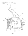
- the spinning reel 100 is a reel capable of delivering fishing line forward. As illustrated in FIG. 1 , the spinning reel 100 is comprised of a handle 1, a reel body 2 that rotatably supports the handle 1, a rotor 3, and a spool 4.
- the rotor 3 is rotatably supported at the front portion of the reel body 2.
- the spool 4 is for winding fishing line on the peripheral surface and is disposed at the front portion of the rotor 3 to freely move in the lengthwise direction.
- the handle 1 can be mounted at the left or the right side of the reel body 2.
- the reel body 2 is comprised of a housing 21, a cover member 22, and a guard member 23.
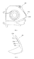
- the housing 21 is formed, for example, from a light alloy such as a magnesium alloy, an aluminum alloy, or the like. As illustrated in FIG. 2 , the housing 21 has a housing space 21a wherein the first side face (the front side in FIG. 2 ) is opened.
- the housing space 21 a is roughly square-shaped. This housing space 21 a houses the rotor drive mechanism 5 and the oscillating mechanism 6 to be described later.
- the housing 21 includes a sidewall 21 b that demarcates the second side face (the side face that is the back side in FIG. 2 ) of the housing space 21 a and a rear wall 21 c that demarcates the rear face of the housing space 21 a.
- the second side face opposes the first side face.
- the sidewall 21 b has a flat protruding piece (one example for the rear portion of the sidewall) 21d that extends more to the rear than the rear wall 21 c.
- the protruding piece 21 d has a side view that is roughly triangle-shaped, and the apex is located at the rear end thereof.
- the thickness of the protruding piece 21d is preferably not less than 1 mm and not greater than 4 mm. If the thickness of the protruding piece 21 d is greater than 1 mm, the housing 21 can be easily molded according to a die casting process. Also, if the thickness of the protruding piece 21 d is less than 4 mm, the weight can be reduced, and the generation of shrinkage after molding can be suppressed when the housing 21 is molded according to a die casting process.
- the rear face 21e of the rear wall 21 c is substantially flat-shaped.
- the length from this rear face 21e to the rear end of the protruding piece 21 d, namely, the length L in the lengthwise direction of the protruding piece 21d, is preferably greater than 2 mm and less than 10 mm.
- the housing 21 includes a T-shaped fishing pole mounting portion 21f that extends in the lengthwise direction, a cylindrical portion 21g for housing an anti-reversal mechanism 50, or the like.
- the housing 21 has a front wall 21 h that demarcates the front face of the housing space 21 a.
- a first communicating hole 21 i that links the housing space 21 a to the outside is formed on the front wall 21 h.
- a second communicating hole 21j that links the housing space 21 a to the outside is formed on the rear wall 21 c of the housing 21 at a position that opposes the first communicating hole 21 i.
- the first communicating hole 21 i is formed from a round hole that has a minor diameter that allows a bolt 24 ( FIG. 6 ) to pass through.
- the first communicating hole 21 i is formed on the first protruding portion 21 k that protrudes from the front wall 21 h of the housing 21 towards the second communicating hole 21j.
- the first communicating hole 21 i is closed with a plug member 25 ( FIG. 6 ) after the guard member 23 has been mounted with a bolt 24.
- the second communicating hole 21j is formed on the second protruding portion 21l that protrudes from the rear wall 21 c of the housing 21 towards the first communication hole 21i.
- the second communicating hole 21j is a stepped hole formed to include a large diameter portion and a small diameter portion, and a boss portion 23a of the guard member 23 to be described later is inserted into the large diameter portion. Also, the shaft portion 24b of the bolt 24 can be inserted into the small diameter portion of the second communicating hole 21j.
- the cover member 22 is detachably mounted to the housing 21 to close the opening of the housing space 21 a.
- the cover member 22 is made, for example, from a light alloy such as a magnesium alloy, an aluminum alloy, or the like.
- the cover member 22 is fixed to the housing 21, for example, at two spots on the front side hidden by the rotor 3 with two bolts that are not illustrated in the drawing.
- the two bolts on the front side are screwed to the two threaded holes 21 m formed in the front portion of the housing 21.
- the cover member 22 is fixed to the housing 21 at one spot on the rear side that is separated from the rotor 3 with a bolt not illustrated in the drawing.
- the bolt on the rear side is screwed to the threaded hole 21 n formed to the rear portion of the housing 21.
- the bolt on the rear side is covered according to the guard member 23. Therefore, the bolt that fixes the cover member 22 is not exposed to the outside of the reel body 2.
- the cover member 22 has a rear portion 22a that is positioned more to the rear than the rear wall 21 c of the housing 21 when in a state of having been mounted to the housing 21.
- This rear portion 22a is roughly triangle-shaped, that is, roughly the same shape as the protruding piece 21 d of the housing 21 when viewed from the side.
- the cover member 22 demarcates the second side face of the housing space 21 a when in a state of having been mounted to the housing 21.
- the guard member 23 is the member that is mounted to the housing 21 and the cover member 22 from the rear.
- the guard member 23 forms the rear portion of the reel body 2 and has a boomerang shape when viewed from the side. Furthermore, the external shape as viewed from the right side and the external shape as viewed from the left side are approximately the same in the side view of the guard member 23.
- the guard member 23 is mounted to the housing 21 and the cover member 22 via a seal not illustrated in the drawing.
- the boss portion 23a of the guard member 23 is formed into a rod shape such that a bolt 24 can be screwed in at the center.
- the boss portion 23a protrudes forward and can be inserted into the second communicating hole 21j.
- the boss portion 23a can be inserted into the large diameter portion of the second communicating hole 21j as described above.
- a threaded hole whereto the bolt 24 is screwed in is formed at the center of the boss portion 23a.
- the threaded hole of this boss portion 23a extends to the middle position in the axial direction of the boss portion 23a.
- the boss portion 23a has a length that allows for a difference in level and formation of the space between the first hole portion 21 m and the second hole portion 21 n when the guard member 23 is fixed. Also, the guard member 23 is formed with a stepped through hole (omitted from the drawing) at the bottom portion, and the bottom portion is screwed to the housing 21 by using this through hole.
- the front face 23b of the guard member 23 has a shape that follows along the rear face 21 p of the protruding piece 21 d and the rear face 22b of the rear portion 22a of the cover member 22.
- the guard member 23 has many protruding portions 23c that protrude forward. Each protruding portion 23c is disposed at a position capable of making contact with the inside face of the protruding piece 21 d and the inside face of the cover member 22, namely, at a position that approaches or makes contact with the inside face of the protruding piece or the cover member.
- a space is formed according to the housing 21, the cover member 22, and the guard member 23 when the guard member 23 is mounted at the rear of the housing 21 and the cover member 22.
- the bolt 24 has a head portion 24a and a shaft portion 24b wherein the diameter is smaller than that of the head portion 24a and a male thread is formed at its periphery.
- the bolt 24 is screwed to the threaded hole formed to the boss portion 23a.
- the bolt 24 is mounted to a cylindrical member 26 before assembling the spinning reel.
- the extreme end of a fastening tool such as a driver or the like, is inserted into the cylindrical member 26 via the first communicating hole 21 i and is screwed to the boss portion 23a of the guard member 23 by turning the bolt 24 with the fastening tool. Accordingly, the guard member 23 and the cylindrical member 26 are fixed to the housing 21.
- the plug member 25 is made from an elastic body, such as synthetic rubber or the like, and seals the space between the cylindrical member 26 and the first communicating hole 21 i by being fitted to the respective inner circumferential surface of the first communicating hole 21i and the cylindrical portion 26a of the cylindrical member 26. It is possible with this plug member 25 to prevent liquid from infiltrating into the housing space 21 a from the inside of the cylindrical member 26, as well as to prevent the infiltration of liquid into the housing space 21a from the first communicating hole 21 i.
- the cylindrical member 26 is a member made, for example, from a synthetic resin, such as a polyamide resin, polyacetal, or the like.
- the cylindrical member 26 is disposed between the first communicating hole 21 i and the second communicating hole 21j in the housing space 21 a of the housing 21.
- the cylindrical member 26 is comprised of a cylindrical portion 26a whereto the head portion 24a of the bolt 24 can be inserted, a bottom portion 26b, and a seal mounting portion 26c.
- the cylindrical potion 26a has a hole that is substantially the same diameter as that of the first communicating hole 21i.
- the bottom portion 26b is disposed to oppose the front face of the second protruding portion 21l.
- the bottom portion 26b has a through hole wherein the shaft portion 24b of the bolt 24 can be inserted and has substantially the same diameter as the small diameter portion of the second communicating hole 21j.
- the bottom portion 26b can fasten the head portion 24a of the bolt 24.
- the seal mounting portion 26c protrudes in a cylindrical shape from the bottom portion 26b towards the second protruding portion 21l. The extreme end portion of the seal mounting portion 26c is disposed by making contact with the second protruding portion 21l.
- the second seal member 27 is an O-ring that is mounted to the seal mounting portion 26c and seals the space between the cylindrical member 26 and the second communicating hole 21j.
- the second seal member 27 is sandwiched between the bottom portion 26b and the second protruding portion 21l and is slightly compressed in a state wherein the rear side of the seal mounting portion 26c makes contact with the front face of the second protruding portion 21l. Accordingly, the second seal member 27 seals the space between the bottom portion 26b and the second protruding portion 21l. As a result, infiltration of liquid into the housing space 21 a from the cylindrical member 26 can be prevented even if liquid infiltrates into the second communicating hole 21j.
- the bolt 24 for attaching the guard member 23 is covered with a plug member 25. Accordingly, it is possible to obtain a clean outer appearance wherein the bolt 24 is not exposed to the outside. Also, the space between the first communicating hole 21 i and the cylindrical member 26 is sealed with the plug member 25, and the space between the second communicating hole 21j and the cylindrical member is sealed with the second seal member 27. Accordingly, it is possible to suppress the infiltration of liquid into the housing space 21 a and to easily fasten the guard member 23 without exposing the bolt 24 to the outside. Also, even the threaded member for fixing the cover member 22 to the housing 21 is hidden by the rotor 3, and the guard member 23 and fastening bolts thereof are not exposed to the outside.
- the rotor drive mechanism 5 is comprised of a drive shaft 5a, a drive gear 5b in the form of a face gear that is integrally installed to the drive shaft 5a or as a separate member, and a pinion gear 5c that interlocks with the drive gear 5b.
- the pinion gear 5c is formed into a cylindrical shape, and the front portion of the pinion gear 5c passes through the center portion of the rotor 3 and is fixed to the rotor 3 with a nut 13. Also, the middle portion and the rear end portion in the axial direction of the pinion gear 5c are rotatably supported by the reel body 2 via the bearings 14a and 14b, respectively.
- the oscillating mechanism 6 is a mechanism for moving the spool shaft 15 that is coupled to the center portion of the spool 4 via a drag mechanism 60 in the lengthwise direction, thereby moving the spool 4 in the same direction.
- the oscillating mechanism 6 is comprised of a traverse camshaft 6a that is disposed below the spool shaft 15 to be parallel to the spool shaft, a slider 6b that moves in the lengthwise direction along the traverse camshaft 6a, and a middle gear 6c that is fixed to the extreme end of the traverse camshaft 6a.
- the rear end portion of the spool shaft 15 is rotatably fixed to the slider 6b.
- the middle gear 6c interlocks with the pinion gear 5c.
- the rotor 3 can rotate around the first axis X in the lengthwise direction in relation to the reel body 2.
- the rotor 3 is rotatably and integrally coupled to the pinion gear 5c.
- the rotor 3 is comprised of a roughly cylinder-shaped rotor body 3a that is coupled to the pinion gear 5c and a first rotor arm 3b and a second rotor arm 3c that extend from the both sides of the rotor body 3a.
- the rotor 3 also includes a bail arm 3d that is pivotally coupled to the first rotor arm 3b and the second rotor arm 3c.
- the bail arm 3d is provided to wind fishing line onto a spool 4.
- the rotor 3 can be switched between the prohibit reversal state and the allow reversal state with an anti-reversal mechanism 50 provided with a roller-type one-way clutch 51. This switching operation is carried out with a switch lever (omitted from the drawing) that is disposed below the reel body 2.
- the spool 4 is disposed between the first rotor arm 3b and the second rotor arm 3c of the rotor 3.
- the spool 4 is mounted to the extreme end of the spool shaft 15 via a drag mechanism 60.
- the spool 4 is comprised of fishing line winding drum portion 4a whereto fishing line is wound on the periphery, a cylindrical skirt portion 4b that is integrally formed to the fishing line winding drum portion 4a at the rear of the fishing line winding drum portion 4a, and a flange portion 4c with a large diameter provided to the front end of the fishing line winding drum portion 4a.
- the drag mechanism 60 is the mechanism for braking rotation of the spool 4 and is comprised of a drag adjustment knob 61 that is screwed to the extreme end of the spool shaft 15 and a brake portion 62 that is pressurized by the drag adjustment knob 61 and applies a braking force to the spool 4.
- an escape portion 23d on the inside of the guard member 23 according to a T-slot milling process or the like. According to this escape portion 23d, it is possible to prevent the protruding portion 21 q that protrudes rearward from the rear face 21 c of the rear wall 21 c from interfering with the inside face of the guard member 23. As a result, the bottom face of the guard member 23 can be shifted in the upward direction. Accordingly, the bottom face of the guard member 23 does not protrude downward in relation to the housing 21 even if, for example, sack holes for the bolts to fasten the guard member 23 and the housing 21 are formed on the bottom face of the guard member 23.
- the protruding piece 21d was described to be one portion (the rear portion) of the sidewall 21 b.
- the protruding piece 21 d can be expressed as follows as a separate member from the sidewall 21 b. Namely, the protruding piece 21d is formed along one section of one of the side edges (the right-side edge in FIG. 3 ) of the rear wall 21 c, and the outside face of the protruding piece 21d is formed smoothly and continuously to the outside face of the sidewall 21 b.
- the guard member 23 need not have the protruding portion 23c. Also, the rear portion 22a of the cover member 22 and the protruding piece 21d can have varying shapes in the side view.
Landscapes
- Life Sciences & Earth Sciences (AREA)
- Environmental Sciences (AREA)
- Animal Husbandry (AREA)
- Biodiversity & Conservation Biology (AREA)
Abstract
Description
- This application claims priority to Japanese Patent Application No.
2012-277876 filed on 20 December, 2012 2012-277876 - The present invention relates to a reel body of a spinning reel that delivers fishing line forward and a spinning reel that uses this reel body.
- A reel body of a spinning reel is comprised of a housing that has a housing space for housing an oscillating mechanism, a rotor drive mechanism, or the like, a cover member mounted to the housing so as to close the opening formed to the housing, and a guard member that covers the rear portion of the cover member (refer to Patent Document 1). For design and to prevent the fishing line from becoming tangled, this housing has a shape wherein the side view becomes narrower toward the rear portion.
- Such a real body is disclosed in Japanese Laid Open Patent Publication No.
2004-129571 - The housing space in the housing is preferably made small from the standpoint of preventing infiltration of water into the housing space. For example, the housing space can be made small by shifting the rear face of the housing space forward. However, greatly changing the external shape in the side view of the housing rear portion is not favorable due to the reason described above. When the rear face of the housing space is shift forward without greatly changing the external shape in the side view of the housing rear portion to satisfy this need, extra thickness is necessary by the amount the housing space was decreased according to the shift in the rear portion of the housing space, and this creates a problem of increasing the weight.
- The object of the present invention is to reduce the weight of the reel body without forfeiting the design and functionality of the rear portion of the reel body.
- The reel body according to the first aspect of the present invention is a reel body of a spinning reel that is capable of delivering fishing line forward and that comprises a housing, a cover member, and a guard member. The housing has a housing space wherein the first side face is opened, a sidewall that demarcates the second side face of the housing space that opposes the first side face, and a rear wall that demarcates the rear face of the housing space. The rear portion of the sidewall extends more towards the rear than the rear wall. The cover member is mounted to the housing to cover the opening of the housing space. The guard member is mounted from the rear of the housing and the cover member to form a space between the rear portion of the sidewall and the rear wall.
- According to this configuration, the rear portion of the sidewall extends more towards the rear than the rear wall, and the rear portion of the housing can have approximately the same external appearance as that of the conventional art. Also, the rear wall is positioned more towards the front than the rear end of the housing. Therefore, the guard member can be mounted to the housing in a state of having formed a space between the rear portion of the sidewall and the rear wall of the housing. Accordingly, decreasing the weight of the reel body is made possible without forfeiting the design and functionality of the rear portion of the reel body.
- Preferably, the rear portion of the cover member extends more towards the rear than the rear wall. According to this configuration, a space is formed at the rear portion of the reel body from the rear portion of the sidewall and the rear wall of the housing, the rear portion of the cover member, and the guard member. Accordingly, decreasing the weight of the reel body is made possible without forfeiting the design when viewed from the side mounted with the cover member.
- Preferably, the guard member has at least one protruding portion that protrudes forward. Also, the protruding portion is disposed at a position capable of making contact with the inside face of the rear portion of the housing. According to this configuration, even in a case when a load is applied to the guard member from the side, a sideways movement of the guard member is restricted by the protruding portion making contact with the inside face of the rear portion of the housing. Therefore, a sideways displacement in the position of the guard member can be prevented. Furthermore, the protruding portion can make contact with the inside face of the rear portion of the housing or be disposed to be adjacent to the inside face of the rear portion of the housing in advance.
- Preferably, the guard member has many protruding portions that protrude forward. Each protruding portion is disposed at a position capable of making contact with the inside face of the rear portion of the housing or with the inside face of the rear portion of the cover member. According to this configuration, even in a case when a load is applied to the guard member from the side, a sideways movement of the guard member is restricted by the protruding portion making contact with the inside face of the rear portion of the housing or with the inside face of the rear portion of the cover member. Therefore, a sideways displacement in the position of the guard member can be prevented. Furthermore, the protruding portion can make contact with the inside face of the rear portion of the housing or with the inside face of the rear portion of the cover member or be disposed to be adjacent to the inside face of the rear portion of the housing or the inside face of the rear portion of the cover member in advance.
- Preferably, the rear portion of the cover member has the same shape as the rear portion of the sidewall when viewed from the side. According to this configuration, the reel body is bilaterally symmetrical. Therefore, the design is enhanced, the shape of the guard member mounted to the rear portion of the housing can have as close to a bilaterally symmetrical shape as possible, and extreme unbalance can be avoided.
- Preferably, the front face of the guard member has a shape that follows along the rear face of the side wall and the rear face of the cover member when viewed from the side. According to this configuration, the adhesion is enhanced when the guard member is mounted to the housing and the cover member, and the strength of the guard member is enhanced at the time of mounting.
- According to another aspect a spinning reel is provided having the above reel body and further comprising a handle that is rotatably mounted to the reel body, a spool whereon fishing line is wound, and a rotor for winding fishing line on the spool. Therefore, the weight can be reduced without forfeiting the design and functionality.
- According to the present invention, the weight of the housing can be reduced without forfeiting the design and functionality of the rear portion of the reel body.
-
- [
FIG. 1 ] is a side view of a spinning reel. - [
FIG. 2 ] is a side view of a housing. - [
FIG. 3 ] is a back view of a housing. - [
FIG. 4 ] is a side view of a cover member. - [
FIG. 5 ] is a side view of a guard member. - [
FIG. 6 ] is a cross-sectional side view of a spinning reel. - [
FIG. 7 ] is a cross-sectional side view of a cylindrical member in a state where a bolt is mounted. - [
FIG. 8 ] is a back view of a housing related to the first modification. - Below, an embodiment of the spinning reel related to the present invention will be described by referring to the drawings. In the description below, "front" refers to the left in
FIGS. 1 to 6 (excludingFIG. 3 ); "rear" refers to the right inFIGS. 1 to 6 (excludingFIG. 3 ); "top" refers to the top inFIGS. 1 to 6 (excludingFIG. 3 ); and "bottom" refers to the bottom inFIGS. 1 to 6 (excludingFIG. 3 ). - The
spinning reel 100 is a reel capable of delivering fishing line forward. As illustrated inFIG. 1 , thespinning reel 100 is comprised of ahandle 1, areel body 2 that rotatably supports thehandle 1, arotor 3, and aspool 4. Therotor 3 is rotatably supported at the front portion of thereel body 2. Thespool 4 is for winding fishing line on the peripheral surface and is disposed at the front portion of therotor 3 to freely move in the lengthwise direction. Thehandle 1 can be mounted at the left or the right side of thereel body 2. - The
reel body 2 is comprised of ahousing 21, acover member 22, and aguard member 23. - The
housing 21 is formed, for example, from a light alloy such as a magnesium alloy, an aluminum alloy, or the like. As illustrated inFIG. 2 , thehousing 21 has ahousing space 21a wherein the first side face (the front side inFIG. 2 ) is opened. Thehousing space 21 a is roughly square-shaped. Thishousing space 21 a houses therotor drive mechanism 5 and theoscillating mechanism 6 to be described later. - As illustrated in
FIGS. 2 and3 , thehousing 21 includes asidewall 21 b that demarcates the second side face (the side face that is the back side inFIG. 2 ) of thehousing space 21 a and arear wall 21 c that demarcates the rear face of thehousing space 21 a. The second side face opposes the first side face. Thesidewall 21 b has a flat protruding piece (one example for the rear portion of the sidewall) 21d that extends more to the rear than therear wall 21 c. The protrudingpiece 21 d has a side view that is roughly triangle-shaped, and the apex is located at the rear end thereof. The thickness of the protrudingpiece 21d is preferably not less than 1 mm and not greater than 4 mm. If the thickness of the protrudingpiece 21 d is greater than 1 mm, thehousing 21 can be easily molded according to a die casting process. Also, if the thickness of the protrudingpiece 21 d is less than 4 mm, the weight can be reduced, and the generation of shrinkage after molding can be suppressed when thehousing 21 is molded according to a die casting process. - The
rear face 21e of therear wall 21 c is substantially flat-shaped. The length from thisrear face 21e to the rear end of the protrudingpiece 21 d, namely, the length L in the lengthwise direction of the protrudingpiece 21d, is preferably greater than 2 mm and less than 10 mm. Also, thehousing 21 includes a T-shaped fishingpole mounting portion 21f that extends in the lengthwise direction, acylindrical portion 21g for housing ananti-reversal mechanism 50, or the like. - As illustrated in
FIG. 2 , thehousing 21 has afront wall 21 h that demarcates the front face of thehousing space 21 a. A first communicatinghole 21 i that links thehousing space 21 a to the outside is formed on thefront wall 21 h. Also, a second communicatinghole 21j that links thehousing space 21 a to the outside is formed on therear wall 21 c of thehousing 21 at a position that opposes the first communicatinghole 21 i. - The first communicating
hole 21 i is formed from a round hole that has a minor diameter that allows a bolt 24 (FIG. 6 ) to pass through. The first communicatinghole 21 i is formed on the first protrudingportion 21 k that protrudes from thefront wall 21 h of thehousing 21 towards the second communicatinghole 21j. The first communicatinghole 21 i is closed with a plug member 25 (FIG. 6 ) after theguard member 23 has been mounted with abolt 24. - The second communicating
hole 21j is formed on the second protruding portion 21l that protrudes from therear wall 21 c of thehousing 21 towards thefirst communication hole 21i. The second communicatinghole 21j is a stepped hole formed to include a large diameter portion and a small diameter portion, and aboss portion 23a of theguard member 23 to be described later is inserted into the large diameter portion. Also, theshaft portion 24b of thebolt 24 can be inserted into the small diameter portion of the second communicatinghole 21j. - The
cover member 22 is detachably mounted to thehousing 21 to close the opening of thehousing space 21 a. Thecover member 22 is made, for example, from a light alloy such as a magnesium alloy, an aluminum alloy, or the like. As illustrated inFIG. 4 , thecover member 22 is fixed to thehousing 21, for example, at two spots on the front side hidden by therotor 3 with two bolts that are not illustrated in the drawing. The two bolts on the front side are screwed to the two threadedholes 21 m formed in the front portion of thehousing 21. Also, thecover member 22 is fixed to thehousing 21 at one spot on the rear side that is separated from therotor 3 with a bolt not illustrated in the drawing. The bolt on the rear side is screwed to the threadedhole 21 n formed to the rear portion of thehousing 21. The bolt on the rear side is covered according to theguard member 23. Therefore, the bolt that fixes thecover member 22 is not exposed to the outside of thereel body 2. - The
cover member 22 has arear portion 22a that is positioned more to the rear than therear wall 21 c of thehousing 21 when in a state of having been mounted to thehousing 21. Thisrear portion 22a is roughly triangle-shaped, that is, roughly the same shape as the protrudingpiece 21 d of thehousing 21 when viewed from the side. Thecover member 22 demarcates the second side face of thehousing space 21 a when in a state of having been mounted to thehousing 21. - The
guard member 23 is the member that is mounted to thehousing 21 and thecover member 22 from the rear. Theguard member 23 forms the rear portion of thereel body 2 and has a boomerang shape when viewed from the side. Furthermore, the external shape as viewed from the right side and the external shape as viewed from the left side are approximately the same in the side view of theguard member 23. - For appearance, the
guard member 23 is mounted to thehousing 21 and thecover member 22 via a seal not illustrated in the drawing. Theboss portion 23a of theguard member 23 is formed into a rod shape such that abolt 24 can be screwed in at the center. Theboss portion 23a protrudes forward and can be inserted into the second communicatinghole 21j. Specifically, theboss portion 23a can be inserted into the large diameter portion of the second communicatinghole 21j as described above. A threaded hole whereto thebolt 24 is screwed in is formed at the center of theboss portion 23a. The threaded hole of thisboss portion 23a extends to the middle position in the axial direction of theboss portion 23a. Theboss portion 23a has a length that allows for a difference in level and formation of the space between thefirst hole portion 21 m and thesecond hole portion 21 n when theguard member 23 is fixed. Also, theguard member 23 is formed with a stepped through hole (omitted from the drawing) at the bottom portion, and the bottom portion is screwed to thehousing 21 by using this through hole. - The
front face 23b of theguard member 23 has a shape that follows along therear face 21 p of the protrudingpiece 21 d and therear face 22b of therear portion 22a of thecover member 22. Also, theguard member 23 has many protrudingportions 23c that protrude forward. Each protrudingportion 23c is disposed at a position capable of making contact with the inside face of the protrudingpiece 21 d and the inside face of thecover member 22, namely, at a position that approaches or makes contact with the inside face of the protruding piece or the cover member. A space is formed according to thehousing 21, thecover member 22, and theguard member 23 when theguard member 23 is mounted at the rear of thehousing 21 and thecover member 22. - As illustrated in
FIG. 7 , thebolt 24 has ahead portion 24a and ashaft portion 24b wherein the diameter is smaller than that of thehead portion 24a and a male thread is formed at its periphery. Thebolt 24 is screwed to the threaded hole formed to theboss portion 23a. Thebolt 24 is mounted to acylindrical member 26 before assembling the spinning reel. At the time of the assembly, the extreme end of a fastening tool, such as a driver or the like, is inserted into thecylindrical member 26 via the first communicatinghole 21 i and is screwed to theboss portion 23a of theguard member 23 by turning thebolt 24 with the fastening tool. Accordingly, theguard member 23 and thecylindrical member 26 are fixed to thehousing 21. - The
plug member 25 is made from an elastic body, such as synthetic rubber or the like, and seals the space between thecylindrical member 26 and the first communicatinghole 21 i by being fitted to the respective inner circumferential surface of the first communicatinghole 21i and thecylindrical portion 26a of thecylindrical member 26. It is possible with thisplug member 25 to prevent liquid from infiltrating into thehousing space 21 a from the inside of thecylindrical member 26, as well as to prevent the infiltration of liquid into thehousing space 21a from the first communicatinghole 21 i. - The
cylindrical member 26 is a member made, for example, from a synthetic resin, such as a polyamide resin, polyacetal, or the like. Thecylindrical member 26 is disposed between the first communicatinghole 21 i and the second communicatinghole 21j in thehousing space 21 a of thehousing 21. As illustrated inFIG. 7 , thecylindrical member 26 is comprised of acylindrical portion 26a whereto thehead portion 24a of thebolt 24 can be inserted, abottom portion 26b, and aseal mounting portion 26c. Thecylindrical potion 26a has a hole that is substantially the same diameter as that of the first communicatinghole 21i. Thebottom portion 26b is disposed to oppose the front face of the second protruding portion 21l. Thebottom portion 26b has a through hole wherein theshaft portion 24b of thebolt 24 can be inserted and has substantially the same diameter as the small diameter portion of the second communicatinghole 21j. Thebottom portion 26b can fasten thehead portion 24a of thebolt 24. Theseal mounting portion 26c protrudes in a cylindrical shape from thebottom portion 26b towards the second protruding portion 21l. The extreme end portion of theseal mounting portion 26c is disposed by making contact with the second protruding portion 21l. - The
second seal member 27 is an O-ring that is mounted to theseal mounting portion 26c and seals the space between thecylindrical member 26 and the second communicatinghole 21j. Thesecond seal member 27 is sandwiched between thebottom portion 26b and the second protruding portion 21l and is slightly compressed in a state wherein the rear side of theseal mounting portion 26c makes contact with the front face of the second protruding portion 21l. Accordingly, thesecond seal member 27 seals the space between thebottom portion 26b and the second protruding portion 21l. As a result, infiltration of liquid into thehousing space 21 a from thecylindrical member 26 can be prevented even if liquid infiltrates into the second communicatinghole 21j. - In this
reel body 2, thebolt 24 for attaching theguard member 23 is covered with aplug member 25. Accordingly, it is possible to obtain a clean outer appearance wherein thebolt 24 is not exposed to the outside. Also, the space between the first communicatinghole 21 i and thecylindrical member 26 is sealed with theplug member 25, and the space between the second communicatinghole 21j and the cylindrical member is sealed with thesecond seal member 27. Accordingly, it is possible to suppress the infiltration of liquid into thehousing space 21 a and to easily fasten theguard member 23 without exposing thebolt 24 to the outside. Also, even the threaded member for fixing thecover member 22 to thehousing 21 is hidden by therotor 3, and theguard member 23 and fastening bolts thereof are not exposed to the outside. - As illustrated in
FIG. 6 , therotor drive mechanism 5 is comprised of adrive shaft 5a, adrive gear 5b in the form of a face gear that is integrally installed to thedrive shaft 5a or as a separate member, and a pinion gear 5c that interlocks with thedrive gear 5b. - The pinion gear 5c is formed into a cylindrical shape, and the front portion of the pinion gear 5c passes through the center portion of the
rotor 3 and is fixed to therotor 3 with anut 13. Also, the middle portion and the rear end portion in the axial direction of the pinion gear 5c are rotatably supported by thereel body 2 via thebearings - The
oscillating mechanism 6 is a mechanism for moving thespool shaft 15 that is coupled to the center portion of thespool 4 via adrag mechanism 60 in the lengthwise direction, thereby moving thespool 4 in the same direction. Theoscillating mechanism 6 is comprised of atraverse camshaft 6a that is disposed below thespool shaft 15 to be parallel to the spool shaft, aslider 6b that moves in the lengthwise direction along thetraverse camshaft 6a, and amiddle gear 6c that is fixed to the extreme end of thetraverse camshaft 6a. The rear end portion of thespool shaft 15 is rotatably fixed to theslider 6b. Themiddle gear 6c interlocks with the pinion gear 5c. - The
rotor 3 can rotate around the first axis X in the lengthwise direction in relation to thereel body 2. Therotor 3 is rotatably and integrally coupled to the pinion gear 5c. Therotor 3 is comprised of a roughly cylinder-shapedrotor body 3a that is coupled to the pinion gear 5c and afirst rotor arm 3b and asecond rotor arm 3c that extend from the both sides of therotor body 3a. Therotor 3 also includes abail arm 3d that is pivotally coupled to thefirst rotor arm 3b and thesecond rotor arm 3c. Thebail arm 3d is provided to wind fishing line onto aspool 4. - The
rotor 3 can be switched between the prohibit reversal state and the allow reversal state with ananti-reversal mechanism 50 provided with a roller-type one-way clutch 51. This switching operation is carried out with a switch lever (omitted from the drawing) that is disposed below thereel body 2. - The
spool 4 is disposed between thefirst rotor arm 3b and thesecond rotor arm 3c of therotor 3. Thespool 4 is mounted to the extreme end of thespool shaft 15 via adrag mechanism 60. Thespool 4 is comprised of fishing line winding drum portion 4a whereto fishing line is wound on the periphery, acylindrical skirt portion 4b that is integrally formed to the fishing line winding drum portion 4a at the rear of the fishing line winding drum portion 4a, and aflange portion 4c with a large diameter provided to the front end of the fishing line winding drum portion 4a. - The
drag mechanism 60 is the mechanism for braking rotation of thespool 4 and is comprised of adrag adjustment knob 61 that is screwed to the extreme end of thespool shaft 15 and abrake portion 62 that is pressurized by thedrag adjustment knob 61 and applies a braking force to thespool 4. - The embodiment described above can be expressed as follows.
- (1) The
reel body 2 is the reel body of a spinning reel capable of delivering fishing line forward and is comprised of ahousing 21, acover member 22, and aguard member 23. Thehousing 21 has ahousing space 21 a, wherein the first side face is opened, asidewall 21 b that demarcates the second side face of thehousing space 21 a and opposes the first side face, and arear wall 21 c that demarcates the rear face of thehousing space 21 a. The protrudingpiece 21 d, which is the rear portion of thesidewall 21 b, extends more towards the rear than therear wall 21 c. Thecover member 22 is mounted to thehousing 21 to cover the opening of thehousing space 21 a. Theguard member 23 is mounted from the rear of thehousing 21 and thecover member 22 to form a space between the protrudingpiece 21d and therear wall 21 c.
According to this configuration, the protrudingpiece 21d, which is the rear portion of thesidewall 21 b, extends more towards the rear than therear wall 21 c. Therefore, the rear portion of thehousing 21 can have about the same external appearance as that of the conventional art. Also, therear wall 21 c is positioned more towards the front than the rear end of thehousing 21. Therefore, theguard member 23 can be mounted to thehousing 21 forming a space between the protrudingpiece 21 d and therear wall 21 c. Accordingly, decreasing the weight of thereel body 2 is made possible without forfeiting the design and functionality of the rear portion of thereel body 2. - (2) The
rear portion 22a of thecover member 22 extends more towards the rear than therear wall 21 c. According to this configuration, a space is formed at the rear portion of thereel body 2 from the protrudingportion 21d and therear wall 21 c of thehousing 21, therear portion 22a of thecover member 22, and theguard member 23. Accordingly, decreasing the weight of thereel body 2 is made possible without forfeiting the design and the functionality when viewed from the side mounted with thecover member 22. - (3) The
rear portion 22a of thecover member 22 has the same shape as the protrudingpiece 21d when viewed from the side. According to this configuration, thereel body 2 is bilaterally symmetrical. Therefore, the design and the functionality are enhanced, and balance is achieved in the mounting strength. - (4) The
guard member 23 has a shape wherein thefront face 23b follows along therear face 21 p of the sidewall and therear face 22b of thecover member 22 when viewed from the side. According to this configuration, the adhesion for mounting theguard member 23 to thehousing 21 and thecover member 22 is enhanced, and the mounting strength is enhanced. - (5) The
guard member 23 has at least one protrudingportion 23c that protrudes forward. Also, the protrudingportion 23c is disposed at a position capable of making contact with the inside face of the protrudingpiece 21d. According to this configuration, even in a case where a load is applied to theguard member 23 from the side, a sideways movement of theguard member 23 is restricted by the protrudingportion 23c making contact with the inside face of the protrudingpiece 21d, and a sideways displacement in the position of theguard member 23 can be prevented. - (6) The
guard member 23 has multiple protrudingportions 23c. At least one protrudingportion 23c is disposed at a position capable of making contact with the inside face of therear portion 22a of thecover member 22. According to this configuration, a sideways movement of theguard member 23 is restricted also by the protrudingportion 23c making contact with the inside face of therear portion 22a of thecover member 22. Therefore, a sideways displacement in the position of theguard member 23 can surely be prevented. - (7) The spinning reel is comprised of a
reel body 2, ahandle 1 that is rotatably mounted to thereel body 2, aspool 4 whereon fishing line is wound, and arotor 3 for winding fishing line on thespool 4. According to this configuration, thereel body 2 that was described above is provided. Therefore, the weight can be reduced without forfeiting the design and functionality. - An embodiment of the present invention was described above. However, the present invention is not limited to the embodiment described above, and various changes are possible in a scope of not deviating from the essence of the invention. In particular, the many embodiments and modifications described in the specification can be optionally combined as needed.
- As illustrated in
FIG. 8 , it is possible to form anescape portion 23d on the inside of theguard member 23 according to a T-slot milling process or the like. According to thisescape portion 23d, it is possible to prevent the protruding portion 21 q that protrudes rearward from therear face 21 c of therear wall 21 c from interfering with the inside face of theguard member 23. As a result, the bottom face of theguard member 23 can be shifted in the upward direction. Accordingly, the bottom face of theguard member 23 does not protrude downward in relation to thehousing 21 even if, for example, sack holes for the bolts to fasten theguard member 23 and thehousing 21 are formed on the bottom face of theguard member 23. - In the embodiment described above, the protruding
piece 21d was described to be one portion (the rear portion) of thesidewall 21 b. However, the protrudingpiece 21 d can be expressed as follows as a separate member from thesidewall 21 b. Namely, the protrudingpiece 21d is formed along one section of one of the side edges (the right-side edge inFIG. 3 ) of therear wall 21 c, and the outside face of the protrudingpiece 21d is formed smoothly and continuously to the outside face of thesidewall 21 b. - The
guard member 23 need not have the protrudingportion 23c. Also, therear portion 22a of thecover member 22 and the protrudingpiece 21d can have varying shapes in the side view. -
- 1
- Handle
- 2
- Reel body
- 21
- Housing
- 21a
- Housing space
- 21b
- Sidewall
- 21c
- Rear wall
- 21d
- Protruding piece (rear portion of the
sidewall 21 b) - 22
- Cover member
- 22a
- Rear portion of the cover member
- 23
- Guard member
- 23c
- Protruding portion
- 3
- Rotor
- 4
- Spool
Claims (7)
- A reel body of a spinning reel capable of delivering fishing line forward, the reel body comprising
a housing, which includes a housing space wherein the first side face is opened, a sidewall that demarcates the second side face of the housing space and opposes the first side face, and a rear wall that demarcates the rear face of the housing space, and the rear portion of the sidewall extends more towards the rear than the rear wall,
a cover member, which is mounted to the housing to cover the opening of the housing space, and
a guard member, which is mounted from the rear of the housing and the cover member to form a space between the rear portion of the sidewall and the rear wall. - The reel body according to claim 1, wherein
the guard member has at least one protruding portion that protrudes forward and
the protruding portion is disposed at a position capable of making contact with the inside face of the rear portion of the housing. - The reel body according to claim 1 or 2, wherein
the rear portion of the cover member extends more towards the rear than the rear wall. - The reel body according to claim 3, wherein
the guard member has many protruding portions that protrude forward, and
each protruding portion is disposed at a position capable of making contact with the inside face of the rear portion of the housing or with the inside face of the rear portion of the cover member. - The reel body according to claim 3 or 4, wherein
the rear portion of the cover member has the same shape as the rear portion of the sidewall when viewed from the side. - The reel body according to any one of the claims 1 to 5, wherein
the front face of the guard member has a shape that follows along the rear face of the sidewall and along the rear face of the cover member when viewed from the side. - A spinning reel comprised of
a reel body described in any one of the claims 1 to 6,
a handle rotatably mounted to the reel body
a spool whereon fishing line is wound, and
a rotor for winding fishing line on a spool.
Applications Claiming Priority (1)
| Application Number | Priority Date | Filing Date | Title |
|---|---|---|---|
| JP2012277876A JP6145606B2 (en) | 2012-12-20 | 2012-12-20 | Reel body and spinning reel |
Publications (2)
| Publication Number | Publication Date |
|---|---|
| EP2745687A1 true EP2745687A1 (en) | 2014-06-25 |
| EP2745687B1 EP2745687B1 (en) | 2018-05-02 |
Family
ID=49765300
Family Applications (1)
| Application Number | Title | Priority Date | Filing Date |
|---|---|---|---|
| EP13195467.9A Active EP2745687B1 (en) | 2012-12-20 | 2013-12-03 | Spinning reel body and spinning reel |
Country Status (7)
| Country | Link |
|---|---|
| US (1) | US8939391B2 (en) |
| EP (1) | EP2745687B1 (en) |
| JP (1) | JP6145606B2 (en) |
| KR (1) | KR102097358B1 (en) |
| CN (1) | CN103875623B (en) |
| MY (1) | MY171013A (en) |
| TW (1) | TWI562725B (en) |
Cited By (1)
| Publication number | Priority date | Publication date | Assignee | Title |
|---|---|---|---|---|
| GB2569439A (en) * | 2017-10-30 | 2019-06-19 | Shimano Kk | Spinning reel |
Families Citing this family (4)
| Publication number | Priority date | Publication date | Assignee | Title |
|---|---|---|---|---|
| JP6986864B2 (en) * | 2017-06-07 | 2021-12-22 | 株式会社シマノ | Electric reel |
| CN110214759B (en) * | 2019-07-22 | 2021-09-10 | 鹤山市仲德精密制造科技有限公司 | Spinning wheel type fishing vessel main body and processing technology thereof |
| JP1705292S (en) * | 2021-05-12 | 2022-01-18 | Fishing reel | |
| JP1719348S (en) * | 2021-12-21 | 2022-07-08 | fishing reel |
Citations (4)
| Publication number | Priority date | Publication date | Assignee | Title |
|---|---|---|---|---|
| JP2004129571A (en) | 2002-10-10 | 2004-04-30 | Daiwa Seiko Inc | Spinning reel for fishing |
| EP1461999A2 (en) * | 2003-02-05 | 2004-09-29 | Shimano Inc. | Reel unit for spinning reel |
| EP1508275A1 (en) * | 2003-08-20 | 2005-02-23 | Shimano Inc. | Spinning reel |
| US20080149750A1 (en) * | 2006-12-21 | 2008-06-26 | Shimano Inc. | Reel unit of spinning reel |
Family Cites Families (17)
| Publication number | Priority date | Publication date | Assignee | Title |
|---|---|---|---|---|
| JPS5838271U (en) * | 1981-09-04 | 1983-03-12 | ダイワ精工株式会社 | spinning reel for fishing |
| JPH01155766U (en) * | 1988-04-20 | 1989-10-26 | ||
| JP2586303Y2 (en) * | 1991-10-15 | 1998-12-02 | 株式会社シマノ | Spinning reel |
| JP2573312Y2 (en) * | 1992-07-27 | 1998-05-28 | 株式会社シマノ | Spinning reel |
| JP2000333565A (en) * | 1999-05-25 | 2000-12-05 | Ryobi Ltd | Fishing reel cover |
| TW440425B (en) * | 1999-07-14 | 2001-06-16 | Shimano Kk | Rotor drive for spinning reel and spinning reel |
| JP3840008B2 (en) * | 1999-10-13 | 2006-11-01 | 株式会社シマノ | Spinning reel body |
| TW495343B (en) * | 2000-11-13 | 2002-07-21 | Shimano Kk | Spinning reel rotor |
| TW534795B (en) * | 2001-05-18 | 2003-06-01 | Shimano Kk | Spinning-reel spool |
| JP3913510B2 (en) * | 2001-10-04 | 2007-05-09 | 株式会社シマノ | Fastening structure for fishing parts |
| US7118059B2 (en) * | 2003-01-29 | 2006-10-10 | Shimano Inc. | Reel unit for spinning reel |
| US7028937B2 (en) * | 2003-02-05 | 2006-04-18 | Shimano Inc. | Reel unit for spinning reel |
| US6932291B2 (en) * | 2003-10-27 | 2005-08-23 | Okuma Fishing Tackle Co., Ltd. | Spinning reel |
| JP2006304675A (en) * | 2005-04-28 | 2006-11-09 | Daiwa Seiko Inc | Fishing spinning reel |
| JP4804330B2 (en) * | 2006-12-21 | 2011-11-02 | 株式会社シマノ | Spinning reel body |
| JP4892416B2 (en) * | 2007-06-15 | 2012-03-07 | 株式会社シマノ | Spinning reel body |
| JP5607315B2 (en) * | 2009-06-02 | 2014-10-15 | シマノコンポネンツ マレーシア エスディーエヌ.ビーエッチディー. | Spinning reel drag knob |
-
2012
- 2012-12-20 JP JP2012277876A patent/JP6145606B2/en active Active
-
2013
- 2013-07-29 KR KR1020130089290A patent/KR102097358B1/en active Active
- 2013-09-05 TW TW102131980A patent/TWI562725B/en active
- 2013-09-19 US US14/031,708 patent/US8939391B2/en active Active
- 2013-10-17 CN CN201310487926.3A patent/CN103875623B/en active Active
- 2013-10-25 MY MYPI2013702035A patent/MY171013A/en unknown
- 2013-12-03 EP EP13195467.9A patent/EP2745687B1/en active Active
Patent Citations (4)
| Publication number | Priority date | Publication date | Assignee | Title |
|---|---|---|---|---|
| JP2004129571A (en) | 2002-10-10 | 2004-04-30 | Daiwa Seiko Inc | Spinning reel for fishing |
| EP1461999A2 (en) * | 2003-02-05 | 2004-09-29 | Shimano Inc. | Reel unit for spinning reel |
| EP1508275A1 (en) * | 2003-08-20 | 2005-02-23 | Shimano Inc. | Spinning reel |
| US20080149750A1 (en) * | 2006-12-21 | 2008-06-26 | Shimano Inc. | Reel unit of spinning reel |
Cited By (1)
| Publication number | Priority date | Publication date | Assignee | Title |
|---|---|---|---|---|
| GB2569439A (en) * | 2017-10-30 | 2019-06-19 | Shimano Kk | Spinning reel |
Also Published As
| Publication number | Publication date |
|---|---|
| TW201424586A (en) | 2014-07-01 |
| JP6145606B2 (en) | 2017-06-14 |
| CN103875623A (en) | 2014-06-25 |
| US20140175207A1 (en) | 2014-06-26 |
| US8939391B2 (en) | 2015-01-27 |
| KR102097358B1 (en) | 2020-04-06 |
| CN103875623B (en) | 2018-08-07 |
| JP2014121277A (en) | 2014-07-03 |
| MY171013A (en) | 2019-09-23 |
| EP2745687B1 (en) | 2018-05-02 |
| KR20140080405A (en) | 2014-06-30 |
| TWI562725B (en) | 2016-12-21 |
Similar Documents
| Publication | Publication Date | Title |
|---|---|---|
| EP2745687B1 (en) | Spinning reel body and spinning reel | |
| KR20080075776A (en) | Handle assembly of spinning reel | |
| JP6046496B2 (en) | Spinning reel | |
| JP5961399B2 (en) | Spinning reel waterproofing material | |
| KR20130111334A (en) | Spinning reel fishing line guide mechanism and spinning reel | |
| JP2013179882A (en) | Spinning reel waterproofing member and spinning reel using the same | |
| US20060071107A1 (en) | Handle knob and handle assembly for a fishing reel | |
| JP2014131491A5 (en) | ||
| US8925847B2 (en) | Spinning reel | |
| KR100983927B1 (en) | Reel body of spinning reel | |
| US7967232B2 (en) | Spinning-reel fishing line guide mechanism | |
| EP2387881B1 (en) | Spinning reel spool | |
| JP5135245B2 (en) | Spinning reel body | |
| JP2002204640A (en) | Spinning reel spool | |
| JP4307937B2 (en) | Spinning reel body | |
| JP4121869B2 (en) | Spinning reel body | |
| JP4141275B2 (en) | Spinning reel body | |
| EP3180977B1 (en) | Spinning reel rotor and spinning reel | |
| JP7384851B2 (en) | spinning reel for fishing | |
| JP3871899B2 (en) | Spinning reel body | |
| JP2005192527A (en) | Reciprocatingly moving device of spinning reel | |
| JP2005229924A (en) | Reel body of spinning reel | |
| JP2017108639A5 (en) | ||
| JP2004229542A (en) | Apparatus for reciprocating spinning reel | |
| JP2011092046A (en) | Spinning-reel fishing line guide mechanism |
Legal Events
| Date | Code | Title | Description |
|---|---|---|---|
| PUAI | Public reference made under article 153(3) epc to a published international application that has entered the european phase |
Free format text: ORIGINAL CODE: 0009012 |
|
| 17P | Request for examination filed |
Effective date: 20131203 |
|
| AK | Designated contracting states |
Kind code of ref document: A1 Designated state(s): AL AT BE BG CH CY CZ DE DK EE ES FI FR GB GR HR HU IE IS IT LI LT LU LV MC MK MT NL NO PL PT RO RS SE SI SK SM TR |
|
| AX | Request for extension of the european patent |
Extension state: BA ME |
|
| R17P | Request for examination filed (corrected) |
Effective date: 20150105 |
|
| RBV | Designated contracting states (corrected) |
Designated state(s): AL AT BE BG CH CY CZ DE DK EE ES FI FR GB GR HR HU IE IS IT LI LT LU LV MC MK MT NL NO PL PT RO RS SE SI SK SM TR |
|
| 17Q | First examination report despatched |
Effective date: 20160609 |
|
| GRAP | Despatch of communication of intention to grant a patent |
Free format text: ORIGINAL CODE: EPIDOSNIGR1 |
|
| INTG | Intention to grant announced |
Effective date: 20171115 |
|
| GRAS | Grant fee paid |
Free format text: ORIGINAL CODE: EPIDOSNIGR3 |
|
| GRAA | (expected) grant |
Free format text: ORIGINAL CODE: 0009210 |
|
| AK | Designated contracting states |
Kind code of ref document: B1 Designated state(s): AL AT BE BG CH CY CZ DE DK EE ES FI FR GB GR HR HU IE IS IT LI LT LU LV MC MK MT NL NO PL PT RO RS SE SI SK SM TR |
|
| REG | Reference to a national code |
Ref country code: GB Ref legal event code: FG4D |
|
| REG | Reference to a national code |
Ref country code: CH Ref legal event code: EP Ref country code: AT Ref legal event code: REF Ref document number: 994241 Country of ref document: AT Kind code of ref document: T Effective date: 20180515 |
|
| REG | Reference to a national code |
Ref country code: DE Ref legal event code: R096 Ref document number: 602013036814 Country of ref document: DE Ref country code: IE Ref legal event code: FG4D |
|
| REG | Reference to a national code |
Ref country code: NL Ref legal event code: MP Effective date: 20180502 |
|
| REG | Reference to a national code |
Ref country code: LT Ref legal event code: MG4D |
|
| PG25 | Lapsed in a contracting state [announced via postgrant information from national office to epo] |
Ref country code: ES Free format text: LAPSE BECAUSE OF FAILURE TO SUBMIT A TRANSLATION OF THE DESCRIPTION OR TO PAY THE FEE WITHIN THE PRESCRIBED TIME-LIMIT Effective date: 20180502 Ref country code: LT Free format text: LAPSE BECAUSE OF FAILURE TO SUBMIT A TRANSLATION OF THE DESCRIPTION OR TO PAY THE FEE WITHIN THE PRESCRIBED TIME-LIMIT Effective date: 20180502 Ref country code: FI Free format text: LAPSE BECAUSE OF FAILURE TO SUBMIT A TRANSLATION OF THE DESCRIPTION OR TO PAY THE FEE WITHIN THE PRESCRIBED TIME-LIMIT Effective date: 20180502 Ref country code: NO Free format text: LAPSE BECAUSE OF FAILURE TO SUBMIT A TRANSLATION OF THE DESCRIPTION OR TO PAY THE FEE WITHIN THE PRESCRIBED TIME-LIMIT Effective date: 20180802 Ref country code: BG Free format text: LAPSE BECAUSE OF FAILURE TO SUBMIT A TRANSLATION OF THE DESCRIPTION OR TO PAY THE FEE WITHIN THE PRESCRIBED TIME-LIMIT Effective date: 20180802 Ref country code: SE Free format text: LAPSE BECAUSE OF FAILURE TO SUBMIT A TRANSLATION OF THE DESCRIPTION OR TO PAY THE FEE WITHIN THE PRESCRIBED TIME-LIMIT Effective date: 20180502 |
|
| PG25 | Lapsed in a contracting state [announced via postgrant information from national office to epo] |
Ref country code: GR Free format text: LAPSE BECAUSE OF FAILURE TO SUBMIT A TRANSLATION OF THE DESCRIPTION OR TO PAY THE FEE WITHIN THE PRESCRIBED TIME-LIMIT Effective date: 20180803 Ref country code: RS Free format text: LAPSE BECAUSE OF FAILURE TO SUBMIT A TRANSLATION OF THE DESCRIPTION OR TO PAY THE FEE WITHIN THE PRESCRIBED TIME-LIMIT Effective date: 20180502 Ref country code: LV Free format text: LAPSE BECAUSE OF FAILURE TO SUBMIT A TRANSLATION OF THE DESCRIPTION OR TO PAY THE FEE WITHIN THE PRESCRIBED TIME-LIMIT Effective date: 20180502 Ref country code: HR Free format text: LAPSE BECAUSE OF FAILURE TO SUBMIT A TRANSLATION OF THE DESCRIPTION OR TO PAY THE FEE WITHIN THE PRESCRIBED TIME-LIMIT Effective date: 20180502 Ref country code: NL Free format text: LAPSE BECAUSE OF FAILURE TO SUBMIT A TRANSLATION OF THE DESCRIPTION OR TO PAY THE FEE WITHIN THE PRESCRIBED TIME-LIMIT Effective date: 20180502 |
|
| REG | Reference to a national code |
Ref country code: AT Ref legal event code: MK05 Ref document number: 994241 Country of ref document: AT Kind code of ref document: T Effective date: 20180502 |
|
| PG25 | Lapsed in a contracting state [announced via postgrant information from national office to epo] |
Ref country code: CZ Free format text: LAPSE BECAUSE OF FAILURE TO SUBMIT A TRANSLATION OF THE DESCRIPTION OR TO PAY THE FEE WITHIN THE PRESCRIBED TIME-LIMIT Effective date: 20180502 Ref country code: SK Free format text: LAPSE BECAUSE OF FAILURE TO SUBMIT A TRANSLATION OF THE DESCRIPTION OR TO PAY THE FEE WITHIN THE PRESCRIBED TIME-LIMIT Effective date: 20180502 Ref country code: EE Free format text: LAPSE BECAUSE OF FAILURE TO SUBMIT A TRANSLATION OF THE DESCRIPTION OR TO PAY THE FEE WITHIN THE PRESCRIBED TIME-LIMIT Effective date: 20180502 Ref country code: PL Free format text: LAPSE BECAUSE OF FAILURE TO SUBMIT A TRANSLATION OF THE DESCRIPTION OR TO PAY THE FEE WITHIN THE PRESCRIBED TIME-LIMIT Effective date: 20180502 Ref country code: DK Free format text: LAPSE BECAUSE OF FAILURE TO SUBMIT A TRANSLATION OF THE DESCRIPTION OR TO PAY THE FEE WITHIN THE PRESCRIBED TIME-LIMIT Effective date: 20180502 Ref country code: AT Free format text: LAPSE BECAUSE OF FAILURE TO SUBMIT A TRANSLATION OF THE DESCRIPTION OR TO PAY THE FEE WITHIN THE PRESCRIBED TIME-LIMIT Effective date: 20180502 Ref country code: RO Free format text: LAPSE BECAUSE OF FAILURE TO SUBMIT A TRANSLATION OF THE DESCRIPTION OR TO PAY THE FEE WITHIN THE PRESCRIBED TIME-LIMIT Effective date: 20180502 |
|
| REG | Reference to a national code |
Ref country code: DE Ref legal event code: R097 Ref document number: 602013036814 Country of ref document: DE |
|
| PG25 | Lapsed in a contracting state [announced via postgrant information from national office to epo] |
Ref country code: IT Free format text: LAPSE BECAUSE OF FAILURE TO SUBMIT A TRANSLATION OF THE DESCRIPTION OR TO PAY THE FEE WITHIN THE PRESCRIBED TIME-LIMIT Effective date: 20180502 Ref country code: SM Free format text: LAPSE BECAUSE OF FAILURE TO SUBMIT A TRANSLATION OF THE DESCRIPTION OR TO PAY THE FEE WITHIN THE PRESCRIBED TIME-LIMIT Effective date: 20180502 |
|
| PLBE | No opposition filed within time limit |
Free format text: ORIGINAL CODE: 0009261 |
|
| STAA | Information on the status of an ep patent application or granted ep patent |
Free format text: STATUS: NO OPPOSITION FILED WITHIN TIME LIMIT |
|
| 26N | No opposition filed |
Effective date: 20190205 |
|
| PG25 | Lapsed in a contracting state [announced via postgrant information from national office to epo] |
Ref country code: SI Free format text: LAPSE BECAUSE OF FAILURE TO SUBMIT A TRANSLATION OF THE DESCRIPTION OR TO PAY THE FEE WITHIN THE PRESCRIBED TIME-LIMIT Effective date: 20180502 |
|
| REG | Reference to a national code |
Ref country code: CH Ref legal event code: PL |
|
| PG25 | Lapsed in a contracting state [announced via postgrant information from national office to epo] |
Ref country code: LU Free format text: LAPSE BECAUSE OF NON-PAYMENT OF DUE FEES Effective date: 20181203 Ref country code: MC Free format text: LAPSE BECAUSE OF FAILURE TO SUBMIT A TRANSLATION OF THE DESCRIPTION OR TO PAY THE FEE WITHIN THE PRESCRIBED TIME-LIMIT Effective date: 20180502 |
|
| REG | Reference to a national code |
Ref country code: IE Ref legal event code: MM4A |
|
| REG | Reference to a national code |
Ref country code: BE Ref legal event code: MM Effective date: 20181231 |
|
| PG25 | Lapsed in a contracting state [announced via postgrant information from national office to epo] |
Ref country code: IE Free format text: LAPSE BECAUSE OF NON-PAYMENT OF DUE FEES Effective date: 20181203 |
|
| PG25 | Lapsed in a contracting state [announced via postgrant information from national office to epo] |
Ref country code: AL Free format text: LAPSE BECAUSE OF FAILURE TO SUBMIT A TRANSLATION OF THE DESCRIPTION OR TO PAY THE FEE WITHIN THE PRESCRIBED TIME-LIMIT Effective date: 20180502 Ref country code: BE Free format text: LAPSE BECAUSE OF NON-PAYMENT OF DUE FEES Effective date: 20181231 |
|
| PG25 | Lapsed in a contracting state [announced via postgrant information from national office to epo] |
Ref country code: LI Free format text: LAPSE BECAUSE OF NON-PAYMENT OF DUE FEES Effective date: 20181231 Ref country code: CH Free format text: LAPSE BECAUSE OF NON-PAYMENT OF DUE FEES Effective date: 20181231 |
|
| PG25 | Lapsed in a contracting state [announced via postgrant information from national office to epo] |
Ref country code: MT Free format text: LAPSE BECAUSE OF NON-PAYMENT OF DUE FEES Effective date: 20181203 |
|
| PG25 | Lapsed in a contracting state [announced via postgrant information from national office to epo] |
Ref country code: TR Free format text: LAPSE BECAUSE OF FAILURE TO SUBMIT A TRANSLATION OF THE DESCRIPTION OR TO PAY THE FEE WITHIN THE PRESCRIBED TIME-LIMIT Effective date: 20180502 |
|
| PG25 | Lapsed in a contracting state [announced via postgrant information from national office to epo] |
Ref country code: PT Free format text: LAPSE BECAUSE OF FAILURE TO SUBMIT A TRANSLATION OF THE DESCRIPTION OR TO PAY THE FEE WITHIN THE PRESCRIBED TIME-LIMIT Effective date: 20180502 |
|
| PG25 | Lapsed in a contracting state [announced via postgrant information from national office to epo] |
Ref country code: MK Free format text: LAPSE BECAUSE OF NON-PAYMENT OF DUE FEES Effective date: 20180502 Ref country code: HU Free format text: LAPSE BECAUSE OF FAILURE TO SUBMIT A TRANSLATION OF THE DESCRIPTION OR TO PAY THE FEE WITHIN THE PRESCRIBED TIME-LIMIT; INVALID AB INITIO Effective date: 20131203 Ref country code: CY Free format text: LAPSE BECAUSE OF FAILURE TO SUBMIT A TRANSLATION OF THE DESCRIPTION OR TO PAY THE FEE WITHIN THE PRESCRIBED TIME-LIMIT Effective date: 20180502 |
|
| PG25 | Lapsed in a contracting state [announced via postgrant information from national office to epo] |
Ref country code: IS Free format text: LAPSE BECAUSE OF FAILURE TO SUBMIT A TRANSLATION OF THE DESCRIPTION OR TO PAY THE FEE WITHIN THE PRESCRIBED TIME-LIMIT Effective date: 20180902 |
|
| REG | Reference to a national code |
Ref country code: DE Ref legal event code: R082 Ref document number: 602013036814 Country of ref document: DE Representative=s name: SONNENBERG HARRISON PARTNERSCHAFT MBB, DE Ref country code: DE Ref legal event code: R082 Ref document number: 602013036814 Country of ref document: DE Representative=s name: SONNENBERG HARRISON PARTNERSCHAFT MBB PATENT- , DE |
|
| PGFP | Annual fee paid to national office [announced via postgrant information from national office to epo] |
Ref country code: GB Payment date: 20201126 Year of fee payment: 8 |
|
| GBPC | Gb: european patent ceased through non-payment of renewal fee |
Effective date: 20211203 |
|
| PG25 | Lapsed in a contracting state [announced via postgrant information from national office to epo] |
Ref country code: GB Free format text: LAPSE BECAUSE OF NON-PAYMENT OF DUE FEES Effective date: 20211203 |
|
| P01 | Opt-out of the competence of the unified patent court (upc) registered |
Effective date: 20230424 |
|
| PGFP | Annual fee paid to national office [announced via postgrant information from national office to epo] |
Ref country code: FR Payment date: 20231108 Year of fee payment: 11 |
|
| PG25 | Lapsed in a contracting state [announced via postgrant information from national office to epo] |
Ref country code: FR Free format text: LAPSE BECAUSE OF NON-PAYMENT OF DUE FEES Effective date: 20241231 |
|
| PGFP | Annual fee paid to national office [announced via postgrant information from national office to epo] |
Ref country code: DE Payment date: 20251028 Year of fee payment: 13 |