EP1508275A1 - Spinning reel - Google Patents
Spinning reel Download PDFInfo
- Publication number
- EP1508275A1 EP1508275A1 EP04254816A EP04254816A EP1508275A1 EP 1508275 A1 EP1508275 A1 EP 1508275A1 EP 04254816 A EP04254816 A EP 04254816A EP 04254816 A EP04254816 A EP 04254816A EP 1508275 A1 EP1508275 A1 EP 1508275A1
- Authority
- EP
- European Patent Office
- Prior art keywords
- embedded
- rotor
- spinning reel
- reel
- reel unit
- Prior art date
- Legal status (The legal status is an assumption and is not a legal conclusion. Google has not performed a legal analysis and makes no representation as to the accuracy of the status listed.)
- Granted
Links
Images


Classifications
-
- A—HUMAN NECESSITIES
- A01—AGRICULTURE; FORESTRY; ANIMAL HUSBANDRY; HUNTING; TRAPPING; FISHING
- A01K—ANIMAL HUSBANDRY; CARE OF BIRDS, FISHES, INSECTS; FISHING; REARING OR BREEDING ANIMALS, NOT OTHERWISE PROVIDED FOR; NEW BREEDS OF ANIMALS
- A01K89/00—Reels
- A01K89/01—Reels with pick-up, i.e. with the guiding member rotating and the spool not rotating during normal retrieval of the line
Landscapes
- Life Sciences & Earth Sciences (AREA)
- Environmental Sciences (AREA)
- Animal Husbandry (AREA)
- Biodiversity & Conservation Biology (AREA)
Abstract
Description
- The present invention generally relates to spinning reels. More specifically, the present invention relates to spinning reels that attach to a fishing rod and enable fishing line to be reeled out and retrieved.
- Spinning reels generally have a reel unit that is mounted to a fishing rod, a rotor rotatably mounted to the reel unit that guides fishing line, and a spool onto which fishing line that has been guided by the rotor is wound. The reel unit is usually formed from a single synthetic resin or metal, and includes a reel body and a T-shaped rod attachment leg which extends diagonally upward from the reel body, and is integral therewith. The rotor includes a cylindrical portion, rotor arms, and a bail arm rotatably mounted to the reel unit. The rotor arms are connected to a rear side outer peripheral portion of the cylindrical portion. Further, the rotor arms oppose each other on both sides of the cylindrical portion. The bail arm is pivotably mounted to fore-ends of the rotor arms. Further, the bail arm guides the fishing line to the spool.
- With this type of spinning reel, mounting a planer-shaped cover member over the entire surface from a rear end portion to a lower end portion of the reel unit, or over the entire outer peripheral portion of the rotor arm in order to prevent the reel unit from being scratched is known, as shown in Japanese Unexamined Utility Model Application H5-39268. Such a cover can protect the rear end portion and the lower end portion of the reel unit, and the outer peripheral portion of the rotor arm, which can come into contact with the ground when the spinning reel is placed thereon.
- However, with this type of spinning reel with the cover member mounted thereto, since the cover member covers a wide area such as the entire reel unit or rotor, the cover member itself may be scratched due to contact with the ground when the spinning reel is placed on the ground. This scratching leads to a less attractive appearance.
- To address this issue, fixing a cushioning member made of an elastic substance to a location which can come into contact with the ground when the spinning reel is placed on the ground is known, as shown in Japanese Unexamined Patent Application 2001-136874. The cushioning member is made of an elastic synthetic resin material, and is a rod shaped member mounted to a groove portion formed on a curved portion of the reel unit or rotor. In this case, a portion of the rotor, which easily comes in contact with the ground in a conventional manner, does not directly touch the ground. Thus, the rotor is hardly scratched even when the spinning reel is placed on the ground.
- With the above conventional spinning reel having a cushion member, the cushion member made of an elastic synthetic resin material is mounted to the reel unit or the rotor. However, spinning reels normally used outdoors often come into contact with hard places such as rocks when the spinning reels are placed on the ground. Thus, the cushion member deteriorates and sometimes peels away from the reel unit or the rotor due to the resulting contact friction. If the cushion member peels away from the reel unit or the rotor, the reel unit or the rotor directly comes in contact with the ground. Thus, the reel unit or the rotor may be scratched.
- In view of the above, it will be apparent to those skilled in the art from this disclosure that there exists a need for an improved spinning reel. This invention addresses this need in the art as well as other needs, which will become apparent to those skilled in the art from this disclosure.
- It is an object of the present invention to provide a spinning reel, in which scratching of a reel unit or a rotor is prevented.
- A spinning reel according to a first aspect of the present invention is mounted to a fishing rod and capable of paying out fishing line. The spinning reel includes a reel unit, a spool, a rotor, and a guard member. The reel unit is adapted to be mounted on the fishing rod. The spool is movably mounted to the reel unit to move back and forth relative to said reel unit, and has an outer peripheral portion on which the fishing line is wound and unwound. The rotor is rotatably mounted to the reel unit, and is adapted to wind the fishing line onto the spool. The guard member includes a plate-shaped embedded portion embedded in at least one of the reel unit and the rotor, and a protruding portion that protrudes from an outer peripheral surface of at least the one of the reel unit and the rotor. The protruding portion is formed so as to be connected with the embedded portion.
- This spinning reel has the guard member that includes the plate-shaped embedded portion embedded in at least one of the reel unit and the rotor, and the protruding portion that protrudes from the outer surface of the reel unit or the rotor and is connectedly formed with the embedded portion. In this case, since the protruding portion protrudes from the outer surface of the reel unit and rotor, a surface of the reel unit or rotor, which easily comes in contact with the ground in a conventional reel, does not directly touch the ground. Thus, scratching on the reel unit or the rotor is prevented even when the spinning reel is placed on the ground.
- In addition, since the plate-shaped embedded portion is embedded in the reel unit or the rotor, the peeling of the guard member from the reel unit or the rotor is also prevented. Thus, this structure can prevent the reel unit or the rotor from being scratched. Furthermore, since the embedded portion is formed in a plate shape, it is possible to improve attachment accuracy relative to the reel unit or the rotor. Accordingly, the posture of the embedded portion can be easily adjusted relative to the reel unit or the rotor.
- A spinning reel in accordance with a second aspect of the present invention is the spinning reel according to the first aspect, wherein the reel unit further includes a reel body in which various mechanisms are mounted therein, and a generally T-shaped rod attachment leg which extends diagonally upward from the reel body and is integral therewith. The guard member is embedded in at least one of a rear end portion of the reel unit, a lower end portion of the reel unit, and a rear end portion of the rod attachment leg. In this case, the guard member is, for example, mounted from the rear end portion to the lower end portion of the reel unit. Thus, scratching of the reel unit is prevented when the spinning reel is placed on the ground. Additionally, if a cover member is further mounted to the rear end portion of the reel unit and the rear end portion of the rod attachment leg, the guard member is embedded in the rear end portion of the cover member, such that the reel unit is further prevent from being scratched.
- A spinning reel in accordance with a third aspect of the present invention, is the spinning reel according to the first or second aspects, wherein the reel unit further includes a body member in which the various mechanisms are mounted therein, and a lid member fastened to the body member with a screw. A groove portion is formed in at least one of the body member and the lid member. The guard member is embedded in the groove portion formed in the body member or the lid member. In this case, if the guard member is mounted to the groove portion of the body member for example, even when the lid member is detached from the body member, the guard member is still mounted. Thus, respective members are not prone to come apart.
- A spinning reel in accordance with to a fourth aspect of the present invention is the spinning reel according to the first or second aspects, wherein the guard member is embedded in a groove portion formed in a joint portion between the body member and the lid member. In this case, the groove portion can be easily formed. Additionally, where a screw member fastening the lid member to the body member is also used to fasten the guard member, it is possible to reduce manufacturing costs.
- A spinning reel according to a fifth aspect of the invention, is the spinning reel according to any of the first to fourth aspects of the invention, wherein the rotor further includes a cylindrical portion, rotor arms, and a bail arm. The cylindrical portion is rotatably mounted to the reel unit. The rotor arms are arranged on said cylindrical portion opposite each other and connectedly formed with a rear side outer peripheral surface of said cylindrical portion. The bail arm is pivotably mounted to fore-ends of said rotor arms to guide said fishing line to said spool. The guard member is embedded in at least one of an outer peripheral portion of the cylindrical portion, an outer peripheral portion of the rotor arm, and an outer peripheral portion of the bail arm. In this case, the guard member is mounted over the outer peripheral portion of the rotor, thus, the rotor is hardly scratched when the spinning reel is placed on the ground.
- A spinning reel in accordance with a sixth aspect of the present invention is the spinning reel according to the fifth aspect of the invention, wherein at least one of the rotor arms has a hole portion penetrating from an inner periphery to the outer peripheral portion of the rotor arm, and first and second groove portions that are respectively formed in front and rear sides of the hole portion. The guard member is embedded in the first and second groove portions to connect a front end portion to a rear end portion. In this case, the guard member is mounted across the hole portion from at the front to the rear sides of the hole portion. This arrangement can improve the appearance of the design.
- A spinning reel in accordance with a seventh aspect of the present invention is the spinning reel according to any of the first to sixth aspects of the invention, wherein the guard member is fastened to at least one of the reel unit and the rotor with a screw. In this case, the guard member can be easily and reliably fastened.
- A spinning reel in accordance with an eighth aspect of the present invention is the spinning reel according to any of the first to seventh aspects of the invention, wherein the guard member is made of a hard material such as hard metal or hard synthetic resin. In this case, since the strength of the guard member is maintained at a high level, it is possible to prevent the guard member from being scratched.
- A spinning reel in accordance with a ninth aspect of the present invention is the spinning reel according to the eighth aspect of the invention, wherein the guard member is made of a metal member. In this case, the guard member is made of a hard metal such as a stainless steel alloy. Accordingly, the strength of the guard member is maintained at a high level.
- A spinning reel in accordance with a tenth aspect of the present invention is the spinning reel according to the eighth aspect of the invention, wherein the guard member is made of a synthetic resin member. In this case, the guard member is made of a hard synthetic resin. Accordingly, the weight of the guard member can be reduced, while the strength of the guard member can be maintained at a high level.
- A spinning reel in accordance with an eleventh aspect of the present invention is the spinning reel according to any of the first to tenth aspects of the invention, wherein a part of said protruding portion extends linearly to define a flat surface. In this case, since the protruding portion is partially formed as a flat surface that extends linearly, the strength of the protruding portion can be maintained at a high level. Thus, it is possible to prevent the guard member from being scratched.
- A spinning reel in accordance with a twelfth aspect of the present invention is the spinning reel according to any of the first to tenth aspects of the invention, wherein the protruding portion has a greater width than a width of the embedded portion. The protruding portion extends along a contour of the outer surface of the one of the reel unit and the rotor in a direction transverse to a length of the guard member. In this case, since the protruding portion is arranged along the outer surface to extend laterally, the protruding portion of the guard member can cover a wide area of the outer surface of the reel unit or the rotor. Thus, it is possible to prevent reliably the reel unit or the rotor from being scratched.
- A spinning reel in accordance with a thirteenth aspect of the present invention is the spinning reel according to the twelfth aspect of the invention, wherein the protruding portion is extends on both sides of the embedded portion along a contour of the outer surface of the one of the reel unit and said rotor. In this case, since the protruding portion is arranged to extend laterally toward both sides of the embedded portion, the protruding portion can be easily fastened to the reel unit or the rotor.
- A spinning reel in accordance with a fourteenth aspect of the present invention is the spinning reel according to the twelfth or thirteenth aspect of the invention, wherein the protruding portion is formed unitarily with the embedded portion. In this case, the protruding portion and the embedded portion can be integrally formed as a one-piece unitary member from, for example, a hard material. Thus, it is possible to prevent the guard member from being scratched.
- A spinning reel in accordance with a fifteenth aspect of the present invention is the spinning reel according to any of the first through thirteenth aspects of the invention, wherein the protruding portion and the embedded portion are formed of different materials. In this case, for example, the embedded portion can be made of a material with high strength, while the protruding portion can be made of a material that is easy to form or is malleable to extend along the outer surface of the reel unit or the rotor.
- A spinning reel in accordance with a sixteenth aspect of the invention is the spinning reel according to the fifteenth aspect of the invention, wherein one of the protruding portion or the embedded portion is made of a synthetic resin, and the other is made of a metal. In this case, the embedded portion can be made of a metal with high strength, while the protruding portion can be made of a synthetic resin that is easy to form or is malleable to extend along the outer surface of the reel unit or the rotor, for example.
- A spinning reel in accordance with a seventeenth aspect of the present invention is the spinning reel according to the sixteenth aspect of the invention, wherein the one of the protruding portion and the embedded portion made of a synthetic resin is bonded to a surface of the other one of the protruding portion and the embedded portion made of a metal. In this case, in order to bond the protruding portion and the embedded portion together, the protruding portion made of a synthetic resin can be formed by insert-molding the protruding portion in the embedded portion made of a metal member. Alternatively, the protruding portion made of a synthetic resin can also be bonded to the embedded portion by first forming a diffusion layer by diffusing fine triazine thiol powders with an electrodeposition plating process, and then integrally forming the protruding portion with the diffusion layer. Thus, the protruding portion will be firmly bonded to the embedded portion.
- A spinning reel in accordance with an eighteenth aspect of the present invention is the spinning reel according to any of the first to seventeenth aspects of the invention, wherein the embedded portion is embedded in at least one of the reel unit and the rotor such that the protruding portion contacts a ground when the spinning reel is placed on the ground. In this case, the embedded portion is embedded in a portion of the rear end portion and lower end portion of the reel unit or the outer peripheral portion of the rotor that comes into contact with the ground when the spinning reel is placed on the ground. Thus, this can ensure that scratching of the reel unit or the rotor is prevented.
- A spinning reel in accordance with an nineteenth aspect of the present invention is the spinning reel according to any of the first to eighteenth aspects of the invention, wherein the guard member has a narrower portion and a wider portion, the wider portion having a width that is wider than a width of said narrower portion.
- A spinning reel in accordance with a twentieth aspect of the present invention is the spinning reel according to any of the first to nineteenth aspects of the invention, wherein the guard member has a thicker portion and a thinner portion, the thicker portion having a thickness that is greater than a thickness of the thinner portion.
- A spinning reel in accordance with a twenty-first aspect of the present invention is the spinning reel according to any of the first to twentieth aspects of the invention, wherein the guard member is a plate member.
- These and other objects, features, aspects, and advantages of the present invention will become apparent to those skilled in the art from the following detailed description, which, taken in conjunction with the annexed drawings, discloses a preferred embodiment of the present invention.
- Referring now to the attached drawings which form a part of this original disclosure:
- Fig. 1 is a side view of a spinning reel in accordance with a preferred embodiment of the present invention;
- Fig. 2 is a perspective view of the spinning reel as viewed from the rear side thereof;
- Fig. 3 is a rear view of the spinning reel;
- Fig. 4 is a cross-sectional side view of a reel unit of the spinning reel;
- Fig. 5 is a plan view of a rotor arm of the spinning reel;
- Fig. 6 is a cross-sectional side view of the rotor arm;
- Fig. 7 is a cross-sectional view of a rear portion of the reel unit;
- Fig. 8 is a side view of a spinning reel in accordance with an alternate embodiment (c) of the present invention corresponding to Fig. 1;
- Fig. 9 is a cross-sectional view of a reel unit of a spinning reel in accordance with an alternate preferred embodiment (e) of the present invention corresponding to Fig. 4;
- Fig. 10 is a side view of a spinning reel in accordance with an alternate preferred embodiment (f) of the present invention corresponding to Fig. 1;
- Fig. 11 is a cross-sectional view of a rear portion of a reel unit of a spinning reel in accordance with an alternate preferred embodiment (f) of the present invention corresponding to Fig. 7;
- Fig. 12 is a cross-sectional view of a rear portion of a reel unit of a spinning reel in accordance with an alternate preferred embodiment (f) of the present invention corresponding to Fig. 7;
- Fig. 13 is a cross-sectional view of a rear portion of a reel unit of a spinning reel in accordance with an alternate preferred embodiment (g) of the present invention corresponding to Fig. 7;
- Fig. 14 is a cross-sectional side view of a reel unit of a spinning reel in accordance with an alternate preferred embodiment (h) of the present invention corresponding to Fig. 4;
- Fig. 15 is an exploded perspective view of a reel unit and a guard member of the spinning reel according to the embodiment (h);
- Fig. 16 is an enlarged perspective view of a positioning pin of the spinning reel of the embodiment (h);
- Fig. 17 is a rear view of a spinning reel in accordance with an alternate preferred embodiment (i) of the present invention corresponding to Fig. 3;
- Fig. 18 is a rear view of a spinning reel in accordance with an alternate preferred embodiment (j) of the present invention corresponding to Fig. 3;
- Fig. 19 is a perspective view of a guard member of a spinning reel in accordance with another embodiment (j) of the present invention;
- Fig. 20 is a plan view of a rotor arm of a spinning reel in accordance with an alternate preferred embodiment (k) of the present invention corresponding to Fig. 5;
- Fig. 21 is a cross-sectional view of the rotor arm of the embodiment (k) corresponding to Fig. 6.
- Fig. 22 is a rear view of the spinning reel in accordance with an alternate preferred embodiment (b) of the present invention corresponding to Fig. 3; and
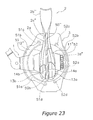
- Fig. 23 is a rear view of the spinning reel in accordance with another preferred embodiment (k) of the present invention corresponding to Fig. 3; and
- Fig. 24 is a cross-sectional side view of a reel unit of the spinning reel in accordance with another preferred embodiment (a) of the present invention corresponding to Fig. 4.
-
- Selected embodiments of the present invention will now be explained with reference to the drawings. It will be apparent to those skilled in the art from this disclosure that the following descriptions of the embodiments of the present invention are provided for illustration only and not for the purpose of limiting the invention as defined by the appended claims and their equivalents.
- A spinning reel in accordance with the present invention includes a guard member. The guard member has a plate-shaped embedded portion in at least one of the reel unit and the rotor, and a protruding portion protruding from the outer peripheral surface of one of the reel unit and the rotor, and connectedly formed with the embedded portion. Therefore, scratching of the reel unit or the rotor is prevented when the spinning reel is placed on the ground.
- Figs. 1-3 show a spinning reel in accordance with a preferred embodiment of the present invention. The spinning reel has a
reel unit 2 that has ahandle 1 and is fitted to a fishing rod, arotor 3 disposed on a front part of thereel unit 2, and aspool 4 disposed on the front part of therotor 3. Therotor 3 is rotatively mounted to thereel unit 2 to wind fishing line onto the spool in response to rotation of thehandle 1. Thespool 4 is mounted to thereel unit 2 to be capable of back-and-forth movement relative thereto. - The
reel unit 2 is made of, for example, a magnesium alloy, and includes areel body 2a and an approximately T-shapedrod attachment portion 2b that extends upward from thereel body 2a shown in Fig 1. Inside of thereel body 2a, a rotation transmission mechanism and an oscillating mechanism (not shown) for moving thespool 4 back and forth relative to thereel body 2a in synchronization with the rotation of therotor 3 of thehandle 1 are provided. - As seen in Figs. 1 and 2, the
reel body 2a further includes abody member 11 and alid member 12. An opening is provided on the side of thebody member 11. A cranking mechanism and the oscillation mechanism (not shown) are installed inside thebody member 11. Thelid member 12 is fastened to thebody member 11 by at least one screw to cover the opening of thebody member 11. Thebody member 11 is formed unitarily with therod attachment leg 2b.Inner cover members body member 11 and thelid member 12, respectively, at a lower rear end portion of thereel body 2a.Outer cover members inner cover members outer cover members first guard member 50 is a plate member embedded in arear end portion 11a of thebody member 11 and the rear end portion 2b1 of therod attachment leg 2b, such that theguard member 50 can contact the ground when the spinning reel is placed thereon. - The
inner cover members outer cover member body member 11 and thelid member 12, as shown in Figs. 1-3. As shown in Fig. 7, on the interior orbody member 11 side, theinner cover 14a is mounted to and in agroove portion 2c formed in thebody member 11 as described below. Agroove portion 14c with a generally U-shaped cross-sectional shape is formed in theinner cover 14a so that thefirst guard member 50 is embedded therein. Theinner cover member 14a is fastened together with thefirst guard member 50 to thebody member 11 by interposing theinner cover 14a between thefirst guard member 50 and thebody member 11 when thefirst guard member 50 is fastened to thebody member 11. Additionally, theouter cover members inner cover members - As shown in Figs. 3 and 4, the
first guard member 50 is a generally L-shaped member when viewed from the side, and extends from therod attachment leg 2b to therear end portion 11a and thelower end portion 11b of thebody member 11. Further, thefirst guard member 50 is formed by T-slot processing. Thefirst guard member 50 includes a plate-shaped embeddedportion 50a (see Fig. 4) embedded in thegroove portion 2c, and a protrudingportion 50b integrally formed with the embeddedportion 50a as a one-piece unitary member and protruding from the contour of therod attachment leg 2b and the rear andlower end portions body member 11. Thefirst guard member 50 is a plate-shaped member with a generally U-shaped cross-sectional shape made of a hard material including a hard metal such as a stainless steel alloy. - As shown in Fig. 4, the
body member 11 includes throughholes hole 2f, apositioning pin 2g, and awall portion 2h. The throughholes body member 11. The threadedhole 2f is formed at an inner periphery side of the throughhole 2d. Thepositioning pin 2g is arranged at an inner periphery side of the throughhole 2e and protrudes therefrom. Thewall portion 2h is disposed to have a wall shape surrounding the periphery of the threadedhole 2f in the rear portion. Thewall portion 2h is disposed to come in contact with a backside surface of thelid member 12 when thelid member 12 is mounted. Thus, it is possible to provide watertight sealing inside. Thefirst guard member 50 further includes anattachment portion 50c protruding toward the inner periphery side in the rear portion. A throughhole 50e is formed at the end part of theattachment portion 50c. Theattachment portion 50c fastens thefirst guard member 50 to thebody member 11 with a screw member (not shown) that passes through the throughhole 2d aligning the throughhole 50e with the threadedhole 2f. In addition, thefirst guard member 50 includes apositioning portion 50d protruding toward the inner periphery side in the lower portion. A throughhole 50f is formed at the end part of thepositioning portion 50d. Thepositioning portion 50d is inserted in the throughhole 2e to position thefirst guard member 50 relative to thebody member 11 by inserting thepositioning pin 2g into the throughhole 50f. - The
rotor 3 includes, as shown in Figs 1, 2, and 3, acylindrical portion 20 rotatably mounted to areel unit 2, afirst rotor arm 21 and asecond rotor arm 22 furnished sideways on thecylindrical portion 20 opposing each other, and abail arm 23 pivotably attached to thefirst rotor arm 21 and thesecond rotor arm 22 for guiding the line. - The
cylindrical portion 20 is preferably made of a magnesium alloy or an aluminum alloy for example, and has a ring-like large-diameter portion 20a that is diametrically larger than the rest of thecylindrical portion 20. The first and thesecond rotor arms cylindrical portion 20 and formed on opposite positions on the outer circumferential surface of the large-diameter portion 20a. The first andsecond rotor arms second connection portions second arm portions second cover portions second connection portions diameter portion 20a at opposite positions on the outer circumferential surface of the large-diameter portion 20a. The pair of the first andsecond arm portions second connection portions cylindrical portion 20. The first andsecond cover portions second connection portions second arm portions second connection portions diameter portion 20a, and taper off radially. The first andsecond arm portions second connection portions second cover portions second cover portions second connection portions second arm portions second cover portions second connection portions second arm portions second rotor arm 22 further includes a generally quadrilateral-shapedhole portion 24c penetrating from an inside surface of thesecond arm portion 22b to an outer surface of thesecond cover portion 24b. In addition, guard members 51-53 are plate members embedded in two locations on the outer peripheral portion of thecylindrical portion 20 and the outer peripheral portion of thesecond rotor arm 22, which can come into contact with the ground when the spinning reel is placed thereon. The second andthird guard members cylindrical portion 20. As shown in Figs. 1, 2, 5 and 6, thefourth guard member 53 is embedded in thesecond arm portion 22b and thesecond cover portion 24b along the longitudinal direction. - As shown in Figs. 5 and 6, the
fourth guard member 53 is embedded in first andsecond groove portions hole portion 24c respectively. Thefourth guard member 53 is mounted from the front end to the rear end of thehole portion 24c to connect the front end portion to the rear end portion of thehole portion 24c. Thefourth guard member 53 includes a plate-shaped embeddedportion 53a (see Fig. 6) embedded in the first andsecond groove portions fourth guard member 53 also includes a protrudingportion 53b protruding from the outer peripheral surfaces of thefirst arm portion 21b and thefirst cover portion 24a so that a part of an end surface of the embeddedportion 53a extends in the form of a line-segment along the contact surface. Thefourth guard member 53 is a plate-shaped member with a generally U, L. or E shaped cross-sectional shape made of a hard metal such as a stainless steel alloy. Anotch portion 53e is formed in the embeddedportion 53a embedded in thefirst groove portion 22c such that a screw attachment portion of a secondbail supporting member 26, shown in Fig. 2 and described later, will not be attached to theguard member 53. The embeddedportion 53a embedded in thefirst groove portion 22c is positioned by a protrudingportion 22f formed on thesecond arm portion 22b. The embeddedportion 53a is fastened to thesecond groove portion 22d by pressing the embeddedportion 53a with ascrew member 53h through aspacer member 53g. Thespacer member 53g is made of a synthetic resin, for example. Interposing thespacer member 53g can prevent wobble of thefourth guard member 53. - As shown in Fig. 3, the second and
third guard members portions portions rotor 3. The second andthird guard members third guard members cylindrical portion 20 by screw members or pin members (not shown) inserted into a pair ofattachment portions attachment portions respective guard members - Referring now to Figs. 1 and 2, the
bail arm 23 guides fishing line onto thespool 4. Thebail arm 23 has first and secondbail support members curved bail 29. The first and secondbail support members rotor arms bail support member 25. The fixed shaft cover is oppositely disposed between the firstbail support member 25 and the line controller 27. Thecurved bail 29 is made of a wire rod that links the secondbail support member 26 to the fixed shaft cover.
The firstbail support member 25 is pivotably mounted at the outer side of thefirst rotor arm 21, while the secondbail support member 26 is pivotably mounted on the inner side of thesecond rotor arm 22. - The
spool 4 includes abobbin trunk 4a, askirt 4b, and aflange portion 4c. Thebobbin trunk 4a is provided to wind around its circumference fishing line guided by thebail arm 23. Theskirt 4b, which is arranged on the rear of thebobbin trunk 4a between thefirst rotor arm 21 and thesecond rotor arm 22, has a larger diameter than that of thebobbin trunk 4a. Theflange portion 4c is arranged on the front of thebobbin trunk 4a. Thespool 4 moves backward and forward relative to thereel body 2a in synchronization with rotation of therotor 3, and uniformly winds fishing line guided by thebail arm 23 onto the circumferential surface of thespool 4. - As seen in Figs. 1-4 and 6, the guard members 50-53 are mounted to the spinning reel as constituted above. The guard members 50-53 include the plate-shaped embedded
portions 50a-53a and the protrudingportions 50b-53b. The plate-shaped embeddedportions 50a-53a are respectively embedded in: from therod attachment leg 2b to the rear end portion and the lower and portion of thereel unit 2, opposite sides on the outer peripheral portion of the cylindrical portion 30, and the outer peripheral portion of thesecond rotor arm 22. The aforementioned locations normally contact the ground when the spinning reel is placed thereon. The protrudingportions 50b-53b protrude from the outer portion surfaces, so as to contact the ground when the reel is placed thereon. In this case, since the protrudingportions 50b-53b protrude from the outer surfaces of thereel unit 2 or therotor 3, surfaces of the reel unit and the rotor that easily comes into contact with the ground in a conventional structure do not directly touch the ground. Thus, scratching of thereel unit 2 or therotor 3 is prevented even when the spinning reel is placed on the ground. - Alternate embodiments will now be explained. In view of the similarity between the first and alternate embodiments, the parts of the alternate embodiments that are identical to the parts of the first embodiment will be given the same reference numerals as the parts of the first embodiment. Moreover, the descriptions of the parts of the second embodiment that are identical to the parts of the first embodiment may be omitted for the sake of brevity.
- (a) In the first embodiment, the
rotor 3 with the first andsecond cover portions second cover portions diameter portion 20a may be omitted. - (b) In the first embodiment, the
first guard member 50 is embedded in thegroove portion 2c of thebody member 11, however, thefirst guard member 50 may be embedded in a groove portion formed in thelid member 12. Additionally, in Fig. 22, the first guard member 50' is embedded in agroove portion 2c' formed in ajoint portion 2m' between the body member 11' and the lid member 12'. Furthermore, in Fig. 23, thelid portion 12" is formed integrally with therod attachment portion 2b", and theguard member 50" is embedded in thelid member 12". - (c) In the first embodiment, the guard members 50-53 are made of a hard metal such as a stainless steel alloy. However, the guard members 50-53 are not limited to this kind of material. The guard members 50-53 may be made of a hard synthetic resin.
- (d) In the first embodiment, as shown in Figs. 2 and 3, the guard members 50-53 are embedded in the
reel unit 2 from therod attachment leg 2b to therear end portion 11a and thelower end portion 11b, on the opposite portions on the outer circumference of the cylindrical portion 30, and the outer portion of thesecond rotor arm 22. However, locations in which the guard members 50-53 are embedded are not limited to these locations. A guard member may be embedded in any location that can come into contact with the ground when the spinning reel is placed on the ground. For example, as shown in Fig. 8, afourth guard member 54 is a plate member embedded in the outer peripheral portion of thefirst rotor arm 21. - (e) As shown in Fig. 4, in the first embodiment, the
first guard member 50 is fastened to thebody member 11 at one location by theattachment portion 50c that is formed at the rear portion of theguard member 50 and protruding toward the inner side. However, as shown in Fig. 9, thefirst guard member 50 may be fastened at two locations additionally by anattachment portion 50g with a throughhole 50h located in the rear portion of thereel unit 2. Thereel unit 2 has two throughholes 2d' through which theattachment portion 50g extends inwardly. - (f) As shown in Figs. 3, 4, and 6, in the first embodiment, the protruding
portions 50b-53b protrude so that the end surfaces thereof extend in the form of a line-segment. However the present invention is not limited to this configuration. For example, as shown in Figs. 10 and 11, a protrudingportion 750b may be arranged along the outer contour of the rear end portion and the lower end portion of thereel body 2 so as to extend laterally in a direction transverse to the length of theguard member 750. More specifically the protrudingportion 750b may extend from the end of the embeddedportion 750a toward both sides of the embeddedportion 750a along the contour of the rear end portion and the lower end portion of the reel body. The embeddedportion 750a is a plate-shaped member to be embedded in thegroove portion 2c. The embeddedportion 750a and the protrudingportion 750b are preferably integrally formed, preferably using a hard metal such as a stainless steel alloy or a synthetic resin to form a unitary member. The protrudingportion 750b protrudes from the end of the embeddedportion 750a toward both ends in a generally symmetrical shape so that thefirst guard member 750 has a generally T-shaped cross-sectional shape. In this case, since the protrudingportion 750b covers a wide area of the contact surface of thereel unit 2 and therod attachment portion 2b, it is possible to enhance the prevention of scratches on thereel unit 2. Furthermore, the protrudingportion 750b is not limited to this shape. For example, as shown in Fig. 12, the protrudingportion 850b can have a generally crescent-shaped cross-sectional shape. In other words, the length of the protrudingportion 850b can be greater than, less than, or equal to the length of the embeddedportion 850a. - (g) In the embodiment (f) mentioned above, the embedded
portion 50a and the protrudingportion 50b are integrally formed of a metal or a synthetic resin as unitary member. However, the present invention is not limited to this configuration. The embedded portion and the protruding portion may be separately formed of different materials. For example, as shown in Fig. 13, the embeddedportion 150a can be made of a hard metal such as a stainless steel alloy, and the protrudingportion 150b can be made of a synthetic resin. The protrudingportion 50b made of a synthetic resin may be insert-molded into the embeddedportion 50a made of a metal. In an alternate case, the protrudingportion 150b may be bonded to the embeddedportion 150a by insert-molding the protrudingportion 150b in a diffusion layer, where a fine triazine thiol powder is diffused by an electrodeposition plating process on the surface of the embeddedportion 150a made of a metal. In this case, the embeddedportion 150a made of a hard metal can maintain its strength at a high level, while the protrudingportion 150b made of a synthetic resin can be formed easily along the outer surface of thereel unit 2. In addition, although not illustrated, the embeddedportion 150a can be made of a synthetic rein, and the protrudingportion 150b can be made of a hard metal such as a stainless steel alloy. - (h) In the first embodiment, as shown in Fig. 4, the
positioning pin 2g is formed on thebody member 11 of thereel body 2a so as to protrude from thebody member 11. However, apositioning pin 202g may be detachably mounted to thebody member 11 as shown in Figs. 14 and 15. In this case, for example, a recessedportion 202i is formed adjacent to the through hole 202e on the lower portion of thebody member 11. Thepositioning pin 202g is mounted to the recessedportion 202i so that the tip of thepositioning pin 202g protrudes from the recessedportion 202i. Thus, the first guard member 250 can be positioned by inserting the protruding portion of thepositioning pin 202g into the throughhole 50f formed in thepositioning portion 50d of thefirst guard member 50. As shown enlarged in Fig. 16, thepositioning pin 202g includes acolumnar body portion 202j, a base end of which is mounted to the recessedportion 202i, and aknob portion 202k, which protrudes toward the tip end side in a generally semi-columnar shape. Theknob portion 202k facilitates easy grasping by a thumb and a finger. Theknob portion 202k is formed unitarily with thebody portion 202j by removing a part of a columnar member. In this case, since thepositioning pin 202g can be detached from the recessedportion 202i by picking up theknob portion 202k with a thumb and a finger, thepositioning pin 202g can be easily attached and detached to the recessedportion 202i. - (i) In the first embodiment, as shown in Fig. 3, the second and
third guard members cylindrical portion 20 by inserting screw members or pin members into theattachment portions third guard members contact portions 303a and 303b, and a pair ofcontact portions cylindrical portion 20. In this configuration, when the second andthird guard members rotor 3 into thecylindrical portion 20, the pair ofattachment portions attachment portions contact portions 303a and 303b, and the pair ofcontact portions third guard members attachment portions attachment portions contact portions 303a and 303b, and the pair ofcontact portions third guard members attachment portions attachment portions third guard members rotor 3. Furthermore, when the second andthird guard members - (j) In the first embodiment, as shown in Fig. 3, the second and
third guard members rotor 3 surface that would normally contact the ground from being scratched. However, the shapes (length in the width direction, or thickness) or the mass of the second andthird guard members rotor 3. - Further, at least one of the second and
third guard members first rotor arm 21 side and thesecond rotor arm 22 side in order to maintain the rotational balance of therotor 3. For example, thesecond guard member 51 can have a width that differs between thefirst rotor arm 21 side and thesecond rotor arm 22 side. Specifically, as shown in Fig. 18, the second guard member 451 includes a narrower portion 451e formed at thefirst rotor arm 21 side to have a narrower width. The second guard member 451 of Fig. 18 also has awider portion 451f formed at thesecond rotor arm 22 side to have a wider width β than the width α of the narrower portion 51e. The widths in this case are lengths transverse to the axial direction of therotor 3. In another case, as shown in Fig. 19, thesecond guard member 551 includes athinner portion 551g formed at thefirst rotor arm 21 side, and athicker portion 551h formed at thesecond rotor arm 22 side to be thicker than thethinner portion 551g. In this case, since the narrower portion 451e or thethinner portion 551g is formed at thefirst rotor arm 21 side of thesecond guard member 451 or 551, the mass at thefirst rotor arm 21 side is smaller than that of thesecond rotor arm 22 side of thesecond guard member 51. On the other hand, since thefirst rotor arm 21 includes a mechanism such as thebail arm 23 inside, the mass of thefirst rotor arm 21 side of therotor 3 is greater than that of thesecond rotor arm 22 side of thesecond rotor 3. Accordingly, forming the narrower portion 451e or thethinner portion 551g at thefirst rotor arm 21 side of thesecond guard member 51 can balance mass of therotor 3 and theguard member 451 or 551 as a whole between thefirst rotor arm 21 side and thesecond rotor arm 22 side. Therefore, it is possible to maintain rotational balance of therotor 3. - (k) In the first embodiment, as shown in Fig. 6, the
fourth guard member 53 is mounted from the front end to the rear end of thehole portion 24c of thesecond cover portion 24b to attach the front end portion and the rear end portion of thefourth guard member 53 to thehole portion 24c. On the other hand, as shown in Figs. 20 and 21, thesecond cover portion 624b includes throughholes portion 53a is inserted, a throughhole 624f, and acontact portion 624g. The throughholes first groove portion 22c. The throughhole 624f, into which the embeddedportion 53a is inserted, is formed at a location opposed to thesecond groove portion 22d. Thecontact portion 624g, with which the embeddedportion 53a contacts, is formed between the throughholes fourth guard member 53 is mounted, the backside surface of the embeddedportion 53a is in contact with thecontact portion 624g of thesecond cover portion 624b, and thefourth guard member 53 can press thesecond cover portion 624b. Thus, the end part portion of thesecond cover portion 624b can be aligned. In addition, since a contact portion 24h, with which the embeddedportion 53a is in contact, is further formed at the rear side of the throughhole 624e, the end part of thesecond cover portion 624b can be stably supported to thesecond rotor arm 22 when thesecond cover portion 624b is fastened with a screw member. - (l) In the first embodiment, as shown in Figs. 3, 4, and 6, the embedded
portions 50a-53a are embedded in thereel unit 2 from therod attachment leg 2b of to the rear end portion and the lower and portion of thereel unit 2, to therotor 3 on the opposite sides of the outer peripheral portion of the cylindrical portion 30, and the outer peripheral portion of thesecond rotor arm 22, such that the guard members 50-53 can contact the ground when the spinning reel is placed thereon. However, the present invention is not limited to these arrangements. For example, the embeddedportion 50a may be embedded in a location away from the rear end portion and the lower and portion of thereel unit 2. In this configuration, the protrudingportion 50b is designed to be thick enough to be in contact with the ground. Thus, the surface of thereel unit 2 does not come in direct contact with the ground. - As used herein, the following directional terms "forward, rearward, above, downward, vertical, horizontal, below, and transverse" as well as any other similar directional terms refer to those directions of a device equipped with the present invention. Accordingly, these terms, as utilized to describe the present invention should be interpreted relative to a device equipped with the present invention.
- The term "configured" as used herein to describe a component, section or part of a device includes hardware and/or software that is constructed and/or programmed to carry out the desired function.
- Moreover, terms that are expressed as "means-plus function" in the claims should include any structure that can be utilized to carry out the function of that part of the present invention.
- The terms of degree such as "substantially," "about," and "approximately" as used herein mean a reasonable amount of deviation of the modified term such that the end result is not significantly changed. For example, these terms can be construed as including a deviation of at least ± 5% of the modified term if this deviation would not negate the meaning of the word it modifies.
- This application claims priority to Japanese Patent Application Nos. 2003-296346 and 2003-411638. The entire disclosures of Japanese Patent Application Nos. 2003-296346 and 2003-411638 are hereby incorporated herein by reference.
- While only selected embodiments have been chosen to illustrate the present invention, it will be apparent to those skilled in the art from this disclosure that various changes and modifications can be made herein without departing from the scope of the invention as defined in the appended claims. Furthermore, the foregoing descriptions of the embodiments according to the present invention are provided for illustration only, and not for the purpose of limiting the invention as defined by the appended claims and their equivalents. Thus, the scope of the invention is not limited to the disclosed embodiments.
Claims (21)
- A spinning reel comprising:a reel unit (2) being adapted to be mounted on a fishing rod;a handle being rotatably attached to said reel unit (2);a spool (4) being movably mounted to said reel unit (2) to move back and forth relative to said reel unit (2), said spool (4) having an outer peripheral portion on which fishing line is adapted to be wound and unwound;a rotor (3) being rotatably mounted to said reel unit (2), said rotor (3) being adapted to wind said fishing line onto said spool (4) in response to rotation of said handle; anda guard member (50,51,52,53) having a plate-shaped embedded portion (50a,51a,52a,53a) embedded in at least one of said reel unit (2) and said rotor (3), and a protruding portion (50b,51b,52b,53b) protruding from an outer surface of said one of said reel unit (2) and said rotor (3), said protruding portion (50b,51b,52b,53b) being connectedly formed with said embedded portion (50a,51a,52a,53a).
- The spinning reel according to claim 1, wherein
said reel unit (2) includes a reel body (2a) and a rod attachment leg (2b) extending diagonally from said reel body (2a) so as to be integral with said reel body (2a), a fishing rod being adapted to be coupled to said rod attachment leg (2b), and
said guard member (50) is embedded in at least one of a rear end portion of said reel body (2a), a lower end portion of said reel body (2a), and a rear end portion of said rod attachment leg (2b). - The spinning reel according to claim 1 or 2, wherein
said reel unit (2) includes a body member (11), and a lid member (12) fastened to said body member (11) with a screw, a groove portion (2c,14c) being formed in at least one of said body member (11) and said lid member (12), and
said guard member (50) is embedded in said groove portion (2c,14c). - The spinning reel according to claim 1 or 2, wherein
said reel unit (2) includes a body member (11'), and a lid member (12') fastened to said body member (11') with a screw, a groove (2c') portion being formed in a joint portion (2m') between said body member (11') and said lid member (12'), and
said guard member (50') is embedded in said groove portion (2c') formed in said joint portion (2m') between said body member (11') and said lid member (12'). - The spinning reel according to any of claims 1-4, wherein
said rotor (3) further includes a cylindrical portion (20), rotor arms (21, 22), and a bail arm (23), said cylindrical portion (20) being rotatably mounted to said reel unit (2), said rotor arms (21,22) arranged on said cylindrical portion (20) opposite each other and connectedly formed with a rear side outer peripheral surface of said cylindrical portion (20), said bail arm (23) being pivotably mounted to fore-ends of said rotor arms (21,22) to guide said fishing line to said spool (4), and
said guard member (51,52,53) is embedded in at least one of an outer peripheral portion of said cylindrical portion (20), an outer peripheral portion of said rotor arm (22), and an outer peripheral portion of said bail arm (23). - The spinning reel according to claim 5, wherein
at least one of said rotor arms (21,22) being provided with a hole portion (24c) that penetrates from an inner periphery to an outer peripheral portion of said rotor arm (22), and first and second groove portions (22c,22d) respectively formed on front and rear sides of said hole portion (24c), and
said guard member (53) is embedded in said first and second groove portions (22c,22d)to connect said front end portion to said rear end portion of said hole portion (24c). - The spinning reel according to any of claims 1-6, wherein
said guard member (50,51,52) is fastened to at least one of said reel unit (2) and said rotor (3) with a screw. - The spinning reel according to any of claims 1-7, wherein
said guard member (50, 51, 52, 53) is made of a hard material. - The spinning reel according to any of claims 1-7, wherein
said guard member (50, 51, 52, 53) is a metal member. - The spinning reel according to any of claims 1-7, wherein
said guard member (50, 51, 52, 53) is a synthetic resin member. - The spinning reel according to any of claims 1-10, wherein
a part of said protruding portion (50b,51b,52b,53b), extends linearly to define a flat surface. - The spinning reel according to any of claims 1-11, wherein
said protruding portion (50b,51b,52b,53b) has a greater width than a width of said embedded portion (50a,51a,52a,53a), said protruding portion (50b,51b,52b,53b) extending along a contour of the outer surface of said one of said reel unit (2) and said rotor (3) in a direction transverse to a length of said guard member (50, 51, 52, 53). - The spinning reel according to claim 12, wherein
said protruding portion (50b,51b,52b,53b) extends on both sides of said embedded portion (50a,51a,52a,53a) along a contour of the outer surface of said one of said reel unit (2) and said rotor (3). - The spinning reel according to any of claims 1-13, wherein
said protruding portion (50b,51b,52b,53b) is formed unitarily with said embedded portion (50a,51a,52a,53a). - The spinning reel according to any of claims 1-13, wherein
said protruding portion (50b,51b,52b,53b) and said embedded portion (50a,51a,52a,53a) are formed of different materials. - The spinning reel according to claim 15, wherein
one of said protruding portion (50b,51b,52b,53b) and said embedded portion (50a,51a,52a,53a) is made of a synthetic resin, and the other one of said protruding portion (50b,51b,52b,53b) and said embedded portion (50a,51a,52a,53a) is made of a metal. - The spinning reel according to claim 16, wherein
the one of said protruding portion (50b,51b,52b,53b) and said embedded portion (50a,51a,52a,53a) made of a synthetic resin is bonded to a surface of the other one of said protruding portion (50b,51b,52b,53b) and said embedded portion (50a,51a,52a,53a) made of a metal. - The spinning reel according to any of claims 1-17, wherein
said embedded portion (50a,51a,52a,53a) is embedded in at least one of said reel unit (2) and said rotor (3) such that said protruding portion (50b,51b,52b,53b) contacts a ground when said spinning reel is placed on the ground. - The spinning reel according to any of claims 1-18, wherein
said guard member (451) has a narrower portion (451e) and a wider portion (451f), said wider portion (451f) having a width that is wider than a width of said narrower portion (451e). - The spinning reel according to any of claims 1-19, wherein
said guard member (551) has a thicker portion (551g) and a thinner portion (551h), said thicker portion (551g) having a thickness that is greater than a thickness of said thinner portion (551h). - The spinning reel according to any of claims 1-20, wherein
said guard member (50, 51, 52, 53) is a plate member.
Applications Claiming Priority (4)
| Application Number | Priority Date | Filing Date | Title |
|---|---|---|---|
| JP2003296346 | 2003-08-20 | ||
| JP2003296346 | 2003-08-20 | ||
| JP2003411638A JP4314108B2 (en) | 2003-08-20 | 2003-12-10 | Spinning reel |
| JP2003411638 | 2003-12-10 |
Publications (2)
| Publication Number | Publication Date |
|---|---|
| EP1508275A1 true EP1508275A1 (en) | 2005-02-23 |
| EP1508275B1 EP1508275B1 (en) | 2005-12-28 |
Family
ID=34067418
Family Applications (1)
| Application Number | Title | Priority Date | Filing Date |
|---|---|---|---|
| EP04254816A Not-in-force EP1508275B1 (en) | 2003-08-20 | 2004-08-11 | Spinning reel |
Country Status (10)
| Country | Link |
|---|---|
| US (2) | US7070138B2 (en) |
| EP (1) | EP1508275B1 (en) |
| JP (1) | JP4314108B2 (en) |
| KR (1) | KR101058365B1 (en) |
| CN (1) | CN100425133C (en) |
| DE (1) | DE602004000287T2 (en) |
| ES (1) | ES2256823T3 (en) |
| MY (1) | MY128797A (en) |
| SG (1) | SG109544A1 (en) |
| TW (1) | TWI312661B (en) |
Cited By (1)
| Publication number | Priority date | Publication date | Assignee | Title |
|---|---|---|---|---|
| EP2745687A1 (en) * | 2012-12-20 | 2014-06-25 | Shimano Inc. | Spinning reel body and spinning reel |
Families Citing this family (13)
| Publication number | Priority date | Publication date | Assignee | Title |
|---|---|---|---|---|
| US7286250B2 (en) * | 2000-04-27 | 2007-10-23 | Canon Kabushiki Kaisha | Print control apparatus and method, and print system |
| US7066419B2 (en) * | 2003-09-10 | 2006-06-27 | Shimano Inc. | Reel unit for spinning reel |
| SG116585A1 (en) * | 2004-04-13 | 2005-11-28 | Shimabno Inc | Reel unit for dual-bearing reel. |
| JP2006304675A (en) * | 2005-04-28 | 2006-11-09 | Daiwa Seiko Inc | Spinning reel for fishing |
| JP4607743B2 (en) * | 2005-11-16 | 2011-01-05 | グローブライド株式会社 | Double bearing type reel for fishing |
| US7275705B1 (en) | 2006-09-07 | 2007-10-02 | Shakespeare Company, Llc | Spinning reel having two-piece frame and leg assembly with concealable attachment points |
| JP5049563B2 (en) * | 2006-11-20 | 2012-10-17 | 株式会社シマノ | Fishing reel control knob |
| JP4884343B2 (en) * | 2007-09-14 | 2012-02-29 | 株式会社シマノ | Spinning reel body |
| JP6132543B2 (en) | 2012-12-20 | 2017-05-24 | 株式会社シマノ | Spinning reel |
| EP2745686B1 (en) | 2012-12-20 | 2017-01-04 | Shimano Inc. | Rotor for spinning reel |
| JP6389370B2 (en) * | 2014-03-28 | 2018-09-12 | グローブライド株式会社 | Fishing spinning reel |
| WO2020257651A1 (en) | 2019-06-21 | 2020-12-24 | Biz Outdoors, Inc. | Left handed fishing reel |
| JP7211396B2 (en) | 2020-04-28 | 2023-01-24 | トヨタ自動車株式会社 | Control device for fan coupling device |
Citations (2)
| Publication number | Priority date | Publication date | Assignee | Title |
|---|---|---|---|---|
| JPH11137133A (en) * | 1997-11-11 | 1999-05-25 | Shimano Inc | Spinning reel |
| JP2003274816A (en) * | 2002-03-26 | 2003-09-30 | Daiwa Seiko Inc | Spinning reel for fishing |
Family Cites Families (11)
| Publication number | Priority date | Publication date | Assignee | Title |
|---|---|---|---|---|
| JP2550410Y2 (en) | 1991-10-31 | 1997-10-15 | 株式会社シマノ | Spinning reel |
| JP2001136874A (en) | 1999-11-11 | 2001-05-22 | Shimano Inc | Rotor of spinning reel |
| JP4572033B2 (en) | 2000-12-19 | 2010-10-27 | 株式会社シマノ | Spinning reel rotor |
| JP2002218874A (en) | 2001-01-22 | 2002-08-06 | Daiwa Seiko Inc | One-sided baring fishing reel |
| JP3913510B2 (en) * | 2001-10-04 | 2007-05-09 | 株式会社シマノ | Fastening structure for fishing parts |
| JP2003210081A (en) * | 2002-01-22 | 2003-07-29 | Shimano Inc | Part assembly of fishing reel |
| JP2003225039A (en) * | 2002-02-05 | 2003-08-12 | Shimano Inc | Reel body of spinning reel |
| US20030146324A1 (en) * | 2002-02-06 | 2003-08-07 | Shih-Yuan Yeh | Fishing reel with a replaceable casing |
| JP4015901B2 (en) * | 2002-07-31 | 2007-11-28 | 株式会社シマノ | Spinning reel body |
| JP3746033B2 (en) * | 2002-10-25 | 2006-02-15 | 株式会社シマノ | Spinning reel body |
| JP2004236568A (en) * | 2003-02-05 | 2004-08-26 | Shimano Inc | Reel body of spinning reel |
-
2003
- 2003-12-10 JP JP2003411638A patent/JP4314108B2/en not_active Expired - Fee Related
-
2004
- 2004-07-26 SG SG200404372A patent/SG109544A1/en unknown
- 2004-07-28 TW TW093122571A patent/TWI312661B/en not_active IP Right Cessation
- 2004-07-29 US US10/901,117 patent/US7070138B2/en active Active
- 2004-08-02 MY MYPI20043108A patent/MY128797A/en unknown
- 2004-08-11 EP EP04254816A patent/EP1508275B1/en not_active Not-in-force
- 2004-08-11 ES ES04254816T patent/ES2256823T3/en active Active
- 2004-08-11 DE DE602004000287T patent/DE602004000287T2/en active Active
- 2004-08-18 KR KR1020040065045A patent/KR101058365B1/en active IP Right Grant
- 2004-08-20 CN CNB2004100578605A patent/CN100425133C/en not_active Expired - Fee Related
-
2006
- 2006-03-30 US US11/392,638 patent/US7293732B2/en active Active
Patent Citations (2)
| Publication number | Priority date | Publication date | Assignee | Title |
|---|---|---|---|---|
| JPH11137133A (en) * | 1997-11-11 | 1999-05-25 | Shimano Inc | Spinning reel |
| JP2003274816A (en) * | 2002-03-26 | 2003-09-30 | Daiwa Seiko Inc | Spinning reel for fishing |
Non-Patent Citations (2)
| Title |
|---|
| PATENT ABSTRACTS OF JAPAN vol. 1999, no. 10 31 August 1999 (1999-08-31) * |
| PATENT ABSTRACTS OF JAPAN vol. 2003, no. 12 5 December 2003 (2003-12-05) * |
Cited By (3)
| Publication number | Priority date | Publication date | Assignee | Title |
|---|---|---|---|---|
| EP2745687A1 (en) * | 2012-12-20 | 2014-06-25 | Shimano Inc. | Spinning reel body and spinning reel |
| KR20140080405A (en) * | 2012-12-20 | 2014-06-30 | 가부시키가이샤 시마노 | Reel body and spinning reel |
| US8939391B2 (en) | 2012-12-20 | 2015-01-27 | Shimano Inc. | Spinning reel body and spinning reel |
Also Published As
| Publication number | Publication date |
|---|---|
| KR20050020660A (en) | 2005-03-04 |
| TWI312661B (en) | 2009-08-01 |
| SG109544A1 (en) | 2005-03-30 |
| US20050040269A1 (en) | 2005-02-24 |
| CN100425133C (en) | 2008-10-15 |
| ES2256823T3 (en) | 2006-07-16 |
| US7293732B2 (en) | 2007-11-13 |
| US20060186242A1 (en) | 2006-08-24 |
| CN1582652A (en) | 2005-02-23 |
| EP1508275B1 (en) | 2005-12-28 |
| TW200517052A (en) | 2005-06-01 |
| MY128797A (en) | 2007-02-28 |
| US7070138B2 (en) | 2006-07-04 |
| DE602004000287T2 (en) | 2006-08-31 |
| JP2005095131A (en) | 2005-04-14 |
| KR101058365B1 (en) | 2011-08-22 |
| JP4314108B2 (en) | 2009-08-12 |
| DE602004000287D1 (en) | 2006-02-02 |
Similar Documents
| Publication | Publication Date | Title |
|---|---|---|
| US7293732B2 (en) | Spinning reel | |
| US7614577B2 (en) | Handle knob and handle assembly for a fishing reel | |
| US7121491B2 (en) | Reel unit for spinning reel | |
| EP1222855A1 (en) | Spool for spinning reel | |
| JP2005095131A5 (en) | ||
| US7118059B2 (en) | Reel unit for spinning reel | |
| US6880776B2 (en) | Reel unit for spinning reel | |
| EP1332671B1 (en) | Spinning Reel Rotor | |
| US6607154B2 (en) | Spool for spinning reel | |
| US6854677B2 (en) | Spinning-reel sounding mechanism | |
| JPH0555875U (en) | Fishing reel | |
| US7118058B2 (en) | Spinning reel rotor | |
| EP1226754B1 (en) | Fishing-line guiding mechanism for spinning reel | |
| JP4022480B2 (en) | Spinning reel body | |
| JP4024478B2 (en) | Single bearing reel | |
| JP4307937B2 (en) | Spinning reel body | |
| EP1486117A2 (en) | Reel unit and cover member for a spinning reel | |
| EP3180977A1 (en) | Spinning reel rotor and spinning reel | |
| JP2004141039A (en) | Spinning reel rotor | |
| JP2004254534A (en) | Spinning reel main body | |
| JP3871299B2 (en) | Single bearing reel for fishing | |
| JP2519202Y2 (en) | Fishing line guide | |
| JP2002142622A (en) | Spinning reel | |
| JP2004229543A (en) | Reel main body for spinning reel |
Legal Events
| Date | Code | Title | Description |
|---|---|---|---|
| PUAI | Public reference made under article 153(3) epc to a published international application that has entered the european phase |
Free format text: ORIGINAL CODE: 0009012 |
|
| AK | Designated contracting states |
Kind code of ref document: A1 Designated state(s): AT BE BG CH CY CZ DE DK EE ES FI FR GB GR HU IE IT LI LU MC NL PL PT RO SE SI SK TR |
|
| AX | Request for extension of the european patent |
Extension state: AL HR LT LV MK |
|
| 17P | Request for examination filed |
Effective date: 20050224 |
|
| GRAP | Despatch of communication of intention to grant a patent |
Free format text: ORIGINAL CODE: EPIDOSNIGR1 |
|
| AKX | Designation fees paid |
Designated state(s): AT BE BG CH CY CZ DE DK EE ES FI FR GB GR HU IE IT LI LU MC NL PL PT RO SE SI SK TR |
|
| GRAS | Grant fee paid |
Free format text: ORIGINAL CODE: EPIDOSNIGR3 |
|
| GRAA | (expected) grant |
Free format text: ORIGINAL CODE: 0009210 |
|
| AK | Designated contracting states |
Kind code of ref document: B1 Designated state(s): AT BE BG CH CY CZ DE DK EE ES FI FR GB GR HU IE IT LI LU MC NL PL PT RO SE SI SK TR |
|
| PG25 | Lapsed in a contracting state [announced via postgrant information from national office to epo] |
Ref country code: PL Free format text: LAPSE BECAUSE OF FAILURE TO SUBMIT A TRANSLATION OF THE DESCRIPTION OR TO PAY THE FEE WITHIN THE PRESCRIBED TIME-LIMIT Effective date: 20051228 Ref country code: LI Free format text: LAPSE BECAUSE OF FAILURE TO SUBMIT A TRANSLATION OF THE DESCRIPTION OR TO PAY THE FEE WITHIN THE PRESCRIBED TIME-LIMIT Effective date: 20051228 Ref country code: FI Free format text: LAPSE BECAUSE OF FAILURE TO SUBMIT A TRANSLATION OF THE DESCRIPTION OR TO PAY THE FEE WITHIN THE PRESCRIBED TIME-LIMIT Effective date: 20051228 Ref country code: CH Free format text: LAPSE BECAUSE OF FAILURE TO SUBMIT A TRANSLATION OF THE DESCRIPTION OR TO PAY THE FEE WITHIN THE PRESCRIBED TIME-LIMIT Effective date: 20051228 Ref country code: BE Free format text: LAPSE BECAUSE OF FAILURE TO SUBMIT A TRANSLATION OF THE DESCRIPTION OR TO PAY THE FEE WITHIN THE PRESCRIBED TIME-LIMIT Effective date: 20051228 Ref country code: SK Free format text: LAPSE BECAUSE OF FAILURE TO SUBMIT A TRANSLATION OF THE DESCRIPTION OR TO PAY THE FEE WITHIN THE PRESCRIBED TIME-LIMIT Effective date: 20051228 Ref country code: SI Free format text: LAPSE BECAUSE OF FAILURE TO SUBMIT A TRANSLATION OF THE DESCRIPTION OR TO PAY THE FEE WITHIN THE PRESCRIBED TIME-LIMIT Effective date: 20051228 Ref country code: AT Free format text: LAPSE BECAUSE OF FAILURE TO SUBMIT A TRANSLATION OF THE DESCRIPTION OR TO PAY THE FEE WITHIN THE PRESCRIBED TIME-LIMIT Effective date: 20051228 Ref country code: RO Free format text: LAPSE BECAUSE OF FAILURE TO SUBMIT A TRANSLATION OF THE DESCRIPTION OR TO PAY THE FEE WITHIN THE PRESCRIBED TIME-LIMIT Effective date: 20051228 Ref country code: CZ Free format text: LAPSE BECAUSE OF FAILURE TO SUBMIT A TRANSLATION OF THE DESCRIPTION OR TO PAY THE FEE WITHIN THE PRESCRIBED TIME-LIMIT Effective date: 20051228 |
|
| REG | Reference to a national code |
Ref country code: GB Ref legal event code: FG4D |
|
| REG | Reference to a national code |
Ref country code: CH Ref legal event code: EP |
|
| REG | Reference to a national code |
Ref country code: IE Ref legal event code: FG4D |
|
| REF | Corresponds to: |
Ref document number: 602004000287 Country of ref document: DE Date of ref document: 20060202 Kind code of ref document: P |
|
| PG25 | Lapsed in a contracting state [announced via postgrant information from national office to epo] |
Ref country code: DK Free format text: LAPSE BECAUSE OF FAILURE TO SUBMIT A TRANSLATION OF THE DESCRIPTION OR TO PAY THE FEE WITHIN THE PRESCRIBED TIME-LIMIT Effective date: 20060328 Ref country code: BG Free format text: LAPSE BECAUSE OF FAILURE TO SUBMIT A TRANSLATION OF THE DESCRIPTION OR TO PAY THE FEE WITHIN THE PRESCRIBED TIME-LIMIT Effective date: 20060328 Ref country code: SE Free format text: LAPSE BECAUSE OF FAILURE TO SUBMIT A TRANSLATION OF THE DESCRIPTION OR TO PAY THE FEE WITHIN THE PRESCRIBED TIME-LIMIT Effective date: 20060328 Ref country code: GR Free format text: LAPSE BECAUSE OF FAILURE TO SUBMIT A TRANSLATION OF THE DESCRIPTION OR TO PAY THE FEE WITHIN THE PRESCRIBED TIME-LIMIT Effective date: 20060328 |
|
| PG25 | Lapsed in a contracting state [announced via postgrant information from national office to epo] |
Ref country code: PT Free format text: LAPSE BECAUSE OF FAILURE TO SUBMIT A TRANSLATION OF THE DESCRIPTION OR TO PAY THE FEE WITHIN THE PRESCRIBED TIME-LIMIT Effective date: 20060529 |
|
| PG25 | Lapsed in a contracting state [announced via postgrant information from national office to epo] |
Ref country code: HU Free format text: LAPSE BECAUSE OF FAILURE TO SUBMIT A TRANSLATION OF THE DESCRIPTION OR TO PAY THE FEE WITHIN THE PRESCRIBED TIME-LIMIT Effective date: 20060629 |
|
| REG | Reference to a national code |
Ref country code: CH Ref legal event code: PL |
|
| REG | Reference to a national code |
Ref country code: ES Ref legal event code: FG2A Ref document number: 2256823 Country of ref document: ES Kind code of ref document: T3 |
|
| ET | Fr: translation filed | ||
| RAP2 | Party data changed (patent owner data changed or rights of a patent transferred) |
Owner name: SHIMANO INC. |
|
| PG25 | Lapsed in a contracting state [announced via postgrant information from national office to epo] |
Ref country code: IE Free format text: LAPSE BECAUSE OF NON-PAYMENT OF DUE FEES Effective date: 20060811 |
|
| PG25 | Lapsed in a contracting state [announced via postgrant information from national office to epo] |
Ref country code: MC Free format text: LAPSE BECAUSE OF NON-PAYMENT OF DUE FEES Effective date: 20060831 |
|
| NLT2 | Nl: modifications (of names), taken from the european patent patent bulletin |
Owner name: SHIMANO INC. Effective date: 20060802 |
|
| PLBE | No opposition filed within time limit |
Free format text: ORIGINAL CODE: 0009261 |
|
| STAA | Information on the status of an ep patent application or granted ep patent |
Free format text: STATUS: NO OPPOSITION FILED WITHIN TIME LIMIT |
|
| 26N | No opposition filed |
Effective date: 20060929 |
|
| REG | Reference to a national code |
Ref country code: IE Ref legal event code: MM4A |
|
| PG25 | Lapsed in a contracting state [announced via postgrant information from national office to epo] |
Ref country code: EE Free format text: LAPSE BECAUSE OF FAILURE TO SUBMIT A TRANSLATION OF THE DESCRIPTION OR TO PAY THE FEE WITHIN THE PRESCRIBED TIME-LIMIT Effective date: 20051228 |
|
| PG25 | Lapsed in a contracting state [announced via postgrant information from national office to epo] |
Ref country code: LU Free format text: LAPSE BECAUSE OF NON-PAYMENT OF DUE FEES Effective date: 20060811 Ref country code: TR Free format text: LAPSE BECAUSE OF FAILURE TO SUBMIT A TRANSLATION OF THE DESCRIPTION OR TO PAY THE FEE WITHIN THE PRESCRIBED TIME-LIMIT Effective date: 20051228 |
|
| PG25 | Lapsed in a contracting state [announced via postgrant information from national office to epo] |
Ref country code: CY Free format text: LAPSE BECAUSE OF FAILURE TO SUBMIT A TRANSLATION OF THE DESCRIPTION OR TO PAY THE FEE WITHIN THE PRESCRIBED TIME-LIMIT Effective date: 20051228 |
|
| PGFP | Annual fee paid to national office [announced via postgrant information from national office to epo] |
Ref country code: NL Payment date: 20090816 Year of fee payment: 6 |
|
| REG | Reference to a national code |
Ref country code: NL Ref legal event code: V1 Effective date: 20110301 |
|
| PG25 | Lapsed in a contracting state [announced via postgrant information from national office to epo] |
Ref country code: NL Free format text: LAPSE BECAUSE OF NON-PAYMENT OF DUE FEES Effective date: 20110301 |
|
| PGFP | Annual fee paid to national office [announced via postgrant information from national office to epo] |
Ref country code: ES Payment date: 20110824 Year of fee payment: 8 |
|
| PGFP | Annual fee paid to national office [announced via postgrant information from national office to epo] |
Ref country code: IT Payment date: 20120809 Year of fee payment: 9 |
|
| REG | Reference to a national code |
Ref country code: ES Ref legal event code: FD2A Effective date: 20131018 |
|
| PG25 | Lapsed in a contracting state [announced via postgrant information from national office to epo] |
Ref country code: ES Free format text: LAPSE BECAUSE OF NON-PAYMENT OF DUE FEES Effective date: 20120812 |
|
| PG25 | Lapsed in a contracting state [announced via postgrant information from national office to epo] |
Ref country code: IT Free format text: LAPSE BECAUSE OF NON-PAYMENT OF DUE FEES Effective date: 20130811 |
|
| REG | Reference to a national code |
Ref country code: FR Ref legal event code: PLFP Year of fee payment: 13 |
|
| REG | Reference to a national code |
Ref country code: FR Ref legal event code: PLFP Year of fee payment: 14 |
|
| REG | Reference to a national code |
Ref country code: FR Ref legal event code: PLFP Year of fee payment: 15 |
|
| PGFP | Annual fee paid to national office [announced via postgrant information from national office to epo] |
Ref country code: GB Payment date: 20200729 Year of fee payment: 17 Ref country code: FR Payment date: 20200715 Year of fee payment: 17 |
|
| PGFP | Annual fee paid to national office [announced via postgrant information from national office to epo] |
Ref country code: DE Payment date: 20210630 Year of fee payment: 18 |
|
| GBPC | Gb: european patent ceased through non-payment of renewal fee |
Effective date: 20210811 |
|
| PG25 | Lapsed in a contracting state [announced via postgrant information from national office to epo] |
Ref country code: GB Free format text: LAPSE BECAUSE OF NON-PAYMENT OF DUE FEES Effective date: 20210811 Ref country code: FR Free format text: LAPSE BECAUSE OF NON-PAYMENT OF DUE FEES Effective date: 20210831 |
|
| REG | Reference to a national code |
Ref country code: DE Ref legal event code: R119 Ref document number: 602004000287 Country of ref document: DE |
|
| P01 | Opt-out of the competence of the unified patent court (upc) registered |
Effective date: 20230503 |
|
| PG25 | Lapsed in a contracting state [announced via postgrant information from national office to epo] |
Ref country code: DE Free format text: LAPSE BECAUSE OF NON-PAYMENT OF DUE FEES Effective date: 20230301 |