EP2744703B1 - Système et connecteur d'amarrage - Google Patents
Système et connecteur d'amarrage Download PDFInfo
- Publication number
- EP2744703B1 EP2744703B1 EP12766125.4A EP12766125A EP2744703B1 EP 2744703 B1 EP2744703 B1 EP 2744703B1 EP 12766125 A EP12766125 A EP 12766125A EP 2744703 B1 EP2744703 B1 EP 2744703B1
- Authority
- EP
- European Patent Office
- Prior art keywords
- connector assembly
- mooring
- vessel
- assembly according
- fluid transfer
- Prior art date
- Legal status (The legal status is an assumption and is not a legal conclusion. Google has not performed a legal analysis and makes no representation as to the accuracy of the status listed.)
- Active
Links
Images


Classifications
-
- B—PERFORMING OPERATIONS; TRANSPORTING
- B63—SHIPS OR OTHER WATERBORNE VESSELS; RELATED EQUIPMENT
- B63B—SHIPS OR OTHER WATERBORNE VESSELS; EQUIPMENT FOR SHIPPING
- B63B21/00—Tying-up; Shifting, towing, or pushing equipment; Anchoring
-
- B—PERFORMING OPERATIONS; TRANSPORTING
- B63—SHIPS OR OTHER WATERBORNE VESSELS; RELATED EQUIPMENT
- B63B—SHIPS OR OTHER WATERBORNE VESSELS; EQUIPMENT FOR SHIPPING
- B63B21/00—Tying-up; Shifting, towing, or pushing equipment; Anchoring
- B63B21/50—Anchoring arrangements or methods for special vessels, e.g. for floating drilling platforms or dredgers
-
- B—PERFORMING OPERATIONS; TRANSPORTING
- B63—SHIPS OR OTHER WATERBORNE VESSELS; RELATED EQUIPMENT
- B63B—SHIPS OR OTHER WATERBORNE VESSELS; EQUIPMENT FOR SHIPPING
- B63B27/00—Arrangement of ship-based loading or unloading equipment for cargo or passengers
- B63B27/24—Arrangement of ship-based loading or unloading equipment for cargo or passengers of pipe-lines
Definitions
- the present invention relates generally to mooring systems and connector assemblies for use in mooring system, and in particular to vessel mooring and fluid transfer systems and to connector assemblies for use with such systems.
- the invention has particular but not exclusive application to offshore oil and gas Extended Well Tests (EWTs), Early Production Systems (EPSs), Floating Production Storage and Offtake systems (FPSOs), Floating Storage and Offtake systems (FSOs) and Shuttle Tanker Loading Systems.
- EWTs offshore oil and gas Extended Well Tests
- EPSs Early Production Systems
- FPSOs Floating Production Storage and Offtake systems
- FSOs Floating Storage and Offtake systems
- Shuttle Tanker Loading Systems Shuttle Tanker Loading Systems.
- US 5,944,448 and GB 2,296,904 describe mooring and flowline systems which comprise a three-leg mooring and flexible riser.
- the flexible riser is without rotational couplings, and has a part of its length secured to a mooring pendant. There is therefore a restriction on the number of turns the vessel can make, since turning full circle will effectively twist the fluid riser in the chafe chains around one another.
- the systems of US 5,944,448 and GB 2,296,904 therefore have limited weathervaning capabilities and are prone to fatigue and wear problems.
- GB 2,359,054 describes a similar system in which a riser is secured to a non-swivelling node 18 and a mooring pendant.
- the riser comprises a single rotational coupling.
- the arrangement of GB 2,359,054 is designed to cause the riser pipe to helix around the pendant chain, restricting weathervaning capabilities and inducing fatigue and wear.
- internal turret mooring systems consist of a turret and a turret casing integrated into the hull of a vessel. The two parts are connected via a bearing system which allows the turret casing to rotate around the turret.
- a typical design of an internal turret mooring system enables the connection of risers and associated umbilicals via a swivel stack.
- GB 2285028 is an example of a disconnectable turret mooring system integrated into the bow of a vessel
- WO 03/039946 is an example of a turret for the connection of a buoy to a vessel.
- EP 0656293 describes an alternative internal turret vessel mooring system.
- the document also describes a configuration in which the turret casing is mounted on a structure which extends beyond the bow of the vessel such that the turret is external to the hull (see Figure 1 of EP 0656293 ).
- EP 1796958 is another example of an offshore vessel mooring and riser inboarding system which offers similar functionality to an internal turret but via an external assembly.
- the system comprises a cantilever support mounted on a bow of the vessel. This system provides a gimbal arrangement which enables movement of a turret about three mutually perpendicular axes.
- WO 96/11134 describes a Submerged Catenary Anchor Leg Mooring (CALM) buoy system.
- the CALM buoy is arranged to float below sea-level, and is anchored to the seabed by catenary anchor lines.
- the buoy comprises an upper and lower part, and a turntable to allow the mooring pendants to pivot with respect to the anchors.
- An upper hose is connected to the upper part of the buoy, and lower hoses are connected to the lower part of the buoy.
- WO 2011/042535 describes another CALM mooring buoy system including a swivel.
- Anchor lines are connected to a lower part of the buoy beneath the swivel, and mooring lines are attached to an upper part of the buoy above the swivel.
- Riser terminations are provided on upper and lower parts of the buoy, with a fluid swivel arranged between the respective upper and lower risers.
- US 3,979,785 describes a single point mooring system comprising a mooring buoy and an anchor hub.
- the anchor hub is moored by catenary anchor legs, and the anchor hub is connected to the mooring buoy via a chain and swivel which allows the mooring buoy to rotate relative to the anchor hub.
- a cargo transfer swivel connects an underwater cargo hose to a bifurcated hose arm leading to a vessel manifold.
- US 3,979,785 requires dedicated equipment and specialised assembly. It is not possible to use the system of US 3,979,785 with a continuous riser; a fluid path swivel is necessary to provide fluid connections at the node.
- WO 00/51881 discloses a single point mooring system in which a mooring line and a loading hose swivel about an anchor point on the seabed. A lump weight fastens the mooring line to the loading hose to form a point of division between a lower part and an upper part of the hose.
- the systems of US 3,979,785 and WO 00/51881 are relatively complex to install. In addition, the designs limit the number of chains that can be brought directly to the vessel bow, which may compromise the robustness of the moorings.
- a further state of the art example is disclosed by document GB 2 273 087 .
- a mooring system and/or a connector assembly which obviates at least mitigates one or more deficiencies of previously proposed mooring systems, and in which mariners can have confidence.
- One aim of the invention is provide a mooring system and/or a connector assembly that has a good weathervaning capability.
- Another aim of the invention is to provide a mooring system and/or a connector assembly which facilitates quick and efficient disconnect and reconnect operations; is easy to install and recover; is easy and efficient to use; and/or has relatively low capital and operating costs.
- the invention concerns a connector assembly for a vessel mooring system according to claim 1, the connector assembly comprising:
- At least one of the upper or lower lips of the aperture are faired, curved or broadened to assist in the passage and/or guiding of a conduit.
- the shape of the at least one of the upper or lower lips is selected to match the minimum bend radius of the conduit.
- a vessel mooring system comprising:
- the vessel is able to weathervane while the mooring lines to which it is connected are substantially geo-stationary.
- the connector assembly is located at an intermediate depth between the sea surface and the seabed.
- the mooring lines and/or upper line may comprise chain, wire rope, polymer rope, or a hybrid of these.
- the anchors may comprise drag embedment anchors, piled anchors and/or gravity anchors, depending on the local geotechnical and metocean conditions.
- the mooring lines below the connector assembly may be fitted with subsea buoys to improve their configuration characteristics and to reduce the pickup load when the mooring is being installed to the vessel. This may be particularly relevant in cases where the mooring lines are chains.
- the system may comprise a pair of upper lines, or may comprise a bridle and a single upper line.
- the upper line(s) may terminate in chafe chains, which may pass through a panama fairlead(s) of the vessel.
- the upper line(s) may be secured by chainstopper(s) on the focsle deck.
- the system comprises a fluid transfer conduit, which may be a flexible riser.
- the fluid transfer conduit may be received in an aperture or guide of the connector assembly.
- the aperture or guide may be a hollow core of the connector assembly and therefore the fluid transfer conduit may pass through the connector assembly.
- the system may comprise a fluid swivel, which may be an inline fluid swivel, and the fluid transfer conduit may be connected to the swivel.
- the system may further comprise a connection and disconnection package, which may be a Quick Connect and Dis-Connect (QCDC) assembly, and which may be located at or near the prow of the vessel.
- the swivel may be fixed to a lower part of the connection and disconnection package, and an upper part of the connection and disconnection package may be connected to a vessel manifold.
- the upper part of the connection and disconnection package is connected to the vessel manifold by rigid piping, and/or more preferably the upper part of the connection and disconnection package is connected to the vessel manifold via an emergency shutdown valve.
- the vessel mooring system may further comprise an extended support means for the conduit which functions to separate at least an upper portion of the conduit from a part of the vessel and/or a mooring line.
- the extended support means may comprise a cantilever structure, and/or may comprise an elongated chute for the conduit. Preferably the extended support means is isolated from the mooring loads on the connector assembly.
- the system may comprise a plurality of conduits (which may be flexible risers), and may comprise a multi-path swivel.
- the multi-path fluid swivel may be of the toroidal type or another suitable type depending on the fluid pressures involved.
- the system comprises electrical power cables or electrical or fibre optic instrumentation and control cables, it may further comprise a slipring box mounted above or in place of the fluid swivel.
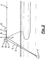
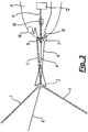
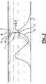
- FIG. 1 there is shown a group of catenary mooring lines 1 rising from seabed anchors to a hollow swivel connector assembly 2 with each line being partially supported by a subsea buoy 3.
- the hollow swivel connector assembly is in turn attached by the upper mooring line 4 to the bow of the vessel 5.
- a flexible fluid transfer riser 6 in Wave configuration ascending from the seabed to the hollow swivel connector assembly 2 and thence to a Quick Connect and Dis-Connect (QCDC) hangoff 7 close to the vessel prow.
- QCDC Quick Connect and Dis-Connect
- FIG. 2 there is shown in greater detail the upper mooring line 4 attached to a chafe chain 8 which passes through the panama fairlead 9 and bowstopper 10 to connect to the pickup line 11 deployed from the pickup winch 12.
- the QCDC is shown in greater detail divided into its components, viz. the upper QCDC assembly 7a, which is securely fixed to the vessel, the lower QCDC assembly 7b, which in the operational condition is held in the jaws of the upper QCDC assembly 7a, and the in-line fluid swivel 7c, which is fixed to the lower QCDC assembly 7b above it and to the head of the riser 6 below it.
- the upper QCDC assembly 7a and lower QCDC assembly 7b include hydraulically actuated anti-spill ball valves.
- FIG. 3 there is shown a plan view of the aforementioned features.
- ESV Emergency Shut-In Valve
- an abandonment buoy 14 Located on the focsle deck of the vessel during normal operation is an abandonment buoy 14 attached to the mooring pickup line at a point outboard of the panama fairlead.
- FIG. 4 there is shown the hollow swivel connector assembly in outside elevation and sagittal sections respectively.
- the outer cylinder 2a embraces the inner cylinder 2b, while end plates 2c retain the journal bearings within and assist in the transfer of axial load.
- the bridle of the upper mooring line 4 is attached to the torque bars 2d (as also visible in Figure 3 ).
- Figure 5 shows the water lubricated plastic journal bearings 2f between the inner and outer cylinders.
- the bearing may for example be an annular bearing, of the type supplied by Thordon Bearings Inc, although other bearing types may be used..
- the hollow swivel connector assembly is located at an intermediate depth between the sea surface and the seabed and consists of (a) an outer cylindrical sleeve, which may be made of steel, carrying padeyes for the connection of at least three mooring lines radiating therefrom, which mooring lines may be made of chain or of wire rope or of polymer rope or a hybrid of these and which terminate in seabed anchors, which may be drag embedment anchors or piled anchors or gravity anchors depending on the local geotechnical and metocean conditions, and (b) an inner cylindrical bush, which may be made of steel, which is located within the outer sleeve and can rotate within the sleeve with the aid of water-lubricated radial and axial plastic journal bearings and to which are affixed close to its upper end a pair of lever arms or torque bars connected to a pair of upper lines or to the bridle of a single line terminating in chafe chains passing through the panama fairlead(s) and secured by
- the fluid transfer riser ascending from the seabed passes through the hollow core of the inner cylinder, whose upper and lower lips are faired to match the Minimum Bending Radius (MBR) of the riser pipe, and proceeds thence to an in-line fluid swivel fixed to the lower part of a Quick Connect and Dis-Connect (QCDC) assembly mounted at and just forward of and/or just adjacent to the prow of the vessel.
- Flexible or rigid piping connects the upper QCDC assembly to the ship's manifold via an Emergency Shutdown Valve (ESV).
- ESV Emergency Shutdown Valve
- There may be more than one fluid riser in which case the fluid swivel will need to be a multi-path swivel of the toroidal or other suitable type depending on the fluid pressures involved.
- electrical power cables or electrical or fibre optic instrumentation and control cables in which case there will be a need for a slipring box mounted above or in place of the fluid swivel.
- the mooring lines below the hollow swivel connector assembly may be fitted with subsea buoys to improve the chain configuration and to reduce the pick up load when installing the mooring to the vessel. This may be particularly relevant in cases where the mooring lines are chains.
- the QCDC valves are shut and the QCDC jaws are opened thus dropping the head of the riser with the fluid swivel and lower QCDC assembly into the water, the riser sliding down through the core of the hollow swivel connector assembly until it rests on top of it.
- This descent is controlled, for example, by a double reeved tugger line passing through a block on the lower QCDC assembly.
- the tugger line end is released and the tugger line is run out of the block and recovered inboard.
- the lower QCDC assembly has a pennant and marker buoy attached for subsequent recovery and re-reeving of the tugger line upon return of the vessel.
- the abandonment buoy is now unlashed, the bowstopper is opened, and the pickup line is paid out by the pickup winch until the abandonment buoy has been pulled overboard and takes the weight of the mooring system.
- the pickup line which is now slack, is immediately disconnected and the vessel drifts back off the mooring before sailing away.
- the abandonment buoy may be designed to float on the sea surface or below the surface. In the latter case an additional pennant and marker buoy are needed and are located so as to minimise the risk of entanglement with the riser head pennant and marker.
- the disconnect method comprises first disconnecting the riser(s) and allowing them to free fall until restrained by a strop attached to the mooring chain. Subsequently the mooring is disconnected allowing it to free fall to the sea to be supported by an abandonment buoy. This release may be initiated by a single action on the vessel.
- FIG. 7 there is shown a general arrangement in elevation of the system after abandonment and vessel departure.
- an abandonment buoy 14 supporting the abandoned mooring system and a pennant 15 and marker buoy 16 to aid in its subsequent recovery.
- the lower QCDC assembly 7b and fluid swivel 7c which have descended with the riser head until they rest on the hollow swivel connector assembly 2 after the upper part of the fluid riser 6 has descended through the hollow swivel connector assembly and now hangs below it.
- a pennant 17 and marker buoy arrangement attached to the lower QCDC assembly 7b and having a length intended to minimise the risk of entanglement with the abandonment buoy pennant 15.
- the mooring pickup procedure on return of the vessel to the field is the reverse of the foregoing with the difference that the pennants have to be grappled from the focsle or recovered with the aid of a team deployed from the vessel in a rubber inflatable boat (RIB).
- RIB rubber inflatable boat
- the fluid transfer riser 6 is coupled to a Quick Connect and Disconnect (QCDC) hang-off mounted on a short cantilever frame close to the bow.
- QCDC Quick Connect and Disconnect
- FIG. 8 there is shown an isometric view of an attachment assembly according to an alternative embodiment of the invention, generally depicted at 80.
- This embodiment comprises a single chain stopper 81 from which a chafe chain 84 passes through a fairlead 82 at the bow 24 of the vessel 25 to the connector assembly 2.
- the fluid transfer riser 6 passes through the connector assembly 2 to an extended support means in the form of elongated chute 83.
- the elongated chute 83 is mounted on a frame 85 at the bow of the vessel and extends from the bow 24.
- the fluid transfer riser 6 passes over the chute 83 such that the upper position of the riser 6 is separated from the fairlead 82 and the hull of the vessel 25.
- the chute 83 therefore provides a cantilever structure which prevents the riser 6 from clashing with the vessel and provides separation between the path of the riser 6 and the chafe chain 84.
- FIG 9 is an isometric view of an alternative embodiment of the invention, comprising an attachment assembly generally shown at 90, which is similar to the assembly 80 and will be understood from Figure 8 and the accompanying description.
- the assembly 90 differs from that of 80 in that the connector assembly 2' is attached to the vessel by twin chain stoppers 91.
- the pair of chafe chains 94 pass through a pair of fairleads 92 at the bow 34 of the vessel 35, and as with the assembly 80, the riser 6 passes over an elongated chute 93 on a frame 95.
- the chute 93 provides an extended support means which separates the riser from the bow 34 of the vessel 35 and the path of the chafe chains 94.
- FIG 10 is an isometric view of a further alternative embodiment of the invention, generally shown at 100.
- the assembly 100 comprises a cantilever frame 105 which extends over the focsle deck equipment on the vessel 45.
- the cantilever frame 105 provides a short cantilever for hang-off of the chafe chains 104 coupled to the connector assembly 42.
- the cantilever frame 105 also supports an elongated chute 103 which extends over the frame 105 and provides a longer cantilever for the riser 46 which separates the riser position from the bow 44 of the vessel 45 and the chafe chains 104.
- the riser 46 comprises a pair of riser conduits
- the connector assembly 42 comprises multiple (in this case five) catenary mooring lines 47 to seabed anchors.
- FIG. 11 A further alternative attachment assembly is shown in Figure 11 , generally depicted at 110.
- the attachment assembly 110 is similar to the assembly 100 and will be understood from Figure 10 and the accompanying description.
- a cantilever frame 115 extends around focsle equipment (as opposed to the assembly 100 in which the cantilever frame 105 is built up and extends over the focsle deck equipment).
- the cantilever frame 115 provides chain hang-off for a pair of chafe chains 114 and supports an extended riser cantilever chute 113 which separates the position of the riser 46 from the hull of the vessel 55 and the chafe chains 114.
- the connector assembly of the described embodiments of the invention is configured such that the riser is isolated from the node of the mooring system (i.e. the connector assembly).
- This facilitates the provision of an extended support means, such as the elongated chute described with reference to Figures 8 to 11 , to be provided for the riser.
- the extended support means for the riser is not required to withstand or support the full mooring loads of the vessel, as the connector isolates the riser from the mooring loads.
- the upper portion of the flexible riser can be readily separated from the bow of the vessel and/or the chafe chains, for example by a simple elongated chute as illustrated in the embodiments of Figures 8 to 11 , which need only support the loads associated with the flexible riser itself.
- the invention provides a connector assembly for a vessel mooring system.
- the connector assembly has a first portion configured to be coupled to one or more mooring lines, and a second portion configured to be coupled to a vessel.
- the first and second portions are rotatable with respect to one another to permit a vessel coupling on the second portion to swivel about the mooring coupling on the first portion.
- the connector assembly comprises a guide for a conduit, which may be a fluid transfer conduit such as flexible riser.
- the invention also provides a vessel mooring system comprising the connector assembly and method of use.
- the present invention relates to a hollow swivel connector assembly for connecting a vessel to a mooring array in an offshore environment, to a vessel attached to such a connector assembly, to an offshore vessel mooring system containing such a connector assembly, and to one or more fluid transfer risers or cables ascending from the seabed and passing loosely through the connector assembly and thence to the focsle of the vessel via a fluid swivel and/or slipring box.
- the present invention creates an improved arrangement for mooring a tanker at an offshore location and transferring oil or other fluids between a submarine pipeline and the tanker in a manner which enables the tanker to weathervane unrestrictedly in response to changing weather and tidal flow directions.
- the arrangement eliminates the need for any significant invasion of the tanker hull or deck so that a vessel of opportunity can be employed and can be returned to ordinary ocean trading at the end of the project period.
- Embodiments of the invention permit rapid connection of the tanker to the mooring and riser and rapid disconnection.
- the system can be configured using components which are standard marine or offshore oil and gas industry items which are readily available for purchase or rental in the market.
- the novel custom-built hollow swivel connector assembly joins the upper and lower parts of the mooring line array and the fluid transfer riser ascends through the connector assembly on its way from the seabed to the prow of the vessel.
- a connector assembly which functions as a mooring swivel at the node, which is designed in such a way as to allow the riser(s) to pass through its centre, provides the mooring system with unlimited weathervaning capability.
- a preferred embodiment features a geo-stationary outer cylinder connected to the main mooring lines and an inner cylinder connected by one or more upper mooring lines to the vessel with which it is free to weathervane.
- the two cylinders are separated by water-lubricated plastic journal bearings of a type already widely used in naval, maritime, and offshore industry applications.
- the system may be used with a plurality of risers.
- the foregoing embodiments relate to vessel mooring systems, but it will be appreciated that the present invention also has application to the mooring of other types of offshore asset including drilling rigs and platforms and offshore energy generator devices.
- the connector assembly is used in to moor an offshore wave generator device, where a power transmission conduit is guided through the connector assembly.
Claims (15)
- Ensemble de connecteur (2) pour un système d'amarrage d'un navire, l'ensemble de connecteur comprenant :une première partie (2a) comprenant un accouplement d'amarrage, la première partie étant configurée pour être couplée à une ou plusieurs amarres (1) ;une deuxième partie (2b) comprenant un accouplement pour navire (4), la deuxième partie étant configurée pour être couplée à un navire, les première et deuxième parties pouvant tourner l'une par rapport à l'autre afin de permettre à l'accouplement pour navire sur la deuxième partie de pivoter autour de l'accouplement d'amarrage sur la première partie, et la deuxième partie étant disposée de façon à se trouver au moins partiellement au sein de la première partie ;un conduit de transfert de fluide (6) ; etun guide (2e) pour conduit de transfert de fluide, caractérisé en ce que le guide comprend une ouverture
dans la deuxième partie, à travers laquelle passe le conduit de transfert de fluide ;l'ouverture étant dotée de rebords incurvés supérieurs et inférieurs facilitant le passage du conduit de transfert de fluide dans l'ouverture, la forme des rebords supérieurs et inférieurs étant sélectionnée de sorte qu'elle corresponde à un rayon de courbure minimale du conduit de transfert de fluide. - Ensemble de connecteur selon la revendication 1, la deuxième partie (2b) étant disposée substantiellement au sein de la première partie (2a).
- Ensemble de connecteur selon une quelconque des revendications précédentes, le conduit de transfert de fluide (6) pouvant être déplacé dans une direction axiale relativement à l'ensemble de connecteur (2).
- Ensemble de connecteur selon une quelconque des revendications précédentes, le conduit de transfert de fluide (6) pouvant être déplacé par rotation relativement à l'ensemble de connecteur (2).
- Ensemble de connecteur selon une quelconque des revendications précédentes, l'ouverture comprenant un insert dont la forme est sélectionnée de façon qu'elle corresponde au rayon de courbure minimum du conduit de transfert de fluide (6).
- Ensemble de connecteur selon une quelconque des revendications précédentes, les première (2a) et deuxième (2b) parties comprenant des gaines internes et externes pouvant tourner l'une relativement à l'autre.
- Ensemble de connecteur selon une quelconque des revendications précédentes, la première partie (2a) comprenant une pluralité d'accouplements d'amarrage pour une pluralité d'amarres (1).
- Ensemble de connecteur selon une quelconque des revendications précédentes, la deuxième partie (2b) comprenant un manchon cylindrique interne.
- Ensemble de connecteur selon une quelconque des revendications précédentes, la deuxième partie (2b) comprenant une paire de leviers constituant l'au moins un accouplement pour navire.
- Ensemble de connecteur selon une quelconque des revendications précédentes, comprenant en outre des roulements entre les première (2a) et deuxième (2b) parties.
- Ensemble de connecteur selon la revendication 10, les roulements étant des roulements lubrifiés par l'eau.
- Ensemble de connecteur selon une quelconque des revendications précédentes, comprenant en outre un support allongé pour le conduit de transfert de fluide (6), fonctionnant pour séparer au moins une partie supérieure du conduit de transfert de fluide d'une partie de l'une ou plusieurs amarres (1).
- Ensemble de connecteur selon la revendication 12, le support allongé comprenant une structure en porte-à-faux.
- Ensemble de connecteur selon la revendication 12 ou 13, le support allongé comprenant une gouttière allongée pour le conduit de transfert de fluide (6).
- Ensemble de connecteur selon une quelconque des revendications 12 à 14, le support allongé étant isolé des charges d'amarrage sur l'ensemble de connecteur.
Applications Claiming Priority (2)
| Application Number | Priority Date | Filing Date | Title |
|---|---|---|---|
| GBGB1114291.6A GB201114291D0 (en) | 2011-08-19 | 2011-08-19 | Mooring system |
| PCT/GB2012/052023 WO2013027036A1 (fr) | 2011-08-19 | 2012-08-17 | Système d'amarrage et ensemble raccord |
Publications (3)
| Publication Number | Publication Date |
|---|---|
| EP2744703A1 EP2744703A1 (fr) | 2014-06-25 |
| EP2744703B1 true EP2744703B1 (fr) | 2017-10-11 |
| EP2744703B8 EP2744703B8 (fr) | 2017-11-29 |
Family
ID=44800540
Family Applications (1)
| Application Number | Title | Priority Date | Filing Date |
|---|---|---|---|
| EP12766125.4A Active EP2744703B8 (fr) | 2011-08-19 | 2012-08-17 | Système et connecteur d'amarrage |
Country Status (13)
| Country | Link |
|---|---|
| US (1) | US9032892B2 (fr) |
| EP (1) | EP2744703B8 (fr) |
| CN (1) | CN103874627B (fr) |
| AU (1) | AU2012298371B2 (fr) |
| BR (1) | BR112014003891B1 (fr) |
| CA (1) | CA2845797A1 (fr) |
| DK (1) | DK2744703T3 (fr) |
| GB (2) | GB201114291D0 (fr) |
| MX (1) | MX340002B (fr) |
| MY (1) | MY166156A (fr) |
| NO (1) | NO2744703T3 (fr) |
| TN (1) | TN2014000073A1 (fr) |
| WO (1) | WO2013027036A1 (fr) |
Families Citing this family (13)
| Publication number | Priority date | Publication date | Assignee | Title |
|---|---|---|---|---|
| CN114962165A (zh) * | 2014-02-06 | 2022-08-30 | 缅因大学系统委员会 | 组装漂浮式风力涡轮机平台的方法 |
| NO20141038A1 (no) * | 2014-08-25 | 2015-11-16 | Abyssus Marine Services As | Svivel for en fortøyningsline |
| KR101732374B1 (ko) * | 2015-10-21 | 2017-05-04 | 삼성중공업 주식회사 | 해상구조물 견인로프의 스윙방지 장치 |
| US10384364B2 (en) | 2017-02-07 | 2019-08-20 | Lamb Weston, Inc. | Water bearing and food cutting assembly |
| US10363679B2 (en) | 2017-02-07 | 2019-07-30 | Lamb Weston, Inc. | Water bearing and food cutting assembly |
| CN108995768A (zh) * | 2018-07-10 | 2018-12-14 | 浙江海洋大学 | 一种便于组装的海洋浮标 |
| GB2582576B (en) * | 2019-03-25 | 2021-09-29 | Acergy France SAS | Pressure-resistant buoys |
| CN110616674B (zh) * | 2019-11-15 | 2021-04-27 | 南京浦口科创投资集团有限公司 | 一种运输货船短暂休整船岸连接器 |
| DK180821B1 (en) * | 2019-11-25 | 2022-04-28 | Stillstrom As | A mooring buoy, a power system for an offshore vessel and a method of mooring a vessel |
| CN111140440A (zh) * | 2020-01-15 | 2020-05-12 | 上海电气风电集团股份有限公司 | 一种半潜漂浮式风机基础及风机 |
| CN111577551A (zh) * | 2020-05-27 | 2020-08-25 | 上海电气风电集团股份有限公司 | 一种漂浮式风机基础 |
| CN113911264B (zh) * | 2021-11-25 | 2022-11-01 | 江苏航运职业技术学院 | 一种运用于船舶的锚固固定支架及使用方法 |
| CN116661071B (zh) * | 2023-07-20 | 2023-12-01 | 绵阳华岩电子有限公司 | 一种角度可调的圆形连接器 |
Family Cites Families (23)
| Publication number | Priority date | Publication date | Assignee | Title |
|---|---|---|---|---|
| US3979785A (en) | 1974-08-09 | 1976-09-14 | Exxon Research And Engineering Company | Combined catenary and single anchor leg mooring system |
| US4154541A (en) * | 1977-06-13 | 1979-05-15 | Ricoh Company, Ltd. | Printer head assembly |
| FR2442759A1 (fr) | 1978-11-14 | 1980-06-27 | Inst Francais Du Petrole | Dispositif d'amarrage d'une installation flottante a une installation marine ancree |
| US4501113A (en) * | 1981-06-09 | 1985-02-26 | Gerber Curtis E | Fruit harvesting machine |
| NL8302203A (nl) * | 1983-06-21 | 1985-01-16 | Single Buoy Moorings | Afmeerboei. |
| GB9008675D0 (en) | 1990-04-18 | 1990-06-13 | Earl & Wright Ltd | Loading system |
| GB2273087B (en) | 1992-12-04 | 1996-05-29 | Gec Alsthom Ltd | Mooring systems |
| US5363789A (en) | 1993-09-15 | 1994-11-15 | Single Buoy Moorings Inc. | Disconnectable mooring system |
| US5381750A (en) | 1993-12-02 | 1995-01-17 | Imodco, Inc. | Vessel turret mooring system |
| AU7813194A (en) | 1994-10-07 | 1996-05-02 | Single Buoy Moorings Inc. | Submerged calm buoy |
| GB2296904B (en) | 1995-03-03 | 1996-12-18 | Victoria Oilfield Dev | Mooring and Flowline System |
| US5944448A (en) | 1996-12-18 | 1999-08-31 | Brovig Offshore Asa | Oil field installation with mooring and flowline system |
| NO311417B1 (no) | 1999-03-04 | 2001-11-26 | Advanced Prod & Loading As | System for forankring av et fartöy |
| US6126501A (en) * | 1999-09-15 | 2000-10-03 | Nortrans Offshore(S) Pte Ltd | Mooring system for tanker vessels |
| GB0002703D0 (en) | 2000-02-08 | 2000-03-29 | Victoria Oilfield Dev Limited | Mooring and flowline system |
| US6415828B1 (en) | 2000-07-27 | 2002-07-09 | Fmc Technologies, Inc. | Dual buoy single point mooring and fluid transfer system |
| EP1311340A1 (fr) * | 2000-08-24 | 2003-05-21 | Hilutec Systemtechnik GmbH & Co. KG | Dispositif et procede de melange de constituants |
| NO20015440D0 (no) | 2001-11-07 | 2001-11-07 | Hitec Marine As | Turret for kopling av en böye til et fartöy |
| GB0421795D0 (en) * | 2004-10-01 | 2004-11-03 | Baross John S | Full weathervaning bow mooring and riser inboarding assembly |
| US20080282955A1 (en) * | 2007-05-16 | 2008-11-20 | Horton Technologies, Llc | Pull In - Pay Out Mooring System |
| US7993176B2 (en) | 2008-02-19 | 2011-08-09 | Seahorse Equipment Corp | Submersible mooring system |
| WO2011042535A1 (fr) | 2009-10-08 | 2011-04-14 | Single Buoy Moorings Inc. | Bouée calm |
| US8631964B1 (en) * | 2011-05-10 | 2014-01-21 | Koreann H. Rael | Hose holding container assembly |
-
2011
- 2011-08-19 GB GBGB1114291.6A patent/GB201114291D0/en not_active Ceased
-
2012
- 2012-08-17 BR BR112014003891-0A patent/BR112014003891B1/pt active IP Right Grant
- 2012-08-17 CA CA2845797A patent/CA2845797A1/fr not_active Abandoned
- 2012-08-17 CN CN201280040505.XA patent/CN103874627B/zh not_active Expired - Fee Related
- 2012-08-17 WO PCT/GB2012/052023 patent/WO2013027036A1/fr active Application Filing
- 2012-08-17 DK DK12766125.4T patent/DK2744703T3/da active
- 2012-08-17 AU AU2012298371A patent/AU2012298371B2/en active Active
- 2012-08-17 US US14/239,404 patent/US9032892B2/en not_active Expired - Fee Related
- 2012-08-17 MY MYPI2014000439A patent/MY166156A/en unknown
- 2012-08-17 NO NO12766125A patent/NO2744703T3/no unknown
- 2012-08-17 EP EP12766125.4A patent/EP2744703B8/fr active Active
- 2012-08-17 MX MX2014001947A patent/MX340002B/es active IP Right Grant
- 2012-08-17 GB GB1214747.6A patent/GB2493851B/en active Active
-
2014
- 2014-02-19 TN TNP2014000073A patent/TN2014000073A1/en unknown
Non-Patent Citations (1)
| Title |
|---|
| None * |
Also Published As
| Publication number | Publication date |
|---|---|
| AU2012298371A2 (en) | 2014-05-01 |
| GB201114291D0 (en) | 2011-10-05 |
| EP2744703A1 (fr) | 2014-06-25 |
| US20140190385A1 (en) | 2014-07-10 |
| BR112014003891B1 (pt) | 2021-11-09 |
| GB2493851A (en) | 2013-02-20 |
| GB201214747D0 (en) | 2012-10-03 |
| MX2014001947A (es) | 2014-04-30 |
| CN103874627B (zh) | 2017-07-04 |
| WO2013027036A1 (fr) | 2013-02-28 |
| EP2744703B8 (fr) | 2017-11-29 |
| CN103874627A (zh) | 2014-06-18 |
| AU2012298371B2 (en) | 2016-06-09 |
| MX340002B (es) | 2016-06-20 |
| CA2845797A1 (fr) | 2013-02-28 |
| MY166156A (en) | 2018-06-06 |
| GB2493851B (en) | 2014-04-09 |
| TN2014000073A1 (en) | 2015-07-01 |
| DK2744703T3 (da) | 2017-11-06 |
| NO2744703T3 (fr) | 2018-03-10 |
| AU2012298371A1 (en) | 2014-04-03 |
| BR112014003891A2 (pt) | 2017-03-14 |
| US9032892B2 (en) | 2015-05-19 |
Similar Documents
| Publication | Publication Date | Title |
|---|---|---|
| EP2744703B1 (fr) | Système et connecteur d'amarrage | |
| AU2005291043B2 (en) | Offshore vessel mooring and riser inboarding system | |
| JP5362819B2 (ja) | 回転可能なターンテーブルを備えた分離可能なタレット係留システム | |
| US6435124B1 (en) | Mooring and flowline system | |
| Rutkowski | A comparison between conventional buoy mooring CBM, single point mooring SPM and single anchor loading sal systems considering the hydro-meteorological condition limits for safe ship’s operation offshore | |
| US6485343B1 (en) | Dynamic positioning dock-loading buoy (DPDL-buoy) and method for use of such a DPDL-buoy | |
| US20160236756A1 (en) | Tandem and side-by-side mooring offlaoding systems and associated methods | |
| US11198490B2 (en) | Disconnectable spread mooring and riser tower system and method | |
| US8156884B2 (en) | Vessel mooring systems and methods | |
| EP2398695B1 (fr) | Système d'ancrage en eaux profondes et ultra-profondes | |
| CN108602548B (zh) | 纤细塔楼 | |
| Mace et al. | Disconnectable riser turret mooring system for Jabiru's tanker-based floating production system | |
| De Boom | The development of turret mooring systems for floating production units | |
| GB2459739A (en) | A counterbalanced cantilever connector assembly for a vessel | |
| WO2009156751A2 (fr) | Amarrage de vaisseaux en haute mer et chargement par tube goulotte |
Legal Events
| Date | Code | Title | Description |
|---|---|---|---|
| PUAI | Public reference made under article 153(3) epc to a published international application that has entered the european phase |
Free format text: ORIGINAL CODE: 0009012 |
|
| 17P | Request for examination filed |
Effective date: 20140319 |
|
| AK | Designated contracting states |
Kind code of ref document: A1 Designated state(s): AL AT BE BG CH CY CZ DE DK EE ES FI FR GB GR HR HU IE IS IT LI LT LU LV MC MK MT NL NO PL PT RO RS SE SI SK SM TR |
|
| DAX | Request for extension of the european patent (deleted) | ||
| GRAP | Despatch of communication of intention to grant a patent |
Free format text: ORIGINAL CODE: EPIDOSNIGR1 |
|
| INTG | Intention to grant announced |
Effective date: 20170127 |
|
| GRAJ | Information related to disapproval of communication of intention to grant by the applicant or resumption of examination proceedings by the epo deleted |
Free format text: ORIGINAL CODE: EPIDOSDIGR1 |
|
| GRAP | Despatch of communication of intention to grant a patent |
Free format text: ORIGINAL CODE: EPIDOSNIGR1 |
|
| INTC | Intention to grant announced (deleted) | ||
| INTG | Intention to grant announced |
Effective date: 20170705 |
|
| GRAS | Grant fee paid |
Free format text: ORIGINAL CODE: EPIDOSNIGR3 |
|
| GRAA | (expected) grant |
Free format text: ORIGINAL CODE: 0009210 |
|
| AK | Designated contracting states |
Kind code of ref document: B1 Designated state(s): AL AT BE BG CH CY CZ DE DK EE ES FI FR GB GR HR HU IE IS IT LI LT LU LV MC MK MT NL NO PL PT RO RS SE SI SK SM TR |
|
| REG | Reference to a national code |
Ref country code: GB Ref legal event code: FG4D |
|
| REG | Reference to a national code |
Ref country code: CH Ref legal event code: EP |
|
| REG | Reference to a national code |
Ref country code: IE Ref legal event code: FG4D |
|
| REG | Reference to a national code |
Ref country code: DK Ref legal event code: T3 Effective date: 20171102 |
|
| REG | Reference to a national code |
Ref country code: SE Ref legal event code: TRGR |
|
| REG | Reference to a national code |
Ref country code: AT Ref legal event code: REF Ref document number: 935766 Country of ref document: AT Kind code of ref document: T Effective date: 20171115 |
|
| REG | Reference to a national code |
Ref country code: DE Ref legal event code: R096 Ref document number: 602012038430 Country of ref document: DE |
|
| RBV | Designated contracting states (corrected) |
Designated state(s): AL AT BE BG CH CY CZ DE DK EE ES FI FR GR HR HU IE IS IT LI LT LU LV MC MK MT NL NO PL PT RO RS SE SI SK SM TR |
|
| REG | Reference to a national code |
Ref country code: NO Ref legal event code: T2 Effective date: 20171011 |
|
| REG | Reference to a national code |
Ref country code: NL Ref legal event code: MP Effective date: 20171011 |
|
| REG | Reference to a national code |
Ref country code: LT Ref legal event code: MG4D |
|
| REG | Reference to a national code |
Ref country code: AT Ref legal event code: MK05 Ref document number: 935766 Country of ref document: AT Kind code of ref document: T Effective date: 20171011 |
|
| PG25 | Lapsed in a contracting state [announced via postgrant information from national office to epo] |
Ref country code: NL Free format text: LAPSE BECAUSE OF FAILURE TO SUBMIT A TRANSLATION OF THE DESCRIPTION OR TO PAY THE FEE WITHIN THE PRESCRIBED TIME-LIMIT Effective date: 20171011 |
|
| PG25 | Lapsed in a contracting state [announced via postgrant information from national office to epo] |
Ref country code: FI Free format text: LAPSE BECAUSE OF FAILURE TO SUBMIT A TRANSLATION OF THE DESCRIPTION OR TO PAY THE FEE WITHIN THE PRESCRIBED TIME-LIMIT Effective date: 20171011 Ref country code: ES Free format text: LAPSE BECAUSE OF FAILURE TO SUBMIT A TRANSLATION OF THE DESCRIPTION OR TO PAY THE FEE WITHIN THE PRESCRIBED TIME-LIMIT Effective date: 20171011 Ref country code: LT Free format text: LAPSE BECAUSE OF FAILURE TO SUBMIT A TRANSLATION OF THE DESCRIPTION OR TO PAY THE FEE WITHIN THE PRESCRIBED TIME-LIMIT Effective date: 20171011 |
|
| PG25 | Lapsed in a contracting state [announced via postgrant information from national office to epo] |
Ref country code: BG Free format text: LAPSE BECAUSE OF FAILURE TO SUBMIT A TRANSLATION OF THE DESCRIPTION OR TO PAY THE FEE WITHIN THE PRESCRIBED TIME-LIMIT Effective date: 20180111 Ref country code: RS Free format text: LAPSE BECAUSE OF FAILURE TO SUBMIT A TRANSLATION OF THE DESCRIPTION OR TO PAY THE FEE WITHIN THE PRESCRIBED TIME-LIMIT Effective date: 20171011 Ref country code: GR Free format text: LAPSE BECAUSE OF FAILURE TO SUBMIT A TRANSLATION OF THE DESCRIPTION OR TO PAY THE FEE WITHIN THE PRESCRIBED TIME-LIMIT Effective date: 20180112 Ref country code: HR Free format text: LAPSE BECAUSE OF FAILURE TO SUBMIT A TRANSLATION OF THE DESCRIPTION OR TO PAY THE FEE WITHIN THE PRESCRIBED TIME-LIMIT Effective date: 20171011 Ref country code: LV Free format text: LAPSE BECAUSE OF FAILURE TO SUBMIT A TRANSLATION OF THE DESCRIPTION OR TO PAY THE FEE WITHIN THE PRESCRIBED TIME-LIMIT Effective date: 20171011 Ref country code: AT Free format text: LAPSE BECAUSE OF FAILURE TO SUBMIT A TRANSLATION OF THE DESCRIPTION OR TO PAY THE FEE WITHIN THE PRESCRIBED TIME-LIMIT Effective date: 20171011 |
|
| REG | Reference to a national code |
Ref country code: DE Ref legal event code: R097 Ref document number: 602012038430 Country of ref document: DE |
|
| PG25 | Lapsed in a contracting state [announced via postgrant information from national office to epo] |
Ref country code: EE Free format text: LAPSE BECAUSE OF FAILURE TO SUBMIT A TRANSLATION OF THE DESCRIPTION OR TO PAY THE FEE WITHIN THE PRESCRIBED TIME-LIMIT Effective date: 20171011 Ref country code: SK Free format text: LAPSE BECAUSE OF FAILURE TO SUBMIT A TRANSLATION OF THE DESCRIPTION OR TO PAY THE FEE WITHIN THE PRESCRIBED TIME-LIMIT Effective date: 20171011 Ref country code: CZ Free format text: LAPSE BECAUSE OF FAILURE TO SUBMIT A TRANSLATION OF THE DESCRIPTION OR TO PAY THE FEE WITHIN THE PRESCRIBED TIME-LIMIT Effective date: 20171011 |
|
| PLBE | No opposition filed within time limit |
Free format text: ORIGINAL CODE: 0009261 |
|
| STAA | Information on the status of an ep patent application or granted ep patent |
Free format text: STATUS: NO OPPOSITION FILED WITHIN TIME LIMIT |
|
| PG25 | Lapsed in a contracting state [announced via postgrant information from national office to epo] |
Ref country code: IT Free format text: LAPSE BECAUSE OF FAILURE TO SUBMIT A TRANSLATION OF THE DESCRIPTION OR TO PAY THE FEE WITHIN THE PRESCRIBED TIME-LIMIT Effective date: 20171011 Ref country code: RO Free format text: LAPSE BECAUSE OF FAILURE TO SUBMIT A TRANSLATION OF THE DESCRIPTION OR TO PAY THE FEE WITHIN THE PRESCRIBED TIME-LIMIT Effective date: 20171011 Ref country code: SM Free format text: LAPSE BECAUSE OF FAILURE TO SUBMIT A TRANSLATION OF THE DESCRIPTION OR TO PAY THE FEE WITHIN THE PRESCRIBED TIME-LIMIT Effective date: 20171011 Ref country code: PL Free format text: LAPSE BECAUSE OF FAILURE TO SUBMIT A TRANSLATION OF THE DESCRIPTION OR TO PAY THE FEE WITHIN THE PRESCRIBED TIME-LIMIT Effective date: 20171011 |
|
| 26N | No opposition filed |
Effective date: 20180712 |
|
| PG25 | Lapsed in a contracting state [announced via postgrant information from national office to epo] |
Ref country code: SI Free format text: LAPSE BECAUSE OF FAILURE TO SUBMIT A TRANSLATION OF THE DESCRIPTION OR TO PAY THE FEE WITHIN THE PRESCRIBED TIME-LIMIT Effective date: 20171011 |
|
| REG | Reference to a national code |
Ref country code: DE Ref legal event code: R119 Ref document number: 602012038430 Country of ref document: DE |
|
| REG | Reference to a national code |
Ref country code: DK Ref legal event code: EBP Effective date: 20180831 |
|
| PG25 | Lapsed in a contracting state [announced via postgrant information from national office to epo] |
Ref country code: MC Free format text: LAPSE BECAUSE OF FAILURE TO SUBMIT A TRANSLATION OF THE DESCRIPTION OR TO PAY THE FEE WITHIN THE PRESCRIBED TIME-LIMIT Effective date: 20171011 |
|
| REG | Reference to a national code |
Ref country code: CH Ref legal event code: PL |
|
| REG | Reference to a national code |
Ref country code: SE Ref legal event code: EUG |
|
| PG25 | Lapsed in a contracting state [announced via postgrant information from national office to epo] |
Ref country code: CH Free format text: LAPSE BECAUSE OF NON-PAYMENT OF DUE FEES Effective date: 20180831 Ref country code: IS Free format text: LAPSE BECAUSE OF FAILURE TO SUBMIT A TRANSLATION OF THE DESCRIPTION OR TO PAY THE FEE WITHIN THE PRESCRIBED TIME-LIMIT Effective date: 20190301 Ref country code: LI Free format text: LAPSE BECAUSE OF NON-PAYMENT OF DUE FEES Effective date: 20180831 Ref country code: LU Free format text: LAPSE BECAUSE OF NON-PAYMENT OF DUE FEES Effective date: 20180817 |
|
| REG | Reference to a national code |
Ref country code: BE Ref legal event code: MM Effective date: 20180831 |
|
| PG25 | Lapsed in a contracting state [announced via postgrant information from national office to epo] |
Ref country code: SE Free format text: LAPSE BECAUSE OF NON-PAYMENT OF DUE FEES Effective date: 20180818 |
|
| PG25 | Lapsed in a contracting state [announced via postgrant information from national office to epo] |
Ref country code: DE Free format text: LAPSE BECAUSE OF NON-PAYMENT OF DUE FEES Effective date: 20190301 Ref country code: DK Free format text: LAPSE BECAUSE OF NON-PAYMENT OF DUE FEES Effective date: 20180831 |
|
| PG25 | Lapsed in a contracting state [announced via postgrant information from national office to epo] |
Ref country code: FR Free format text: LAPSE BECAUSE OF NON-PAYMENT OF DUE FEES Effective date: 20180831 Ref country code: BE Free format text: LAPSE BECAUSE OF NON-PAYMENT OF DUE FEES Effective date: 20180831 |
|
| PG25 | Lapsed in a contracting state [announced via postgrant information from national office to epo] |
Ref country code: MT Free format text: LAPSE BECAUSE OF NON-PAYMENT OF DUE FEES Effective date: 20180817 |
|
| PG25 | Lapsed in a contracting state [announced via postgrant information from national office to epo] |
Ref country code: TR Free format text: LAPSE BECAUSE OF FAILURE TO SUBMIT A TRANSLATION OF THE DESCRIPTION OR TO PAY THE FEE WITHIN THE PRESCRIBED TIME-LIMIT Effective date: 20171011 |
|
| PG25 | Lapsed in a contracting state [announced via postgrant information from national office to epo] |
Ref country code: PT Free format text: LAPSE BECAUSE OF FAILURE TO SUBMIT A TRANSLATION OF THE DESCRIPTION OR TO PAY THE FEE WITHIN THE PRESCRIBED TIME-LIMIT Effective date: 20171011 Ref country code: HU Free format text: LAPSE BECAUSE OF FAILURE TO SUBMIT A TRANSLATION OF THE DESCRIPTION OR TO PAY THE FEE WITHIN THE PRESCRIBED TIME-LIMIT; INVALID AB INITIO Effective date: 20120817 |
|
| PG25 | Lapsed in a contracting state [announced via postgrant information from national office to epo] |
Ref country code: MK Free format text: LAPSE BECAUSE OF NON-PAYMENT OF DUE FEES Effective date: 20171011 Ref country code: CY Free format text: LAPSE BECAUSE OF FAILURE TO SUBMIT A TRANSLATION OF THE DESCRIPTION OR TO PAY THE FEE WITHIN THE PRESCRIBED TIME-LIMIT Effective date: 20171011 |
|
| PG25 | Lapsed in a contracting state [announced via postgrant information from national office to epo] |
Ref country code: AL Free format text: LAPSE BECAUSE OF FAILURE TO SUBMIT A TRANSLATION OF THE DESCRIPTION OR TO PAY THE FEE WITHIN THE PRESCRIBED TIME-LIMIT Effective date: 20171011 |
|
| PGFP | Annual fee paid to national office [announced via postgrant information from national office to epo] |
Ref country code: NO Payment date: 20230824 Year of fee payment: 12 Ref country code: IE Payment date: 20230822 Year of fee payment: 12 |