EP2744589B1 - Method and device for cleaning exhaust gases by way of fluidized bed reactors - Google Patents
Method and device for cleaning exhaust gases by way of fluidized bed reactors Download PDFInfo
- Publication number
- EP2744589B1 EP2744589B1 EP12726626.0A EP12726626A EP2744589B1 EP 2744589 B1 EP2744589 B1 EP 2744589B1 EP 12726626 A EP12726626 A EP 12726626A EP 2744589 B1 EP2744589 B1 EP 2744589B1
- Authority
- EP
- European Patent Office
- Prior art keywords
- gas
- fluidized bed
- bed reactor
- nozzles
- solids
- Prior art date
- Legal status (The legal status is an assumption and is not a legal conclusion. Google has not performed a legal analysis and makes no representation as to the accuracy of the status listed.)
- Active
Links
- 239000007789 gas Substances 0.000 title claims description 112
- 238000000034 method Methods 0.000 title claims description 33
- 238000004140 cleaning Methods 0.000 title claims description 4
- 239000007787 solid Substances 0.000 claims description 47
- 239000002594 sorbent Substances 0.000 claims description 28
- 238000006243 chemical reaction Methods 0.000 claims description 14
- XLYOFNOQVPJJNP-UHFFFAOYSA-N water Substances O XLYOFNOQVPJJNP-UHFFFAOYSA-N 0.000 claims description 14
- 239000002245 particle Substances 0.000 claims description 9
- 239000007795 chemical reaction product Substances 0.000 claims description 7
- 239000006096 absorbing agent Substances 0.000 claims description 6
- 238000002347 injection Methods 0.000 claims description 6
- 239000007924 injection Substances 0.000 claims description 6
- 238000009434 installation Methods 0.000 claims description 5
- 230000002378 acidificating effect Effects 0.000 claims description 3
- 238000001816 cooling Methods 0.000 claims description 3
- 239000010881 fly ash Substances 0.000 claims description 3
- 239000008247 solid mixture Substances 0.000 claims description 2
- 239000003546 flue gas Substances 0.000 description 20
- UGFAIRIUMAVXCW-UHFFFAOYSA-N Carbon monoxide Chemical compound [O+]#[C-] UGFAIRIUMAVXCW-UHFFFAOYSA-N 0.000 description 16
- 238000002485 combustion reaction Methods 0.000 description 5
- 239000000428 dust Substances 0.000 description 5
- RAHZWNYVWXNFOC-UHFFFAOYSA-N Sulphur dioxide Chemical compound O=S=O RAHZWNYVWXNFOC-UHFFFAOYSA-N 0.000 description 4
- 239000003153 chemical reaction reagent Substances 0.000 description 4
- 239000000463 material Substances 0.000 description 4
- 238000010521 absorption reaction Methods 0.000 description 3
- 230000015572 biosynthetic process Effects 0.000 description 3
- 238000009833 condensation Methods 0.000 description 3
- 230000005494 condensation Effects 0.000 description 3
- 238000006477 desulfuration reaction Methods 0.000 description 3
- 230000023556 desulfurization Effects 0.000 description 3
- 239000003344 environmental pollutant Substances 0.000 description 3
- 239000012530 fluid Substances 0.000 description 3
- 238000002156 mixing Methods 0.000 description 3
- 231100000719 pollutant Toxicity 0.000 description 3
- 238000000746 purification Methods 0.000 description 3
- 239000007921 spray Substances 0.000 description 3
- 230000001133 acceleration Effects 0.000 description 2
- 239000011575 calcium Substances 0.000 description 2
- AXCZMVOFGPJBDE-UHFFFAOYSA-L calcium dihydroxide Chemical compound [OH-].[OH-].[Ca+2] AXCZMVOFGPJBDE-UHFFFAOYSA-L 0.000 description 2
- 239000000920 calcium hydroxide Substances 0.000 description 2
- 229910001861 calcium hydroxide Inorganic materials 0.000 description 2
- 235000011116 calcium hydroxide Nutrition 0.000 description 2
- 239000000567 combustion gas Substances 0.000 description 2
- 239000002131 composite material Substances 0.000 description 2
- 238000010586 diagram Methods 0.000 description 2
- 238000011068 loading method Methods 0.000 description 2
- 238000000465 moulding Methods 0.000 description 2
- 230000001473 noxious effect Effects 0.000 description 2
- 239000012429 reaction media Substances 0.000 description 2
- 238000000926 separation method Methods 0.000 description 2
- 238000003860 storage Methods 0.000 description 2
- 229910052815 sulfur oxide Inorganic materials 0.000 description 2
- OYPRJOBELJOOCE-UHFFFAOYSA-N Calcium Chemical compound [Ca] OYPRJOBELJOOCE-UHFFFAOYSA-N 0.000 description 1
- BVKZGUZCCUSVTD-UHFFFAOYSA-L Carbonate Chemical compound [O-]C([O-])=O BVKZGUZCCUSVTD-UHFFFAOYSA-L 0.000 description 1
- DGAQECJNVWCQMB-PUAWFVPOSA-M Ilexoside XXIX Chemical compound C[C@@H]1CC[C@@]2(CC[C@@]3(C(=CC[C@H]4[C@]3(CC[C@@H]5[C@@]4(CC[C@@H](C5(C)C)OS(=O)(=O)[O-])C)C)[C@@H]2[C@]1(C)O)C)C(=O)O[C@H]6[C@@H]([C@H]([C@@H]([C@H](O6)CO)O)O)O.[Na+] DGAQECJNVWCQMB-PUAWFVPOSA-M 0.000 description 1
- FYYHWMGAXLPEAU-UHFFFAOYSA-N Magnesium Chemical compound [Mg] FYYHWMGAXLPEAU-UHFFFAOYSA-N 0.000 description 1
- ZLMJMSJWJFRBEC-UHFFFAOYSA-N Potassium Chemical compound [K] ZLMJMSJWJFRBEC-UHFFFAOYSA-N 0.000 description 1
- 239000000443 aerosol Substances 0.000 description 1
- XAGFODPZIPBFFR-UHFFFAOYSA-N aluminium Chemical compound [Al] XAGFODPZIPBFFR-UHFFFAOYSA-N 0.000 description 1
- 229910052782 aluminium Inorganic materials 0.000 description 1
- 239000007864 aqueous solution Substances 0.000 description 1
- 239000007900 aqueous suspension Substances 0.000 description 1
- 229910052791 calcium Inorganic materials 0.000 description 1
- BRPQOXSCLDDYGP-UHFFFAOYSA-N calcium oxide Chemical compound [O-2].[Ca+2] BRPQOXSCLDDYGP-UHFFFAOYSA-N 0.000 description 1
- 239000000292 calcium oxide Substances 0.000 description 1
- ODINCKMPIJJUCX-UHFFFAOYSA-N calcium oxide Inorganic materials [Ca]=O ODINCKMPIJJUCX-UHFFFAOYSA-N 0.000 description 1
- 150000001768 cations Chemical class 0.000 description 1
- 239000003795 chemical substances by application Substances 0.000 description 1
- 239000011362 coarse particle Substances 0.000 description 1
- 238000004891 communication Methods 0.000 description 1
- 238000007334 copolymerization reaction Methods 0.000 description 1
- 230000008021 deposition Effects 0.000 description 1
- 238000005108 dry cleaning Methods 0.000 description 1
- 238000001035 drying Methods 0.000 description 1
- 238000005243 fluidization Methods 0.000 description 1
- 239000010795 gaseous waste Substances 0.000 description 1
- XLYOFNOQVPJJNP-UHFFFAOYSA-M hydroxide Chemical compound [OH-] XLYOFNOQVPJJNP-UHFFFAOYSA-M 0.000 description 1
- 239000012535 impurity Substances 0.000 description 1
- 239000007788 liquid Substances 0.000 description 1
- 239000011777 magnesium Substances 0.000 description 1
- 229910052749 magnesium Inorganic materials 0.000 description 1
- 238000004519 manufacturing process Methods 0.000 description 1
- 238000010310 metallurgical process Methods 0.000 description 1
- 239000000203 mixture Substances 0.000 description 1
- 239000013618 particulate matter Substances 0.000 description 1
- 230000035515 penetration Effects 0.000 description 1
- 230000002093 peripheral effect Effects 0.000 description 1
- 231100000614 poison Toxicity 0.000 description 1
- 238000006116 polymerization reaction Methods 0.000 description 1
- 239000011591 potassium Substances 0.000 description 1
- 229910052700 potassium Inorganic materials 0.000 description 1
- 239000000047 product Substances 0.000 description 1
- 239000000376 reactant Substances 0.000 description 1
- 230000003134 recirculating effect Effects 0.000 description 1
- 230000000630 rising effect Effects 0.000 description 1
- 238000004062 sedimentation Methods 0.000 description 1
- 238000007493 shaping process Methods 0.000 description 1
- 238000005245 sintering Methods 0.000 description 1
- 239000011734 sodium Substances 0.000 description 1
- 229910052708 sodium Inorganic materials 0.000 description 1
- 239000000126 substance Substances 0.000 description 1
- 239000002341 toxic gas Substances 0.000 description 1
- 239000003440 toxic substance Substances 0.000 description 1
- 238000009827 uniform distribution Methods 0.000 description 1
- 239000004711 α-olefin Substances 0.000 description 1
Images


Classifications
-
- B—PERFORMING OPERATIONS; TRANSPORTING
- B01—PHYSICAL OR CHEMICAL PROCESSES OR APPARATUS IN GENERAL
- B01D—SEPARATION
- B01D53/00—Separation of gases or vapours; Recovering vapours of volatile solvents from gases; Chemical or biological purification of waste gases, e.g. engine exhaust gases, smoke, fumes, flue gases, aerosols
- B01D53/34—Chemical or biological purification of waste gases
- B01D53/38—Removing components of undefined structure
- B01D53/40—Acidic components
-
- B—PERFORMING OPERATIONS; TRANSPORTING
- B01—PHYSICAL OR CHEMICAL PROCESSES OR APPARATUS IN GENERAL
- B01D—SEPARATION
- B01D53/00—Separation of gases or vapours; Recovering vapours of volatile solvents from gases; Chemical or biological purification of waste gases, e.g. engine exhaust gases, smoke, fumes, flue gases, aerosols
- B01D53/34—Chemical or biological purification of waste gases
- B01D53/46—Removing components of defined structure
- B01D53/48—Sulfur compounds
- B01D53/50—Sulfur oxides
- B01D53/508—Sulfur oxides by treating the gases with solids
-
- B—PERFORMING OPERATIONS; TRANSPORTING
- B01—PHYSICAL OR CHEMICAL PROCESSES OR APPARATUS IN GENERAL
- B01D—SEPARATION
- B01D53/00—Separation of gases or vapours; Recovering vapours of volatile solvents from gases; Chemical or biological purification of waste gases, e.g. engine exhaust gases, smoke, fumes, flue gases, aerosols
- B01D53/34—Chemical or biological purification of waste gases
- B01D53/46—Removing components of defined structure
- B01D53/68—Halogens or halogen compounds
- B01D53/685—Halogens or halogen compounds by treating the gases with solids
-
- B—PERFORMING OPERATIONS; TRANSPORTING
- B01—PHYSICAL OR CHEMICAL PROCESSES OR APPARATUS IN GENERAL
- B01D—SEPARATION
- B01D53/00—Separation of gases or vapours; Recovering vapours of volatile solvents from gases; Chemical or biological purification of waste gases, e.g. engine exhaust gases, smoke, fumes, flue gases, aerosols
- B01D53/34—Chemical or biological purification of waste gases
- B01D53/74—General processes for purification of waste gases; Apparatus or devices specially adapted therefor
- B01D53/75—Multi-step processes
-
- B—PERFORMING OPERATIONS; TRANSPORTING
- B01—PHYSICAL OR CHEMICAL PROCESSES OR APPARATUS IN GENERAL
- B01D—SEPARATION
- B01D53/00—Separation of gases or vapours; Recovering vapours of volatile solvents from gases; Chemical or biological purification of waste gases, e.g. engine exhaust gases, smoke, fumes, flue gases, aerosols
- B01D53/34—Chemical or biological purification of waste gases
- B01D53/74—General processes for purification of waste gases; Apparatus or devices specially adapted therefor
- B01D53/81—Solid phase processes
- B01D53/83—Solid phase processes with moving reactants
-
- B—PERFORMING OPERATIONS; TRANSPORTING
- B01—PHYSICAL OR CHEMICAL PROCESSES OR APPARATUS IN GENERAL
- B01D—SEPARATION
- B01D53/00—Separation of gases or vapours; Recovering vapours of volatile solvents from gases; Chemical or biological purification of waste gases, e.g. engine exhaust gases, smoke, fumes, flue gases, aerosols
- B01D53/34—Chemical or biological purification of waste gases
- B01D53/74—General processes for purification of waste gases; Apparatus or devices specially adapted therefor
- B01D53/86—Catalytic processes
- B01D53/88—Handling or mounting catalysts
- B01D53/885—Devices in general for catalytic purification of waste gases
-
- B—PERFORMING OPERATIONS; TRANSPORTING
- B01—PHYSICAL OR CHEMICAL PROCESSES OR APPARATUS IN GENERAL
- B01D—SEPARATION
- B01D2251/00—Reactants
- B01D2251/40—Alkaline earth metal or magnesium compounds
- B01D2251/404—Alkaline earth metal or magnesium compounds of calcium
-
- B—PERFORMING OPERATIONS; TRANSPORTING
- B01—PHYSICAL OR CHEMICAL PROCESSES OR APPARATUS IN GENERAL
- B01D—SEPARATION
- B01D2258/00—Sources of waste gases
- B01D2258/02—Other waste gases
- B01D2258/0283—Flue gases
Definitions
- the present invention relates to a method and apparatus for purifying exhaust gases using a circulating fluidized bed.
- Fluidized bed plants are also used according to the prior art for exhaust gas purification by the removal of noxious gases such as SOx and / or HCl and / or HF from flue gases.
- a flue gas is injected via a feed line in a fluidized bed reactor.
- a sorbent such as hydrated lime or calcium oxide is also injected into the fluidized bed reactor. Solid circulation of the solids deposited in a filter to the reactor produces a circulating fluidized bed in which the flue gas comes into contact with the sorbent and noxious gases are separated from the flue gas.
- the document EP2263780A1 describes a flue gas purification system with a fluidized bed reactor, which contains a flue gas inlet unit and a flue gas outlet unit, wherein the flue gas inlet unit is followed by a nozzle unit which is equipped with nozzles, and wherein the nozzles have a different cross section.
- the document US5238659A describes a reaction apparatus having a granular fluid bed dust removing apparatus using a granular reaction agent comprising a cylindrical airtight vessel containing a gas discharge port, a reagent supply port and a reagent storage section in the upper part of the cylindrical airtight vessel, further comprising a gas introduction port, a gas reaction chamber provided with the gas introduction port, and a gas reaction path formed in a middle part of the gas reaction chamber through gas introduction slots, wherein the gas reaction path is in open communication with the reagent storage section in the upper part of the cylindrical airtight vessel, thereby forming a standing column with the reaction medium, and a lower part with an adjustable outlet, the adjustable outlet controlling the speed of movement of the standing column of the reaction chamber It is determined by the gas flow during which the contaminating and toxic substances are absorbed from the upflowing gas stream and thereby removed.
- the direction of the nozzles can be changed such that when flowing through the gas through the nozzle, a rotation takes place along the flow axis.
- the rotation about the flow axis should not be so strong that a separation of the solids from the gas takes place as in a cyclone.
- the solids deposited in the filter are recycled to 0% to 99%, preferably to 20% to 99%, in the fluidized bed reactor.
- purified gas is to be understood as meaning purified crude gas (exhaust gas) that has passed through the fluidized-bed reactor at least once.
- the acidic components of the exhaust gas react in the expanded one so-called circulating fluidized bed to the solid reaction products, which together with the solids contained in the raw gas, such as fly ash, and the sorbent form the expanded fluidized bed.
- Solids can be fed back to the fluidized bed reactor via a line (6).
- a return of the sorbent via the line (6) is advantageous.
- the discharge of the reaction product takes place via the line (12).
- the exit cone is 10 ° from the vertical.
- Multiple nozzles end in the cone with the opening angle of 20 ° from the vertical. With an optimal configuration of the multiple nozzles all nozzles run at the same speed.
Description
Die vorliegende Erfindung betrifft ein Verfahren sowie eine Vorrichtung zur Reinigung von Abgasen unter Verwendung einer zirkulierenden Wirbelschicht.The present invention relates to a method and apparatus for purifying exhaust gases using a circulating fluidized bed.
Zirkulierende Wirbelschichten werden in unterschiedlichen technischen Prozessen eingesetzt, um Feststoffe mit Gasen, Flüssigkeiten oder anderen Feststoffen in engen Kontakt zu bringen.Circulating fluidized beds are used in various technical processes to bring solids into contact with gases, liquids or other solids.
Wirbelschichtanlagen werden nach dem Stand der Technik auch zur Abgasreinigung durch Abscheidung von Schadgasen wie SOx und/oder HCl und/oder HF aus Rauchgasen verwendet. In einer solchen Anlage nach dem Stand der Technik wird ein Rauchgas über eine Zuleitung in einen Wirbelschichtreaktor eingeblasen. Ein Sorbens, wie Kalkhydrat oder Kalziumoxid wird ebenfalls in den Wirbelschichtreaktor eingeblasen. Durch Feststoffzirkulation der in einem Filter abgeschiedenen Feststoffe zum Reaktor entsteht eine zirkulierende Wirbelschicht, in der das Rauchgas mit dem Sorbens in Berührung kommt und Schadgase aus dem Rauchgas abgeschieden werden.Fluidized bed plants are also used according to the prior art for exhaust gas purification by the removal of noxious gases such as SOx and / or HCl and / or HF from flue gases. In such a plant according to the prior art, a flue gas is injected via a feed line in a fluidized bed reactor. A sorbent such as hydrated lime or calcium oxide is also injected into the fluidized bed reactor. Solid circulation of the solids deposited in a filter to the reactor produces a circulating fluidized bed in which the flue gas comes into contact with the sorbent and noxious gases are separated from the flue gas.
Das Rauchgas wird mit den abgeschiedenen Reaktionsprodukten und dem Sorbens über eine Leitung aus dem Wirbelschichtreaktor geleitet und in einem nachgeschalteten Filtersystem mit Feststoffabscheider entstaubt. Das gereinigte Rauchgas kann dann entlassen werden. Ein Großteil des so abgeschiedenen Sorbens mit den Reaktionsprodukten kann wieder in den Wirbelschichtreaktor zurückgeführt werden.The flue gas is passed with the separated reaction products and the sorbent via a line from the fluidized bed reactor and dedusted in a downstream filter system with solids. The cleaned flue gas can then be released. A large part of the thus deposited sorbent with the reaction products can be recycled back to the fluidized bed reactor.
Vom Betrieb von Anlagen unter Verwendung einer zirkulierenden Wirbelschicht ist bekannt, dass sich speziell an der Innenfläche des Reaktorraumes Anbackungen, Gemische aus Wasser und Feinstaub, bilden. Bei Reinigungsverfahren unter Einsatz von Sprühwasser im Wirbelschichtreaktor bilden sich diese Anbackungen besonders am Düsenmund der Wasserdüsen. Die Anbackungen entstehen zumeist zeitlich und räumlich ungleichmäßig im Wirbelschichtreaktor, weshalb deren Entstehung nicht vorhersehbar ist.From the operation of plants using a circulating fluidized bed is known that form, especially on the inner surface of the reactor chamber caking, mixtures of water and particulate matter. In cleaning processes using spray water in a fluidized bed reactor, these caking forms especially at the nozzle mouth of the water nozzles. The caking usually arise temporally and spatially unevenly in the fluidized bed reactor, which is why their formation is not predictable.
Diese Anbackungen können zum Einen durch einen unzureichende Feststoffbeladung der Wirbelschicht durch eine unsachgemäße Ausbildung der Wasserdüsen, der Position der Wasserdüsen hinsichtlich des Umfanges des Reaktorraumes und/oder der Höhe des Reaktorraumes sowie der Eindringtiefe der Wasserdüsen in den Reaktorraum verursacht werden.These caking can on the one hand by an insufficient Solid loading of the fluidized bed caused by improper design of the water nozzles, the position of the water nozzles with respect to the circumference of the reactor space and / or the height of the reactor space and the penetration depth of the water nozzles in the reactor space.
Dadurch kann es zu einer Störung der gleichmäßigen Verteilung der rezirkulierenden Feststoffe und somit zu einer Verminderung des Stoffkontaktes und einer Reduktion der Schadgasabscheidung kommen. Diese Ansätze können nach unten fallen und dabei Düsen und Zufuhrleitungen des Reaktors verstopfen. Besonders bei zunehmender Größe der Anbackungen können diese zu erheblichen Störungen des Anlagenbetriebes führen.This can lead to a disturbance of the uniform distribution of the recirculating solids and thus to a reduction of the substance contact and a reduction of the noxious gas separation. These lumps may fall down, clogging nozzles and feed lines of the reactor. Especially with increasing size of the caking these can lead to significant disruption of plant operation.
In der
Das Dokument
Das Dokument
Das Dokument
Das Dokument
Das Dokument
Das Dokument
Das Dokument
Das Dokument
Das Dokument
Die Aufgabe der vorliegenden Erfindung war es, eine Möglichkeit zu finden, wodurch besagte Anbackungen in einem Wirbelschichtreaktor stark verringert bzw. vermieden werden können und somit den Stoff- und Wärmeaustausch während der Reaktion zu gewährleisten.The object of the present invention was to find a way whereby said caking in a fluidized bed reactor can be greatly reduced or avoided and thus to ensure the mass and heat exchange during the reaction.
Gelöst wird die Aufgabe durch das erfindungsgemäße Verfahren zur Reinigung von Abgasen, bei dem in einem Wirbelschichtreaktor ein Abgas mit einem festen Sorbens zusammengeführt wird, in einem nachfolgenden Filtersystem Feststoffe abgeschieden werden und anschließend das Sorbens bis zu 99 % dem Wirbelschichtreaktor wieder zugeführt wird, wobei das Gas eine Rotation um die Strömungsachse im Wirbelschichtreaktor erfährt.The object is achieved by the inventive method for purifying exhaust gases, in which in a fluidized bed reactor, an exhaust gas is combined with a solid sorbent, solids are deposited in a subsequent filter system and then the sorbent is fed to the fluidized bed reactor again up to 99%, the Gas undergoes a rotation about the flow axis in the fluidized bed reactor.
Die zirkulierende Wirbelschicht wird somit durch eine Rotationsbewegung längs der Strömungsachse des Gases, einschließlich der von ihr beförderten Feststoffe, überlagert. Dadurch wird eine gleichmäßige Abscheidung der Feststoffe an der Reaktorinnenwand bewirkt. Bereiche ohne Feststoffabsetzung werden somit verringert oder sogar gänzlich vermieden.The circulating fluidized bed is thus superimposed by a rotational movement along the flow axis of the gas, including the solids carried by it. As a result, a uniform deposition of the solids is effected on the reactor inner wall. Areas without sedimentation are thus reduced or even completely avoided.
Das erfindungsgemäße Verfahren ist bei trockenen und/oder halbtrockenen Reinigungsverfahren in einem Wirbelschichtreaktor anwendbar. Unter trockenen Reinigungsverfahren sind insbesondere Verfahren zu verstehen, wie sie beispielsweise in den Dokumenten
Unter "Abgase" im Sinne der vorliegenden Erfindung sind sämtliche gasförmige Abfallprodukte zu verstehen, die bei einem Stoffumwandlungsprozess anfallen. Dies umfasst Rauchgase aus Verbrennungsanlagen, Brandgase, Abgase aus Verbrennungskraftmaschinen, sowie kalte Abgase und Abgase aus metallurgischen Verfahren, wie Sinteranlagen.For the purposes of the present invention, "exhaust gases" are to be understood as meaning all gaseous waste products which occur in a material conversion process. This includes flue gases from combustion plants, combustion gases, exhaust gases from internal combustion engines, as well as cold exhaust gases and exhaust gases from metallurgical processes, such as sintering plants.
Im erfindungsgemäßen Verfahren wird die Rotationsbewegung des Gases durch Einbauten in mindestens einer Mehrfachdüse welche sich im Gas- und Sorbenseinblasbereich des Wirbelschichtreaktors befindet, erreicht, und in weiteren Ausführungsformen durch die Neigung der mindestens einen Düse und/oder durch die Ausgestaltung der Zuleitung im Gas- und Sorbenseinblasbereich selbst erzeugt.In the method according to the invention, the rotational movement of the gas is achieved by internals in at least one multiple nozzle which is located in the gas and Sorbenseinblasbereich the fluidized bed reactor, and in other embodiments by the inclination of the at least one nozzle and / or by the configuration of the supply line in the gas and Sorbenseinblasbereich generates itself.
Unter "Gas- und Sorbenseinblasbereich" ist dabei der Bereich zu verstehen, in dem die Leitungen für die Rohgaszufuhr, des Sorbens sowie des gereinigten Gases und Sorbens aus der Rezirkulation wieder in den Wirbelschichtreaktor münden.By "gas and Sorbenseinblasbereich" is to be understood the area in which the lines for the raw gas supply, the sorbent and the purified gas and sorbent from the recirculation back into the fluidized bed reactor.
Die Rotation entsteht dadurch, dass der in den Wirbelschichtreaktor eintretende Gasstrom durch Einbauten in der mindestens einen Mehrfachdüse, gegebenenfalls auch durch die Ausbildung der Eintrittskanäle selbst in eine Rotation längs der Strömungsachse versetzt wird, ohne dabei einen großen Druckverlust zu verursachen. Unter "Ausbildung der Eintrittskanäle" ist dabei im Sinne der vorliegenden Erfindung jede geometrische Gestaltung zu verstehen, die eine Rotationsbewegung des Gases hervorrufen kann, wie eine schraubenartige Ausgestaltung.The rotation arises from the fact that the gas stream entering the fluidized-bed reactor is displaced into a rotation along the flow axis by internals in the at least one multiple nozzle, possibly also by the formation of the inlet channels themselves, without causing a large pressure loss. Under "Formation of the inlet channels" is to be understood in the context of the present invention, any geometric design that can cause a rotational movement of the gas, such as a helical configuration.
Vorzugsweise kann auch die Richtung der Düsen derart verändert werden, dass beim Durchströmen des Gases durch die Düsen eine Rotation längs der Strömungsachse erfolgt. Die Rotation um die Strömungsachse sollte dabei nicht so stark sein, dass eine Trennung der Feststoffe vom Gas wie bei einem Zyklon erfolgt.Preferably, the direction of the nozzles can be changed such that when flowing through the gas through the nozzle, a rotation takes place along the flow axis. The rotation about the flow axis should not be so strong that a separation of the solids from the gas takes place as in a cyclone.
Erfindungsgemäß handelt es sich bei den Düsen um Mehrfachdüsen. Bei den Düsen handelt es sich bevorzugt um Venturi-Düsen.According to the invention, the nozzles are multiple nozzles. The nozzles are preferably Venturi nozzles.
Die Düse(n) dienen zudem dazu, um den Feststoff im Reaktor oberhalb der Düsen zu halten und somit einen Ausfall des Feststoffes aus der Wirbelschicht in den darunter liegenden Gaseintrittsbereich zu verhindern.The nozzle (s) are also used to keep the solids in the reactor above the nozzles and thus to prevent a failure of the solid from the fluidized bed in the underlying gas inlet region.
Die venturiartigen Düsen werden mit 30-70m/s, vorzugsweise mit 50m/s betrieben. Der Eintrittskonus einer Einzeldüse weist vorzugsweise 25-35°, besonders bevorzugt 30° von der Senkrechten auf, der Austrittskonus weist vorzugsweise 15-25°, besonders bevorzugt 20° von der Senkrechten auf. Bei Mehrfachdüsen beträgt der Austrittskonus vorzugsweise 5-15°, besonders bevorzugt 10° von der Senkrechten. Mehrfachdüsen enden im Konus mit dem Öffnungswinkel von vorzugsweise 15-25°, besonders bevorzugt 20° von der Senkrechten. Die Konstruktion ist vornehmlich auf eine Minimierung des Gesamtdruckverlustes des Düsensystems hin ausgelegt. Bei einer optimalen Ausgestaltung der Mehrfachdüsen laufen alle Düsen mit derselben Geschwindigkeit.The venturi-type nozzles are operated at 30-70m / s, preferably at 50m / s. The inlet cone of a single nozzle preferably has 25-35 °, more preferably 30 ° from the vertical, the outlet cone preferably has 15-25 °, particularly preferably 20 ° from the vertical. For multiple nozzles, the exit cone is preferably 5-15 °, more preferably 10 ° from the vertical. Multiple nozzles end in the cone with the opening angle of preferably 15-25 °, particularly preferably 20 ° from the vertical. The design is designed primarily to minimize the overall pressure loss of the nozzle system. With an optimal configuration of the multiple nozzles all nozzles run at the same speed.
Erfindungsgemäß handelt es sich bei den Einbauten in die Mehrfachdüsen um Leitschaufeln. Unter Leitschaufeln im Sinne der vorliegenden Erfindung sind schaufelartige Einbauten in den Düsen zu verstehen, durch welche das durchströmende Gas so umgelenkt wird, dass es eine Rotation längs der Strömungsachse erfährt. Dazu weisen die Leitschaufeln eine Neigung auf, welche dabei maximal 10° beträgt. Sind mehrere Leitschaufeln in einer Düse vorhanden, müssen diese so ausgerichtet werden, dass das Gas eine einheitliche Rotation erfährt. Sind die Leitschaufeln innerhalb einer Düse oder auch die einzelnen Düsen einer Mehrfachdüse gegeneinander ausgerichtet, so bremsen sich die einzelnen Gasströme ab und es kommt zu keiner gleichmäßigen Rotationsbewegung.According to the invention, the internals in the multiple nozzles are vanes. In the context of the present invention, guide vanes are understood to mean blade-like installations in the nozzles, through which the gas flowing through is deflected in such a way that it undergoes a rotation along the flow axis. For this purpose, the guide vanes an inclination, which is a maximum of 10 °. If there are multiple vanes in a nozzle, they must be aligned so that the gas undergoes a uniform rotation. Are the vanes within a nozzle or the individual nozzles of a multiple nozzle aligned with each other, so slow down the individual gas streams and there is no uniform rotational movement.
Es können beliebig viele Schaufeln pro Düse eingesetzt werden. Jedoch ist eine geringe Anzahl an Schaufeln bevorzugt, um eine ausreichend Rotation zu gewährleisten.Any number of blades per nozzle can be used. However, a small number of blades is preferred to ensure sufficient rotation.
Es ist weiterhin Gegenstand des erfindungsgemäßen Verfahrens, dass das Sorbens unterhalb der Mehrfachdüsen, die aus dem Feststoffabscheider rückgeführten Teilchen unterhalb oder oberhalb der Mehrfachdüsen, und das Wasser oberhalb der Mehrfachdüsen in den Wirbelschichtreaktor eingetragen werden.It is also the subject of the process according to the invention that the sorbent below the multiple nozzles, the particles recirculated from the solids separator below or above the multiple nozzles, and the water above the multiple nozzles are introduced into the fluidized bed reactor.
In einer Ausgestaltungsform des erfindungsgemäßen Verfahrens wird der Wirbelschichtreaktor bei einer Temperatur von 5°C bis 30°C oberhalb der Kühlgrenztemperatur der im Wirbelschichtreaktor befindlichen Feststoffe betrieben, wobei die optimale Reaktionstemperatur durch Eindüsen von Wasser eingestellt.In one embodiment of the process according to the invention, the fluidized-bed reactor is operated at a temperature of 5 ° C. to 30 ° C. above the cooling limit temperature of the solids present in the fluidized-bed reactor, the optimum reaction temperature being set by injecting water.
Erfindungsgemäß wird im Wirbelschichtreaktor eine Gasgeschwindigkeit bezogen auf den leeren Reaktor von 2 m/s bis 10 m/s und/oder eine mittlere Feststoffverweilzeit von 15 min bis 200 min und/oder eine mittlere Feststoffbeladung von 1 kg/m3 bis 10 kg/m3 eingestellt.According to the invention in the fluidized bed reactor, a gas velocity based on the empty reactor of 2 m / s to 10 m / s and / or a mean solids residence time of 15 min to 200 min and / or a mean solids loading of 1 kg / m 3 to 10 kg / m 3 set.
Gemäß einem weiteren Aspekt der vorliegenden Erfindung werden die im Filter abgeschiedenen Feststoffe zu 0% bis 99%, vorzugsweise zu 20 % bis 99%, in den Wirbelschichtreaktor wieder zugeführt.According to a further aspect of the present invention, the solids deposited in the filter are recycled to 0% to 99%, preferably to 20% to 99%, in the fluidized bed reactor.
In einer weiteren bevorzugten Ausführungsform beträgt die mittlere Feststoffverweilzeit bei einmaligen Durchtritt durch den Wirbelschichtreaktor zwischen 5 sec und 60 sec und/oder die minimale Gasverweilzeit im Absorber 2 sec.In a further preferred embodiment, the average solids residence time in the case of a single passage through the fluidized-bed reactor is between 5 sec and 60 sec and / or the minimum gas residence time in the
Insbesondere ist es bevorzugt, dass das feste Sorbens einen Teilchendurchmesser d50 von 1 µm bis 20 µm aufweist.In particular, it is preferable that the solid sorbent has a particle diameter d50 of 1 μm to 20 μm.
In einer weiteren Ausgestaltungsform des erfindungsgemäßen Verfahrens wird das Reingas zu 0 % bis 100 % zum Rohgaseintritt zurückgeführt.In a further embodiment of the method according to the invention, the clean gas is recirculated to 0% to 100% to the raw gas inlet.
Unter Reingas ist im Sinne der vorliegenden Erfindung gereinigtes Rohgas (Abgas) zu verstehen, dass den Wirbelschichtreaktor mindestens einmal durchlaufen hat.For the purposes of the present invention, purified gas is to be understood as meaning purified crude gas (exhaust gas) that has passed through the fluidized-bed reactor at least once.
Weitere Vorteile ergeben sich aus einer Vorrichtung zur Durchführung des erfindungsgemäßen Verfahrens zur Reinigung von Abgasen in einem Wirbelschichtreaktor, wobei der Gas- und Sorbenseinblasbereich des Wirbelschichtreaktors so ausgestattet ist, dass das Rohgas in eine Rotationsbewegung um die Strömungsachse im Wirbelschichtreaktor bringbar ist.Further advantages result from a device for carrying out the method according to the invention for purifying exhaust gases in a fluidized bed reactor, wherein the gas and Sorbenseinblasbereich the fluidized bed reactor is equipped so that the raw gas can be brought into a rotational movement about the flow axis in the fluidized bed reactor.
In der erfindungsgemäßen Vorrichtung ist zur Erzeugung der Rotationsbewegung im Gas- und Sorbenseinblasbereich des Wirbelschichtreaktors mindestens eine Düse mit Einbauten vorhanden.In the device according to the invention, at least one nozzle with internals is provided for generating the rotational movement in the gas and sorbent injection region of the fluidized bed reactor.
Es ist weiterhin bevorzugt, dass das Modul zur Erzeugung der Rotationsbewegung nachrüstbar ist. In der erfindungsgemäßen Vorrichtung handelt es sich bei den Düsen um Mehrfachdüsen. Bei den erfindungsgemäßen Einbauten in die Mehrfachdüsen handelt es sich um Leitschaufeln.It is further preferred that the module for generating the rotational movement can be retrofitted. In the device according to the invention, the nozzles are multiple nozzles. The internals according to the invention in the multiple nozzles are vanes.
Gemäß einem weiteren Aspekt der vorliegenden Erfindung dient der Gas- und Sorbenseinblasbereich des Wirbelschichtreaktors durch spezifische Formgebung so ausgestaltet ist, dass dieser selbst zur Erzeugung der Rotationsbewegung dient.According to a further aspect of the present invention, the gas and Sorbenseinblasbereich the fluidized bed reactor is designed by specific shaping so that it itself serves to generate the rotational movement.
In einer weiter bevorzugten Ausführungsform wird die Rotationsbewegung im Gas- und Sorbenseinblasbereich des Wirbelschichtreaktors durch die Neigung der mindestens einen Düse erzeugt.In a further preferred embodiment, the rotational movement in the gas and Sorbenseinblasbereich the fluidized bed reactor through the Slope of at least one nozzle generated.
Die vorliegende Erfindung wird anhand folgender Figuren näher erläutert, worin:
-
Fig. 1 ein Fließbild des erfindungsgemäßen Verfahrens zeigt; -
Fig. 2 eine nicht erfindungsgemäße Einzeldüse mit Leitschaufeln im Gaseintritt in der Seitenansicht zeigt, wobei es sich um das Detail "Y" derFig. 1 handelt; -
Fig. 3 eine nicht erfindungsgemäße Einzeldüse mit Leitschaufeln im Gaseintritt in der Draufsicht zeigt; -
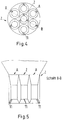
Fig. 4 eine Mehrfachdüse mit Leitschaufeln im Gaseintritt in der Draufsicht zeigt; und -
Fig. 5 eine Mehrfachdüse mit Leitschaufeln im Gaseintritt in der Seitenansicht zeigt.
-
Fig. 1 a flow diagram of the method according to the invention shows; -
Fig. 2 shows a non-inventive single nozzle with vanes in the gas inlet in the side view, which is the detail "Y" ofFig. 1 acting; -
Fig. 3 shows a non-inventive individual nozzle with vanes in the gas inlet in plan view; -
Fig. 4 shows a multi-nozzle with vanes in the gas inlet in plan view; and -
Fig. 5 a multi-nozzle with vanes in the gas inlet in the side view shows.
Zur optimalen Einstellung der Absorptionstemperatur, die 5 bis 30°C über der Kühlgrenztemperatur der in der Wirbelschicht befindlichen Feststoffe liegt, wird Wasser im unteren konusförmigen Absorber (5) eingedüst.For optimal adjustment of the absorption temperature, which is 5 to 30 ° C above the cooling limit temperature of the solids present in the fluidized bed, water is injected in the lower conical absorber (5).
Die sauren Bestandteile des Abgases reagieren in der expandierten sog. zirkulierenden Wirbelschicht zu den festen Reaktionsprodukten, die zusammen mit den im Rohgas enthaltenen Feststoffen, wie Flugasche, und dem Sorbens die expandierte Wirbelschicht bilden.The acidic components of the exhaust gas react in the expanded one so-called circulating fluidized bed to the solid reaction products, which together with the solids contained in the raw gas, such as fly ash, and the sorbent form the expanded fluidized bed.
Über eine Leitung (8) gelangt das Gas-Feststoffgemisch nach Durchlaufen des Wirbelschichtreaktors in ein Filtersystem mit Feststoffabscheider (7), wo das Gas entstaubt wird. Das entstaubte Reingas verlässt den Filter über die Leitung (9) und kann bei Teillast der Anlage wieder der Rohgasleitung (1) über die Rückführleitung (10) zugeführt werden, so dass der Wirbelschichtreaktor immer unabhängig vom Rohgasstrom bei optimaler Gasgeschwindigkeit und damit optimaler Fluiddynamik betrieben werden kann.After passing through the fluidized-bed reactor, the gas-solid mixture passes through a line (8) into a filter system with solids separator (7), where the gas is dedusted. The dedusted clean gas leaves the filter via line (9) and can at part load of the system again the crude gas line (1) via the return line (10) are fed, so that the fluidized bed reactor are always operated independently of the raw gas flow at optimum gas velocity and thus optimal fluid dynamics can.
Feststoffe können dem Wirbelschichtreaktor über eine Leitung (6) wieder zugeführt werden. Insbesondere ist eine Rückführung des Sorbens über die Leitung (6) vorteilhaft. Der Austrag des Reaktionsproduktes findet über die Leitung (12) statt.Solids can be fed back to the fluidized bed reactor via a line (6). In particular, a return of the sorbent via the line (6) is advantageous. The discharge of the reaction product takes place via the line (12).
Die
In den
Die venturiartigen Düsen werden mit 30-70m/s, vorzugsweise mit 50m/s betrieben. Der Eintrittskonus weist vorzugsweise 30° von der Senkrechten auf, der Austrittskonus 20° von der Senkrechten. Die Konstruktion ist vornehmlich auf eine Minimierung des Gesamtdruckverlustes des Düsensystems hin ausgelegt.The venturi-type nozzles are operated at 30-70m / s, preferably at 50m / s. The inlet cone preferably has 30 ° from the vertical, the outlet cone 20 ° from the vertical. The design is designed primarily to minimize the overall pressure loss of the nozzle system.
In den
Bei Mehrfachdüsen beträgt der Austrittskonus 10° von der Senkrechten. Mehrfachdüsen enden im Konus mit dem Öffnungswinkel von 20° von der Senkrechten. Bei einer optimalen Ausgestaltung der Mehrfachdüsen laufen alle Düsen mit derselben Geschwindigkeit.For multiple nozzles, the exit cone is 10 ° from the vertical. Multiple nozzles end in the cone with the opening angle of 20 ° from the vertical. With an optimal configuration of the multiple nozzles all nozzles run at the same speed.
- 1.1.
- Rohgasleitungraw gas
- 2.Second
- Düse (Einzel- oder Mehrfachdüse)Nozzle (single or multiple nozzle)
- 3.Third
- WirbelschichtreaktorFluidized bed reactor
- 4.4th
- Leitung des SorbensHead of the sorbent
- 5.5th
- konusförmiger Bereich des Wirbelschichtreaktorscone-shaped region of the fluidized bed reactor
- 6.6th
- Rezirkulation des SorbensRecirculation of the sorbent
- 7.7th
- Filtersystem mit FeststoffabscheiderFilter system with solids separator
- 8.8th.
- Leitungmanagement
- 9.9th
- Leitungmanagement
- 10.10th
- Rückführungsleitung des gereinigten RohgasesReturn line of the purified raw gas
- 11.11th
- Leitschaufelvane
- 12.12th
- Austrag des ReaktionsproduktesDischarge of the reaction product
- A.A.
- Düse im äußeren Ring einer MehrfachdüseNozzle in the outer ring of a multi-nozzle
- Z.Z.
- zentrale Düse einer Mehrfachdüsecentral nozzle of a multiple nozzle
Claims (12)
- Process for purifying exhaust gases, in which process an exhaust gas is brought together with a sorbent in a fluidized bed reactor (3), solids are separated in a subsequent filter system (7) and subsequently the sorbent is fed back up to 99 % to the fluidized bed reactor (3), wherein• the gas is rotated about the flow axis in the fluidized bed reactor (3), the rotational movement of the gas being achieved by installations in nozzles (2) located in the gas and sorbent injection region of the fluidized bed reactor (3), and• the acidic components of the exhaust gas in an expanded so-called circulating fluidised bed react to the solid reaction products, which together with the solids contained in the raw gas such as fly ash and the sorbent form the expanded fluidised bed, and• the nozzles (2) are multiple nozzles and the installations in the multiple nozzles are guide vanes (11), and• in the fluidized bed reactor (3), a gas velocity relative to the empty reactor of 2 m/s to 10 m/s, and• an average residence time for solids of 15 min to 200 min, and• an average solids load of 1 kg/m3 to 10 kg/m3 is set.
- Process according to claim 1, characterized in that the rotational movement of the gas is additionally produced by the inclination of the nozzles (2) and/or by the design of the supply line in the gas and sorbent injection area itself.
- Process according to one of claims 1 or 2, characterized in that the sorbent is introduced into the fluidized bed reactor (7) below the multiple nozzles (2), the particles recycled from the solids separator (7) are introduced below or above the multiple nozzles (2), and water is introduced above the multiple nozzles (2).
- Process according to one of claims 1 to 3, characterized in that the fluidized bed reactor (3) is operated at a temperature of 5 °C to 30 °C above the cooling limit temperature of the solids present in the fluidized bed reactor (3), the optimum reaction temperature being adjusted by injecting water.
- Process according to one of claims 1 to 4, characterized in that 20 % to 99 % of the solids separated in the filter are fed back into the fluidized bed reactor (3).
- Process according to one of claims 1 to 5, characterized in that the average residence time of solids at one-time passage through the fluidized bed reactor (3) is between 5 sec and 60 sec and/or the minimum gas residence time in the absorber (7) is 2 sec.
- Process according to one of claims 1 to 6, characterized in that the solid sorbent has a particle diameter d50 of 1 µm to 20 µm.
- Process according to one of claims 1 to 7, characterized in that the cleaned gas is returned of from 0 % to 100 % to the raw gas inlet.
- Device for carrying out a process according to one of claims 1 to 8 for cleaning exhaust gases in a fluidized bed reactor (3), in which the gas-solid mixture after passing through the fluidized bed reactor (3) is passed via a line (8) into a filter system with a solids separator (7), where the gas is de-dusted, the solids are returned to the fluidized bed reactor (3) via a line (6), the de-dusted clean gas exits the filter (7) via a line (9), and the reaction product is discharged via another line (12), wherein
the gas and sorbent injection area of the fluidized bed reactor (3) is equipped such that the raw gas can be set into a rotational movement around the flow axis in the fluidized bed reactor (3), wherein for generating the rotational movement, nozzles (2) with internal installations are being provided in the gas and sorbent injection area of the fluidized bed reactor (3), and wherein the nozzles (2) are multiple nozzles and the installations in the multiple nozzles are guide vanes (11). - Device according to claim 9, characterized in that the rotational movement of the gas is additionally generated by the inclination of the nozzles (2) and/or by the design of the supply line in the gas and sorbent injection area itself.
- Device according to one of claims 9 or 10, characterized in that the nozzles (2) are venturi nozzles.
- Device according to one of claims 9 to 11, characterized in that given a plurality of guide vanes (11) in a nozzle (2), these are aligned in such a way that the gas is brought into a uniform rotation.
Priority Applications (4)
| Application Number | Priority Date | Filing Date | Title |
|---|---|---|---|
| PL12726626T PL2744589T3 (en) | 2011-08-17 | 2012-06-11 | Method and device for cleaning exhaust gases by way of fluidized bed reactors |
| RS20190477A RS58763B1 (en) | 2011-08-17 | 2012-06-11 | Method and device for cleaning exhaust gases by way of fluidized bed reactors |
| SI201231590T SI2744589T1 (en) | 2011-08-17 | 2012-06-11 | Method and device for cleaning exhaust gases by way of fluidized bed reactors |
| HRP20190700TT HRP20190700T1 (en) | 2011-08-17 | 2019-04-15 | Method and device for cleaning exhaust gases by way of fluidized bed reactors |
Applications Claiming Priority (2)
| Application Number | Priority Date | Filing Date | Title |
|---|---|---|---|
| DE102011052788.5A DE102011052788B4 (en) | 2011-08-17 | 2011-08-17 | Process and apparatus for purifying exhaust gases |
| PCT/EP2012/061001 WO2013023800A1 (en) | 2011-08-17 | 2012-06-11 | Method and device for cleaning exhaust gases by way of fluidized bed reactors |
Publications (2)
| Publication Number | Publication Date |
|---|---|
| EP2744589A1 EP2744589A1 (en) | 2014-06-25 |
| EP2744589B1 true EP2744589B1 (en) | 2019-01-23 |
Family
ID=46245587
Family Applications (1)
| Application Number | Title | Priority Date | Filing Date |
|---|---|---|---|
| EP12726626.0A Active EP2744589B1 (en) | 2011-08-17 | 2012-06-11 | Method and device for cleaning exhaust gases by way of fluidized bed reactors |
Country Status (13)
| Country | Link |
|---|---|
| US (1) | US9040004B2 (en) |
| EP (1) | EP2744589B1 (en) |
| CN (1) | CN103857459B (en) |
| AU (1) | AU2012297142A1 (en) |
| DE (1) | DE102011052788B4 (en) |
| HR (1) | HRP20190700T1 (en) |
| HU (1) | HUE043177T2 (en) |
| LT (1) | LT2744589T (en) |
| PL (1) | PL2744589T3 (en) |
| RS (1) | RS58763B1 (en) |
| SI (1) | SI2744589T1 (en) |
| TR (1) | TR201905705T4 (en) |
| WO (1) | WO2013023800A1 (en) |
Families Citing this family (6)
| Publication number | Priority date | Publication date | Assignee | Title |
|---|---|---|---|---|
| KR101729460B1 (en) * | 2014-01-31 | 2017-04-21 | 아멕 포스터 휠러 에너지아 오와이 | A method of and a scrubber for removing pollutant compounds from a gas stream |
| DE102015122230A1 (en) * | 2015-12-18 | 2017-06-22 | Graf Enviropro Gmbh | Method for exhaust gas purification by means of a fluidized bed flow reactor |
| JP7193254B2 (en) * | 2017-05-26 | 2022-12-20 | ケミカル アンド メタル テクノロジーズ リミテッド ライアビリティ カンパニー | Reconfigurable segmental polluted effluent capture and collection system and method of use using fluidized bed apparatus with tilting and/or agitation methods |
| EP3620227A1 (en) | 2018-09-05 | 2020-03-11 | Fujian Lonjing Environment Technology Co., Ltd. | Apparatus and process for removal of sulfur dioxide from flue gas |
| CN109589777A (en) * | 2018-12-17 | 2019-04-09 | 北京博奇电力科技有限公司 | A kind of Multi-stage spiral circulating fluid bed desulfurization device and its sulfur method |
| CN114832587B (en) * | 2022-06-09 | 2022-11-25 | 山东泰开环保科技有限公司 | Slag flushing water desulfurization system |
Citations (3)
| Publication number | Priority date | Publication date | Assignee | Title |
|---|---|---|---|---|
| WO2005030368A1 (en) * | 2003-08-15 | 2005-04-07 | Wuhan Kaidi Electric Power Co. Ltd. | One tower-multibeds circulating fluidization large-scale dry desulfurizating process for flue gas |
| CN1820836A (en) * | 2006-01-25 | 2006-08-23 | 山东大学 | Circulation fluidized bed swirl-direct flow composite fluidizing device |
| CN101648112A (en) * | 2009-08-26 | 2010-02-17 | 福建龙净脱硫脱硝工程有限公司 | Flue gas purifying device and flue gas purifying method for trapping inhalable particulate |
Family Cites Families (16)
| Publication number | Priority date | Publication date | Assignee | Title |
|---|---|---|---|---|
| US3885934A (en) * | 1971-09-02 | 1975-05-27 | Heat Fluid Engineering Corp | Centrifugal tuyere for gas separator |
| GB1571222A (en) | 1977-03-10 | 1980-07-09 | Ardal Og Sunndal Verk | Process and apparatus for treatment of waste gases |
| EP0027690B1 (en) * | 1979-10-18 | 1984-01-25 | Imperial Chemical Industries Plc | Process and apparatus for the mixing of fluids and solids |
| IT1150650B (en) | 1982-03-10 | 1986-12-17 | Montedison Spa | FLUID BED REACTOR |
| DK348583D0 (en) * | 1983-07-29 | 1983-07-29 | Smidth & Co As F L | METHOD AND APPARATUS FOR REMOVAL OF SULFUR OXIDES FROM HOT ROEGGAS BY THE TOUR METHOD |
| DE3526008A1 (en) * | 1985-07-20 | 1987-01-22 | Metallgesellschaft Ag | METHOD FOR REMOVING POLLUTANTS FROM SMOKE GAS |
| FI82612C (en) * | 1987-05-08 | 1991-04-10 | Ahlstroem Oy | Process and apparatus for treating process gases |
| JPS63310633A (en) * | 1987-06-10 | 1988-12-19 | Sumitomo Electric Ind Ltd | Device for synthesizing compound powder in vapor phase |
| US5238659A (en) * | 1989-05-23 | 1993-08-24 | Kawasaki Jukogyo Kabushiki Kaisha | Moving granular bed dust removal and reaction apparatus |
| US5662049A (en) * | 1994-05-30 | 1997-09-02 | Ishikawajima-Harima Jukogyo Kabushiki Kaisha | Combustion method and apparatus |
| DE19517863C2 (en) | 1995-05-16 | 1998-10-22 | Metallgesellschaft Ag | Process for dry desulfurization of a combustion exhaust gas |
| FR2775061B1 (en) | 1998-02-16 | 2000-03-10 | Gec Alsthom Stein Ind | CIRCULATING FLUIDIZED BED BOILER WITH IMPROVED NITROGEN OXIDE REDUCTION |
| DE10100595A1 (en) * | 2001-01-09 | 2002-07-18 | Joerg Peter Schuer | Process for non-toxic odor neutralization of air |
| EP1799331A1 (en) | 2004-09-22 | 2007-06-27 | Lentjes GmbH | Flue-gas purification system |
| CN200970564Y (en) * | 2006-11-18 | 2007-11-07 | 陈盾 | Venturi atomizer |
| EP2263780B1 (en) | 2009-06-18 | 2017-12-06 | ENVIROSERV GmbH | Exhaust gas purification assembly with nozzle variation |
-
2011
- 2011-08-17 DE DE102011052788.5A patent/DE102011052788B4/en not_active Expired - Fee Related
-
2012
- 2012-06-11 WO PCT/EP2012/061001 patent/WO2013023800A1/en active Application Filing
- 2012-06-11 SI SI201231590T patent/SI2744589T1/en unknown
- 2012-06-11 TR TR2019/05705T patent/TR201905705T4/en unknown
- 2012-06-11 HU HUE12726626A patent/HUE043177T2/en unknown
- 2012-06-11 PL PL12726626T patent/PL2744589T3/en unknown
- 2012-06-11 RS RS20190477A patent/RS58763B1/en unknown
- 2012-06-11 AU AU2012297142A patent/AU2012297142A1/en not_active Abandoned
- 2012-06-11 US US14/239,173 patent/US9040004B2/en active Active
- 2012-06-11 EP EP12726626.0A patent/EP2744589B1/en active Active
- 2012-06-11 CN CN201280040037.6A patent/CN103857459B/en active Active
- 2012-06-11 LT LTEP12726626.0T patent/LT2744589T/en unknown
-
2019
- 2019-04-15 HR HRP20190700TT patent/HRP20190700T1/en unknown
Patent Citations (3)
| Publication number | Priority date | Publication date | Assignee | Title |
|---|---|---|---|---|
| WO2005030368A1 (en) * | 2003-08-15 | 2005-04-07 | Wuhan Kaidi Electric Power Co. Ltd. | One tower-multibeds circulating fluidization large-scale dry desulfurizating process for flue gas |
| CN1820836A (en) * | 2006-01-25 | 2006-08-23 | 山东大学 | Circulation fluidized bed swirl-direct flow composite fluidizing device |
| CN101648112A (en) * | 2009-08-26 | 2010-02-17 | 福建龙净脱硫脱硝工程有限公司 | Flue gas purifying device and flue gas purifying method for trapping inhalable particulate |
Also Published As
| Publication number | Publication date |
|---|---|
| US9040004B2 (en) | 2015-05-26 |
| LT2744589T (en) | 2019-05-10 |
| RS58763B1 (en) | 2019-06-28 |
| CN103857459A (en) | 2014-06-11 |
| HRP20190700T1 (en) | 2019-07-12 |
| US20140356264A1 (en) | 2014-12-04 |
| PL2744589T3 (en) | 2019-08-30 |
| DE102011052788B4 (en) | 2014-03-20 |
| TR201905705T4 (en) | 2019-05-21 |
| SI2744589T1 (en) | 2019-06-28 |
| AU2012297142A1 (en) | 2014-03-13 |
| EP2744589A1 (en) | 2014-06-25 |
| DE102011052788A1 (en) | 2013-02-21 |
| WO2013023800A1 (en) | 2013-02-21 |
| CN103857459B (en) | 2017-03-22 |
| HUE043177T2 (en) | 2019-08-28 |
Similar Documents
| Publication | Publication Date | Title |
|---|---|---|
| EP2744589B1 (en) | Method and device for cleaning exhaust gases by way of fluidized bed reactors | |
| DE69913994T2 (en) | FLASH PYROLYSIS IN A CYCLONE | |
| EP0211458B2 (en) | Process for removing noxious materials from fumes | |
| EP0129273B1 (en) | Process for the separation of pollutants from waste gases | |
| DE10260740B4 (en) | Process and plant for removing gaseous pollutants from exhaust gases | |
| EP0104335B2 (en) | Process for the purification of exhaust gases | |
| WO2009021258A1 (en) | Fluidized bed reactor system | |
| EP2579975A1 (en) | Fluidized bed reactor system | |
| DE2538193A1 (en) | DEVICE FOR GAS DISTRIBUTION FOR FLUID BEDS | |
| DE10260739B3 (en) | Process and plant for producing metal oxide from metal compounds | |
| CH672264A5 (en) | ||
| WO2016030207A1 (en) | Purification device, use of a purification device and method for purifying a waste-gas flow | |
| US5946818A (en) | Process and apparatus for drying liquid-borne solid material | |
| DE2129231C3 (en) | Process for separating sulfur dioxide from the flue gases of fuels containing sulfur | |
| EP1537905B1 (en) | Process and apparatus for sorption of contaminants from flue gases by means of a fluidised bed | |
| DE2910537C2 (en) | Process for regenerating the dry and fine-grain additives from an exhaust gas purification device | |
| WO2017101913A2 (en) | Method for separating gaseous or particulate materials from a gas flow by means of a fluidised-bed flow reactor | |
| DE3430212A1 (en) | Process for generating gas from carbonaceous fuels | |
| EP3072573B1 (en) | Gas purification system and method for the purification of gases with recirculation of purified gas | |
| DE102008009132B4 (en) | Process and apparatus for burning solid fuels | |
| DE3920146C2 (en) | Method and device for incinerating and desulphurizing gaseous unburned gases and effluents containing SO2, SO3 and / or H2S in the circulating bed | |
| DE2257539C3 (en) | Process for the continuous production of active calcium oxide in powder form from waste lime containing organic substances in the sugar industry | |
| DE1592140C (en) | Apparatus for the production of anhydrous alumina from alumina hydrate | |
| DE2257539B2 (en) | PROCESS FOR THE CONTINUOUS PRODUCTION OF POWDERED, ACTIVE CALCIUM OXIDE FROM THE WASTE LIME OF THE SUGAR INDUSTRY, CONTAINING ORGANIC MATERIALS | |
| WO2009006964A2 (en) | Production and cooling of gaseous coal gasification products |
Legal Events
| Date | Code | Title | Description |
|---|---|---|---|
| PUAI | Public reference made under article 153(3) epc to a published international application that has entered the european phase |
Free format text: ORIGINAL CODE: 0009012 |
|
| 17P | Request for examination filed |
Effective date: 20140214 |
|
| AK | Designated contracting states |
Kind code of ref document: A1 Designated state(s): AL AT BE BG CH CY CZ DE DK EE ES FI FR GB GR HR HU IE IS IT LI LT LU LV MC MK MT NL NO PL PT RO RS SE SI SK SM TR |
|
| RAP1 | Party data changed (applicant data changed or rights of an application transferred) |
Owner name: FUJIAN LONJING ENVIRONMENT TECHNOLOGY CO., LTD. Owner name: SAUER, HARALD |
|
| RIN1 | Information on inventor provided before grant (corrected) |
Inventor name: SAUER, HARALD |
|
| DAX | Request for extension of the european patent (deleted) | ||
| STAA | Information on the status of an ep patent application or granted ep patent |
Free format text: STATUS: EXAMINATION IS IN PROGRESS |
|
| 17Q | First examination report despatched |
Effective date: 20171117 |
|
| GRAP | Despatch of communication of intention to grant a patent |
Free format text: ORIGINAL CODE: EPIDOSNIGR1 |
|
| STAA | Information on the status of an ep patent application or granted ep patent |
Free format text: STATUS: GRANT OF PATENT IS INTENDED |
|
| INTG | Intention to grant announced |
Effective date: 20180405 |
|
| GRAS | Grant fee paid |
Free format text: ORIGINAL CODE: EPIDOSNIGR3 |
|
| GRAA | (expected) grant |
Free format text: ORIGINAL CODE: 0009210 |
|
| STAA | Information on the status of an ep patent application or granted ep patent |
Free format text: STATUS: THE PATENT HAS BEEN GRANTED |
|
| AK | Designated contracting states |
Kind code of ref document: B1 Designated state(s): AL AT BE BG CH CY CZ DE DK EE ES FI FR GB GR HR HU IE IS IT LI LT LU LV MC MK MT NL NO PL PT RO RS SE SI SK SM TR |
|
| REG | Reference to a national code |
Ref country code: GB Ref legal event code: FG4D Free format text: NOT ENGLISH |
|
| REG | Reference to a national code |
Ref country code: CH Ref legal event code: EP |
|
| REG | Reference to a national code |
Ref country code: AT Ref legal event code: REF Ref document number: 1090990 Country of ref document: AT Kind code of ref document: T Effective date: 20190215 |
|
| REG | Reference to a national code |
Ref country code: IE Ref legal event code: FG4D Free format text: LANGUAGE OF EP DOCUMENT: GERMAN |
|
| REG | Reference to a national code |
Ref country code: DE Ref legal event code: R096 Ref document number: 502012014205 Country of ref document: DE |
|
| REG | Reference to a national code |
Ref country code: HR Ref legal event code: TUEP Ref document number: P20190700 Country of ref document: HR |
|
| REG | Reference to a national code |
Ref country code: RO Ref legal event code: EPE |
|
| REG | Reference to a national code |
Ref country code: NL Ref legal event code: MP Effective date: 20190123 |
|
| REG | Reference to a national code |
Ref country code: EE Ref legal event code: FG4A Ref document number: E017256 Country of ref document: EE Effective date: 20190417 |
|
| PG25 | Lapsed in a contracting state [announced via postgrant information from national office to epo] |
Ref country code: NL Free format text: LAPSE BECAUSE OF FAILURE TO SUBMIT A TRANSLATION OF THE DESCRIPTION OR TO PAY THE FEE WITHIN THE PRESCRIBED TIME-LIMIT Effective date: 20190123 |
|
| REG | Reference to a national code |
Ref country code: HR Ref legal event code: ODRP Ref document number: P20190700 Country of ref document: HR Payment date: 20190611 Year of fee payment: 8 |
|
| REG | Reference to a national code |
Ref country code: HR Ref legal event code: T1PR Ref document number: P20190700 Country of ref document: HR |
|
| PG25 | Lapsed in a contracting state [announced via postgrant information from national office to epo] |
Ref country code: ES Free format text: LAPSE BECAUSE OF FAILURE TO SUBMIT A TRANSLATION OF THE DESCRIPTION OR TO PAY THE FEE WITHIN THE PRESCRIBED TIME-LIMIT Effective date: 20190123 Ref country code: PT Free format text: LAPSE BECAUSE OF FAILURE TO SUBMIT A TRANSLATION OF THE DESCRIPTION OR TO PAY THE FEE WITHIN THE PRESCRIBED TIME-LIMIT Effective date: 20190523 Ref country code: NO Free format text: LAPSE BECAUSE OF FAILURE TO SUBMIT A TRANSLATION OF THE DESCRIPTION OR TO PAY THE FEE WITHIN THE PRESCRIBED TIME-LIMIT Effective date: 20190423 Ref country code: FI Free format text: LAPSE BECAUSE OF FAILURE TO SUBMIT A TRANSLATION OF THE DESCRIPTION OR TO PAY THE FEE WITHIN THE PRESCRIBED TIME-LIMIT Effective date: 20190123 Ref country code: SE Free format text: LAPSE BECAUSE OF FAILURE TO SUBMIT A TRANSLATION OF THE DESCRIPTION OR TO PAY THE FEE WITHIN THE PRESCRIBED TIME-LIMIT Effective date: 20190123 |
|
| REG | Reference to a national code |
Ref country code: SK Ref legal event code: T3 Ref document number: E 30829 Country of ref document: SK |
|
| REG | Reference to a national code |
Ref country code: HU Ref legal event code: AG4A Ref document number: E043177 Country of ref document: HU |
|
| PG25 | Lapsed in a contracting state [announced via postgrant information from national office to epo] |
Ref country code: GR Free format text: LAPSE BECAUSE OF FAILURE TO SUBMIT A TRANSLATION OF THE DESCRIPTION OR TO PAY THE FEE WITHIN THE PRESCRIBED TIME-LIMIT Effective date: 20190424 Ref country code: IS Free format text: LAPSE BECAUSE OF FAILURE TO SUBMIT A TRANSLATION OF THE DESCRIPTION OR TO PAY THE FEE WITHIN THE PRESCRIBED TIME-LIMIT Effective date: 20190523 |
|
| REG | Reference to a national code |
Ref country code: DE Ref legal event code: R097 Ref document number: 502012014205 Country of ref document: DE |
|
| PG25 | Lapsed in a contracting state [announced via postgrant information from national office to epo] |
Ref country code: DK Free format text: LAPSE BECAUSE OF FAILURE TO SUBMIT A TRANSLATION OF THE DESCRIPTION OR TO PAY THE FEE WITHIN THE PRESCRIBED TIME-LIMIT Effective date: 20190123 Ref country code: IT Free format text: LAPSE BECAUSE OF FAILURE TO SUBMIT A TRANSLATION OF THE DESCRIPTION OR TO PAY THE FEE WITHIN THE PRESCRIBED TIME-LIMIT Effective date: 20190123 |
|
| PG25 | Lapsed in a contracting state [announced via postgrant information from national office to epo] |
Ref country code: SM Free format text: LAPSE BECAUSE OF FAILURE TO SUBMIT A TRANSLATION OF THE DESCRIPTION OR TO PAY THE FEE WITHIN THE PRESCRIBED TIME-LIMIT Effective date: 20190123 |
|
| PLBE | No opposition filed within time limit |
Free format text: ORIGINAL CODE: 0009261 |
|
| STAA | Information on the status of an ep patent application or granted ep patent |
Free format text: STATUS: NO OPPOSITION FILED WITHIN TIME LIMIT |
|
| 26N | No opposition filed |
Effective date: 20191024 |
|
| PG25 | Lapsed in a contracting state [announced via postgrant information from national office to epo] |
Ref country code: MC Free format text: LAPSE BECAUSE OF FAILURE TO SUBMIT A TRANSLATION OF THE DESCRIPTION OR TO PAY THE FEE WITHIN THE PRESCRIBED TIME-LIMIT Effective date: 20190123 |
|
| REG | Reference to a national code |
Ref country code: CH Ref legal event code: PL |
|
| REG | Reference to a national code |
Ref country code: BE Ref legal event code: MM Effective date: 20190630 |
|
| PG25 | Lapsed in a contracting state [announced via postgrant information from national office to epo] |
Ref country code: CH Free format text: LAPSE BECAUSE OF NON-PAYMENT OF DUE FEES Effective date: 20190630 Ref country code: LU Free format text: LAPSE BECAUSE OF NON-PAYMENT OF DUE FEES Effective date: 20190611 Ref country code: BE Free format text: LAPSE BECAUSE OF NON-PAYMENT OF DUE FEES Effective date: 20190630 Ref country code: LI Free format text: LAPSE BECAUSE OF NON-PAYMENT OF DUE FEES Effective date: 20190630 |
|
| REG | Reference to a national code |
Ref country code: HR Ref legal event code: ODRP Ref document number: P20190700 Country of ref document: HR Payment date: 20200604 Year of fee payment: 9 |
|
| PG25 | Lapsed in a contracting state [announced via postgrant information from national office to epo] |
Ref country code: FR Free format text: LAPSE BECAUSE OF NON-PAYMENT OF DUE FEES Effective date: 20190630 |
|
| REG | Reference to a national code |
Ref country code: AT Ref legal event code: MM01 Ref document number: 1090990 Country of ref document: AT Kind code of ref document: T Effective date: 20190611 |
|
| PG25 | Lapsed in a contracting state [announced via postgrant information from national office to epo] |
Ref country code: AT Free format text: LAPSE BECAUSE OF NON-PAYMENT OF DUE FEES Effective date: 20190611 |
|
| REG | Reference to a national code |
Ref country code: HU Ref legal event code: HC9C Owner name: SAUER, HARALD, DE Ref country code: HU Ref legal event code: HC9C Owner name: FUJIAN LONJING ENVIRONMENT TECHNOLOGY CO., LTD, CN |
|
| REG | Reference to a national code |
Ref country code: EE Ref legal event code: HC1A Ref document number: E017256 Country of ref document: EE |
|
| PG25 | Lapsed in a contracting state [announced via postgrant information from national office to epo] |
Ref country code: CY Free format text: LAPSE BECAUSE OF FAILURE TO SUBMIT A TRANSLATION OF THE DESCRIPTION OR TO PAY THE FEE WITHIN THE PRESCRIBED TIME-LIMIT Effective date: 20190123 |
|
| REG | Reference to a national code |
Ref country code: HR Ref legal event code: ODRP Ref document number: P20190700 Country of ref document: HR Payment date: 20210520 Year of fee payment: 10 |
|
| PG25 | Lapsed in a contracting state [announced via postgrant information from national office to epo] |
Ref country code: MT Free format text: LAPSE BECAUSE OF FAILURE TO SUBMIT A TRANSLATION OF THE DESCRIPTION OR TO PAY THE FEE WITHIN THE PRESCRIBED TIME-LIMIT Effective date: 20190123 |
|
| PG25 | Lapsed in a contracting state [announced via postgrant information from national office to epo] |
Ref country code: MK Free format text: LAPSE BECAUSE OF FAILURE TO SUBMIT A TRANSLATION OF THE DESCRIPTION OR TO PAY THE FEE WITHIN THE PRESCRIBED TIME-LIMIT Effective date: 20190123 |
|
| REG | Reference to a national code |
Ref country code: HR Ref legal event code: ODRP Ref document number: P20190700 Country of ref document: HR Payment date: 20220609 Year of fee payment: 11 |
|
| REG | Reference to a national code |
Ref country code: HU Ref legal event code: HC9C Owner name: SAUER, HARALD, DE Ref country code: HU Ref legal event code: HC9C Owner name: FUJIAN LONJING ENVIRONMENT TECHNOLOGY CO., LTD., CN |
|
| REG | Reference to a national code |
Ref country code: HR Ref legal event code: ODRP Ref document number: P20190700 Country of ref document: HR Payment date: 20230517 Year of fee payment: 12 |
|
| PGFP | Annual fee paid to national office [announced via postgrant information from national office to epo] |
Ref country code: RS Payment date: 20230607 Year of fee payment: 12 Ref country code: RO Payment date: 20230526 Year of fee payment: 12 Ref country code: LT Payment date: 20230523 Year of fee payment: 12 Ref country code: IE Payment date: 20230519 Year of fee payment: 12 Ref country code: EE Payment date: 20230523 Year of fee payment: 12 Ref country code: DE Payment date: 20230613 Year of fee payment: 12 Ref country code: CZ Payment date: 20230524 Year of fee payment: 12 Ref country code: BG Payment date: 20230530 Year of fee payment: 12 |
|
| PGFP | Annual fee paid to national office [announced via postgrant information from national office to epo] |
Ref country code: TR Payment date: 20230525 Year of fee payment: 12 Ref country code: SK Payment date: 20230518 Year of fee payment: 12 Ref country code: SI Payment date: 20230522 Year of fee payment: 12 Ref country code: PL Payment date: 20230601 Year of fee payment: 12 Ref country code: LV Payment date: 20230523 Year of fee payment: 12 Ref country code: HU Payment date: 20230525 Year of fee payment: 12 Ref country code: HR Payment date: 20230517 Year of fee payment: 12 |
|
| PGFP | Annual fee paid to national office [announced via postgrant information from national office to epo] |
Ref country code: GB Payment date: 20230620 Year of fee payment: 12 |
|
| PGFP | Annual fee paid to national office [announced via postgrant information from national office to epo] |
Ref country code: AL Payment date: 20230626 Year of fee payment: 12 |