EP2744188A2 - Recording data generation apparatus, recording system, program, recording data generation method and image data display method - Google Patents
Recording data generation apparatus, recording system, program, recording data generation method and image data display method Download PDFInfo
- Publication number
- EP2744188A2 EP2744188A2 EP13196649.1A EP13196649A EP2744188A2 EP 2744188 A2 EP2744188 A2 EP 2744188A2 EP 13196649 A EP13196649 A EP 13196649A EP 2744188 A2 EP2744188 A2 EP 2744188A2
- Authority
- EP
- European Patent Office
- Prior art keywords
- color
- pixel
- recording
- image data
- designated
- Prior art date
- Legal status (The legal status is an assumption and is not a legal conclusion. Google has not performed a legal analysis and makes no representation as to the accuracy of the status listed.)
- Granted
Links
Images





Classifications
-
- G—PHYSICS
- G06—COMPUTING OR CALCULATING; COUNTING
- G06K—GRAPHICAL DATA READING; PRESENTATION OF DATA; RECORD CARRIERS; HANDLING RECORD CARRIERS
- G06K15/00—Arrangements for producing a permanent visual presentation of the output data, e.g. computer output printers
- G06K15/02—Arrangements for producing a permanent visual presentation of the output data, e.g. computer output printers using printers
- G06K15/18—Conditioning data for presenting it to the physical printing elements
- G06K15/1867—Post-processing of the composed and rasterized print image
- G06K15/1872—Image enhancement
- G06K15/1878—Adjusting colours
-
- H—ELECTRICITY
- H04—ELECTRIC COMMUNICATION TECHNIQUE
- H04N—PICTORIAL COMMUNICATION, e.g. TELEVISION
- H04N1/00—Scanning, transmission or reproduction of documents or the like, e.g. facsimile transmission; Details thereof
- H04N1/46—Colour picture communication systems
-
- H—ELECTRICITY
- H04—ELECTRIC COMMUNICATION TECHNIQUE
- H04N—PICTORIAL COMMUNICATION, e.g. TELEVISION
- H04N1/00—Scanning, transmission or reproduction of documents or the like, e.g. facsimile transmission; Details thereof
- H04N1/46—Colour picture communication systems
- H04N1/56—Processing of colour picture signals
- H04N1/60—Colour correction or control
- H04N1/62—Retouching, i.e. modification of isolated colours only or in isolated picture areas only
Definitions
- the present invention relates to a recording data generation apparatus, a recording system, a program, a recording data generation method and an image data display method.
- recording data generation apparatuses each generating recording data for use in recording operation of a recording apparatus on the basis image data.
- processing for converting a specific color in image data into a different color has been frequently performed.
- JP-A-63-46071 there has been disclosed an image processing method which makes it possible to, when converting a specific color in image data into a different color, select a post-conversion color from among a plurality of colors.
- JP-A-63-46071 is not a technology which makes it easy to, when converting a specific color within a desired area of image data into a different color, select the specific color.
- An advantage of some aspects of the invention is to make it easy to, when converting a specific color within a desired area of image data into a different color, select the specific color.
- a recording data generation apparatus which generates recording data for use in recording operation of a recording apparatus on the basis of image data, includes a display portion that displays the image data; a selection portion that allows selection of a partial pixel from among pixels constituting the image data displayed on the display portion; a color range setting portion that allows setting a color range on the basis of a color of the partial pixel; a determination portion that determines whether or not a pixel constituting the image data is a pixel falling within the color range; a determination practice portion that causes the determination made by the determination portion to be sequentially practiced with respect to a pixel adjacent to a determination-completed pixel on the basis of the partial pixel until the pixel adjacent to a determination-completed pixel becomes a pixel not falling within the color range; a pixel designation portion that designates at least one pixel which is determined as a pixel falling within the color range by the determination portion; a color conversion portion that converts a color of each of the at least one pixel designated
- allowing setting a color range on the basis of a color of the partial pixel corresponds to a case where, for example, when a color of the partial pixel is represented by RGB values each being one of 256 gray-scale levels, the relevant color range can be set so as to cover, for each of RGB colors, a range having a desired amplitude relative to its center which is placed at a corresponding one of the RGB values representing the color of the partial pixel.
- a different configuration represented by L * a * b * values or the like may be employed.
- "until the pixel adjacent to a determination-completed pixel becomes a pixel not falling within the color range” includes or can mean instead that the determination carried out by the determination portion continues until all pixels adjacent a determination-completed pixel either are also determination-completed pixels or do not fall within the color range.
- an area of pixels to be color converted can be made within the desired area on the basis of the partial pixel.
- a recording data generation apparatus is configured such that, in the first aspect, the color conversion portion allows the conversion of a color of each of the at least one pixel designated by the pixel designation portion into any one of a transparent color, a white color and a designated color, and the recording data generation apparatus includes a color designation portion that allows designation of any color as a color of the designated color.
- a recording data generation apparatus is configured such that, in the second aspect, a storage portion that stores therein a pre-conversion color of each of the at least one pixel designated by the pixel designation portion is further provided, and the color designation portion performs designation of a post-conversion color of each of the at least one pixel designated by the pixel designation portion by varying a pre-conversion color of the each of the at least one pixel such that an amount of the variation corresponds to an amount of a variation of a pre-conversion color which is associated with any one of the at least one pixel and is stored in the storage portion.
- a variation between post-conversion colors of any two ones of the pixels corresponds to a variation between pre-conversion colors of the any two ones of the pixels. That is, the gradation of the selected pixels before a color conversion can be kept in the gradation of the selected pixels after the color conversion.
- a recording data generation apparatus is configured such that, in the second aspect or the third aspect, the color conversion portion causes a data processing method for converting a color of each of the at least one pixel designated by the pixel designation portion into the transparent color or the white color to differ from a data processing method for converting the color of each of the at least one pixel designated by the pixel designation portion into the designated color.
- RGB data when data corresponding to each of the designated pixels is converted into data based on the transparent color or the white color, RGB data is directly converted into CMYK data, and when data corresponding to each of the designated pixels is converted into data based on the designated color, RGB data is converted into different RGB data, and then, the different RGB data is converted into CMYK data.
- a recording data generation apparatus is configured such that, in any one of the first to fourth aspects, the selection portion allows selection of a plurality of pixels from among the pixels constituting the image data, and the color range setting portion allows setting a color range on the basis of an average value of colors each associated with a corresponding one of the plurality of pixels.
- a recording data generation apparatus is configured such that, in the fifth aspect, the selection portion allows further selection of a partial pixel from at least one pixel included in the color range set by using the color range setting portion.
- a recording system includes the recording data generation apparatus according to any one of the first to sixth aspects; and a recording apparatus that performs recording on the basis of recording data generated by the recording data generation apparatus.
- a program which generates recording data for use in recording operation of a recording apparatus on the basis of image data, causes a computer to function as an apparatus including the portions of a display portion that displays the image data; a selection portion that allows selection of a partial pixel from among pixels constituting the image data displayed on the display portion; a color range setting portion that allows setting a color range on the basis of a color of the partial pixel; a determination portion that determines whether or not a pixel constituting the image data is a pixel falling within the color range; a determination practice portion that causes the determination made by the determination portion to be sequentially practiced with respect to a pixel adjacent to a determination-completed pixel on the basis of the partial pixel until the pixel adjacent to a determination-completed pixel becomes a pixel not falling within the color range; a pixel designation portion that designates at least one pixel which is determined as a pixel falling within the color range by the determination portion; a color conversion portion that converts a color of each
- a recording data generation method which is used for generating recording data for use in recording operation of a recording apparatus on the basis of image data, includes a display process of displaying the image data; a selection process of selecting a partial pixel from among pixels constituting the image data displayed on the display portion; a color range setting process of setting a color range on the basis of a color of the partial pixel; a determination practice process of causing a determination process of determining whether or not a pixel included in the pixels constituting the image data is a pixel falling within the color range to be sequentially practiced with respect to a pixel adjacent to a previously determined pixel on the basis of the partial pixel until the pixel adjacent to a previously determined pixel becomes a pixel not falling within the color range; a pixel designation process of designating at least one pixel which is determined to be a pixel falling within the color range by the determination process; a color conversion process of converting a color of each of the at least one pixel designated by the pixel designation
- An image data display method which is for use in the recording data generation apparatus according to any one of the aspects from the second aspect to the sixth aspect, includes displaying the image data on the display portion such that a color of the image data reflects a ground color of a recording target medium in the case where a color of each of the at least one pixel designated by the pixel designation portion is converted into the transparent color; displaying the image data on the display portion such that a color of the image data reflects a ground color of a recording target medium and a degree of whiteness corresponding to a recording density of a white ink in recording in a white color in the case where a color of each of the at least one pixel designated by the pixel designation portion is converted into the white color; displaying the image data on the display portion such that a color of the image data reflects a color of the designated color and a degree of whiteness corresponding to a recording density of a white ink in recording in a white color in the case where a color of each of
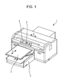
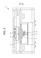
- Fig. 1 and Fig. 2 illustrate an overview perspective view and an overview plan view of a recording apparatus 1 according to an embodiment of the invention, respectively.
- the recording apparatus 1 of this embodiment is a recording apparatus configured so as to be capable of performing recording on a fabric as a recording target medium M (refer to Fig. 5 ), but is not limited to any recording apparatus configured in such a way.
- the recording apparatus 1 of this embodiment includes a medium supporting tray 2 for supporting a fabric as the recording target medium M. Further, the recording apparatus 1 includes a movement mechanism 3 for transporting the recording target medium M supported by the medium supporting tray 2 in a transportation direction A. In addition, the movement mechanism 3 of this embodiment is configured so as to move the medium supporting tray 2 (that is, so as to transport the recording target medium M supported by the medium supporting tray 2) relative to a recording head 6 (refer to Fig. 3 ). Nevertheless, the movement mechanism 3 of this embodiment may be configured so as to move the recording head 6 relative to the medium supporting tray 2 or cause the both to perform relative movement.
- the medium supporting tray 2 is supported by a stage 4.
- the medium supporting tray 2 moves in a height direction C together with the stage 4 in conjunction with the rotation of a rotation lever 5.
- the recording head 6 is installed inside the body of the recording apparatus 1. Further, the recording apparatus 1 of this embodiment forms images based on recording data by ejecting inks from the recording head 6 onto the recording target medium M which is transported being supported by the medium supporting tray 2, while reciprocating the recording head 6 in a scanning direction B intersecting with the transportation direction A.
- a position at which the recording target medium M is set on the medium supporting tray 2 is located at a front side of the recording apparatus 1 (a left lower portion of Fig. 1 ), and a recording start position is located at a back side of the recording apparatus 1 (a right upper portion of Fig. 1 ). After having moved the medium supporting tray 2 to the recording start position, the recording apparatus 1 starts recording and continues the recording while moving the medium supporting tray 2 in a direction towards the front side of the recording apparatus 1.
- the recording apparatus 1 includes a monitor 8 and a control panel 9. After having selected desired setting items on menus displayed on the monitor 8 while manipulating the control panel 9, a user can actuate the recording apparatus 1 in accordance with the selected setting items. For example, after having selected a kind of the recording target medium M to be used in subsequent recording, recording modes in the transportation direction A and the scanning direction B, and the like, a user can actuate the recording apparatus 1 in accordance with the selected setting items.
- the recording apparatus 1 includes ink cartridges (not illustrated) each containing a corresponding one of a white ink, a black ink, a cyan ink, a magenta ink and a yellow ink.
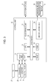
- Fig. 3 is a block diagram of the recording apparatus 1 of this embodiment.
- a control unit 10 includes a CPU 11 for performing control of the whole of the recording apparatus 1.
- the CPU 11 is electrically connected, via a system bus 12, to a ROM 13 which stores therein various control programs carried out by the CPU 11, maintenance sequences and the like, and a RAM 14 which is capable of storing data therein temporarily. Further, the CPU 11 is electrically connected to, via the system bus 12, a head driving unit 15 for driving the recording head 6. Further, the CPU 11 is electrically connected to, via the system bus 12, to a motor driving unit 18 which drives a carriage motor 16 for moving a carriage on which the recording head 6 is mounted, and which drives a transportation motor 17 for transporting the recording target medium M.
- the CPU 11 is electrically connected to, via the system bus 12, an input and output unit 19 for transmitting and receiving data and signals to/from the monitor 8, the control panel 9 and an interface 20 for performing reception of recording data, and the like, from a PC 21 constituting a recording system of this embodiment, and functioning as a recording data generation apparatus in the recording system.
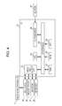
- Fig. 4 is a block diagram illustrating an electrical configuration of the PC 21 of this embodiment.
- the PC 21 includes a CPU 22 for performing control of the whole of the PC 21.
- the CPU 22 is electrically connected to, via a system bus 23, a ROM 24 for storing therein various programs carried out by the CPU 22, and the like, a RAM 25 which is capable of storing data therein temporarily, and a HDD 26 which is a data storage device. Further, the CPU 22 is electrically connected to, via the system bus 23, a CD-ROM drive 28 which is capable of reading data from a CD-ROM 27 functioning as a data storage medium and being inserted in the CD-ROM drive 28.
- the CPU 22 is electrically connected to, via the system bus 23, an input and output unit 33 for transmitting and receiving data and signals to/from a keyboard 29, a mouse device 30, a monitor 31, and an interface 32 for outputting recording data, and the like, to the recording apparatus 1.
- the PC 21 is capable of generating recording data for use in recording operation of the recording apparatus 1 on the basis of image data.
- the monitor 31 has a role as the display portion for image data, according to the first aspect of the invention. Further, a user can select a partial pixel from among pixels constituting image data displayed on the monitor 31 by using the keyboard 29 and the mouse device 30. That is, the keyboard 29 and the mouse device 30 each have a role as the selection portion according to the first aspect of the invention.
- Fig. 5 illustrates a display screen 50 which is used when selecting a partial pixel from pixels constituting image data displayed on the monitor 31.
- FIG. 5 illustrates a state where a user has selected a partial pixel P1 from among pixels constituting the image D displayed on the monitor 31 by shifting a pointer P to a desired position with the mouse device 30 and clicking a not-illustrated button on the mouse device 30.
- a user can also select pixels P2 falling within a given area by shifting the pointer P in an arrow direction denoted by a slotted line shown in Fig. 6 while keeping the button of the mouse device 30 in a pushed down state.
- a color range setting portion described below is capable of setting a color range on the basis of an average value of the pixels P2 falling within the given area.
- a user can set a color range for the image data displayed on the monitor 21 on the basis of the partial pixel P1 by using the keyboard 29 and the mouse device 30. That is, the monitor 31, the keyboard 29 and the mouse device 30 each have a role of the color range setting portion according to the first aspect of the invention.
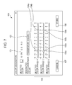
- Fig. 7 illustrates a color range setting screen for designating pixels to be color converted.
- RGB values 101 of the pixel P1 a user has selected on the display screen 50 are displayed.
- this display is not limited to such a display using the RGB values, and may be a display using L * a * b * values, or may be a display employing a different method.
- a setting portion 102 for setting a post-conversion color of pixels to be color converted is displayed.
- the setting portion 102 employs a pull-down method, and is configured such that an operation of clicking a button on the mouse device 30 under the state where the setting portion 102 is pointed by the pointer P enables selection of any one of "transparent color", "white color” and "designated color”.
- "designated color” is selected, a screen for inputting RGB values as a color of "designated color” is displayed, and a user can set any color as the color of "designated color”.
- "transparent color” is selected in this embodiment.
- selected color range designation portions 103 each for setting a color range of pixels to be color converted are displayed.
- the selected color range designation portions 103 are each displayed so as to be associated with a corresponding one of the three RGB colors.
- a user can set, for each of the RGB colors, a color range for pixels to be color converted by shifting, with the mouse device 30, a corresponding one of a pair of buttons (sliders) 104a and 104b, a pair of buttons (sliders) 105a and 105b and a pair of buttons (sliders) 106a and 106b.
- the selected color range designation portions 103 are configured so as to, when relative RGB values (that is, relative gray-scale levels) each associated with a corresponding one of the RGB values 101 of the pixel P1 are made "0", allow a user to determine, for each of the RGB colors, a minimum relative gray-scale level and a maximum relative gray-scale level of a color range for pixels to be color converted.
- the number of gray-scale levels is 256.
- a minimum relative gray-scale level of "-3" and a maximum relative gray-scale level of "+3" of a color range are set by using the button (slider) 104a and the button (slider) 104b, respectively.
- pixels each having a relative R value that is, a relative gray-scale level for an R color
- the R value of the pixel P1 is "128" so pixels each having an R value larger than or equal to "125” and smaller than or equal to "131" are selected.
- a minimum relative gray-scale level of "-3" and a maximum gray-scale level of "+3" of a color range are set by using the button (slider)105a and the button (slider) 105b, respectively, and similarly, in a selected color range B, a minimum relative gray-scale level of "-3" and a maximum gray-scale level of "+3" of a color range are set by using the lever 106a and the lever 106b, respectively.
- pixels each having an R value larger than or equal to "125” and smaller than or equal to "131", a G value larger than or equal to "0” and smaller than or equal to "3", and a B value larger than or equal to "0" and smaller than or equal to "3" are selected.
- the PC 21 sequentially determines whether or not a pixel constituting the image D corresponds to the above color range, until a pixel adjacent to a determination-completed pixel becomes a pixel not corresponding to the above color range. That is, the PC 21 has a role of the determination portion according to the first aspect of the invention, which determines whether or not a given pixel corresponds to the above color range, as well as a role of the determination practice portion according to the first aspect of the invention, which causes the determination portion to practice the above determination.
- pixels constituting a circular shaped image Ci in the image D correspond to the above color range, and thus, the pixels constituting the circular shaped image Ci are designated by the PC 21 which also has a role of the pixel designation portion according to the first aspect of the invention.
- a cancel button 107 for cancelling the above settings and a storage button 108 for storing the above settings are displayed on the color range setting screen 100.
- colors each associated with a corresponding one of the pixels constituting the circular shaped image Ci and having been designated by the PC 21 in such a way as described above are converted into a color having been set in the setting portion 102 by the PC 21 which also has a role of the color conversion portion according to the first aspect of the invention.
- the color having been set in the setting portion 102 is "transparent color", and thus, each piece of color data associated with a corresponding one of the pixels constituting the circular shaped image Ci is converted into a piece of data based on a color reflecting a color of the recording target medium M (that is, the piece of data indicating that recording is unnecessary).
- the PC 21, which also has a role of the recording data generation portion according to the first aspect of the invention, generates recording data on the basis of the image data having been color converted in such a way as described above.
- the recording system of this embodiment is configured so as to be capable of retrieving an image of the recording target medium M. Moreover, the recording system of this embodiment is capable of displaying this retrieved image on the monitor 31 as shown in Fig. 5 , and further, is also capable of displaying a template stored in the ROM 24 thereon.
- the ROM 24 has a role as the storage portion according to the third aspect of the invention, which stores therein pre-conversion colors each associated with a corresponding one of pixels which have been designated as pixels to be color converted by the PC 21.
- the PC 21 is capable of designating a post-conversion color of each of the designated pixels by varying a pre-conversion color of the each of the designated pixels such that an amount of the variation corresponds to an amount of a variation of a pre-conversion color which is associated with any one of the designated pixels and is stored in the ROM 24.
- an R value, a G value and a B value of a pre-conversion color of a first pixel of the designated pixels are “128", “0" and “0", respectively, and an R value, a G value and a B value of a post-conversion color of the first pixel are "128", "1" and 1", respectively.
- a data processing method for a color conversion of the designated pixels into a transparent color or a white color is different from that for a color conversion of the designated pixels into a designated color.
- recording in a specific color is performed with respect to a specific mark and the like.
- a data processing method different from that for recording in the transparent color or the white color is required. According to this embodiment, even in such a case, it is possible to deal with such a requirement without any trouble.
- the PC 21 of this embodiment When converting data corresponding to each of the designated pixels into data based on the transparent color or the white color, the PC 21 of this embodiment directly converts RGB data into CMYK data. Further, when converting data corresponding to each of the designated pixels into data based on the designated color, the PC 21 converts the RGB data into different RGB data, and then, converts the different RGB data into CMYK data.
- the PC 21 of this embodiment is also capable of selecting the pixels P2 falling within a given area when selecting pixels to be color converted. In this case, it is possible to set a color range on the basis of an average value of the pixels P2 falling within the given area. Moreover, the PC 21 of this embodiment is configured so as to be capable of further selecting a partial pixel from among pixels included in the color range having been set in such a way described above. Through setting a color range on the basis of the pixels having been selected in such a way as described above, it is possible to, particularly in image data including various colors in a narrow area, designate pixels to be targeted for designation for the purpose of a color conversion with further accuracy.
- Fig. 8A and Fig. 8B are diagrams each illustrating a color range setting screen for designating pixels to be color converted, according to another embodiment.
- a method for designating pixels to be color converted a method for setting a range on an RGB-value basis by using a screen shown in Fig. 8A or a method for visually setting a range by using a screen shown in Fig. 8B . It is possible to select any one of the method for setting a range on an RGB-value basis and the method for visually setting a range by using a selection portion 109, and further, it is possible to perform setting of a color range for pixels to be color converted by using the buttons (sliders) L, just like in the aforementioned embodiment.
- the aforementioned embodiment is an embodiment of the PC 21 functioning as a recording data generation apparatus, as well as a recording system including the PC 21 and the recording apparatus 1. Moreover, a program for allowing a computer such as the PC 21 to function just like in the aforementioned embodiment is also included in the invention.
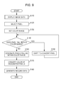
- Fig. 9 is a flowchart illustrating a recording data generation method according to an embodiment of the invention.
- the recording data generation method of this embodiment is an embodiment using the aforementioned recording system.
- step S110 image data for use in generation of recording data is displayed on the monitor 31.
- this display of image data is a display of image data corresponding to that shown in Fig. 5 or Fig. 6 , and is always performed during operations of individual steps described below.
- step S120 a partial pixel among pixels to be color converted is selected from among pixels constituting the image data displayed on the monitor 31.
- step S130 a user sets a color range on the basis of the partial pixel as a step for designating an area of pixels to be color converted.
- a screen which is displayed on the monitor 31 and is for use in the setting of the color range is just like the screen illustrated in Fig. 7 , Fig. 8A or Fig. 8B .
- step S140 it is determined whether or not a pixel constituting the image data is a pixel corresponding to the color range, and in the case where the relevant pixel is a pixel corresponding to the color range, the process flow proceeds to step S150, and after a pixel targeted for the above determination is shifted to a pixel (or pixels) adjacent to a determination-completed pixel, the process flow returns to step S140.
- the determination as to whether or not a pixel constituting the image data is a pixel corresponding to the color range is sequentially made on the basis of the partial pixel, until a pixel adjacent to a determination-completed pixel becomes a pixel not corresponding to the color range.
- This wording includes at least two different possibilities: either the process is repeated until one pixel adjacent a determination-completed falls outside the color range; or all pixels adjacent a determination-completed pixel are themselves determination-completed pixels or fall outside the color range. In this way, all pixels in a block of pixels falling within the color range can be selected.
- step S160 pixels, each having been determined as a pixel corresponding to the color range through the repetition of steps S140 and S150, are designated. That is, an area of pixels to be color converted is designated in this step.
- step S170 a color of each of the pixels having been designated in step S160 is converted into a desired color.
- step S180 recording data is generated on the basis of image data corresponding to the pixels having been color converted in step S170.
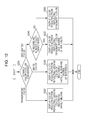
- Fig. 10 is a flowchart illustrating an image data display method according to an embodiment of the invention.
- the image data display method of this embodiment is an embodiment using the aforementioned recording system, and is an image data display method corresponding to step S110 of the above recording data generation method, which may be carried out continuously as the method shown in Fig. 9 is carried out.
- step S210 it is determined which one of a transparent color, a white color and a desired designated color a color of each of pixels to be color converted in step S170 of the above recording data generation method is set so as to be converted into.
- step S220 the process flow proceeds to step S220, and there, the pixels to be color converted are displayed on the monitor 31 such that the color of each of the pixels to be color converted reflects a ground color of the recording target medium M.
- step S230 the process flow proceeds to step S230, and there, the pixels to be color converted are displayed on the monitor 31 such that the color of each of the pixels to be color converted reflects a ground color of the recording target medium M and a degree of whiteness corresponding to a recording density of a white ink in recording in the white color.
- step S240 it is determined whether or not recording in the white color is to be further performed prior to recording in the desired designated color.
- step S250 the pixels to be color converted are displayed on the monitor 31 such that the color of each of the pixels to be color converted reflects a color of the designated color and a degree of whiteness corresponding to a recording density of a white ink in recording in the white color.
- step S260 the pixels to be color converted are displayed on the monitor 31 such that the color of each of the pixels to be color converted reflects a color of the designated color.
- step S260 the pixels to be color converted are displayed on the monitor 31 such that the color of each of the pixels to be color converted reflects a ground color of the recording target medium M and a color of the designated color under the state where a transmittance of the color of the designated color is set in advance.
- Figs. 11 to 14 are each an example of a display of image data.
- Fig. 11 is an example of a display of image data in a designated color
- Fig. 12 is an example of a display of image data in a white color
- Fig. 13 is an example of a display of image data in a designated color under the state where a transmittance of image data is set in advance
- Fig. 14 is an example of a display of image data in a different designated color.
- Fig. 11 is an example of a display of image data in a designated color.
- designated color RGB
- a color selection portion 110 When "designated color (RGB)" has been selected in a color selection portion 110, and each of an R value, a G value and a B value has been selected by using a corresponding one of buttons (sliders) L, areas designated by pointing a pointer P and performing clicking (in this case, the areas being a circular shaped image Ci and a character "J" of a character image Ch) are displayed in the designated color having been selected in the color selection portion 110.
- buttons (sliders) L buttons
- areas designated by pointing a pointer P and performing clicking in this case, the areas being a circular shaped image Ci and a character "J" of a character image Ch
- Fig. 12 is an example of a display of image data in a white color.
- a color selection portion 110 When "white ink setting" has been selected in a color selection portion 110, and "white color density” has been selected by using a button (slider) L, an area designated by pointing a pointer P and performing clicking, (in this case, the area being a quadrangular shaped image Q) is displayed with the white ink density having been selected in the color selection portion 110 (that is, the area is displayed in a color reflecting a ground color of the recording target medium M and a degree of whiteness corresponding to a recording density of a white ink in recording in the white color).
- Fig. 13 is an example of a display of image data in a designated color under the state where a transmittance of the image data is set in advance.
- a transmittance setting has been selected in a color selection portion 110
- "transmittance” has been selected by using a button (slider) L
- an area designated by pointing a pointer P and performing clicking is displayed with the transmittance having been selected in the color selection portion 110 (that is, the area is displayed in a color reflecting a ground color of the recording target medium M and the color of the designated color).
- Fig. 14 is a diagram illustrating an example of a display of image data in a designated color.
- (a) of Fig. 14 and (b) of Fig. 14 illustrate a pre-color-conversion image and a post-color-conversion image, respectively.
- a post-color-conversion image F shown in (b) of Fig. 14 , is displayed by performing color conversion of the pre-color-conversion image F, that is, by varying the stored pre-conversion color of each of the pixels constituting the pre-color-conversion image F such that an amount of the variation corresponds to an amount of a variation of a pre-conversion color which is associated with the pixels constituting the pre-color-conversion image F and is stored in the ROM 24.
Landscapes
- Engineering & Computer Science (AREA)
- Multimedia (AREA)
- Signal Processing (AREA)
- General Engineering & Computer Science (AREA)
- Physics & Mathematics (AREA)
- General Physics & Mathematics (AREA)
- Theoretical Computer Science (AREA)
- Color Image Communication Systems (AREA)
- Facsimile Image Signal Circuits (AREA)
- Image Processing (AREA)
Abstract
Description
- The present invention relates to a recording data generation apparatus, a recording system, a program, a recording data generation method and an image data display method.
- Heretofore, there have been utilized recording data generation apparatuses each generating recording data for use in recording operation of a recording apparatus on the basis image data. In such a recording data generation apparatus, processing for converting a specific color in image data into a different color has been frequently performed.
- For example, in
JP-A-63-46071 - Meanwhile, when converting a specific color within a desired area of image data, sometimes, it is not easy to select the specific color. For example, when converting only a specific color within a desired area of image data, if the desired area is hard to be designated with accuracy, the specific color in areas other than the desired area is likely to be converted. Further, when attempting to designate the inside of a desired area of image data with accuracy, there are some cases where the designation is difficult depending on the property of the image data.
- Nevertheless, the image processing method disclosed in
JP-A-63-46071 - An advantage of some aspects of the invention is to make it easy to, when converting a specific color within a desired area of image data into a different color, select the specific color.
- A recording data generation apparatus according to a first aspect of the invention, which generates recording data for use in recording operation of a recording apparatus on the basis of image data, includes a display portion that displays the image data; a selection portion that allows selection of a partial pixel from among pixels constituting the image data displayed on the display portion; a color range setting portion that allows setting a color range on the basis of a color of the partial pixel; a determination portion that determines whether or not a pixel constituting the image data is a pixel falling within the color range; a determination practice portion that causes the determination made by the determination portion to be sequentially practiced with respect to a pixel adjacent to a determination-completed pixel on the basis of the partial pixel until the pixel adjacent to a determination-completed pixel becomes a pixel not falling within the color range; a pixel designation portion that designates at least one pixel which is determined as a pixel falling within the color range by the determination portion; a color conversion portion that converts a color of each of the at least one pixel designated by the pixel designation portion; and a recording data generation portion that generates recording data on the basis of image data resulting from the color conversion by the color conversion portion with respect to a color of each of the at least one pixel designated by the pixel designation portion.
- Here, "allowing setting a color range on the basis of a color of the partial pixel" corresponds to a case where, for example, when a color of the partial pixel is represented by RGB values each being one of 256 gray-scale levels, the relevant color range can be set so as to cover, for each of RGB colors, a range having a desired amplitude relative to its center which is placed at a corresponding one of the RGB values representing the color of the partial pixel. In addition, besides such a configuration represented by RGB values, a different configuration represented by L * a * b * values or the like may be employed. In addition, "until the pixel adjacent to a determination-completed pixel becomes a pixel not falling within the color range" includes or can mean instead that the determination carried out by the determination portion continues until all pixels adjacent a determination-completed pixel either are also determination-completed pixels or do not fall within the color range.
- According to this aspect, through the selection of a partial pixel from among pixels included in a desired area of image data as well as the setting of a color range based on a color of the partial pixel, an area of pixels to be color converted can be made within the desired area on the basis of the partial pixel. Thus, it becomes easy to select pixels which are desired to be color converted. That is, it is possible to make it easy to, when converting a specific color in a desired area of image data, select the specific color. Further, it is possible to make it easy for the color conversion portion to convert a color of each of pixels included in a desired area into a desired color.
- A recording data generation apparatus according to a second aspect of the invention is configured such that, in the first aspect, the color conversion portion allows the conversion of a color of each of the at least one pixel designated by the pixel designation portion into any one of a transparent color, a white color and a designated color, and the recording data generation apparatus includes a color designation portion that allows designation of any color as a color of the designated color.
- According to this aspect, it is possible to easily convert a color of each of the pixels designated by the pixel designation portion into any one of three kinds of color, that is, the transparent color, the white color and the designated color. Further, it is possible to select any color as the designated color.
- A recording data generation apparatus according to a third aspect of the invention is configured such that, in the second aspect, a storage portion that stores therein a pre-conversion color of each of the at least one pixel designated by the pixel designation portion is further provided, and the color designation portion performs designation of a post-conversion color of each of the at least one pixel designated by the pixel designation portion by varying a pre-conversion color of the each of the at least one pixel such that an amount of the variation corresponds to an amount of a variation of a pre-conversion color which is associated with any one of the at least one pixel and is stored in the storage portion.
- According to this aspect, as a result, a variation between post-conversion colors of any two ones of the pixels corresponds to a variation between pre-conversion colors of the any two ones of the pixels. That is, the gradation of the selected pixels before a color conversion can be kept in the gradation of the selected pixels after the color conversion.
- A recording data generation apparatus according to a fourth aspect of the invention is configured such that, in the second aspect or the third aspect, the color conversion portion causes a data processing method for converting a color of each of the at least one pixel designated by the pixel designation portion into the transparent color or the white color to differ from a data processing method for converting the color of each of the at least one pixel designated by the pixel designation portion into the designated color.
- When recording in the designated color is performed, sometimes, irrespective of color matching or the like, a specific mark or the like is recorded in a specific color. Thus, there are some cases where a data processing method different from that for recording in the transparent color or the white color is required. According to this aspect, it is possible to deal with such a requirement without any trouble.
- That is, it is possible to deal with such a requirement by, for example, employing a process in which, when data corresponding to each of the designated pixels is converted into data based on the transparent color or the white color, RGB data is directly converted into CMYK data, and when data corresponding to each of the designated pixels is converted into data based on the designated color, RGB data is converted into different RGB data, and then, the different RGB data is converted into CMYK data.
- A recording data generation apparatus according to a fifth aspect of the invention is configured such that, in any one of the first to fourth aspects, the selection portion allows selection of a plurality of pixels from among the pixels constituting the image data, and the color range setting portion allows setting a color range on the basis of an average value of colors each associated with a corresponding one of the plurality of pixels.
- According to this aspect, it is possible to set a color range on the basis of an average value of colors each associated with a corresponding one of a plurality of pixels. Thus, in the case where colors each associated with a corresponding one of pixels to be targeted for designation by the pixel designation portion are not uniform, it becomes possible to designate the pixels to be targeted for designation more accurately because an average value of colors each associated with a corresponding one of the plurality of pixels among the pixels to be targeted for designation can be made a basis of the designation.
- A recording data generation apparatus according to a sixth aspect of the invention is configured such that, in the fifth aspect, the selection portion allows further selection of a partial pixel from at least one pixel included in the color range set by using the color range setting portion.
- According to this aspect, it becomes possible to designate pixels to be targeted for destination more accurately than in the fifth aspect, particularly in image data including various colors in a narrow area.
- A recording system according to a seventh aspect of the invention includes the recording data generation apparatus according to any one of the first to sixth aspects; and a recording apparatus that performs recording on the basis of recording data generated by the recording data generation apparatus.
- According to this aspect, it is possible to make it easy to, when converting a specific color in a desired area of image data, select the specific color. Further, it is possible to easily convert a color of each of pixels included in a desired area into a desired color and perform recording.
- A program according to an eight aspect of the invention, which generates recording data for use in recording operation of a recording apparatus on the basis of image data, causes a computer to function as an apparatus including the portions of a display portion that displays the image data; a selection portion that allows selection of a partial pixel from among pixels constituting the image data displayed on the display portion; a color range setting portion that allows setting a color range on the basis of a color of the partial pixel; a determination portion that determines whether or not a pixel constituting the image data is a pixel falling within the color range; a determination practice portion that causes the determination made by the determination portion to be sequentially practiced with respect to a pixel adjacent to a determination-completed pixel on the basis of the partial pixel until the pixel adjacent to a determination-completed pixel becomes a pixel not falling within the color range; a pixel designation portion that designates at least one pixel which is determined as a pixel falling within the color range by the determination portion; a color conversion portion that converts a color of each of the at least one pixel designated by the pixel designation portion; and a recording data generation portion that generates recording data on the basis of image data resulting from the color conversion by the color conversion portion with respect to a color of each of the at least one pixel designated by the pixel designation portion.
- According to this aspect, it is possible to make it easy to, when converting a specific color in a desired area of image data, select the specific color. Further, it is possible to make it easy to convert a color of each of pixels included in a desired area into a desired color.
- A recording data generation method according to a ninth aspect of the invention, which is used for generating recording data for use in recording operation of a recording apparatus on the basis of image data, includes a display process of displaying the image data; a selection process of selecting a partial pixel from among pixels constituting the image data displayed on the display portion; a color range setting process of setting a color range on the basis of a color of the partial pixel; a determination practice process of causing a determination process of determining whether or not a pixel included in the pixels constituting the image data is a pixel falling within the color range to be sequentially practiced with respect to a pixel adjacent to a previously determined pixel on the basis of the partial pixel until the pixel adjacent to a previously determined pixel becomes a pixel not falling within the color range; a pixel designation process of designating at least one pixel which is determined to be a pixel falling within the color range by the determination process; a color conversion process of converting a color of each of the at least one pixel designated by the pixel designation process; a recording data generation process of generating recording data on the basis of image data resulting from the color conversion by the color conversion process with respect to a color of each of the at least one pixel designated by the pixel designation process.
- According to this aspect, it is possible to make it easy to, when converting a specific color in a desired area of image data, select the specific color. Further, it is possible to make it easy to convert a color of each of pixels included in a desired area into a desired color.
- An image data display method according to a tenth aspect of the invention, which is for use in the recording data generation apparatus according to any one of the aspects from the second aspect to the sixth aspect, includes displaying the image data on the display portion such that a color of the image data reflects a ground color of a recording target medium in the case where a color of each of the at least one pixel designated by the pixel designation portion is converted into the transparent color; displaying the image data on the display portion such that a color of the image data reflects a ground color of a recording target medium and a degree of whiteness corresponding to a recording density of a white ink in recording in a white color in the case where a color of each of the at least one pixel designated by the pixel designation portion is converted into the white color; displaying the image data on the display portion such that a color of the image data reflects a color of the designated color and a degree of whiteness corresponding to a recording density of a white ink in recording in a white color in the case where a color of each of the at least one pixel designated by the pixel designation portion is converted into the designated color and recording in a white color is performed; and displaying the image data on the display portion such that a color of the image data reflects a color of the designated color in the case where a color of each of the at least one pixel designated by the pixel designation portion is converted into the designated color and recording in a white color is not performed.
- According to this aspect, it becomes possible to display an image in the state close to a recording image actually recorded on a recording target medium.
- Embodiments of the invention will now be described by way of example only with reference to the accompanying drawings, wherein like numbers reference like elements.
-
Fig. 1 is an overview perspective view illustrating a recording apparatus constituting a recording system according to an embodiment of the invention. -
Fig. 2 is an overview plan view illustrating a recording apparatus constituting a recording system according to an embodiment of the invention. -
Fig. 3 is a block diagram illustrating a recording system according to an embodiment of the invention. -
Fig. 4 is a block diagram illustrating a PC constituting a recording system according to an embodiment of the invention. -
Fig. 5 is a diagram illustrating a display screen for use in selection of a partial pixel from among pixels constituting image data displayed on a monitor, according an embodiment of the invention. -
Fig. 6 is a diagram illustrating a display screen for use in selection of pixels included in a partial area from among pixels constituting image data displayed on a monitor, according an embodiment of the invention. -
Fig. 7 is a diagram illustrating a color range setting screen for use in designation of pixels to be color converted, according to an embodiment of the invention. -
Fig. 8A and Fig. 8B are diagrams each illustrating a color range setting screen for use in designation of pixels to be color converted, according to an embodiment of the invention. -
Fig. 9 is a flowchart illustrating a recording data generation method according to an embodiment of the invention. -
Fig. 10 is a flowchart illustrating an image data display method according to an embodiment of the invention. -
Fig. 11 is an example of a display of image data in a designated color, according to an embodiment of the invention. -
Fig. 12 is an example of a display of image data in a white color, according to an embodiment of the invention. -
Fig. 13 is an example of a display of image data in a designated color under the state where a transmittance of the image data is set in advance, according to an embodiment of the invention. -
Fig. 14 is an example of a display of image data in a designated color, according to an embodiment of the invention. - Hereinafter, a recording data generation apparatus and a recording system according to an embodiment of the invention will be described in detail with reference to the accompanying drawings.
- First, a recording apparatus constituting a recording system according to an embodiment of the invention will be described.
-
Fig. 1 andFig. 2 illustrate an overview perspective view and an overview plan view of arecording apparatus 1 according to an embodiment of the invention, respectively. In addition, therecording apparatus 1 of this embodiment is a recording apparatus configured so as to be capable of performing recording on a fabric as a recording target medium M (refer toFig. 5 ), but is not limited to any recording apparatus configured in such a way. - The
recording apparatus 1 of this embodiment includes amedium supporting tray 2 for supporting a fabric as the recording target medium M. Further, therecording apparatus 1 includes amovement mechanism 3 for transporting the recording target medium M supported by themedium supporting tray 2 in a transportation direction A. In addition, themovement mechanism 3 of this embodiment is configured so as to move the medium supporting tray 2 (that is, so as to transport the recording target medium M supported by the medium supporting tray 2) relative to a recording head 6 (refer toFig. 3 ). Nevertheless, themovement mechanism 3 of this embodiment may be configured so as to move therecording head 6 relative to themedium supporting tray 2 or cause the both to perform relative movement. - Further, the
medium supporting tray 2 is supported by astage 4. Themedium supporting tray 2 moves in a height direction C together with thestage 4 in conjunction with the rotation of arotation lever 5. - Further, the
recording head 6 is installed inside the body of therecording apparatus 1. Further, therecording apparatus 1 of this embodiment forms images based on recording data by ejecting inks from therecording head 6 onto the recording target medium M which is transported being supported by themedium supporting tray 2, while reciprocating therecording head 6 in a scanning direction B intersecting with the transportation direction A. In addition, in therecording apparatus 1 of this embodiment, a position at which the recording target medium M is set on themedium supporting tray 2 is located at a front side of the recording apparatus 1 (a left lower portion ofFig. 1 ), and a recording start position is located at a back side of the recording apparatus 1 (a right upper portion ofFig. 1 ). After having moved themedium supporting tray 2 to the recording start position, therecording apparatus 1 starts recording and continues the recording while moving themedium supporting tray 2 in a direction towards the front side of therecording apparatus 1. - Further, the
recording apparatus 1 includes amonitor 8 and acontrol panel 9. After having selected desired setting items on menus displayed on themonitor 8 while manipulating thecontrol panel 9, a user can actuate therecording apparatus 1 in accordance with the selected setting items. For example, after having selected a kind of the recording target medium M to be used in subsequent recording, recording modes in the transportation direction A and the scanning direction B, and the like, a user can actuate therecording apparatus 1 in accordance with the selected setting items. - In addition, the
recording apparatus 1 includes ink cartridges (not illustrated) each containing a corresponding one of a white ink, a black ink, a cyan ink, a magenta ink and a yellow ink. - Next, an electrical configuration of the
recording apparatus 1 of this embodiment will be described. -
Fig. 3 is a block diagram of therecording apparatus 1 of this embodiment. - A
control unit 10 includes aCPU 11 for performing control of the whole of therecording apparatus 1. TheCPU 11 is electrically connected, via asystem bus 12, to aROM 13 which stores therein various control programs carried out by theCPU 11, maintenance sequences and the like, and aRAM 14 which is capable of storing data therein temporarily. Further, theCPU 11 is electrically connected to, via thesystem bus 12, ahead driving unit 15 for driving therecording head 6. Further, theCPU 11 is electrically connected to, via thesystem bus 12, to amotor driving unit 18 which drives acarriage motor 16 for moving a carriage on which therecording head 6 is mounted, and which drives atransportation motor 17 for transporting the recording target medium M. Moreover, theCPU 11 is electrically connected to, via thesystem bus 12, an input andoutput unit 19 for transmitting and receiving data and signals to/from themonitor 8, thecontrol panel 9 and aninterface 20 for performing reception of recording data, and the like, from aPC 21 constituting a recording system of this embodiment, and functioning as a recording data generation apparatus in the recording system. - Next, the
PC 21 constituting a recording system of this embodiment and functioning as a recording data generation apparatus in the recording system will be described. -
Fig. 4 is a block diagram illustrating an electrical configuration of thePC 21 of this embodiment. - The
PC 21 includes aCPU 22 for performing control of the whole of thePC 21. TheCPU 22 is electrically connected to, via asystem bus 23, aROM 24 for storing therein various programs carried out by theCPU 22, and the like, aRAM 25 which is capable of storing data therein temporarily, and aHDD 26 which is a data storage device. Further, theCPU 22 is electrically connected to, via thesystem bus 23, a CD-ROM drive 28 which is capable of reading data from a CD-ROM 27 functioning as a data storage medium and being inserted in the CD-ROM drive 28. Moreover, theCPU 22 is electrically connected to, via thesystem bus 23, an input andoutput unit 33 for transmitting and receiving data and signals to/from akeyboard 29, amouse device 30, amonitor 31, and aninterface 32 for outputting recording data, and the like, to therecording apparatus 1. - The
PC 21 is capable of generating recording data for use in recording operation of therecording apparatus 1 on the basis of image data. Themonitor 31 has a role as the display portion for image data, according to the first aspect of the invention. Further, a user can select a partial pixel from among pixels constituting image data displayed on themonitor 31 by using thekeyboard 29 and themouse device 30. That is, thekeyboard 29 and themouse device 30 each have a role as the selection portion according to the first aspect of the invention.Fig. 5 illustrates adisplay screen 50 which is used when selecting a partial pixel from pixels constituting image data displayed on themonitor 31. - An image D based on image data is displayed inside an area R which is included in the recording target medium M (a T-shirt) and which is supported by the
medium supporting tray 2.Fig. 5 illustrates a state where a user has selected a partial pixel P1 from among pixels constituting the image D displayed on themonitor 31 by shifting a pointer P to a desired position with themouse device 30 and clicking a not-illustrated button on themouse device 30. In addition, as shown inFig. 6 , a user can also select pixels P2 falling within a given area by shifting the pointer P in an arrow direction denoted by a slotted line shown inFig. 6 while keeping the button of themouse device 30 in a pushed down state. In this case, a color range setting portion described below is capable of setting a color range on the basis of an average value of the pixels P2 falling within the given area. - Further, a user can set a color range for the image data displayed on the
monitor 21 on the basis of the partial pixel P1 by using thekeyboard 29 and themouse device 30. That is, themonitor 31, thekeyboard 29 and themouse device 30 each have a role of the color range setting portion according to the first aspect of the invention.Fig. 7 illustrates a color range setting screen for designating pixels to be color converted. - On a color
range setting screen 100, RGB values 101 of the pixel P1 a user has selected on thedisplay screen 50 are displayed. In addition, this display is not limited to such a display using the RGB values, and may be a display using L * a * b * values, or may be a display employing a different method. - Further, a setting
portion 102 for setting a post-conversion color of pixels to be color converted is displayed. The settingportion 102 employs a pull-down method, and is configured such that an operation of clicking a button on themouse device 30 under the state where the settingportion 102 is pointed by the pointer P enables selection of any one of "transparent color", "white color" and "designated color". Here, when "designated color" is selected, a screen for inputting RGB values as a color of "designated color" is displayed, and a user can set any color as the color of "designated color". In addition, "transparent color" is selected in this embodiment. - Further, selected color
range designation portions 103 each for setting a color range of pixels to be color converted are displayed. The selected colorrange designation portions 103 are each displayed so as to be associated with a corresponding one of the three RGB colors. A user can set, for each of the RGB colors, a color range for pixels to be color converted by shifting, with themouse device 30, a corresponding one of a pair of buttons (sliders) 104a and 104b, a pair of buttons (sliders) 105a and 105b and a pair of buttons (sliders) 106a and 106b. Namely, the selected colorrange designation portions 103 are configured so as to, when relative RGB values (that is, relative gray-scale levels) each associated with a corresponding one of the RGB values 101 of the pixel P1 are made "0", allow a user to determine, for each of the RGB colors, a minimum relative gray-scale level and a maximum relative gray-scale level of a color range for pixels to be color converted. In addition, in this embodiment, the number of gray-scale levels is 256. - For example, in a selected color range R, a minimum relative gray-scale level of "-3" and a maximum relative gray-scale level of "+3" of a color range are set by using the button (slider) 104a and the button (slider) 104b, respectively. This means that pixels each having a relative R value (that is, a relative gray-scale level for an R color) larger than or equal to "-3" and smaller than or equal to "+3" relative to the R value in the RGB values 101 of the pixel P1 can be selected. In
Fig. 7 , the R value of the pixel P1 is "128" so pixels each having an R value larger than or equal to "125" and smaller than or equal to "131" are selected. - Meanwhile, in a selected color range G, a minimum relative gray-scale level of "-3" and a maximum gray-scale level of "+3" of a color range are set by using the button (slider)105a and the button (slider) 105b, respectively, and similarly, in a selected color range B, a minimum relative gray-scale level of "-3" and a maximum gray-scale level of "+3" of a color range are set by using the
lever 106a and thelever 106b, respectively. Nevertheless, this means that, since a G value and a B value in theRGB value 101 of the pixel P1 are each "0", even though the minimum relative gray-scale level of "-3" and the maximum gray-scale level of "+3" of a color range are set, pixels each having a G value and a B value each larger than or equal to "0" and smaller than or equal to "3" can be selected. - In such a way as described above, in this embodiment, pixels each having an R value larger than or equal to "125" and smaller than or equal to "131", a G value larger than or equal to "0" and smaller than or equal to "3", and a B value larger than or equal to "0" and smaller than or equal to "3" are selected.
- On the basis of this setting, the
PC 21 sequentially determines whether or not a pixel constituting the image D corresponds to the above color range, until a pixel adjacent to a determination-completed pixel becomes a pixel not corresponding to the above color range. That is, thePC 21 has a role of the determination portion according to the first aspect of the invention, which determines whether or not a given pixel corresponds to the above color range, as well as a role of the determination practice portion according to the first aspect of the invention, which causes the determination portion to practice the above determination. Further, in this embodiment, pixels constituting a circular shaped image Ci in the image D correspond to the above color range, and thus, the pixels constituting the circular shaped image Ci are designated by thePC 21 which also has a role of the pixel designation portion according to the first aspect of the invention. - In addition, a cancel
button 107 for cancelling the above settings and astorage button 108 for storing the above settings are displayed on the colorrange setting screen 100. - Further, colors each associated with a corresponding one of the pixels constituting the circular shaped image Ci and having been designated by the
PC 21 in such a way as described above are converted into a color having been set in the settingportion 102 by thePC 21 which also has a role of the color conversion portion according to the first aspect of the invention. In this embodiment, the color having been set in the settingportion 102 is "transparent color", and thus, each piece of color data associated with a corresponding one of the pixels constituting the circular shaped image Ci is converted into a piece of data based on a color reflecting a color of the recording target medium M (that is, the piece of data indicating that recording is unnecessary). - Further, the
PC 21, which also has a role of the recording data generation portion according to the first aspect of the invention, generates recording data on the basis of the image data having been color converted in such a way as described above. - In addition, the recording system of this embodiment is configured so as to be capable of retrieving an image of the recording target medium M. Moreover, the recording system of this embodiment is capable of displaying this retrieved image on the
monitor 31 as shown inFig. 5 , and further, is also capable of displaying a template stored in theROM 24 thereon. - Further, in this embodiment, the
ROM 24 has a role as the storage portion according to the third aspect of the invention, which stores therein pre-conversion colors each associated with a corresponding one of pixels which have been designated as pixels to be color converted by thePC 21. ThePC 21 is capable of designating a post-conversion color of each of the designated pixels by varying a pre-conversion color of the each of the designated pixels such that an amount of the variation corresponds to an amount of a variation of a pre-conversion color which is associated with any one of the designated pixels and is stored in theROM 24. For example, it is assumed here that an R value, a G value and a B value of a pre-conversion color of a first pixel of the designated pixels are "128", "0" and "0", respectively, and an R value, a G value and a B value of a post-conversion color of the first pixel are "128", "1" and 1", respectively. In this case, when an R value, a G value and a B value of a pre-conversion color of a second pixel of the designated pixels are "127", "0" and "0", respectively, it is possible to perform a color conversion of the second pixel such that an R value, a G value and a B value of a post-conversion color of the second pixel become "127", "1" and "1", respectively. - Further, in the
PC 21 of this embodiment, a data processing method for a color conversion of the designated pixels into a transparent color or a white color is different from that for a color conversion of the designated pixels into a designated color. When performing recording in the designated color, sometimes, irrespective of color matching and the like, recording in a specific color is performed with respect to a specific mark and the like. Thus, there are some cases where a data processing method different from that for recording in the transparent color or the white color is required. According to this embodiment, even in such a case, it is possible to deal with such a requirement without any trouble. - When converting data corresponding to each of the designated pixels into data based on the transparent color or the white color, the
PC 21 of this embodiment directly converts RGB data into CMYK data. Further, when converting data corresponding to each of the designated pixels into data based on the designated color, thePC 21 converts the RGB data into different RGB data, and then, converts the different RGB data into CMYK data. - Further, as shown in
Fig. 6 thePC 21 of this embodiment is also capable of selecting the pixels P2 falling within a given area when selecting pixels to be color converted. In this case, it is possible to set a color range on the basis of an average value of the pixels P2 falling within the given area. Moreover, thePC 21 of this embodiment is configured so as to be capable of further selecting a partial pixel from among pixels included in the color range having been set in such a way described above. Through setting a color range on the basis of the pixels having been selected in such a way as described above, it is possible to, particularly in image data including various colors in a narrow area, designate pixels to be targeted for designation for the purpose of a color conversion with further accuracy. -
Fig. 8A and Fig. 8B are diagrams each illustrating a color range setting screen for designating pixels to be color converted, according to another embodiment. - In this embodiment, it is possible to select, as a method for designating pixels to be color converted, a method for setting a range on an RGB-value basis by using a screen shown in
Fig. 8A or a method for visually setting a range by using a screen shown inFig. 8B . It is possible to select any one of the method for setting a range on an RGB-value basis and the method for visually setting a range by using aselection portion 109, and further, it is possible to perform setting of a color range for pixels to be color converted by using the buttons (sliders) L, just like in the aforementioned embodiment. - The aforementioned embodiment is an embodiment of the
PC 21 functioning as a recording data generation apparatus, as well as a recording system including thePC 21 and therecording apparatus 1. Moreover, a program for allowing a computer such as thePC 21 to function just like in the aforementioned embodiment is also included in the invention. - Next, an embodiment of a recording data generation method according to an aspect of the invention will be described.
-
Fig. 9 is a flowchart illustrating a recording data generation method according to an embodiment of the invention. - In addition, the recording data generation method of this embodiment is an embodiment using the aforementioned recording system.
- In the recording data generation method of this embodiment, in step S110, image data for use in generation of recording data is displayed on the
monitor 31. In addition, this display of image data is a display of image data corresponding to that shown inFig. 5 orFig. 6 , and is always performed during operations of individual steps described below. - Next, in step S120, a partial pixel among pixels to be color converted is selected from among pixels constituting the image data displayed on the
monitor 31. - Next, in step S130, a user sets a color range on the basis of the partial pixel as a step for designating an area of pixels to be color converted. A screen which is displayed on the
monitor 31 and is for use in the setting of the color range is just like the screen illustrated inFig. 7 ,Fig. 8A or Fig. 8B . - Next, in step S140, it is determined whether or not a pixel constituting the image data is a pixel corresponding to the color range, and in the case where the relevant pixel is a pixel corresponding to the color range, the process flow proceeds to step S150, and after a pixel targeted for the above determination is shifted to a pixel (or pixels) adjacent to a determination-completed pixel, the process flow returns to step S140.
- That is, through the repetition of steps S140 and S150, the determination as to whether or not a pixel constituting the image data is a pixel corresponding to the color range is sequentially made on the basis of the partial pixel, until a pixel adjacent to a determination-completed pixel becomes a pixel not corresponding to the color range. This wording includes at least two different possibilities: either the process is repeated until one pixel adjacent a determination-completed falls outside the color range; or all pixels adjacent a determination-completed pixel are themselves determination-completed pixels or fall outside the color range. In this way, all pixels in a block of pixels falling within the color range can be selected.
- Next, in step S160, pixels, each having been determined as a pixel corresponding to the color range through the repetition of steps S140 and S150, are designated. That is, an area of pixels to be color converted is designated in this step.
- Next, in step S170, a color of each of the pixels having been designated in step S160 is converted into a desired color. In addition, in this embodiment, it is possible to perform conversion into any one of the transparent color, the white color and the designated color.
- Next, in step S180, recording data is generated on the basis of image data corresponding to the pixels having been color converted in step S170.
- Next, an embodiment of an image data display method according to an aspect of the invention will be described.
-
Fig. 10 is a flowchart illustrating an image data display method according to an embodiment of the invention. - In addition, the image data display method of this embodiment is an embodiment using the aforementioned recording system, and is an image data display method corresponding to step S110 of the above recording data generation method, which may be carried out continuously as the method shown in
Fig. 9 is carried out. - In the image data display method of this embodiment, in step S210, it is determined which one of a transparent color, a white color and a desired designated color a color of each of pixels to be color converted in step S170 of the above recording data generation method is set so as to be converted into.
- In the case where the color of each of pixels to be color converted is set so as to be converted into the transparent color, the process flow proceeds to step S220, and there, the pixels to be color converted are displayed on the
monitor 31 such that the color of each of the pixels to be color converted reflects a ground color of the recording target medium M. - In the case where the color of each of the pixels to be color converted is set so as to be converted into the white color, the process flow proceeds to step S230, and there, the pixels to be color converted are displayed on the
monitor 31 such that the color of each of the pixels to be color converted reflects a ground color of the recording target medium M and a degree of whiteness corresponding to a recording density of a white ink in recording in the white color. - In the case where the color of each pixels to be color converted is set so as to be converted into the desired designated color, the process flow proceeds to step S240, and there, it is determined whether or not recording in the white color is to be further performed prior to recording in the desired designated color.
- In the case where further recording in the white color is performed, in step S250, the pixels to be color converted are displayed on the
monitor 31 such that the color of each of the pixels to be color converted reflects a color of the designated color and a degree of whiteness corresponding to a recording density of a white ink in recording in the white color. - In the case where the further recording in the white color is not performed, in step S260, the pixels to be color converted are displayed on the
monitor 31 such that the color of each of the pixels to be color converted reflects a color of the designated color. In addition, in step S260, the pixels to be color converted are displayed on themonitor 31 such that the color of each of the pixels to be color converted reflects a ground color of the recording target medium M and a color of the designated color under the state where a transmittance of the color of the designated color is set in advance. -
Figs. 11 to 14 are each an example of a display of image data.Fig. 11 is an example of a display of image data in a designated color;Fig. 12 is an example of a display of image data in a white color;Fig. 13 is an example of a display of image data in a designated color under the state where a transmittance of image data is set in advance; andFig. 14 is an example of a display of image data in a different designated color. -
Fig. 11 is an example of a display of image data in a designated color. When "designated color (RGB)" has been selected in acolor selection portion 110, and each of an R value, a G value and a B value has been selected by using a corresponding one of buttons (sliders) L, areas designated by pointing a pointer P and performing clicking (in this case, the areas being a circular shaped image Ci and a character "J" of a character image Ch) are displayed in the designated color having been selected in thecolor selection portion 110. -
Fig. 12 is an example of a display of image data in a white color. When "white ink setting" has been selected in acolor selection portion 110, and "white color density" has been selected by using a button (slider) L, an area designated by pointing a pointer P and performing clicking, (in this case, the area being a quadrangular shaped image Q) is displayed with the white ink density having been selected in the color selection portion 110 (that is, the area is displayed in a color reflecting a ground color of the recording target medium M and a degree of whiteness corresponding to a recording density of a white ink in recording in the white color). -
Fig. 13 is an example of a display of image data in a designated color under the state where a transmittance of the image data is set in advance. When "transmittance setting" has been selected in acolor selection portion 110, and "transmittance" has been selected by using a button (slider) L, an area designated by pointing a pointer P and performing clicking (in this case, the area being a circular shaped image Ci) is displayed with the transmittance having been selected in the color selection portion 110 (that is, the area is displayed in a color reflecting a ground color of the recording target medium M and the color of the designated color). -
Fig. 14 is a diagram illustrating an example of a display of image data in a designated color. In addition,(a) of Fig. 14 and (b) of Fig. 14 illustrate a pre-color-conversion image and a post-color-conversion image, respectively. When "designated color (RGB)" has been selected in acolor selection portion 110, and each of an R value, a G value and a B value has been selected by using a corresponding one of buttons (sliders) L, an area designated by pointing a pointer P and performing clicking (in this case, the area being a flower image F) is displayed in the color having been selected in thecolor selection portion 110 under the state where the gradation of the pre-color-conversion image is kept in the gradation of the post-color-conversion image. That is, a pre-conversion color of each of pixels constituting a pre-color-conversion image F, shown in (a) ofFig. 14 , is stored in theROM 24, and a post-color-conversion image F, shown in (b) ofFig. 14 , is displayed by performing color conversion of the pre-color-conversion image F, that is, by varying the stored pre-conversion color of each of the pixels constituting the pre-color-conversion image F such that an amount of the variation corresponds to an amount of a variation of a pre-conversion color which is associated with the pixels constituting the pre-color-conversion image F and is stored in theROM 24. - The foregoing description has been given by way of example only and it will be appreciated by a person skilled in the art that modifications can be made without departing from the scope of the present invention.
Claims (10)
- A recording data generation apparatus (21) that is adapted to generate recording data for use in recording operation of a recording apparatus (1) on the basis of image data, the recording data generation apparatus comprising:a display portion (31) that is adapted to display the image data;a selection portion that is adapted to allow selection of a partial pixel (P1) from among pixels constituting the image data displayed on the display portion;a color range setting portion that is adapted to allow setting a color range on the basis of a color of the partial pixel;a determination portion that is adapted to determine whether or not a pixel constituting the image data is a pixel falling within the color range;a determination practice portion that is adapted to cause the determination made by the determination portion to be sequentially practiced with respect to a pixel adjacent to a determination-completed pixel on the basis of the partial pixel until the pixel adjacent to a determination-completed pixel becomes a pixel not falling within the color range;a pixel designation portion that is adapted to designate at least one pixel which is determined as a pixel falling within the color range by the determination portion;a color conversion portion that is adapted to convert a color pixel designated by the pixel designation portion; anda recording data generation portion that is adapted to generate recording data on the basis of image data resulting from the color conversion by the color conversion portion with respect to a color of each of the at least one pixel designated by the pixel designation portion.
- The recording data generation apparatus according to Claim 1, wherein the color conversion portion that is adapted to allow the conversion of a color pixel designated by the pixel designation portion into any one of a transparent color, a white color and a designated color, and the recording data generation apparatus includes a color designation portion that is adapted to allow designation of any color as a color of the designated color.
- The recording data generation apparatus according to Claim 2, further comprising a storage portion that is adapted to store therein a pre-conversion color of each pixel designated by the pixel designation portion,
wherein the color designation portion is adapted to perform designation of a post-conversion color of each pixel designated by the pixel designation portion by varying a pre-conversion color of each designated pixel such that an amount of variation of post-conversion color corresponds to an amount of variation of pre-conversion color which is associated with the designated pixels and is stored in the storage portion. - The recording data generation apparatus according to Claim 2 or Claim 3, wherein the color conversion portion is adapted to cause a data processing method for converting a color of each pixel designated by the pixel designation portion into the transparent color or the white color to differ from a data processing method for converting the color of each of the at least one pixel designated by the pixel designation portion into the designated color.
- The recording data generation apparatus according to any one of the preceding claims, wherein the selection portion is adapted to allow selection of a plurality of pixels from among the pixels constituting the image data, and the color range setting portion allows setting a color range on the basis of an average value of colors each associated with a corresponding one of the plurality of pixels.
- The recording data generation apparatus according to Claim 5, wherein the selection portion is adapted to allow further selection of a partial pixel from at least one pixel included in the color range set by using the color range setting portion.
- A recording system comprising:the recording data generation apparatus according to any one of the preceding claims; anda recording apparatus (1) that is adapted to perform recording on the basis of recording data generated by the recording data generation apparatus.
- A program for generating recording data for use in recording operation of a recording apparatus (1) on the basis of image data, the program causing a computer to function as an apparatus comprising the portions of:a display portion that displays the image data;a selection portion that allows selection of a partial pixel from among pixels constituting the image data displayed on the display portion;a color range setting portion that allows setting a color range on the basis of a color of the partial pixel;a determination portion that determines whether or not a pixel constituting the image data is a pixel falling within the color range;a determination practice portion that causes the determination made by the determination portion to be sequentially practiced with respect to a pixel adjacent to a determination-completed pixel on the basis of the partial pixel until the pixel adjacent to a determination-completed pixel becomes a pixel not falling within the color range;a pixel designation portion that designates at least one pixel which is determined as a pixel falling within the color range by the determination portion;a color conversion portion that converts a color of each pixel designated by the pixel designation portion; anda recording data generation portion that generates recording data on the basis of image data resulting from the color conversion by the color conversion portion with respect to a color of each pixel designated by the pixel designation portion.
- A recording data generation method for generating recording data for use in recording operation of a recording apparatus (1) on the basis of image data, the recording data generation method comprising:a display process of displaying the image data;a selection process of selecting a partial pixel from among pixels constituting the image data displayed on the display portion;a color range setting process of setting a color range on the basis of a color of the partial pixel;a determination practice process of causing a determination process of determining whether or not a pixel included in the pixels constituting the image data is a pixel falling within the color range to be sequentially practiced with respect to a pixel adjacent to a determination-completed pixel on the basis of the partial pixel until the pixel adjacent to a determination-completed pixel becomes a pixel not falling within the color range;a pixel designation process of designating at least one pixel which is determined as a pixel falling within the color range by the determination process;a color conversion process of converting a color of each pixel designated by the pixel designation process; anda recording data generation process of generating recording data on the basis of image data resulting from the color conversion by the color conversion process with respect to a color of each pixel designated by the pixel designation process.
- An image data display method for use in the recording data generation apparatus according to Claim 2, the image data display method comprising:displaying the image data on the display portion such that a color of the image data reflects a ground color of a recording target medium in the case where a color of each pixel designated by the pixel designation portion is converted into the transparent color;displaying the image data on the display portion such that a color of the image data reflects a ground color of a recording target medium and a degree of whiteness corresponding to a recording density of a white ink in recording in a white color in the case where a color of each pixel designated by the pixel designation portion is converted into the white color;displaying the image data on the display portion such that a color of the image data reflects a color of the designated color and a degree of whiteness corresponding to a recording density of a white ink in recording in a white color in the case where a color of each pixel designated by the pixel designation portion is converted into the designated color and recording in a white color is performed; anddisplaying the image data on the display portion such that a color of the image data reflects a color of the designated color in the case where a color of each pixel designated by the pixel designation portion is converted into the designated color and recording in a white color is not performed.
Applications Claiming Priority (1)
| Application Number | Priority Date | Filing Date | Title |
|---|---|---|---|
| JP2012270143A JP6048655B2 (en) | 2012-12-11 | 2012-12-11 | RECORDING DATA GENERATION DEVICE, RECORDING SYSTEM, PROGRAM, RECORDING DATA GENERATION METHOD, AND IMAGE DATA DISPLAY METHOD |
Publications (3)
| Publication Number | Publication Date |
|---|---|
| EP2744188A2 true EP2744188A2 (en) | 2014-06-18 |
| EP2744188A3 EP2744188A3 (en) | 2016-04-06 |
| EP2744188B1 EP2744188B1 (en) | 2021-03-10 |
Family
ID=49765846
Family Applications (1)
| Application Number | Title | Priority Date | Filing Date |
|---|---|---|---|
| EP13196649.1A Active EP2744188B1 (en) | 2012-12-11 | 2013-12-11 | Recording data generation apparatus, recording system, program, recording data generation method and image data display method |
Country Status (3)
| Country | Link |
|---|---|
| US (2) | US9019559B2 (en) |
| EP (1) | EP2744188B1 (en) |
| JP (1) | JP6048655B2 (en) |
Families Citing this family (4)
| Publication number | Priority date | Publication date | Assignee | Title |
|---|---|---|---|---|
| US8788439B2 (en) | 2012-12-21 | 2014-07-22 | InsideSales.com, Inc. | Instance weighted learning machine learning model |
| WO2014085605A2 (en) * | 2012-11-28 | 2014-06-05 | Intrepid Networks, Llc | Integrated systems and methods providing situational awareness of operations in an organization |
| JP7251150B2 (en) * | 2019-01-11 | 2023-04-04 | セイコーエプソン株式会社 | Print controllers, printers, print systems, and programs |
| JP2024154486A (en) * | 2023-04-19 | 2024-10-31 | セイコーエプソン株式会社 | COLOR CORRECTION DEVICE, PRINTING SYSTEM, COLOR CORRECTION METHOD, AND COMPUTER PROGRAM |
Citations (1)
| Publication number | Priority date | Publication date | Assignee | Title |
|---|---|---|---|---|
| JPS6346071A (en) | 1986-08-13 | 1988-02-26 | Canon Inc | Color image processing method |
Family Cites Families (20)
| Publication number | Priority date | Publication date | Assignee | Title |
|---|---|---|---|---|
| DE3750860T3 (en) | 1986-08-13 | 1999-10-14 | Canon K.K. | Method and device for processing color images. |
| JPH08293995A (en) * | 1995-04-24 | 1996-11-05 | Canon Inc | Image processing apparatus and method |
| JP3890211B2 (en) * | 2001-09-14 | 2007-03-07 | キヤノン株式会社 | Image processing method, image processing apparatus, program, and storage medium |
| JP4407875B2 (en) * | 2002-02-25 | 2010-02-03 | シャープ株式会社 | CHARACTER DISPLAY DEVICE, CHARACTER DISPLAY METHOD, CONTROL PROGRAM FOR CONTROLLING THE CHARACTER DISPLAY METHOD, AND RECORDING MEDIUM CONTAINING THE CONTROL PROGRAM |
| JP2003299114A (en) * | 2002-03-29 | 2003-10-17 | Matsushita Electric Works Ltd | Color extraction image processor and method for displaying extracted color |
| JP2004112694A (en) * | 2002-09-20 | 2004-04-08 | Fuji Xerox Co Ltd | Color control method, color control apparatus, color conversion definition editing apparatus, image processing apparatus, program, and storage medium |
| JP4684595B2 (en) * | 2004-08-05 | 2011-05-18 | ソニー株式会社 | Image display device |
| US8164786B2 (en) * | 2006-03-20 | 2012-04-24 | Brother Kogyo Kabushiki Kaisha | Print data generating apparatus and computer usable medium therefor, and image processing apparatus and computer usable medium therefor |
| JP4882814B2 (en) * | 2006-03-20 | 2012-02-22 | ブラザー工業株式会社 | Print data creation device, print data creation program, image processing device, and image processing program |
| US7693341B2 (en) * | 2006-04-21 | 2010-04-06 | Apple Inc. | Workflows for color correcting images |
| US7598964B2 (en) * | 2006-09-11 | 2009-10-06 | Electronics For Imaging, Inc. | Apparatus and methods for editing hue and saturation in color profiles |
| US8326028B2 (en) * | 2007-12-26 | 2012-12-04 | Hitachi Computer Peripherals Co., Ltd. | Dropout color processing method and processing apparatus using same |
| US8451287B2 (en) * | 2008-05-02 | 2013-05-28 | Nintendo Co., Ltd. | Color conversion apparatus, imaging apparatus, storage medium storing color conversion program, and storage medium storing imaging program |
| US8194089B1 (en) * | 2008-09-08 | 2012-06-05 | Wolfgang Ante | On screen measurement tool |
| US8659622B2 (en) * | 2009-08-31 | 2014-02-25 | Adobe Systems Incorporated | Systems and methods for creating and editing seam carving masks |
| JP5640550B2 (en) * | 2010-08-19 | 2014-12-17 | セイコーエプソン株式会社 | Color conversion instruction apparatus and program |
| US8760464B2 (en) * | 2011-02-16 | 2014-06-24 | Apple Inc. | Shape masks |
| US9299168B2 (en) * | 2012-03-06 | 2016-03-29 | Apple Inc. | Context aware user interface for image editing |
| JP5968070B2 (en) * | 2012-05-16 | 2016-08-10 | キヤノン株式会社 | Color processing apparatus and color adjustment method |
| US8885936B2 (en) * | 2012-06-10 | 2014-11-11 | Apple Inc. | Automated color balance tools for editing images |
-
2012
- 2012-12-11 JP JP2012270143A patent/JP6048655B2/en active Active
-
2013
- 2013-12-10 US US14/102,372 patent/US9019559B2/en active Active
- 2013-12-11 EP EP13196649.1A patent/EP2744188B1/en active Active
-
2015
- 2015-03-26 US US14/669,749 patent/US9349082B2/en active Active
Patent Citations (1)
| Publication number | Priority date | Publication date | Assignee | Title |
|---|---|---|---|---|
| JPS6346071A (en) | 1986-08-13 | 1988-02-26 | Canon Inc | Color image processing method |
Also Published As
| Publication number | Publication date |
|---|---|
| JP2014116823A (en) | 2014-06-26 |
| EP2744188A3 (en) | 2016-04-06 |
| US9349082B2 (en) | 2016-05-24 |
| US20140160500A1 (en) | 2014-06-12 |
| JP6048655B2 (en) | 2016-12-21 |
| EP2744188B1 (en) | 2021-03-10 |
| US9019559B2 (en) | 2015-04-28 |
| US20150199596A1 (en) | 2015-07-16 |
Similar Documents
| Publication | Publication Date | Title |
|---|---|---|
| US10063722B2 (en) | Image forming apparatus configured to display function setting buttons and switch display mode between first display mode and second display mode and image recording medium | |
| JP6330990B2 (en) | Image display device, recording device, program, and display method | |
| US9349082B2 (en) | Recording data generation apparatus, recording system, program, recording data generation method and image data display method | |
| US7409106B2 (en) | Image generating device, image generating method, and image generating program | |
| EP2306701A1 (en) | Printing apparatus and calibration method | |
| US7899246B2 (en) | Image display device, image display method, and computer product | |
| CN102377909B (en) | Image processing apparatus | |
| EP3086544A1 (en) | Print data generation device, printing apparatus, method of generating print data | |
| JP6500582B2 (en) | Screen display device and program | |
| EP1724667A3 (en) | Data processing setting apparatus, data processing setting method, data processing setting program, and computer-readable recording medium recording the program | |
| JP4228233B2 (en) | Color measuring device, color measuring method and color measuring program | |
| US8089493B2 (en) | Image processing circuit, display device, and printing device | |
| JP2006085647A (en) | Gradation conversion device, image output device, gradation conversion method, user interface display method and program | |
| US20230202166A1 (en) | Liquid ejecting device and liquid ejecting method | |
| CN107087087A (en) | Picture quality adjusting device and image quality adjustment method | |
| US10044908B2 (en) | Image processing system, image processing method and recording medium | |
| JP2009069451A (en) | Color chart display device, color chart generation and display method, and color chart generation and display program | |
| US8994994B2 (en) | Controller and control method | |
| JP2014119845A (en) | Print control device and print control method | |
| US20240377924A1 (en) | Information processing device and program | |
| CN101661732A (en) | Data creating apparatus, drawing apparatus and controlling methods thereof, and recording media | |
| KR101634610B1 (en) | Pen having security function and method of operation the same | |
| JP2015032262A (en) | Image processor, image processing program, and storage medium having image processing program stored therein | |
| JP2003242496A (en) | Image processing apparatus, image processing method, program, and recording medium | |
| JP2019186838A (en) | Printing image determination system, printing image determination method, and printing image determination program |
Legal Events
| Date | Code | Title | Description |
|---|---|---|---|
| PUAI | Public reference made under article 153(3) epc to a published international application that has entered the european phase |
Free format text: ORIGINAL CODE: 0009012 |
|
| 17P | Request for examination filed |
Effective date: 20131211 |
|
| AK | Designated contracting states |
Kind code of ref document: A2 Designated state(s): AL AT BE BG CH CY CZ DE DK EE ES FI FR GB GR HR HU IE IS IT LI LT LU LV MC MK MT NL NO PL PT RO RS SE SI SK SM TR |
|
| AX | Request for extension of the european patent |
Extension state: BA ME |
|
| PUAL | Search report despatched |
Free format text: ORIGINAL CODE: 0009013 |
|
| AK | Designated contracting states |
Kind code of ref document: A3 Designated state(s): AL AT BE BG CH CY CZ DE DK EE ES FI FR GB GR HR HU IE IS IT LI LT LU LV MC MK MT NL NO PL PT RO RS SE SI SK SM TR |
|
| AX | Request for extension of the european patent |
Extension state: BA ME |
|
| RIC1 | Information provided on ipc code assigned before grant |
Ipc: H04N 1/46 20060101AFI20160229BHEP |
|
| R17P | Request for examination filed (corrected) |
Effective date: 20160920 |
|
| RBV | Designated contracting states (corrected) |
Designated state(s): AL AT BE BG CH CY CZ DE DK EE ES FI FR GB GR HR HU IE IS IT LI LT LU LV MC MK MT NL NO PL PT RO RS SE SI SK SM TR |
|
| STAA | Information on the status of an ep patent application or granted ep patent |
Free format text: STATUS: EXAMINATION IS IN PROGRESS |
|
| 17Q | First examination report despatched |
Effective date: 20190531 |
|
| GRAP | Despatch of communication of intention to grant a patent |
Free format text: ORIGINAL CODE: EPIDOSNIGR1 |
|
| STAA | Information on the status of an ep patent application or granted ep patent |
Free format text: STATUS: GRANT OF PATENT IS INTENDED |
|
| RIC1 | Information provided on ipc code assigned before grant |
Ipc: H04N 1/46 20060101AFI20201023BHEP Ipc: H04N 1/62 20060101ALI20201023BHEP |
|
| INTG | Intention to grant announced |
Effective date: 20201113 |
|
| GRAS | Grant fee paid |
Free format text: ORIGINAL CODE: EPIDOSNIGR3 |
|
| GRAA | (expected) grant |
Free format text: ORIGINAL CODE: 0009210 |
|
| STAA | Information on the status of an ep patent application or granted ep patent |
Free format text: STATUS: THE PATENT HAS BEEN GRANTED |
|
| AK | Designated contracting states |
Kind code of ref document: B1 Designated state(s): AL AT BE BG CH CY CZ DE DK EE ES FI FR GB GR HR HU IE IS IT LI LT LU LV MC MK MT NL NO PL PT RO RS SE SI SK SM TR |
|
| REG | Reference to a national code |
Ref country code: GB Ref legal event code: FG4D |
|
| REG | Reference to a national code |
Ref country code: AT Ref legal event code: REF Ref document number: 1371131 Country of ref document: AT Kind code of ref document: T Effective date: 20210315 Ref country code: CH Ref legal event code: EP |
|
| REG | Reference to a national code |
Ref country code: IE Ref legal event code: FG4D |
|
| REG | Reference to a national code |
Ref country code: DE Ref legal event code: R096 Ref document number: 602013076152 Country of ref document: DE |
|
| REG | Reference to a national code |
Ref country code: LT Ref legal event code: MG9D |
|
| PG25 | Lapsed in a contracting state [announced via postgrant information from national office to epo] |
Ref country code: NO Free format text: LAPSE BECAUSE OF FAILURE TO SUBMIT A TRANSLATION OF THE DESCRIPTION OR TO PAY THE FEE WITHIN THE PRESCRIBED TIME-LIMIT Effective date: 20210610 Ref country code: BG Free format text: LAPSE BECAUSE OF FAILURE TO SUBMIT A TRANSLATION OF THE DESCRIPTION OR TO PAY THE FEE WITHIN THE PRESCRIBED TIME-LIMIT Effective date: 20210610 Ref country code: LT Free format text: LAPSE BECAUSE OF FAILURE TO SUBMIT A TRANSLATION OF THE DESCRIPTION OR TO PAY THE FEE WITHIN THE PRESCRIBED TIME-LIMIT Effective date: 20210310 Ref country code: HR Free format text: LAPSE BECAUSE OF FAILURE TO SUBMIT A TRANSLATION OF THE DESCRIPTION OR TO PAY THE FEE WITHIN THE PRESCRIBED TIME-LIMIT Effective date: 20210310 Ref country code: FI Free format text: LAPSE BECAUSE OF FAILURE TO SUBMIT A TRANSLATION OF THE DESCRIPTION OR TO PAY THE FEE WITHIN THE PRESCRIBED TIME-LIMIT Effective date: 20210310 Ref country code: GR Free format text: LAPSE BECAUSE OF FAILURE TO SUBMIT A TRANSLATION OF THE DESCRIPTION OR TO PAY THE FEE WITHIN THE PRESCRIBED TIME-LIMIT Effective date: 20210611 |
|
| REG | Reference to a national code |
Ref country code: AT Ref legal event code: MK05 Ref document number: 1371131 Country of ref document: AT Kind code of ref document: T Effective date: 20210310 |
|
| REG | Reference to a national code |
Ref country code: NL Ref legal event code: MP Effective date: 20210310 |
|
| PG25 | Lapsed in a contracting state [announced via postgrant information from national office to epo] |
Ref country code: SE Free format text: LAPSE BECAUSE OF FAILURE TO SUBMIT A TRANSLATION OF THE DESCRIPTION OR TO PAY THE FEE WITHIN THE PRESCRIBED TIME-LIMIT Effective date: 20210310 Ref country code: LV Free format text: LAPSE BECAUSE OF FAILURE TO SUBMIT A TRANSLATION OF THE DESCRIPTION OR TO PAY THE FEE WITHIN THE PRESCRIBED TIME-LIMIT Effective date: 20210310 Ref country code: RS Free format text: LAPSE BECAUSE OF FAILURE TO SUBMIT A TRANSLATION OF THE DESCRIPTION OR TO PAY THE FEE WITHIN THE PRESCRIBED TIME-LIMIT Effective date: 20210310 |
|
| PG25 | Lapsed in a contracting state [announced via postgrant information from national office to epo] |
Ref country code: NL Free format text: LAPSE BECAUSE OF FAILURE TO SUBMIT A TRANSLATION OF THE DESCRIPTION OR TO PAY THE FEE WITHIN THE PRESCRIBED TIME-LIMIT Effective date: 20210310 |
|
| PG25 | Lapsed in a contracting state [announced via postgrant information from national office to epo] |
Ref country code: SM Free format text: LAPSE BECAUSE OF FAILURE TO SUBMIT A TRANSLATION OF THE DESCRIPTION OR TO PAY THE FEE WITHIN THE PRESCRIBED TIME-LIMIT Effective date: 20210310 Ref country code: AT Free format text: LAPSE BECAUSE OF FAILURE TO SUBMIT A TRANSLATION OF THE DESCRIPTION OR TO PAY THE FEE WITHIN THE PRESCRIBED TIME-LIMIT Effective date: 20210310 Ref country code: EE Free format text: LAPSE BECAUSE OF FAILURE TO SUBMIT A TRANSLATION OF THE DESCRIPTION OR TO PAY THE FEE WITHIN THE PRESCRIBED TIME-LIMIT Effective date: 20210310 Ref country code: CZ Free format text: LAPSE BECAUSE OF FAILURE TO SUBMIT A TRANSLATION OF THE DESCRIPTION OR TO PAY THE FEE WITHIN THE PRESCRIBED TIME-LIMIT Effective date: 20210310 |
|
| PG25 | Lapsed in a contracting state [announced via postgrant information from national office to epo] |
Ref country code: SK Free format text: LAPSE BECAUSE OF FAILURE TO SUBMIT A TRANSLATION OF THE DESCRIPTION OR TO PAY THE FEE WITHIN THE PRESCRIBED TIME-LIMIT Effective date: 20210310 Ref country code: ES Free format text: LAPSE BECAUSE OF FAILURE TO SUBMIT A TRANSLATION OF THE DESCRIPTION OR TO PAY THE FEE WITHIN THE PRESCRIBED TIME-LIMIT Effective date: 20210310 Ref country code: PT Free format text: LAPSE BECAUSE OF FAILURE TO SUBMIT A TRANSLATION OF THE DESCRIPTION OR TO PAY THE FEE WITHIN THE PRESCRIBED TIME-LIMIT Effective date: 20210712 Ref country code: PL Free format text: LAPSE BECAUSE OF FAILURE TO SUBMIT A TRANSLATION OF THE DESCRIPTION OR TO PAY THE FEE WITHIN THE PRESCRIBED TIME-LIMIT Effective date: 20210310 Ref country code: IS Free format text: LAPSE BECAUSE OF FAILURE TO SUBMIT A TRANSLATION OF THE DESCRIPTION OR TO PAY THE FEE WITHIN THE PRESCRIBED TIME-LIMIT Effective date: 20210710 Ref country code: RO Free format text: LAPSE BECAUSE OF FAILURE TO SUBMIT A TRANSLATION OF THE DESCRIPTION OR TO PAY THE FEE WITHIN THE PRESCRIBED TIME-LIMIT Effective date: 20210310 |
|
| REG | Reference to a national code |
Ref country code: DE Ref legal event code: R097 Ref document number: 602013076152 Country of ref document: DE |
|
| PLBE | No opposition filed within time limit |
Free format text: ORIGINAL CODE: 0009261 |
|
| STAA | Information on the status of an ep patent application or granted ep patent |
Free format text: STATUS: NO OPPOSITION FILED WITHIN TIME LIMIT |
|
| PG25 | Lapsed in a contracting state [announced via postgrant information from national office to epo] |
Ref country code: DK Free format text: LAPSE BECAUSE OF FAILURE TO SUBMIT A TRANSLATION OF THE DESCRIPTION OR TO PAY THE FEE WITHIN THE PRESCRIBED TIME-LIMIT Effective date: 20210310 Ref country code: AL Free format text: LAPSE BECAUSE OF FAILURE TO SUBMIT A TRANSLATION OF THE DESCRIPTION OR TO PAY THE FEE WITHIN THE PRESCRIBED TIME-LIMIT Effective date: 20210310 |
|
| 26N | No opposition filed |
Effective date: 20211213 |
|
| PG25 | Lapsed in a contracting state [announced via postgrant information from national office to epo] |
Ref country code: SI Free format text: LAPSE BECAUSE OF FAILURE TO SUBMIT A TRANSLATION OF THE DESCRIPTION OR TO PAY THE FEE WITHIN THE PRESCRIBED TIME-LIMIT Effective date: 20210310 |
|
| PG25 | Lapsed in a contracting state [announced via postgrant information from national office to epo] |
Ref country code: IT Free format text: LAPSE BECAUSE OF FAILURE TO SUBMIT A TRANSLATION OF THE DESCRIPTION OR TO PAY THE FEE WITHIN THE PRESCRIBED TIME-LIMIT Effective date: 20210310 |
|
| PG25 | Lapsed in a contracting state [announced via postgrant information from national office to epo] |
Ref country code: IS Free format text: LAPSE BECAUSE OF FAILURE TO SUBMIT A TRANSLATION OF THE DESCRIPTION OR TO PAY THE FEE WITHIN THE PRESCRIBED TIME-LIMIT Effective date: 20210710 |
|
| PG25 | Lapsed in a contracting state [announced via postgrant information from national office to epo] |
Ref country code: MC Free format text: LAPSE BECAUSE OF FAILURE TO SUBMIT A TRANSLATION OF THE DESCRIPTION OR TO PAY THE FEE WITHIN THE PRESCRIBED TIME-LIMIT Effective date: 20210310 |
|
| REG | Reference to a national code |
Ref country code: CH Ref legal event code: PL |
|
| REG | Reference to a national code |
Ref country code: BE Ref legal event code: MM Effective date: 20211231 |
|
| PG25 | Lapsed in a contracting state [announced via postgrant information from national office to epo] |
Ref country code: LU Free format text: LAPSE BECAUSE OF NON-PAYMENT OF DUE FEES Effective date: 20211211 Ref country code: IE Free format text: LAPSE BECAUSE OF NON-PAYMENT OF DUE FEES Effective date: 20211211 |
|
| PG25 | Lapsed in a contracting state [announced via postgrant information from national office to epo] |
Ref country code: BE Free format text: LAPSE BECAUSE OF NON-PAYMENT OF DUE FEES Effective date: 20211231 |
|
| PG25 | Lapsed in a contracting state [announced via postgrant information from national office to epo] |
Ref country code: LI Free format text: LAPSE BECAUSE OF NON-PAYMENT OF DUE FEES Effective date: 20211231 Ref country code: CH Free format text: LAPSE BECAUSE OF NON-PAYMENT OF DUE FEES Effective date: 20211231 |
|
| PG25 | Lapsed in a contracting state [announced via postgrant information from national office to epo] |
Ref country code: HU Free format text: LAPSE BECAUSE OF FAILURE TO SUBMIT A TRANSLATION OF THE DESCRIPTION OR TO PAY THE FEE WITHIN THE PRESCRIBED TIME-LIMIT; INVALID AB INITIO Effective date: 20131211 |
|
| PG25 | Lapsed in a contracting state [announced via postgrant information from national office to epo] |
Ref country code: CY Free format text: LAPSE BECAUSE OF FAILURE TO SUBMIT A TRANSLATION OF THE DESCRIPTION OR TO PAY THE FEE WITHIN THE PRESCRIBED TIME-LIMIT Effective date: 20210310 |
|
| PG25 | Lapsed in a contracting state [announced via postgrant information from national office to epo] |
Ref country code: MK Free format text: LAPSE BECAUSE OF FAILURE TO SUBMIT A TRANSLATION OF THE DESCRIPTION OR TO PAY THE FEE WITHIN THE PRESCRIBED TIME-LIMIT Effective date: 20210310 |
|
| PG25 | Lapsed in a contracting state [announced via postgrant information from national office to epo] |
Ref country code: TR Free format text: LAPSE BECAUSE OF FAILURE TO SUBMIT A TRANSLATION OF THE DESCRIPTION OR TO PAY THE FEE WITHIN THE PRESCRIBED TIME-LIMIT Effective date: 20210310 |
|
| PG25 | Lapsed in a contracting state [announced via postgrant information from national office to epo] |
Ref country code: MT Free format text: LAPSE BECAUSE OF FAILURE TO SUBMIT A TRANSLATION OF THE DESCRIPTION OR TO PAY THE FEE WITHIN THE PRESCRIBED TIME-LIMIT Effective date: 20210310 |
|
| PGFP | Annual fee paid to national office [announced via postgrant information from national office to epo] |
Ref country code: DE Payment date: 20251028 Year of fee payment: 13 |
|
| PGFP | Annual fee paid to national office [announced via postgrant information from national office to epo] |
Ref country code: GB Payment date: 20251030 Year of fee payment: 13 |
|
| PGFP | Annual fee paid to national office [announced via postgrant information from national office to epo] |
Ref country code: FR Payment date: 20251117 Year of fee payment: 13 |