JP4407875B2 - CHARACTER DISPLAY DEVICE, CHARACTER DISPLAY METHOD, CONTROL PROGRAM FOR CONTROLLING THE CHARACTER DISPLAY METHOD, AND RECORDING MEDIUM CONTAINING THE CONTROL PROGRAM - Google Patents
CHARACTER DISPLAY DEVICE, CHARACTER DISPLAY METHOD, CONTROL PROGRAM FOR CONTROLLING THE CHARACTER DISPLAY METHOD, AND RECORDING MEDIUM CONTAINING THE CONTROL PROGRAM Download PDFInfo
- Publication number
- JP4407875B2 JP4407875B2 JP2002048258A JP2002048258A JP4407875B2 JP 4407875 B2 JP4407875 B2 JP 4407875B2 JP 2002048258 A JP2002048258 A JP 2002048258A JP 2002048258 A JP2002048258 A JP 2002048258A JP 4407875 B2 JP4407875 B2 JP 4407875B2
- Authority
- JP
- Japan
- Prior art keywords
- sub
- pixel
- character
- pixels
- subpixel
- Prior art date
- Legal status (The legal status is an assumption and is not a legal conclusion. Google has not performed a legal analysis and makes no representation as to the accuracy of the status listed.)
- Expired - Fee Related
Links
Images


Classifications
-
- G—PHYSICS
- G09—EDUCATION; CRYPTOGRAPHY; DISPLAY; ADVERTISING; SEALS
- G09G—ARRANGEMENTS OR CIRCUITS FOR CONTROL OF INDICATING DEVICES USING STATIC MEANS TO PRESENT VARIABLE INFORMATION
- G09G5/00—Control arrangements or circuits for visual indicators common to cathode-ray tube indicators and other visual indicators
- G09G5/22—Control arrangements or circuits for visual indicators common to cathode-ray tube indicators and other visual indicators characterised by the display of characters or indicia using display control signals derived from coded signals representing the characters or indicia, e.g. with a character-code memory
- G09G5/24—Generation of individual character patterns
- G09G5/28—Generation of individual character patterns for enhancement of character form, e.g. smoothing
-
- G—PHYSICS
- G09—EDUCATION; CRYPTOGRAPHY; DISPLAY; ADVERTISING; SEALS
- G09G—ARRANGEMENTS OR CIRCUITS FOR CONTROL OF INDICATING DEVICES USING STATIC MEANS TO PRESENT VARIABLE INFORMATION
- G09G5/00—Control arrangements or circuits for visual indicators common to cathode-ray tube indicators and other visual indicators
- G09G5/22—Control arrangements or circuits for visual indicators common to cathode-ray tube indicators and other visual indicators characterised by the display of characters or indicia using display control signals derived from coded signals representing the characters or indicia, e.g. with a character-code memory
- G09G5/24—Generation of individual character patterns
-
- G—PHYSICS
- G09—EDUCATION; CRYPTOGRAPHY; DISPLAY; ADVERTISING; SEALS
- G09G—ARRANGEMENTS OR CIRCUITS FOR CONTROL OF INDICATING DEVICES USING STATIC MEANS TO PRESENT VARIABLE INFORMATION
- G09G2340/00—Aspects of display data processing
- G09G2340/04—Changes in size, position or resolution of an image
- G09G2340/0457—Improvement of perceived resolution by subpixel rendering
Description
【0001】
【発明の属する技術分野】
本発明は、カラー表示が可能な表示部を備え、文字を高精細に表示することが可能な文字表示装置、文字表示方法、その文字表示方法を制御するための制御プログラムおよびその制御プログラムが記録された記録媒体に関する。
【0002】
【従来の技術】
パーソナルコンピュータ、ワードプロセッサ、携帯電話機等には、カラー表示が可能な表示部を備えているものがある。このような機器において文字を高精細に表示するための技術として、例えば特開2001−100725号公報には、以下のような文字表示装置が開示されている。
【0003】
この文字表示装置は、表示装置の表示面に複数のピクセルが設けられており、各ピクセルには、所定の方向に配列され、例えばR:赤、G:緑、B:青のような複数の色要素のうちの対応する1つがそれぞれ割り当てられている複数のサブピクセルがそれぞれ含まれている。各サブピクセルにおける色要素の強さは、例えば0〜7のように複数段階設定された色要素レベルで表されるようになっており、そのうちの1つの色要素レベルが文字の骨格に対応するサブピクセルに割り当てられると、その周囲のサブピクセルに対して、そのサブピクセルを中心として色要素レベルが段階的に変化するように色要素レベルが割り当てられ、所定の色要素レベルのパターンが設定される。それぞれの色要素レベルは、所定の対応関係に基づいて、輝度レベルに変換される。
【0004】
なお、色要素レベルは、文字の色に寄与する度合いに相当しているため、文字の色に寄与するサブピクセルほど色要素レベルが高くなり、背景の色に寄与するサブピクセルほど色要素レベルが低くなる。また、輝度レベルは、各サブピクセルの発光度合いに相当しており、輝度レベルが高いほどサブピクセルの発光度合いが強く、輝度レベルが低いほど発光度合いが弱くなっている。このようにサブピクセル単位で色要素レベルを制御して文字の形状を表すことによって、ピクセル単位で輝度レベルを制御する場合に比べて高精細な文字表示を行うことができる。また、文字の骨格に対応するサブピクセルを中心として段階的に変化する色要素レベルのパターンを形成することによって、カラーノイズを抑えることができる。
【0005】
また、特開2001−184051号公報には、上記色要素レベルと輝度レベルとの所定の対応関係を、表示すべき文字色と背景色とに応じて適切に変更することによって、任意の文字色および任意の背景色において、高精細な文字表示が可能な文字表示装置が開示されている。
【0006】
図12は、上記特開2001−100725号公報および特開2001−184051号公報に開示されている文字表示装置の代表的な構成を示すブロック図である。
【0007】
この文字表示装置1aとしては、カラー表示が可能な表示デバイスを備えている電子機器、情報機器等、任意の情報表示装置を用いることができ、例えばデスクトップ型、ラップトップ型等といった任意のタイプのパーソナルコンピュータ、ワードプロセッサ等が挙げられる。さらに、カラー液晶表示デバイスを備えた電子機器であってもよく、携帯情報端末、PHSを含む携帯電話機、一般的な固定式電話機、FAX等の通信機器であってもよい。
【0008】
この文字表示装置1aは、表示デバイス3を有している。この表示デバイス3は、カラー表示が可能であり、例えば液晶ディスプレイ、有機ELディスプレイ等が挙げられる。
【0009】
表示デバイス3は、制御部20に接続されている。制御部20は、CPU2と主メモリ4とを有しており、表示デバイス3に含まれる複数のサブピクセルに対応する複数の色要素を、それぞれ独立して制御することができるようになっている。制御部20には、入力デバイス7および補助記憶装置40が接続されている。
【0010】
入力デバイス7は、表示デバイス3に表示される文字、操作者の指示等を入力するための装置であり、例えばキーボード、タッチパネル、マウス等を用いることができる。
【0011】
補助記憶装置40には、文字表示を行うための表示プログラム41aと、文字形状データ5b、補正テーブル5cおよび輝度テーブル5dとを含むデータ5が格納されている。文字形状データ5bとしては、例えば文字の輪郭形状を表すアウトラインデータ、文字の骨格形状を表すスケルトンデータ、文字を表すビットマップデータ等が挙げられる。但し、この文字形状データ5bの種類によって、表示プログラム41aによる処理は若干異なる。表示される文字は、絵文字等の簡単な図形を含んでいてもよいが、以下の説明では文字の場合について説明を行う。
【0012】
補正テーブル5cは、基本部分に対応するサブピクセルに隣接するサブピクセルの色要素レベルを設定するために用いられ、例えば基本部分に対応するサブピクセルの色要素レベルが7である場合には、隣接するサブピクセルの色要素レベルが、基本部分に近い側から順に5、2、1等となるように設定されている。また、輝度テーブル5dは、色要素レベルと輝度レベルとの対応関係が設定されている。
【0013】
図13(a)および図13(b)は、それぞれ、表示デバイス3の表示面の構成を説明するための図である。表示デバイス3の表示面には、図13(a)に示すように、表示される文字、図形等を表す複数のピクセル10が設けられており、1つのピクセル10には、所定の方向(図では横方向)に配列されて、複数の色要素、例えばR(赤)、G(緑)、B(青)といった3つの色要素のうちの対応する1つの色要素がそれぞれ割り当てられている3つのサブピクセル11が含まれている。
【0014】
表示面において文字を表示する場合には、文字形状データ5bに基づいて、表示に係る各ピクセル10に含まれるサブピクセル11に、文字の骨格を表す基本部分が対応付けられる。例えば「忙」という文字では、図9に示す斜線部が文字の骨格を表す基本部分としてサブピクセル11に対応付けられる。
【0015】
文字の骨格を表す基本部分とサブピクセル11とを対応付ける際には、文字形状データ5bの種類によって異なる処理が行われる。例えば、アウトラインデータには、文字の種類を区別するための文字コード、1つの文字を構成するストロークの数(1文字の画数)、1つのストロークを構成する輪郭点の数、1つのストロークを構成する輪郭点の座標等が含まれている。この場合、各ストロークは文字の輪郭形状を表すために、曲線、直線、円弧、それらの組み合わせ等によって近似される輪郭線で囲まれた形状であり、所定の厚みを有している。文字の輪郭形状を表す輪郭線は、輪郭点の座標データを用いて、直線、曲線、円弧、それらの組み合わせ等として近似することができる。そして、輪郭線の内部とサブピクセルとが重なり合う面積が所定の面積以上である場合に、そのサブピクセルが文字の骨格を表す基本部分として決定される。
【0016】
また、スケルトンデータには、文字の種類を区別するための文字コード、1つの文字を構成するストロークの数、1つのストロークを構成する点の数、ストロークの線タイプ(曲線、直線等)、1つのストロークを構成する点の座標等が含まれている。この場合、各ストロークは文字の骨格形状を表すために、各線タイプに応じた線状であり、厚みを有していない。各ストロークは、ストロークの線タイプが直線である場合には、各ストロークを構成する複数の点の座標データを用いて、それらの点を通る直線として近似することができ、ストロークの線タイプが曲線である場合には、各ストロークを構成する複数の点の座標データを用いて、それらの点を通る曲線として近似することができる。そして、各ストローク上に配置されるサブピクセル11が文字の骨格を表す基本部分に対応するサブピクセル12として決定される。
【0017】
文字の骨格を表す基本部分に対応するサブピクセル12が決定されると、そのサブピクセル12とそれに隣接するサブピクセル13とに対して色要素レベルが設定される。例えば、図13(a)に示すように、ピクセル10を構成する3つのサブピクセル11のうち、斜線で示す中央に配置されたサブピクセル12が基本部分に対応すると決定された場合、図13(b)に示すように、その基本部分に対応するサブピクセル12の色要素レベルは例えば最大のレベルとして「7」に設定される。また、基本部分に対応するサブピクセル12に隣接し、基本部分に対応しないと判断されたサブピクセル13の色要素レベルは、図10に一例を示す補正テーブル5cに基づいて設定される。例えば補正パターン1が選択されている場合には、基本部分に対応するサブピクセル12に隣接するサブピクセル13の色要素レベルは、基本部分に対応するサブピクセル12から遠くなるにつれて順番に「5」、「2」、「1」というように段階的に小さくなるように設定される。また、補正パターン2が選択されている場合には、基本部分に対応するサブピクセル12に隣接するサブピクセル13の色要素レベルは、基本部分に対応するサブピクセルから遠くなるにつれて順番に「4」、「2」、「1」というように段階的に小さくなるように設定される。さらに、基本部分に対応するサブピクセル12から4つ以上離れたサブピクセル14の色要素レベルは、背景に相当するものとして「0」に設定される。
【0018】
なお、基本部分に対応するサブピクセル12に隣接し、基本部分ではないと決定されたサブピクセル13において、そのサブピクセル13が複数の基本部分に対応するサブピクセル12と隣接している場合、基本部分に対応する複数のサブピクセル12からの距離によって複数の色要素レベルが設定されることもあるが、そのような場合には、値が大きい方の色要素レベルが優先される。
【0019】
各サブピクセルの色要素レベルは、図11に一例を示す輝度テーブル5dに設定されている色要素レベルと輝度レベルとの対応関係に基づいて、輝度レベルに変換される。図13(b)の例では、基本部分に対応するサブピクセル12の輝度レベルは「0」に設定される。また、そのサブピクセル12に隣接する色要素レベルが「5」のサブピクセルの輝度レベルは「73」に設定され、色要素レベルが「2」のサブピクセルの輝度レベルは「182」に設定され、色要素レベルが「1」のサブピクセルの輝度レベルは「219」に設定される。また、背景に相当するものとして色要素レベルが「0」に設定されたサブピクセル14の輝度レベルは「255」に設定される。
【0020】
図14は、文字形状データ5bがスケルトンデータである場合について、表示プログラム41aによる処理の流れを示すフローチャートである。
【0021】
ステップS1では、入力デバイス7から文字コード、文字サイズが入力される。例えば、漢字の「木」を表示デバイス10に表示する場合には、文字コードとして4458番(JIS区点コード、44区58点)が入力される。文字サイズは、例えば表示される文字の横方向のドット数と縦方向のドット数とによって、例えば20ドット×20ドット等のように表現される。
【0022】
ステップS2では、入力された文字コードに対応するスケルトンデータが、補助記憶装置40の文字形状データ5bから読み出され、制御装置20の主メモリ4に格納される。このスケルトンデータには、文字の種類を区別するための文字コード、1つの文字を構成するストロークの数、1つのストロークを構成する点の数、ストロークの線タイプ、1つのストロークを構成する点の座標等が含まれている。
【0023】
ステップS3では、入力デバイス7から入力された文字サイズに応じて、スケルトンデータに含まれる各ストロークを構成する点の座標データがスケーリングされる。このスケーリングによって、スケルトンデータに含まれる座標データのために予め定められた座標系から、表示デバイス10のために定められた実ピクセル座標系に変換される。このときのスケーリングは、サブピクセルの配列を考慮して行われる。例えば、1つのピクセル10が図13(a)に示すようにX方向に配列された3個のサブピクセル11を有し、文字サイズが20ドット×20ドットである場合には、スケルトンデータの座標データは60(=20×3)ピクセル×20ピクセルのデータとなるようにスケーリングされる。
【0024】
ステップS4では、1つのストロークを構成する点の座標データが取り出され、ステップS5では、スケルトンデータに含まれるストロークの線タイプからストロークの種類が直線であるか、または曲線であるかが判定される。そして、ストロークの種類が直線である場合にはステップS6に進み、ストロークの種類が直線ではなく、曲線である場合にはステップS7に進む。
【0025】
ステップS6では、ストロークを構成する点の座標データが直線で結ばれ、その直線上に配置されるサブピクセルが、文字の骨格を表す基本部分として定義される。また、ステップS7では、ストロークを構成する点の座標データが曲線で近似され、その曲線上に配置されるサブピクセルが、文字の骨格を表す基本部分として定義される。
【0026】
ステップS8では、上記ステップS6またはステップS7で定義された、文字の骨格を表す基本部分に対応するサブピクセルの色要素が最大の色要素レベル、例えば「7」として設定される。次に、ステップS9では、補正テーブル5cを参照して、基本部分に対応するサブピクセルの近傍のサブピクセルの色要素レベルが設定される。
【0027】
ステップS10では、1文字に含まれるストロークの全てに対して処理が終了したか否かが判定され、「Yes」の場合にはステップS11に進み、「No」の場合にはステップS3に戻って処理を続ける。ステップS11では、色要素レベルと輝度レベルとの対応関係を表す輝度テーブル5dを参照して、設定されたサブピクセルの色要素レベルが、それぞれの輝度レベルに変換される。ステップS12では、ステップS11で設定されたサブピクセルの輝度レベルを示す輝度データが、表示デバイス3に転送される。
【0028】
このようにして、サブピクセル単位で輝度レベルを調節して、表示デバイス3に文字を表示することができる。ここでは、文字の骨格を表す基本部分に対応するサブピクセルは、スケルトンデータから導出しているが、アウトラインデータ、ビットマップデータ等から所定の処理によって導出してもよく、また、基本部分のパターンを文字形状データとして予め補助記憶装置40に格納しておいたものを読み出して用いることもできる。
【0029】
【発明が解決しようとする課題】
しかしながら、上述した従来技術では、文字の形状を構成するサブピクセルの色要素レベルのパターンを設定してから、実際に表示部において表示すべき輝度レベルに変換を行うため、処理が複雑になり、また、処理を行うために必要な作業メモリ領域が多くなる。このため、文字表示のための処理が遅くなり、ハードウェアのコストが高くなる等の問題がある。
【0030】
また、上記従来技術では、所定の幅を有する2以上のストロークが接近または交差することによって文字の空間部分が狭くなり、文字の形状が認識しづらくなるという「文字のつぶれ」を防ぐために、サブピクセルの色要素レベルのパターンを変更することが行われている。しかしながら、実際にストローク同士の位置関係を認識して色要素レベルのパターンを変更するためには、複雑な処理が必要になるという問題がある。
【0031】
さらに、表示すべき文字および背景に任意の色が設定される場合、文字の色と背景の色との組み合わせによっては、サブピクセルの色要素レベルのパターンが、設定された文字および背景の色を表現するために適切ではなく、文字の形状を損ねて視認性が著しく低下するという問題がある。
【0032】
本発明は、このような従来技術の課題を解決するためになされたものであり、簡単な処理により高精細かつ高品位な文字を表示して、文字表示処理の高速化およびハードウェアの低コスト化を図ることができる文字表示装置および文字表示方法、その文字表示方法を制御するための制御プログラムおよびその制御プログラムが記録された記録媒体を提供することを目的とする。
【0033】
【課題を解決するための手段】
本発明の文字表示装置は、所定の方向に配列されて複数の色要素のうちの対応する少なくとも1つの色要素がそれぞれ割り当てられた複数のサブピクセルをそれぞれ含む、複数のピクセルを有し、文字が表示される表示部と、該表示部を制御する制御部とを備え、該各ピクセル毎にそのサブピクセルの輝度レベルを決定して該表示部の表示面に文字を表示する文字表示装置において、該制御部は、文字の形状を表す文字形状データに基づいて、該複数のサブピクセルの中から、文字の骨格を表す基本部分に対応する対応サブピクセルを決定し、そのサブピクセルの輝度レベルが決定されるべき注目ピクセルに含まれるサブピクセルと該注目ピクセルの両側の近傍ピクセルに含まれるサブピクセルとからなる1群の複数のサブピクセルの配列における、該基本部分に対応する対応サブピクセルの位置を数値配列で示す配列パターンを抽出し、該抽出された、該1群の複数のサブピクセルの少なくとも1つのサブピクセルが該対応サブピクセルであることを示す配列パターンに対して、該配列パターンをこれが示す対応サブピクセルの位置と、これに隣接する該基本部分に対応しない非対応サブピクセルの位置とを入れ替えたものとする置換、あるいは該配列パターンをこれが示す対応サブピクセルの位置に隣接する非対応サブピクセルの位置をも対応サブピクセルの位置として示すものに変える複製を含む所定の変更を加え、変更後の配列パターンに基づいて、該注目ピクセルに含まれるサブピクセルの輝度レベルを決定するものであり、そのことにより上記目的が達成される。
【0034】
前記制御部は、前記配列パターンに対する変更として、前記基本部分に対応する対応サブピクセルの位置と、それに隣接する、前記基本部分に対応していない非対応サブピクセルの位置とを入れ替える置換を加えた配列パターンに基づいて、前記注目ピクセルに含まれるサブピクセルの輝度レベルを決定するものである。
【0035】
前記制御部は、前記配列パターンに対する変更として、前記基本部分に対応する対応サブピクセルの位置に隣接する、前記基本部分に対応していない非対応サブピクセルの位置をも対応サブピクセルの位置として示すようにする複製を加えた配列パターンに基づいて、前記注目ピクセルに含まれるサブピクセルの輝度レベルを決定するものである。
【0036】
前記制御部は、表示されるべき文字の色と背景の色との組み合わせに応じて、前記配列パターンから決まる、前記注目ピクセルにおける各サブピクセルとその輝度レベルとの対応関係を変更するものである。
【0037】
前記制御部は、予め登録された文字の色および背景の色と、表示されるべき文字の色および背景の色との差の大小によって、前記配列パターンから決まる、前記注目ピクセルにおける各サブピクセルと、その輝度レベルとの対応関係を変更するものである。
【0038】
本発明の文字表示方法は、所定の方向に配列されて複数の色要素のうちの対応する少なくとも1つの色要素がそれぞれ割り当てられた複数のサブピクセルをそれぞれ含む、複数のピクセルを有し、文字が表示される表示部と、該表示部を制御する制御部とを有する文字表示装置において、該各ピクセル毎にそのサブピクセルの輝度レベルを決定して該表示部の表示面に文字を表示する方法であって、文字の形状を表す文字形状データに基づいて、該複数のサブピクセルの中から、文字の骨格を表す基本部分に対応する対応サブピクセルを決定するステップと、そのサブピクセルの輝度レベルが決定されるべき注目ピクセルに含まれるサブピクセルと該注目ピクセルの両側の近傍ピクセルに含まれるサブピクセルとからなる1群の複数のサブピクセルの配列における、該基本部分に対応する対応サブピクセルの位置を数値配列で示す配列パターンを抽出するステップと、抽出された、該1群の複数のサブピクセルの少なくとも1つのサブピクセルが該対応サブピクセルであることを示す配列パターンに対して、該配列パターンをこれが示す対応サブピクセルの位置と、これに隣接する該基本部分に対応しない非対応サブピクセルの位置とを入れ替えたものとする置換、あるいは該配列パターンをこれが示す対応サブピクセルの位置に隣接する非対応サブピクセルの位置をも対応サブピクセルの位置として示すものに変える複製を含む所定の変更を加え、変更後の配列パターンに基づいて、該注目ピクセルに含まれるサブピクセルの輝度レベルを決定するステップと
を含み、そのことにより上記目的が達成される。
【0039】
本発明の制御プログラムは、所定の方向に配列されて複数の色要素のうちの対応する少なくとも1つの色要素がそれぞれ割り当てられた複数のサブピクセルをそれぞれ含む、複数のピクセルを有し、文字が表示される表示部と、該表示部を制御する制御部とを有する文字表示装置に、該各ピクセル毎にそのサブピクセルの輝度レベルを決定して該表示部の表示面に文字を表示する文字表示処理を実行させるための制御プログラムであって、該文字表示処理は、文字の形状を表す文字形状データに基づいて、該複数のサブピクセルの中から、文字の骨格を表す基本部分に対応する対応サブピクセルを決定するステップと、そのサブピクセルの輝度レベルが決定されるべき注目ピクセルに含まれるサブピクセルと該注目ピクセルの両側の近傍ピクセルに含まれるサブピクセルとからなる1群の複数のサブピクセルの配列における、該基本部分に対応する対応サブピクセルの位置を数値配列で示す配列パターンを抽出するステップと、抽出された、該1群の複数のサブピクセルの少なくとも1つのサブピクセルが該対応サブピクセルであることを示す配列パターンに対して、該配列パターンをこれが示す対応サブピクセルの位置と、これに隣接する該基本部分に対応しない非対応サブピクセルの位置とを入れ替えたものとする置換、あるいは該配列パターンをこれが示す対応サブピクセルの位置に隣接する非対応サブピクセルの位置をも対応サブピクセルの位置として示すものに変える複製を含む所定の変更を加え、変更後の配列パターンに基づいて、該注目ピクセルに含まれるサブピクセルの輝度レベルを決定するステップとを含むものであり、そのことにより上記目的が達成される。
【0040】
本発明の記録媒体は、所定の方向に配列されて複数の色要素のうちの対応する少なくとも1つの色要素がそれぞれ割り当てられた複数のサブピクセルをそれぞれ含む、複数のピクセルを有し、文字が表示される表示部と、該表示部を制御する制御部とを有する文字表示装置に、各ピクセル毎にそのサブピクセルの輝度レベルを決定して該表示部の表示面に文字を表示する文字表示処理を実行させるための制御プログラムが記録された、該文字表示装置によって該制御プログラムの読み取りが可能な記録媒体であって、該文字表示処理は、文字の形状を表す文字形状データに基づいて、該複数のサブピクセルの中から、文字の骨格を表す基本部分に対応する対応サブピクセルを決定するステップと、そのサブピクセルの輝度レベルが決定されるべき注目ピクセルに含まれるサブピクセルと該注目ピクセルの両側の近傍ピクセルに含まれるサブピクセルとからなる1群の複数のサブピクセルの配列における、該基本部分に対応する対応サブピクセルの位置を数値配列で示す配列パターンを抽出するステップと、抽出された、該1群の複数のサブピクセルの少なくとも1つのサブピクセルが該対応サブピクセルであることを示す配列パターンに対して、該配列パターンをこれが示す対応サブピクセルの位置と、これに隣接する該基本部分に対応しない非対応サブピクセルの位置とを入れ替えたものとする置換(段落0074〜0076、図5)、あるいは該配列パターンをこれが示す対応サブピクセルの位置に隣接する非対応サブピクセルの位置をも対応サブピクセルの位置として示すものに変える複製を含む所定の変更を加え、変更後の配列パターンに基づいて、該注目ピクセルに含まれるサブピクセルの輝度レベルを決定するステップとを含むものであり、そのことにより上記目的が達成される。
【0041】
以下に、本発明の作用について説明する。
【0042】
本発明にあっては、表示部の表示面に、所定の方向に配列されて複数の色要素のうちの対応する少なくとも1つの色要素がそれぞれ割り当てられた複数のサブピクセルをそれぞれ含む、複数のピクセルが設けられている。その表示部の表示面に文字を表示させる際には、例えば文字の骨格形状を表すスケルトンデータ、文字の輪郭形状を表すアウトラインデータ、文字の形状を表すビットマップデータ等のような、文字の形状を表す文字形状データに基づいて、複数のサブピクセルの中から、文字の骨格を表す基本部分に対応するサブピクセルが決定される。そして、輝度レベルが決定されるピクセルに含まれるサブピクセルと、その近傍のサブピクセルとの中から、基本部分に対応するサブピクセルの配列が抽出され、抽出されたサブピクセルの配列に基づいて、サブピクセルの輝度レベルが決定され、表示部に文字が表示される。
【0043】
これにより、文字を高精細かつ高品位に表示する際に、基本部分に対応するサブピクセルの色要素レベルおよび基本部分に対応するサブピクセルに隣接するサブピクセルの色要素レベルをそれぞれ決定してから輝度レベルに変換する従来技術に比べて、基本部分に対応するサブピクセルの配列を抽出するだけて輝度レベルを決定することができるため、処理が簡略化され、処理速度の遅いCPUであっても実用的な速度で処理を行うことが可能となる。また、処理手順が記述される制御プログラムのサイズを小さくすることができるため、補助記憶装置の規模を小さく抑えることができる。さらに、処理が簡略化されることによって、処理途中で必要とされる作業メモリ領域についても小さく抑えることができる。その結果、文字表示装置のコストを抑えて高精細かつ高品位な文字表示を実現することができる。
【0044】
また、本発明にあっては、基本部分に対応するサブピクセルの配列に基づいて複数のサブピクセルの輝度レベルを決定する際に、基本部分に対応するサブピクセルの位置と、それに隣接するサブピクセルの位置とを置換して、その置換された配列に基づいて、サブピクセルの輝度レベルを決定することができる。これにより、文字の骨格となるサブピクセルが近接している場合に、骨格同士の距離を開けるようにサブピクセルの配列を変更することができるので、文字のストローク同士が近接している場合に、ストローク間の空間がなくなって文字が潰れることを防ぐことができる。また、文字と背景との配色によっては、文字の骨格となるサブピクセルの配置が字形の表現に適さないものになる場合があるが、このような場合にも、骨格となるサブピクセルの配置を変更することにより、字形の歪みを補正することができる。
【0045】
また、本発明にあっては、基本部分に対応するサブピクセルの配列に基づいて複数のサブピクセルの輝度レベルを決定する際に、基本部分に対応するサブピクセルに加えて、それに隣接するサブピクセルを基本部分として複製し、その複製された配列に基づいて、サブピクセルの輝度レベルを決定することができる。これにより、文字の骨格となるサブピクセルを多重化することができるので、文字の線幅を太くするための処理を簡略化して、効率良く行うことができる。
【0046】
また、本発明にあっては、基本部分に対応するサブピクセルの配列に基づいて複数のサブピクセルの輝度レベルを決定する際に、表示されるべき文字の色と背景の色との組み合わせによって、サブピクセルの配列とサブピクセルの輝度レベルとの対応関係を変更することができる。これにより、文字の色と背景の色とに応じて最適なサブピクセルの輝度レベルを決定することができるため、配色毎に最適な線幅で文字を表示することができ、配色によらず、視認性の高い文字表示を行うことができる。
【0047】
また、本発明にあっては、基本部分に対応するサブピクセルの配列に基づいて複数のサブピクセルの輝度レベルを決定する際に、予め登録された文字の色および背景の色と、表示されるべき文字の色および背景の色との差の大小によって、サブピクセルの配列とサブピクセルの輝度レベルとの対応関係を変更することができる。これにより、サブピクセルの輝度レベルが似ている、配色が近い文字のグループに対して、上記対応関係を共通化することができるため、文字表示装置の記憶容量を小さく抑えながら、より幅広い配色で最適な線幅で文字を表示することができる。
【0048】
【発明の実施の形態】
以下に、本発明の実施の形態について、図面に基づいて説明する。
【0049】
図1は、本発明の一実施形態である文字表示装置の構成を示すブロック図である。この文字表示装置1bとしては、カラー表示が可能な表示デバイスを備えている電子機器、情報機器等、任意の情報表示装置を用いることができ、例えばデスクトップ型、ラップトップ型等といった任意のタイプのパーソナルコンピュータ、ワードプロセッサ等が挙げられる。さらに、カラー液晶表示デバイスを備えた電子機器であってもよく、携帯情報端末、PHSを含む携帯電話機、一般的な固定式電話機、FAX等の通信機器であってもよい。
【0050】
この文字表示装置1bは、表示デバイス3を有している。この表示デバイス3は、カラー表示が可能であり、例えば液晶ディスプレイ、有機ELディスプレイ等が挙げられる。
【0051】
表示デバイス3は、制御部20に接続されている。制御部20は、CPU2と主メモリ4とを有しており、表示デバイス3に含まれる複数のサブピクセルに対応する複数の色要素を、それぞれ独立して制御することができるようになっている。制御部20には、入力デバイス7および補助記憶装置40が接続されている。
【0052】
入力デバイス7は、表示デバイス3に表示される文字、操作者の指示等を入力するための装置であり、例えばキーボード、タッチパネル、マウス等を用いることができる。
【0053】
補助記憶装置40には、文字表示を行うための表示プログラム41bと、文字形状データ5b、画素値テーブル5eとを含むデータ5が格納されている。文字形状データ5bとしては、例えば文字の輪郭形状を表すアウトラインデータ、文字の骨格形状を表すスケルトンデータ、文字を表すビットマップデータ等が挙げられる。但し、この文字形状データ5bの種類によって、表示プログラム41bによる処理は若干異なる。表示される文字は、絵文字等の簡単な図形を含んでいてもよいが、以下の説明では文字の場合について説明を行う。
【0054】
画素値テーブル5eは、輝度レベルが決定されるピクセル(注目ピクセル)に含まれるM個のサブピクセルと、その両側に隣接するN個のサブピクセルとを加えたM+2×N個のサブピクセルに含まれる基本部分の配列パターンと、注目ピクセルに含まれるM個のサブピクセルの輝度レベル(ピクセルの画素値)との対応関係が設定されている。これらの配列パターンは、注目ピクセルに含まれるM個のサブピクセルと、その両側のピクセル(近傍ピクセル)に含まれるN個のサブピクセルとからなる(M+2N)個のサブピクセルにおける、基本部分に対応するサブピクセルの位置を数値配列により示すものである。
【0055】
図2(a)〜図2(c)は、それぞれ、表示デバイス3の表示面の構成を説明するための図である。表示デバイス3の表示面には、図2(a)に示すように、表示される文字、図形等を表す複数のピクセル10が設けられており、1つのピクセル10には、所定の方向(図では横方向)に配列されて、複数の色要素、例えばR(赤)、G(緑)、B(青)といった3つの色要素のうちの対応する1つの色要素がそれぞれ割り当てられている3つサブピクセル11が含まれている。
【0056】
表示面において文字を表示する場合には、文字形状データ5bに基づいて、表示に係る各ピクセル10に含まれるサブピクセル11に、文字の骨格を表す基本部分が対応付けられる。例えば「忙」という文字では、図9に示す斜線部が文字の骨格を表す基本部分としてサブピクセル11に対応付けられる。
【0057】
文字の骨格を表す基本部分とサブピクセル11とを対応付ける際には、文字形状データ5bの種類によって異なる処理が行われる。例えば、アウトラインデータには、文字の種類を区別するための文字コード、1つの文字を構成するストロークの数(1文字の画数)、1つのストロークを構成する輪郭点の数、1つのストロークを構成する輪郭点の座標等が含まれている。この場合、各ストロークは文字の輪郭形状を表すために、曲線、直線、円弧、それらの組み合わせ等によって近似される輪郭線で囲まれた形状であり、所定の厚みを有している。文字の輪郭形状を表す輪郭線は、輪郭点の座標データを用いて、直線、曲線、円弧、それらの組み合わせ等として近似することができる。そして、輪郭線の内部とサブピクセルとが重なり合う面積が所定の面積以上である場合に、そのサブピクセルが文字の骨格を表す基本部分として決定される。
【0058】
また、スケルトンデータには、文字の種類を区別するための文字コード、1つの文字を構成するストロークの数、1つのストロークを構成する点の数、ストロークの線タイプ(曲線、直線等)、1つのストロークを構成する点の座標等が含まれている。この場合、各ストロークは文字の骨格形状を表すために、各線タイプに応じた線状であり、厚みを有していない。各ストロークは、ストロークの線タイプが直線である場合には、各ストロークを構成する複数の点の座標データを用いて、それらの点を通る直線として近似することができ、ストロークの線タイプが曲線である場合には、各ストロークを構成する複数の点の座標データを用いて、それらの点を通る曲線として近似することができる。そして、各ストローク上に配置されるサブピクセル11が文字の骨格を表す基本部分に対応するサブピクセル12として決定される。
【0059】
ビットマップデータは2値であり、ビットマップデータを構成するそれぞれのビットは「1」または「0」の値を有する。「1」の値を有するビットは図形の黒色の部分を表し、「0」の値を有するビットは図形の白色の部分を表す。基本部分は、図形の芯に相当する部分であり、図形が文字である場合には、基本部分は例えば文字に含まれるストローク(一画)の中央部分であるが、ビットマップデータではストロークの情報が失われているため、基本部分は推測により対応付けられる。基本部分は、注目しているビットD(x,y)の情報だけでは推測することができないが、注目しているビットDの近傍のビットの情報に基づいて推測される。まず、ビットマップデータを構成するそれぞれのビットについて、そのビットが「1」であるか否かを判定し、注目するビットの近傍のビットの「1」/「0」の配列パターンを調べる。そして、注目するビットをピクセルの1つに対応付けて、近傍のビットの配列パターンに応じて、注目するビットに対応するピクセルに含まれるサブピクセルのうち、基本部分に対応するサブピクセル12が決定される。
【0060】
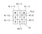
図15は、図形を表すビットマップデータの一部を示す図である。D(x,y)は注目しているビットであり、N(a,b)はD(x,y)の近傍のビットD(x+a,y+b)を表している。図15には、ビットD(x,y)と縦、横または斜め方向に隣接する8個の近傍のビットN(−1,1)、N(0,−1)、N(1,−1)、N(−1,0)、N(1,0)、N(−1,1)、N(0,1)およびN(1,1)が示されている。これらの8個の近傍のビットを8近傍と称する。N(a,b)およびD(x,y)は、それぞれ、「1」または「0」の値を有する。
【0061】
図16は、表示デバイスの表示面の一部を示す図である。P(x,y)は表示面上の1つのピクセルである。図15に示すビットD(x,y)は、ビットマップデータにより表された図形が表示デバイスに表示される際に、ピクセルP(x,y)に対応付けられる。P(x,y)は3個のサブピクセルC(3x,y)、C(3x+1,y)およびC(3x+2,y)を含み、D(x,y)が「1」の値を有する場合に3個のサブピクセルC(3x,y)、C(3x+1,y)およびC(3x+2,y)のうち、基本部分定義ルールによって基本部分に対応するサブピクセルが決定され、D(x,y)が「0」の値を有する場合には3個のサブピクセルはいずれも基本部分に対応するサブピクセルとして決定されない。なお、ここでは図15に示すビットD(x,y)を図16に示すサブピクセルのグループGrpに対応付けているが、グループに含まれるサブピクセルの数とピクセルに含まれるサブピクセルの数とが必ずしも一致していなくてもよく、例えばビットマップデータのビットを図16に示す4個のサブピクセルからなるグループGrp’に対応付けてもよい。また、グループに含まれるサブピクセルはX方向に配列しているものに限られず、例えばビットマップデータのビットを図16に示すX方向およびY方向にサブピクセルが配列するグループGrp”に対応付けてもよい。
【0062】
図17(A)は、ビットマップデータにおいて注目しているビットD(x,y)の8近傍のビット例を示す。ビットN(a,b)が「1」の値を有することをN(a,b)=1と表すと、図17(A)においてN(0,−1)=N(1,1)=1であり、N(1,0)=N(0,1)=N(−1,1)=N(−1,0)=0であり、「※」で示されるN(−1,−1)およびN(1,−1)は「0」または「1」の任意の値を有する。また、図17(B)は、ビットD(x,y)の8近傍のビットが図17(A)に示される値を有する場合に、基本部分定義ルールによって基本部分と対応付けられるサブピクセルを示す図である。基本部分定義ルールにおいて、ピクセルP(x,y)に含まれる3個のサブピクセルのそれぞれが基本部分として対応付けられるか否かは、ピクセルP(x,y)に対応付けられたビットD(x,y)の近傍のビットN(a,b)の「0」および「1」の配列によって以下のように決定される。なお、以下の説明ではビットD(x,y)は「1」の値を有するものとする。図16に示すように、ビットD(x,y)に対応付けられた表示面上のピクセルP(x,y)は、3個のサブピクセルC(3x,y)、C(3x+1,y)およびC(3x+2,y)を含み、これらのサブピクセルのうち、図17(B)に「1」で示されるサブピクセルが基本部分に対応付けられ、「0」で示されるサブピクセルは基本部分に対応付けられない。すなわち、サブピクセルC(3x+2,y)は基本部分に対応付けられ、C(3x,y)およびC(3x+1,y)は基本部分に対応付けられない。例えば、図17(A)に示すビットマップデータにおいて、ストロークはビットN(0,−1)、D(x,y)、N(1,1)に対応する領域を通る曲線(図17(A)の破線50)であると推測される。このような曲線は、ビットD(x,y)に対応する領域内部の右側を通過すると考えられるので、図17(B)においてビットD(x,y)に対応するピクセルP(x,y)に含まれる右側のサブピクセルC(3x+2,y)が基本部分に対応付けられる。
【0063】
文字の骨格を表す基本部分に対応するサブピクセル12が決定されると、そのサブピクセル12とそれに隣接するサブピクセル13とに対して色要素レベルが設定される。例えば、図2(a)に示すように、ピクセル10を構成する3つのサブピクセル11のうち、斜線で示す中央に配置されたサブピクセル12が基本部分に対応すると決定された場合、図2(b)に示すように、その基本部分に対応するサブピクセル12の色要素レベルは例えば最大のレベルとして「7」に設定される。また、基本部分に対応するサブピクセル12に隣接し、基本部分に対応しないと判断されたサブピクセル13の色要素レベルは、基本部分に対応するサブピクセル12から遠くなるにつれて順番に、例えば「5」、「2」、「1」というように段階的に小さくなるように設定される。また、基本部分に対応するサブピクセル12から4つ以上離れたサブピクセル14の色要素レベルは、背景に相当するものとして「0」に設定される。
【0064】
なお、基本部分に対応するサブピクセル12に隣接し、基本部分ではないと決定されたサブピクセル13において、そのサブピクセル13が複数の基本部分に対応するサブピクセル12と隣接している場合、基本部分に対応する複数のサブピクセル12からの距離によって複数の色要素レベルが設定されることもあるが、そのような場合には、値が大きい方の色要素レベルが優先される。
【0065】
各サブピクセルの色要素レベルは、色要素レベルと輝度レベルとの対応関係に基づいて、輝度レベルに変換される。図2(b)の例では、基本部分に対応するサブピクセル12の輝度レベルは「0」に設定される。また、そのサブピクセル12に隣接する色要素レベルが「5」のサブピクセルの輝度レベルは「73」に設定され、色要素レベルが「2」のサブピクセルの輝度レベルは「182」に設定され、色要素レベルが「1」のサブピクセルの輝度レベルは「219」に設定される。また、背景に相当するものとして色要素レベルが「0」に設定されたサブピクセル14の輝度レベルは「255」に設定される。
【0066】
このようにして輝度レベルを決定する際に、本実施形態では、図3(c)に示すように、輝度レベルが決定されるピクセル(注目ピクセル)15に含まれるM個のサブピクセル16と、その両側に隣接するN個のサブピクセル17とを加えたM+2×N個のサブピクセルに含まれる基本部分の配列パターンを抽出し、抽出された配列パターンに基づいて、注目ピクセル15に含まれるM個のサブピクセル16の輝度レベル、すなわちピクセルの画素値を決定する。
【0067】
図3は、画素値テーブル5eの一例を示す図である。この図3および以下の図4〜図7では、図2(c)に示す注目ピクセル15に含まれるサブピクセル16の個数M=3、その両側にそれぞれ隣接するサブピクセル17の個数N=3の場合について説明する。なお、上記サブピクセルの個数Nは、通常、補正パターンの要素数(図10の例では3)と同じ数が用いられる。図3の左側には、サブピクセルの配列と同じ方向に並ぶ、3つのピクセル(注目ピクセル15とその両側のピクセル)に含まれる9つのサブピクセルの配列パターンを示している。図中、「0」はそのサブピクセルが基本部分ではないことを示し、「1」はそのサブピクセルが基本部分であることを示し、「x」はそのサブピクセルが基本部分であっても基本部分でなくてもよいことを示す。また、図3の右側には、図3の左側の各配列パターンに対応する、注目ピクセルに含まれる(R、G、B)の各サブピクセルの輝度値を示している。
【0068】
このような、文字の基本部分に対応するサブピクセルの配列と、画素値(サブピクセルの輝度レベル)が決定されるピクセルに含まれるサブピクセルの輝度値との対応関係を示す画素値テーブル5eを用いて、ピクセルの画素値が決定される。
【0069】
例えば、基本部分に対するサブピクセルの配列パターンが「x1000001x」である場合、例えば図10に示す補正パターン1が選択された場合には、色要素レベルの配列パターンが「x75、212、57x」となり、画素値が決定される注目ピクセルに含まれるサブピクセル(R、G、B)の色要素レベル(2、1、2)は図11に示す色要素レベルと輝度レベルとの対応関係に従って輝度レベル(182、219、182)に変換される。このため、図3の画素値テーブル5eでは、基本部分に対するサブピクセルの配列パターン「x1000001x」とピクセルの画素値(182、219、182)とが対応付けられている。他の配列パターンについても同様に、ピクセルの画素値と対応付けられている。これらの配列パターンは、注目ピクセルに含まれるM個のサブピクセルと、その両側のピクセル(近傍ピクセル)に含まれるN個のサブピクセルとからなる(M+2N)個のサブピクセルにおける、基本部分に対応するサブピクセルの位置を数値配列により示すものである。
【0070】
図4は、画素値テーブル5eの他の例を示す図である。図4の左側には、サブピクセルの配列と同じ方向に並ぶ、3つのピクセルに含まれる9つのサブピクセルの配列パターンを示している。また、図4の右側には、図4の左側の各配列パターンに対応する、注目ピクセルに含まれる(R、G、B)の各サブピクセルの輝度値を示している。
【0071】
このような、文字の基本部分に対するサブピクセルの配列パターンと、画素値が決定されるピクセルに含まれるサブピクセルの輝度値との対応関係を示す画素値テーブル5eを用いて、ピクセルの画素値が決定される。
【0072】
例えば、基本部分に対するサブピクセルの配列パターンが「000001000」である場合、図10に示す補正パターン1が選択された場合には、色要素レベルの配列が「001、257、521」となり、画素値が決定される注目ピクセルに含まれるサブピクセル(R、G、B)の色要素レベル(2、5、7)は図11に示す色要素レベルと輝度レベルとの対応関係に従って輝度レベル(182、73、0)に変換される。このため、図4の画素値テーブル5eでは、基本部分に対するサブピクセルの配列パターン「000001000」とピクセルの画素値(182、73、0)とが対応付けられている。他の配列パターンについても同様に、ピクセルの画素値と対応付けられている。
【0073】
以上のように、基本部分に対応するサブピクセルの配列パターンと、サブピクセルの輝度値との対応関係が予め画素値テーブル5eに設定されているので、基本部分に対応するサブピクセル同士が接近している場合には、その配列パターンに対応するサブピクセルの輝度値を調整することにより、文字のストローク間に存在するピクセルの画素値をコントロールすることができる。これにより、文字のストローク間で黒味が溜まり、文字間の空間が潰れる等ということを防いで表示品位を向上させることができる。
【0074】
図5は、画素値テーブル5eの他の例を示す図である。ここでは、基本部分を移動させて文字間の空間が潰れることを防いでいる。図5の左側には、サブピクセルの配列と同じ方向に並ぶ、3つのピクセルに含まれる9つのサブピクセルの配列パターンを示している。また、図5の中央には、基本部分に対応するサブピクセルを、各ピクセルに含まれる3つのサブピクセルのうち、中央に位置するサブピクセルに置換した配列パターンを示している。図5の右側には、図5の中央の各配列パターンに対応する、注目ピクセルに含まれる(R、G、B)の各サブピクセルの輝度値を示している。
【0075】
このような、文字の基本部分に対するサブピクセルの配列パターンと、画素値が決定されるピクセルに含まれるサブピクセルの輝度値との対応関係を示す画素値テーブル5eを用いて、ピクセルの画素値が決定される。
【0076】
例えば、基本部分に対応するサブピクセルの配列が「000 001 000」である場合、基本部分を置換することによりサブピクセルの配列は「000 010 000」になる。それに伴って、図10に示す補正パターン1が選択された場合には、色要素レベルの配列が「012、575、210」となり、画素値が決定される注目ピクセルに含まれるサブピクセル(R、G、B)の色要素レベル(5、7、5)は図11に示す色要素レベルと輝度レベルとの対応関係に従って輝度レベル(73、0、73)に変換される。このため、図5の画素値テーブル5eでは、基本部分に対応するサブピクセルの配列パターン「000 001 000」とピクセルの画素値(73、0、73)とが対応付けられている。他の配列パターンについても同様に、ピクセルの画素値と対応付けられている。
【0077】
図6は、画素値テーブル5eの他の例を示す図である。ここでは、基本部分を左側に複製(多重化)して文字の線幅を太くしている。図6の左側には、サブピクセルの配列と同じ方向に並ぶ、3つのピクセルに含まれる9つのサブピクセルと、その右側に隣接するサブピクセルとの配列パターンを示している。また、図6の中央には、基本部分に対応するサブピクセルに加えて、その左側に位置するサブピクセルを基本部分として複製した配列パターンを示している。図6の右側には、図6の中央の各配列パターンに対応する、注目ピクセルに含まれる(R、G、B)の各サブピクセルの輝度値を示している。
【0078】
このような、文字の基本部分に対するサブピクセルの配列パターンと、画素値が決定されるピクセルに含まれるサブピクセルの輝度値との対応関係を示す画素値テーブル5eを用いて、ピクセルの画素値が決定される。
【0079】
例えば、基本部分に対するサブピクセルの配列パターンが「x1000001xx」である場合、基本部分を左側に複製することによりサブピクセルの配列は「x1000011xx」になる。それに伴って、図10に示す補正パターン1が選択された場合には、色要素レベルの配列が「x75、225、77x、x」となり、画素値が決定される注目ピクセルに含まれるサブピクセル(R、G、B)の色要素レベル(2、2、5)は図11に示す色要素レベルと輝度レベルとの対応関係に従って輝度レベル(182、182、73)に変換される。このため、図6の画素値テーブル5eでは、基本部分に対するサブピクセルの配列パターン「x1000001xx」とピクセルの画素値(182、182、73)とが対応付けられている。他の配列パターンについても同様に、ピクセルの画素値と対応付けられている。
【0080】
図7は、画素値テーブル5eの他の例を示す図である。ここでは、背景色がオレンジ色(R、G、B)=(255、127、0)である場合について、基本部分に対するサブピクセルの配列パターンとピクセルの画素値(R、G、B)との対応関係を示している。図7の左側には、サブピクセルの配列と同じ方向に並ぶ、3つのピクセルに含まれる9つのサブピクセルの配列パターンを示している。また、図7の右側には、図7の左側の各配列パターンに対応する、注目ピクセルに含まれる(R、G、B)の各サブピクセルの輝度値を示している。
【0081】
このような、文字の基本部分に対するサブピクセルの配列パターンと、画素値が決定されるピクセルに含まれるサブピクセルの輝度値との対応関係を示す画素値テーブル5eを用いて、ピクセルの画素値が決定される。
【0082】
例えば、基本部分に対するサブピクセルの配列パターンが「000000000」である場合、文字の基本部分に対応するサブピクセルが含まれておらず、画素値が決定されるピクセルは背景に相当するため、(R、G、B)の輝度値は(255、127、0)となる。
【0083】
また、基本部分に隣接しているサブピクセルにおいて、段階的に変化する色要素レベルは、背景色の輝度の配分に合わせて調整されている。例えば、基本部分に対するサブピクセルの配列パターンが「000001000」である場合、背景色が白の場合には、図4に示すように色要素レベルの配列は「001、257、521」となり、画素値が決定される注目ピクセルに含まれるサブピクセル(R、G、B)の色要素レベル(2、5、7)は輝度レベル(182、73、0)に変換される。これに対して、背景色がオレンジの場合には、(R、G、B)の輝度レベルの比率が(1、1/2、0)であるため、画素値が決定される注目ピクセルに含まれるサブピクセル(R、G、B)の色要素レベル(2、5、7)は、Gのレベルが73×1/2≒36となり、輝度レベル(182、36、0)に調整される。このため、図7の画素値テーブル5eでは、基本部分に対するサブピクセルの配列パターン「000001000」と調整されたピクセルの画素値(182、36、0)とが対応付けられている。他の配列パターンについても同様に、ピクセルの画素値と対応付けられている。
【0084】
任意の文字色および背景色に対する、サブピクセルの配列と設定すべきピクセルの画素値との対応関係は、図3および図4に示すような白の背景色に黒の文字色という基本的な配色における対応関係を示す画素値テーブル5eを元に、文字色と背景色とに応じて調整することができ、それぞれの配色において図7に示すような画素値テーブル5eによってピクセルの画素値を決定することができる。
【0085】
文字色と背景色との組み合わせ毎に、上記図7に示すような画素値テーブルを設けてもよく、また、上記図3および図4に示すような画素値テーブルの値を調整することによって、サブピクセルの配列と画素値との対応関係を決定することもできる。さらに、文字色と背景色との組み合わせが多数ある場合には、似通った色をグループ化して、代表となる色に対して対応関係を表す画素値テーブルを設け、文字色および背景色と代表色との差の大小に応じて対応関係を表す画素値テーブルを調整するようにしてもよい。色差の大小を判定する指標としては、例えば(R、G、B)の各色要素の差の2乗和、差の絶対値和等を用いることができる。また、視覚特性に応じた色空間(例えばYUV空間、Lab空間等)での差を色差の大小を判定する指標としてもよい。上記対応関係を表す画素値テーブルに割り当てられた代表色と、文字の表示時に指定された色との差が所定の閾値以下であれば、指定された色をその代表色を含むグループの色と判定して、その画素値テーブルを用いてピクセルの画素値を決定することができる。
【0086】
以上に説明したサブピクセルの配列とピクセルの画素値との対応関係を表す画素値テーブル5eのエントリ数は、サブピクセルの配列の組み合わせとして、(M+2×N)個のサブピクセルに対する基本部分の有無(「1」、「0」)=2(M+2 × N)通りとなる。例えば、M=N=3の場合には512通りとなる。しかしながら、図10に示すように、基本部分に対応するサブピクセルに隣接するサブピクセルの色要素レベルが段階的に変化するように補正パターンが設定されるため、サブピクセルの輝度値の配列順は限られたものになる。また、補正パターンが重なり合う個所では、色要素レベルが大きい方の値に設定されるため、画素値として取り得る値の組み合わせは、M=3の場合には5×N+8通りとなる。従って、M=N=3の場合には23通りとなり、512通りの配列パターンに23通りのインデックスを割り当てることにより、実際に設定される画素値、例えば(R、G、B)各8bit=0〜255で計24bitのデータをテーブルとして持つ場合に比べて必要とされる容量を削減することができる。但し、より精密に画素値を設定するためには、上記組み合わせの数として上記式で求められる23通りに限定されない。
【0087】
なお、以上の説明では、サブピクセルの配列とピクセルの画素値との対応関係について、注目するサブピクセルの配列を、例えばR、G、Bと並ぶサブピクセルの配列方向に沿った配列としているが、それ以外の配列、例えばR、G、Bと並ぶサブピクセルの配列方向と垂直な方向に沿った配列についても、同様の対応関係を用いることができる。
【0088】
図8は、文字形状データ5bがスケルトンデータである場合について、表示プログラム41bによる処理の流れを示すフローチャートである。
【0089】
ステップS1では、入力デバイス7から文字コード、文字サイズが入力される。例えば、漢字の「木」を表示デバイス10に表示する場合には、文字コードとして4458番(JIS区点コード、44区58点)が入力される。文字サイズは、例えば表示される文字の横方向のドット数と縦方向のドット数とによって、例えば20ドット×20ドット等のように表現される。
【0090】
ステップS2では、入力された文字コードに対応するスケルトンデータが、補助記憶装置40の文字形状データ5bから読み出され、制御装置20の主メモリ4に格納される。このスケルトンデータには、文字の種類を区別するための文字コード、1つの文字を構成するストロークの数、1つのストロークを構成する点の数、ストロークの線タイプ、1つのストロークを構成する点の座標等が含まれている。
【0091】
ステップS3では、入力デバイス7から入力された文字サイズに応じて、スケルトンデータに含まれる各ストロークを構成する点の座標データがスケーリングされる。このスケーリングによって、スケルトンデータに含まれる座標データのために予め定められた座標系から、表示デバイス10のために定められた実ピクセル座標系に変換される。このときのスケーリングは、サブピクセルの配列を考慮して行われる。例えば、1つのピクセル10が図13(a)に示すようにX方向に配列された3個のサブピクセル11を有し、文字サイズが20ドット×20ドットである場合には、スケルトンデータの座標データは60(=20×3)ピクセル×20ピクセルのデータとなるようにスケーリングされる。
【0092】
ステップS4では、1つのストロークを構成する点の座標データが取り出される。
【0093】
ステップS5では、スケルトンデータに含まれるストロークの線タイプからストロークの種類が直線であるか、または曲線であるかが判定される。そして、ストロークの種類が直線である場合にはステップS6に進み、ストロークの種類が直線ではなく、曲線である場合にはステップS7に進む。
【0094】
ステップS6では、ストロークを構成する点の座標データが直線で結ばれ、その直線上に配置されるサブピクセルが、文字の骨格を表す基本部分として定義される。また、ステップS7では、ストロークを構成する点の座標データが曲線で近似され、その曲線上に配置されるサブピクセルが、文字の骨格を表す基本部分として定義される。
【0095】
ステップS10では、1文字に含まれるストロークの全てに対して処理が終了したか否かが判定され、「Yes」の場合にはステップS101に進み、「No」の場合にはステップS3に戻って処理を続ける。
【0096】
ステップS101では、画素値(サブピクセルの輝度レベル)が決定されるピクセルに含まれるサブピクセルと、それに隣接するサブピクセルとの中から、上記ステップS6またはステップS7で定義された、文字の骨格を表す基本部分に対するサブピクセルの配列パターンを抽出する。
【0097】
ステップS102では、基本部分に対応するサブピクセルの配列パターンとピクセルの画素値(サブピクセルの輝度レベル)との対応関係を表す画素値テーブル5eを参照して、ステップS101で抽出された基本部分の配列パターンに対応する画素値が、注目しているピクセルに含まれるサブピクセルの輝度レベルとして設定される。
【0098】
ステップS12では、ステップS102で設定されたサブピクセルの輝度レベルを示す輝度データが、表示デバイス3に転送される。
【0099】
このようにして、基本部分に対するサブピクセルの配列パターンに基づいてサブピクセル単位で輝度レベルを調節して、表示デバイス3に文字を表示することができる。ここでは、文字の骨格を表す基本部分に対応するサブピクセルは、スケルトンデータから導出しているが、アウトラインデータ、ビットマップデータ等から所定の処理によって導出してもよく、また、基本部分のパターンを文字形状データとして予め補助記憶装置40に格納しておいたものを読み出して用いることもできる。
【0100】
【発明の効果】
以上詳述したように、本発明によれば、カラー表示が可能な表示部において高精細に文字を表示する際に、文字の骨格を表す基本部分に対するサブピクセルの配列パターンから、表示部において表示すべき輝度レベルに直接変換することができるため、処理を高速化することができ、また処理を行うための作業メモリ領域を少なくすることができる。その結果、文字表示処理を高速化することができ、また、ハードウェアのコストを削減することができる。
【0101】
また、文字のストローク同士が近接している個所において、文字の骨格を表す基本部分に対するサブピクセルの配置パターンを調整することによって、文字が潰れることを容易に回避することができる。また、文字の骨格を表す基本部分に対応するサブピクセルに加えてその近傍のサブピクセルを基本部分のサブピクセルとして配列パターンを調整することによって、文字の線幅を容易に太くすることができる。
【0102】
また、表示されるべき文字および背景に任意の色を設定する場合に、文字色および背景色に応じて、サブピクセルの配列とサブピクセルの輝度レベルとの対応関係を調整することによって、配色によらず、文字の形状を保ちつつ、視認性の高い文字表示を行うことができる。
【0103】
さらに、基本部分に対するサブピクセルの配列パターンとピクセルの画素値との対応関係は、文字と背景との任意の配色に対して、似通った配色をグループ化して、代表色に関する対応関係のテーブルに集約することができるため、基本部分に対するサブピクセルの配列パターンとピクセルの画素値との対応関係のテーブル必要なデータ量を削減することができる。
【図面の簡単な説明】
【図1】本発明の一実施形態である文字表示装置の構成を示すブロック図である。
【図2】(a)〜(c)は、本発明の一実施形態である文字表示装置におけるサブピクセルの構造と補正パターンについて説明するための図である。
【図3】本発明の一実施形態である文字表示装置における画素値テーブルの一例を示す図である。
【図4】本発明の一実施形態である文字表示装置における画素値テーブルの他の例を示す図である。
【図5】本発明の一実施形態である文字表示装置における画素値テーブルの他の例を示す図である。
【図6】本発明の一実施形態である文字表示装置における画素値テーブルの他の例を示す図である。
【図7】本発明の一実施形態である文字表示装置における画素値テーブルの他の例を示す図である。
【図8】本発明の一実施形態である文字表示方法の処理手順を説明するためのフローチャートである。
【図9】文字「忙」について、基本部分に対応するサブピクセルのパターン例を示す図である。
【図10】従来の文字表示装置における補正テーブルの例を示す図である。
【図11】従来の文字表示装置における輝度テーブルの例を示す図である。
【図12】従来の文字表示装置の構成を示すブロック図である。
【図13】(a)および(b)は、従来の文字表示装置におけるサブピクセルの構造と補正パターンについて説明するための図である。
【図14】従来の文字表示方法の処理手順を説明するためのフローチャートである。
【図15】図形を表すビットマップデータの一部を示す図である。
【図16】表示デバイスの表示面の一部を示す図である。
【図17A】ビットマップデータにおいて注目しているビットと8近傍の例を示す図である。
【図17B】図17(A)に示す注目ビットと8近傍において、基本部分定義ルールによって基本部分として対応付けられるサブピクセルを示す図である。
【符号の説明】
1a、1b 文字表示装置
2 CPU
3 表示デバイス
4 主メモリ
5 データ
5b 文字形状データ
5c 補正テーブル
5d 輝度テーブル
5e 画素値テーブル
7 入力デバイス
10 ピクセル
11 サブピクセル
12 文字の骨格形状を表す基本部分に対応するサブピクセル
13 基本部分に対応するサブピクセルに隣接するサブピクセル
14 基本部分に対応するサブピクセルから4つ以上離れたサブピクセル
15 注目ピクセル
16 注目ピクセルに含まれるサブピクセル
17 注目ピクセルに隣接するサブピクセル
40 補助記憶装置
41a、41b 表示プログラム[0001]
BACKGROUND OF THE INVENTION
The present invention includes a character display device that includes a display unit capable of color display and capable of displaying characters with high definition, a character display method, a control program for controlling the character display method, and a control program recorded therein The recorded recording medium.
[0002]
[Prior art]
Some personal computers, word processors, mobile phones, and the like include a display unit capable of color display. As a technique for displaying characters with high definition in such a device, for example, Japanese Patent Application Laid-Open No. 2001-100725 discloses the following character display device.
[0003]
In this character display device, a plurality of pixels are provided on the display surface of the display device, and each pixel is arranged in a predetermined direction, for example, a plurality of pixels such as R: red, G: green, and B: blue. A plurality of subpixels to which a corresponding one of the color elements is respectively assigned are included. The strength of the color element in each sub-pixel is represented by a color element level set in a plurality of stages such as 0 to 7, for example, and one of the color element levels corresponds to the character skeleton. When assigned to a subpixel, the color element level is assigned to the surrounding subpixels so that the color element level changes step by step around the subpixel, and a pattern of a predetermined color element level is set. The Each color element level is converted into a luminance level based on a predetermined correspondence.
[0004]
Since the color element level corresponds to the degree of contribution to the character color, the sub-pixel that contributes to the character color has a higher color element level, and the sub-pixel that contributes to the background color has a higher color element level. Lower. The luminance level corresponds to the light emission level of each subpixel. The higher the luminance level, the stronger the light emission level of the subpixel, and the lower the luminance level, the weaker the light emission level. Thus, by controlling the color element level in units of sub-pixels and representing the shape of the characters, it is possible to display characters with higher definition than in the case where the luminance level is controlled in units of pixels. In addition, color noise can be suppressed by forming a color element level pattern that changes stepwise around a subpixel corresponding to a character skeleton.
[0005]
Japanese Patent Laid-Open No. 2001-184051 discloses an arbitrary character color by appropriately changing the predetermined correspondence between the color element level and the luminance level according to the character color to be displayed and the background color. In addition, a character display device capable of high-definition character display in any background color is disclosed.
[0006]
FIG. 12 is a block diagram showing a typical configuration of the character display device disclosed in Japanese Patent Laid-Open Nos. 2001-100725 and 2001-184051.
[0007]
As this character display device 1a, any information display device such as an electronic device or an information device provided with a display device capable of color display can be used. For example, any type such as a desktop type or a laptop type can be used. A personal computer, a word processor, etc. are mentioned. Furthermore, it may be an electronic device provided with a color liquid crystal display device, or may be a communication device such as a portable information terminal, a mobile phone including a PHS, a general fixed phone, or a FAX.
[0008]
The character display device 1 a has a
[0009]
The
[0010]
The
[0011]
The
[0012]
The correction table 5c is used to set the color element level of the subpixel adjacent to the subpixel corresponding to the basic part. For example, when the color element level of the subpixel corresponding to the basic part is 7, the correction table 5c is adjacent to the subpixel. The color element levels of the subpixels to be set are set to 5, 2, 1, etc. in order from the side closer to the basic portion. In the luminance table 5d, the correspondence between the color element level and the luminance level is set.
[0013]
FIG. 13A and FIG. 13B are diagrams for explaining the configuration of the display surface of the
[0014]
When a character is displayed on the display surface, a basic portion representing a character skeleton is associated with the
[0015]
When associating the basic portion representing the character skeleton with the
[0016]
The skeleton data includes character codes for distinguishing character types, the number of strokes constituting one character, the number of points constituting one stroke, the stroke line type (curve, straight line, etc.), 1 The coordinates of the points that make up one stroke are included. In this case, each stroke is a linear shape corresponding to each line type and has no thickness in order to represent the skeleton shape of the character. If the stroke line type is a straight line, each stroke can be approximated as a straight line passing through those points using the coordinate data of multiple points that make up each stroke. In this case, the coordinate data of a plurality of points constituting each stroke can be used to approximate as a curve passing through those points. Then, the sub-pixels 11 arranged on each stroke are determined as the sub-pixels 12 corresponding to the basic portion representing the character skeleton.
[0017]
When the subpixel 12 corresponding to the basic portion representing the character skeleton is determined, the color element level is set for the subpixel 12 and the
[0018]
In addition, in the
[0019]
The color element level of each sub-pixel is converted into a luminance level based on the correspondence relationship between the color element level and the luminance level set in the luminance table 5d illustrated in FIG. In the example of FIG. 13B, the luminance level of the sub-pixel 12 corresponding to the basic portion is set to “0”. In addition, the luminance level of the sub-pixel having the color element level “5” adjacent to the sub-pixel 12 is set to “73”, and the luminance level of the sub-pixel having the color element level “2” is set to “182”. The luminance level of the sub-pixel having the color element level “1” is set to “219”. Further, the luminance level of the sub-pixel 14 in which the color element level is set to “0” as being equivalent to the background is “255"Is set.
[0020]
FIG. 14 is a flowchart showing the flow of processing by the
[0021]
In step S1, a character code and a character size are input from the
[0022]
In step S <b> 2, skeleton data corresponding to the input character code is read from the
[0023]
In step S3, the coordinate data of points constituting each stroke included in the skeleton data is scaled according to the character size input from the
[0024]
In step S4, coordinate data of points constituting one stroke is extracted, and in step S5, it is determined whether the stroke type is a straight line or a curve from the stroke line type included in the skeleton data. . If the stroke type is a straight line, the process proceeds to step S6. If the stroke type is not a straight line but a curve, the process proceeds to step S7.
[0025]
In step S6, the coordinate data of the points constituting the stroke are connected by a straight line, and the sub-pixels arranged on the straight line are defined as the basic part representing the character skeleton. In step S7, the coordinate data of the points constituting the stroke is approximated by a curve, and the sub-pixels arranged on the curve are defined as basic portions representing the character skeleton.
[0026]
In step S8, the color element of the sub-pixel corresponding to the basic part representing the character skeleton defined in step S6 or step S7 is set as the maximum color element level, for example, “7”. Next, in step S9, with reference to the correction table 5c, the color element level of the sub pixel near the sub pixel corresponding to the basic portion is set.
[0027]
In step S10, it is determined whether or not the processing has been completed for all the strokes included in one character. If “Yes”, the process proceeds to step S11. If “No”, the process returns to step S3. Continue processing. In step S11, the color element level of the set sub-pixel is converted into each luminance level with reference to the luminance table 5d representing the correspondence between the color element level and the luminance level. In step S12, the luminance data indicating the luminance level of the sub-pixel set in step S11 is transferred to the
[0028]
In this way, it is possible to display characters on the
[0029]
[Problems to be solved by the invention]
However, in the above-described conventional technology, since the color element level pattern of the sub-pixels constituting the character shape is set and then converted into the luminance level to be actually displayed on the display unit, the processing becomes complicated, In addition, the working memory area required for processing increases. For this reason, there are problems such as a slow process for displaying characters and an increase in hardware costs.
[0030]
Further, in the above prior art, in order to prevent the “character collapse” that the space portion of the character becomes narrow due to the approach or crossing of two or more strokes having a predetermined width and the shape of the character becomes difficult to recognize. Changing the pattern of the color element level of pixels has been performed. However, in order to actually recognize the positional relationship between the strokes and change the color element level pattern, there is a problem that complicated processing is required.
[0031]
Furthermore, when any color is set for the character and background to be displayed, depending on the combination of the character color and the background color, the pattern of the subpixel color element level will change the set character and background color. This is not suitable for expression, and there is a problem that the visibility is remarkably deteriorated by losing the shape of the character.
[0032]
The present invention has been made to solve such problems of the prior art, and displays high-definition and high-quality characters by simple processing, speeding up character display processing, and reducing hardware costs. An object of the present invention is to provide a character display device and a character display method that can be realized, a control program for controlling the character display method, and a recording medium on which the control program is recorded.
[0033]
[Means for Solving the Problems]
The character display device of the present invention includes:A plurality of pixels each including a plurality of subpixels arranged in a predetermined direction and each assigned a corresponding at least one color element of the plurality of color elements;A display unit for displaying characters and a control unit for controlling the display unitA luminance level of the sub-pixel is determined for each pixel, and characters are displayed on the display surface of the display unit.In the character display device, the control unit, based on the character shape data representing the character shape,TheCorresponds to the basic part that represents the skeleton of the character from multiple subpixelsCorrespondenceDetermine the subpixel,That subpixelThe brightness level is determinedAttentionThe sub-pixels contained in the pixel andIn an array of a plurality of subpixels consisting of subpixels included in neighboring pixels on both sides of the target pixel,Corresponding to the basic partCorrespondenceSubpixelShows the position of as a numeric arrayThe sequence pattern is extracted and the extracted, At least one of the group of sub-pixelsSubpixelFor the array pattern indicating that the corresponding sub-pixel is the corresponding sub-pixel, by replacing the position of the corresponding sub-pixel indicated by the array pattern with the position of the non-corresponding sub-pixel not corresponding to the basic part adjacent to the array pattern. Or a predetermined change including a change in which the arrangement pattern is changed to the one in which the position of the non-corresponding subpixel adjacent to the position of the corresponding subpixel indicated by this is also indicated as the position of the corresponding subpixel. Included in the pixel of interest based on the patternDetermine subpixel brightness levelWhat to doThis achieves the above object.
[0034]
The controller isAs a change to the array pattern,Corresponding to the basic partCorrespondenceSubpixel location and adjacent to it, Not compatible with the basic partSub-pixel positionReplaceReplaceAddedArraypatternOn the basis of the,Included in the pixel of interestDetermine subpixel brightness levelTo do.
[0035]
The controller isAs a change to the array pattern,Corresponding to the basic partCorrespondenceSubpixelIn the positionAdjacent, Not compatible with the basic partSubpixelAdded a duplicate to indicate the position of as a corresponding subpixel positionArraypatternOn the basis of the,Included in the pixel of interestDetermine subpixel brightness levelTo do.
[0036]
The control unit uses a combination of the character color to be displayed and the background color.Depending onThe aboveEach subpixel in the pixel of interest and itsChanged correspondence with brightness levelTo do.
[0037]
The control unit determines whether the character color and background color registered in advance are different from the color of the character to be displayed and the color of the background.Each sub-pixel in the pixel of interest determined from the array pattern and,ThatChanged correspondence with brightness levelTo do.
[0038]
The character display method of the present invention includes a plurality of pixels each including a plurality of sub-pixels arranged in a predetermined direction and each assigned a corresponding at least one color element among the plurality of color elements. In a character display device having a display unit on which is displayed and a control unit for controlling the display unit,For each pixel, determine the luminance level of the sub-pixel.Display surface of the display unitSentenceA method for displaying a character, based on character shape data representing the shape of the character,TheCorresponds to the basic part that represents the skeleton of the character from multiple subpixelsCorrespondenceDetermining a subpixel; andThat subpixelThe brightness level is determinedAttentionThe sub-pixels contained in the pixel andIncluded in neighboring pixels on both sides of the pixel of interestSubpixelIn an array of a plurality of subpixels consisting ofCorresponding to the basic partCorrespondenceSub-pixelShow position as numeric arrayThe step of extracting the sequence pattern and the extracted, At least one of the group of sub-pixelsSubpixelIndicates that is the corresponding sub-pixelArray patternOn the other hand, a replacement in which the position of the corresponding subpixel indicated by the arrangement pattern is replaced with the position of a non-corresponding subpixel that does not correspond to the basic portion adjacent to the arrangement pattern, or the correspondence indicated by the arrangement pattern. A predetermined change including a copy that changes the position of the non-corresponding subpixel adjacent to the position of the subpixel to the one that also indicates the position of the corresponding subpixel is added, and the pixel of interest is included based on the changed arrangement patternDetermining the luminance level of the sub-pixel;
Thereby achieving the above object.
[0039]
The control program of the present invention has a plurality of pixels each including a plurality of subpixels arranged in a predetermined direction and each assigned a corresponding at least one color element among the plurality of color elements, and the character is In a character display device having a display unit to be displayed and a control unit for controlling the display unit,For each pixel, determine the luminance level of the sub-pixel.Characters are displayed on the display surface of the display unitFor executing the character display processA control program,The character display processBased on the character shape data representing the character shape,TheCorresponds to the basic part that represents the skeleton of the character from multiple subpixelsCorrespondenceDetermine subpixelSteps to do,That subpixelThe brightness level is determinedAttentionThe sub-pixels contained in the pixel andIn an array of a plurality of subpixels consisting of subpixels included in neighboring pixels on both sides of the target pixel,Corresponding to the basic partCorrespondenceSubpixelShows the position of as a numeric arrayExtract sequence patternSteps to doExtracted, Indicating that at least one subpixel of the group of subpixels is the corresponding subpixelArray patternOn the other hand, a replacement in which the position of the corresponding subpixel indicated by the arrangement pattern is replaced with the position of a non-corresponding subpixel that does not correspond to the basic portion adjacent to the arrangement pattern, or the correspondence indicated by the arrangement pattern. A predetermined change including a copy that changes the position of the non-corresponding subpixel adjacent to the position of the subpixel to the one that also indicates the position of the corresponding subpixel is added, and the pixel of interest is included based on the changed arrangement patternDetermine the luminance level of the subpixelIncluding stepsThis achieves the above object.
[0040]
The recording medium of the present invention is arranged in a predetermined direction.DoubleA corresponding at least one of the number of color elements is respectively assignedTheA character display device having a plurality of pixels each including a plurality of sub-pixels and displaying a character, and a control unit for controlling the display unitIn the character display device, a control program for determining the luminance level of each sub-pixel for each pixel and executing a character display process for displaying characters on the display surface of the display unit is recorded.ThereforeOf the control programreadingButA possible recording medium,The character display processBased on the character shape data representing the character shape,TheCorresponds to the basic part that represents the skeleton of the character from multiple subpixelsCorrespondenceDetermine subpixelSteps to do,That subpixelThe brightness level is determinedAttentionThe sub-pixels contained in the pixel andIn an array of a plurality of subpixels consisting of subpixels included in neighboring pixels on both sides of the target pixel,Corresponding to the basic partCorrespondenceSubpixelShows the position of as a numeric arrayExtract sequence patternSteps to doExtracted, At least one of the group of sub-pixelsSubpixelIndicates that is the corresponding sub-pixelArray patternIs replaced with the position of the corresponding subpixel indicated by the arrangement pattern and the position of the non-corresponding subpixel that does not correspond to the basic part adjacent to the arrangement pattern.(Paragraphs 0074 to 0076, FIG. 5)Or by making a predetermined change including duplication that changes the position of the non-corresponding subpixel adjacent to the position of the corresponding subpixel indicated by this position to the position indicating the position of the corresponding subpixel, and based on the changed array pattern Included in the target pixelDetermine the luminance level of the subpixelStep andincludingIs a thingThis achieves the above object.
[0041]
The operation of the present invention will be described below.
[0042]
In the present invention, the display surface of the display unit includes a plurality of subpixels arranged in a predetermined direction and each assigned with at least one corresponding color element among the plurality of color elements. Pixels are provided. When displaying characters on the display surface of the display unit, for example, character shapes such as skeleton data representing character skeleton shapes, outline data representing character outline shapes, bitmap data representing character shapes, etc. Based on the character shape data representing, a subpixel corresponding to the basic portion representing the skeleton of the character is determined from among the plurality of subpixels. Then, an array of subpixels corresponding to the basic part is extracted from the subpixels included in the pixel whose luminance level is determined and its neighboring subpixels. Based on the extracted subpixel array, The luminance level of the sub-pixel is determined, and characters are displayed on the display unit.
[0043]
As a result, when displaying characters in high definition and high quality, after determining the color element level of the subpixel corresponding to the basic part and the color element level of the subpixel adjacent to the subpixel corresponding to the basic part, respectively. Compared with the prior art that converts to a luminance level, the luminance level can be determined by simply extracting an array of sub-pixels corresponding to the basic portion. Processing can be performed at a practical speed. In addition, since the size of the control program in which the processing procedure is described can be reduced, the size of the auxiliary storage device can be reduced. Furthermore, by simplifying the processing, the working memory area required during the processing can be kept small. As a result, high-definition and high-quality character display can be realized while reducing the cost of the character display device.
[0044]
In the present invention, when determining the luminance level of a plurality of subpixels based on the arrangement of the subpixels corresponding to the basic part, the position of the subpixel corresponding to the basic part and the subpixels adjacent thereto are determined. And the luminance level of the sub-pixel can be determined based on the substituted array. As a result, when the subpixels that are the skeletons of the characters are close to each other, the arrangement of the subpixels can be changed so as to increase the distance between the skeletons, so when the strokes of the characters are close to each other, It is possible to prevent the space between strokes from being lost and the characters from being crushed. In addition, depending on the color scheme between the character and the background, the arrangement of the subpixels that are the skeleton of the character may not be suitable for the representation of the character shape. By changing, the distortion of the character shape can be corrected.
[0045]
In the present invention, when determining the luminance level of a plurality of subpixels based on the arrangement of subpixels corresponding to the basic part, in addition to the subpixels corresponding to the basic part, the subpixels adjacent thereto As a basic part, and based on the replicated array, the luminance level of the sub-pixel can be determined. As a result, the sub-pixels that become the skeleton of the character can be multiplexed, so that the processing for increasing the line width of the character can be simplified and performed efficiently.
[0046]
Further, in the present invention, when determining the luminance level of the plurality of subpixels based on the arrangement of the subpixels corresponding to the basic portion, the combination of the character color to be displayed and the background color, The correspondence between the subpixel array and the luminance level of the subpixel can be changed. As a result, since the optimum luminance level of the subpixel can be determined according to the color of the character and the background color, the character can be displayed with the optimum line width for each color scheme, regardless of the color scheme, Character display with high visibility can be performed.
[0047]
Further, in the present invention, when the luminance level of a plurality of subpixels is determined based on the arrangement of subpixels corresponding to the basic portion, the character color and background color registered in advance are displayed. The correspondence between the arrangement of the subpixels and the luminance level of the subpixels can be changed depending on the difference between the color of the power character and the background color. As a result, it is possible to share the above correspondence for groups of characters with similar subpixel luminance levels and similar color schemes, so that a wider range of color schemes can be achieved while keeping the storage capacity of the character display device small. Characters can be displayed with the optimum line width.
[0048]
DETAILED DESCRIPTION OF THE INVENTION
Embodiments of the present invention will be described below with reference to the drawings.
[0049]
FIG. 1 is a block diagram showing a configuration of a character display device according to an embodiment of the present invention. As this
[0050]
This
[0051]
The
[0052]
The
[0053]
The
[0054]
The pixel value table 5e is included in M + 2 × N sub-pixels obtained by adding M sub-pixels included in a pixel (target pixel) whose luminance level is determined and N sub-pixels adjacent to both sides thereof. The correspondence relationship between the arrangement pattern of the basic portion and the luminance levels (pixel values of the pixels) of the M sub-pixels included in the target pixel is set.These arrangement patterns correspond to the basic portion of (M + 2N) sub-pixels including M sub-pixels included in the target pixel and N sub-pixels included in pixels on the both sides (neighboring pixels). The position of the sub-pixel to be displayed is indicated by a numerical array.
[0055]
2A to 2C are diagrams for explaining the configuration of the display surface of the
[0056]
When a character is displayed on the display surface, a basic portion representing a character skeleton is associated with the
[0057]
When associating the basic portion representing the character skeleton with the sub-pixel 11, different processing is performed depending on the type of the
[0058]
The skeleton data includes character codes for distinguishing character types, the number of strokes constituting one character, the number of points constituting one stroke, the stroke line type (curve, straight line, etc.), 1 The coordinates of the points that make up one stroke are included. In this case, each stroke is a linear shape corresponding to each line type and has no thickness in order to represent the skeleton shape of the character. If the stroke line type is a straight line, each stroke can be approximated as a straight line passing through those points using the coordinate data of multiple points that make up each stroke. In this case, the coordinate data of a plurality of points constituting each stroke can be used to approximate as a curve passing through those points. Then, the sub-pixels 11 arranged on each stroke are determined as the sub-pixels 12 corresponding to the basic portion representing the character skeleton.
[0059]
The bitmap data is binary, and each bit constituting the bitmap data has a value of “1” or “0”. A bit having a value of “1” represents a black portion of the graphic, and a bit having a value of “0” represents a white portion of the graphic. The basic part is a part corresponding to the core of the figure. When the figure is a character, the basic part is, for example, the central part of a stroke (one stroke) included in the character. Is lost, so the basic part is associated by guessing. The basic part cannot be estimated only by the information of the bit D (x, y) of interest, but is estimated based on the information of the bits in the vicinity of the bit D of interest. First, for each bit constituting the bitmap data, it is determined whether or not the bit is “1”, and the arrangement pattern of “1” / “0” of bits in the vicinity of the bit of interest is examined. Then, the target bit is associated with one of the pixels, and the sub-pixel 12 corresponding to the basic portion is determined among the sub-pixels included in the pixel corresponding to the target bit according to the arrangement pattern of the neighboring bits. Is done.
[0060]
FIG. 15 is a diagram illustrating a part of bitmap data representing a graphic. D (x, y) is a bit of interest, and N (a, b) represents a bit D (x + a, y + b) in the vicinity of D (x, y). FIG. 15 shows eight neighboring bits N (−1,1), N (0, −1), N (1, −1) adjacent to the bit D (x, y) in the vertical, horizontal, or diagonal directions. ), N (-1, 0), N (1, 0), N (-1, 1), N (0, 1) and N (1, 1). These eight neighboring bits are referred to as eight neighbors. N (a, b) and D (x, y) each have a value of “1” or “0”.
[0061]
FIG. 16 is a diagram illustrating a part of the display surface of the display device. P (x, y) is one pixel on the display surface. The bit D (x, y) shown in FIG. 15 is associated with the pixel P (x, y) when the graphic represented by the bitmap data is displayed on the display device. P (x, y) includes three subpixels C (3x, y), C (3x + 1, y) and C (3x + 2, y), and D (x, y) has a value of “1” Among the three subpixels C (3x, y), C (3x + 1, y) and C (3x + 2, y), the subpixel corresponding to the basic part is determined by the basic part definition rule, and D (x, y ) Has a value of “0”, none of the three subpixels is determined as a subpixel corresponding to the basic portion. Here, the bit D (x, y) shown in FIG. 15 is associated with the sub-pixel group Grp shown in FIG. 16, but the number of sub-pixels included in the group, the number of sub-pixels included in the pixel, and May not necessarily match. For example, the bits of the bitmap data may be associated with a group Grp ′ composed of four subpixels as shown in FIG. The subpixels included in the group are not limited to those arranged in the X direction. For example, the bits of the bitmap data are associated with the group Grp ″ in which the subpixels are arranged in the X direction and the Y direction shown in FIG. Also good.
[0062]
FIG. 17A shows an example of 8 neighboring bits of the bit D (x, y) of interest in the bitmap data. N (a, b) that bit N (a, b) has a value of “1”= 1In FIG. 17A, N (0, -1) = N (1,1) = 1, and N (1,0) = N (0,1) = N (-1,1). = N (-1, 0) = 0, and N (-1, -1) and N (1, -1) indicated by "*" have arbitrary values of "0" or "1". FIG. 17B shows subpixels that are associated with the basic part by the basic part definition rule when 8 neighboring bits of the bit D (x, y) have the values shown in FIG. FIG. In the basic part definition rule, whether or not each of the three sub-pixels included in the pixel P (x, y) is associated as a basic part is determined by the bit D () associated with the pixel P (x, y). It is determined as follows by the arrangement of “0” and “1” of the bits N (a, b) in the vicinity of x, y). In the following description, it is assumed that bit D (x, y) has a value of “1”.FIG.As shown in FIG. 4, the pixel P (x, y) on the display surface associated with the bit D (x, y) includes three subpixels C (3x, y), C (3x + 1, y), and C (3x + 2, y), among these subpixels, the subpixel indicated by “1” in FIG. 17B is associated with the basic portion, and the subpixel indicated by “0” corresponds to the basic portion. Can't be attached. That is, the subpixel C (3x + 2, y) is associated with the basic part, and C (3x, y) and C (3x + 1, y) are not associated with the basic part. For example, in the bitmap data shown in FIG. 17A, the stroke is a curve passing through an area corresponding to bits N (0, −1), D (x, y), and N (1, 1) (FIG.It is estimated that this is the broken line 50) of (A). Since such a curve is considered to pass through the right side inside the region corresponding to the bit D (x, y), the pixel P (x, y) corresponding to the bit D (x, y) in FIG. The right sub-pixel C (3x + 2, y) included in is associated with the basic portion.
[0063]
When the subpixel 12 corresponding to the basic portion representing the character skeleton is determined, the color element level is set for the subpixel 12 and the
[0064]
In addition, in the
[0065]
The color element level of each subpixel is converted into a luminance level based on the correspondence between the color element level and the luminance level. In the example of FIG. 2B, the luminance level of the sub-pixel 12 corresponding to the basic portion is set to “0”. In addition, the luminance level of the sub-pixel having the color element level “5” adjacent to the sub-pixel 12 is set to “73”, and the luminance level of the sub-pixel having the color element level “2” is set to “182”. The luminance level of the sub-pixel having the color element level “1” is set to “219”. Further, the luminance level of the sub-pixel 14 in which the color element level is set to “0” as being equivalent to the background is “255"Is set.
[0066]
When determining the luminance level in this way, in the present embodiment, as shown in FIG. 3C, M sub-pixels 16 included in the pixel (target pixel) 15 for which the luminance level is determined; Arrangement of basic parts included in M + 2 × N sub-pixels including N sub-pixels 17 adjacent on both sides thereofpatternAnd the luminance levels of the M sub-pixels 16 included in the target pixel 15, that is, the pixel values of the pixels are determined based on the extracted array pattern.
[0067]
FIG. 3 is a diagram illustrating an example of the pixel value table 5e. In FIG. 3 and FIGS. 4 to 7 below, the number M of
[0068]
A pixel value table 5e indicating a correspondence relationship between such an array of subpixels corresponding to the basic portion of the character and the luminance values of the subpixels included in the pixel whose pixel value (luminance level of the subpixel) is determined. Used to determine the pixel value of the pixel.
[0069]
For example, an array of subpixels for the base partpatternIs “x1000001x”, for example, when the
[0070]
FIG. 4 is a diagram illustrating another example of the pixel value table 5e. The left side of FIG. 4 shows an arrangement pattern of nine subpixels included in three pixels arranged in the same direction as the subpixel arrangement. Also, the right side of FIG. 4 shows the luminance values of the (R, G, B) subpixels included in the target pixel corresponding to the respective arrangement patterns on the left side of FIG.
[0071]
Such as the basic part of the characterAgainstArray of subpixelspatternThe pixel value of the pixel is determined using the pixel value table 5e indicating the correspondence between the luminance value of the sub-pixel included in the pixel whose pixel value is determined.
[0072]
For example, in the basic partAgainstArray of subpixelspatternIs “000001000”, and when the
[0073]
As described above, since the correspondence relationship between the subpixel arrangement pattern corresponding to the basic portion and the luminance value of the subpixel is set in the pixel value table 5e in advance, the subpixels corresponding to the basic portion approach each other. In this case, the pixel value of the pixel existing between the strokes of the character can be controlled by adjusting the luminance value of the sub-pixel corresponding to the arrangement pattern. As a result, it is possible to improve display quality by preventing blackness from being accumulated between strokes of the characters and collapsing the spaces between the characters.
[0074]
FIG. 5 is a diagram illustrating another example of the pixel value table 5e. Here, the basic part is moved to prevent the space between characters from being crushed. The left side of FIG. 5 shows an array pattern of nine subpixels included in three pixels arranged in the same direction as the subpixel array. 5 shows an arrangement pattern in which subpixels corresponding to the basic portion are replaced with subpixels located at the center among the three subpixels included in each pixel. The right side of FIG. 5 shows the luminance values of the (R, G, B) sub-pixels included in the pixel of interest corresponding to the respective array pattern in the center of FIG.
[0075]
Such as the basic part of the characterAgainstArray of subpixelspatternThe pixel value of the pixel is determined using the pixel value table 5e indicating the correspondence between the luminance value of the sub-pixel included in the pixel whose pixel value is determined.
[0076]
For example, when the arrangement of the subpixels corresponding to the basic part is “000 001 000”, the arrangement of the subpixels becomes “000 010 000” by replacing the basic part. Accordingly, when the
[0077]
FIG. 6 is a diagram illustrating another example of the pixel value table 5e. Here, the basic portion is duplicated (multiplexed) on the left side to increase the line width of the character. The left side of FIG. 6 shows an arrangement pattern of nine subpixels included in three pixels arranged in the same direction as the subpixel arrangement and adjacent subpixels on the right side thereof. In addition, in the center of FIG. 6, an array pattern is shown in which a subpixel located on the left side of the subpixel corresponding to the basic portion is copied as a basic portion. The right side of FIG. 6 shows the luminance values of (R, G, B) sub-pixels included in the pixel of interest, corresponding to each array pattern in the center of FIG.
[0078]
Such as the basic part of the characterAgainstArray of subpixelspatternThe pixel value of the pixel is determined using the pixel value table 5e indicating the correspondence between the luminance value of the sub-pixel included in the pixel whose pixel value is determined.
[0079]
For example, in the basic partAgainstArray of subpixelspatternIs “x1000001xx”, the sub-pixel arrangement is “x1000011xx” by duplicating the basic part on the left side. Accordingly, when the
[0080]
FIG. 7 is a diagram illustrating another example of the pixel value table 5e. Here, in the case where the background color is orange (R, G, B) = (255, 127, 0), the basic partAgainstArray of subpixelspatternAnd the pixel values (R, G, B) of the pixels. The left side of FIG. 7 shows an array pattern of nine subpixels included in three pixels arranged in the same direction as the subpixel array. Further, on the right side of FIG. 7, the luminance values of the (R, G, B) subpixels included in the target pixel corresponding to the respective arrangement patterns on the left side of FIG. 7 are illustrated.
[0081]
Such as the basic part of the characterAgainstArray of subpixelspatternThe pixel value of the pixel is determined using the pixel value table 5e indicating the correspondence between the luminance value of the sub-pixel included in the pixel whose pixel value is determined.
[0082]
For example, in the basic partAgainstArray of subpixelspatternIs “000000000000”, the sub-pixel corresponding to the basic part of the character is not included, and the pixel whose pixel value is determined corresponds to the background. Therefore, the luminance value of (R, G, B) is ( 255, 127, 0).
[0083]
In addition, in the sub-pixels adjacent to the basic portion, the color element level that changes stepwise is adjusted in accordance with the distribution of the luminance of the background color. For example, in the basic partAgainstArray of subpixelspatternIs “000001000”, and when the background color is white, the color element level array is “001, 257, 521” as shown in FIG. 4, and the sub-pixel included in the target pixel whose pixel value is determined. The color element levels (2, 5, 7) of the pixels (R, G, B) are converted into luminance levels (182, 73, 0). On the other hand, when the background color is orange, the ratio of the luminance levels of (R, G, B) is (1, 1/2, 0), and thus the pixel value is included in the target pixel to be determined. The color element levels (2, 5, 7) of the sub-pixels (R, G, B) are adjusted to the luminance level (182, 36, 0), with the G level being 73 × 1 / 2≈36. Therefore, in the pixel value table 5e of FIG.AgainstThe subpixel array pattern “000001000” is associated with the pixel values (182, 36, 0) of the adjusted pixels. Similarly, other arrangement patterns are associated with pixel values of pixels.
[0084]
The correspondence between the arrangement of subpixels and the pixel value of a pixel to be set for an arbitrary character color and background color is based on a basic color scheme of black character color on white background color as shown in FIGS. Can be adjusted according to the character color and the background color based on the pixel value table 5e indicating the correspondence relationship in FIG. 7, and the pixel value of the pixel is determined by the pixel value table 5e as shown in FIG. be able to.
[0085]
A pixel value table as shown in FIG. 7 may be provided for each combination of character color and background color, and by adjusting the values of the pixel value table as shown in FIGS. 3 and 4 above, It is also possible to determine the correspondence between the subpixel array and the pixel value. Furthermore, when there are many combinations of character colors and background colors, similar colors are grouped together, and a pixel value table that represents the correspondence relationship with the representative colors is provided. The pixel value table representing the correspondence may be adjusted according to the magnitude of the difference. As an index for determining the magnitude of the color difference, for example, the sum of squares of the differences between the color elements (R, G, B), the sum of absolute values of the differences, or the like can be used. Further, a difference in a color space (for example, YUV space, Lab space, etc.) according to visual characteristics may be used as an index for determining the magnitude of the color difference. If the difference between the representative color assigned to the pixel value table representing the correspondence relationship and the color designated at the time of character display is equal to or less than a predetermined threshold, the designated color is the color of the group including the representative color. The pixel value of the pixel can be determined using the pixel value table.
[0086]
The number of entries in the pixel value table 5e representing the correspondence between the subpixel array and the pixel value of the pixel described above is the presence / absence of a basic part for (M + 2 × N) subpixels as a combination of subpixel arrays. ("1", "0") = 2(M + 2 × N)It becomes street. For example, when M = N = 3, there are 512 ways. However, as shown in FIG. 10, since the correction pattern is set so that the color element level of the subpixel adjacent to the subpixel corresponding to the basic portion changes stepwise, the arrangement order of the luminance values of the subpixels is It will be limited. In addition, since the color element level is set to a larger value at the location where the correction patterns overlap, there are 5 × N + 8 combinations of values that can be taken as pixel values when M = 3. Accordingly, when M = N = 3, there are 23 patterns, and by assigning 23 indexes to 512 array patterns, pixel values that are actually set, for example, (R, G, B) each 8 bits = 0 The required capacity can be reduced as compared with the case of having a total of 24-bit data as a table at .about.255. However, in order to set the pixel value more precisely, the number of combinations is not limited to 23 obtained by the above formula.
[0087]
In the above description, regarding the correspondence between the arrangement of the subpixels and the pixel values of the pixels, the arrangement of the subpixels of interest is, for example, an arrangement along the arrangement direction of the subpixels aligned with R, G, and B. The same correspondence can be used for other arrangements, for example, arrangements along the direction perpendicular to the arrangement direction of the subpixels aligned with R, G, and B.
[0088]
FIG. 8 is a flowchart showing the flow of processing by the
[0089]
In step S1, a character code and a character size are input from the
[0090]
In step S <b> 2, skeleton data corresponding to the input character code is read from the
[0091]
In step S3, the coordinate data of points constituting each stroke included in the skeleton data is scaled according to the character size input from the
[0092]
In step S4, coordinate data of points constituting one stroke is extracted.
[0093]
In step S5, it is determined whether the stroke type is a straight line or a curved line from the stroke line type included in the skeleton data. If the stroke type is a straight line, the process proceeds to step S6. If the stroke type is not a straight line but a curve, the process proceeds to step S7.
[0094]
In step S6, the coordinate data of the points constituting the stroke are connected by a straight line, and the sub-pixels arranged on the straight line are defined as the basic part representing the character skeleton. In step S7, the coordinate data of the points constituting the stroke is approximated by a curve, and the sub-pixels arranged on the curve are defined as basic portions representing the character skeleton.
[0095]
In step S10, it is determined whether or not the processing has been completed for all strokes included in one character. If “Yes”, the process proceeds to step S101. If “No”, the process returns to step S3. Continue processing.
[0096]
In step S101, the character skeleton defined in step S6 or step S7 is selected from the subpixels included in the pixel whose pixel value (luminance level of the subpixel) is determined and the subpixels adjacent thereto. To represent the basic partAgainstArray of subpixelspatternTo extract.
[0097]
In step S102, the pixel value table 5e representing the correspondence between the subpixel arrangement pattern corresponding to the basic portion and the pixel value of the pixel (luminance level of the subpixel) is referred to, and the basic portion extracted in step S101 is referred to. A pixel value corresponding to the array pattern is set as the luminance level of the sub-pixel included in the pixel of interest.
[0098]
In step S12, the luminance data indicating the luminance level of the subpixel set in step S102 is transferred to the
[0099]
In this way, the basic partAgainstArray of subpixelspatternThe character can be displayed on the
[0100]
【The invention's effect】
As described above in detail, according to the present invention, when displaying characters with high definition on a display unit capable of color display, the basic portion representing the character skeleton is displayed.AgainstArray of subpixelspatternTherefore, since it can be directly converted to the luminance level to be displayed on the display unit, the processing can be speeded up, and the working memory area for performing the processing can be reduced. As a result, the character display process can be speeded up, and the hardware cost can be reduced.
[0101]
In addition, in the part where the strokes of the characters are close to each other, the basic part representing the skeleton of the charactersAgainstSubpixel placementpatternBy adjusting the, it is possible to easily prevent the characters from being crushed. In addition to the sub-pixels corresponding to the basic part representing the character skeleton, the neighboring sub-pixels are arranged as sub-pixels of the basic partpatternBy adjusting the, the line width of the character can be easily increased.
[0102]
In addition, when setting any color for the character and background to be displayed, the color arrangement can be adjusted by adjusting the correspondence between the subpixel array and the luminance level of the subpixel according to the character color and background color. Regardless, it is possible to display characters with high visibility while maintaining the shape of the characters.
[0103]
Furthermore, in the basic partAgainstArray of subpixelspatternAs for the correspondence between the pixel value and the pixel value, similar color schemes can be grouped for any color scheme between the character and the background, and can be aggregated in the correspondence table for representative colors.AgainstArray of subpixelspatternTable of correspondence relationship between pixel values and pixel values can be reduced.
[Brief description of the drawings]
FIG. 1 is a block diagram showing a configuration of a character display device according to an embodiment of the present invention.
FIGS. 2A to 2C are diagrams for explaining a sub-pixel structure and a correction pattern in a character display device according to an embodiment of the present invention. FIGS.
FIG. 3 is a diagram showing an example of a pixel value table in the character display device according to the embodiment of the present invention.
FIG. 4 is a diagram showing another example of a pixel value table in the character display device according to the embodiment of the present invention.
FIG. 5 is a diagram showing another example of the pixel value table in the character display device according to the embodiment of the present invention.
FIG. 6 is a diagram showing another example of the pixel value table in the character display device according to the embodiment of the present invention.
FIG. 7 is a diagram showing another example of the pixel value table in the character display device according to the embodiment of the present invention.
FIG. 8 is a flowchart for explaining a processing procedure of a character display method according to an embodiment of the present invention.
FIG. 9 is a diagram illustrating a pattern example of sub-pixels corresponding to a basic part for the character “busy”.
FIG. 10 is a diagram illustrating an example of a correction table in a conventional character display device.
FIG. 11 is a diagram showing an example of a luminance table in a conventional character display device.
FIG. 12 is a block diagram showing a configuration of a conventional character display device.
FIGS. 13A and 13B are diagrams for explaining a sub-pixel structure and a correction pattern in a conventional character display device. FIGS.
FIG. 14 is a flowchart for explaining a processing procedure of a conventional character display method.
FIG. 15 is a diagram illustrating a part of bitmap data representing a graphic.
FIG. 16 is a diagram showing a part of the display surface of the display device.
FIG. 17A is a diagram illustrating an example of a bit of interest and 8 neighbors in bitmap data.
FIG. 17B is a diagram showing subpixels that are associated as basic parts by the basic part definition rule in the vicinity of the target bit shown in FIG.
[Explanation of symbols]
1a, 1b character display device
2 CPU
3 display devices
4 Main memory
5 data
5b Character shape data
5c Correction table
5d brightness table
5e Pixel value table
7 Input devices
10 pixels
11 subpixels
Sub-pixel corresponding to the basic part representing the skeleton shape of 12 characters
13 Subpixels adjacent to the subpixel corresponding to the basic part
14 4 or more subpixels away from the subpixel corresponding to the basic part
15 pixel of interest
16 Subpixels included in the pixel of interest
17 Subpixel adjacent to the pixel of interest
40 Auxiliary storage
41a, 41b Display program
Claims (8)
該制御部は、
文字の形状を表す文字形状データに基づいて、該複数のサブピクセルの中から、文字の骨格を表す基本部分に対応する対応サブピクセルを決定し、
そのサブピクセルの輝度レベルが決定されるべき注目ピクセルに含まれるサブピクセルと該注目ピクセルの両側の近傍ピクセルに含まれるサブピクセルとからなる1群の複数のサブピクセルの配列における、該基本部分に対応する対応サブピクセルの位置を数値配列で示す配列パターンを抽出し、
該抽出された、該1群の複数のサブピクセルの少なくとも1つのサブピクセルが該対応サブピクセルであることを示す配列パターンに対して、該配列パターンをこれが示す対応サブピクセルの位置と、これに隣接する該基本部分に対応しない非対応サブピクセルの位置とを入れ替えたものとする置換、あるいは該配列パターンをこれが示す対応サブピクセルの位置に隣接する非対応サブピクセルの位置をも対応サブピクセルの位置として示すものに変える複製を含む所定の変更を加え、変更後の配列パターンに基づいて、該注目ピクセルに含まれるサブピクセルの輝度レベルを決定する文字表示装置。A display unit that has a plurality of pixels and that displays characters , each including a plurality of sub-pixels that are arranged in a predetermined direction and each of which is assigned a corresponding at least one of the plurality of color elements ; A character display device that controls the display unit, determines a luminance level of the sub-pixel for each pixel, and displays characters on the display surface of the display unit;
The control unit
Based on the character shape data representing the shape of a character, from among the said plurality of sub-pixels, and determine the corresponding sub-pixel corresponding to the basic portion of the characters of the skeleton,
In the sequence of a plurality of sub-pixels of a group consisting of a sub-pixel intensity levels are included on both sides of the neighboring pixels of the sub-pixels and the noted pixel included in the target pixel to be determined for the sub-pixels, to the basic part Extract an array pattern that shows the position of the corresponding corresponding sub-pixel as a numerical array ,
With respect to an array pattern indicating that at least one sub-pixel of the group of the plurality of sub-pixels extracted is the corresponding sub-pixel, the position of the corresponding sub-pixel indicated by the array pattern is indicated by Replacement that replaces the position of the non-corresponding subpixel that does not correspond to the adjacent basic part, or the position of the noncorresponding subpixel that is adjacent to the position of the corresponding subpixel that indicates the array pattern also A character display device that applies a predetermined change including a copy to be changed to what is indicated as a position, and determines a luminance level of a sub-pixel included in the target pixel based on the changed arrangement pattern .
文字の形状を表す文字形状データに基づいて、該複数のサブピクセルの中から、文字の骨格を表す基本部分に対応する対応サブピクセルを決定するステップと、
そのサブピクセルの輝度レベルが決定されるべき注目ピクセルに含まれるサブピクセルと該注目ピクセルの両側の近傍ピクセルに含まれるサブピクセルとからなる1群の複数のサブピクセルの配列における、該基本部分に対応する対応サブピクセルの位置を数値配列で示す配列パターンを抽出するステップと、
抽出された、該1群の複数のサブピクセルの少なくとも1つのサブピクセルが該対応サブピクセルであることを示す配列パターンに対して、該配列パターンをこれが示す対応サブピクセルの位置と、これに隣接する該基本部分に対応しない非対応サブピクセルの位置とを入れ替えたものとする置換、あるいは該配列パターンをこれが示す対応サブピクセルの位置に隣接する非対応サブピクセルの位置をも対応サブピクセルの位置として示すものに変える複製を含む所定の変更を加え、変更後の配列パターンに基づいて、該注目ピクセルに含まれるサブピクセルの輝度レベルを決定するステップと
を含む文字表示方法。A display unit having a plurality of pixels and displaying characters, each including a plurality of subpixels arranged in a predetermined direction and each assigned a corresponding at least one color element among the plurality of color elements; in the character display apparatus and a control section for controlling the display unit, and determines the luminance level of the sub-pixel for each respective pixel a method of displaying a character on a display surface of the display unit,
Based on the character shape data representing the shape of a character, from among the said plurality of sub-pixels, determining a corresponding sub-pixel corresponding to the basic portion of the characters of the skeleton,
In the sequence of a plurality of sub-pixels of a group consisting of a sub-pixel intensity levels are included on both sides of the neighboring pixels of the sub-pixels and the noted pixel included in the target pixel to be determined for the sub-pixels, to the basic part Extracting an array pattern indicating the position of the corresponding corresponding sub-pixel by a numerical array ;
With respect to the extracted arrangement pattern indicating that at least one subpixel of the group of subpixels is the corresponding subpixel, the arrangement pattern is adjacent to the position of the corresponding subpixel indicated by the arrangement pattern. The position of the non-corresponding subpixel not corresponding to the basic part is replaced, or the position of the non-corresponding subpixel adjacent to the position of the corresponding subpixel indicated by the array pattern is also the position of the corresponding subpixel. Applying a predetermined change including a copy to be changed to that shown as, and determining a luminance level of a sub-pixel included in the pixel of interest based on the changed arrangement pattern .
該文字表示処理は、
文字の形状を表す文字形状データに基づいて、該複数のサブピクセルの中から、文字の骨格を表す基本部分に対応する対応サブピクセルを決定するステップと、
そのサブピクセルの輝度レベルが決定されるべき注目ピクセルに含まれるサブピクセルと該注目ピクセルの両側の近傍ピクセルに含まれるサブピクセルとからなる1群の複数のサブピクセルの配列における、該基本部分に対応する対応サブピクセルの位置を数値配列で示す配列パターンを抽出するステップと、
抽出された、該1群の複数のサブピクセルの少なくとも1つのサブピクセルが該対応サブピクセルであることを示す配列パターンに対して、該配列パターンをこれが示す対応サブピクセルの位置と、これに隣接する該基本部分に対応しない非対応サブピクセルの位置とを入れ替えたものとする置換、あるいは該配列パターンをこれが示す対応サブピクセルの位置に隣接する非対応サブピクセルの位置をも対応サブピクセルの位置として示すものに変える複製を含む所定の変更を加え、変更後の配列パターンに基づいて、該注目ピクセルに含まれるサブピクセルの輝度レベルを決定するステップと
を含む制御プログラム。A display unit that has a plurality of pixels and that displays characters, each including a plurality of sub-pixels that are arranged in a predetermined direction and each of which is assigned a corresponding at least one of the plurality of color elements; A character display device having a control unit for controlling the display unit, for causing a character display process to display a character on the display surface of the display unit by determining a luminance level of the sub-pixel for each pixel A control program,
The character display process
Based on the character shape data representing the shape of a character, from among the said plurality of sub-pixels, determining a corresponding sub-pixel corresponding to the basic portion of the characters of the skeleton,
In the sequence of a plurality of sub-pixels of a group consisting of a sub-pixel intensity levels are included on both sides of the neighboring pixels of the sub-pixels and the noted pixel included in the target pixel to be determined for the sub-pixels, to the basic part extracting an array pattern indicating the position of the corresponding corresponding subpixel numeric sequence,
With respect to the extracted arrangement pattern indicating that at least one subpixel of the group of subpixels is the corresponding subpixel, the arrangement pattern is adjacent to the position of the corresponding subpixel indicated by the arrangement pattern. The position of the non-corresponding subpixel not corresponding to the basic part to be replaced, or the position of the non-corresponding subpixel adjacent to the position of the corresponding subpixel indicated by the array pattern is also the position of the corresponding subpixel. Making a predetermined change including a copy to be changed to what is shown as, and determining a luminance level of a sub-pixel included in the target pixel based on the changed arrangement pattern ;
Control program including
該文字表示処理は、
文字の形状を表す文字形状データに基づいて、該複数のサブピクセルの中から、文字の骨格を表す基本部分に対応する対応サブピクセルを決定するステップと、
そのサブピクセルの輝度レベルが決定されるべき注目ピクセルに含まれるサブピクセルと該注目ピクセルの両側の近傍ピクセルに含まれるサブピクセルとからなる1群の複数のサブピクセルの配列における、該基本部分に対応する対応サブピクセルの位置を数値配列で示す配列パターンを抽出するステップと、
抽出された、該1群の複数のサブピクセルの少なくとも1つのサブピクセルが該対応サブピクセルであることを示す配列パターンに対して、該配列パターンをこれが示す対応サブピクセルの位置と、これに隣接する該基本部分に対応しない非対応サブピクセルの位置とを入れ替えたものとする置換、あるいは該配列パターンをこれが示す対応サブピクセルの位置に隣接する非対応サブピクセルの位置をも対応サブピクセルの位置として示すものに変える複製を含む所定の変更を加え、変更後の配列パターンに基づいて、該注目ピクセルに含まれるサブピクセルの輝度レベルを決定するステップと
を含む記録媒体。Each comprising a plurality of sub-pixels of at least one color element is assigned respectively arranged in a predetermined direction corresponding one of the multiple color element includes a plurality of pixels, and a display unit a character is displayed And a character display device having a control unit for controlling the display unit to execute a character display process for determining a luminance level of the sub-pixel for each pixel and displaying a character on the display surface of the display unit. control program is recorded, a recording medium reading that is possible therefore control program in the character display apparatus,
The character display process
Based on the character shape data representing the shape of a character, from among the said plurality of sub-pixels, determining a corresponding sub-pixel corresponding to the basic portion of the characters of the skeleton,
In the sequence of a plurality of sub-pixels of a group consisting of a sub-pixel intensity levels are included on both sides of the neighboring pixels of the sub-pixels and the noted pixel included in the target pixel to be determined for the sub-pixels, to the basic part extracting an array pattern indicating the position of the corresponding corresponding subpixel numeric sequence,
With respect to the extracted arrangement pattern indicating that at least one subpixel of the group of subpixels is the corresponding subpixel, the arrangement pattern is adjacent to the position of the corresponding subpixel indicated by the arrangement pattern. The replacement of the position of the non-corresponding subpixel not corresponding to the basic portion to be replaced, or the position of the corresponding subpixel adjacent to the position of the corresponding subpixel indicated by the array pattern. the predetermined change including replication to vary to that shown as addition, a recording medium comprising, based on the arrangement pattern of the changed and determining the brightness level of the sub-pixels included in the noticed pixel.
Priority Applications (9)
| Application Number | Priority Date | Filing Date | Title |
|---|---|---|---|
| JP2002048258A JP4407875B2 (en) | 2002-02-25 | 2002-02-25 | CHARACTER DISPLAY DEVICE, CHARACTER DISPLAY METHOD, CONTROL PROGRAM FOR CONTROLLING THE CHARACTER DISPLAY METHOD, AND RECORDING MEDIUM CONTAINING THE CONTROL PROGRAM |
| CNB038092115A CN100365700C (en) | 2002-02-25 | 2003-02-19 | Character display apparatus and character display method, control program for controlling the character display method and recording medium recording the control program |
| KR1020047013194A KR100614164B1 (en) | 2002-02-25 | 2003-02-19 | Character display apparatus and character display method, control program for controlling the character display method and recording medium recording the control program |
| AU2003206138A AU2003206138A1 (en) | 2002-02-25 | 2003-02-19 | Character display apparatus and character display method, control program for controlling the character disply method and recording medium recording the control program |
| PCT/JP2003/001818 WO2003071516A1 (en) | 2002-02-25 | 2003-02-19 | Character display apparatus and character display method, control program for controlling the character disply method and recording medium recording the control program |
| EP03703347A EP1488407A4 (en) | 2002-02-25 | 2003-02-19 | Character display apparatus and character display method, control program for controlling the character display method and recording medium recording the control program |
| US10/505,406 US7468732B2 (en) | 2002-02-25 | 2003-02-19 | Character display apparatus and character display method, control program for controlling the character display method and recording medium recording the control program |
| TW092103657A TWI241554B (en) | 2002-02-25 | 2003-02-21 | Character display apparatus and character display method, control program for controlling the character display method and recording medium recording the control program |
| HK06101131A HK1081313A1 (en) | 2002-02-25 | 2006-01-25 | Character display apparatus and character display method |
Applications Claiming Priority (1)
| Application Number | Priority Date | Filing Date | Title |
|---|---|---|---|
| JP2002048258A JP4407875B2 (en) | 2002-02-25 | 2002-02-25 | CHARACTER DISPLAY DEVICE, CHARACTER DISPLAY METHOD, CONTROL PROGRAM FOR CONTROLLING THE CHARACTER DISPLAY METHOD, AND RECORDING MEDIUM CONTAINING THE CONTROL PROGRAM |
Publications (3)
| Publication Number | Publication Date |
|---|---|
| JP2003248476A JP2003248476A (en) | 2003-09-05 |
| JP2003248476A5 JP2003248476A5 (en) | 2005-08-25 |
| JP4407875B2 true JP4407875B2 (en) | 2010-02-03 |
Family
ID=27750734
Family Applications (1)
| Application Number | Title | Priority Date | Filing Date |
|---|---|---|---|
| JP2002048258A Expired - Fee Related JP4407875B2 (en) | 2002-02-25 | 2002-02-25 | CHARACTER DISPLAY DEVICE, CHARACTER DISPLAY METHOD, CONTROL PROGRAM FOR CONTROLLING THE CHARACTER DISPLAY METHOD, AND RECORDING MEDIUM CONTAINING THE CONTROL PROGRAM |
Country Status (9)
| Country | Link |
|---|---|
| US (1) | US7468732B2 (en) |
| EP (1) | EP1488407A4 (en) |
| JP (1) | JP4407875B2 (en) |
| KR (1) | KR100614164B1 (en) |
| CN (1) | CN100365700C (en) |
| AU (1) | AU2003206138A1 (en) |
| HK (1) | HK1081313A1 (en) |
| TW (1) | TWI241554B (en) |
| WO (1) | WO2003071516A1 (en) |
Families Citing this family (17)
| Publication number | Priority date | Publication date | Assignee | Title |
|---|---|---|---|---|
| KR100698284B1 (en) | 2004-12-16 | 2007-03-22 | 삼성전자주식회사 | Apparatus and method for color error reduction in display of subpixel structure |
| US7630544B1 (en) * | 2005-04-06 | 2009-12-08 | Seiko Epson Corporation | System and method for locating a character set in a digital image |
| CN101243487B (en) * | 2005-07-12 | 2010-12-08 | 夏普株式会社 | Image data generator and image data generating method |
| WO2007026850A1 (en) * | 2005-09-01 | 2007-03-08 | Sharp Kabushiki Kaisha | Image information generator, image information generating method, image information generating program, and recording medium |
| US7609269B2 (en) * | 2006-05-04 | 2009-10-27 | Microsoft Corporation | Assigning color values to pixels based on object structure |
| US8339411B2 (en) * | 2006-05-04 | 2012-12-25 | Microsoft Corporation | Assigning color values to pixels based on object structure |
| JP5028064B2 (en) * | 2006-10-16 | 2012-09-19 | 富士通株式会社 | Outline font luminance value correction system and method, and program for executing outline font luminance value correction |
| US8675009B2 (en) | 2010-07-20 | 2014-03-18 | Apple Inc. | Keying an image in three dimensions |
| US8619093B2 (en) * | 2010-07-20 | 2013-12-31 | Apple Inc. | Keying an image |
| US8743139B2 (en) | 2010-07-20 | 2014-06-03 | Apple Inc. | Automatically keying an image |
| WO2011157250A2 (en) * | 2011-09-16 | 2011-12-22 | 华为终端有限公司 | Character display method and device |
| CN102419691A (en) * | 2011-11-18 | 2012-04-18 | 聂清永 | Method and device for displaying symbol identifier on virtual keyboard |
| EP2610846A3 (en) * | 2011-12-28 | 2014-07-09 | Samsung Electronics Co., Ltd. | Device and method for displaying image, device and method for supplying power, and method for adjusting brightness of contents |
| JP6048655B2 (en) * | 2012-12-11 | 2016-12-21 | セイコーエプソン株式会社 | RECORDING DATA GENERATION DEVICE, RECORDING SYSTEM, PROGRAM, RECORDING DATA GENERATION METHOD, AND IMAGE DATA DISPLAY METHOD |
| KR102005494B1 (en) | 2013-04-17 | 2019-08-01 | 삼성디스플레이 주식회사 | Organic Light Emitting Display |
| WO2015008104A1 (en) * | 2013-07-18 | 2015-01-22 | Freescale Semiconductor, Inc. | Apparatus and method for checking the integrity of visual display information |
| CN104346390B (en) * | 2013-08-01 | 2018-01-23 | 北大方正集团有限公司 | A kind of method and device for forming character library |
Family Cites Families (21)
| Publication number | Priority date | Publication date | Assignee | Title |
|---|---|---|---|---|
| JPS6165290A (en) * | 1984-09-07 | 1986-04-03 | 株式会社日立製作所 | Generator for vector character font |
| US6282328B1 (en) * | 1998-01-28 | 2001-08-28 | Cognex Corporation | Machine vision systems and methods for morphological transformation of an image with non-uniform offsets |
| US6421054B1 (en) * | 1998-10-07 | 2002-07-16 | Microsoft Corporation | Methods and apparatus for performing grid fitting and hinting operations |
| US6307566B1 (en) * | 1998-10-07 | 2001-10-23 | Microsoft Corporation | Methods and apparatus for performing image rendering and rasterization operations |
| US6597360B1 (en) * | 1998-10-07 | 2003-07-22 | Microsoft Corporation | Automatic optimization of the position of stems of text characters |
| US6278434B1 (en) * | 1998-10-07 | 2001-08-21 | Microsoft Corporation | Non-square scaling of image data to be mapped to pixel sub-components |
| US6188385B1 (en) * | 1998-10-07 | 2001-02-13 | Microsoft Corporation | Method and apparatus for displaying images such as text |
| KR100324879B1 (en) * | 1999-02-01 | 2002-02-28 | 마찌다 가쯔히꼬 | Character display apparatus, character display method, and recording medium |
| US6342890B1 (en) * | 1999-03-19 | 2002-01-29 | Microsoft Corporation | Methods, apparatus, and data structures for accessing sub-pixel data having left side bearing information |
| US6342896B1 (en) * | 1999-03-19 | 2002-01-29 | Microsoft Corporation | Methods and apparatus for efficiently implementing and modifying foreground and background color selections |
| US6339426B1 (en) * | 1999-04-29 | 2002-01-15 | Microsoft Corporation | Methods, apparatus and data structures for overscaling or oversampling character feature information in a system for rendering text on horizontally striped displays |
| AU6389800A (en) * | 1999-07-30 | 2001-02-19 | Microsoft Corporation | Rendering sub-pixel precision characters having widths compatible with pixel precision characters |
| JP3810604B2 (en) * | 1999-12-21 | 2006-08-16 | Smc株式会社 | Gate valve |
| JP3578689B2 (en) * | 1999-12-24 | 2004-10-20 | シャープ株式会社 | Character display device, character display method, and recording medium |
| JP3552105B2 (en) * | 2000-05-26 | 2004-08-11 | シャープ株式会社 | Graphic display device, character display device, display method, recording medium, and program |
| KR20020008040A (en) * | 2000-07-18 | 2002-01-29 | 마츠시타 덴끼 산교 가부시키가이샤 | Display apparatus, display method, and recording medium which the display control program is recorded |
| CN1179312C (en) * | 2000-07-19 | 2004-12-08 | 松下电器产业株式会社 | Indication method |
| JP2002215126A (en) * | 2001-01-15 | 2002-07-31 | Sharp Corp | Method and device for character display and recording medium |
| JP3552106B2 (en) * | 2001-06-20 | 2004-08-11 | シャープ株式会社 | Character display device, character display method, program, and recording medium |
| JP5031954B2 (en) * | 2001-07-25 | 2012-09-26 | パナソニック株式会社 | Display device, display method, and recording medium recording display control program |
| JP4180814B2 (en) * | 2001-10-22 | 2008-11-12 | 松下電器産業株式会社 | Bold display method and display device using the same |
-
2002
- 2002-02-25 JP JP2002048258A patent/JP4407875B2/en not_active Expired - Fee Related
-
2003
- 2003-02-19 CN CNB038092115A patent/CN100365700C/en not_active Expired - Fee Related
- 2003-02-19 KR KR1020047013194A patent/KR100614164B1/en not_active IP Right Cessation
- 2003-02-19 AU AU2003206138A patent/AU2003206138A1/en not_active Abandoned
- 2003-02-19 EP EP03703347A patent/EP1488407A4/en not_active Withdrawn
- 2003-02-19 WO PCT/JP2003/001818 patent/WO2003071516A1/en active Application Filing
- 2003-02-19 US US10/505,406 patent/US7468732B2/en not_active Expired - Fee Related
- 2003-02-21 TW TW092103657A patent/TWI241554B/en not_active IP Right Cessation
-
2006
- 2006-01-25 HK HK06101131A patent/HK1081313A1/en not_active IP Right Cessation
Also Published As
| Publication number | Publication date |
|---|---|
| TWI241554B (en) | 2005-10-11 |
| EP1488407A4 (en) | 2009-06-17 |
| TW200306524A (en) | 2003-11-16 |
| CN100365700C (en) | 2008-01-30 |
| KR20040091660A (en) | 2004-10-28 |
| WO2003071516A1 (en) | 2003-08-28 |
| KR100614164B1 (en) | 2006-08-25 |
| US20050162426A1 (en) | 2005-07-28 |
| US7468732B2 (en) | 2008-12-23 |
| HK1081313A1 (en) | 2006-05-12 |
| AU2003206138A1 (en) | 2003-09-09 |
| JP2003248476A (en) | 2003-09-05 |
| EP1488407A1 (en) | 2004-12-22 |
| CN1650345A (en) | 2005-08-03 |
Similar Documents
| Publication | Publication Date | Title |
|---|---|---|
| JP4407875B2 (en) | CHARACTER DISPLAY DEVICE, CHARACTER DISPLAY METHOD, CONTROL PROGRAM FOR CONTROLLING THE CHARACTER DISPLAY METHOD, AND RECORDING MEDIUM CONTAINING THE CONTROL PROGRAM | |
| JP3552105B2 (en) | Graphic display device, character display device, display method, recording medium, and program | |
| EP1284471B1 (en) | Display equipment, display method, and recording medium for recording display control program | |
| EP1260960A2 (en) | Display method and display equipment | |
| JP2002215126A (en) | Method and device for character display and recording medium | |
| KR100441584B1 (en) | Character display apparatus, character display method, character display program, and recording medium therefor | |
| JP3552094B2 (en) | Character display device, character display method, and recording medium | |
| KR100642694B1 (en) | Display apparatus, information display method, information display program, readable recording medium, and information apparatus | |
| JP4079268B2 (en) | Character display device, character display method, character display program, and readable recording medium | |
| JP3827318B2 (en) | Character / graphic display device, program, and recording medium | |
| JP4667464B2 (en) | Image information generating apparatus, image information generating method, image information generating program, and recording medium | |
| JP5158752B2 (en) | Display control device, display device, display control program, computer-readable recording medium, and display control method | |
| KR101666131B1 (en) | Vector Font Rendering with considering sub-pixel pattern | |
| JP2004157563A (en) | Character display apparatus | |
| JP2008111954A (en) | Display controller, display control program and recording medium recorded with display control program | |
| JP2007200023A (en) | Image processor and image processing method |
Legal Events
| Date | Code | Title | Description |
|---|---|---|---|
| A521 | Request for written amendment filed |
Free format text: JAPANESE INTERMEDIATE CODE: A523 Effective date: 20050223 |
|
| A621 | Written request for application examination |
Free format text: JAPANESE INTERMEDIATE CODE: A621 Effective date: 20050223 |
|
| A131 | Notification of reasons for refusal |
Free format text: JAPANESE INTERMEDIATE CODE: A131 Effective date: 20080828 |
|
| A521 | Request for written amendment filed |
Free format text: JAPANESE INTERMEDIATE CODE: A523 Effective date: 20081027 |
|
| TRDD | Decision of grant or rejection written | ||
| A01 | Written decision to grant a patent or to grant a registration (utility model) |
Free format text: JAPANESE INTERMEDIATE CODE: A01 Effective date: 20091104 |
|
| A01 | Written decision to grant a patent or to grant a registration (utility model) |
Free format text: JAPANESE INTERMEDIATE CODE: A01 |
|
| A61 | First payment of annual fees (during grant procedure) |
Free format text: JAPANESE INTERMEDIATE CODE: A61 Effective date: 20091104 |
|
| R150 | Certificate of patent or registration of utility model |
Free format text: JAPANESE INTERMEDIATE CODE: R150 |
|
| FPAY | Renewal fee payment (event date is renewal date of database) |
Free format text: PAYMENT UNTIL: 20121120 Year of fee payment: 3 |
|
| FPAY | Renewal fee payment (event date is renewal date of database) |
Free format text: PAYMENT UNTIL: 20121120 Year of fee payment: 3 |
|
| FPAY | Renewal fee payment (event date is renewal date of database) |
Free format text: PAYMENT UNTIL: 20131120 Year of fee payment: 4 |
|
| LAPS | Cancellation because of no payment of annual fees |