EP2743914A2 - Driving circuit and display panel - Google Patents
Driving circuit and display panel Download PDFInfo
- Publication number
- EP2743914A2 EP2743914A2 EP13197077.4A EP13197077A EP2743914A2 EP 2743914 A2 EP2743914 A2 EP 2743914A2 EP 13197077 A EP13197077 A EP 13197077A EP 2743914 A2 EP2743914 A2 EP 2743914A2
- Authority
- EP
- European Patent Office
- Prior art keywords
- terminal
- voltage
- module
- switch
- switching module
- Prior art date
- Legal status (The legal status is an assumption and is not a legal conclusion. Google has not performed a legal analysis and makes no representation as to the accuracy of the status listed.)
- Granted
Links
- 230000000087 stabilizing effect Effects 0.000 claims description 29
- 239000004973 liquid crystal related substance Substances 0.000 claims description 2
- 239000010409 thin film Substances 0.000 claims description 2
- 238000010586 diagram Methods 0.000 description 8
- 230000007423 decrease Effects 0.000 description 4
- 238000012986 modification Methods 0.000 description 3
- 230000004048 modification Effects 0.000 description 3
- 230000000295 complement effect Effects 0.000 description 2
- 230000003321 amplification Effects 0.000 description 1
- 238000000034 method Methods 0.000 description 1
- 238000003199 nucleic acid amplification method Methods 0.000 description 1
Images


Classifications
-
- G—PHYSICS
- G09—EDUCATION; CRYPTOGRAPHY; DISPLAY; ADVERTISING; SEALS
- G09G—ARRANGEMENTS OR CIRCUITS FOR CONTROL OF INDICATING DEVICES USING STATIC MEANS TO PRESENT VARIABLE INFORMATION
- G09G3/00—Control arrangements or circuits, of interest only in connection with visual indicators other than cathode-ray tubes
- G09G3/20—Control arrangements or circuits, of interest only in connection with visual indicators other than cathode-ray tubes for presentation of an assembly of a number of characters, e.g. a page, by composing the assembly by combination of individual elements arranged in a matrix no fixed position being assigned to or needed to be assigned to the individual characters or partial characters
- G09G3/34—Control arrangements or circuits, of interest only in connection with visual indicators other than cathode-ray tubes for presentation of an assembly of a number of characters, e.g. a page, by composing the assembly by combination of individual elements arranged in a matrix no fixed position being assigned to or needed to be assigned to the individual characters or partial characters by control of light from an independent source
- G09G3/36—Control arrangements or circuits, of interest only in connection with visual indicators other than cathode-ray tubes for presentation of an assembly of a number of characters, e.g. a page, by composing the assembly by combination of individual elements arranged in a matrix no fixed position being assigned to or needed to be assigned to the individual characters or partial characters by control of light from an independent source using liquid crystals
- G09G3/3611—Control of matrices with row and column drivers
- G09G3/3696—Generation of voltages supplied to electrode drivers
-
- G—PHYSICS
- G09—EDUCATION; CRYPTOGRAPHY; DISPLAY; ADVERTISING; SEALS
- G09G—ARRANGEMENTS OR CIRCUITS FOR CONTROL OF INDICATING DEVICES USING STATIC MEANS TO PRESENT VARIABLE INFORMATION
- G09G3/00—Control arrangements or circuits, of interest only in connection with visual indicators other than cathode-ray tubes
- G09G3/20—Control arrangements or circuits, of interest only in connection with visual indicators other than cathode-ray tubes for presentation of an assembly of a number of characters, e.g. a page, by composing the assembly by combination of individual elements arranged in a matrix no fixed position being assigned to or needed to be assigned to the individual characters or partial characters
- G09G3/34—Control arrangements or circuits, of interest only in connection with visual indicators other than cathode-ray tubes for presentation of an assembly of a number of characters, e.g. a page, by composing the assembly by combination of individual elements arranged in a matrix no fixed position being assigned to or needed to be assigned to the individual characters or partial characters by control of light from an independent source
- G09G3/36—Control arrangements or circuits, of interest only in connection with visual indicators other than cathode-ray tubes for presentation of an assembly of a number of characters, e.g. a page, by composing the assembly by combination of individual elements arranged in a matrix no fixed position being assigned to or needed to be assigned to the individual characters or partial characters by control of light from an independent source using liquid crystals
- G09G3/3611—Control of matrices with row and column drivers
- G09G3/3685—Details of drivers for data electrodes
- G09G3/3688—Details of drivers for data electrodes suitable for active matrices only
-
- H—ELECTRICITY
- H03—ELECTRONIC CIRCUITRY
- H03K—PULSE TECHNIQUE
- H03K6/00—Manipulating pulses having a finite slope and not covered by one of the other main groups of this subclass
- H03K6/02—Amplifying pulses
-
- G—PHYSICS
- G09—EDUCATION; CRYPTOGRAPHY; DISPLAY; ADVERTISING; SEALS
- G09G—ARRANGEMENTS OR CIRCUITS FOR CONTROL OF INDICATING DEVICES USING STATIC MEANS TO PRESENT VARIABLE INFORMATION
- G09G2310/00—Command of the display device
- G09G2310/02—Addressing, scanning or driving the display screen or processing steps related thereto
- G09G2310/0243—Details of the generation of driving signals
- G09G2310/0248—Precharge or discharge of column electrodes before or after applying exact column voltages
-
- G—PHYSICS
- G09—EDUCATION; CRYPTOGRAPHY; DISPLAY; ADVERTISING; SEALS
- G09G—ARRANGEMENTS OR CIRCUITS FOR CONTROL OF INDICATING DEVICES USING STATIC MEANS TO PRESENT VARIABLE INFORMATION
- G09G2310/00—Command of the display device
- G09G2310/02—Addressing, scanning or driving the display screen or processing steps related thereto
- G09G2310/0264—Details of driving circuits
- G09G2310/0291—Details of output amplifiers or buffers arranged for use in a driving circuit
-
- G—PHYSICS
- G09—EDUCATION; CRYPTOGRAPHY; DISPLAY; ADVERTISING; SEALS
- G09G—ARRANGEMENTS OR CIRCUITS FOR CONTROL OF INDICATING DEVICES USING STATIC MEANS TO PRESENT VARIABLE INFORMATION
- G09G2320/00—Control of display operating conditions
- G09G2320/02—Improving the quality of display appearance
- G09G2320/0252—Improving the response speed
Definitions
- the present disclosure relates to the field of electronics technique, particularly to a driving circuit and a display panel.
- the driving voltages are supplied directly from data lines to individual pixel units in the TFT-LCD; however, in the TFT-LCD products, since the pixel units have resistive-capacitive loads, and the driving voltages received by the pixel units during an initial period in which the TFT-LCD products are powered on are often lower than voltages output from the data lines, that is, a leading portion of the driving voltages for the pixel units is missing.
- the voltages along the data line direction will decrease from top to bottom, which results in inaccuracy in grayscale displayed by the pixel units and in turn poor image quality.
- a driving circuit and a display panel for alleviating the issue of the missing in the leading portion of the driving voltage for the pixel unit.
- a driving circuit comprising a voltage dividing module, a comparing module and a switching module, wherein
- a first terminal of the voltage dividing module is connected to a first terminal of the switching module, a second terminal of the voltage dividing module is connected to a first terminal of the comparing module, and a third terminal of the voltage dividing module serves as a grounding terminal; the voltage dividing module receives an output voltage of the switching module, and outputs a feedback voltage to the comparing module after dividing the output voltage;
- a second terminal of the comparing module is connected to a first voltage input terminal, third, fourth and fifth terminals of the comparing module are connected to three control terminals of the switching module respectively; the comparing module outputs control signals to the switching module according to the comparison of the feedback voltage and a first voltage input from the first voltage input terminal so that the switching module outputs a voltage equal to the first voltage when the feedback voltage is equal to the first voltage, wherein the first voltage is a target driving voltage;
- a first terminal of the switching module is connected to a voltage output terminal, a second terminal of the switching module is connected to the first voltage input terminal, a third terminal of the switching module is connected to a second voltage input terminal, and a fourth terminal of the switching module is connected to a third voltage input terminal; the switching module controls its own state according to the control signals output from the comparing module so as to output a voltage to the voltage output terminal.
- a driving circuit comprising a voltage dividing module, a comparing module, a switching module and a voltage stabilizing module;
- a first terminal of the voltage dividing module is connected to a first terminal of the voltage stabilizing module, a second terminal of the voltage dividing module is connected to a first terminal of the comparing module, and a third terminal of the voltage dividing module serves as a grounding terminal; the voltage dividing module receives an output voltage of the voltage stabilizing module, and outputs a feedback voltage to the comparing module after dividing the output voltage;
- a second terminal of the comparing module is connected to a first voltage input terminal, third, fourth and fifth terminals of the comparing module are connected to three control terminals of the switching module respectively; the comparing module outputs control signals to the switching module according to the comparison of the feedback voltage and a first voltage input from the first voltage input terminal so that the switching module outputs a voltage equal to the first voltage when the feedback voltage is equal to the first voltage, wherein the first voltage is a target driving voltage;
- a first terminal of the switching module is connected to a second terminal of the voltage stabilizing module, a second terminal of the switching module is connected to the first voltage input terminal, a third terminal of the switching module is connected to a second voltage input terminal, and a fourth terminal of the switching module is connected to a third voltage input terminal; the switching module controls its own state according to the control signals output from the comparing module so as to output a voltage to the voltage stabilizing module; and
- the first terminal of the voltage stabilizing module is connected to a voltage output terminal; the voltage stabilizing module stabilizes the output voltage of the switching module and outputs a stabilized voltage to the voltage output terminal.
- a display panel comprising the above driving circuit.
- the output voltage of the switching module is controlled to equal to a target driving voltage only when the feedback voltage is equal to the target driving voltage; since the feedback voltage is a voltage divided from the output voltage of the circuit, that is, the feedback voltage is less than the output voltage of the circuit, the feedback voltage is controlled to equal to the target driving voltage during the initial period in which the circuit is powered on, so that the output voltage of the circuit is higher than the target driving voltage. That is, the missing in the leading portion of the driving voltage for pixel unit is compensated by means of overdriving.
- a driving circuit and a display panel are provided in embodiments of the present disclosure.
- the preferable embodiments of the present disclosure are described with reference to the accompanying drawings. It should be appreciated that the preferable embodiments of the present disclosure are only for illustrating the present disclosure, and are not intended to limit the scope of the present disclosure in any way. Further, throughout the specification, the technical features in an embodiment can be combined with the technical features in another embodiment without conflicting with each other.
- a driving circuit connected between a data line and a TFT-LCD, and as shown in Fig. 1 , the driving circuit comprises a voltage dividing module 11, a comparing module 12 and a switching module 13.
- the voltage dividing module 11 has a first terminal 111 connected to a first terminal 131 of the switching module 13, a second terminal 112 connected to a first terminal 121 of the comparing module 12, and a third terminal 131 as a grounding terminal.
- a second terminal 122 of the comparing module 12 is connected to a first voltage input terminal, and third, fourth and fifth terminals 123, 124 and 125 of the comparing module 12 are connected to three control terminals of the switching module 13 respectively.
- the first terminal 131 of the switching module 13 is connected to a voltage output terminal, a second terminal 132 of the switching module 13 is connected to the first voltage input terminal, a third terminal 133 of the switching module 13 is connected to a second voltage input terminal, and a fourth terminal 134 of the switching module 13 is connected to a third voltage input terminal.
- the voltage dividing module 11 receives an output voltage Vo of the switching module 13, and outputs a feedback voltage Vf to the comparing module 12 after dividing the output voltage Vo; the comparing module 12 outputs control signals to the switching module 13 according to the comparison of the feedback voltage Vf and a first voltage Vi input from the first voltage input terminal, so that the switching module 13 outputs a voltage Vo equal to the first voltage Vi when the feedback voltage Vf is equal to the first voltage Vi, wherein the first voltage Vi is a target driving voltage; the switching module 13 controls its own state according to the control signals output from the comparing module 12 so as to output a voltage to the voltage output terminal.
- Fig.2 The detailed structure of the driving circuit provided in the first embodiment of the present disclosure is illustrated in Fig.2 .
- the voltage dividing module 11 can comprise a structure formed by a first resistor R1 and a second resistor R2 connected in series, two terminals of the structure serve the first terminal 111 and the third terminal 113 of the voltage dividing module 11 respectively, and the point where the first resistor R1 and the second resistor R2 are connected serves as the second terminal 112 of the voltage dividing module 11.
- the switching module 13 can comprise a first switch S1, a second switch S2, and a third switch S3, wherein:
- a first terminal of the first switch S1, a first terminal of the second switch S2, and a first terminal of the third switch S3 serve as the three control terminals of the switching module 13; a second terminal of the first switch S1, a second terminal of the second switch S2 and a second terminal of the third switch S3 are connected together for severing as the first terminal 131 of the switching module 13; a third terminal of the third switch S3 severs as the second terminal 132 of the switching module 13; a third terminal of the first switch S1 severs as the third terminal 133 of the switching module 13; and a third terminal of the second switch S2 severs as the fourth terminal 134 of the switching module 13.
- the comparing module 12 can be of any controllable logic circuit, and the structure thereof is not described in detail herein.
- the logic control flow for generating the control signals is as follows.
- the comparing module 12 When the feedback voltage Vf is lower than the first voltage Vi, the comparing module 12 outputs control signals to close the first switch S1 and to open the second switch S2 and the third switch S3; when the feedback voltage Vf is greater than the first voltage Vi, the comparing module 12 outputs control signals to close the second switch S2 and to open the first switch S1 and the third switch S3; when the feedback voltage Vf is equal to the first voltage Vi, the comparing module 12 outputs control signals to close the third switch S3 and to open the first switch S1 and the second switch S2.
- the comparing module 12 receives the feedback voltage Vf output from the voltage dividing module 11 and the first voltage Vi, and outputs control signals according to the logic control flow described above; the switching module 13 closes or opens the individual switches according to the control signals so as to adjust the feedback voltage Vf to make it equal to the first voltage Vi; during the phase, the switching module 13 closes the first switch S1 and opens the second switch S2 and the third switch S3, and a voltage Vo output from the driving circuit is higher than the first voltage Vi; when the feedback voltage Vf is equal to the first voltage Vi, the comparing module 12 outputs control signals to the switching module 13 so that the latter closes the third switch S3 and opens the first switch S1 and the second switch S2, and at this time, the voltage Vo output from the driving circuit is equal to the first voltage Vi.
- the missing in the leading portion of the driving voltage for the pixel unit is compensated by means of the overdriving principle.
- the output voltage of the switching module might be unstable.
- a voltage stabilizing module can be arranged after the switching module to improve the performance of the driving circuit.
- a driving circuit connected between a data line and a TFT-LCD, and as shown in Fig. 3 , the driving circuit comprises a voltage dividing module 11, a comparing module 12, a switching module 13 and a voltage stabilizing module 34.
- the voltage dividing module 11 has a first terminal 111 connected to a first terminals 341 of the voltage stabilizing module 34, a second terminal 112 connected to a first terminal 121 of the comparing module 12, and a third terminal 113 as a grounding terminal.
- a second terminal 122 of the comparing module 12 is connected to a first voltage input terminal, and third, fourth and fifth terminals 123, 124 and 125 of the comparing module 12 are connected to three control terminals of the switching module 13 respectively.
- a first terminal 131 of the switching module 13 is connected to a second terminal 342 of the voltage stabilizing module 34, a second terminal 132 of the switching module 13 is connected to the first voltage input terminal, a third terminal 133 of the switching module 13 is connected to a second voltage input terminal, and a fourth terminal 134 of the switching module 13 is connected to a third voltage input terminal.
- the first terminal 341 of the voltage stabilizing module 34 is connected to a voltage output terminal.
- the voltage dividing module 11 receives an output voltage Vo of the voltage stabilizing module 34, and outputs a feedback voltage Vf to the comparing module 12 after dividing the output voltage Vo; the comparing module 12 outputs control signals to the switching module 13 according to the comparison of the feedback voltage Vf and a first voltage Vi input from the first voltage input terminal, so that the switching module 13 outputs a voltage Vo equal to the first voltage Vi when the feedback voltage Vf is equal to the first voltage Vi, wherein the first voltage Vi is a target driving voltage; the switching module 13 controls its own state according to the control signals output from the comparing module 12 so as to output a voltage to the voltage stabilizing module 34; the voltage stabilizing module 34 stabilizes the output voltage of the switching module 13 and outputs a stabilized voltage to the voltage output terminal.
- Fig. 4 The detailed structure of the driving circuit provided in the second embodiment of the present disclosure is illustrated in Fig. 4 .
- the voltage dividing module 11 can comprise a structure formed by a first resistor R1 and a second resistor R2 connected in series, two terminals of the structure serve the first terminal 111 and the third terminal 113 of the voltage dividing module 11 respectively, the point where the first resistor R1 and the second resistor R2 are connected serves as the second terminal 112 of the voltage dividing module 11.
- the switching module 13 can comprise a first switch S1, a second switch S2, and a third switch S3, wherein:
- a first terminal of the first switch S1, a first terminal of the second switch S2, and a first terminal of the third switch S3 serve as the three control terminals of the switching module 13; a second terminal of the first switch S1, a second terminal of the second switch S2 and a second terminal of the third switch S3 are connected together for severing as the first terminal 131 of the switching module 13; a third terminal of the third switch S3 severs as the second terminal 132 of the switching module 13; a third terminal of the first switch S1 severs as the third terminal 133 of the switching module 13; a third terminal of the second switch S2 severs as the fourth terminal 134 of the switching module 13.
- the voltage stabilizing module 34 can be an operational amplifier K, wherein an output terminal of the operational amplifier K severs as the first terminal 341 of the voltage stabilizing module 34, a non-inverting input terminal of the operational amplifier K severs as the second terminal 342 of the voltage stabilizing module 34, and an inverting input terminal of the operational amplifier K is connected to the output terminal of the operational amplifier K.
- the comparing module 12 can be of any controllable logic circuit, and the structure thereof is not described in detail herein.
- the logic control flow for generating the control signals is as follows.
- the comparing module 12 When the feedback voltage Vf is lower than the first voltage Vi, the comparing module 12 outputs control signals to close the first switch S1 and to open the second switch S2 and the third switch S3; when the feedback voltage Vf is greater than the first voltage Vi, the comparing module 12 outputs control signals to close the second switch S2 and to open the first switch S1 and the third switch S3; when the feedback voltage Vf is equal to the first voltage Vi, the comparing module 12 outputs control signals to close the third switch S3 and to open the first switch S1 and the second switch S2.
- a voltage stabilizing module is added on the basis of the driving circuit provided in the first embodiment of the present disclosure, and the operating principle of the driving circuit provided in the second embodiment of the present disclosure is similar to that in the first embodiment of the present disclosure, and the details are omitted.
- the driving circuit provided in first embodiment or in the second embodiment of the present disclosure can be used in a LCD apparatus comprising a gate driving circuit, a source driving circuit and a display panel, as shown in Fig. 5 .
- the display panel includes gate lines and data lines crossing each other, and individual pixel units formed at the intersections of the gate lines and the data lines.
- One TFT is arranged in each pixel unit.
- the gate driving circuit is connected with a plurality of gate lines, for supplying the gate lines with the voltages for turning on the gates of the transistors and the voltages for turning off the gates of the transistors, and for controlling the TFTs in the pixel units to be turned on or turned off.
- the source driving circuit is connected with a plurality of data lines, for supplying each pixel unit with a data signal.
- the voltage along the data line direction will decrease from top to bottom due to the resistive-capacitive load of the pixel unit.
- the first voltage input terminal can be connected to an output terminal for a data signal of the source driving circuit, that is, the uppermost end of the data line (a case in which the data signal is transmitted from top to bottom is taken as example); the second voltage input terminal can receive the voltage for turning on the gate of the transistor, and the third voltage input terminal can receive the voltage for turning off the gate of the transistor.
- the voltage output terminal is connected to the data line where the pixel unit locates.
- the voltage of each pixel unit in realtime can be fed back to the comparing module 12 via the feedback voltage Vf output from a feedback terminal; and the feedback voltage Vf is compared to the first voltage Vi in realtime, and the comparing module 12 outputs control signals to the switching module 13 according to the comparison of the feedback voltage Vf and the first voltage Vi.
- the comparing module outputs control signals to close the first switch S1 and to open the second switch S2 and the third switch S3.
- the first switch S1 can provide a higher voltage Vgh, so that the output voltage Vo of the voltage output terminal increases, and thus the pixel unit is driven much better;
- the feedback voltage Vf is greater than the first voltage Vi, it is indicated that it is necessary to decrease the output voltage Vo of the voltage output terminal, so as to drive the pixel unit much better.
- the comparing module outputs control signals to close the second switch S2 and open the first switch S1 and the third switch S3.
- the second switch S2 can provide a lower voltage Vgl, so that the output voltage Vo of the voltage output terminal decreases, and thus the pixel unit is driven much better;
- the comparing module outputs control signals to close the third switch S3 and to open the first switch S 1 and the second switch S2. Since the third switch S3 is connected to the first voltage Vi, the pixel unit can be driven much better without processing the output voltage Vo.
- a frame start signal YDIO and a polarity control signal Pol can also be considered, and at this time, the control flow for the switches is shown in Figure 6 .
- the driving circuit compensates the data lines of the TFT-LCD by means of the overdriving principle so as to increase the initial voltage to complement the missing in the leading portion of the voltage, thus improving the image quality.
- the driving circuit controls the output timing of individual voltages by the comparing module, and the length of time of individual voltages depends on when the feedback voltage Vf is adjusted to equal to the first voltage Vi; the length of time of individual voltages is adjusted, so that, when a same driving voltage is applied, the column of pixels render a grayscale which is consistent with that in other regions, thus improving the image quality.
- an amplification factor is adjusted according to the serial number of a gate line and the polarity of the voltage (POL_reg represents the polarity), so as to complement the missing in the leading portion of the voltage, thereby improving the image quality.
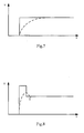
- an output voltage of a data line is shown in the solid line in Fig.7
- a driving voltage for a pixel unit is shown in the dashed line in Fig.7
- the driving circuit provided in the second embodiment the present disclosure is utilized, the output voltage of the driving circuit is shown in the solid line in Fig.8 , and the driving voltage for the pixel unit is shown in the dashed line in Fig.8 . It can be seen that when the driving circuit provided in the second embodiment of the present disclosure is utilized, the missing in the leading portion of the driving voltage for the pixel unit can be compensated.
- a display panel comprising the above driving circuit.
- the display panel is a TFT-LCD display panel.
- the driving circuit comprises a voltage dividing module, a comparing module and a switching module, wherein the voltage dividing module has a first terminal connected to a first terminal of the switching module, a second terminal connected to a first terminal of the comparing module, and a third terminal as a grounding terminal; the voltage dividing module receives an output voltage of the switching module, and outputs a feedback voltage to the comparing module after dividing the output voltage; a second terminal of the comparing module is connected to the first voltage input terminal, third, fourth and fifth terminals of the comparing module are connected to three control terminals of the switching module respectively; the comparing module outputs control signals to the switching module according to the comparison of the feedback voltage and a first voltage so that the switching module outputs a voltage equal to the first voltage when the feedback voltage is equal to the first voltage, wherein the first voltage is a target driving voltage; the first terminal of the switching module is connected to a voltage output terminal, a second terminal of the switching module is connected to the first voltage
Abstract
Description
- The present disclosure relates to the field of electronics technique, particularly to a driving circuit and a display panel.
- Currently, high-speed large-size Thin Film Transistor-Liquid Crystal Display TFT-LCD products have high requirements on driving voltages for pixel units. In the prior art, the driving voltages are supplied directly from data lines to individual pixel units in the TFT-LCD; however, in the TFT-LCD products, since the pixel units have resistive-capacitive loads, and the driving voltages received by the pixel units during an initial period in which the TFT-LCD products are powered on are often lower than voltages output from the data lines, that is, a leading portion of the driving voltages for the pixel units is missing. Especially in large-size LCD products, the voltages along the data line direction will decrease from top to bottom, which results in inaccuracy in grayscale displayed by the pixel units and in turn poor image quality.
- In embodiments of the present disclosure, there are provided a driving circuit and a display panel for alleviating the issue of the missing in the leading portion of the driving voltage for the pixel unit.
- According to an embodiment of the present disclosure, there is provided a driving circuit comprising a voltage dividing module, a comparing module and a switching module, wherein
- a first terminal of the voltage dividing module is connected to a first terminal of the switching module, a second terminal of the voltage dividing module is connected to a first terminal of the comparing module, and a third terminal of the voltage dividing module serves as a grounding terminal; the voltage dividing module receives an output voltage of the switching module, and outputs a feedback voltage to the comparing module after dividing the output voltage;
- a second terminal of the comparing module is connected to a first voltage input terminal, third, fourth and fifth terminals of the comparing module are connected to three control terminals of the switching module respectively; the comparing module outputs control signals to the switching module according to the comparison of the feedback voltage and a first voltage input from the first voltage input terminal so that the switching module outputs a voltage equal to the first voltage when the feedback voltage is equal to the first voltage, wherein the first voltage is a target driving voltage;
- a first terminal of the switching module is connected to a voltage output terminal, a second terminal of the switching module is connected to the first voltage input terminal, a third terminal of the switching module is connected to a second voltage input terminal, and a fourth terminal of the switching module is connected to a third voltage input terminal; the switching module controls its own state according to the control signals output from the comparing module so as to output a voltage to the voltage output terminal.
- According to another embodiment of the present disclosure, there is further provided a driving circuit comprising a voltage dividing module, a comparing module, a switching module and a voltage stabilizing module; wherein
- a first terminal of the voltage dividing module is connected to a first terminal of the voltage stabilizing module, a second terminal of the voltage dividing module is connected to a first terminal of the comparing module, and a third terminal of the voltage dividing module serves as a grounding terminal; the voltage dividing module receives an output voltage of the voltage stabilizing module, and outputs a feedback voltage to the comparing module after dividing the output voltage;
- a second terminal of the comparing module is connected to a first voltage input terminal, third, fourth and fifth terminals of the comparing module are connected to three control terminals of the switching module respectively; the comparing module outputs control signals to the switching module according to the comparison of the feedback voltage and a first voltage input from the first voltage input terminal so that the switching module outputs a voltage equal to the first voltage when the feedback voltage is equal to the first voltage, wherein the first voltage is a target driving voltage;
- a first terminal of the switching module is connected to a second terminal of the voltage stabilizing module, a second terminal of the switching module is connected to the first voltage input terminal, a third terminal of the switching module is connected to a second voltage input terminal, and a fourth terminal of the switching module is connected to a third voltage input terminal; the switching module controls its own state according to the control signals output from the comparing module so as to output a voltage to the voltage stabilizing module; and
- the first terminal of the voltage stabilizing module is connected to a voltage output terminal; the voltage stabilizing module stabilizes the output voltage of the switching module and outputs a stabilized voltage to the voltage output terminal.
- According to another embodiment of the present disclosure, there is further provided a display panel comprising the above driving circuit.
- In the driving circuit provided in the embodiments of the present disclosure, after the circuit is powered on, the output voltage of the switching module is controlled to equal to a target driving voltage only when the feedback voltage is equal to the target driving voltage; since the feedback voltage is a voltage divided from the output voltage of the circuit, that is, the feedback voltage is less than the output voltage of the circuit, the feedback voltage is controlled to equal to the target driving voltage during the initial period in which the circuit is powered on, so that the output voltage of the circuit is higher than the target driving voltage. That is, the missing in the leading portion of the driving voltage for pixel unit is compensated by means of overdriving.
- The accompanying drawings are provided to aid a further understanding of the present disclosure, and constitute a part of the specification, for illustrating the present disclosure together with the embodiments of the present disclosure, and not for making any limitation on the present disclosure.
-
Fig. 1 is a structure diagram illustrating a driving circuit provided in a first embodiment of the present disclosure; -
Fig. 2 is a detailed structure diagram illustrating the driving circuit provided in the first embodiment of the present disclosure; -
Fig. 3 is a structure diagram illustrating a driving circuit provided in a second embodiment of the present disclosure; -
Fig. 4 is a detailed structure diagram illustrating the driving circuit provided in the second embodiment of the present disclosure; -
Fig. 5 is a structure diagram illustrating a LCD apparatus provided in an embodiment of the present disclosure; -
Fig. 6 is a schematic diagram showing a logic control flow for generating control signals provided in an embodiment of the present disclosure; -
Fig. 7 is a schematic diagram showing a driving voltage for a pixel unit in the prior art; and -
Fig. 8 is a schematic diagram showing a driving voltage for a pixel unit provided in an embodiment of the present disclosure. - In order to provide an implementation for compensating the missing in the leading portion of the driving voltage for the pixel unit, a driving circuit and a display panel are provided in embodiments of the present disclosure. Hereinafter, the preferable embodiments of the present disclosure are described with reference to the accompanying drawings. It should be appreciated that the preferable embodiments of the present disclosure are only for illustrating the present disclosure, and are not intended to limit the scope of the present disclosure in any way. Further, throughout the specification, the technical features in an embodiment can be combined with the technical features in another embodiment without conflicting with each other.
- In the first embodiment of the present disclosure, there is provided a driving circuit connected between a data line and a TFT-LCD, and as shown in
Fig. 1 , the driving circuit comprises avoltage dividing module 11, acomparing module 12 and aswitching module 13. - The
voltage dividing module 11 has afirst terminal 111 connected to afirst terminal 131 of theswitching module 13, asecond terminal 112 connected to afirst terminal 121 of thecomparing module 12, and athird terminal 131 as a grounding terminal. Asecond terminal 122 of thecomparing module 12 is connected to a first voltage input terminal, and third, fourth andfifth terminals comparing module 12 are connected to three control terminals of theswitching module 13 respectively. Thefirst terminal 131 of theswitching module 13 is connected to a voltage output terminal, asecond terminal 132 of theswitching module 13 is connected to the first voltage input terminal, athird terminal 133 of theswitching module 13 is connected to a second voltage input terminal, and afourth terminal 134 of theswitching module 13 is connected to a third voltage input terminal. - The
voltage dividing module 11 receives an output voltage Vo of theswitching module 13, and outputs a feedback voltage Vf to thecomparing module 12 after dividing the output voltage Vo; thecomparing module 12 outputs control signals to theswitching module 13 according to the comparison of the feedback voltage Vf and a first voltage Vi input from the first voltage input terminal, so that theswitching module 13 outputs a voltage Vo equal to the first voltage Vi when the feedback voltage Vf is equal to the first voltage Vi, wherein the first voltage Vi is a target driving voltage; theswitching module 13 controls its own state according to the control signals output from thecomparing module 12 so as to output a voltage to the voltage output terminal. - The detailed structure of the driving circuit provided in the first embodiment of the present disclosure is illustrated in
Fig.2 . - In particular, the voltage dividing
module 11 can comprise a structure formed by a first resistor R1 and a second resistor R2 connected in series, two terminals of the structure serve thefirst terminal 111 and thethird terminal 113 of the voltage dividingmodule 11 respectively, and the point where the first resistor R1 and the second resistor R2 are connected serves as thesecond terminal 112 of the voltage dividingmodule 11. - In particular, the
switching module 13 can comprise a first switch S1, a second switch S2, and a third switch S3, wherein: - a first terminal of the first switch S1, a first terminal of the second switch S2, and a first terminal of the third switch S3 serve as the three control terminals of the
switching module 13; a second terminal of the first switch S1, a second terminal of the second switch S2 and a second terminal of the third switch S3 are connected together for severing as thefirst terminal 131 of theswitching module 13; a third terminal of the third switch S3 severs as thesecond terminal 132 of theswitching module 13; a third terminal of the first switch S1 severs as thethird terminal 133 of theswitching module 13; and a third terminal of the second switch S2 severs as thefourth terminal 134 of theswitching module 13. - The
comparing module 12 can be of any controllable logic circuit, and the structure thereof is not described in detail herein. When a second voltage Vgh input from the second voltage input terminal is greater than the first voltage Vi and the first voltage Vi is greater than a third voltage Vgl input from the third voltage input terminal, the logic control flow for generating the control signals is as follows. - When the feedback voltage Vf is lower than the first voltage Vi, the
comparing module 12 outputs control signals to close the first switch S1 and to open the second switch S2 and the third switch S3; when the feedback voltage Vf is greater than the first voltage Vi, thecomparing module 12 outputs control signals to close the second switch S2 and to open the first switch S1 and the third switch S3; when the feedback voltage Vf is equal to the first voltage Vi, thecomparing module 12 outputs control signals to close the third switch S3 and to open the first switch S1 and the second switch S2. - When the driving circuit is powered on, the
comparing module 12 receives the feedback voltage Vf output from the voltage dividingmodule 11 and the first voltage Vi, and outputs control signals according to the logic control flow described above; theswitching module 13 closes or opens the individual switches according to the control signals so as to adjust the feedback voltage Vf to make it equal to the first voltage Vi; during the phase, theswitching module 13 closes the first switch S1 and opens the second switch S2 and the third switch S3, and a voltage Vo output from the driving circuit is higher than the first voltage Vi; when the feedback voltage Vf is equal to the first voltage Vi, thecomparing module 12 outputs control signals to theswitching module 13 so that the latter closes the third switch S3 and opens the first switch S1 and the second switch S2, and at this time, the voltage Vo output from the driving circuit is equal to the first voltage Vi. - It can be seen that in the driving circuit provided in the present embodiment of the present disclosure, the missing in the leading portion of the driving voltage for the pixel unit is compensated by means of the overdriving principle. Nevertheless, in practice, there may be a case in which the output voltage of the switching module might be unstable. Preferably, a voltage stabilizing module can be arranged after the switching module to improve the performance of the driving circuit.
- In the second embodiment of the present disclosure, there is provided a driving circuit connected between a data line and a TFT-LCD, and as shown in
Fig. 3 , the driving circuit comprises avoltage dividing module 11, acomparing module 12, aswitching module 13 and avoltage stabilizing module 34. - The
voltage dividing module 11 has afirst terminal 111 connected to afirst terminals 341 of thevoltage stabilizing module 34, asecond terminal 112 connected to afirst terminal 121 of thecomparing module 12, and athird terminal 113 as a grounding terminal. Asecond terminal 122 of thecomparing module 12 is connected to a first voltage input terminal, and third, fourth andfifth terminals comparing module 12 are connected to three control terminals of theswitching module 13 respectively. Afirst terminal 131 of theswitching module 13 is connected to asecond terminal 342 of thevoltage stabilizing module 34, asecond terminal 132 of theswitching module 13 is connected to the first voltage input terminal, athird terminal 133 of theswitching module 13 is connected to a second voltage input terminal, and afourth terminal 134 of theswitching module 13 is connected to a third voltage input terminal. Thefirst terminal 341 of thevoltage stabilizing module 34 is connected to a voltage output terminal. - The
voltage dividing module 11 receives an output voltage Vo of thevoltage stabilizing module 34, and outputs a feedback voltage Vf to thecomparing module 12 after dividing the output voltage Vo; thecomparing module 12 outputs control signals to theswitching module 13 according to the comparison of the feedback voltage Vf and a first voltage Vi input from the first voltage input terminal, so that theswitching module 13 outputs a voltage Vo equal to the first voltage Vi when the feedback voltage Vf is equal to the first voltage Vi, wherein the first voltage Vi is a target driving voltage; theswitching module 13 controls its own state according to the control signals output from thecomparing module 12 so as to output a voltage to thevoltage stabilizing module 34; thevoltage stabilizing module 34 stabilizes the output voltage of theswitching module 13 and outputs a stabilized voltage to the voltage output terminal. - The detailed structure of the driving circuit provided in the second embodiment of the present disclosure is illustrated in
Fig. 4 . - In particular, the voltage dividing
module 11 can comprise a structure formed by a first resistor R1 and a second resistor R2 connected in series, two terminals of the structure serve thefirst terminal 111 and thethird terminal 113 of thevoltage dividing module 11 respectively, the point where the first resistor R1 and the second resistor R2 are connected serves as thesecond terminal 112 of the voltage dividingmodule 11. - In particular, the
switching module 13 can comprise a first switch S1, a second switch S2, and a third switch S3, wherein: - a first terminal of the first switch S1, a first terminal of the second switch S2, and a first terminal of the third switch S3 serve as the three control terminals of the
switching module 13; a second terminal of the first switch S1, a second terminal of the second switch S2 and a second terminal of the third switch S3 are connected together for severing as thefirst terminal 131 of theswitching module 13; a third terminal of the third switch S3 severs as thesecond terminal 132 of theswitching module 13; a third terminal of the first switch S1 severs as thethird terminal 133 of theswitching module 13; a third terminal of the second switch S2 severs as thefourth terminal 134 of theswitching module 13. - Specifically, the
voltage stabilizing module 34 can be an operational amplifier K, wherein an output terminal of the operational amplifier K severs as thefirst terminal 341 of thevoltage stabilizing module 34, a non-inverting input terminal of the operational amplifier K severs as thesecond terminal 342 of thevoltage stabilizing module 34, and an inverting input terminal of the operational amplifier K is connected to the output terminal of the operational amplifier K. - The
comparing module 12 can be of any controllable logic circuit, and the structure thereof is not described in detail herein. When a second voltage Vgh input from the second voltage input terminal is greater than the first voltage Vi and the first voltage Vi is greater than a third voltage Vgl input from the third voltage input terminal, the logic control flow for generating the control signals is as follows. - When the feedback voltage Vf is lower than the first voltage Vi, the comparing
module 12 outputs control signals to close the first switch S1 and to open the second switch S2 and the third switch S3; when the feedback voltage Vf is greater than the first voltage Vi, the comparingmodule 12 outputs control signals to close the second switch S2 and to open the first switch S1 and the third switch S3; when the feedback voltage Vf is equal to the first voltage Vi, the comparingmodule 12 outputs control signals to close the third switch S3 and to open the first switch S1 and the second switch S2. - In the driving circuit provided in the second embodiment of the present disclosure, a voltage stabilizing module is added on the basis of the driving circuit provided in the first embodiment of the present disclosure, and the operating principle of the driving circuit provided in the second embodiment of the present disclosure is similar to that in the first embodiment of the present disclosure, and the details are omitted.
- In practice, the driving circuit provided in first embodiment or in the second embodiment of the present disclosure can be used in a LCD apparatus comprising a gate driving circuit, a source driving circuit and a display panel, as shown in
Fig. 5 . The display panel includes gate lines and data lines crossing each other, and individual pixel units formed at the intersections of the gate lines and the data lines. One TFT is arranged in each pixel unit. Particularly, the gate driving circuit is connected with a plurality of gate lines, for supplying the gate lines with the voltages for turning on the gates of the transistors and the voltages for turning off the gates of the transistors, and for controlling the TFTs in the pixel units to be turned on or turned off. Particularly, the source driving circuit is connected with a plurality of data lines, for supplying each pixel unit with a data signal. As the voltage is transmitted from top to bottom, the voltage along the data line direction will decrease from top to bottom due to the resistive-capacitive load of the pixel unit. - In the LCD apparatus utilizing the driving circuit provided in the embodiments of the present disclosure, the first voltage input terminal can be connected to an output terminal for a data signal of the source driving circuit, that is, the uppermost end of the data line (a case in which the data signal is transmitted from top to bottom is taken as example); the second voltage input terminal can receive the voltage for turning on the gate of the transistor, and the third voltage input terminal can receive the voltage for turning off the gate of the transistor. The voltage output terminal is connected to the data line where the pixel unit locates. Thus, the voltage of each pixel unit in realtime can be fed back to the comparing
module 12 via the feedback voltage Vf output from a feedback terminal; and the feedback voltage Vf is compared to the first voltage Vi in realtime, and the comparingmodule 12 outputs control signals to theswitching module 13 according to the comparison of the feedback voltage Vf and the first voltage Vi. - When the feedback voltage Vf is less than the first voltage Vi, it is indicated that it is necessary to increase the output voltage of the voltage output terminal, so as to drive the pixel unit much better. At this time, the comparing module outputs control signals to close the first switch S1 and to open the second switch S2 and the third switch S3. At this time, the first switch S1 can provide a higher voltage Vgh, so that the output voltage Vo of the voltage output terminal increases, and thus the pixel unit is driven much better; when the feedback voltage Vf is greater than the first voltage Vi, it is indicated that it is necessary to decrease the output voltage Vo of the voltage output terminal, so as to drive the pixel unit much better. At this time, the comparing module outputs control signals to close the second switch S2 and open the first switch S1 and the third switch S3. At this time, the second switch S2 can provide a lower voltage Vgl, so that the output voltage Vo of the voltage output terminal decreases, and thus the pixel unit is driven much better; when the feedback voltage Vf is equal to the first voltage Vi, the comparing module outputs control signals to close the third switch S3 and to open the
first switch S 1 and the second switch S2. Since the third switch S3 is connected to the first voltage Vi, the pixel unit can be driven much better without processing the output voltage Vo. - When generating the control signals for switches, a frame start signal YDIO and a polarity control signal Pol can also be considered, and at this time, the control flow for the switches is shown in
Figure 6 . - It can be seen that, in the embodiments of the present disclosure, the driving circuit compensates the data lines of the TFT-LCD by means of the overdriving principle so as to increase the initial voltage to complement the missing in the leading portion of the voltage, thus improving the image quality. The driving circuit controls the output timing of individual voltages by the comparing module, and the length of time of individual voltages depends on when the feedback voltage Vf is adjusted to equal to the first voltage Vi; the length of time of individual voltages is adjusted, so that, when a same driving voltage is applied, the column of pixels render a grayscale which is consistent with that in other regions, thus improving the image quality.
- In an embodiment of the present disclosure, an amplification factor is adjusted according to the serial number of a gate line and the polarity of the voltage (POL_reg represents the polarity), so as to complement the missing in the leading portion of the voltage, thereby improving the image quality.
- In the prior art, an output voltage of a data line is shown in the solid line in
Fig.7 , and a driving voltage for a pixel unit is shown in the dashed line inFig.7 ; when the driving circuit provided in the second embodiment the present disclosure is utilized, the output voltage of the driving circuit is shown in the solid line inFig.8 , and the driving voltage for the pixel unit is shown in the dashed line inFig.8 . It can be seen that when the driving circuit provided in the second embodiment of the present disclosure is utilized, the missing in the leading portion of the driving voltage for the pixel unit can be compensated. - According to another embodiment of the present disclosure, there is further provided a display panel comprising the above driving circuit.
- Further, the display panel is a TFT-LCD display panel.
- In Summary, the driving circuit provided in the embodiments of the present disclosure comprises a voltage dividing module, a comparing module and a switching module, wherein the voltage dividing module has a first terminal connected to a first terminal of the switching module, a second terminal connected to a first terminal of the comparing module, and a third terminal as a grounding terminal; the voltage dividing module receives an output voltage of the switching module, and outputs a feedback voltage to the comparing module after dividing the output voltage; a second terminal of the comparing module is connected to the first voltage input terminal, third, fourth and fifth terminals of the comparing module are connected to three control terminals of the switching module respectively; the comparing module outputs control signals to the switching module according to the comparison of the feedback voltage and a first voltage so that the switching module outputs a voltage equal to the first voltage when the feedback voltage is equal to the first voltage, wherein the first voltage is a target driving voltage; the first terminal of the switching module is connected to a voltage output terminal, a second terminal of the switching module is connected to the first voltage input terminal, a third terminal of the switching module is connected to the second voltage input terminal, and a fourth terminal of the switching module is connected to the third voltage input terminal; the switching module controls its own state according to the control signals output from the comparing module so as to output a voltage to the voltage output terminal. The missing in the leading portion of the driving voltage for the pixel unit can be compensated by use of the driving circuit provided in the embodiments of the present disclosure.
- Obviously, those skilled in the art can make various modifications and variations on the embodiments of the present disclosure without departing from the spirit and scope of the invention. Thus, provided that these modifications and variations belong to the scope of the claims and their equivalences, the present disclosure is also intended to include these modifications and variations.
Claims (9)
- A driving circuit comprising a voltage dividing module, a comparing module and a switching module, wherein
a first terminal of the voltage dividing module is connected to a first terminal of the switching module, a second terminal of the voltage dividing module is connected to a first terminal of the comparing module, and a third terminal of the voltage dividing module serves as a grounding terminal; the voltage dividing module receives an output voltage of the switching module, and outputs a feedback voltage to the comparing module after dividing the output voltage;
a second terminal of the comparing module is connected to a first voltage input terminal, third, fourth and fifth terminals of the comparing module are connected to three control terminals of the switching module respectively; the comparing module outputs control signals to the switching module according to a comparison of the feedback voltage and a first voltage input from the first voltage input terminal so that the switching module outputs a voltage equal to the first voltage when the feedback voltage is equal to the first voltage, wherein the first voltage is a target driving voltage;
the first terminal of the switching module is connected to a voltage output terminal, a second terminal of the switching module is connected to the first voltage input terminal, a third terminal of the switching module is connected to a second voltage input terminal, and a fourth terminal of the switching module is connected to a third voltage input terminal; the switching module controls its own state according to the control signals output from the comparing module so as to output a voltage to the voltage output terminal. - The driving circuit of claim 1, wherein the voltage dividing module comprises a structure formed by a first resistor and a second resistor connected in series, two terminals of the structure serve the first terminal and the third terminal of the voltage dividing module respectively, and a point where the first resistor and the second resistor are connected serves as the second terminal of the voltage dividing module.
- The driving circuit of claim 1, wherein the switching module comprises a first switch, a second switch, and a third switch, wherein:a first terminal of the first switch, a first terminal of the second switch, and a first terminal of the third switch serve as the three control terminals of the switching module;a second terminal of the first switch, a second terminal of the second switch and a second terminal of the third switch are connected together for severing as the first terminal of the switching module;a third terminal of the third switch severs as the second terminal of the switching module;a third terminal of the first switch severs as the third terminal of the switching module; anda third terminal of the second switch severs as the fourth terminal of the switching module.
- A driving circuit comprising a voltage dividing module, a comparing module, a switching module and a voltage stabilizing module; wherein
a first terminal of the voltage dividing module is connected to a first terminal of the voltage stabilizing module, a second terminal of the voltage dividing module is connected to a first terminal of the comparing module, and a third terminal of the voltage dividing module serves as a grounding terminal; the voltage dividing module receives an output voltage of the voltage stabilizing module, and outputs a feedback voltage to the comparing module after dividing the output voltage;
a second terminal of the comparing module is connected to a first voltage input terminal, third, fourth and fifth terminals of the comparing module are connected to three control terminals of the switching module respectively; the comparing module outputs control signals to the switching module according to a comparison of the feedback voltage and a first voltage input from the first voltage input terminal so that the switching module outputs a voltage equal to the first voltage when the feedback voltage is equal to the first voltage, wherein the first voltage is a target driving voltage;
a first terminal of the switching module is connected to a second terminal of the voltage stabilizing module, a second terminal of the switching module is connected to the first voltage input terminal, a third terminal of the switching module is connected to a second voltage input terminal, and a fourth terminal of the switching module is connected to a third voltage input terminal; the switching module controls its own state according to the control signals output from the comparing module so as to output a voltage to the voltage stabilizing module; and
the first terminal of the voltage stabilizing module is connected to a voltage output terminal; the voltage stabilizing module stabilizes the output voltage of the switching module and outputs the stabilized voltage to the voltage output terminal. - The driving circuit of claim 4, wherein the voltage dividing module comprises a structure formed by a first resistor and a second resistor connected in series, two terminals of the structure serve the first terminal and the third terminal of the voltage dividing module respectively, and a point where the first resistor and the second resistor are connected serves as the second terminal of the voltage dividing module.
- The driving circuit of claim 4, wherein the switching module comprises a first switch, a second switch, and a third switch, wherein:a first terminal of the first switch, a first terminal of the second switch, and a first terminal of the third switch serve as the three control terminals of the switching module;a second terminal of the first switch, a second terminal of the second switch and a second terminal of the third switch are connected together for severing as the first terminal of the switching module;a third terminal of the third switch severs as the second terminal of the switching module;a third terminal of the first switch severs as the third terminal of the switching module; anda third terminal of the second switch severs as the fourth terminal of the switching module.
- The driving circuit of claim 4, wherein the voltage stabilizing module is an operational amplifier, an output terminal of the operational amplifier severs as the first terminal of the voltage stabilizing module, a non-inverting input terminal of the operational amplifier severs as the second terminal of the voltage stabilizing module, and an inverting input terminal of the operational amplifier is connected to the output terminal of the operational amplifier.
- A display panel comprising the driving circuit of any one of claims 1-7.
- The display panel of claim 8, wherein the display panel is a Thin Film Transistor Liquid Crystal Display panel.
Applications Claiming Priority (1)
| Application Number | Priority Date | Filing Date | Title |
|---|---|---|---|
| CN201210546131.0A CN103021317B (en) | 2012-12-14 | 2012-12-14 | Driving circuit and display screen |
Publications (3)
| Publication Number | Publication Date |
|---|---|
| EP2743914A2 true EP2743914A2 (en) | 2014-06-18 |
| EP2743914A3 EP2743914A3 (en) | 2014-09-03 |
| EP2743914B1 EP2743914B1 (en) | 2016-06-15 |
Family
ID=47969859
Family Applications (1)
| Application Number | Title | Priority Date | Filing Date |
|---|---|---|---|
| EP13197077.4A Active EP2743914B1 (en) | 2012-12-14 | 2013-12-13 | Driving circuit and display panel |
Country Status (3)
| Country | Link |
|---|---|
| US (1) | US9330626B2 (en) |
| EP (1) | EP2743914B1 (en) |
| CN (1) | CN103021317B (en) |
Families Citing this family (2)
| Publication number | Priority date | Publication date | Assignee | Title |
|---|---|---|---|---|
| CN105139824B (en) * | 2015-10-16 | 2018-02-06 | 重庆京东方光电科技有限公司 | Gate drivers and its configuration system and regulating allocation method |
| CN107527594B (en) * | 2017-09-22 | 2020-02-21 | 昆山龙腾光电股份有限公司 | Pulse signal adjusting circuit and backlight driving circuit of liquid crystal display screen |
Citations (2)
| Publication number | Priority date | Publication date | Assignee | Title |
|---|---|---|---|---|
| WO2005057545A1 (en) * | 2003-12-08 | 2005-06-23 | Koninklijke Philips Electronics N.V. | Display device driving circuit |
| US20100182307A1 (en) * | 2009-01-21 | 2010-07-22 | Himax Technologies Limited | Output buffering circuit, amplifier device, and display device with reduced power consumption |
Family Cites Families (9)
| Publication number | Priority date | Publication date | Assignee | Title |
|---|---|---|---|---|
| US5627460A (en) * | 1994-12-28 | 1997-05-06 | Unitrode Corporation | DC/DC converter having a bootstrapped high side driver |
| US5867136A (en) * | 1995-10-02 | 1999-02-02 | Micron Display Technology, Inc. | Column charge coupling method and device |
| CN100552593C (en) * | 2004-02-05 | 2009-10-21 | 美国芯源系统股份有限公司 | Voltage regulator and method thereof |
| JP2007011947A (en) * | 2005-07-04 | 2007-01-18 | Toshiba Microelectronics Corp | Power source regulator circuit |
| JP4984997B2 (en) * | 2007-03-16 | 2012-07-25 | 富士通セミコンダクター株式会社 | DC-DC converter control circuit, power supply voltage supply system, and power supply voltage supply method |
| US7973518B2 (en) * | 2008-06-05 | 2011-07-05 | Intel Corporation | Low noise voltage regulator |
| KR101221583B1 (en) * | 2009-12-28 | 2013-01-14 | 엘지디스플레이 주식회사 | Back Light Unit, Method for Driving The Same, and Liquid Crystal Display Device Using The Same |
| JP5811699B2 (en) * | 2011-08-31 | 2015-11-11 | 富士通株式会社 | DC-DC converter |
| US8988054B2 (en) * | 2011-12-27 | 2015-03-24 | St-Ericsson Sa | Single feedback loop for parallel architecture buck converter—LDO regulator |
-
2012
- 2012-12-14 CN CN201210546131.0A patent/CN103021317B/en active Active
-
2013
- 2013-12-13 EP EP13197077.4A patent/EP2743914B1/en active Active
- 2013-12-13 US US14/105,468 patent/US9330626B2/en active Active
Patent Citations (2)
| Publication number | Priority date | Publication date | Assignee | Title |
|---|---|---|---|---|
| WO2005057545A1 (en) * | 2003-12-08 | 2005-06-23 | Koninklijke Philips Electronics N.V. | Display device driving circuit |
| US20100182307A1 (en) * | 2009-01-21 | 2010-07-22 | Himax Technologies Limited | Output buffering circuit, amplifier device, and display device with reduced power consumption |
Also Published As
| Publication number | Publication date |
|---|---|
| EP2743914A3 (en) | 2014-09-03 |
| CN103021317A (en) | 2013-04-03 |
| EP2743914B1 (en) | 2016-06-15 |
| US20140168046A1 (en) | 2014-06-19 |
| US9330626B2 (en) | 2016-05-03 |
| CN103021317B (en) | 2015-09-09 |
Similar Documents
| Publication | Publication Date | Title |
|---|---|---|
| US9875706B1 (en) | GOA circuit of reducing feed-through voltage | |
| US8248398B2 (en) | Device and method for driving liquid crystal display device | |
| KR101362153B1 (en) | Liquid crystal display device and method for driving the same | |
| US20080316159A1 (en) | Liquid crystal display device with scanning controlling circuit and driving method thereof | |
| KR20080053599A (en) | Liquid crystal display | |
| US10748501B2 (en) | Gate driver, display panel and display using same | |
| US9078301B2 (en) | Output stage circuit for gate driving circuit in LCD | |
| US10885867B2 (en) | Driving method for display device and related driving device | |
| US10510291B2 (en) | Display method and display device | |
| US9842552B2 (en) | Data driving circuit, display device and driving method thereof | |
| US10347200B2 (en) | Liquid crystal display device with time sequence controller circuit switching off and on an interior analog circuit of the source driver | |
| US9905149B2 (en) | Driving circuit, driving method, and display device | |
| KR101241139B1 (en) | Liquid display device and driving method the same | |
| US9330626B2 (en) | Driving circuit and display panel | |
| US9423637B2 (en) | Display device including data signal line drive circuit | |
| KR20070080952A (en) | Data modulation device, liquid crystal display device having the same and method for driving the same | |
| KR20070064733A (en) | Ips mode liquid crystal display | |
| US20140340291A1 (en) | Chamfered Circuit and Control Method Thereof | |
| KR20140123625A (en) | Liquid crystal display device of ultra high definition and method for driving the same | |
| US20150161959A1 (en) | Driving Method and Driving Device thereof | |
| US20110037743A1 (en) | Driver Circuit for Dot Inversion of Liquid Crystals | |
| KR20040071507A (en) | Liquid Crystal Display Device | |
| US20100315405A1 (en) | Driving circuit for liquid crystal display device | |
| US9928800B2 (en) | Display apparatus and a method of driving the same | |
| KR20060118702A (en) | Liquid crystal display device |
Legal Events
| Date | Code | Title | Description |
|---|---|---|---|
| PUAI | Public reference made under article 153(3) epc to a published international application that has entered the european phase |
Free format text: ORIGINAL CODE: 0009012 |
|
| 17P | Request for examination filed |
Effective date: 20131213 |
|
| AK | Designated contracting states |
Kind code of ref document: A2 Designated state(s): AL AT BE BG CH CY CZ DE DK EE ES FI FR GB GR HR HU IE IS IT LI LT LU LV MC MK MT NL NO PL PT RO RS SE SI SK SM TR |
|
| AX | Request for extension of the european patent |
Extension state: BA ME |
|
| PUAL | Search report despatched |
Free format text: ORIGINAL CODE: 0009013 |
|
| AK | Designated contracting states |
Kind code of ref document: A3 Designated state(s): AL AT BE BG CH CY CZ DE DK EE ES FI FR GB GR HR HU IE IS IT LI LT LU LV MC MK MT NL NO PL PT RO RS SE SI SK SM TR |
|
| AX | Request for extension of the european patent |
Extension state: BA ME |
|
| RIC1 | Information provided on ipc code assigned before grant |
Ipc: H02M 3/156 20060101ALI20140728BHEP Ipc: H03K 6/02 20060101ALI20140728BHEP Ipc: H02M 1/00 20070101ALI20140728BHEP Ipc: H02M 3/06 20060101ALI20140728BHEP Ipc: G09G 3/36 20060101AFI20140728BHEP |
|
| R17P | Request for examination filed (corrected) |
Effective date: 20150302 |
|
| RBV | Designated contracting states (corrected) |
Designated state(s): AL AT BE BG CH CY CZ DE DK EE ES FI FR GB GR HR HU IE IS IT LI LT LU LV MC MK MT NL NO PL PT RO RS SE SI SK SM TR |
|
| 17Q | First examination report despatched |
Effective date: 20150625 |
|
| GRAP | Despatch of communication of intention to grant a patent |
Free format text: ORIGINAL CODE: EPIDOSNIGR1 |
|
| INTG | Intention to grant announced |
Effective date: 20160128 |
|
| GRAS | Grant fee paid |
Free format text: ORIGINAL CODE: EPIDOSNIGR3 |
|
| GRAA | (expected) grant |
Free format text: ORIGINAL CODE: 0009210 |
|
| AK | Designated contracting states |
Kind code of ref document: B1 Designated state(s): AL AT BE BG CH CY CZ DE DK EE ES FI FR GB GR HR HU IE IS IT LI LT LU LV MC MK MT NL NO PL PT RO RS SE SI SK SM TR |
|
| REG | Reference to a national code |
Ref country code: CH Ref legal event code: EP Ref country code: GB Ref legal event code: FG4D |
|
| REG | Reference to a national code |
Ref country code: IE Ref legal event code: FG4D |
|
| REG | Reference to a national code |
Ref country code: AT Ref legal event code: REF Ref document number: 806843 Country of ref document: AT Kind code of ref document: T Effective date: 20160715 |
|
| REG | Reference to a national code |
Ref country code: DE Ref legal event code: R096 Ref document number: 602013008555 Country of ref document: DE |
|
| REG | Reference to a national code |
Ref country code: NL Ref legal event code: FP |
|
| REG | Reference to a national code |
Ref country code: LT Ref legal event code: MG4D |
|
| PG25 | Lapsed in a contracting state [announced via postgrant information from national office to epo] |
Ref country code: NO Free format text: LAPSE BECAUSE OF FAILURE TO SUBMIT A TRANSLATION OF THE DESCRIPTION OR TO PAY THE FEE WITHIN THE PRESCRIBED TIME-LIMIT Effective date: 20160915 Ref country code: LT Free format text: LAPSE BECAUSE OF FAILURE TO SUBMIT A TRANSLATION OF THE DESCRIPTION OR TO PAY THE FEE WITHIN THE PRESCRIBED TIME-LIMIT Effective date: 20160615 Ref country code: FI Free format text: LAPSE BECAUSE OF FAILURE TO SUBMIT A TRANSLATION OF THE DESCRIPTION OR TO PAY THE FEE WITHIN THE PRESCRIBED TIME-LIMIT Effective date: 20160615 |
|
| REG | Reference to a national code |
Ref country code: FR Ref legal event code: PLFP Year of fee payment: 4 |
|
| REG | Reference to a national code |
Ref country code: AT Ref legal event code: MK05 Ref document number: 806843 Country of ref document: AT Kind code of ref document: T Effective date: 20160615 |
|
| PG25 | Lapsed in a contracting state [announced via postgrant information from national office to epo] |
Ref country code: GR Free format text: LAPSE BECAUSE OF FAILURE TO SUBMIT A TRANSLATION OF THE DESCRIPTION OR TO PAY THE FEE WITHIN THE PRESCRIBED TIME-LIMIT Effective date: 20160916 Ref country code: RS Free format text: LAPSE BECAUSE OF FAILURE TO SUBMIT A TRANSLATION OF THE DESCRIPTION OR TO PAY THE FEE WITHIN THE PRESCRIBED TIME-LIMIT Effective date: 20160615 Ref country code: SE Free format text: LAPSE BECAUSE OF FAILURE TO SUBMIT A TRANSLATION OF THE DESCRIPTION OR TO PAY THE FEE WITHIN THE PRESCRIBED TIME-LIMIT Effective date: 20160615 Ref country code: HR Free format text: LAPSE BECAUSE OF FAILURE TO SUBMIT A TRANSLATION OF THE DESCRIPTION OR TO PAY THE FEE WITHIN THE PRESCRIBED TIME-LIMIT Effective date: 20160615 Ref country code: LV Free format text: LAPSE BECAUSE OF FAILURE TO SUBMIT A TRANSLATION OF THE DESCRIPTION OR TO PAY THE FEE WITHIN THE PRESCRIBED TIME-LIMIT Effective date: 20160615 |
|
| PG25 | Lapsed in a contracting state [announced via postgrant information from national office to epo] |
Ref country code: IT Free format text: LAPSE BECAUSE OF FAILURE TO SUBMIT A TRANSLATION OF THE DESCRIPTION OR TO PAY THE FEE WITHIN THE PRESCRIBED TIME-LIMIT Effective date: 20160615 Ref country code: RO Free format text: LAPSE BECAUSE OF FAILURE TO SUBMIT A TRANSLATION OF THE DESCRIPTION OR TO PAY THE FEE WITHIN THE PRESCRIBED TIME-LIMIT Effective date: 20160615 Ref country code: IS Free format text: LAPSE BECAUSE OF FAILURE TO SUBMIT A TRANSLATION OF THE DESCRIPTION OR TO PAY THE FEE WITHIN THE PRESCRIBED TIME-LIMIT Effective date: 20161015 Ref country code: SK Free format text: LAPSE BECAUSE OF FAILURE TO SUBMIT A TRANSLATION OF THE DESCRIPTION OR TO PAY THE FEE WITHIN THE PRESCRIBED TIME-LIMIT Effective date: 20160615 Ref country code: EE Free format text: LAPSE BECAUSE OF FAILURE TO SUBMIT A TRANSLATION OF THE DESCRIPTION OR TO PAY THE FEE WITHIN THE PRESCRIBED TIME-LIMIT Effective date: 20160615 Ref country code: CZ Free format text: LAPSE BECAUSE OF FAILURE TO SUBMIT A TRANSLATION OF THE DESCRIPTION OR TO PAY THE FEE WITHIN THE PRESCRIBED TIME-LIMIT Effective date: 20160615 |
|
| PG25 | Lapsed in a contracting state [announced via postgrant information from national office to epo] |
Ref country code: BE Free format text: LAPSE BECAUSE OF FAILURE TO SUBMIT A TRANSLATION OF THE DESCRIPTION OR TO PAY THE FEE WITHIN THE PRESCRIBED TIME-LIMIT Effective date: 20160615 Ref country code: ES Free format text: LAPSE BECAUSE OF FAILURE TO SUBMIT A TRANSLATION OF THE DESCRIPTION OR TO PAY THE FEE WITHIN THE PRESCRIBED TIME-LIMIT Effective date: 20160615 Ref country code: PL Free format text: LAPSE BECAUSE OF FAILURE TO SUBMIT A TRANSLATION OF THE DESCRIPTION OR TO PAY THE FEE WITHIN THE PRESCRIBED TIME-LIMIT Effective date: 20160615 Ref country code: AT Free format text: LAPSE BECAUSE OF FAILURE TO SUBMIT A TRANSLATION OF THE DESCRIPTION OR TO PAY THE FEE WITHIN THE PRESCRIBED TIME-LIMIT Effective date: 20160615 Ref country code: SM Free format text: LAPSE BECAUSE OF FAILURE TO SUBMIT A TRANSLATION OF THE DESCRIPTION OR TO PAY THE FEE WITHIN THE PRESCRIBED TIME-LIMIT Effective date: 20160615 Ref country code: PT Free format text: LAPSE BECAUSE OF FAILURE TO SUBMIT A TRANSLATION OF THE DESCRIPTION OR TO PAY THE FEE WITHIN THE PRESCRIBED TIME-LIMIT Effective date: 20161017 |
|
| REG | Reference to a national code |
Ref country code: DE Ref legal event code: R097 Ref document number: 602013008555 Country of ref document: DE |
|
| PLBE | No opposition filed within time limit |
Free format text: ORIGINAL CODE: 0009261 |
|
| STAA | Information on the status of an ep patent application or granted ep patent |
Free format text: STATUS: NO OPPOSITION FILED WITHIN TIME LIMIT |
|
| 26N | No opposition filed |
Effective date: 20170316 |
|
| PG25 | Lapsed in a contracting state [announced via postgrant information from national office to epo] |
Ref country code: DK Free format text: LAPSE BECAUSE OF FAILURE TO SUBMIT A TRANSLATION OF THE DESCRIPTION OR TO PAY THE FEE WITHIN THE PRESCRIBED TIME-LIMIT Effective date: 20160615 |
|
| REG | Reference to a national code |
Ref country code: CH Ref legal event code: PL |
|
| REG | Reference to a national code |
Ref country code: DE Ref legal event code: R082 Ref document number: 602013008555 Country of ref document: DE Representative=s name: KLUNKER IP PATENTANWAELTE PARTG MBB, DE |
|
| PG25 | Lapsed in a contracting state [announced via postgrant information from national office to epo] |
Ref country code: SI Free format text: LAPSE BECAUSE OF FAILURE TO SUBMIT A TRANSLATION OF THE DESCRIPTION OR TO PAY THE FEE WITHIN THE PRESCRIBED TIME-LIMIT Effective date: 20160615 |
|
| PG25 | Lapsed in a contracting state [announced via postgrant information from national office to epo] |
Ref country code: MC Free format text: LAPSE BECAUSE OF FAILURE TO SUBMIT A TRANSLATION OF THE DESCRIPTION OR TO PAY THE FEE WITHIN THE PRESCRIBED TIME-LIMIT Effective date: 20160615 |
|
| REG | Reference to a national code |
Ref country code: IE Ref legal event code: MM4A |
|
| PG25 | Lapsed in a contracting state [announced via postgrant information from national office to epo] |
Ref country code: CH Free format text: LAPSE BECAUSE OF NON-PAYMENT OF DUE FEES Effective date: 20161231 Ref country code: LI Free format text: LAPSE BECAUSE OF NON-PAYMENT OF DUE FEES Effective date: 20161231 Ref country code: LU Free format text: LAPSE BECAUSE OF NON-PAYMENT OF DUE FEES Effective date: 20161213 |
|
| REG | Reference to a national code |
Ref country code: FR Ref legal event code: PLFP Year of fee payment: 5 |
|
| PG25 | Lapsed in a contracting state [announced via postgrant information from national office to epo] |
Ref country code: IE Free format text: LAPSE BECAUSE OF NON-PAYMENT OF DUE FEES Effective date: 20161213 |
|
| PG25 | Lapsed in a contracting state [announced via postgrant information from national office to epo] |
Ref country code: HU Free format text: LAPSE BECAUSE OF FAILURE TO SUBMIT A TRANSLATION OF THE DESCRIPTION OR TO PAY THE FEE WITHIN THE PRESCRIBED TIME-LIMIT; INVALID AB INITIO Effective date: 20131213 |
|
| PG25 | Lapsed in a contracting state [announced via postgrant information from national office to epo] |
Ref country code: MK Free format text: LAPSE BECAUSE OF FAILURE TO SUBMIT A TRANSLATION OF THE DESCRIPTION OR TO PAY THE FEE WITHIN THE PRESCRIBED TIME-LIMIT Effective date: 20160615 Ref country code: CY Free format text: LAPSE BECAUSE OF FAILURE TO SUBMIT A TRANSLATION OF THE DESCRIPTION OR TO PAY THE FEE WITHIN THE PRESCRIBED TIME-LIMIT Effective date: 20160615 |
|
| PG25 | Lapsed in a contracting state [announced via postgrant information from national office to epo] |
Ref country code: BG Free format text: LAPSE BECAUSE OF FAILURE TO SUBMIT A TRANSLATION OF THE DESCRIPTION OR TO PAY THE FEE WITHIN THE PRESCRIBED TIME-LIMIT Effective date: 20160615 |
|
| PG25 | Lapsed in a contracting state [announced via postgrant information from national office to epo] |
Ref country code: MT Free format text: LAPSE BECAUSE OF NON-PAYMENT OF DUE FEES Effective date: 20161213 |
|
| PG25 | Lapsed in a contracting state [announced via postgrant information from national office to epo] |
Ref country code: AL Free format text: LAPSE BECAUSE OF FAILURE TO SUBMIT A TRANSLATION OF THE DESCRIPTION OR TO PAY THE FEE WITHIN THE PRESCRIBED TIME-LIMIT Effective date: 20160615 Ref country code: TR Free format text: LAPSE BECAUSE OF FAILURE TO SUBMIT A TRANSLATION OF THE DESCRIPTION OR TO PAY THE FEE WITHIN THE PRESCRIBED TIME-LIMIT Effective date: 20160615 |
|
| PGFP | Annual fee paid to national office [announced via postgrant information from national office to epo] |
Ref country code: FR Payment date: 20211109 Year of fee payment: 9 Ref country code: GB Payment date: 20211021 Year of fee payment: 9 |
|
| PGFP | Annual fee paid to national office [announced via postgrant information from national office to epo] |
Ref country code: NL Payment date: 20221220 Year of fee payment: 10 |
|
| PGFP | Annual fee paid to national office [announced via postgrant information from national office to epo] |
Ref country code: DE Payment date: 20221221 Year of fee payment: 10 |
|
| GBPC | Gb: european patent ceased through non-payment of renewal fee |
Effective date: 20221213 |
|
| PG25 | Lapsed in a contracting state [announced via postgrant information from national office to epo] |
Ref country code: GB Free format text: LAPSE BECAUSE OF NON-PAYMENT OF DUE FEES Effective date: 20221213 |
|
| PG25 | Lapsed in a contracting state [announced via postgrant information from national office to epo] |
Ref country code: FR Free format text: LAPSE BECAUSE OF NON-PAYMENT OF DUE FEES Effective date: 20221231 |