EP2743646A1 - Rotation angle detection device - Google Patents
Rotation angle detection device Download PDFInfo
- Publication number
- EP2743646A1 EP2743646A1 EP13196424.9A EP13196424A EP2743646A1 EP 2743646 A1 EP2743646 A1 EP 2743646A1 EP 13196424 A EP13196424 A EP 13196424A EP 2743646 A1 EP2743646 A1 EP 2743646A1
- Authority
- EP
- European Patent Office
- Prior art keywords
- magnetic
- rotation angle
- output signal
- magnetic pole
- magnetic sensor
- Prior art date
- Legal status (The legal status is an assumption and is not a legal conclusion. Google has not performed a legal analysis and makes no representation as to the accuracy of the status listed.)
- Granted
Links
- 238000001514 detection method Methods 0.000 title claims abstract description 31
- 238000005070 sampling Methods 0.000 claims abstract description 45
- 230000015654 memory Effects 0.000 abstract description 42
- 230000014509 gene expression Effects 0.000 description 168
- 238000000034 method Methods 0.000 description 73
- 230000008569 process Effects 0.000 description 59
- NCGICGYLBXGBGN-UHFFFAOYSA-N 3-morpholin-4-yl-1-oxa-3-azonia-2-azanidacyclopent-3-en-5-imine;hydrochloride Chemical compound Cl.[N-]1OC(=N)C=[N+]1N1CCOCC1 NCGICGYLBXGBGN-UHFFFAOYSA-N 0.000 description 13
- 238000006243 chemical reaction Methods 0.000 description 12
- 238000010586 diagram Methods 0.000 description 12
- 230000007246 mechanism Effects 0.000 description 12
- 230000008859 change Effects 0.000 description 3
- 230000009471 action Effects 0.000 description 2
- 230000007423 decrease Effects 0.000 description 2
- 230000006870 function Effects 0.000 description 2
- 230000005540 biological transmission Effects 0.000 description 1
- 238000006073 displacement reaction Methods 0.000 description 1
- 230000007257 malfunction Effects 0.000 description 1
- 102220039281 rs199473357 Human genes 0.000 description 1
Images







Classifications
-
- G—PHYSICS
- G01—MEASURING; TESTING
- G01D—MEASURING NOT SPECIALLY ADAPTED FOR A SPECIFIC VARIABLE; ARRANGEMENTS FOR MEASURING TWO OR MORE VARIABLES NOT COVERED IN A SINGLE OTHER SUBCLASS; TARIFF METERING APPARATUS; MEASURING OR TESTING NOT OTHERWISE PROVIDED FOR
- G01D5/00—Mechanical means for transferring the output of a sensing member; Means for converting the output of a sensing member to another variable where the form or nature of the sensing member does not constrain the means for converting; Transducers not specially adapted for a specific variable
- G01D5/12—Mechanical means for transferring the output of a sensing member; Means for converting the output of a sensing member to another variable where the form or nature of the sensing member does not constrain the means for converting; Transducers not specially adapted for a specific variable using electric or magnetic means
- G01D5/244—Mechanical means for transferring the output of a sensing member; Means for converting the output of a sensing member to another variable where the form or nature of the sensing member does not constrain the means for converting; Transducers not specially adapted for a specific variable using electric or magnetic means influencing characteristics of pulses or pulse trains; generating pulses or pulse trains
-
- G—PHYSICS
- G01—MEASURING; TESTING
- G01B—MEASURING LENGTH, THICKNESS OR SIMILAR LINEAR DIMENSIONS; MEASURING ANGLES; MEASURING AREAS; MEASURING IRREGULARITIES OF SURFACES OR CONTOURS
- G01B7/00—Measuring arrangements characterised by the use of electric or magnetic techniques
- G01B7/30—Measuring arrangements characterised by the use of electric or magnetic techniques for measuring angles or tapers; for testing the alignment of axes
Definitions
- a phase difference between an output signal from the first magnetic sensor and an output signal from the second magnetic sensor may be 120°
- a phase difference between the output signal from the first magnetic sensor and an output signal from the third magnetic sensor may be 240°.
- the electric motor 18 is, for example, a three-phase brushless motor, and includes a rotor 100, which serves as a field magnet, and a stator 105 provided with U-phase, V-phase, and W-phase stator coils 101, 102, 103, as schematically illustrated in FIG. 3 .
- the electric motor 18 may be an electric motor of an inner rotor type, in which a stator is arranged outside a rotor so as to face the rotor, or may be an electric motor of an outer rotor type, in which a stator is arranged inside a tubular rotor so as to face the rotor.
- the three magnetic sensors 71, 72, 73 are arranged so as to face a lower annular end face of the first magnet 61.
- the magnetic sensor 71 will be referred to as a first magnetic sensor 71
- the magnetic sensor 72 will be referred to as a second magnetic sensor 72
- the magnetic sensor 73 will be referred to as a third magnetic sensor 73 where appropriate.
- the first magnetic sensor 71 and the second magnetic sensor 72 are arranged at an angular interval of 120° in electrical angle around the central axis of the input shaft 8.
- the second magnetic sensor 72 and the third magnetic sensor 73 are arranged at an angular interval of 120° in electrical angle around the central axis of the input shaft 8. Therefore, the first magnetic sensor 71 and the third magnetic sensor 73 are arranged at an angular interval of 240° in electrical angle around the central axis of the input shaft 8.
- E ⁇ (n) is regarded as one unknown quantity, by solving simultaneous equations constituted of four expressions (6a), (6b), (6d), (6e) among the six expressions (6a) to (6f), E ⁇ (n) can be expressed by the following expression (7) (hereinafter, referred to as "E ⁇ basic arithmetic expression (7)").
- E ⁇ (n) can be computed according to an arithmetic expression that is simpler than the E ⁇ basic arithmetic expression (7) although E ⁇ (n) can be computed according to the E ⁇ basic arithmetic expression (7)
- E ⁇ (n) is computed according to the arithmetic expression that is simpler than the basic E ⁇ arithmetic expression (7).
- E ⁇ (n) can be computed according to the following expression (26).
- E ⁇ ⁇ n sin - 1 ⁇ 3 2 ⁇ S 1 n S 1 ⁇ n - 1
- E 3 is an angular width error correction value corresponding to a magnetic pole sensed by the third magnetic sensor 73.
- the amplitudes of the output signals from the two magnetic sensors used to compute the rotation angle are regarded as different unknown quantities, the influence of variations of temperature characteristics between the two magnetic sensors can be compensated for. As a result, the highly accurate rotation angle can be detected.
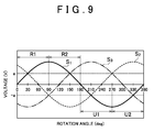
- the rotation angles ⁇ (n) corresponding to (1 / E 1 )sin -1 (S 1 (n) / A 1 ) are two rotation angles, that is, a rotation angle in a region U1 from 180° to 270° and a rotation angle in a region U2 from 270° to 360°.
- the second output signal S 2 (n) determines which of the two rotation angles computed according to the expression (35) is the actual rotation angle on the basis of the second output signal S 2 (n). Specifically, in the case where the first output signal S 1 (n) takes a positive value, if the second output signal S 2 (n) is equal to or greater than the threshold -a, it is determined that the rotation angle in the region R1 among the two rotation angles computed according to the expression (35) is the actual rotation angle. On the other hand, if the second output signal S 2 (n) is smaller than the threshold -a, it is determined that the rotation angle in the region R2 among the two rotation angles computed according to the expression (35) is the actual rotation angle.
- the second output signal S 2 (n) is smaller than the threshold a, it is determined that the rotation angle in the region U1 among the two rotation angles computed according to the expression (35) is the actual rotation angle.
- the second output signal S 2 (n) is equal to or greater than the threshold a, it is determined that the rotation angle in the region U2 among the two rotation angles computed according to the expression (35) is the actual rotation angle.
- the fourth computation mode is a computation mode that is applied in the case where neither the first computation mode nor the second computation mode can be applied and the angular width error correction value E 2 corresponding to a magnetic pole sensed by the second magnetic sensor 72 and the amplitude A 2 of the second output signal S 2 have already been computed in the first computation mode or the third computation mode and stored in the memory.
- the rotation angle ⁇ is computed mainly based on the output signal S 2 from the second magnetic sensor 72.
- the second output signal S 2 (n) takes a positive value
- the first output signal S 1 (n) is smaller than the threshold -a
- it is determined that the rotation angle within the range of 240° to 330° among the two rotation angles computed according to the expression (37) is the actual rotation angle.
- the first output signal S 1 (n) is equal to or greater than the threshold -a, it is determined that the rotation angle within the range of 0° to 60° or the range of 330° to 360° among the two rotation angles computed according to the expression (37) is the actual rotation angle.
- the second output signal S 2 (n) takes a negative value
- the first output signal S 1 (n) is equal to or greater than the threshold a
- the first output signal S 1 (n) is smaller than the threshold a, it is determined that the rotation angle within the range of 150° to 240° among the two rotation angles computed according to the expression (37) is the actual rotation angle.
- the fifth computation mode is applied when the magnetic pole sensed by the second magnetic sensor 72 is changed from the one in the state where the same magnetic pole (M2 in this example) is sensed by the second and third magnetic sensors 72, 73, in the case where the magnet 61 (the input shaft 8) is rotating in the direction indicated by an arrow, for example, as illustrated in FIG. 8C .
- E 3 is the angular width error correction value corresponding to the magnetic pole sensed by the third magnetic sensor 73.
- the rotation angle ⁇ (n) is expressed by the following expression (39) based on the expression (38).
- ⁇ n 1 / E 3 sin - 1 S 3 n / A 3 - 240
- FIG. 10 is a flowchart showing the operation of the first rotation angle computation unit 77A.
- the first rotation angle computation unit 77A executes a rotation angle computing process based on forced rotation (step S1).
- the electric motor 18 is forced to rotate temporarily to rotate the input shaft 8 (the output shaft 9), and the rotation angle ⁇ of the input shaft 8 is computed. Details of the process will be described later.
- the immediately preceding computed values of E ⁇ (n) (or E ⁇ (n)), E, and ⁇ (n) are used as the present values of E ⁇ (n) (or E ⁇ (n)), E, and ⁇ (n) (see the second arithmetic expression from the top of Table 1).
- the power supply for the torque computation ECU 77 is turned on by turning on the ignition key, there are no immediately preceding computed values of E ⁇ (n) (or E ⁇ (n)), E, and ⁇ (n).
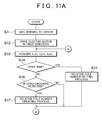
- FIG. 11A , FIG. 11B , and FIG. 11C are flowcharts showing the procedure of the rotation angle computing process based on forced rotation in step S1 in FIG. 10 .
- the numbers assigned to the magnetic poles, as relative numbers, using the magnetic pole sensed by the first magnetic sensor 71 at the start of the rotation angle computing process based on forced rotation as a reference magnetic pole are defined as relative pole numbers.
- first relative pole number The relative pole number of a magnetic pole sensed by the first magnetic sensor 71 (hereinafter, referred to as "first relative pole number”) is expressed by a variable r1
- second relative pole number the relative pole number of a magnetic pole sensed by the second magnetic sensor 72
- third relative pole number the relative pole number of a magnetic pole sensed by the third magnetic sensor 73
- r1, r2, r3 takes an integer from one to eight, the relative pole number that is smaller than one by one is eight, and the relative pole number that is greater than eight by one is one.
- the memory of the torque computation ECU 77 there are provided, for example, areas denoted by e1 to e7.
- the angular width error correction values E are stored in association with the relative magnetic pole numbers 1 to 8.
- the amplitudes A 1 of the first output signal S 1 are stored in association with the relative magnetic pole numbers 1 to 8.
- the amplitudes A 2 of the second output signal S 2 are stored in association with the relative magnetic pole numbers 1 to 8.
- the amplitudes A 3 of the third output signal S 3 are stored in association with the relative magnetic pole numbers 1 to 8.
- the first rotation angle computation unit 77A drives the electric motor 18 to rotate the electric motor 18 in a first direction (step S12). Specifically, the first rotation angle computation unit 77A transmits, to the motor control ECU 12, a first forced rotation command according to which the electric motor 18 is driven to be rotated in the first direction. Upon reception of the first forced rotation command, the motor control ECU 12 drives the electric motor 18 to rotate the electric motor 18 in the first direction.
- the first rotation angle computation unit 77A determines whether the present process is first process after the start of the rotation angle computing process based on forced rotation (step S14). If the present process is the first process after the start of the rotation angle computing process based on forced rotation (YES in step S14), the first rotation angle computation unit 77A executes a relative pole number setting process (step S15).
- step S53 the first rotation angle computation unit 77A determines that the rotation angle of the input shaft 8 is 180°, and sets the first relative pole number r1 to two (step S55). Then, the first rotation angle computation unit 77A proceeds on to step S56. In step S56, the first rotation angle computation unit 77A determines whether the condition that "S 1 ⁇ 0 and S 2 > 0" or the condition that "S 1 ⁇ 0 and S 2 ⁇ 0" is satisfied.
- FIG. 14A, FIG. 14B, and FIG. 14C schematically illustrate signal waveforms of the first, second and third output signals S 1 , S 2 , S 3 at the time when a magnetic pole pair constituted of, for example, the magnetic pole M1 and the magnetic pole M2 in the magnet 61 passes by the first magnetic sensor 71.
- the pole number of the magnetic pole sensed by the second magnetic sensor 72 is the same as the pole number of the magnetic pole sensed by the first magnetic sensor 71.
- the pole number of the magnetic pole sensed by the second magnetic sensor 72 is greater by one than the pole number of the magnetic pole sensed by the first magnetic sensor 71.
- both the sensor values S 1 , S 2 satisfy the first condition that S 1 ⁇ 0 and S 2 > 0.
- both the sensor values S 1 , S 2 satisfy the second condition that S 1 > 0 and S 2 ⁇ 0.
- both the sensor values S 1 , S 2 satisfy the third condition that S 1 ⁇ 0 and S 2 ⁇ 0.
- both the sensor values S 1 , S 2 satisfy the fourth condition that S 1 ⁇ 0 and S 2 ⁇ 0.
- the first rotation angle computation unit 77A executes a relative pole number updating process (step S17). Specifically, the first rotation angle computation unit 77A changes the relative pole number r1, r2 or r3, which is presently set for the magnetic sensor that outputs the sensor value zero-crossing of which is detected in step S16, to a number that is greater by one or a number that is smaller by one than the presently set relative pole number r1, r2 or r3 on the basis of the rotation direction of the input shaft 8 (the magnet 61).
- the first rotation angle computation unit 77A updates the relative pole number r1, r2, or r3 presently set for the magnetic sensor that outputs the sensor value zero-crossing of which is detected in step S 16, to a number that is smaller by one than the presently set relative pole number r1, r2 or r3.
- the relative pole number that is smaller than the relative pole number "one" by one is “eight”.
- the relative pole number that is greater than the relative pole number "eight" by one is "one".
- the rotation direction of the input shaft 8 can be determined on the basis of, for example, the immediately preceding value and the present value of the output signal zero-crossing of which is detected and the present value of the other output signal. Specifically, when the output signal zero-crossing of which is detected is the first output signal S 1 , if the condition that "the immediately preceding value of the first output signal S 1 is greater than zero, the present value of the first output signal S 1 is equal to or smaller than zero, and the second output signal S 2 is smaller than zero" or the condition that "the immediately preceding value of the first output signal S 1 is smaller than zero, the present value of the first output signal S 1 is equal to or greater than zero, and the second output signal S 2 is greater than zero" is satisfied, it is determined that the rotation direction is the forward direction (the direction indicated by the arrow in FIG. 6 ).
- the rotation direction is the forward direction (the direction indicated by the arrow in FIG. 6 ).
- the first rotation angle computation unit 77A proceeds on to step S18 in FIG. 11B .
- step S18 the first rotation angle computation unit 77A determines whether the condition that the first and second magnetic sensors 71, 72 sense one and the same magnetic pole for three consecutive computation periods is satisfied. If the condition in step S18 is not satisfied (NO in step S18), the first rotation angle computation unit 77A determines whether the condition that the second and third magnetic sensors 72, 73 sense one and the same magnetic pole for three consecutive computation periods is satisfied (step S20). If the condition in step S20 is not satisfied (NO in step S20), the first rotation angle computation unit 77A returns to step S 13 in FIG. 11A .
- step S20 If it is determined in step S20 that the condition in step S20 is satisfied (YES in step S20), the first rotation angle computation unit 77A determines whether the condition that none of the denominators of the fractions included in the arithmetic expressions used to compute E ⁇ and E are zero is satisfied (step S21). If the condition in step S21 is not satisfied (NO in step S21), the first rotation angle computation unit 77A returns to step S13 in FIG. 11A . On the other hand, if the condition in step S21 is satisfied (YES in step S21), the first rotation angle computation unit 77A proceeds on to step S22.
- step S22 the first rotation angle computation unit 77A drives the electric motor 18 to rotate the electric motor 18 in a second direction that is the opposite direction of the first direction. Specifically, the first rotation angle computation unit 77A transmits, to the motor control ECU 12, a second forced rotation command according to which the electric motor 18 is driven to be rotated in the second direction. Upon reception of the second forced rotation command, the motor control ECU 12 drives the electric motor 18 to rotate the electric motor 18 in the second direction.
- the first rotation angle computation unit 77A obtains the sensor values S 1 (n), S 2 (n), S 3 (n) from the respective magnetic sensors, 71, 72, 73 (step S23). The process in step S23 is repeatedly executed with a predetermined computation period until an affirmative determination is made in step S27 or step S31 described later. Then, the first rotation angle computation unit 77A determines whether zero-crossing of each of the sensor values S 1 , S 2 , S 3 , that is, inversion of the sign of each of the sensor values S 1 , S 2 , S 3 is detected, on the basis of the sensor values S 1 , S 2 , S 3 stored in the memory (step S24). If zero-crossing is not detected (NO in step S24), the first rotation angle computation unit 77A proceeds on to step S26 in FIG. 11C .
- step S25 If zero-crossing of one of the sensor values S 1 , S 2 , S 3 is detected in step S24 (YES in step S24), the first rotation angle computation unit 77A executes a relative pole number updating process (step S25).
- the relative pole number updating process is the same as the relative pole number updating process in step S17 described above.
- the first rotation angle computation unit 77A proceeds on to step S26 in FIG. 11C .
- step S26 the first rotation angle computation unit 77A determines whether the condition that both the first and second magnetic sensors 71, 72 sense one and the same magnetic pole for three consecutive computation periods is satisfied. If the condition in step S26 is not satisfied (NO in step S26), the first rotation angle computation unit 77A determines whether the condition that both the second and third magnetic sensors 72, 73 sense one and the same magnetic pole for three consecutive computation periods is satisfied (step S30). If the condition in step S30 is not satisfied (NO in step S30), the first rotation angle computation unit 77A returns to step S23 in FIG. 11B .
- step S26 If it is determined in step S26 that the condition in step S26 is satisfied (YES in step S26), the first rotation angle computation unit 77A determines whether the condition that none of the denominators of the fractions included in the E ⁇ basic arithmetic expression and the E arithmetic expression for the first computation mode are zero is satisfied (step S27). If the condition in step S27 is not satisfied (NO in step S27), the first rotation angle computation unit 77A returns to step S23 in FIG. 11B .
- step S27 If it is determined that the condition in step S27 is satisfied (YES in step S27), the first rotation angle computation unit 77A computes the values of ⁇ (n), E, A 1 , and A 2 in the first computation mode (step S28). Then, the first rotation angle computation unit 77A stores the computed values of E, A 1 , and A 2 in the memory in association with the relative pole number of the magnetic pole sensed by the first and second magnetic sensors 71, 72 (step S29).
- the relative pole number of the magnetic pole sensed by the first and second magnetic sensors 71, 72 is the same number as the presently set first relative pole number r1 or second relative pole number r2.
- step S30 If it is determined in step S30 that the condition in step S30 is satisfied (YES in step S30), the first rotation angle computation unit 77A determines whether the condition that none of the denominators of the fractions included in the E ⁇ basic arithmetic expression and the E arithmetic expression for the second computation mode are zero is satisfied (step S31). If the condition in step S31 is not satisfied (NO in step S31), the first rotation angle computation unit 77A returns to step S23 in FIG. 11B .
- step S31 If it is determined that the condition in step S31 is satisfied (YES in step S31), the first rotation angle computation unit 77A computes the values of ⁇ (n), E, A 2 , and A 3 in the second computation mode (step S32). Then, the first rotation angle computation unit 77A stores the computed values of E, A 2 , and A 3 in the memory in association with the relative pole number of the magnetic pole sensed by the second and third magnetic sensors 72, 73 (step S33).
- the relative pole number of the magnetic pole sensed by the second and third magnetic sensors 72, 73 is the same number as the presently set second relative pole number r2 or third relative pole number r3.
- step S34 the first rotation angle computation unit 77A stops driving of the electric motor 18 and cancels the warning for the driver. Specifically, the first rotation angle computation unit 77A transmits a driving stop command for the electric motor 18 to the motor control ECU 12, and also transmits a warning cancellation command to the image-voice control unit. Upon reception of the driving stop command for the electric motor 18, the motor control ECU 12 stops driving of the electric motor 18. Upon reception of the warning cancellation command, the image-voice control unit cancels the warning display, the warning voice output, or the like. Thus, the rotation angle computing process based on forced rotation ends.
- the first rotation angle computation unit 77A determines whether zero-crossing of each of the sensor values S 1 , S 2 , S 3 , that is, inversion of the sign of each of the sensor values S 1 , S 2 , S 3 is detected, on the basis of the sensor values S 1 , S 2 , S 3 stored in the memory (step S62). If zero-crossing is not detected (NO in step S62), the first rotation angle computation unit 77A proceeds on to step S64.
- step S64 the first rotation angle computation unit 77A determines whether the condition that both the first and second magnetic sensors 71, 72 sense one and the same magnetic pole for three consecutive computation periods is satisfied. If the condition in step S64 is satisfied (YES in step S64), the first rotation angle computation unit 77A computes the values of ⁇ (n), E, A 1 , and A 2 in the first computation mode (step S65).
- the first rotation angle computation unit 77A determines whether the condition that none of the denominators of the fractions included in the E ⁇ basic arithmetic expression and the E arithmetic expression are zero is satisfied (step S66). If the condition in step S66 is satisfied (YES in step S66), the first rotation angle computation unit 77A stores the computed values of E, A 1 , and A 2 in the memory in association with the relative pole number of the magnetic pole sensed by the first and second magnetic sensors 71, 72 (step S67).
- the relative pole number of the magnetic pole sensed by the first and second magnetic sensors 71, 72 is the same number as the presently set first relative pole number r1 or second relative pole number r2.
- the first rotation angle computation unit 77A stores the computed values of E, A 1 , and A 2 in the storage locations in the areas e1, e2, e3 of the memory, which are associated with the presently set first relative pole number r1. Note that, if the values of E, A 1 , and A 2 have already been stored in the above-described storage locations in the areas e1, e2, e3 of the memory, the already stored values of E, A 1 , and A 2 are overwritten with the presently computed values of E, A 1 , and A 2 . Then, the first rotation angle computation unit 77A ends the process in the present computation period.
- step S66 If it is determined in step S66 that the condition in step S66 is not satisfied (NO in step S66), the first rotation angle computation unit 77A ends the process in the present computation period without executing the process in step S67. Therefore, in this case, the values of E, A 1 , and A 2 computed in step S65 are not stored in the areas e1, e2, e3 of the memory.
- the first rotation angle computation unit 77A determines whether the denominators of the fractions included in the E ⁇ basic arithmetic expression are not zero and whether the denominators of the fractions included in the E arithmetic expression are not zero, and computes the values of ⁇ (n), E, A 2 , and A 3 on the basis of the results of determinations.
- the first rotation angle computation unit 77A determines whether the condition that none of the denominators of the fractions included in the E ⁇ basic arithmetic expression and the E arithmetic expression are zero is satisfied (step S70). If the condition in step S70 is satisfied (YES in step S70), the first rotation angle computation unit 77A stores the computed values of E, A 2 , and A 3 in the memory in association with the relative pole number of the magnetic pole sensed by the second and third magnetic sensors 72, 73 (step S71).
- step S70 If it is determined in step S70 that the condition in step S70 is not satisfied (NO in step S70), the first rotation angle computation unit 77A ends the process in the present computation period without executing the process in step S71. Therefore, in this case, the values of E, A 2 , and A 3 computed in step S69 are not stored in the areas e1, e3, e4 of the memory.
- step S68 If it is determined in step S68 that the condition in step S68 is not satisfied (NO in step S68), it is determined whether the magnetic pole width error correction value E corresponding to the magnetic pole sensed by the first magnetic sensor 71 is stored in the memory (step S72). This determination is made based on whether the magnetic pole width error correction value E is stored in a storage location in the area e1 of the memory, which is associated with the presently set first relative pole number r1.
- step S72 If the magnetic pole width error correction value E corresponding to the magnetic pole sensed by the first magnetic sensor 71 is stored in the memory (YES in step S72), the first rotation angle computation unit 77A computes the rotation angle ⁇ (n) in the third computation mode (step S73). Then, the first rotation angle computation unit 77A ends the process in the present computation period. If it is determined in step S72 that the magnetic pole width error correction value E corresponding to the magnetic pole sensed by the first magnetic sensor 71 is not stored in the memory (NO in step S72), the first rotation angle computation unit 77A proceeds on to step S74.
- step S74A the first rotation angle computation unit 77A determines whether the magnetic pole width error correction value E corresponding to the magnetic pole sensed by the second magnetic sensor 72 is stored in the memory. This determination is made based on whether the magnetic pole width error correction value E is stored in a storage location in the area e2 of the memory, which is associated with the presently set second relative pole number r2.
- step S66 in FIG. 15B may be omitted and step S67 may be executed after completion of the process in step S65.
- step S70 in FIG. 15B may be omitted and step S71 may be executed after completion of the process in step S69.
Landscapes
- Physics & Mathematics (AREA)
- General Physics & Mathematics (AREA)
- Power Steering Mechanism (AREA)
- Measurement Of Length, Angles, Or The Like Using Electric Or Magnetic Means (AREA)
- Transmission And Conversion Of Sensor Element Output (AREA)
Abstract
Description
- The invention relates to a rotation angle detection device that detects a rotation angle of a rotary body.
- As a rotation angle detection device that detects a rotation angle of a rotary body, there has been known a rotation angle detection device that detects a rotation angle of a rotor of a brushless motor with the use of a detection rotor that rotates in accordance with the rotation of the brushless motor. Specifically, as illustrated in
FIG. 16 , a detection rotor 201 (hereinafter, referred to as "rotor 201") includes acylindrical magnet 202 having a plurality of magnetic pole pairs corresponding to magnetic pole pairs formed in a rotor of a brushless motor. Two magnetic sensors 221, 222 are arranged around therotor 201 at a predetermined angular interval around the rotation central axis of therotor 201. The magnetic sensors 221, 222 respectively output sinusoidal signals having a predetermined phase difference. On the basis of the two sinusoidal signals, a rotation angle of the rotor 201 (a rotation angle of the brushless motor) is detected. - In this example, the
magnet 202 has five magnetic pole pairs. That is, themagnet 202 has ten magnetic poles arranged at equal angular intervals. The magnetic poles are arranged at angular intervals of 36° (180° in electrical angle) around the rotation central axis of therotor 201. Further, the two magnetic sensors 221, 222 are arranged at an angular interval of 18° (90° in electrical angle) around the rotation central axis of therotor 201. - The direction indicated by an arrow in
FIG. 16 is defined as the forward rotation direction of thedetection rotor 201. The rotation angle of therotor 201 increases as therotor 201 is rotated in the forward direction, whereas the rotation angle of therotor 201 decreases as therotor 201 is rotated in the reverse direction. The magnetic sensors 221, 222 output sinusoidal signals S1, S2, respectively. As illustrated inFIG. 17 , one period of each of the sinusoidal signals S1, S2 corresponds to a duration in which therotor 201 rotates an angle of 72° (360° in electrical angle) corresponding to one magnetic pole pair. - The angular range corresponding to one rotation of the
rotor 201 is divided into five sections corresponding to the five magnetic pole pairs, a start position of each section is defined as 0°, and an end position of each section is defined as 360°. A rotation angle of therotor 201 expressed under the above-described conditions is an electrical angle θ of therotor 201. In this case, the first magnetic sensor 221 outputs an output signal of S1 = A1 · sinθ, and the second magnetic sensor 222 outputs an output signal of S2 = A2 · cosθ. Each of A1 and A2 represents an amplitude. If the amplitude A1 of the output signal S1 and the amplitude A2 of the output signal S2 are assumed to be equal to each other, the electrical angle θ of therotor 201 is obtained with the use of both the output signals S1, S2 based on the following expression.
- The thus obtained electrical angle θ is used to control the brushless motor. Refer to, for example, Japanese Patent Application Publication No.
2008-26297 JP 2008-26297 A - In the above-described conventional rotation angle detection device, the rotation angle θ is computed on the assumption that the amplitudes A1, A2 of the output signals S1, S2 output from the magnetic sensors 221, 222 are equal to each other. However, the amplitudes A1, A2 of the output signals S1, S2 vary depending on variations of the temperature characteristics of the magnetic sensors 221, 222 and temperature changes. Therefore, an error may be caused in detection of a rotation angle of the rotor due to variations of the temperature characteristics of the magnetic sensors 221, 222 and temperature changes.
- One object of the invention is to provide a rotation angle detection device that is able to detect a rotation angle with a high degree of accuracy.
- A rotation angle detection device according to an aspect of the invention includes: a multipolar magnet that rotates in accordance with rotation of a rotary body, and that has a plurality of magnetic poles; three magnetic sensors that respectively output sinusoidal signals having a predetermined phase difference in accordance with rotation of the multipolar magnet; a sampling unit that samples an output signal from each of the magnetic sensors at prescribed timings; a first computation unit that computes a rotation angle of the rotary body based on the output signals from two magnetic sensors among the three magnetic sensors, the output signals being sampled at three sampling timings, when a condition that both the two magnetic sensors among the three magnetic sensors sense one and the same magnetic pole for three consecutive sampling periods is satisfied, and computes information regarding a magnetic pole width of the magnetic pole sensed by the two magnetic sensors and information regarding amplitudes of the output signals from the two magnetic sensors and stores the information regarding the magnetic pole width and the information regarding the amplitudes in association with the magnetic pole sensed by the two magnetic sensors, at all times or when the output signals sampled at the three sampling timings satisfy a prescribed requirement; and a second computation unit that computes the rotation angle of the rotary body based on the information stored by the first computation unit and the output signals from two magnetic sensors among the three magnetic sensors, the two magnetic sensors including one of the three magnetic sensors, which senses the magnetic pole associated with the stored information regarding the magnetic pole width, when the condition is not satisfied.
- According to the above-described aspect, the rotation angle of the rotary body is computed based on the output signals from two magnetic sensors among the three magnetic sensors, the output signals being sampled at three sampling timings, when the condition that both the two magnetic sensors among the three magnetic sensors sense one and the same magnetic pole for three consecutive sampling periods is satisfied. Therefore, it is possible to compute the rotation angle with a high degree of accuracy. On the other hand, when the above-described condition is not satisfied, the rotation angle of the rotary body is computed based on the information stored by the first computation unit and the output signals from two magnetic sensors among the three magnetic sensors, the two magnetic sensors including one of the three magnetic sensors, which senses the magnetic pole associated with the stored information regarding the magnetic pole width. Therefore, it is possible to compute the rotation angle at an accuracy close to the accuracy achieved by the first computation unit.
- In the rotation angle detection device according to the above-described aspect, in a case where the three magnetic sensors are a first magnetic sensor, a second magnetic sensor, and a third magnetic sensor, a phase difference between an output signal from the first magnetic sensor and an output signal from the second magnetic sensor may be 120°, and a phase difference between the output signal from the first magnetic sensor and an output signal from the third magnetic sensor may be 240°.
- With this configuration, when two magnetic sensors constituted of the combination of the first magnetic sensor and the second magnetic sensor sense different magnetic poles, two magnetic sensors constituted of the combination of the second magnetic sensor and the third magnetic sensor sense one and the same magnetic pole. On the other hand, when two magnetic sensors constituted of the combination of the second magnetic sensor and the third magnetic sensor sense different magnetic poles, two magnetic sensors constituted of the combination of the first magnetic sensor and the second magnetic sensor sense one and the same magnetic pole. Therefore, the probability that the condition that two magnetic sensors among the three magnetic sensors sense one and the same magnetic pole for three consecutive sampling periods is satisfied becomes higher. Thus, the probability that the rotation angle is computed by the first computation unit that can compute the rotation angle with a high degree of accuracy becomes higher.
- In the rotation angle detection device according to the above-described aspect: the information regarding the magnetic pole width of the magnetic pole may be a magnetic pole width error correction value used to correct a rotation angle error based on a magnetic pole width error of the magnetic pole; an output signal S1 from the first magnetic sensor may be expressed by S1 = A1sin(E1θ) where A1 is an amplitude of the output signal from the first magnetic sensor, E1 is a magnetic pole width error correction value corresponding to a magnetic pole sensed by the first magnetic sensor, and θ is the rotation angle of the rotary body; an output signal S2 from the second magnetic sensor may be expressed by S2 = A2sin(E2θ + 120) where A2 is an amplitude of the output signal from the second magnetic sensor and E2 is a magnetic pole width error correction value corresponding to a magnetic pole sensed by the second magnetic sensor; and an output signal S3 from the third magnetic sensor may be expressed by S3 = A3sin(E3θ + 240) where A3 is an amplitude of the output signal from the third magnetic sensor and E3 is a magnetic pole width error correction value corresponding to a magnetic pole sensed by the third magnetic sensor.
- The foregoing and further features and advantages of the invention will become apparent from the following description of example embodiments with reference to the accompanying drawings, wherein like numerals are used to represent like elements and wherein:
-
FIG. 1 is a schematic view illustrating the schematic configuration of an electric power steering system to which a rotation angle detection device according to an embodiment of the invention is applied; -
FIG. 2 is a schematic diagram illustrating the electrical configuration of a motor control ECU; -
FIG. 3 is a schematic diagram schematically illustrating the configuration of an electric motor; -
FIG. 4 is a graph illustrating an example of a manner of setting a q-axis current command value Iq* with respect to a detected steering torque Th; -
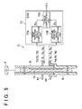
FIG. 5 is a schematic view schematically illustrating the configuration of a torque sensor; -
FIG. 6 is a schematic diagram illustrating the configuration of a first magnet and the arrangement of three magnetic sensors; -
FIG. 7 is a schematic diagram illustrating waveforms of output signals from a first magnetic sensor, a second magnetic sensor and a third magnetic sensor; -
FIG. 8A is a schematic view illustrating the case where a third computation mode is applied; -
FIG. 8B is a schematic view illustrating the case where a fourth computation mode is applied; -
FIG. 8C is a schematic view illustrating the case where a fifth computation mode is applied; -
FIG. 9 is a graph illustrating the third computation mode; -
FIG. 10 is a flowchart showing the operation of a first rotation angle computation unit; -
FIG. 11A is a flowchart showing part of the procedure of a rotation angle computing process based on forced rotation in step S1 inFIG. 10 ; -
FIG. 11B is a flowchart showing part of the procedure of the rotation angle computing process based on forced rotation in step S1 inFIG. 10 ; -
FIG. 11C is a flowchart showing part of the procedure of the rotation angle computing process based on forced rotation in step S1 inFIG. 10 ; -
FIG. 12 is a schematic diagram showing part of the contents of a memory in a torque computation ECU; -
FIG. 13 is a flowchart showing the detailed procedure of a relative pole number setting process; -
FIG. 14A is a schematic diagram illustrating the relative pole number setting process; -
FIG. 14B is a schematic diagram illustrating the relative pole number setting process; -
FIG. 14C is a schematic diagram illustrating the relative pole number setting process; -
FIG. 15A is a flowchart showing part of the procedure of a normal rotation angle computing process in step S2 inFIG. 10 ; -
FIG. 15B is a flowchart showing part of the procedure of the normal rotation angle computing process in step S2 inFIG. 10 ; -
FIG. 15C is a flowchart showing part of the procedure of the normal rotation angle computing process in step S2 inFIG. 10 ; -
FIG. 16 is a schematic diagram illustrating a rotation angle detection method executed by a conventional rotation angle detection device; and -
FIG. 17 is a schematic diagram illustrating waveforms of output signals from a first magnetic sensor and a second magnetic sensor. - Hereinafter, embodiments of the invention will be described with reference to the accompanying drawings. As illustrated in
FIG. 1 , an electricpower steering system 1 includes asteering wheel 2, which serves as a steering member used to steer a vehicle, a steeredmechanism 4 that steers steeredwheels 3 in accordance with the rotation of thesteering wheel 2, and asteering assist mechanism 5 used to assist a driver in performing a steering operation. Thesteering wheel 2 and the steeredmechanism 4 are mechanically connected to each other via asteering shaft 6 and anintermediate shaft 7. - The steering
shaft 6 includes aninput shaft 8 connected to thesteering wheel 2 and anoutput shaft 9 connected to theintermediate shaft 7. Theinput shaft 8 and theoutput shaft 9 are connected to each other via atorsion bar 10 so as to be rotatable relative to each other on the same axis. That is, when thesteering wheel 2 is rotated, theinput shaft 8 and theoutput shaft 9 rotate in the same direction while rotating relative to each other. - A torque sensor (torque detection device) 11, to which a rotation angle detection device according to an embodiment of the invention is applied, is arranged around the
steering shaft 6. Thetorque sensor 11 detects a steering torque applied to thesteering wheel 2 on the basis of a relative rotational displacement between theinput shaft 8 and theoutput shaft 9. The steering torque detected by thetorque sensor 11 is input into anelectronic control unit 12 for motor control (hereinafter, referred to as "motor control ECU 12"). - The steered
mechanism 4 is formed of a rack-and-pinion mechanism including apinion shaft 13 and arack shaft 14 that serves as a steered shaft. The steeredwheels 3 are connected to respective end portions of therack shaft 14 viatie rods 15 and knuckle arms (not illustrated). Thepinion shaft 13 is connected to theintermediate shaft 7. Thepinion shaft 13 rotates in accordance with steering of thesteering wheel 2. Apinion 16 is connected to a distal end of thepinion shaft 13. - The
rack shaft 14 linearly extends along the lateral direction of the vehicle (the direction orthogonal to the direction in which the vehicle travels straight ahead). Arack 17 that meshes with thepinion 16 is formed at an axially intermediate portion of therack shaft 14. Thepinion 16 and therack 17 convert the rotation of thepinion shaft 13 into an axial movement of therack shaft 14. By moving therack shaft 14 in the axial direction, the steeredwheels 3 are steered. - When the
steering wheel 2 is steered (rotated), the rotation is transmitted to thepinion shaft 13 via thesteering shaft 6 and theintermediate shaft 7. The rotation of thepinion shaft 13 is converted into an axial movement of therack shaft 14 by thepinion 16 and therack 17. As a result, the steeredwheels 3 are steered. Thesteering assist mechanism 5 includes anelectric motor 18 that generates steering assist force and a speed-reduction mechanism 19 that transmits torque output from theelectric motor 18 to the steeredmechanism 4. Theelectric motor 18 is formed of a three-phase brushless motor in the present embodiment. The speed-reduction mechanism 19 is formed of a worm gear mechanism including aworm shaft 20 and aworm wheel 21 that meshes with theworm shaft 20. The speed-reduction mechanism 19 is housed in agear housing 22 that serves as a transmission mechanism housing. - The
worm shaft 20 is driven to be rotated by theelectric motor 18. Theworm wheel 21 is connected to thesteering shaft 6 so as to be rotatable in the same direction as the rotation direction of thesteering shaft 6. Theworm wheel 21 is driven to be rotated by theworm shaft 20. When theworm shaft 20 is driven to be rotated by theelectric motor 18, theworm wheel 21 is driven to be rotated, and thesteering shaft 6 rotates. The rotation of thesteering shaft 6 is transmitted to thepinion shaft 13 via theintermediate shaft 7. The rotation of thepinion shaft 13 is converted into an axial movement of therack shaft 14. As a result, the steeredwheels 3 are steered. That is, when theworm shaft 20 is driven to be rotated by theelectric motor 18, the steeredwheels 3 are steered. - A rotation angle of a rotor of the electric motor 18 (a rotor rotation angle) is detected by a
rotation angle sensor 25 such as a resolver. A signal output from therotation angle sensor 25 is input into themotor control ECU 12. Theelectric motor 18 is controlled by themotor control ECU 12 that serves as a motor control unit.FIG. 2 is a schematic diagram illustrating the electrical configuration of themotor control ECU 12. - The
motor control ECU 12 realizes appropriate steering assistance suited to a steering state, by driving theelectric motor 18 on the basis of a steering torque Th detected by thetorque sensor 11. Themotor control ECU 12 includes amicrocomputer 40, a drive circuit (inverter circuit) 31 that is controlled by themicrocomputer 40 and that supplies electric power to theelectric motor 18, and acurrent detection unit 32 that detects a motor current passing through theelectric motor 18. - The
electric motor 18 is, for example, a three-phase brushless motor, and includes arotor 100, which serves as a field magnet, and astator 105 provided with U-phase, V-phase, and W-phase stator coils 101, 102, 103, as schematically illustrated inFIG. 3 . Theelectric motor 18 may be an electric motor of an inner rotor type, in which a stator is arranged outside a rotor so as to face the rotor, or may be an electric motor of an outer rotor type, in which a stator is arranged inside a tubular rotor so as to face the rotor. - A UVW coordinate system that is a three-phase fixed coordinate system is defined, in which a U-axis, a V-axis, and a W-axis are set to the respective directions of the
U-phase stator coil 101, the V-phase stator coil 102 and the W-phase stator coil 13. A dq coordinate system (an actual rotating coordinate system) that is a two-phase rotating coordinate system is defined, in which a d-axis that is a magnetic pole axis is set to the magnetic pole direction of therotor 100 and a q-axis that is a torque axis is set to the direction orthogonal to the d-axis within a rotary plane of therotor 100. The dq coordinate system is a rotating coordinate system that rotates together with therotor 100. In the dq coordinate system, because only a q-axis current contributes to generation of torque of therotor 100, a d-axis current is set to zero and the q-axis current is controlled on the basis of a desired torque. A rotation angle (electrical angle) θ-S of therotor 100 is a rotation angle of the d-axis with respect to the U-axis. The dq coordinate system is an actual rotating coordinate system that rotates in accordance with the rotor angle θ-S. With the use of the rotor angle θ-S, coordinate conversion between the UVW coordinate system and the dq coordinate system can be executed. - The
microcomputer 40 includes a CPU and memories (a ROM, a RAM, a non-volatile memory, etc.), and is configured to function as a plurality of functional processing units by executing predetermined programs. The functional processing units include a current commandvalue setting unit 41, a currentdeviation computation unit 42, a PI (Proportional Integral)control unit 43, a dq/UVW conversion unit 44, a PWM (Pulse Width Modulation)control unit 45, a UVW/dq conversion unit 46, and a rotationangle computation unit 47. - The rotation
angle computation unit 47 computes a rotor rotation angle (electrical angle) (hereinafter, referred to as "rotor angle θs") of theelectric motor 18 on the basis of a signal output from therotation angle sensor 25. The current commandvalue setting unit 41 sets current values, which are values of currents that should be passed through coordinate axes of the dq coordinate system, as current command values. Specifically, the current commandvalue setting unit 41 sets a d-axis current command value Id* and a q-axis current command value Iq* (hereinafter, the d-axis current command value Id* and the q-axis current command value Iq* will be collectively referred to as "two-phase current command values Idq*" where appropriate). More specifically, the current commandvalue setting unit 41 sets the q-axis current command value Iq* to a significant value, whereas it sets the d-axis current command value Id* to zero. More specifically, the current commandvalue setting unit 41 sets the q-axis current command value Iq* on the basis of the detected steering torque Th detected by thetorque sensor 11. - An example of a manner of setting the q-axis current command value Iq* with respect to the detected steering torque Th is shown in
FIG. 4 . With regard to the detected steering torque Th, for example, a torque for steering to the right takes a positive value, and a torque for steering to the left takes a negative value. The q-axis current command value Iq* takes a positive value when an operation assist force for steering to the right should be generated by theelectric motor 18, and takes a negative value when an operation assist force for steering to the left should be generated by theelectric motor 18. The q-axis current command value Iq* with respect to a positive value of the detected steering torque Th takes a positive value, and the q-axis current command value Iq* with respect to a negative value of the detected steering torque Th takes a negative value. When the detected steering torque Th is zero, the q-axis current command value Iq* is zero. The q-axis current command value Iq* is set such that the absolute value of the q-axis current command value Iq* increases as the absolute value of the detected steering torque Th increases. - The two-phase current command values Idq* set by the current command
value setting unit 41 are provided to the currentdeviation computation unit 42. Thecurrent detection unit 32 detects a U-phase current IU, a V-phase current IV, and a W-phase current IW for the electric motor 18 (hereinafter, the U-phase current IU, the V-phase current IV, and the W-phase current IW will be collectively referred to as "three-phase detected currents IUVW" where appropriate). The three-phase detected currents IUVW detected by thecurrent detection unit 32 are provided to the UVW/dq conversion unit 46. - The UVW/
dq conversion unit 46 executes coordinate conversion from the three-phase detected currents IUVW (the U-phase current IU, the V-phase current IV, and the W-phase current IW) of the UVW coordinate system detected by thecurrent detection unit 32, into two-phase detected currents Id, Iq of the dq coordinate system (hereinafter, the two-phase detected currents Id, Iq will be collectively referred to as "two-phase detected currents Idq" where appropriate). The rotor angle θs computed by the rotationangle computation unit 47 is used for this coordinate conversion. - The current
deviation computation unit 42 computes deviations between the two-phase current command values Idq* set by the current commandvalue setting unit 41 and the two-phase detected currents Idq provided from the UVW/dq conversion unit 46. Specifically, the currentdeviation computation unit 42 computes a deviation of the d-axis detected current Id with respect to the d-axis current command value Id* and a deviation of the q-axis detected current Iq with respect to the q-axis current command value Iq*. These deviations are provided to thePI control unit 43. - The
PI control unit 43 generates two-phase voltage command values Vdq* (the d-axis voltage command value Vd* and the q-axis voltage command value Vq*), which are values of voltages that should be applied to theelectric motor 18, by executing a PI computation on the current deviations computed by the currentdeviation computation unit 42. The two-phase voltage command values Vdq* are provided to the dq/UVW conversion unit 44. The dq/UVW conversion unit 44 executes coordinate conversion from the two-phase voltage command values Vdq* into three-phase voltage command values VUVW*. The rotor angle θs computed by the rotationangle computation unit 47 is used for this coordinate conversion. The three-phase voltage command values VUVW* consist of a U-phase voltage command value VU*, a V-phase voltage command value VV*, and a W-phase voltage command value VW*. The three-phase voltage command values VUVW* are provided to thePWM control unit 45. - The
PWM control unit 45 generates a U-phase PWM control signal, a V-phase PWM control signal, and a W-phase PWM control signal having duty ratios corresponding to the U-phase voltage command value VU*, the V-phase voltage command value VV*, and the W-phase voltage command value VW*, respectively, and provides these control signals to thedrive circuit 31. Thedrive circuit 31 is formed of an inverter circuit with three phases corresponding to the U-phase, the V-phase, and the W-phase. When power elements constituting the inverter circuit are controlled by the PWM control signals provided from thePWM control unit 45, voltages corresponding to the three-phase voltage command values VUVW* are applied to theU-phase stator coil 101, the V-phase stator coil 102 and the W-phase stator coil 103 of theelectric motor 18. - The current
deviation computation unit 42 and thePI control unit 43 constitute a current feedback controller. Due to the action of the current feedback controller, motor currents passing through theelectric motor 18 are controlled so as to approach the two-phase current command values Idq* set by the current commandvalue setting unit 41.FIG. 5 is a schematic view schematically showing the configuration of thetorque sensor 11. - An annular first magnet (a multipolar magnet) 61 is connected to the
input shaft 8 so as to be rotatable together with theinput shaft 8. Threemagnetic sensors first magnet 61 are arranged below thefirst magnet 61. An annular second magnet (a multipolar magnet) 62 is connected to theoutput shaft 9 so as to be rotatable together with theoutput shaft 9. Three magnetic sensors 74, 75, 76 that respectively output sinusoidal signals having a phase difference in accordance with the rotation of thesecond magnet 62 are arranged above thesecond magnet 62. - The output signals S1 to S6 from the respective
magnetic sensors 71 to 76 are input into atorque computation ECU 77 used to compute a steering torque that is applied to theinput shaft 8. A power supply for thetorque computation ECU 77 is turned on when an ignition key is turned on. When the ignition key is turned off, an ignition key off operation signal indicating that the ignition key is turned off is input into thetorque computation ECU 77. A magnetic sensor including an element having electrical characteristics that vary due to the action of a magnetic force, for example, a Hall element or a magnetoresistive element (a MR element) may be used as each of the magnetic sensors. In the present embodiment, a Hall element is used as each of the magnetic sensors. - The
magnets magnetic sensors 71 to 76, and thetorque computation ECU 77 constitute thetorque sensor 11. Thetorque computation ECU 77 includes a microcomputer. The microcomputer is provided with a CPU and memories (a ROM, a RAM, a nonvolatile memory, etc.), and functions as a plurality of functional processing units by executing predetermined programs. The functional processing units include a first rotationangle computation unit 77A, a second rotationangle computation unit 77B, and atorque computation unit 77C. - The first rotation
angle computation unit 77A computes the rotation angle (an electrical angle θA) of theinput shaft 8 on the basis of the output signals S1, S2, S3 from the threemagnetic sensors angle computation unit 77B computes the rotation angle (an electrical angle θB) of theoutput shaft 9 on the basis of the output signals S4, S5, S6 from the three magnetic sensors 74, 75, 76. Thetorque computation unit 77C computes the steering torque Th applied to theinput shaft 8 on the basis of the rotation angle θA of theinput shaft 8 detected by the first rotationangle computation unit 77A and the rotation angle θB of theoutput shaft 9 detected by the second rotationangle computation unit 77B. Specifically, the steering torque Th is computed according to the following expression (1) where K is a spring constant of thetorsion bar 10 and N is the number of magnetic pole pairs formed in each of themagnets 
- The
first magnet 61, themagnetic sensors angle computation unit 77A constitute a first rotation angle detection device used to detect the rotation angle θA of theinput shaft 8. Thesecond magnet 62, the magnetic sensors 74, 75, 76 and the second rotationangle computation unit 77B constitute a second rotation angle detection device used to detect the rotation angle θB of theoutput shaft 9. Because an operation of the first rotation angle detection device (the first rotationangle computation unit 77A) is the same as an operation of the second rotation angle detection device (the second rotationangle computation unit 77B), only the operation of the first rotation angle detection device (the firstrotation computation unit 77A) will be described below. -
FIG. 6 is a schematic diagram illustrating the configuration of thefirst magnet 61 and the arrangement of the threemagnetic sensors first magnet 61 has four magnetic pole pairs (M1, M2), (M3, M4), (M5, M6), (M7, M8) arranged at equal angular intervals in the circumferential direction. That is, thefirst magnet 61 has the eight magnetic poles M1 to M8 arranged at the equal angular intervals. The magnetic poles M1 to M8 are arranged at angular intervals (angular widths) of approximately 45° (approximately 180° in electrical angle) around the central axis of theinput shaft 8. The magnitudes of magnetic forces of the magnetic poles M1 to M8 are substantially equal to each other. - The three
magnetic sensors first magnet 61. In the following description, themagnetic sensor 71 will be referred to as a firstmagnetic sensor 71, themagnetic sensor 72 will be referred to as a secondmagnetic sensor 72, and themagnetic sensor 73 will be referred to as a thirdmagnetic sensor 73 where appropriate. The firstmagnetic sensor 71 and the secondmagnetic sensor 72 are arranged at an angular interval of 120° in electrical angle around the central axis of theinput shaft 8. The secondmagnetic sensor 72 and the thirdmagnetic sensor 73 are arranged at an angular interval of 120° in electrical angle around the central axis of theinput shaft 8. Therefore, the firstmagnetic sensor 71 and the thirdmagnetic sensor 73 are arranged at an angular interval of 240° in electrical angle around the central axis of theinput shaft 8. - The direction indicated by an arrow in
FIG. 6 is defined as the forward rotation direction of theinput shaft 8. The rotation angle of theinput shaft 8 increases as theinput shaft 8 is rotated in the forward direction, and the rotation angle of theinput shaft 8 decreases as theinput shaft 8 is rotated in the reverse direction. Sinusoidal signals S1, S2, S3 are respectively output from themagnetic sensors input shaft 8, as illustrated inFIG. 7 . Note that a rotation angle (deg) on the abscissa axis inFIG. 7 represents a mechanical angle. - In the following description, the output signal S1 from the first
magnetic sensor 71 will be referred to as a first output signal S1 or a first sensor value S1, the output signal S2 from the secondmagnetic sensor 72 will be referred to as a second output signal S2 or a second sensor value S2, and the output signal S3 from the thirdmagnetic sensor 73 will be referred to as a third output signal S3 or a third sensor value S3, where appropriate. In the following description, a rotation angle of theinput shaft 8 will be denoted by θ instead of θA, for convenience of explanation. If each of the output signals S1, S2, S3 is a sinusoidal signal and a rotation angle of theinput shaft 8 is θ (electrical angle), the output signal S1 from the firstmagnetic sensor 71 is expressed by S1 = A1 · sinθ, the output signal S2 from the secondmagnetic sensor 72 is expressed by S2 = A2 · sin(θ + 120), and the output signal S3 from the thirdmagnetic sensor 73 is expressed by S3 = A3 · sin(θ + 240). Each of A1, A2 and A3 represents an amplitude. The phase difference between the first output signal S1 and the second output signal S2 is 120°. The phase difference between the second output signal S2 and the third output signal S3 is also 120°. Therefore, the phase difference between the first output signal S1 and the third output signal S3 is 240°. - A basic concept of a method of computing the rotation angle θ with the use of the first rotation
angle computation unit 77A will be described. The modes of computation of the rotation angle θ executed by the first rotationangle computation unit 77A include a first computation mode to a fifth computation mode. Each computation mode will be described below. The first computation mode is a computation mode that is applied when both the first and secondmagnetic sensors magnetic sensors - A phase difference (electrical angle) between the first output signal S1 and the second output signal S2 will be denoted by C. The number of the present sampling period (the number of the present computation period) will be denoted by (n), the number of the immediately preceding sampling period will be denoted by (n - 1), and the number of the second preceding sampling period will be denoted by (n - 2). A correction value used to correct a rotation angle computing error due to the variations of angular widths (magnetic pole widths, pitch widths) of the magnetic poles M1 to M8 will be referred to as an angular width error correction value (a magnetic pole width error correction value), and will be denoted by E.
- When the phase difference C, the numbers of the sampling periods (n), (n - 1), (n - 2), and the angular width error correction value E are used, the first output signals S1 sampled in the present sampling period, the immediately preceding sampling period, and the second preceding sampling period, and the second output signals S2 sampled in the present sampling period, the immediately preceding sampling period, and the second preceding sampling period can be expressed by the following expressions (2a), (2b), (2c), (2d), (2e), (2f), respectively.




- In the expressions (2a) to (2f), E1(x) is an angular width error correction value corresponding to a magnetic pole sensed by the first
magnetic sensor 71 in an x-th computation period. E2(x) is an angular width error correction value corresponding to a magnetic pole sensed by the secondmagnetic sensor 72 in an x-th computation period. - If an angular width of a given magnetic pole is w (electrical angle), an angular width error θerr (electrical angle) of this magnetic pole can be defined by the following expression (3).

- The angular width error correction value E for this magnetic pole can be defined by the following expression (4).

- The angular width error correction value E for each magnetic pole is a piece of information regarding a magnetic pole width of the magnetic pole. Note that the piece of the information regarding the magnetic pole width of each magnetic pole may be an angular width w of the magnetic pole or an angular width error θerr of the magnetic pole.
- If C is a known quantity, the number of unknown quantities included in the six expressions expressed by the expressions (2a) to (2f) is 16. Because the number of the unknown quantities is greater than the number of the expressions, simultaneous equations constituted of the six expressions cannot be solved in this state. Therefore, in the present embodiment, by setting a short sampling interval (sampling period), variations of amplitudes due to temperature changes between three sampling timings are assumed to be non-existent. That is, on the assumption that amplitudes A1(n), A1(n-1) A1(n-2) of the output signals from the first
magnetic sensor 71, which are sampled at three sampling timings, are equal to each other, the amplitudes A1(n), A1(n-1), A1(n-2) are expressed by A1. Similarly, on the assumption that amplitudes A2(n), A2(n-1), A2(n - 2) of the output signals from the secondmagnetic sensor 72, which are sampled at three sampling timings, are equal to each other, the amplitudes A2(n), A2(n-1), A2(n-2) are expressed by A2. - When both the
magnetic sensors magnetic sensors 


- The number of unknown quantities (A1, A2, E, θ(n), θ(n-1), θ(n-2)) included in these six expressions is six. That is, the number of the unknown quantities is equal to or smaller than the number of the expressions, and hence simultaneous equations constituted of the six expressions can be solved. Therefore, by solving the simultaneous equations constituted of the six expressions (5a) to (5f), the rotation angle θ(n) of the
input shaft 8 can be computed. - Hereinafter, the case where the phase difference C between the sinusoidal signals output from the
magnetic sensors 


- If Eθ(n) is regarded as one unknown quantity, by solving simultaneous equations constituted of four expressions (6a), (6b), (6d), (6e) among the six expressions (6a) to (6f), Eθ(n) can be expressed by the following expression (7) (hereinafter, referred to as "Eθ basic arithmetic expression (7)").

where

- By solving simultaneous equations constituted of the six expressions (6a) to (6f), the angular width error correction value E can be expressed by the following expression (8) (hereinafter, referred to as "E arithmetic expression (8)").

where




- By dividing Eθ(n) computed according to the Eθ basic arithmetic expression (7) by the angular width error correction value E computed according to the E arithmetic expression (8), θ(n) can be obtained. That is, θ(n) can be obtained according to the following expression (9).

- Note that, when at least one of the denominators of the fractions included in the expression (8) is zero, the angular width error correction value E cannot be computed according to the expression (8). Therefore, in the present embodiment, when at least one of the denominators of the fractions included in the expression (8) is zero, the immediately preceding computed angular width error correction value E is used as the present angular width error correction value E.
- The case where at least one of the denominators of the fractions included in the expression (8) is zero is the case where at least one of the three conditions expressed by the following expressions (10), (11), (12) is satisfied.


where


- When at least one of the denominators of the fractions included in the Eθ basic arithmetic expression (7) is zero, Eθ(n) cannot be computed according to the Eθ basic arithmetic expression (7). In the present embodiment, when at least one of the denominators of the fractions included in the Eθ basic arithmetic expression (7) is zero, Eθ(n) is computed according to an arithmetic expression that differs from the Eθ basic arithmetic expression (7). Further, in the present embodiment, if Eθ(n) can be computed according to an arithmetic expression that is simpler than the Eθ basic arithmetic expression (7) although Eθ(n) can be computed according to the Eθ basic arithmetic expression (7), Eθ(n) is computed according to the arithmetic expression that is simpler than the basic Eθ arithmetic expression (7). In the present embodiment, the case where Eθ(n) can be computed more easily than using the basic Eθ arithmetic expression (7) is the case where S2(n) = 0 or the case where S1(n) = 0.
- In the present embodiment, as arithmetic expressions used to compute Eθ(n), ten kinds of arithmetic expressions including the Eθ basic arithmetic expression (7) are prepared. Table 1 shows the ten kinds of arithmetic expressions and the conditions for the arithmetic expressions. Note that, at the time of computing Eθ(n), whether the conditions are satisfied is determined starting from the conditions on the top of Table 1. If it is determined that the conditions are satisfied, whether the subsequent conditions are satisfied is not determined. Then, Eθ(n) is computed according to the arithmetic expression corresponding to the conditions that are determined to be satisfied.
Table 1 CONDITIONS (AND) ARITHMETIC 1 S1[n]≠0, S2[n-1]≠0, S2[n]≠0, S1[n-1]≠0, P1-P2≠0 Eθ BASIC ARITHMETIC EXPRESSION
(EXPRESSION (7))2 S1[n]≠0, S2[n-1]≠0, S2[n]≠0, S1[n-1]≠0, P1-P2=0 E θ [n] ←IMMEDIATELY PRECEDING VALUE 3 S1[n]≠0, S2[n-1]≠0, S2[n]≠0, S1[n-1]≠0, S2[n-1]>0 
4 S1[n]≠0, S2[n-1]≠0, S2[n]≠0, S1[n-1]=0, S2[n-1]<0 
5 S1[n]≠0, S2[n-1]≠0, S2[n]=0, S1[n]>0 Eθ [n] = 60 6 S1[n]≠0, S2[n-1]=0, S2[n]=0, S1[n]<0 Eθ [n] = -120 7 S1[n]≠0, S2[n-1]=0, S1[n-1]>0 
8 S1[n]≠0, S2[n-1]=0, S1[n-1]<0 
9 S1[n]=0, S2[n]>0 Eθ [n] = 0 10 S1[n]=0, S2[n]<0 Eθ [n] = 180 - The first arithmetic expression from the top of Table 1 is the Eθ basic arithmetic expression (7). The Eθ basic arithmetic expression (7) is used when the condition that neither S1(n) nor S2(n) is zero and the condition that none of the denominators of the fractions included in the Eθ basic arithmetic expression (7) are zero are both satisfied. The condition that none of the denominators of the fractions included in the Eθ basic arithmetic expression (7) are zero is satisfied when p1-p2 ≠ 0, p1 2+p1p2 + p22 ≠ 0, S1(n-1)≠0, and S2(n-1)≠0. Note that S1(n-1) is the denominator of p1 and S2(n-1) is the denominator of p2.
- Note that, p1 2+ p1p2 + p2 2= 0 is satisfied only when p1= p2 = 0. However, the phase of a sinusoidal signal output from the first
magnetic sensor 71 is 120° different from the phase of a sinusoidal signal output from the secondmagnetic sensor 72, and hence the sensor values S1, S2 from both themagnetic sensors - The second arithmetic expression from the top of Table 1 is an arithmetic expression that is used when p1-p2= 0. The case where p1-p2 = 0 is satisfied will be considered blow. In this case, because p1=p2, the following expression (13) is satisfied.

- When this expression is deformed, the following expression (14) can be obtained.

- The case where the expression (14) is satisfied is the case where Eθ(n) is equal to Eθ(n-1), that is, the case where the present value Eθ(n) is equal to the immediately preceding value Eθ(n-1). When the condition that neither S1(n) nor S2(n) is zero, the condition that neither the denominator S1(n-1) of p1 nor the denominator S2(n-1) of p2 is zero, and the condition that p1-p2=0 are all satisfied, the immediately preceding computed Eθ(n-1) is used as the present Eθ(n).
- The third and fourth arithmetic expressions from the top of Table 1 are arithmetic expressions that are used when the denominator S1(n-1) of p1 is zero. Because S1(n-1) = A1sinEθ(n-1), S1(n-1)=0 is satisfied when sinEθ(n-1) = 0. That is, when Eθ(n-1) is 0° or 180°, S1(n-1) is zero. Because S2(n-1) = A2sin(Eθ(n - 1) + 120), S2(n-1) > 0 is satisfied when Eθ(n-1) is 0°, and S2(n-1) < 0 is satisfied when Eθ(n-1) is 180°. Eθ(n-1) = 0 is satisfied when S1(n-1) = 0 and S2(n-1) > 0, and Eθ(n-1) = 180 is satisfied when S1(n-1) = 0 and S2(n-1) < 0.
- When Eθ(n-1) = 0, the expressions (6c), (6d) are expressed by the following expressions (15c), (15d), respectively.


- The following expression (16) is obtained from the expression (15d).

- When the expression (16) is substituted into the expression (15c), the following expression (17) is obtained.

- Eθ(n) can be computed according to the following expression (18).

- As shown in the third row from the top of Table 1, when the conditions that neither S1(n) nor S2(n) is zero, the denominator S2(n-1) of p2 is not zero, the denominator S1(n-1) of p1 is zero, and S2(n-1) > 0 are all satisfied, Eθ(n) is computed according to the arithmetic expression expressed by the expression (18). On the other hand, when Eθ(n-1) = 180, the expressions (6c), (6d) are expressed by the following expressions (19c), (19d), respectively.


- The following expression (20) is obtained from the expression (19d).

- When the expression (20) is substituted into the expression (19c), the following expression (21) is obtained.

- Eθ(n) can be computed according to the following expression (22).

- As shown in the fourth row from the top of Table 1, when the conditions that neither S1(n) nor S2(n) is zero, the denominator S2(n-1) of p2 is not zero, the denominator S1(n-1) of p1 is zero, and S2(n-1) < 0 are all satisfied, Eθ(n) is computed according to the arithmetic expression expressed by the expression (22). The fifth and sixth arithmetic expressions from the top of Table 1 are arithmetic expressions used when S2(n) = 0 is satisfied. Because S2(n) = A2sin(Eθ(n)+ 120), when sin(Eθ(n)+ 120) = 0, S2(n) = 0 is satisfied. That is, when Eθ(n) is -120° or 60°, S2(n) = 0 is satisfied. Because S1(n) = A1sinEθ(n), S1(n) < 0 is satisfied when Eθ(n) is -120°, and S1(n) > 0 is satisfied when Eθ(n) = 60°. Eθ(n) = 60 is satisfied when S2(n) = 0 and S1(n) > 0, and Eθ(n)= -120 is satisfied when S2(n) = 0 and S1(n) < 0.
- As shown in the fifth row from the top of Table 1, when the conditions that S1(n) is not zero, the denominator S2(n-1) of p2 is not zero, S2(n) = 0, and S1(n) > 0 are all satisfied, Eθ(n) is computed as 60°. As shown in the sixth row from the top of Table 1, when the conditions that S1(n) is not zero, the denominator S2(n-1) of p2 is not zero, S2(n) = 0, and S1(n) < 0 are all satisfied, Eθ(n) is computed as -120°.
- The seventh and eighth arithmetic expressions from the top of Table 1 are arithmetic expressions used when the denominator S2(n-1) of p2 is zero. Because S2(n-1) = A2sin(Eθ(n-1) + 120), when sin(Eθ(n-1) + 120) = 0, S2(n-1) = 0 is satisfied. That is, when Eθ(n-1) is -120° or 60°, S2(n-1) is zero. Because S1(n-1) = A1sinEθ(n-1), S1(n-1) < 0 is satisfied when Eθ(n-1) is -120°, and S1(n-1) > 0 is satisfied when Eθ(n-1) is 60°. Therefore, Eθ(n-1) = 60 is satisfied when S2(n-1) = 0 and S1(n-1) > 0, and Eθ(n-1) = -120 is satisfied when S2(n-1) = 0 and S1(n-1) < 0.
- When Eθ(n-1) = 60, the expressions (6a), (6b) are expressed by the following expressions (23a), (23b), respectively.


- The following expression (24) is obtained from the expression (23b).

- When the expression (24) is substituted into the expression (23a), the following expression (25) is obtained.

- Eθ(n) can be computed according to the following expression (26).

- As shown in the seventh row from the top of Table 1, when the conditions that S1(n) is not zero, the denominator S2(n-1) of p2 is zero, and S1(n-1) > 0 are all satisfied, Eθ(n) is computed according to the arithmetic expression expressed by the expression (26). On the other hand, when Eθ(n-1) = -120, the expressions (6a), (6b) are expressed by the following expressions (27a), (27b), respectively.


- The following expression (28) is obtained from the following expression (27b).

- When the expression (28) is substituted into the expression (27a), the following expression (29) is obtained.

- Eθ(n) can be computed according to the following expression (30).

- As shown by the eighth row from the top of Table 1, when the conditions that S1(n) is not zero, the denominator S2(n-1) of p2 is zero, and S1(n-1) < 0 are all satisfied, Eθ(n) is computed according to an arithmetic expression expressed by the expression (30). The ninth and tenth arithmetic expressions from the top of Table 1 are arithmetic expressions that are used when S1(n) = 0 is satisfied. Because S1(n) = A1sinEθ(n), when sinEθ(n) = 0, S1(n) = 0 is satisfied. That is, when Eθ(n) is 0° or 180°, S1(n) = 0 is satisfied. Because S2(n) = A2sin(Eθ(n) + 120), S2(n) > 0 is satisfied when Eθ(n) is 0°, and S2(n) < 0 is satisfied when Eθ(n) is 180°. Therefore, Eθ(n) = 0 is satisfied when S1(n) = 0 and S2(n) > 0, and Eθ(n) = 180 is satisfied when S1(n) = 0 and S2(n) < 0.
- As shown in the ninth row from the top of Table 1, when the conditions that S1(n) is zero and S2(n) > 0 are both satisfied, Eθ(n) is computed as 0°. Further, as shown in the tenth row from the top of Table 1, when the conditions that S1(n) is zero and S2(n) < 0 are both satisfied, Eθ(n) is computed as 180°. When Eθ(n) is computed, it is possible to compute the amplitude A1 according to the expression (6a), and compute the amplitude A2 according to the expression (6d). That is, it is possible to compute E, θ(n), A1, A2 in the first computation mode.
- The second computation mode is a computation mode that is applied when both the second and third
magnetic sensors magnetic sensors - When the output signals S2, S3 from the second
magnetic sensor 72 and the thirdmagnetic sensor 73 are expressed with the use of an angular width error correction value E, the output signal S2(n) from the secondmagnetic sensor 72 is expressed by S2(n) = A2 · sin(E2θ(n) + 120), and the output signal S3(n) from the thirdmagnetic sensor 73 is expressed by S3(n) = A3 · sin(E3θ(n) + 240). Note that, E3 is an angular width error correction value corresponding to a magnetic pole sensed by the thirdmagnetic sensor 73. When the secondmagnetic sensor 72 and the thirdmagnetic sensor 73 sense one and the same magnetic pole, E2 is equal to E3. Therefore, when E2 and E3 are denoted by E, the output signal S2(n) from the secondmagnetic sensor 72 is expressed by S2(n) = A2 · sin(Eθ(n) + 120), and the output signal S3(n) from the thirdmagnetic sensor 73 is expressed by S3(n) = A3 · sin(Eθ(n) + 240). - When (Eθ(n) + 120) is substituted by Eθ(n), the second output signal S2(n) is expressed by S2(n) = A2 · sinEΘ(n), and the third output signal S3(n) is expressed by S3(n) = A3 · sin(EΘ(n) + 120). EΘ(n) and E can be computed with the use of the second output signal S2 and the third output signal S3 according to a method similar to the above-described method. Because EΘ(n) = Eθ(n) + 120, θ(n) = (EΘ(n) - 120) / E is satisfied. Therefore, the rotation angle θ(n) of the
input shaft 8 can be computed by substituting the computed EΘ(n) and E into the expression θ(n) = (EΘ(n) - 120) / E. When EΘ(n) is computed, the amplitude A2 and the amplitude A3 can be computed. That is, in the second computation mode, E, θ(n), A2, A3 can be computed. - When the second and third output signals S2, S3, which are sampled at three sampling timings and which are used to compute the rotation angle in the second computation mode, are expressed by the following expressions (31a) to (31f) after the model of the expressions (6a) to (6f), an EΘ basic arithmetic expression and an E arithmetic expression can be expressed by the following expressions (32), (33), respectively.


where


where


- In the first computation mode and the second computation mode, because the rotation angle θ(n) of the
input shaft 8 is computed on the basis of the output signals from two magnetic sensors among the threemagnetic sensors input shaft 8 is smaller than the number of unknown quantities originally included in these expressions, the rotation angle θ(n) of theinput shaft 8 can be computed, and hence the number of sensor values required to compute the rotation angle θ(n) of theinput shaft 8 can be reduced. - In the first computation mode and the second computation mode, the amplitudes of the output signals from the same magnetic sensor, which are sampled at the three sampling timings, are assumed to be equal to each other. The amplitudes of the output signals from the same magnetic sensor, which are sampled at three sampling timings, may be different values due to the influence of temperature changes. However, if the sampling interval is short, a temperature change between the three sampling timings is considerably small. Therefore, the amplitudes of the output signals from the same magnetic sensor, which are sampled at the three sampling timings, may be assumed to be equal to each other. Therefore, in the first computation mode and the second computation mode, variations of amplitudes due the influence of temperature changes between the three sampling timings can be compensated for. In the first computation mode and the second computation mode, because the amplitudes of the output signals from the two magnetic sensors used to compute the rotation angle are regarded as different unknown quantities, the influence of variations of temperature characteristics between the two magnetic sensors can be compensated for. As a result, the highly accurate rotation angle can be detected.
- In each of the first computation mode and the second computation mode, it is possible to highly accurately compensate for variations of the angular widths (pitch widths) of the magnetic poles M1 to M8 of the
magnet 61. Therefore, it is possible to detect a rotation angle with a smaller error. The third computation mode is a computation mode that is applied in the case where neither the first computation mode nor the second computation mode can be applied and the angular width error correction value E1 corresponding to a magnetic pole sensed by the firstmagnetic sensor 71 and the amplitude A1 of the first output signal S1 have already been computed in the first computation mode and stored in the memory. In the third computation mode, the rotation angle θ is computed mainly based on the output signal S1 from the firstmagnetic sensor 71. - The third computation mode is applied when the magnetic pole sensed by the second
magnetic sensor 72 is changed from the one in the state where the same magnetic pole (M1 in this example) is sensed by the first and secondmagnetic sensors FIG. 8A . - When the angular width error correction value E and the number n of the present computation period are used, the output signal S1 from the first
magnetic sensor 71, which is sampled in the present computation period, is expressed by the following expression (34).
- E1 is the angular width error correction value corresponding to the magnetic pole sensed by the first
magnetic sensor 71. The rotation angle θ(n) is expressed by the following expression (35) based on the expression (34).
- When E1 and A1 that are stored in the memory and that correspond to the magnetic pole sensed by the first
magnetic sensor 71 are substituted into the expression (35), the rotation angle θ(n) is computed. However, when the rotation angle θ(n) is computed according to the expression (35), two rotation angles θ(n) are computed and therefore it is necessary to determine which of the two rotation angles θ(n) is the actual rotation angle. This determination method will be described with reference toFIG. 9. FIG. 9 shows waveforms of the first output signal S1, the second output signal S2, and the third output signal S3 in one period. A rotation angle (deg) on the abscissa axis inFIG. 9 represents an electrical angle. - As shown in
FIG. 9 , when the first output signal S1(n) takes, for example, a positive value, the rotation angles θ(n) corresponding to (1/E1)sin-1(S1(n)/A1) are two rotation angles, that is, a rotation angle in a region R1 from 0° to 90° and a rotation angle in a region R2 from 90° to 180°. On the other hand, when the first output signal S1(n) takes, for example, a negative value, the rotation angles θ(n) corresponding to (1 / E1)sin-1(S1(n) / A1) are two rotation angles, that is, a rotation angle in a region U1 from 180° to 270° and a rotation angle in a region U2 from 270° to 360°. - In the present embodiment, it is determined which of the two rotation angles computed according to the expression (35) is the actual rotation angle, on the basis of one of the output signals S2, S3 from the two
magnetic sensors magnetic sensor 71. For example, the case where the determination is made on the basis of the second output signal S2(n) will be described. 1/2 of the amplitude A2 of the second output signal S2 is set as a threshold a (a > 0). The threshold a can be obtained on the basis of , for example, the amplitude A2 of the second output signal S2 that is stored in the memory and that corresponds to the magnetic pole sensed by the firstmagnetic sensor 71. Note that, 1/2 of the amplitude A1 of the first output signal S1 may be set as the threshold a (a > 0). - The values that the rotation angle θ(n) of the
input shaft 8 may take when the second output signal S2(n) is equal to or greater than the threshold a are within the range of 0° to 30° and the range of 270° to 360°. The values that the rotation angle θ(n) of theinput shaft 8 may take when the second output signal S2(n) is smaller than the threshold -a are within the range of 90° to 210°. The values that the rotation angle θ(n) of theinput shaft 8 may take when the second output signal S2(n) is equal to or greater than the threshold -a and smaller than the threshold a are within the range of 30° to 90° and the range of 210° to 270°. - Therefore, it is possible to determine which of the two rotation angles computed according to the expression (35) is the actual rotation angle on the basis of the second output signal S2(n). Specifically, in the case where the first output signal S1(n) takes a positive value, if the second output signal S2(n) is equal to or greater than the threshold -a, it is determined that the rotation angle in the region R1 among the two rotation angles computed according to the expression (35) is the actual rotation angle. On the other hand, if the second output signal S2(n) is smaller than the threshold -a, it is determined that the rotation angle in the region R2 among the two rotation angles computed according to the expression (35) is the actual rotation angle.
- In the case where the first output signal S1(n) takes a negative value, if the second output signal S2(n) is smaller than the threshold a, it is determined that the rotation angle in the region U1 among the two rotation angles computed according to the expression (35) is the actual rotation angle. On the other hand, if the second output signal S2(n) is equal to or greater than the threshold a, it is determined that the rotation angle in the region U2 among the two rotation angles computed according to the expression (35) is the actual rotation angle.
- The fourth computation mode is a computation mode that is applied in the case where neither the first computation mode nor the second computation mode can be applied and the angular width error correction value E2 corresponding to a magnetic pole sensed by the second
magnetic sensor 72 and the amplitude A2 of the second output signal S2 have already been computed in the first computation mode or the third computation mode and stored in the memory. In the fourth computation mode, the rotation angle θ is computed mainly based on the output signal S2 from the secondmagnetic sensor 72. - The fourth computation mode is applied when the magnetic pole sensed by the first
magnetic sensor 71 is changed from the one in the state where the same magnetic pole (M1 in this example) is sensed by the first and secondmagnetic sensors FIG. 8B . - When the angular width error correction value E and the number n of the present computation period are used, the output signal S2 from the second
magnetic sensor 72, which is sampled in the present computation period, is expressed by the following expression (36).
- E2 is the angular width error correction value corresponding to the magnetic pole sensed by the second
magnetic sensor 72. The rotation angle θ(n) is expressed by the following expression (37) based on the expression (36).
- When E2 and A2 that are stored in the memory and that correspond to the magnetic pole sensed by the second
magnetic sensor 72 are substituted into the expression (37), the rotation angle θ(n) is computed. - When the rotation angle θ(n) is computed according to the expression (37), two rotation angles θ(n) are computed. Then, it is determined which of the two rotation angles computed according to the expression (37) is the actual rotation angle, on the basis of one of the output signals S1, S3 from the two
magnetic sensors magnetic sensor 72. For example, the case where the determination is made on the basis of the first output signal S1(n) will be described. 1/2 of the amplitude A1 of the first output signal S1 or 1/2 of the amplitude A2 of the second output signal S2 stored in the memory is set as a threshold a (a > 0). - In the case where the second output signal S2(n) takes a positive value, if the first output signal S1(n) is smaller than the threshold -a, it is determined that the rotation angle within the range of 240° to 330° among the two rotation angles computed according to the expression (37) is the actual rotation angle. On the other hand, if the first output signal S1(n) is equal to or greater than the threshold -a, it is determined that the rotation angle within the range of 0° to 60° or the range of 330° to 360° among the two rotation angles computed according to the expression (37) is the actual rotation angle.
- In the case where the second output signal S2(n) takes a negative value, if the first output signal S1(n) is equal to or greater than the threshold a, it is determined that the rotation angle within the range of 60° to 150° among the two rotation angles computed according to the expression (37) is the actual rotation angle. On the other hand, if the first output signal S1(n) is smaller than the threshold a, it is determined that the rotation angle within the range of 150° to 240° among the two rotation angles computed according to the expression (37) is the actual rotation angle.
- The fifth computation mode is a computation mode that is applied in the case where neither the first computation mode nor the second computation mode can be applied and the angular width error correction value E3 corresponding to a magnetic pole sensed by the third
magnetic sensor 73 and the amplitude A3 of the third output signal S3 have already been computed in the second computation mode and stored in the memory. In the fifth computation mode, the rotation angle θ is computed mainly based on the output signal S3 from the thirdmagnetic sensor 73. The fifth computation mode is applied when the magnetic pole sensed by the secondmagnetic sensor 72 is changed from the one in the state where the same magnetic pole (M2 in this example) is sensed by the second and thirdmagnetic sensors FIG. 8C . - When the angular width error correction value E and the number n of the present computation period are used, the output signal S3 from the third
magnetic sensor 73, which is sampled in the present computation period, is expressed by the following expression (38).
- E3 is the angular width error correction value corresponding to the magnetic pole sensed by the third
magnetic sensor 73. The rotation angle θ(n) is expressed by the following expression (39) based on the expression (38).
- When E3 and A3 that are stored in the memory and that correspond to the magnetic pole sensed by the third
magnetic sensor 73 are substituted into the expression (39), the rotation angle θ(n) is computed. - When the rotation angle θ(n) is computed according to the expression (39), two rotation angles θ(n) are computed. Then, it is determined which of the two rotation angles computed according to the expression (39) is the actual rotation angle, on the basis of one of the output signals S1, S2 from the two
magnetic sensors magnetic sensor 73. For example, the case where the determination is made on the basis of the second output signal S2(n) will be described. 1/2 of the amplitude A2 of the second output signal S2 or 1/2 of the amplitude A3 of the third output signal S3 stored in the memory is set as a threshold a (a > 0). - In the case where the third output signal S3(n) takes a positive value, if the second output signal S2(n) is smaller than the threshold -a, it is determined that the rotation angle within the range of 120° to 210° among the two rotation angles computed according to the expression (39) is the actual rotation angle. On the other hand, if the second output signal S2(n) is equal to or greater than the threshold -a, it is determined that the rotation angle within the range of 210° to 300° among the two rotation angles computed according to the expression (39) is the actual rotation angle.
- In the case where the third output signal S3(n) takes a negative value, if the second output signal S2(n) is equal to or greater than the threshold a, it is determined that the rotation angle within the range of 300° to 360° or the range of 0° to 30° among the two rotation angles computed according to the expression (39) is the actual rotation angle. On the other hand, if the second output signal S2(n) is smaller than the threshold a, it is determined that the rotation angle within the range of 30° to 120° among the two rotation angles computed according to the expression (39) is the actual rotation angle.
-
FIG. 10 is a flowchart showing the operation of the first rotationangle computation unit 77A. When a power supply for thetorque computation ECU 77 is turned on, the first rotationangle computation unit 77A executes a rotation angle computing process based on forced rotation (step S1). In this process, theelectric motor 18 is forced to rotate temporarily to rotate the input shaft 8 (the output shaft 9), and the rotation angle θ of theinput shaft 8 is computed. Details of the process will be described later. - In the first computation mode and the second computation mode, if there is no change in the output signals from the two magnetic sensors used to compute the rotation angle θ(n) between the immediately preceding sampling timing and the present sampling timing, the immediately preceding computed values of Eθ(n) (or EΘ(n)), E, and θ(n) are used as the present values of Eθ(n) (or EΘ(n)), E, and θ(n) (see the second arithmetic expression from the top of Table 1). However, at the time when the power supply for the
torque computation ECU 77 is turned on by turning on the ignition key, there are no immediately preceding computed values of Eθ(n) (or EΘ(n)), E, and θ(n). Therefore, if the output signals from the two magnetic sensors used to compute the rotation angle θ(n) do not change after the power supply of thetorque computation ECU 77 is turned on, the rotation angle θ(n) cannot be computed. Therefore, in order to create the immediately preceding values of Eθ(n) (or EΘ(n)), E, and θ(n), the rotation angle computing process based on forced rotation is executed. - When the rotation angle computing process based on forced rotation ends, the first rotation
angle computation unit 77A executes a normal rotation angle computing process (step S2). Details of the process will be described later. The normal rotation angle computing process is continuously executed until the ignition key is turned off. When the ignition key is turned off (YES in step S3), the first rotationangle computation unit 77A ends the normal rotation angle computing process. -
FIG. 11A ,FIG. 11B , andFIG. 11C are flowcharts showing the procedure of the rotation angle computing process based on forced rotation in step S1 inFIG. 10 . The numbers assigned to the magnetic poles, as relative numbers, using the magnetic pole sensed by the firstmagnetic sensor 71 at the start of the rotation angle computing process based on forced rotation as a reference magnetic pole are defined as relative pole numbers. The relative pole number of a magnetic pole sensed by the first magnetic sensor 71 (hereinafter, referred to as "first relative pole number") is expressed by a variable r1, the relative pole number of a magnetic pole sensed by the second magnetic sensor 72 (hereinafter, referred to as "second relative pole number") is expressed by a variable r2, and the relative pole number of a magnetic pole sensed by the third magnetic sensor 73 (hereinafter, referred to as "third relative pole number") is expressed by a variable r3. Each of the relative pole numbers r1, r2, r3 takes an integer from one to eight, the relative pole number that is smaller than one by one is eight, and the relative pole number that is greater than eight by one is one. - As shown in
FIG. 12 , in the memory of thetorque computation ECU 77, there are provided, for example, areas denoted by e1 to e7. In the area e1, the angular width error correction values E are stored in association with the relativemagnetic pole numbers 1 to 8. In the area e2, the amplitudes A1 of the first output signal S1 are stored in association with the relativemagnetic pole numbers 1 to 8. In the area e3, the amplitudes A2 of the second output signal S2 are stored in association with the relativemagnetic pole numbers 1 to 8. In the area e4, the amplitudes A3 of the third output signal S3 are stored in association with the relativemagnetic pole numbers 1 to 8. - In the area e5, the first relative pole numbers r1(n - k) to r1(n) for multiple computation periods are stored. In the area e6, the second relative pole numbers r2(n - k) to r2(n) for the computation periods are stored. In the area e7, the third relative pole numbers r3(n - k) to r3(n) for the multiple computation periods are stored. Here, k is a natural number that is equal to or greater than 3. Referring back to
FIG. 11A , the following description will be provided. In the rotation angle computing process based on forced rotation, thesteering wheel 2 automatically rotates for a short time. Therefore, there is a possibility that a driver will erroneously recognize that a failure has occurred. Thus, the first rotationangle computation unit 77A gives the driver a warning to avoid an erroneous recognition (step S11). Specifically, the first rotationangle computation unit 77A transmits a warning output command to an image-voice control unit (not illustrated) used to control, for example, a display unit (not illustrated), and a voice output device (not illustrated) arranged in the vehicle. Upon reception of the warning output command, the image-voice control unit causes the display unit to display a message "STEERING WHEEL IS FORCEDLY ROTATED, BUT THERE IS NO FAILURE", or causes the voice output device to output the message. - Then, the first rotation
angle computation unit 77A drives theelectric motor 18 to rotate theelectric motor 18 in a first direction (step S12). Specifically, the first rotationangle computation unit 77A transmits, to themotor control ECU 12, a first forced rotation command according to which theelectric motor 18 is driven to be rotated in the first direction. Upon reception of the first forced rotation command, themotor control ECU 12 drives theelectric motor 18 to rotate theelectric motor 18 in the first direction. - The first rotation
angle computation unit 77A obtains the sensor values S1(n), S2(n), S3(n) from the respectivemagnetic sensors torque computation ECU 77 stores sensor values obtained at least at three timings. That is, the memory stores the sensor values from the sensor value obtained n-th preceding timing (n is a prescribed value) to the sensor value obtained most recently. - The first rotation
angle computation unit 77A determines whether the present process is first process after the start of the rotation angle computing process based on forced rotation (step S14). If the present process is the first process after the start of the rotation angle computing process based on forced rotation (YES in step S14), the first rotationangle computation unit 77A executes a relative pole number setting process (step S15). -
FIG. 13 is a flowchart showing the detailed procedure of the relative pole number setting process. First, the first rotationangle computation unit 77A determines whether the first output signal S1 is greater than zero (step S51). If the first output signal S1 is greater than zero (YES in step S51), the first rotationangle computation unit 77A determines that the magnetic pole sensed by the firstmagnetic sensor 71 is a north pole, and sets the first relative pole number r1 to one (step S54). Then, the first rotationangle computation unit 77A proceeds on to step S56. - On the other hand, if the first output signal S1 is equal to or smaller than zero (NO in step S51), the first rotation
angle computation unit 77A determines whether the first output signal S1 is smaller than zero (step S52). If the first output signal S1 is smaller than zero (YES in step S52), the first rotationangle computation unit 77A determines that the magnetic pole sensed by the firstmagnetic sensor 71 is a south pole, and sets the first relative pole number r1 to two (step S55). Then, the first rotationangle computation unit 77A proceeds on to step S56. - If it is determined in step S52 that the first output signal S1 is equal to or greater than zero (NO in step S52), that is, if the first output signal S1 is zero, the first rotation
angle computation unit 77A determines whether the second output signal S2 is greater than zero in order to determine whether the rotation angle of theinput shaft 8 is 0° or 180° (step S53). If the second output signal S2 is greater than zero (YES in step S53), the first rotationangle computation unit 77A determines that the rotation angle of theinput shaft 8 is 0°, and sets the first relative pole number r1 to one (step S54). Then, the first rotationangle computation unit 77A proceeds on to step S56. - On the other hand, if the second output signal S2 is equal to or smaller than zero (NO in step S53), the first rotation
angle computation unit 77A determines that the rotation angle of theinput shaft 8 is 180°, and sets the first relative pole number r1 to two (step S55). Then, the first rotationangle computation unit 77A proceeds on to step S56. In step S56, the first rotationangle computation unit 77A determines whether the condition that "S1 ≥ 0 and S2 > 0" or the condition that "S1 ≤ 0 and S2 < 0" is satisfied. When one of the above-described conditions is satisfied (YES in step S56), the first rotationangle computation unit 77A determines that the pole number of the magnetic pole sensed by the secondmagnetic sensor 72 is the same as the pole number of the magnetic pole sensed by the firstmagnetic sensor 71, and sets the second relative pole number r2 to the same number (r2 = r1) as the first relative pole number r1 (step S57). Then, the first rotationangle computation unit 77A proceeds on to step S59. - On the other hand, when none of the conditions in step S56 are satisfied (NO in step S56), the first rotation
angle computation unit 77A determines that the pole number of the magnetic pole sensed by the secondmagnetic sensor 72 is greater by one than the pole number of the magnetic pole sensed by the firstmagnetic sensor 71, and sets the second relative pole number r2 to a number greater by one than the first relative pole number r1 (r2 = r1 + 1) (step S58). Then, the first rotationangle computation unit 77A proceeds on to step S59. - In step S59, the first rotation
angle computation unit 77A determines whether the condition that "S1 ≥ 0 and S3 < 0" or the condition that "S1 ≤ 0 and S3 > 0" is satisfied. When one of the above-described conditions is satisfied (YES in step S59), the first rotationangle computation unit 77A determines that the pole number of the magnetic pole sensed by the thirdmagnetic sensor 73 is greater by one than the pole number of the magnetic pole sensed by the firstmagnetic sensor 71, and sets the third relative pole number r3 to a number greater by one than the first relative pole number r1 (r3 = r1 + 1) (step S60). Then, the first rotationangle computation unit 77A proceeds on to step S18 inFIG. 11B . - On the other hand, when none of the conditions in step S59 is satisfied (NO in step S59), the first rotation
angle computation unit 77A determines that the pole number of the magnetic pole sensed by the thirdmagnetic sensor 73 is greater by two than the pole number of the magnetic pole sensed by the firstmagnetic sensor 71, and sets the third relative pole number r3 to a number that is greater by two than the first relative pole number r1 (r3 = r1 + 2) (step S61). Then, the first rotationangle computation unit 77A proceeds on to step S18 inFIG. 11B . - The reason why the second relative pole number r2 is set on the basis of the conditions in step S56 and the reason why the third relative pole number r3 is set on the basis of the conditions in step S59 will be described below.
FIG. 14A, FIG. 14B, and FIG. 14C schematically illustrate signal waveforms of the first, second and third output signals S1, S2, S3 at the time when a magnetic pole pair constituted of, for example, the magnetic pole M1 and the magnetic pole M2 in themagnet 61 passes by the firstmagnetic sensor 71. - In
FIG. 14A, FIG. 14B and FIG. 14C , in regions indicated by Q1, Q4, the pole number of the magnetic pole sensed by the secondmagnetic sensor 72 is the same as the pole number of the magnetic pole sensed by the firstmagnetic sensor 71. In regions indicated by Q2, Q3, Q5, Q6, the pole number of the magnetic pole sensed by the secondmagnetic sensor 72 is greater by one than the pole number of the magnetic pole sensed by the firstmagnetic sensor 71. - In the region Q1, both the sensor values S1, S2 satisfy the first condition that S1 ≥ 0 and S2 > 0. In the regions Q2, Q3, both the sensor values S1, S2 satisfy the second condition that S1 > 0 and S2 ≤ 0. In the region Q4, both the sensor values S1, S2 satisfy the third condition that S1 ≤ 0 and S2 < 0. In the regions Q5, Q6, both the sensor values S1, S2 satisfy the fourth condition that S1 < 0 and S2 ≥ 0. When one of the first condition and the third condition is satisfied, the first rotation
angle computation unit 77A determines that the pole number of the magnetic pole sensed by the secondmagnetic sensor 72 is the same as the pole number of the magnetic pole sensed by the firstmagnetic sensor 71. On the other hand, when neither the first condition nor the third condition is satisfied, the first rotationangle computation unit 77A determines that the pole number of the magnetic pole sensed by the secondmagnetic sensor 72 is greater by one than the pole number of the magnetic pole sensed by the firstmagnetic sensor 71. - In
FIG. 14A, FIG. 14B, and FIG. 14C , in regions indicated by Q1, Q2 and regions indicated by Q4, Q5, the pole number of the magnetic pole sensed by the thirdmagnetic sensor 73 is greater by one than the pole number of the magnetic pole sensed by the firstmagnetic sensor 71. In regions indicated by Q3, Q6, the pole number of the magnetic pole sensed by the thirdmagnetic sensor 73 is greater by two than the pole number of the magnetic pole sensed by the firstmagnetic sensor 71. - In the regions Q1, Q2, both the sensor values S1, S3 satisfy the fifth condition that S1 ≥ 0 and S3 < 0. In the region Q3, both the sensor values S1, S3 satisfy the sixth condition that S1 > 0 and S3 ≥ 0. In the regions Q4, Q5, both the sensor values S1, S3 satisfy the seventh condition that S1 ≤ 0 and S3 > 0. In the region Q6, both the sensor values S1, S3 satisfy the eighth condition that S1 < 0 and S3 ≤ 0. When one of the fifth condition and the seventh condition is satisfied, the first rotation
angle computation unit 77A determines that the pole number of the magnetic pole sensed by the thirdmagnetic sensor 73 is greater by one than the pole number of the magnetic pole sensed by the firstmagnetic sensor 71. On the other hand, when neither the fifth condition nor the seventh condition is satisfied, the first rotationangle computation unit 77A determines that the pole number of the magnetic pole sensed by the thirdmagnetic sensor 73 is greater by two than the pole number of the magnetic pole sensed by the firstmagnetic sensor 71. - As shown in
FIG. 11A , if it is determined in step S14 that the present process is not the first process after the start of the rotation angle computing process based on forced rotation (NO in step S 14), the first rotationangle computation unit 77A proceeds on to step S16. In step S16, the first rotationangle computation unit 77A determines whether zero-crossing of each of the sensor values S1, S2, S3, that is, inversion of the sign of each of the sensor values S1, S2, S3 is detected, on the basis of the sensor values S1, S2, S3 stored in the memory. If zero-crossing is not detected (NO in step S16), the first rotationangle computation unit 77A proceeds on to step S18 inFIG. 11B . - If zero-crossing of one of the sensor values S1, S2, S3 is detected in step S16 (YES in step S16), the first rotation
angle computation unit 77A executes a relative pole number updating process (step S17). Specifically, the first rotationangle computation unit 77A changes the relative pole number r1, r2 or r3, which is presently set for the magnetic sensor that outputs the sensor value zero-crossing of which is detected in step S16, to a number that is greater by one or a number that is smaller by one than the presently set relative pole number r1, r2 or r3 on the basis of the rotation direction of the input shaft 8 (the magnet 61). - When the rotation direction of the
input shaft 8 is the forward direction (the direction indicated by the arrow inFIG. 6 ), the first rotationangle computation unit 77A updates the relative pole number r1, r2, or r3 presently set for the magnetic sensor that outputs the sensor value zero-crossing of which is detected in step S16, to a number that is greater by one than the presently set relative pole number r1, r2 or r3. On the other hand, when the rotation direction of theinput shaft 8 is the reverse direction, the first rotationangle computation unit 77A updates the relative pole number r1, r2, or r3 presently set for the magnetic sensor that outputs the sensor value zero-crossing of which is detected instep S 16, to a number that is smaller by one than the presently set relative pole number r1, r2 or r3. As described above, the relative pole number that is smaller than the relative pole number "one" by one is "eight". Further, the relative pole number that is greater than the relative pole number "eight" by one is "one". - The rotation direction of the
input shaft 8 can be determined on the basis of, for example, the immediately preceding value and the present value of the output signal zero-crossing of which is detected and the present value of the other output signal. Specifically, when the output signal zero-crossing of which is detected is the first output signal S1, if the condition that "the immediately preceding value of the first output signal S1 is greater than zero, the present value of the first output signal S1 is equal to or smaller than zero, and the second output signal S2 is smaller than zero" or the condition that "the immediately preceding value of the first output signal S1 is smaller than zero, the present value of the first output signal S1 is equal to or greater than zero, and the second output signal S2 is greater than zero" is satisfied, it is determined that the rotation direction is the forward direction (the direction indicated by the arrow inFIG. 6 ). - If the condition that "the immediately preceding value of the first output signal S1 is equal to or greater than zero, the present value of the first output signal S1 is smaller than zero, and the second output signal S2 is greater than zero" or the condition that "the immediately preceding value of the first output signal S1 is equal to or smaller than zero, the present value of the first output signal S1 is greater than zero, and the second output signal S2 is smaller than zero" is satisfied, it is determined that the rotation direction is the reverse direction. When the output signal zero-crossing of which is detected is the second output signal S2, if the condition that "the immediately preceding value of the second output signal S2 is greater than zero, the present value of the second output signal S2 is equal to or smaller than zero, and the first output signal S1 is greater than zero" or the condition that "the immediately preceding value of the second output signal S2 is smaller than zero, the present value of the second output signal S2 is equal to or greater than zero, and the first output signal S1 is smaller than zero" is satisfied, it is determined that the rotation direction is the forward direction (the direction indicated by the arrow in
FIG. 6 ). On the other hand, if the condition that "the immediately preceding value of the second output signal S2 is equal to or greater than zero, the present value of the second output signal S2 is smaller than zero, and the first output signal S1 is smaller than zero" or the condition that "the immediately preceding value of the second output signal S2 is equal to or smaller than zero, the present value of the second output signal S2 is greater than zero, and the first output signal S1 is greater than zero" is satisfied, it is determined that the rotation direction is the reverse direction. - When the output signal zero-crossing of which is detected is the third output signal S3, if the condition that "the immediately preceding value of the third output signal S3 is greater than zero, the present value of the third output signal S3 is equal to or smaller than zero, and the second output signal S2 is greater than zero" or the condition that "the immediately preceding value of the third output signal S3 is smaller than zero, the present value of the third output signal S3 is equal to or greater than zero, and the second output signal S2 is smaller than zero" is satisfied, it is determined that the rotation direction is the forward direction (the direction indicated by the arrow in
FIG. 6 ). - On the other hand, if the condition that "the immediately preceding value of the third output signal S3 is equal to or greater than zero, the present value of the third output signal S3 is smaller than zero, and the second output signal S2 is smaller than zero" or the condition that "the immediately preceding value of the third output signal S3 is equal to or smaller than zero, the present value of the third output signal S3 is greater than zero, and the second output signal S2 is greater than zero" is satisfied, it is determined that the rotation direction is the reverse direction. When the relative pole number updating process ends, the first rotation
angle computation unit 77A proceeds on to step S18 inFIG. 11B . In step S18, the first rotationangle computation unit 77A determines whether the condition that the first and secondmagnetic sensors angle computation unit 77A determines whether the condition that the second and thirdmagnetic sensors angle computation unit 77A returns to stepS 13 inFIG. 11A . - If it is determined in step S18 that the condition in step S18 is satisfied (YES in step S18), the first rotation
angle computation unit 77A determines whether the condition that none of the denominators of the fractions included in the arithmetic expressions used to compute Eθ and E are zero is satisfied (step S19). If the condition instep S 19 is not satisfied (NO in step S 19), the first rotationangle computation unit 77A returns to step S13 inFIG. 11A . On the other hand, if the condition in step S19 is satisfied (YES in step S 19), the first rotationangle computation unit 77A proceeds on to step S22. - If it is determined in step S20 that the condition in step S20 is satisfied (YES in step S20), the first rotation
angle computation unit 77A determines whether the condition that none of the denominators of the fractions included in the arithmetic expressions used to compute EΘ and E are zero is satisfied (step S21). If the condition in step S21 is not satisfied (NO in step S21), the first rotationangle computation unit 77A returns to step S13 inFIG. 11A . On the other hand, if the condition in step S21 is satisfied (YES in step S21), the first rotationangle computation unit 77A proceeds on to step S22. - In step S22, the first rotation
angle computation unit 77A drives theelectric motor 18 to rotate theelectric motor 18 in a second direction that is the opposite direction of the first direction. Specifically, the first rotationangle computation unit 77A transmits, to themotor control ECU 12, a second forced rotation command according to which theelectric motor 18 is driven to be rotated in the second direction. Upon reception of the second forced rotation command, themotor control ECU 12 drives theelectric motor 18 to rotate theelectric motor 18 in the second direction. - Then, the first rotation
angle computation unit 77A obtains the sensor values S1(n), S2(n), S3(n) from the respective magnetic sensors, 71, 72, 73 (step S23). The process in step S23 is repeatedly executed with a predetermined computation period until an affirmative determination is made in step S27 or step S31 described later. Then, the first rotationangle computation unit 77A determines whether zero-crossing of each of the sensor values S1, S2, S3, that is, inversion of the sign of each of the sensor values S1, S2, S3 is detected, on the basis of the sensor values S1, S2, S3 stored in the memory (step S24). If zero-crossing is not detected (NO in step S24), the first rotationangle computation unit 77A proceeds on to step S26 inFIG. 11C . - If zero-crossing of one of the sensor values S1, S2, S3 is detected in step S24 (YES in step S24), the first rotation
angle computation unit 77A executes a relative pole number updating process (step S25). The relative pole number updating process is the same as the relative pole number updating process in step S17 described above. When the relative pole number updating process in step S25 ends, the first rotationangle computation unit 77A proceeds on to step S26 inFIG. 11C . - In step S26, the first rotation
angle computation unit 77A determines whether the condition that both the first and secondmagnetic sensors angle computation unit 77A determines whether the condition that both the second and thirdmagnetic sensors angle computation unit 77A returns to step S23 inFIG. 11B . - If it is determined in step S26 that the condition in step S26 is satisfied (YES in step S26), the first rotation
angle computation unit 77A determines whether the condition that none of the denominators of the fractions included in the Eθ basic arithmetic expression and the E arithmetic expression for the first computation mode are zero is satisfied (step S27). If the condition in step S27 is not satisfied (NO in step S27), the first rotationangle computation unit 77A returns to step S23 inFIG. 11B . - If it is determined that the condition in step S27 is satisfied (YES in step S27), the first rotation
angle computation unit 77A computes the values of θ(n), E, A1, and A2 in the first computation mode (step S28). Then, the first rotationangle computation unit 77A stores the computed values of E, A1, and A2 in the memory in association with the relative pole number of the magnetic pole sensed by the first and secondmagnetic sensors 71, 72 (step S29). The relative pole number of the magnetic pole sensed by the first and secondmagnetic sensors angle computation unit 77A stores the computed values of E, A1, and A2 in the storage locations in the areas e1, e2, e3 of the memory, which are associated with the presently set first relative pole number r1. Then, the first rotationangle computation unit 77A proceeds on to step S34. - If it is determined in step S30 that the condition in step S30 is satisfied (YES in step S30), the first rotation
angle computation unit 77A determines whether the condition that none of the denominators of the fractions included in the EΘ basic arithmetic expression and the E arithmetic expression for the second computation mode are zero is satisfied (step S31). If the condition in step S31 is not satisfied (NO in step S31), the first rotationangle computation unit 77A returns to step S23 inFIG. 11B . - If it is determined that the condition in step S31 is satisfied (YES in step S31), the first rotation
angle computation unit 77A computes the values of θ(n), E, A2, and A3 in the second computation mode (step S32). Then, the first rotationangle computation unit 77A stores the computed values of E, A2, and A3 in the memory in association with the relative pole number of the magnetic pole sensed by the second and thirdmagnetic sensors 72, 73 (step S33). The relative pole number of the magnetic pole sensed by the second and thirdmagnetic sensors angle computation unit 77A stores the computed values of E, A2, and A3 in the storage locations in the areas e1, e3, e4 of the memory, which are associated with the presently set third relative pole number r3. Then, the first rotationangle computation unit 77A proceeds on to step S34. - In step S34, the first rotation
angle computation unit 77A stops driving of theelectric motor 18 and cancels the warning for the driver. Specifically, the first rotationangle computation unit 77A transmits a driving stop command for theelectric motor 18 to themotor control ECU 12, and also transmits a warning cancellation command to the image-voice control unit. Upon reception of the driving stop command for theelectric motor 18, themotor control ECU 12 stops driving of theelectric motor 18. Upon reception of the warning cancellation command, the image-voice control unit cancels the warning display, the warning voice output, or the like. Thus, the rotation angle computing process based on forced rotation ends. -
FIG. 15A ,FIG. 15B andFIG. 15C are flowcharts showing the procedure of the normal rotation angle computing process in step S2 inFIG. 10 . The process inFIG. 15A ,FIG. 15B andFIG. 15C is repeatedly executed with a predetermined computation period. The first rotationangle computation unit 77A obtains the sensor values S1(n), S2(n), S3(n) from the respective magnetic sensors, 71, 72, 73 (step S61). Then, the first rotationangle computation unit 77A determines whether zero-crossing of each of the sensor values S1, S2, S3, that is, inversion of the sign of each of the sensor values S1, S2, S3 is detected, on the basis of the sensor values S1, S2, S3 stored in the memory (step S62). If zero-crossing is not detected (NO in step S62), the first rotationangle computation unit 77A proceeds on to step S64. - If zero-crossing of one of the sensor values S1, S2, S3 is detected in step S62 (YES in step S62), the first rotation
angle computation unit 77A executes a relative pole number updating process (step S63). The relative pole number updating process is the same as the relative pole number updating process in step S 17 inFIG. 11A described above. When the relative pole number updating process in step S63 ends, the first rotationangle computation unit 77A proceeds on to step S64. - In step S64, the first rotation
angle computation unit 77A determines whether the condition that both the first and secondmagnetic sensors angle computation unit 77A computes the values of θ(n), E, A1, and A2 in the first computation mode (step S65). At the time of computing the rotation angle θ(n) in the first computation mode, the first rotationangle computation unit 77A determines whether the denominators of the fractions included in the Eθ basic arithmetic expression are not zero and whether the denominators of the fractions included in the E arithmetic expression are not zero, and computes the values of θ(n), E, A1, and A2 on the basis of the results of determinations. - After computing the values of θ(n), E, A1, and A2, the first rotation
angle computation unit 77A determines whether the condition that none of the denominators of the fractions included in the Eθ basic arithmetic expression and the E arithmetic expression are zero is satisfied (step S66). If the condition in step S66 is satisfied (YES in step S66), the first rotationangle computation unit 77A stores the computed values of E, A1, and A2 in the memory in association with the relative pole number of the magnetic pole sensed by the first and secondmagnetic sensors 71, 72 (step S67). The relative pole number of the magnetic pole sensed by the first and secondmagnetic sensors angle computation unit 77A stores the computed values of E, A1, and A2 in the storage locations in the areas e1, e2, e3 of the memory, which are associated with the presently set first relative pole number r1. Note that, if the values of E, A1, and A2 have already been stored in the above-described storage locations in the areas e1, e2, e3 of the memory, the already stored values of E, A1, and A2 are overwritten with the presently computed values of E, A1, and A2. Then, the first rotationangle computation unit 77A ends the process in the present computation period. - If it is determined in step S66 that the condition in step S66 is not satisfied (NO in step S66), the first rotation
angle computation unit 77A ends the process in the present computation period without executing the process in step S67. Therefore, in this case, the values of E, A1, and A2 computed in step S65 are not stored in the areas e1, e2, e3 of the memory. - If it is determined in step S64 that the condition in step S64 is not satisfied (NO in step S64), the first rotation
angle computation unit 77A determines whether the condition that both the second and thirdmagnetic sensors angle computation unit 77A computes the values of θ(n), E, A2, and A3 in the second computation mode (step S69). At the time of computing the rotation angle θ(n) in the second computation mode, the first rotationangle computation unit 77A determines whether the denominators of the fractions included in the EΘ basic arithmetic expression are not zero and whether the denominators of the fractions included in the E arithmetic expression are not zero, and computes the values of θ(n), E, A2, and A3 on the basis of the results of determinations. - After computing the values of θ(n), E, A2, and A3, the first rotation
angle computation unit 77A determines whether the condition that none of the denominators of the fractions included in the EΘ basic arithmetic expression and the E arithmetic expression are zero is satisfied (step S70). If the condition in step S70 is satisfied (YES in step S70), the first rotationangle computation unit 77A stores the computed values of E, A2, and A3 in the memory in association with the relative pole number of the magnetic pole sensed by the second and thirdmagnetic sensors 72, 73 (step S71). The relative pole number of the magnetic pole sensed by the second and thirdmagnetic sensors angle computation unit 77A stores the computed values of E, A2, and A3 in storage locations in the areas e1, e3, e4 of the memory, which are associated with the presently set third relative pole number r3. Note that, if the values of E, A2, and A3 have already been stored in the above-described storage locations in the areas e1, e3, e4 of the memory, the already stored values of E, A2, and A3 are overwritten with the presently computed values of E, A2, and A3. Then, the first rotationangle computation unit 77A ends the process in the present computation period. - If it is determined in step S70 that the condition in step S70 is not satisfied (NO in step S70), the first rotation
angle computation unit 77A ends the process in the present computation period without executing the process in step S71. Therefore, in this case, the values of E, A2, and A3 computed in step S69 are not stored in the areas e1, e3, e4 of the memory. - If it is determined in step S68 that the condition in step S68 is not satisfied (NO in step S68), it is determined whether the magnetic pole width error correction value E corresponding to the magnetic pole sensed by the first
magnetic sensor 71 is stored in the memory (step S72). This determination is made based on whether the magnetic pole width error correction value E is stored in a storage location in the area e1 of the memory, which is associated with the presently set first relative pole number r1. - If the magnetic pole width error correction value E corresponding to the magnetic pole sensed by the first
magnetic sensor 71 is stored in the memory (YES in step S72), the first rotationangle computation unit 77A computes the rotation angle θ(n) in the third computation mode (step S73). Then, the first rotationangle computation unit 77A ends the process in the present computation period. If it is determined in step S72 that the magnetic pole width error correction value E corresponding to the magnetic pole sensed by the firstmagnetic sensor 71 is not stored in the memory (NO in step S72), the first rotationangle computation unit 77A proceeds on to step S74. In step S74A, the first rotationangle computation unit 77A determines whether the magnetic pole width error correction value E corresponding to the magnetic pole sensed by the secondmagnetic sensor 72 is stored in the memory. This determination is made based on whether the magnetic pole width error correction value E is stored in a storage location in the area e2 of the memory, which is associated with the presently set second relative pole number r2. - If the magnetic pole width error correction value E corresponding to the magnetic pole sensed by the second
magnetic sensor 72 is stored in the memory (YES in step S74), the first rotationangle computation unit 77A computes the rotation angle θ(n) in the fourth computation mode (step S75). Then, the first rotationangle computation unit 77A ends the process in the present computation period. If it is determined in step S74 that the magnetic pole width error correction value E corresponding to the magnetic pole sensed by the secondmagnetic sensor 72 is not stored in the memory (NO in step S74), the first rotationangle computation unit 77A computes the rotation angle θ(n) in the fifth computation mode (step S76). Then, the first rotationangle computation unit 77A ends the process in the present computation period. - While one example embodiment of the invention has been described above, the invention may be implemented in various other embodiments. For example, step S66 in
FIG. 15B may be omitted and step S67 may be executed after completion of the process in step S65. Likewise, step S70 inFIG. 15B may be omitted and step S71 may be executed after completion of the process in step S69. - A backup magnetic sensor may be arranged so as to be apart from the second
magnetic sensor 72 in the radial direction of theinput shaft 8. When the secondmagnetic sensor 72 malfunctions, an output signal from the backup magnetic sensor may be used instead of an output signal from the secondmagnetic sensor 72.
Claims (3)
- A rotation angle detection device comprising:a multipolar magnet that rotates in accordance with rotation of a rotary body, and that has a plurality of magnetic poles;three magnetic sensors that respectively output sinusoidal signals having a predetermined phase difference in accordance with rotation of the multipolar magnet;a sampling unit that samples an output signal from each of the magnetic sensors at prescribed timings;a first computation unit that computes a rotation angle of the rotary body based on the output signals from two magnetic sensors among the three magnetic sensors, the output signals being sampled at three sampling timings, when a condition that both the two magnetic sensors among the three magnetic sensors sense one and the same magnetic pole for three consecutive sampling periods is satisfied, and computes information regarding a magnetic pole width of the magnetic pole sensed by the two magnetic sensors and information regarding amplitudes of the output signals from the two magnetic sensors and stores the information regarding the magnetic pole width and the information regarding the amplitudes in association with the magnetic pole sensed by the two magnetic sensors, at all times or when the output signals sampled at the three sampling timings satisfy a prescribed requirement; anda second computation unit that computes the rotation angle of the rotary body based on the information stored by the first computation unit and the output signals from two magnetic sensors among the three magnetic sensors, the two magnetic sensors including one of the three magnetic sensors, which senses the magnetic pole associated with the stored information regarding the magnetic pole width, when the condition is not satisfied.
- The rotation angle detection device according to claim 1, wherein in a case where the three magnetic sensors are a first magnetic sensor, a second magnetic sensor, and a third magnetic sensor, a phase difference between an output signal from the first magnetic sensor and an output signal from the second magnetic sensor is 120°, and a phase difference between the output signal from the first magnetic sensor and an output signal from the third magnetic sensor is 240°.
- The rotation angle detection device according to claim 2, wherein:the information regarding the magnetic pole width of the magnetic pole is a magnetic pole width error correction value used to correct a rotation angle error based on a magnetic pole width error of the magnetic pole;an output signal S1 from the first magnetic sensor is expressed by S1 = A1sin(E1θ) where A1 is an amplitude of the output signal from the first magnetic sensor, E1 is a magnetic pole width error correction value corresponding to a magnetic pole sensed by the first magnetic sensor, and θ is the rotation angle of the rotary body;an output signal S2 from the second magnetic sensor is expressed by S2 = A2sin(E2θ + 120) where A2 is an amplitude of the output signal from the second magnetic sensor and E2 is a magnetic pole width error correction value corresponding to a magnetic pole sensed by the second magnetic sensor; andan output signal S3 from the third magnetic sensor is expressed by S3 = A3sin(E3θ + 240) where A3 is an amplitude of the output signal from the third magnetic sensor and E3 is a magnetic pole width error correction value corresponding to a magnetic pole sensed by the third magnetic sensor.
Applications Claiming Priority (1)
| Application Number | Priority Date | Filing Date | Title |
|---|---|---|---|
| JP2012271640A JP6024971B2 (en) | 2012-12-12 | 2012-12-12 | Rotation angle detector |
Publications (2)
| Publication Number | Publication Date |
|---|---|
| EP2743646A1 true EP2743646A1 (en) | 2014-06-18 |
| EP2743646B1 EP2743646B1 (en) | 2015-09-16 |
Family
ID=49753041
Family Applications (1)
| Application Number | Title | Priority Date | Filing Date |
|---|---|---|---|
| EP13196424.9A Not-in-force EP2743646B1 (en) | 2012-12-12 | 2013-12-10 | Rotation angle detection device |
Country Status (4)
| Country | Link |
|---|---|
| US (1) | US9658050B2 (en) |
| EP (1) | EP2743646B1 (en) |
| JP (1) | JP6024971B2 (en) |
| CN (1) | CN103868449B (en) |
Families Citing this family (6)
| Publication number | Priority date | Publication date | Assignee | Title |
|---|---|---|---|---|
| JP6086205B2 (en) * | 2012-12-12 | 2017-03-01 | 株式会社ジェイテクト | Phase difference detection device and rotation angle detection device including the same |
| US10103607B2 (en) * | 2014-10-20 | 2018-10-16 | Mitsubishi Electric Corporation | Rotation angle detector, rotary electrical machine and elevator hoisting machine |
| CN104457553B (en) * | 2014-10-31 | 2017-04-19 | 中国电子科技集团公司第三十八研究所 | Large-span antenna spindle torsion degree detection device and method |
| FR3038724B1 (en) * | 2015-07-10 | 2019-06-14 | Safran Landing Systems | DEVICE FOR MEASURING A RELATIVE RATATION SPEED AND / OR A RELATIVE ANGULAR POSITION BETWEEN TWO ROTATING ELEMENTS |
| JP6341350B2 (en) * | 2016-05-13 | 2018-06-13 | 日本精工株式会社 | Motor drive control device, electric power steering device, and vehicle |
| JP6996229B2 (en) * | 2017-05-23 | 2022-02-04 | 日本精工株式会社 | Angle detection device, relative angle detection device, torque sensor, electric power steering device and vehicle |
Citations (3)
| Publication number | Priority date | Publication date | Assignee | Title |
|---|---|---|---|---|
| EP1684051A1 (en) * | 2003-11-04 | 2006-07-26 | NSK Ltd. | Controller for electric power-steering apparatus |
| JP2008026297A (en) | 2006-06-21 | 2008-02-07 | Nsk Ltd | Rotational angle position detector |
| EP2466268A2 (en) * | 2010-12-15 | 2012-06-20 | JTEKT Corporation | Rotation angle detection device |
Family Cites Families (43)
| Publication number | Priority date | Publication date | Assignee | Title |
|---|---|---|---|---|
| JPH06261524A (en) * | 1993-03-08 | 1994-09-16 | Sony Corp | Rotation detector |
| JP2000205811A (en) | 1999-01-08 | 2000-07-28 | Alps Electric Co Ltd | Rotary sensor |
| US20020124663A1 (en) | 1999-04-07 | 2002-09-12 | Yoshitomo Tokumoto | Rotational angle detecting device, torque detecting device and steering apparatus |
| JP2001174289A (en) | 1999-12-17 | 2001-06-29 | Alps Electric Co Ltd | Rotation angle detector |
| JP2002213944A (en) | 2001-01-18 | 2002-07-31 | Niles Parts Co Ltd | Instrument for measuring rotational angle |
| DE10130988A1 (en) | 2001-06-27 | 2003-01-16 | Philips Corp Intellectual Pty | Adjustment of a magnetoresistive angle sensor |
| JP4143436B2 (en) | 2003-02-17 | 2008-09-03 | トヨタ自動車株式会社 | Magnetic rotation detector |
| JP4042049B2 (en) | 2003-04-16 | 2008-02-06 | 株式会社ジェイテクト | Steering angle detection device for electric power steering device |
| JP4316960B2 (en) | 2003-08-22 | 2009-08-19 | 株式会社半導体エネルギー研究所 | apparatus |
| JP2005186759A (en) | 2003-12-25 | 2005-07-14 | Koyo Seiko Co Ltd | Electric power steering device |
| JP4613513B2 (en) | 2004-04-28 | 2011-01-19 | 日本精工株式会社 | Electric power steering device |
| JP2006078392A (en) | 2004-09-10 | 2006-03-23 | Tamagawa Seiki Co Ltd | Resolver signal error detection method |
| JP4797721B2 (en) | 2005-10-20 | 2011-10-19 | 株式会社デンソー | Rotation angle detector |
| JP4254777B2 (en) | 2005-11-11 | 2009-04-15 | トヨタ自動車株式会社 | Steering control device for vehicle |
| JP4559982B2 (en) | 2006-03-02 | 2010-10-13 | 株式会社東海理化電機製作所 | Rotation angle detection device and initial setting method thereof |
| US20090240389A1 (en) | 2006-05-31 | 2009-09-24 | Nsk Ltd | Electric power steering apparatus |
| JP4329792B2 (en) | 2006-08-10 | 2009-09-09 | トヨタ自動車株式会社 | Electric power steering device |
| JP4656024B2 (en) | 2006-08-22 | 2011-03-23 | 株式会社デンソー | Abnormality detection device for rotation angle detection device |
| JP4419997B2 (en) | 2006-08-28 | 2010-02-24 | トヨタ自動車株式会社 | Electric power steering device |
| US8115479B2 (en) | 2006-11-21 | 2012-02-14 | Hitachi Metals, Ltd. | Rotation-angle-detecting apparatus, rotating machine, and rotation-angle-detecting method |
| WO2008076130A1 (en) | 2006-12-15 | 2008-06-26 | Halliburton Energy Services, Inc. | Antenna coupling component measurement tool having rotating antenna configuration |
| JP4997472B2 (en) | 2007-01-09 | 2012-08-08 | 株式会社ジェイテクト | Electric power steering device |
| DE102007008870A1 (en) * | 2007-02-21 | 2008-09-04 | Hl-Planar Technik Gmbh | Arrangement and method for the absolute determination of the linear position or the angular position expressed by an angle |
| JP2008241411A (en) | 2007-03-27 | 2008-10-09 | Jtekt Corp | Rudder angle detector |
| JP4330083B2 (en) | 2007-05-18 | 2009-09-09 | 株式会社日本自動車部品総合研究所 | Rotation angle detector |
| JP2009098094A (en) | 2007-10-19 | 2009-05-07 | Niles Co Ltd | Rotation angle detector |
| DE102009061783B3 (en) | 2008-01-29 | 2018-08-09 | Infineon Technologies Ag | Prediction phase-locked loop system |
| JP2009247181A (en) | 2008-03-31 | 2009-10-22 | Jtekt Corp | Motor control device and electric power steering device |
| JP2010048760A (en) | 2008-08-25 | 2010-03-04 | Jtekt Corp | Anomaly detection unit for resolver and electric power steering apparatus |
| JP2010110147A (en) | 2008-10-31 | 2010-05-13 | Jtekt Corp | Motor drive controller and electric power steering device |
| JP5557021B2 (en) | 2009-08-26 | 2014-07-23 | 株式会社ジェイテクト | Rotation angle detector |
| JP4877397B2 (en) | 2010-01-22 | 2012-02-15 | 株式会社デンソー | Current sensor abnormality diagnosis device and sensor abnormality diagnosis device |
| US8957675B2 (en) * | 2010-03-03 | 2015-02-17 | Jtekt Corporation | Rotation angle detection device |
| US9518844B2 (en) * | 2010-04-16 | 2016-12-13 | Jtekt Corporation | Rotation angle detection device compromising |
| JP5229642B2 (en) | 2010-08-06 | 2013-07-03 | 株式会社デンソー | Motor and electric power steering apparatus using the same |
| JP2012093215A (en) | 2010-10-27 | 2012-05-17 | Omron Automotive Electronics Co Ltd | Rotation angle detecting device |
| JP5776925B2 (en) | 2010-12-17 | 2015-09-09 | 株式会社ジェイテクト | Rotation angle detector |
| JP5720932B2 (en) | 2011-01-17 | 2015-05-20 | 株式会社ジェイテクト | Rotation angle detector |
| JP5716954B2 (en) * | 2011-01-17 | 2015-05-13 | 株式会社ジェイテクト | Rotation angle detector |
| JP2012189377A (en) * | 2011-03-09 | 2012-10-04 | Jtekt Corp | Rotation angle detection device |
| JP5389101B2 (en) | 2011-04-26 | 2014-01-15 | 三菱電機株式会社 | Motor control device |
| JP5942337B2 (en) | 2011-04-28 | 2016-06-29 | 株式会社ジェイテクト | Vehicle steering system |
| JP6024969B2 (en) * | 2012-12-12 | 2016-11-16 | 株式会社ジェイテクト | Rotation angle detection device and electric power steering device having the same |
-
2012
- 2012-12-12 JP JP2012271640A patent/JP6024971B2/en not_active Expired - Fee Related
-
2013
- 2013-12-10 EP EP13196424.9A patent/EP2743646B1/en not_active Not-in-force
- 2013-12-10 CN CN201310666346.0A patent/CN103868449B/en not_active Expired - Fee Related
- 2013-12-12 US US14/104,500 patent/US9658050B2/en not_active Expired - Fee Related
Patent Citations (3)
| Publication number | Priority date | Publication date | Assignee | Title |
|---|---|---|---|---|
| EP1684051A1 (en) * | 2003-11-04 | 2006-07-26 | NSK Ltd. | Controller for electric power-steering apparatus |
| JP2008026297A (en) | 2006-06-21 | 2008-02-07 | Nsk Ltd | Rotational angle position detector |
| EP2466268A2 (en) * | 2010-12-15 | 2012-06-20 | JTEKT Corporation | Rotation angle detection device |
Also Published As
| Publication number | Publication date |
|---|---|
| CN103868449B (en) | 2018-04-03 |
| JP6024971B2 (en) | 2016-11-16 |
| JP2014115261A (en) | 2014-06-26 |
| EP2743646B1 (en) | 2015-09-16 |
| US20140163922A1 (en) | 2014-06-12 |
| US9658050B2 (en) | 2017-05-23 |
| CN103868449A (en) | 2014-06-18 |
Similar Documents
| Publication | Publication Date | Title |
|---|---|---|
| EP2743643B1 (en) | Rotation angle detection device and electric power steering system including the same | |
| EP2743645B1 (en) | Phase difference detector and rotation angle detection device including the same | |
| EP3045871B1 (en) | Rotational-angle detection device and electric power-steering device provided with rotational-angle detection device | |
| EP2743646B1 (en) | Rotation angle detection device | |
| US8278916B2 (en) | Rotational angle sensor, motor, rotational angle detector, and electric power steering system | |
| JP4490401B2 (en) | Vehicle steering system | |
| EP2599686A1 (en) | Vehicle steering system | |
| EP2498063A2 (en) | Rotation angle detection device | |
| US10298157B2 (en) | Brushless motor and electric power steering apparatus | |
| EP2743644B1 (en) | Rotation angle detection device and electric power steering system including the same | |
| JP2014219364A (en) | Rotation angle detection apparatus | |
| EP2743647B1 (en) | Rotation angle detection device | |
| JP2014142322A (en) | Rotation angle detection device | |
| JP6202302B2 (en) | Rotation angle detector | |
| JP2014139054A (en) | Electric power steering system | |
| JP2017083422A (en) | Rotation angle detection device | |
| EP3450283A1 (en) | Motor control unit | |
| JP2014178178A (en) | Magnetic shield member and torque detection apparatus |
Legal Events
| Date | Code | Title | Description |
|---|---|---|---|
| PUAI | Public reference made under article 153(3) epc to a published international application that has entered the european phase |
Free format text: ORIGINAL CODE: 0009012 |
|
| 17P | Request for examination filed |
Effective date: 20131210 |
|
| AK | Designated contracting states |
Kind code of ref document: A1 Designated state(s): AL AT BE BG CH CY CZ DE DK EE ES FI FR GB GR HR HU IE IS IT LI LT LU LV MC MK MT NL NO PL PT RO RS SE SI SK SM TR |
|
| AX | Request for extension of the european patent |
Extension state: BA ME |
|
| R17P | Request for examination filed (corrected) |
Effective date: 20141124 |
|
| RBV | Designated contracting states (corrected) |
Designated state(s): AL AT BE BG CH CY CZ DE DK EE ES FI FR GB GR HR HU IE IS IT LI LT LU LV MC MK MT NL NO PL PT RO RS SE SI SK SM TR |
|
| GRAP | Despatch of communication of intention to grant a patent |
Free format text: ORIGINAL CODE: EPIDOSNIGR1 |
|
| RIC1 | Information provided on ipc code assigned before grant |
Ipc: G01D 5/244 20060101AFI20150223BHEP Ipc: G01B 7/30 20060101ALI20150223BHEP |
|
| INTG | Intention to grant announced |
Effective date: 20150323 |
|
| GRAS | Grant fee paid |
Free format text: ORIGINAL CODE: EPIDOSNIGR3 |
|
| GRAA | (expected) grant |
Free format text: ORIGINAL CODE: 0009210 |
|
| AK | Designated contracting states |
Kind code of ref document: B1 Designated state(s): AL AT BE BG CH CY CZ DE DK EE ES FI FR GB GR HR HU IE IS IT LI LT LU LV MC MK MT NL NO PL PT RO RS SE SI SK SM TR |
|
| REG | Reference to a national code |
Ref country code: GB Ref legal event code: FG4D |
|
| REG | Reference to a national code |
Ref country code: CH Ref legal event code: EP |
|
| REG | Reference to a national code |
Ref country code: IE Ref legal event code: FG4D |
|
| REG | Reference to a national code |
Ref country code: AT Ref legal event code: REF Ref document number: 750150 Country of ref document: AT Kind code of ref document: T Effective date: 20151015 |
|
| REG | Reference to a national code |
Ref country code: DE Ref legal event code: R096 Ref document number: 602013003104 Country of ref document: DE |
|
| REG | Reference to a national code |
Ref country code: FR Ref legal event code: PLFP Year of fee payment: 3 |
|
| REG | Reference to a national code |
Ref country code: NL Ref legal event code: MP Effective date: 20150916 |
|
| PG25 | Lapsed in a contracting state [announced via postgrant information from national office to epo] |
Ref country code: LT Free format text: LAPSE BECAUSE OF FAILURE TO SUBMIT A TRANSLATION OF THE DESCRIPTION OR TO PAY THE FEE WITHIN THE PRESCRIBED TIME-LIMIT Effective date: 20150916 Ref country code: NO Free format text: LAPSE BECAUSE OF FAILURE TO SUBMIT A TRANSLATION OF THE DESCRIPTION OR TO PAY THE FEE WITHIN THE PRESCRIBED TIME-LIMIT Effective date: 20151216 Ref country code: GR Free format text: LAPSE BECAUSE OF FAILURE TO SUBMIT A TRANSLATION OF THE DESCRIPTION OR TO PAY THE FEE WITHIN THE PRESCRIBED TIME-LIMIT Effective date: 20151217 Ref country code: FI Free format text: LAPSE BECAUSE OF FAILURE TO SUBMIT A TRANSLATION OF THE DESCRIPTION OR TO PAY THE FEE WITHIN THE PRESCRIBED TIME-LIMIT Effective date: 20150916 Ref country code: LV Free format text: LAPSE BECAUSE OF FAILURE TO SUBMIT A TRANSLATION OF THE DESCRIPTION OR TO PAY THE FEE WITHIN THE PRESCRIBED TIME-LIMIT Effective date: 20150916 |
|
| REG | Reference to a national code |
Ref country code: LT Ref legal event code: MG4D |
|
| REG | Reference to a national code |
Ref country code: AT Ref legal event code: MK05 Ref document number: 750150 Country of ref document: AT Kind code of ref document: T Effective date: 20150916 |
|
| PG25 | Lapsed in a contracting state [announced via postgrant information from national office to epo] |
Ref country code: HR Free format text: LAPSE BECAUSE OF FAILURE TO SUBMIT A TRANSLATION OF THE DESCRIPTION OR TO PAY THE FEE WITHIN THE PRESCRIBED TIME-LIMIT Effective date: 20150916 Ref country code: SE Free format text: LAPSE BECAUSE OF FAILURE TO SUBMIT A TRANSLATION OF THE DESCRIPTION OR TO PAY THE FEE WITHIN THE PRESCRIBED TIME-LIMIT Effective date: 20150916 Ref country code: RS Free format text: LAPSE BECAUSE OF FAILURE TO SUBMIT A TRANSLATION OF THE DESCRIPTION OR TO PAY THE FEE WITHIN THE PRESCRIBED TIME-LIMIT Effective date: 20150916 |
|
| PG25 | Lapsed in a contracting state [announced via postgrant information from national office to epo] |
Ref country code: NL Free format text: LAPSE BECAUSE OF FAILURE TO SUBMIT A TRANSLATION OF THE DESCRIPTION OR TO PAY THE FEE WITHIN THE PRESCRIBED TIME-LIMIT Effective date: 20150916 |
|
| PG25 | Lapsed in a contracting state [announced via postgrant information from national office to epo] |
Ref country code: CZ Free format text: LAPSE BECAUSE OF FAILURE TO SUBMIT A TRANSLATION OF THE DESCRIPTION OR TO PAY THE FEE WITHIN THE PRESCRIBED TIME-LIMIT Effective date: 20150916 Ref country code: IT Free format text: LAPSE BECAUSE OF FAILURE TO SUBMIT A TRANSLATION OF THE DESCRIPTION OR TO PAY THE FEE WITHIN THE PRESCRIBED TIME-LIMIT Effective date: 20150916 Ref country code: EE Free format text: LAPSE BECAUSE OF FAILURE TO SUBMIT A TRANSLATION OF THE DESCRIPTION OR TO PAY THE FEE WITHIN THE PRESCRIBED TIME-LIMIT Effective date: 20150916 Ref country code: IS Free format text: LAPSE BECAUSE OF FAILURE TO SUBMIT A TRANSLATION OF THE DESCRIPTION OR TO PAY THE FEE WITHIN THE PRESCRIBED TIME-LIMIT Effective date: 20160116 Ref country code: ES Free format text: LAPSE BECAUSE OF FAILURE TO SUBMIT A TRANSLATION OF THE DESCRIPTION OR TO PAY THE FEE WITHIN THE PRESCRIBED TIME-LIMIT Effective date: 20150916 Ref country code: SK Free format text: LAPSE BECAUSE OF FAILURE TO SUBMIT A TRANSLATION OF THE DESCRIPTION OR TO PAY THE FEE WITHIN THE PRESCRIBED TIME-LIMIT Effective date: 20150916 |
|
| PG25 | Lapsed in a contracting state [announced via postgrant information from national office to epo] |
Ref country code: PL Free format text: LAPSE BECAUSE OF FAILURE TO SUBMIT A TRANSLATION OF THE DESCRIPTION OR TO PAY THE FEE WITHIN THE PRESCRIBED TIME-LIMIT Effective date: 20150916 Ref country code: PT Free format text: LAPSE BECAUSE OF FAILURE TO SUBMIT A TRANSLATION OF THE DESCRIPTION OR TO PAY THE FEE WITHIN THE PRESCRIBED TIME-LIMIT Effective date: 20160118 Ref country code: AT Free format text: LAPSE BECAUSE OF FAILURE TO SUBMIT A TRANSLATION OF THE DESCRIPTION OR TO PAY THE FEE WITHIN THE PRESCRIBED TIME-LIMIT Effective date: 20150916 Ref country code: BE Free format text: LAPSE BECAUSE OF NON-PAYMENT OF DUE FEES Effective date: 20151231 Ref country code: RO Free format text: LAPSE BECAUSE OF FAILURE TO SUBMIT A TRANSLATION OF THE DESCRIPTION OR TO PAY THE FEE WITHIN THE PRESCRIBED TIME-LIMIT Effective date: 20150916 |
|
| REG | Reference to a national code |
Ref country code: DE Ref legal event code: R097 Ref document number: 602013003104 Country of ref document: DE |
|
| PLBE | No opposition filed within time limit |
Free format text: ORIGINAL CODE: 0009261 |
|
| STAA | Information on the status of an ep patent application or granted ep patent |
Free format text: STATUS: NO OPPOSITION FILED WITHIN TIME LIMIT |
|
| PG25 | Lapsed in a contracting state [announced via postgrant information from national office to epo] |
Ref country code: MC Free format text: LAPSE BECAUSE OF FAILURE TO SUBMIT A TRANSLATION OF THE DESCRIPTION OR TO PAY THE FEE WITHIN THE PRESCRIBED TIME-LIMIT Effective date: 20150916 Ref country code: LU Free format text: LAPSE BECAUSE OF FAILURE TO SUBMIT A TRANSLATION OF THE DESCRIPTION OR TO PAY THE FEE WITHIN THE PRESCRIBED TIME-LIMIT Effective date: 20151210 |
|
| 26N | No opposition filed |
Effective date: 20160617 |
|
| PG25 | Lapsed in a contracting state [announced via postgrant information from national office to epo] |
Ref country code: DK Free format text: LAPSE BECAUSE OF FAILURE TO SUBMIT A TRANSLATION OF THE DESCRIPTION OR TO PAY THE FEE WITHIN THE PRESCRIBED TIME-LIMIT Effective date: 20150916 |
|
| REG | Reference to a national code |
Ref country code: IE Ref legal event code: MM4A |
|
| PG25 | Lapsed in a contracting state [announced via postgrant information from national office to epo] |
Ref country code: IE Free format text: LAPSE BECAUSE OF NON-PAYMENT OF DUE FEES Effective date: 20151210 |
|
| REG | Reference to a national code |
Ref country code: FR Ref legal event code: PLFP Year of fee payment: 4 |
|
| PG25 | Lapsed in a contracting state [announced via postgrant information from national office to epo] |
Ref country code: SI Free format text: LAPSE BECAUSE OF FAILURE TO SUBMIT A TRANSLATION OF THE DESCRIPTION OR TO PAY THE FEE WITHIN THE PRESCRIBED TIME-LIMIT Effective date: 20150916 |
|
| PG25 | Lapsed in a contracting state [announced via postgrant information from national office to epo] |
Ref country code: BE Free format text: LAPSE BECAUSE OF FAILURE TO SUBMIT A TRANSLATION OF THE DESCRIPTION OR TO PAY THE FEE WITHIN THE PRESCRIBED TIME-LIMIT Effective date: 20150916 |
|
| PG25 | Lapsed in a contracting state [announced via postgrant information from national office to epo] |
Ref country code: HU Free format text: LAPSE BECAUSE OF FAILURE TO SUBMIT A TRANSLATION OF THE DESCRIPTION OR TO PAY THE FEE WITHIN THE PRESCRIBED TIME-LIMIT; INVALID AB INITIO Effective date: 20131210 Ref country code: BG Free format text: LAPSE BECAUSE OF FAILURE TO SUBMIT A TRANSLATION OF THE DESCRIPTION OR TO PAY THE FEE WITHIN THE PRESCRIBED TIME-LIMIT Effective date: 20150916 |
|
| PG25 | Lapsed in a contracting state [announced via postgrant information from national office to epo] |
Ref country code: CY Free format text: LAPSE BECAUSE OF FAILURE TO SUBMIT A TRANSLATION OF THE DESCRIPTION OR TO PAY THE FEE WITHIN THE PRESCRIBED TIME-LIMIT Effective date: 20150916 |
|
| REG | Reference to a national code |
Ref country code: CH Ref legal event code: PL |
|
| PG25 | Lapsed in a contracting state [announced via postgrant information from national office to epo] |
Ref country code: MT Free format text: LAPSE BECAUSE OF FAILURE TO SUBMIT A TRANSLATION OF THE DESCRIPTION OR TO PAY THE FEE WITHIN THE PRESCRIBED TIME-LIMIT Effective date: 20150916 |
|
| PG25 | Lapsed in a contracting state [announced via postgrant information from national office to epo] |
Ref country code: CH Free format text: LAPSE BECAUSE OF NON-PAYMENT OF DUE FEES Effective date: 20161231 Ref country code: LI Free format text: LAPSE BECAUSE OF NON-PAYMENT OF DUE FEES Effective date: 20161231 |
|
| REG | Reference to a national code |
Ref country code: FR Ref legal event code: PLFP Year of fee payment: 5 |
|
| PG25 | Lapsed in a contracting state [announced via postgrant information from national office to epo] |
Ref country code: SM Free format text: LAPSE BECAUSE OF FAILURE TO SUBMIT A TRANSLATION OF THE DESCRIPTION OR TO PAY THE FEE WITHIN THE PRESCRIBED TIME-LIMIT Effective date: 20150916 |
|
| PG25 | Lapsed in a contracting state [announced via postgrant information from national office to epo] |
Ref country code: MK Free format text: LAPSE BECAUSE OF FAILURE TO SUBMIT A TRANSLATION OF THE DESCRIPTION OR TO PAY THE FEE WITHIN THE PRESCRIBED TIME-LIMIT Effective date: 20150916 |
|
| GBPC | Gb: european patent ceased through non-payment of renewal fee |
Effective date: 20171210 |
|
| PG25 | Lapsed in a contracting state [announced via postgrant information from national office to epo] |
Ref country code: AL Free format text: LAPSE BECAUSE OF FAILURE TO SUBMIT A TRANSLATION OF THE DESCRIPTION OR TO PAY THE FEE WITHIN THE PRESCRIBED TIME-LIMIT Effective date: 20150916 Ref country code: TR Free format text: LAPSE BECAUSE OF FAILURE TO SUBMIT A TRANSLATION OF THE DESCRIPTION OR TO PAY THE FEE WITHIN THE PRESCRIBED TIME-LIMIT Effective date: 20150916 |
|
| PG25 | Lapsed in a contracting state [announced via postgrant information from national office to epo] |
Ref country code: GB Free format text: LAPSE BECAUSE OF NON-PAYMENT OF DUE FEES Effective date: 20171210 |
|
| PGFP | Annual fee paid to national office [announced via postgrant information from national office to epo] |
Ref country code: DE Payment date: 20191126 Year of fee payment: 7 |
|
| PGFP | Annual fee paid to national office [announced via postgrant information from national office to epo] |
Ref country code: FR Payment date: 20191115 Year of fee payment: 7 |
|
| REG | Reference to a national code |
Ref country code: DE Ref legal event code: R119 Ref document number: 602013003104 Country of ref document: DE |
|
| PG25 | Lapsed in a contracting state [announced via postgrant information from national office to epo] |
Ref country code: FR Free format text: LAPSE BECAUSE OF NON-PAYMENT OF DUE FEES Effective date: 20201231 |
|
| PG25 | Lapsed in a contracting state [announced via postgrant information from national office to epo] |
Ref country code: DE Free format text: LAPSE BECAUSE OF NON-PAYMENT OF DUE FEES Effective date: 20210701 |