EP2743618A1 - Refrigerator for foods - Google Patents
Refrigerator for foods Download PDFInfo
- Publication number
- EP2743618A1 EP2743618A1 EP12197386.1A EP12197386A EP2743618A1 EP 2743618 A1 EP2743618 A1 EP 2743618A1 EP 12197386 A EP12197386 A EP 12197386A EP 2743618 A1 EP2743618 A1 EP 2743618A1
- Authority
- EP
- European Patent Office
- Prior art keywords
- air
- refrigerator
- blower
- condenser
- cabinet
- Prior art date
- Legal status (The legal status is an assumption and is not a legal conclusion. Google has not performed a legal analysis and makes no representation as to the accuracy of the status listed.)
- Granted
Links
- 235000013305 food Nutrition 0.000 title claims abstract description 20
- 239000003570 air Substances 0.000 claims abstract description 80
- 239000003507 refrigerant Substances 0.000 claims abstract description 25
- 238000009423 ventilation Methods 0.000 claims abstract description 16
- 239000012080 ambient air Substances 0.000 claims abstract description 15
- 239000012530 fluid Substances 0.000 claims abstract description 6
- 230000003213 activating effect Effects 0.000 claims description 4
- 230000003068 static effect Effects 0.000 description 11
- 238000001816 cooling Methods 0.000 description 4
- 239000006096 absorbing agent Substances 0.000 description 3
- 239000007788 liquid Substances 0.000 description 3
- 230000003190 augmentative effect Effects 0.000 description 2
- 238000001704 evaporation Methods 0.000 description 2
- 230000008020 evaporation Effects 0.000 description 2
- 230000009286 beneficial effect Effects 0.000 description 1
- 238000004891 communication Methods 0.000 description 1
- 230000008878 coupling Effects 0.000 description 1
- 238000010168 coupling process Methods 0.000 description 1
- 238000005859 coupling reaction Methods 0.000 description 1
- 238000009920 food preservation Methods 0.000 description 1
- 238000004519 manufacturing process Methods 0.000 description 1
- 238000012986 modification Methods 0.000 description 1
- 230000004048 modification Effects 0.000 description 1
- 238000005057 refrigeration Methods 0.000 description 1
- 230000004044 response Effects 0.000 description 1
- 238000004804 winding Methods 0.000 description 1
Images

Classifications
-
- F—MECHANICAL ENGINEERING; LIGHTING; HEATING; WEAPONS; BLASTING
- F25—REFRIGERATION OR COOLING; COMBINED HEATING AND REFRIGERATION SYSTEMS; HEAT PUMP SYSTEMS; MANUFACTURE OR STORAGE OF ICE; LIQUEFACTION SOLIDIFICATION OF GASES
- F25D—REFRIGERATORS; COLD ROOMS; ICE-BOXES; COOLING OR FREEZING APPARATUS NOT OTHERWISE PROVIDED FOR
- F25D23/00—General constructional features
- F25D23/003—General constructional features for cooling refrigerating machinery
-
- F—MECHANICAL ENGINEERING; LIGHTING; HEATING; WEAPONS; BLASTING
- F25—REFRIGERATION OR COOLING; COMBINED HEATING AND REFRIGERATION SYSTEMS; HEAT PUMP SYSTEMS; MANUFACTURE OR STORAGE OF ICE; LIQUEFACTION SOLIDIFICATION OF GASES
- F25D—REFRIGERATORS; COLD ROOMS; ICE-BOXES; COOLING OR FREEZING APPARATUS NOT OTHERWISE PROVIDED FOR
- F25D2323/00—General constructional features not provided for in other groups of this subclass
- F25D2323/002—Details for cooling refrigerating machinery
- F25D2323/0021—Details for cooling refrigerating machinery using air guides
-
- F—MECHANICAL ENGINEERING; LIGHTING; HEATING; WEAPONS; BLASTING
- F25—REFRIGERATION OR COOLING; COMBINED HEATING AND REFRIGERATION SYSTEMS; HEAT PUMP SYSTEMS; MANUFACTURE OR STORAGE OF ICE; LIQUEFACTION SOLIDIFICATION OF GASES
- F25D—REFRIGERATORS; COLD ROOMS; ICE-BOXES; COOLING OR FREEZING APPARATUS NOT OTHERWISE PROVIDED FOR
- F25D2323/00—General constructional features not provided for in other groups of this subclass
- F25D2323/002—Details for cooling refrigerating machinery
- F25D2323/0023—Control of the air flow cooling refrigerating machinery
-
- F—MECHANICAL ENGINEERING; LIGHTING; HEATING; WEAPONS; BLASTING
- F25—REFRIGERATION OR COOLING; COMBINED HEATING AND REFRIGERATION SYSTEMS; HEAT PUMP SYSTEMS; MANUFACTURE OR STORAGE OF ICE; LIQUEFACTION SOLIDIFICATION OF GASES
- F25D—REFRIGERATORS; COLD ROOMS; ICE-BOXES; COOLING OR FREEZING APPARATUS NOT OTHERWISE PROVIDED FOR
- F25D2323/00—General constructional features not provided for in other groups of this subclass
- F25D2323/002—Details for cooling refrigerating machinery
- F25D2323/0026—Details for cooling refrigerating machinery characterised by the incoming air flow
- F25D2323/00264—Details for cooling refrigerating machinery characterised by the incoming air flow through the front bottom part
-
- F—MECHANICAL ENGINEERING; LIGHTING; HEATING; WEAPONS; BLASTING
- F25—REFRIGERATION OR COOLING; COMBINED HEATING AND REFRIGERATION SYSTEMS; HEAT PUMP SYSTEMS; MANUFACTURE OR STORAGE OF ICE; LIQUEFACTION SOLIDIFICATION OF GASES
- F25D—REFRIGERATORS; COLD ROOMS; ICE-BOXES; COOLING OR FREEZING APPARATUS NOT OTHERWISE PROVIDED FOR
- F25D2323/00—General constructional features not provided for in other groups of this subclass
- F25D2323/002—Details for cooling refrigerating machinery
- F25D2323/0027—Details for cooling refrigerating machinery characterised by the out-flowing air
- F25D2323/00272—Details for cooling refrigerating machinery characterised by the out-flowing air from the back top
Definitions
- the present invention relates to appliances for food preservation, such as food refrigerators, particularly, although not limitatively, for domestic use.
- Food refrigerators essentially consist of a thermally-insulated compartment for the storage of food, and a heat pump that transfers heat from the inside of the refrigerator to its external environment so that the inside of the refrigerator is cooled to a temperature below the ambient temperature of the room (e.g., kitchen) where the appliance is located.
- a refrigerant fluid undergoes a thermodynamic cycle.
- the refrigerant enters a compressor as low-pressure vapor at or slightly above the temperature of the refrigerator interior.
- the vapor is compressed and exits the compressor as high-pressure superheated vapor.
- the superheated vapor flows under pressure through coils or tubes forming a condenser, which are cooled by exposure to air in the room.
- the condenser cools the vapor, which condenses (liquefies).
- the liquid refrigerant is forced through a metering or throttling device, also known as an expansion valve, to an area of much lower pressure.
- the sudden decrease in pressure results in a flash evaporation of part of the liquid.
- the latent heat absorbed by this flash evaporation is drawn mostly from adjacent still-liquid refrigerant, a phenomenon known as auto-refrigeration.
- This cold and partially vaporized refrigerant continues through the coils or tubes of an evaporator unit.
- the food storage compartment is in heat-exchange relationship with the evaporator; in the evaporator, the refrigerant completely vaporizes, drawing further latent heat from the compartment, which is thereby kept cold.
- the refrigerant leaves the evaporator, fully vaporized and slightly heated, and returns to the compressor inlet to continue the cycle.
- Static condensers comprise external heat exchangers extending essentially along the whole vertical length of the food storage compartment at the rear of the refrigerator cabinet (i.e., opposite to the front door), or skin condensers attached to the cabinet side walls. Static condensers are cooled by a natural (non-forced) flow of ambient air that flows by convection from the bottom to the top of the refrigerator cabinet.
- Dynamic condensers are usually box-shaped and placed in a recess at the bottom of the refrigerator cabinet where the compressor is also accommodated, or in a "worm module" under the cabinet. Dynamic condensers are cooled by a forced flow of ambient air, taken in by means of a fan. Examples of refrigerators with dynamic condensers are given in DE 19933603 , US 3,785,168 , US 2,079,770 , EP 1919973 .
- Refrigerators are often fully embedded (built-in or encased) in the furniture of the kitchen, and this makes the ventilation (natural or forced) of the condensers more difficult.
- the path of ambient air cooling the condenser is typically "U"-shaped: ambient air is taken in through an opening at the bottom of the front of the kitchen furniture, caused to flow through the condenser, and expelled through another opening, which can also be at the bottom of the front of the kitchen furniture.
- US 1,769,119 discloses a condensing system for household refrigerator using means for augmenting the draft passing over the compressor and condenser when the temperature of the environing atmosphere is such that the natural draft arrangement does not permit the refrigerating system to operate at its proper efficiency.
- a fan driven by a motor is provided, disposed in an apparatus compartment beneath the refrigerating chamber containing the compressor and its motor.
- a proper ventilation of the condenser is important for cooling it down; a condenser that is not properly ventilated and cooled reduces the efficiency of the heat pump, and the refrigerator does not operate properly.
- Refrigerators with dynamic condensers are useful in some specific applications (e.g., for so-called "under-top” refrigerators, intended to be encased in the kitchen furniture below the kitchen worktop: in this case there is no possibility for the ambient air to escape from the refrigerator top).
- the box-shaped condenser used in dynamic condenser refrigerators costs more than a condenser of the type used in static condenser refrigerators.
- a condenser for a static condenser refrigerator has a great heat exchange surface (the condenser can occupy the large area at the back of the cabinet), beneficial to the refrigerant cooling down.
- Refrigerators with condensers of the type used in static condenser refrigerators are thus preferable in some circumstances, and they are also traditionally preferred in some regions of the world.
- the Applicant has observed that the solution disclosed in US 1,769,119 does not work properly, especially in a built-in refrigerator, encased within the kitchen furniture.
- a free fan disposed in this compartment is not able to move air from the small apertures at the bottom and then to force the air up to the condenser, which is located out of the compartment, along the back of the refrigerator.
- a free fan positioned as described by US 1,769,119 is only able to recirculate air inside the compressor compartment; the compressor is still cooled by the natural air flow that moves by convection.
- a food refrigerator comprising a cabinet and a heat pump for submitting a refrigerant fluid to a thermodynamic cycle, wherein the heat pump comprises a refrigerant condenser mounted on a back wall of the cabinet and extending along said back wall.
- the food refrigerator comprises a forced air ventilation system for ventilating the condenser.
- the forced air ventilation system comprises at least one blower for drawing in air from the outside environment, and an air conveyor associated with the at least one blower for directing the ambient air drawn in and propelled by the at least one blower towards the refrigerant condenser.
- the at least one blower and the air conveyor are housed in a recess of the refrigerator cabinet at the bottom of the refrigerator cabinet, below the refrigerant condenser.
- the air conveyor may house the blower.
- the air conveyor may comprise a first portion housing the blower, and a removable second portion configured to be mounted to the first portion for defining an air channel for the air expelled by the blower.
- the first and the second portions are configured so as to allow access to the blower when the second portion is removed.
- the air conveyor may comprise a first portion housing the blower and at least part of a motor activating the blower, and a removable third portion configured to be mounted to the first portion to cover part of the motor.
- the first and the second portions are configured so as to allow access to the motor when the third portion is removed.
- the air conveyor is provided with a plate for mounting it to a cross-plate at the bottom of a recess of the refrigerator cabinet where the air conveyor is housed.
- the food refrigerator may advantageously comprise a control unit for selectively activating the blower.
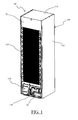
- Figure 1 there is shown in isometric view from behind a refrigerator according to an embodiment of the present invention.
- the refrigerator comprises a refrigerator cabinet 105, having two side walls (only one of which is visible, and is denoted 110), a top wall 115, a rear wall 120 and a bottom wall 415 (shown in Figure 4 ). Frontally, not visible in the drawing, the cabinet has an opening accessing the refrigerator inner compartment, where the food to be preserved can be stored, and a door, for closing the inner compartment opening.
- the refrigerator comprises a heat pump having a refrigerant compressor, a refrigerant liquefier or condenser, a metering or throttling device, and a refrigerant evaporator, all in fluid communication by means of pipes.
- the compressor denoted 125 in the drawing, is positioned in a recess 130 at the rear bottom of the cabinet 105.
- the condenser denoted 135 in the drawing, is an essentially flat external heat exchanger, with a winding piping for the refrigerant fluid, that is mounted onto the cabinet 105 (e.g. by means of brackets and screws) so as to extend along the cabinet rear wall 120, preferably along a significant length thereof, so as to feature a large heat exchange area.
- This is a typical arrangement for a static condenser (on the contrary, the refrigerators with dynamic condensers typically have box-shaped condensers that are relatively small in outer dimensions and are placed in the recess 130 where the compressor 125 is also placed
- ambient air usually flows by natural convection over the condenser 135, from the bottom to the top of the cabinet 105, exiting from an opening at the rear top of the cabinet.
- the natural flow of ambient air over the condenser is difficult.
- the refrigerator of the present invention comprises an air ventilation system 140 for augmenting the draft of ambient air over the condenser 135.
- the air ventilation system 140 advantageously comprises a fan or blower 305 and an air conveyor 205 conveying the air generated by the fan 305.
- the air conveyor 205 houses the fan 305.
- the fan 305 draws ambient air in from the outside environment (i.e., the kitchen) and the air conveyor 205 conveys the air taken in by the blower towards the condenser 135.
- the fan 305 and the associated air conveyor 205 are positioned in the recess 130, preferably aside the compressor 125, as visible in enlarged scale in Figure 2 .
- Figure 3 shows in exploded view the exemplary constitution of the air ventilation system 140 according to an embodiment of the present invention.
- the air conveyor 205 is advantageously provided with a fixing plate 315 for mounting it, by means of screws or bolts, onto a cross-plate 210 at the bottom of the recess 130 (to which the compressor 125 is also mounted).
- the fan 305 is preferably driven by an own motor 320 with horizontal axis, preferably coupled to the fan 305 through motor vibration absorbers 325, to damp vibrations.
- the air conveyor 205 is mounted onto the cross-plate 210 by interposition of further vibration absorbers 335, e.g. made of rubber, for further dumping vibrations.
- the air conveyor 205 defines an air conveying duct or channel 406 for conveying the air blown by the fan 305, and a motor chamber 407 housing the motor 320.
- the air conveyor 205 is preferably an assembly of three portions removably coupled to each other:
- the main hollow body 340 and the back cover 345 are shaped substantially as two half-shells to form together the air conveying duct 406 receiving and conveying the air blown by the fan 305.
- the air conveying duct 406 has a first horizontal section 406a (where the fan 305 is located) and a second vertical section 406b directed upwards.
- the motor chamber 407 is formed by the front part of the main hollow body 340 and the front cover 330.
- the motor chamber 407 has, in its lower part, an opening defining an air inlet 409a for the air conveyor 205, to suck the air entering the recess 130 from the outside of the refrigerator cabinet 105.
- the refrigerator cabinet 105 has, in its bottom, in particular between the bottom wall 415 and the cross-plate 210, an opening 420 to allow air to enter into the recess 130 from below the cabinet 105. As air is sucked from the outside, air circulation in the whole recess 130 is improved, so that also the compressor 125 is better cooled, thus increasing its efficiency.
- the air conveyor 205 is adapted to convey the air taken in by the fan 305 towards the top of the refrigerator cabinet 105.
- An air outlet 409b of the air conveyor 205 is located just below the condenser 135.
- hits absorbers 350 are attached to the outside of the back cover 345 for protecting the air conveyor 205 when the refrigerator 100 is installed in the kitchen, abutting the kitchen wall, and also dumps vibrations transmitted by the fan 305.
- FIG. 405 denotes the cross-sectioned walls of the kitchen furniture where the refrigerator is encased.
- an air gap 410 is left between the bottom wall 415 of the refrigerator cabinet 105 and a bottom wall 405-1 of the kitchen furniture 405.
- an air gap 420 is left between the rear wall of the refrigerator cabinet 105 and the rear wall 405-2 of the kitchen furniture 405.
- an air gap is similarly formed between the rear wall 120 of the refrigerator and the kitchen wall, laterally closed by the vertical side wall of the kitchen furniture where the refrigerator is encased.
- the refrigerator cabinet 105 has, in its bottom, in particular between the bottom wall 215 and the cross-plate 210, an opening 420 to allow air within the air gap 410 to enter into the recess 130.
- the fan 305 When the fan 305 is operating, it draws in ambient air from the air gap 410 into the recess 130 through the opening 420, and then into the air conveyor 205 through the air inlet 409a, and thanks to the air conveyor 205 the air is then forced to flow up along the air gap 420, thereby ventilating and cooling the condenser 135.
- the ambient air after having cooled the condenser 135, exits the air gap 420 and returns to the ambient through an opening provided at the top of the kitchen furniture wherein the refrigerator is encased.
- the walls 405-1 and 405-2 in Figure 4 could represent the floor and the wall of the kitchen against which the refrigerator is positioned. Even in the absence of a wall 405-2, the air conveyor 205 is able to properly direct the air blown by the fan 305 towards the condenser 135.
- the solution according to the present invention is very flexible. It allows improving the efficiency of existing refrigerators with static condenser in a way that does not impact their design, by simply adding, if desired, the air ventilation system 140, which can be accommodated in the recess 130 at the bottom of the refrigerator cabinet where the compressor is placed.
- a refrigerator with static condenser can easily be transformed into a refrigerator with forced-air condenser ventilation. This allows a manufacturer to have two distinct lines of product: one with static condenser ventilation and the other with forced condenser ventilation, but with a very small production cost (essentially just the cost of the fan 305 and associated air conveyor 205).
- the refrigerator control unit can be configured to selectively activate the fan 305, for example in response to a user command.
- the refrigerator control unit may be configured to cause the fan 305 to be activated only during the day and not at nighttime, so as to keep the noise level very low during the hours of sleep.
- the air conveyor can be a separate part with respect to the fan housing, coupled to the fan housing outlet so as to receive and guide towards the condenser the ambient air taken in by the fan.
- the fan instead of being an axial fan as described above, can be a different type of fan, for example a centrifugal fan.
Abstract
Description
- The present invention relates to appliances for food preservation, such as food refrigerators, particularly, although not limitatively, for domestic use.
- Food refrigerators essentially consist of a thermally-insulated compartment for the storage of food, and a heat pump that transfers heat from the inside of the refrigerator to its external environment so that the inside of the refrigerator is cooled to a temperature below the ambient temperature of the room (e.g., kitchen) where the appliance is located.
- In the heat pump, a refrigerant fluid undergoes a thermodynamic cycle. The refrigerant enters a compressor as low-pressure vapor at or slightly above the temperature of the refrigerator interior. In the compressor, the vapor is compressed and exits the compressor as high-pressure superheated vapor. The superheated vapor flows under pressure through coils or tubes forming a condenser, which are cooled by exposure to air in the room. The condenser cools the vapor, which condenses (liquefies). As the refrigerant leaves the condenser, it is still under pressure but only slightly above room temperature. The liquid refrigerant is forced through a metering or throttling device, also known as an expansion valve, to an area of much lower pressure. The sudden decrease in pressure results in a flash evaporation of part of the liquid. The latent heat absorbed by this flash evaporation is drawn mostly from adjacent still-liquid refrigerant, a phenomenon known as auto-refrigeration. This cold and partially vaporized refrigerant continues through the coils or tubes of an evaporator unit. The food storage compartment is in heat-exchange relationship with the evaporator; in the evaporator, the refrigerant completely vaporizes, drawing further latent heat from the compartment, which is thereby kept cold. The refrigerant leaves the evaporator, fully vaporized and slightly heated, and returns to the compressor inlet to continue the cycle.
- In household (domestic) refrigerators, two classes of refrigerant condensers are mainly used: static condensers or dynamic condensers.
- Static condensers comprise external heat exchangers extending essentially along the whole vertical length of the food storage compartment at the rear of the refrigerator cabinet (i.e., opposite to the front door), or skin condensers attached to the cabinet side walls. Static condensers are cooled by a natural (non-forced) flow of ambient air that flows by convection from the bottom to the top of the refrigerator cabinet.
- Dynamic condensers are usually box-shaped and placed in a recess at the bottom of the refrigerator cabinet where the compressor is also accommodated, or in a "worm module" under the cabinet. Dynamic condensers are cooled by a forced flow of ambient air, taken in by means of a fan. Examples of refrigerators with dynamic condensers are given in
DE 19933603 ,US 3,785,168 ,US 2,079,770 ,EP 1919973 . - Refrigerators are often fully embedded (built-in or encased) in the furniture of the kitchen, and this makes the ventilation (natural or forced) of the condensers more difficult.
- In refrigerators with dynamic condensers the path of ambient air cooling the condenser is typically "U"-shaped: ambient air is taken in through an opening at the bottom of the front of the kitchen furniture, caused to flow through the condenser, and expelled through another opening, which can also be at the bottom of the front of the kitchen furniture.
-
US 1,769,119 discloses a condensing system for household refrigerator using means for augmenting the draft passing over the compressor and condenser when the temperature of the environing atmosphere is such that the natural draft arrangement does not permit the refrigerating system to operate at its proper efficiency. A fan driven by a motor is provided, disposed in an apparatus compartment beneath the refrigerating chamber containing the compressor and its motor. - A proper ventilation of the condenser is important for cooling it down; a condenser that is not properly ventilated and cooled reduces the efficiency of the heat pump, and the refrigerator does not operate properly.
- Especially for built-in refrigerators to be encased in the kitchen furniture, but also for free-standing refrigerators, the solutions known in the art do not appear satisfactory.
- Refrigerators with dynamic condensers are useful in some specific applications (e.g., for so-called "under-top" refrigerators, intended to be encased in the kitchen furniture below the kitchen worktop: in this case there is no possibility for the ambient air to escape from the refrigerator top). However, the box-shaped condenser used in dynamic condenser refrigerators costs more than a condenser of the type used in static condenser refrigerators. Also, a condenser for a static condenser refrigerator has a great heat exchange surface (the condenser can occupy the large area at the back of the cabinet), beneficial to the refrigerant cooling down. Refrigerators with condensers of the type used in static condenser refrigerators are thus preferable in some circumstances, and they are also traditionally preferred in some regions of the world.
- The Applicant has observed that the solution disclosed in
US 1,769,119 does not work properly, especially in a built-in refrigerator, encased within the kitchen furniture. The apparatus compartment where the compressor is disposed, and where, according toUS 1,769,119 , the fan is also disposed, is a closed compartment with very small openings at the bottom and the top. A free fan disposed in this compartment is not able to move air from the small apertures at the bottom and then to force the air up to the condenser, which is located out of the compartment, along the back of the refrigerator. In a built-in appliance a free fan positioned as described byUS 1,769,119 is only able to recirculate air inside the compressor compartment; the compressor is still cooled by the natural air flow that moves by convection. - According to an embodiment of the present invention, a food refrigerator is provided, comprising a cabinet and a heat pump for submitting a refrigerant fluid to a thermodynamic cycle, wherein the heat pump comprises a refrigerant condenser mounted on a back wall of the cabinet and extending along said back wall.
- The food refrigerator comprises a forced air ventilation system for ventilating the condenser. The forced air ventilation system comprises at least one blower for drawing in air from the outside environment, and an air conveyor associated with the at least one blower for directing the ambient air drawn in and propelled by the at least one blower towards the refrigerant condenser.
- Advantageously, the at least one blower and the air conveyor are housed in a recess of the refrigerator cabinet at the bottom of the refrigerator cabinet, below the refrigerant condenser.
- In an embodiment of the invention, the air conveyor may house the blower.
- In an embodiment of the present invention, the air conveyor may comprise a first portion housing the blower, and a removable second portion configured to be mounted to the first portion for defining an air channel for the air expelled by the blower.
- Preferably, the first and the second portions are configured so as to allow access to the blower when the second portion is removed.
- In an embodiment of the present invention, the air conveyor may comprise a first portion housing the blower and at least part of a motor activating the blower, and a removable third portion configured to be mounted to the first portion to cover part of the motor.
- Preferably, the first and the second portions are configured so as to allow access to the motor when the third portion is removed.
- Advantageously, the air conveyor is provided with a plate for mounting it to a cross-plate at the bottom of a recess of the refrigerator cabinet where the air conveyor is housed.
- The food refrigerator may advantageously comprise a control unit for selectively activating the blower.
- These and other features and advantages of the present invention will be made apparent by the following detailed description of an embodiment thereof. The description is provided merely by way of non-limiting example, and makes reference to the annexed drawings, wherein:
-
Figure 1 shows in isometric view from the back a refrigerator according to an embodiment of the present invention; -
Figure 2 shows in enlarged scale a detail of the bottom of the refrigerator shown inFigure 1 ; -
Figure 3 shows in exploded view a blower according to an embodiment of the present invention for the forced ventilation of the refrigerator condenser; and -
Figure 4 is a schematic cross-sectional view illustrating the operation of the refrigerator ofFigures 1 and2 . - Referring to the drawings, in
Figure 1 there is shown in isometric view from behind a refrigerator according to an embodiment of the present invention. - The refrigerator comprises a
refrigerator cabinet 105, having two side walls (only one of which is visible, and is denoted 110), atop wall 115, arear wall 120 and a bottom wall 415 (shown inFigure 4 ). Frontally, not visible in the drawing, the cabinet has an opening accessing the refrigerator inner compartment, where the food to be preserved can be stored, and a door, for closing the inner compartment opening. - The refrigerator comprises a heat pump having a refrigerant compressor, a refrigerant liquefier or condenser, a metering or throttling device, and a refrigerant evaporator, all in fluid communication by means of pipes. The compressor, denoted 125 in the drawing, is positioned in a
recess 130 at the rear bottom of thecabinet 105. The condenser, denoted 135 in the drawing, is an essentially flat external heat exchanger, with a winding piping for the refrigerant fluid, that is mounted onto the cabinet 105 (e.g. by means of brackets and screws) so as to extend along the cabinetrear wall 120, preferably along a significant length thereof, so as to feature a large heat exchange area. This is a typical arrangement for a static condenser (on the contrary, the refrigerators with dynamic condensers typically have box-shaped condensers that are relatively small in outer dimensions and are placed in therecess 130 where thecompressor 125 is also placed). - In a refrigerator with a static condenser, ambient air usually flows by natural convection over the
condenser 135, from the bottom to the top of thecabinet 105, exiting from an opening at the rear top of the cabinet. However, when the refrigerator is encased, built-in the kitchen furniture, the natural flow of ambient air over the condenser is difficult. - According to a preferred embodiment, the refrigerator of the present invention comprises an
air ventilation system 140 for augmenting the draft of ambient air over thecondenser 135. - Referring also to
Figures 2 and3 , theair ventilation system 140 advantageously comprises a fan orblower 305 and anair conveyor 205 conveying the air generated by thefan 305. In the preferred embodiment here described, theair conveyor 205 houses thefan 305. Thefan 305 draws ambient air in from the outside environment (i.e., the kitchen) and theair conveyor 205 conveys the air taken in by the blower towards thecondenser 135. Advantageously, thefan 305 and the associatedair conveyor 205 are positioned in therecess 130, preferably aside thecompressor 125, as visible in enlarged scale inFigure 2 . -
Figure 3 shows in exploded view the exemplary constitution of theair ventilation system 140 according to an embodiment of the present invention. - The
air conveyor 205 is advantageously provided with a fixingplate 315 for mounting it, by means of screws or bolts, onto a cross-plate 210 at the bottom of the recess 130 (to which thecompressor 125 is also mounted). Thefan 305 is preferably driven by anown motor 320 with horizontal axis, preferably coupled to thefan 305 throughmotor vibration absorbers 325, to damp vibrations. Preferably, theair conveyor 205 is mounted onto the cross-plate 210 by interposition offurther vibration absorbers 335, e.g. made of rubber, for further dumping vibrations. - Preferably, as shown in
Figure 4 , theair conveyor 205 defines an air conveying duct orchannel 406 for conveying the air blown by thefan 305, and amotor chamber 407 housing themotor 320. - With reference to
Figure 3 , theair conveyor 205 is preferably an assembly of three portions removably coupled to each other: - a main
hollow body 340 housing thefan 305 and partly themotor 320, - a
front cover 330, coupled to themain body 340 by means of screws and giving access to themotor 320 when removed, and - a
back cover 345, coupled to themain body 340 by means of snap fits and giving access to thefan 305 when removed. - It is clear that other kind of coupling means can be used as well to couple the three portions.
- The main
hollow body 340 and theback cover 345 are shaped substantially as two half-shells to form together theair conveying duct 406 receiving and conveying the air blown by thefan 305. - In particular:
- the main
hollow body 340 has a lowercylindrical portion 340a with horizontal axis defining a chamber hosting thefan 305 and an uppervertical wall 340b extending upwards from the back end of thecylindrical portion 340a, and - the
back cover 345 is a substantially planar body having a lowercircular portion 345a matching with the perimeter of thecylindrical portion 340a of the mainhollow body 340, and avertical wall 345b extending upwards from the lowercircular portion 345a and matching with thevertical wall 340b of the mainhollow body 340. - Thus, as shown in
Figure 4 , theair conveying duct 406 has a firsthorizontal section 406a (where thefan 305 is located) and a secondvertical section 406b directed upwards. - The
motor chamber 407 is formed by the front part of the mainhollow body 340 and thefront cover 330. Themotor chamber 407 has, in its lower part, an opening defining anair inlet 409a for theair conveyor 205, to suck the air entering therecess 130 from the outside of therefrigerator cabinet 105. Moreover, therefrigerator cabinet 105 has, in its bottom, in particular between thebottom wall 415 and the cross-plate 210, anopening 420 to allow air to enter into therecess 130 from below thecabinet 105. As air is sucked from the outside, air circulation in thewhole recess 130 is improved, so that also thecompressor 125 is better cooled, thus increasing its efficiency. - Accordingly, the
air conveyor 205 is adapted to convey the air taken in by thefan 305 towards the top of therefrigerator cabinet 105. Anair outlet 409b of theair conveyor 205 is located just below thecondenser 135. - Advantageously, hits
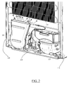
absorbers 350 are attached to the outside of theback cover 345 for protecting theair conveyor 205 when therefrigerator 100 is installed in the kitchen, abutting the kitchen wall, and also dumps vibrations transmitted by thefan 305. - The operations of the refrigerator of the present invention will be herein below described with reference to the schematic cross-sectional view
Figure 4 , illustrating the refrigerator encased in a kitchen furniture. In the drawing, 405 denotes the cross-sectioned walls of the kitchen furniture where the refrigerator is encased. When the refrigerator is encased in the kitchen furniture, anair gap 410 is left between thebottom wall 415 of therefrigerator cabinet 105 and a bottom wall 405-1 of thekitchen furniture 405. Similarly, anair gap 420 is left between the rear wall of therefrigerator cabinet 105 and the rear wall 405-2 of thekitchen furniture 405. When thekitchen furniture 405 does not have a rear wall, an air gap is similarly formed between therear wall 120 of the refrigerator and the kitchen wall, laterally closed by the vertical side wall of the kitchen furniture where the refrigerator is encased. - Moreover, the
refrigerator cabinet 105 has, in its bottom, in particular between the bottom wall 215 and the cross-plate 210, anopening 420 to allow air within theair gap 410 to enter into therecess 130. - When the
fan 305 is operating, it draws in ambient air from theair gap 410 into therecess 130 through theopening 420, and then into theair conveyor 205 through theair inlet 409a, and thanks to theair conveyor 205 the air is then forced to flow up along theair gap 420, thereby ventilating and cooling thecondenser 135. The ambient air, after having cooled thecondenser 135, exits theair gap 420 and returns to the ambient through an opening provided at the top of the kitchen furniture wherein the refrigerator is encased. - If the refrigerator is not built-in but free-standing, the operations are exactly the same, and the walls 405-1 and 405-2 in
Figure 4 could represent the floor and the wall of the kitchen against which the refrigerator is positioned. Even in the absence of a wall 405-2, theair conveyor 205 is able to properly direct the air blown by thefan 305 towards thecondenser 135. - The solution according to the present invention is very flexible. It allows improving the efficiency of existing refrigerators with static condenser in a way that does not impact their design, by simply adding, if desired, the
air ventilation system 140, which can be accommodated in therecess 130 at the bottom of the refrigerator cabinet where the compressor is placed. Thus, thanks to the solution of the present invention, a refrigerator with static condenser can easily be transformed into a refrigerator with forced-air condenser ventilation. This allows a manufacturer to have two distinct lines of product: one with static condenser ventilation and the other with forced condenser ventilation, but with a very small production cost (essentially just the cost of thefan 305 and associated air conveyor 205). - Advantageously, the refrigerator control unit can be configured to selectively activate the
fan 305, for example in response to a user command. For example, the refrigerator control unit may be configured to cause thefan 305 to be activated only during the day and not at nighttime, so as to keep the noise level very low during the hours of sleep. - In the foregoing, an exemplary embodiment of the present invention has been described. Those skilled in the art will readily understand that several modifications to the described embodiments are possible. For example, in alternative embodiments the air conveyor can be a separate part with respect to the fan housing, coupled to the fan housing outlet so as to receive and guide towards the condenser the ambient air taken in by the fan. The fan, instead of being an axial fan as described above, can be a different type of fan, for example a centrifugal fan.
Claims (9)
- A food refrigerator comprising a cabinet (105), a heat pump for submitting a refrigerant fluid to a thermodynamic cycle, wherein the heat pump comprises a refrigerant condenser (135) mounted on a back wall (120) of the cabinet and extending along said back wall, and a forced air ventilation system (140) for ventilating the condenser, characterized in that the forced air ventilation system comprises at least one blower (305) for drawing in air from the outside environment, and an air conveyor (205) associated with the at least one blower for directing the ambient air drawn in and propelled by the at least one blower towards the refrigerant condenser.
- The food refrigerator according to claim 1, wherein the at least one blower and the air conveyor are housed in a recess (130) of the refrigerator cabinet at the bottom of the refrigerator cabinet, below the refrigerant condenser.
- The food refrigerator of claim 1 or 2, wherein the air conveyor houses the blower.
- The food refrigerator of any of the preceding claims, wherein the air conveyor comprises a first portion (340) housing the blower, and a removable second portion (345) configured to be mounted to the first portion for defining an air channel for the air expelled by the blower.
- The food refrigerator of claim 4, wherein the first and the second portions are configured so as to allow access to the blower when the second portion is removed.
- The food refrigerator of any of the preceding claims, wherein the air conveyor comprises a first portion (340) housing the blower and at least part of a motor activating the blower, and a removable third portion (345) configured to be mounted to the first portion to cover part of the motor.
- The food refrigerator of claim 6, wherein the first and the second portions are configured so as to allow access to the motor when the third portion is removed.
- The food refrigerator of any of the preceding claims, wherein the air conveyor is provided with a plate (315) for mounting it to a cross-plate (210) at the bottom of a recess (130) of the refrigerator cabinet where the air conveyor is housed.
- The food refrigerator of any one of the preceding claims, comprising a control unit for selectively activating the blower.
Priority Applications (1)
| Application Number | Priority Date | Filing Date | Title |
|---|---|---|---|
| EP12197386.1A EP2743618B1 (en) | 2012-12-17 | 2012-12-17 | Refrigerator for foods |
Applications Claiming Priority (1)
| Application Number | Priority Date | Filing Date | Title |
|---|---|---|---|
| EP12197386.1A EP2743618B1 (en) | 2012-12-17 | 2012-12-17 | Refrigerator for foods |
Publications (2)
| Publication Number | Publication Date |
|---|---|
| EP2743618A1 true EP2743618A1 (en) | 2014-06-18 |
| EP2743618B1 EP2743618B1 (en) | 2016-03-02 |
Family
ID=47552755
Family Applications (1)
| Application Number | Title | Priority Date | Filing Date |
|---|---|---|---|
| EP12197386.1A Active EP2743618B1 (en) | 2012-12-17 | 2012-12-17 | Refrigerator for foods |
Country Status (1)
| Country | Link |
|---|---|
| EP (1) | EP2743618B1 (en) |
Cited By (6)
| Publication number | Priority date | Publication date | Assignee | Title |
|---|---|---|---|---|
| DE102017003481A1 (en) | 2017-01-23 | 2018-07-26 | Liebherr-Hausgeräte Ochsenhausen GmbH | Fridge and / or freezer |
| CN114076455A (en) * | 2020-08-18 | 2022-02-22 | 青岛海尔电冰箱有限公司 | Embedded refrigerator |
| CN114076462A (en) * | 2020-08-18 | 2022-02-22 | 青岛海尔电冰箱有限公司 | Embedded refrigerator |
| WO2023105047A1 (en) | 2021-12-10 | 2023-06-15 | BSH Hausgeräte GmbH | Heat exchanger assembly for a refrigeration device, and refrigeration device comprising same |
| DE102022208905A1 (en) | 2022-08-29 | 2024-02-29 | BSH Hausgeräte GmbH | Refrigeration device and heat exchanger assembly for a refrigeration device |
| DE102022213434B3 (en) | 2022-12-12 | 2024-03-28 | BSH Hausgeräte GmbH | Refrigeration device |
Citations (8)
| Publication number | Priority date | Publication date | Assignee | Title |
|---|---|---|---|---|
| US1769119A (en) | 1928-01-06 | 1930-07-01 | Chicago Pneumatic Tool Co | Condensing system |
| US2079770A (en) | 1936-03-31 | 1937-05-11 | Robinson James Macomber | Combination bathtub and shower |
| US3785168A (en) | 1972-12-18 | 1974-01-15 | Gen Electric | Household refrigerator |
| US4089187A (en) * | 1975-06-23 | 1978-05-16 | General Electric Company | Condenser-air flow system of a household refrigerator |
| US5743109A (en) * | 1993-12-15 | 1998-04-28 | Schulak; Edward R. | Energy efficient domestic refrigeration system |
| DE19906742A1 (en) * | 1999-02-18 | 2000-08-31 | Fischer Udo | Refrigerator, especially plug-in cooling shelves, has liquefier mounted on rear wall of refrigerator to extend essentially over entire lateral extent of refrigerator |
| DE19933603A1 (en) | 1999-07-17 | 2001-01-18 | Aeg Hausgeraete Gmbh | Cooling or freezing apparatus for installation in furniture surround has in lower region of back side of apparatus, niche in which compressor, liquefier and fan are located with opening downwards |
| EP1919973A1 (en) | 2005-08-11 | 2008-05-14 | University Of Massachusetts Lowell | Novel methods for forming copolymers comprising olefin and protected or unprotected hydroxystyrene units |
-
2012
- 2012-12-17 EP EP12197386.1A patent/EP2743618B1/en active Active
Patent Citations (8)
| Publication number | Priority date | Publication date | Assignee | Title |
|---|---|---|---|---|
| US1769119A (en) | 1928-01-06 | 1930-07-01 | Chicago Pneumatic Tool Co | Condensing system |
| US2079770A (en) | 1936-03-31 | 1937-05-11 | Robinson James Macomber | Combination bathtub and shower |
| US3785168A (en) | 1972-12-18 | 1974-01-15 | Gen Electric | Household refrigerator |
| US4089187A (en) * | 1975-06-23 | 1978-05-16 | General Electric Company | Condenser-air flow system of a household refrigerator |
| US5743109A (en) * | 1993-12-15 | 1998-04-28 | Schulak; Edward R. | Energy efficient domestic refrigeration system |
| DE19906742A1 (en) * | 1999-02-18 | 2000-08-31 | Fischer Udo | Refrigerator, especially plug-in cooling shelves, has liquefier mounted on rear wall of refrigerator to extend essentially over entire lateral extent of refrigerator |
| DE19933603A1 (en) | 1999-07-17 | 2001-01-18 | Aeg Hausgeraete Gmbh | Cooling or freezing apparatus for installation in furniture surround has in lower region of back side of apparatus, niche in which compressor, liquefier and fan are located with opening downwards |
| EP1919973A1 (en) | 2005-08-11 | 2008-05-14 | University Of Massachusetts Lowell | Novel methods for forming copolymers comprising olefin and protected or unprotected hydroxystyrene units |
Cited By (11)
| Publication number | Priority date | Publication date | Assignee | Title |
|---|---|---|---|---|
| DE102017003481A1 (en) | 2017-01-23 | 2018-07-26 | Liebherr-Hausgeräte Ochsenhausen GmbH | Fridge and / or freezer |
| CN114076455A (en) * | 2020-08-18 | 2022-02-22 | 青岛海尔电冰箱有限公司 | Embedded refrigerator |
| CN114076462A (en) * | 2020-08-18 | 2022-02-22 | 青岛海尔电冰箱有限公司 | Embedded refrigerator |
| WO2022037382A1 (en) * | 2020-08-18 | 2022-02-24 | 青岛海尔电冰箱有限公司 | Embedded refrigerator |
| CN114076462B (en) * | 2020-08-18 | 2022-12-16 | 青岛海尔电冰箱有限公司 | Embedded refrigerator |
| CN114076455B (en) * | 2020-08-18 | 2023-06-16 | 青岛海尔电冰箱有限公司 | Embedded refrigerator |
| WO2023105047A1 (en) | 2021-12-10 | 2023-06-15 | BSH Hausgeräte GmbH | Heat exchanger assembly for a refrigeration device, and refrigeration device comprising same |
| DE102021214123A1 (en) | 2021-12-10 | 2023-06-15 | BSH Hausgeräte GmbH | Refrigeration device and heat exchanger assembly for a refrigeration device |
| DE102022208905A1 (en) | 2022-08-29 | 2024-02-29 | BSH Hausgeräte GmbH | Refrigeration device and heat exchanger assembly for a refrigeration device |
| EP4332476A1 (en) | 2022-08-29 | 2024-03-06 | BSH Hausgeräte GmbH | Refrigeration device and heat exchanger assembly for a refrigeration device |
| DE102022213434B3 (en) | 2022-12-12 | 2024-03-28 | BSH Hausgeräte GmbH | Refrigeration device |
Also Published As
| Publication number | Publication date |
|---|---|
| EP2743618B1 (en) | 2016-03-02 |
Similar Documents
| Publication | Publication Date | Title |
|---|---|---|
| EP2743618B1 (en) | Refrigerator for foods | |
| KR20080083537A (en) | Refrigerator | |
| WO2005003658A3 (en) | Cabinet refrigerating system | |
| EP2174083A2 (en) | Refrigerator | |
| EP1384963B1 (en) | Built-in refrigerator | |
| JP2009134531A (en) | Electronic device cooling system | |
| JP2007064601A (en) | Refrigerator | |
| KR20110107653A (en) | Refrigerator | |
| JP2009134541A (en) | Electronic equipment cooling apparatus | |
| KR100950846B1 (en) | Refrigerator | |
| EP1604159B1 (en) | Refrigerator with noise reduction system | |
| JP2014048029A (en) | Refrigerator | |
| JP2007064598A (en) | Refrigerator | |
| JP2001099541A (en) | Refrigerator | |
| CN210267846U (en) | New-type commercial freezer refrigerating system structure | |
| WO2020181609A1 (en) | Integrated kitchen air conditioner | |
| KR20060110150A (en) | Damper of a refrigerator | |
| JP2006343035A (en) | Refrigerator | |
| BR102015028999A2 (en) | cabinet cooling system and forced air cooling cabinet | |
| KR102614569B1 (en) | Refrigerator incorporated with air conditioner and a system for discharging air including the same | |
| RU2313048C1 (en) | Refrigerator | |
| WO2020207321A1 (en) | Fan assembly for electric appliance and refrigeration electric appliance | |
| EP2350544B1 (en) | A cooling device comprising an evaporation tray | |
| KR20130120022A (en) | Refrigerator | |
| US20070028644A1 (en) | Two-part cooling device |
Legal Events
| Date | Code | Title | Description |
|---|---|---|---|
| PUAI | Public reference made under article 153(3) epc to a published international application that has entered the european phase |
Free format text: ORIGINAL CODE: 0009012 |
|
| 17P | Request for examination filed |
Effective date: 20121217 |
|
| AK | Designated contracting states |
Kind code of ref document: A1 Designated state(s): AL AT BE BG CH CY CZ DE DK EE ES FI FR GB GR HR HU IE IS IT LI LT LU LV MC MK MT NL NO PL PT RO RS SE SI SK SM TR |
|
| AX | Request for extension of the european patent |
Extension state: BA ME |
|
| R17P | Request for examination filed (corrected) |
Effective date: 20150417 |
|
| RBV | Designated contracting states (corrected) |
Designated state(s): AL AT BE BG CH CY CZ DE DK EE ES FI FR GB GR HR HU IE IS IT LI LT LU LV MC MK MT NL NO PL PT RO RS SE SI SK SM TR |
|
| GRAP | Despatch of communication of intention to grant a patent |
Free format text: ORIGINAL CODE: EPIDOSNIGR1 |
|
| INTG | Intention to grant announced |
Effective date: 20150824 |
|
| GRAS | Grant fee paid |
Free format text: ORIGINAL CODE: EPIDOSNIGR3 |
|
| GRAA | (expected) grant |
Free format text: ORIGINAL CODE: 0009210 |
|
| AK | Designated contracting states |
Kind code of ref document: B1 Designated state(s): AL AT BE BG CH CY CZ DE DK EE ES FI FR GB GR HR HU IE IS IT LI LT LU LV MC MK MT NL NO PL PT RO RS SE SI SK SM TR |
|
| REG | Reference to a national code |
Ref country code: GB Ref legal event code: FG4D |
|
| REG | Reference to a national code |
Ref country code: AT Ref legal event code: REF Ref document number: 778332 Country of ref document: AT Kind code of ref document: T Effective date: 20160315 Ref country code: CH Ref legal event code: EP |
|
| REG | Reference to a national code |
Ref country code: IE Ref legal event code: FG4D |
|
| REG | Reference to a national code |
Ref country code: DE Ref legal event code: R096 Ref document number: 602012015147 Country of ref document: DE |
|
| REG | Reference to a national code |
Ref country code: NL Ref legal event code: MP Effective date: 20160302 |
|
| REG | Reference to a national code |
Ref country code: LT Ref legal event code: MG4D |
|
| REG | Reference to a national code |
Ref country code: AT Ref legal event code: MK05 Ref document number: 778332 Country of ref document: AT Kind code of ref document: T Effective date: 20160302 |
|
| PG25 | Lapsed in a contracting state [announced via postgrant information from national office to epo] |
Ref country code: NO Free format text: LAPSE BECAUSE OF FAILURE TO SUBMIT A TRANSLATION OF THE DESCRIPTION OR TO PAY THE FEE WITHIN THE PRESCRIBED TIME-LIMIT Effective date: 20160602 Ref country code: ES Free format text: LAPSE BECAUSE OF FAILURE TO SUBMIT A TRANSLATION OF THE DESCRIPTION OR TO PAY THE FEE WITHIN THE PRESCRIBED TIME-LIMIT Effective date: 20160302 Ref country code: GR Free format text: LAPSE BECAUSE OF FAILURE TO SUBMIT A TRANSLATION OF THE DESCRIPTION OR TO PAY THE FEE WITHIN THE PRESCRIBED TIME-LIMIT Effective date: 20160603 Ref country code: FI Free format text: LAPSE BECAUSE OF FAILURE TO SUBMIT A TRANSLATION OF THE DESCRIPTION OR TO PAY THE FEE WITHIN THE PRESCRIBED TIME-LIMIT Effective date: 20160302 Ref country code: HR Free format text: LAPSE BECAUSE OF FAILURE TO SUBMIT A TRANSLATION OF THE DESCRIPTION OR TO PAY THE FEE WITHIN THE PRESCRIBED TIME-LIMIT Effective date: 20160302 |
|
| PG25 | Lapsed in a contracting state [announced via postgrant information from national office to epo] |
Ref country code: AT Free format text: LAPSE BECAUSE OF FAILURE TO SUBMIT A TRANSLATION OF THE DESCRIPTION OR TO PAY THE FEE WITHIN THE PRESCRIBED TIME-LIMIT Effective date: 20160302 Ref country code: LT Free format text: LAPSE BECAUSE OF FAILURE TO SUBMIT A TRANSLATION OF THE DESCRIPTION OR TO PAY THE FEE WITHIN THE PRESCRIBED TIME-LIMIT Effective date: 20160302 Ref country code: RS Free format text: LAPSE BECAUSE OF FAILURE TO SUBMIT A TRANSLATION OF THE DESCRIPTION OR TO PAY THE FEE WITHIN THE PRESCRIBED TIME-LIMIT Effective date: 20160302 Ref country code: NL Free format text: LAPSE BECAUSE OF FAILURE TO SUBMIT A TRANSLATION OF THE DESCRIPTION OR TO PAY THE FEE WITHIN THE PRESCRIBED TIME-LIMIT Effective date: 20160302 Ref country code: PL Free format text: LAPSE BECAUSE OF FAILURE TO SUBMIT A TRANSLATION OF THE DESCRIPTION OR TO PAY THE FEE WITHIN THE PRESCRIBED TIME-LIMIT Effective date: 20160302 Ref country code: LV Free format text: LAPSE BECAUSE OF FAILURE TO SUBMIT A TRANSLATION OF THE DESCRIPTION OR TO PAY THE FEE WITHIN THE PRESCRIBED TIME-LIMIT Effective date: 20160302 Ref country code: SE Free format text: LAPSE BECAUSE OF FAILURE TO SUBMIT A TRANSLATION OF THE DESCRIPTION OR TO PAY THE FEE WITHIN THE PRESCRIBED TIME-LIMIT Effective date: 20160302 |
|
| PG25 | Lapsed in a contracting state [announced via postgrant information from national office to epo] |
Ref country code: EE Free format text: LAPSE BECAUSE OF FAILURE TO SUBMIT A TRANSLATION OF THE DESCRIPTION OR TO PAY THE FEE WITHIN THE PRESCRIBED TIME-LIMIT Effective date: 20160302 Ref country code: IS Free format text: LAPSE BECAUSE OF FAILURE TO SUBMIT A TRANSLATION OF THE DESCRIPTION OR TO PAY THE FEE WITHIN THE PRESCRIBED TIME-LIMIT Effective date: 20160702 |
|
| PG25 | Lapsed in a contracting state [announced via postgrant information from national office to epo] |
Ref country code: RO Free format text: LAPSE BECAUSE OF FAILURE TO SUBMIT A TRANSLATION OF THE DESCRIPTION OR TO PAY THE FEE WITHIN THE PRESCRIBED TIME-LIMIT Effective date: 20160302 Ref country code: SM Free format text: LAPSE BECAUSE OF FAILURE TO SUBMIT A TRANSLATION OF THE DESCRIPTION OR TO PAY THE FEE WITHIN THE PRESCRIBED TIME-LIMIT Effective date: 20160302 Ref country code: PT Free format text: LAPSE BECAUSE OF FAILURE TO SUBMIT A TRANSLATION OF THE DESCRIPTION OR TO PAY THE FEE WITHIN THE PRESCRIBED TIME-LIMIT Effective date: 20160704 Ref country code: CZ Free format text: LAPSE BECAUSE OF FAILURE TO SUBMIT A TRANSLATION OF THE DESCRIPTION OR TO PAY THE FEE WITHIN THE PRESCRIBED TIME-LIMIT Effective date: 20160302 Ref country code: SK Free format text: LAPSE BECAUSE OF FAILURE TO SUBMIT A TRANSLATION OF THE DESCRIPTION OR TO PAY THE FEE WITHIN THE PRESCRIBED TIME-LIMIT Effective date: 20160302 |
|
| REG | Reference to a national code |
Ref country code: DE Ref legal event code: R097 Ref document number: 602012015147 Country of ref document: DE |
|
| PG25 | Lapsed in a contracting state [announced via postgrant information from national office to epo] |
Ref country code: BE Free format text: LAPSE BECAUSE OF FAILURE TO SUBMIT A TRANSLATION OF THE DESCRIPTION OR TO PAY THE FEE WITHIN THE PRESCRIBED TIME-LIMIT Effective date: 20160302 |
|
| PLBE | No opposition filed within time limit |
Free format text: ORIGINAL CODE: 0009261 |
|
| STAA | Information on the status of an ep patent application or granted ep patent |
Free format text: STATUS: NO OPPOSITION FILED WITHIN TIME LIMIT |
|
| PG25 | Lapsed in a contracting state [announced via postgrant information from national office to epo] |
Ref country code: DK Free format text: LAPSE BECAUSE OF FAILURE TO SUBMIT A TRANSLATION OF THE DESCRIPTION OR TO PAY THE FEE WITHIN THE PRESCRIBED TIME-LIMIT Effective date: 20160302 |
|
| 26N | No opposition filed |
Effective date: 20161205 |
|
| PG25 | Lapsed in a contracting state [announced via postgrant information from national office to epo] |
Ref country code: SI Free format text: LAPSE BECAUSE OF FAILURE TO SUBMIT A TRANSLATION OF THE DESCRIPTION OR TO PAY THE FEE WITHIN THE PRESCRIBED TIME-LIMIT Effective date: 20160302 Ref country code: BG Free format text: LAPSE BECAUSE OF FAILURE TO SUBMIT A TRANSLATION OF THE DESCRIPTION OR TO PAY THE FEE WITHIN THE PRESCRIBED TIME-LIMIT Effective date: 20160602 |
|
| REG | Reference to a national code |
Ref country code: CH Ref legal event code: PL |
|
| GBPC | Gb: european patent ceased through non-payment of renewal fee |
Effective date: 20161217 |
|
| PG25 | Lapsed in a contracting state [announced via postgrant information from national office to epo] |
Ref country code: MC Free format text: LAPSE BECAUSE OF FAILURE TO SUBMIT A TRANSLATION OF THE DESCRIPTION OR TO PAY THE FEE WITHIN THE PRESCRIBED TIME-LIMIT Effective date: 20160302 |
|
| REG | Reference to a national code |
Ref country code: FR Ref legal event code: ST Effective date: 20170831 |
|
| REG | Reference to a national code |
Ref country code: IE Ref legal event code: MM4A |
|
| PG25 | Lapsed in a contracting state [announced via postgrant information from national office to epo] |
Ref country code: LI Free format text: LAPSE BECAUSE OF NON-PAYMENT OF DUE FEES Effective date: 20161231 Ref country code: CH Free format text: LAPSE BECAUSE OF NON-PAYMENT OF DUE FEES Effective date: 20161231 Ref country code: FR Free format text: LAPSE BECAUSE OF NON-PAYMENT OF DUE FEES Effective date: 20170102 Ref country code: LU Free format text: LAPSE BECAUSE OF NON-PAYMENT OF DUE FEES Effective date: 20161217 |
|
| PG25 | Lapsed in a contracting state [announced via postgrant information from national office to epo] |
Ref country code: GB Free format text: LAPSE BECAUSE OF NON-PAYMENT OF DUE FEES Effective date: 20161217 Ref country code: IE Free format text: LAPSE BECAUSE OF NON-PAYMENT OF DUE FEES Effective date: 20161217 |
|
| PG25 | Lapsed in a contracting state [announced via postgrant information from national office to epo] |
Ref country code: HU Free format text: LAPSE BECAUSE OF FAILURE TO SUBMIT A TRANSLATION OF THE DESCRIPTION OR TO PAY THE FEE WITHIN THE PRESCRIBED TIME-LIMIT; INVALID AB INITIO Effective date: 20121217 |
|
| PG25 | Lapsed in a contracting state [announced via postgrant information from national office to epo] |
Ref country code: MK Free format text: LAPSE BECAUSE OF FAILURE TO SUBMIT A TRANSLATION OF THE DESCRIPTION OR TO PAY THE FEE WITHIN THE PRESCRIBED TIME-LIMIT Effective date: 20160302 Ref country code: CY Free format text: LAPSE BECAUSE OF FAILURE TO SUBMIT A TRANSLATION OF THE DESCRIPTION OR TO PAY THE FEE WITHIN THE PRESCRIBED TIME-LIMIT Effective date: 20160302 |
|
| PG25 | Lapsed in a contracting state [announced via postgrant information from national office to epo] |
Ref country code: MT Free format text: LAPSE BECAUSE OF NON-PAYMENT OF DUE FEES Effective date: 20161217 |
|
| PG25 | Lapsed in a contracting state [announced via postgrant information from national office to epo] |
Ref country code: AL Free format text: LAPSE BECAUSE OF FAILURE TO SUBMIT A TRANSLATION OF THE DESCRIPTION OR TO PAY THE FEE WITHIN THE PRESCRIBED TIME-LIMIT Effective date: 20160302 Ref country code: TR Free format text: LAPSE BECAUSE OF FAILURE TO SUBMIT A TRANSLATION OF THE DESCRIPTION OR TO PAY THE FEE WITHIN THE PRESCRIBED TIME-LIMIT Effective date: 20160302 |
|
| PGFP | Annual fee paid to national office [announced via postgrant information from national office to epo] |
Ref country code: DE Payment date: 20221213 Year of fee payment: 11 |
|
| P01 | Opt-out of the competence of the unified patent court (upc) registered |
Effective date: 20230625 |
|
| PGFP | Annual fee paid to national office [announced via postgrant information from national office to epo] |
Ref country code: IT Payment date: 20231221 Year of fee payment: 12 |