EP2743373B1 - Metering unit and use of the same - Google Patents
Metering unit and use of the same Download PDFInfo
- Publication number
- EP2743373B1 EP2743373B1 EP13192939.0A EP13192939A EP2743373B1 EP 2743373 B1 EP2743373 B1 EP 2743373B1 EP 13192939 A EP13192939 A EP 13192939A EP 2743373 B1 EP2743373 B1 EP 2743373B1
- Authority
- EP
- European Patent Office
- Prior art keywords
- precursor
- gas stream
- dosing
- gas
- duct
- Prior art date
- Legal status (The legal status is an assumption and is not a legal conclusion. Google has not performed a legal analysis and makes no representation as to the accuracy of the status listed.)
- Active
Links
- 239000002243 precursor Substances 0.000 claims description 73
- 239000002245 particle Substances 0.000 claims description 22
- 238000000034 method Methods 0.000 claims description 18
- 239000000758 substrate Substances 0.000 claims description 17
- 239000002105 nanoparticle Substances 0.000 claims description 13
- 239000007788 liquid Substances 0.000 claims description 9
- 239000007787 solid Substances 0.000 claims description 8
- 238000004140 cleaning Methods 0.000 claims description 7
- 238000002347 injection Methods 0.000 claims description 7
- 239000007924 injection Substances 0.000 claims description 7
- 238000000151 deposition Methods 0.000 claims description 6
- 239000007795 chemical reaction product Substances 0.000 claims description 5
- 229910052709 silver Inorganic materials 0.000 claims description 4
- 229910052802 copper Inorganic materials 0.000 claims description 3
- 239000010949 copper Substances 0.000 claims description 3
- 239000004332 silver Substances 0.000 claims description 3
- RYGMFSIKBFXOCR-UHFFFAOYSA-N Copper Chemical compound [Cu] RYGMFSIKBFXOCR-UHFFFAOYSA-N 0.000 claims description 2
- 230000008021 deposition Effects 0.000 claims 1
- 239000007789 gas Substances 0.000 description 57
- 238000000576 coating method Methods 0.000 description 11
- 239000011248 coating agent Substances 0.000 description 9
- 230000008569 process Effects 0.000 description 8
- 230000000694 effects Effects 0.000 description 5
- QGZKDVFQNNGYKY-UHFFFAOYSA-N Ammonia Chemical compound N QGZKDVFQNNGYKY-UHFFFAOYSA-N 0.000 description 4
- 239000006185 dispersion Substances 0.000 description 4
- 239000002737 fuel gas Substances 0.000 description 4
- UQEAIHBTYFGYIE-UHFFFAOYSA-N hexamethyldisiloxane Chemical compound C[Si](C)(C)O[Si](C)(C)C UQEAIHBTYFGYIE-UHFFFAOYSA-N 0.000 description 4
- 238000007789 sealing Methods 0.000 description 4
- 238000005507 spraying Methods 0.000 description 4
- 239000000126 substance Substances 0.000 description 4
- XUIMIQQOPSSXEZ-UHFFFAOYSA-N Silicon Chemical compound [Si] XUIMIQQOPSSXEZ-UHFFFAOYSA-N 0.000 description 3
- 239000000443 aerosol Substances 0.000 description 3
- 239000000463 material Substances 0.000 description 3
- 229910052751 metal Inorganic materials 0.000 description 3
- 239000002184 metal Substances 0.000 description 3
- 239000000203 mixture Substances 0.000 description 3
- 239000004033 plastic Substances 0.000 description 3
- 229920003023 plastic Polymers 0.000 description 3
- 239000010703 silicon Substances 0.000 description 3
- 229910052710 silicon Inorganic materials 0.000 description 3
- 239000000243 solution Substances 0.000 description 3
- IJGRMHOSHXDMSA-UHFFFAOYSA-N Atomic nitrogen Chemical compound N#N IJGRMHOSHXDMSA-UHFFFAOYSA-N 0.000 description 2
- CURLTUGMZLYLDI-UHFFFAOYSA-N Carbon dioxide Chemical compound O=C=O CURLTUGMZLYLDI-UHFFFAOYSA-N 0.000 description 2
- BPQQTUXANYXVAA-UHFFFAOYSA-N Orthosilicate Chemical compound [O-][Si]([O-])([O-])[O-] BPQQTUXANYXVAA-UHFFFAOYSA-N 0.000 description 2
- BQCADISMDOOEFD-UHFFFAOYSA-N Silver Chemical compound [Ag] BQCADISMDOOEFD-UHFFFAOYSA-N 0.000 description 2
- BOTDANWDWHJENH-UHFFFAOYSA-N Tetraethyl orthosilicate Chemical compound CCO[Si](OCC)(OCC)OCC BOTDANWDWHJENH-UHFFFAOYSA-N 0.000 description 2
- RTAQQCXQSZGOHL-UHFFFAOYSA-N Titanium Chemical compound [Ti] RTAQQCXQSZGOHL-UHFFFAOYSA-N 0.000 description 2
- 229910021529 ammonia Inorganic materials 0.000 description 2
- 230000000844 anti-bacterial effect Effects 0.000 description 2
- 230000015572 biosynthetic process Effects 0.000 description 2
- 238000006243 chemical reaction Methods 0.000 description 2
- 230000008878 coupling Effects 0.000 description 2
- 238000010168 coupling process Methods 0.000 description 2
- 238000005859 coupling reaction Methods 0.000 description 2
- -1 for example Substances 0.000 description 2
- 150000002736 metal compounds Chemical class 0.000 description 2
- 150000002739 metals Chemical class 0.000 description 2
- 230000001105 regulatory effect Effects 0.000 description 2
- SQGYOTSLMSWVJD-UHFFFAOYSA-N silver(1+) nitrate Chemical compound [Ag+].[O-]N(=O)=O SQGYOTSLMSWVJD-UHFFFAOYSA-N 0.000 description 2
- LFQCEHFDDXELDD-UHFFFAOYSA-N tetramethyl orthosilicate Chemical compound CO[Si](OC)(OC)OC LFQCEHFDDXELDD-UHFFFAOYSA-N 0.000 description 2
- 239000010936 titanium Substances 0.000 description 2
- 229910052719 titanium Inorganic materials 0.000 description 2
- VXUYXOFXAQZZMF-UHFFFAOYSA-N titanium(IV) isopropoxide Chemical compound CC(C)O[Ti](OC(C)C)(OC(C)C)OC(C)C VXUYXOFXAQZZMF-UHFFFAOYSA-N 0.000 description 2
- 101710134784 Agnoprotein Proteins 0.000 description 1
- 229910052582 BN Inorganic materials 0.000 description 1
- PZNSFCLAULLKQX-UHFFFAOYSA-N Boron nitride Chemical compound N#B PZNSFCLAULLKQX-UHFFFAOYSA-N 0.000 description 1
- OKTJSMMVPCPJKN-UHFFFAOYSA-N Carbon Chemical compound [C] OKTJSMMVPCPJKN-UHFFFAOYSA-N 0.000 description 1
- 230000002776 aggregation Effects 0.000 description 1
- 238000004220 aggregation Methods 0.000 description 1
- 239000003570 air Substances 0.000 description 1
- 229910052782 aluminium Inorganic materials 0.000 description 1
- XAGFODPZIPBFFR-UHFFFAOYSA-N aluminium Chemical compound [Al] XAGFODPZIPBFFR-UHFFFAOYSA-N 0.000 description 1
- 230000002180 anti-stress Effects 0.000 description 1
- 238000000149 argon plasma sintering Methods 0.000 description 1
- 125000004429 atom Chemical group 0.000 description 1
- QVGXLLKOCUKJST-UHFFFAOYSA-N atomic oxygen Chemical compound [O] QVGXLLKOCUKJST-UHFFFAOYSA-N 0.000 description 1
- 230000003115 biocidal effect Effects 0.000 description 1
- 230000005540 biological transmission Effects 0.000 description 1
- 229910052791 calcium Inorganic materials 0.000 description 1
- 229910002092 carbon dioxide Inorganic materials 0.000 description 1
- 239000001569 carbon dioxide Substances 0.000 description 1
- 239000002041 carbon nanotube Substances 0.000 description 1
- 229910021393 carbon nanotube Inorganic materials 0.000 description 1
- 230000003197 catalytic effect Effects 0.000 description 1
- 150000001768 cations Chemical class 0.000 description 1
- 239000000919 ceramic Substances 0.000 description 1
- 230000008859 change Effects 0.000 description 1
- 238000001311 chemical methods and process Methods 0.000 description 1
- 239000012707 chemical precursor Substances 0.000 description 1
- 238000005229 chemical vapour deposition Methods 0.000 description 1
- 239000002131 composite material Substances 0.000 description 1
- 150000001875 compounds Chemical class 0.000 description 1
- 230000001419 dependent effect Effects 0.000 description 1
- 239000007772 electrode material Substances 0.000 description 1
- 238000005516 engineering process Methods 0.000 description 1
- 239000011521 glass Substances 0.000 description 1
- 229910052737 gold Inorganic materials 0.000 description 1
- 229930195733 hydrocarbon Natural products 0.000 description 1
- 150000002430 hydrocarbons Chemical class 0.000 description 1
- 229910052739 hydrogen Inorganic materials 0.000 description 1
- 239000001257 hydrogen Substances 0.000 description 1
- 125000004435 hydrogen atom Chemical class [H]* 0.000 description 1
- 238000004519 manufacturing process Methods 0.000 description 1
- 230000004048 modification Effects 0.000 description 1
- 238000012986 modification Methods 0.000 description 1
- 150000004767 nitrides Chemical class 0.000 description 1
- 229910052757 nitrogen Inorganic materials 0.000 description 1
- 229910052756 noble gas Inorganic materials 0.000 description 1
- 150000002835 noble gases Chemical class 0.000 description 1
- 229910052755 nonmetal Inorganic materials 0.000 description 1
- TWNQGVIAIRXVLR-UHFFFAOYSA-N oxo(oxoalumanyloxy)alumane Chemical compound O=[Al]O[Al]=O TWNQGVIAIRXVLR-UHFFFAOYSA-N 0.000 description 1
- 229910052760 oxygen Inorganic materials 0.000 description 1
- 239000001301 oxygen Substances 0.000 description 1
- 230000001699 photocatalysis Effects 0.000 description 1
- 238000005240 physical vapour deposition Methods 0.000 description 1
- 230000009257 reactivity Effects 0.000 description 1
- 230000002940 repellent Effects 0.000 description 1
- 239000005871 repellent Substances 0.000 description 1
- 229910001961 silver nitrate Inorganic materials 0.000 description 1
- 239000007921 spray Substances 0.000 description 1
- 239000004753 textile Substances 0.000 description 1
- 238000011144 upstream manufacturing Methods 0.000 description 1
Images
Classifications
-
- C—CHEMISTRY; METALLURGY
- C23—COATING METALLIC MATERIAL; COATING MATERIAL WITH METALLIC MATERIAL; CHEMICAL SURFACE TREATMENT; DIFFUSION TREATMENT OF METALLIC MATERIAL; COATING BY VACUUM EVAPORATION, BY SPUTTERING, BY ION IMPLANTATION OR BY CHEMICAL VAPOUR DEPOSITION, IN GENERAL; INHIBITING CORROSION OF METALLIC MATERIAL OR INCRUSTATION IN GENERAL
- C23C—COATING METALLIC MATERIAL; COATING MATERIAL WITH METALLIC MATERIAL; SURFACE TREATMENT OF METALLIC MATERIAL BY DIFFUSION INTO THE SURFACE, BY CHEMICAL CONVERSION OR SUBSTITUTION; COATING BY VACUUM EVAPORATION, BY SPUTTERING, BY ION IMPLANTATION OR BY CHEMICAL VAPOUR DEPOSITION, IN GENERAL
- C23C16/00—Chemical coating by decomposition of gaseous compounds, without leaving reaction products of surface material in the coating, i.e. chemical vapour deposition [CVD] processes
- C23C16/44—Chemical coating by decomposition of gaseous compounds, without leaving reaction products of surface material in the coating, i.e. chemical vapour deposition [CVD] processes characterised by the method of coating
- C23C16/448—Chemical coating by decomposition of gaseous compounds, without leaving reaction products of surface material in the coating, i.e. chemical vapour deposition [CVD] processes characterised by the method of coating characterised by the method used for generating reactive gas streams, e.g. by evaporation or sublimation of precursor materials
- C23C16/4481—Chemical coating by decomposition of gaseous compounds, without leaving reaction products of surface material in the coating, i.e. chemical vapour deposition [CVD] processes characterised by the method of coating characterised by the method used for generating reactive gas streams, e.g. by evaporation or sublimation of precursor materials by evaporation using carrier gas in contact with the source material
-
- C—CHEMISTRY; METALLURGY
- C23—COATING METALLIC MATERIAL; COATING MATERIAL WITH METALLIC MATERIAL; CHEMICAL SURFACE TREATMENT; DIFFUSION TREATMENT OF METALLIC MATERIAL; COATING BY VACUUM EVAPORATION, BY SPUTTERING, BY ION IMPLANTATION OR BY CHEMICAL VAPOUR DEPOSITION, IN GENERAL; INHIBITING CORROSION OF METALLIC MATERIAL OR INCRUSTATION IN GENERAL
- C23C—COATING METALLIC MATERIAL; COATING MATERIAL WITH METALLIC MATERIAL; SURFACE TREATMENT OF METALLIC MATERIAL BY DIFFUSION INTO THE SURFACE, BY CHEMICAL CONVERSION OR SUBSTITUTION; COATING BY VACUUM EVAPORATION, BY SPUTTERING, BY ION IMPLANTATION OR BY CHEMICAL VAPOUR DEPOSITION, IN GENERAL
- C23C16/00—Chemical coating by decomposition of gaseous compounds, without leaving reaction products of surface material in the coating, i.e. chemical vapour deposition [CVD] processes
- C23C16/44—Chemical coating by decomposition of gaseous compounds, without leaving reaction products of surface material in the coating, i.e. chemical vapour deposition [CVD] processes characterised by the method of coating
- C23C16/455—Chemical coating by decomposition of gaseous compounds, without leaving reaction products of surface material in the coating, i.e. chemical vapour deposition [CVD] processes characterised by the method of coating characterised by the method used for introducing gases into reaction chamber or for modifying gas flows in reaction chamber
- C23C16/45595—Atmospheric CVD gas inlets with no enclosed reaction chamber
-
- C—CHEMISTRY; METALLURGY
- C23—COATING METALLIC MATERIAL; COATING MATERIAL WITH METALLIC MATERIAL; CHEMICAL SURFACE TREATMENT; DIFFUSION TREATMENT OF METALLIC MATERIAL; COATING BY VACUUM EVAPORATION, BY SPUTTERING, BY ION IMPLANTATION OR BY CHEMICAL VAPOUR DEPOSITION, IN GENERAL; INHIBITING CORROSION OF METALLIC MATERIAL OR INCRUSTATION IN GENERAL
- C23C—COATING METALLIC MATERIAL; COATING MATERIAL WITH METALLIC MATERIAL; SURFACE TREATMENT OF METALLIC MATERIAL BY DIFFUSION INTO THE SURFACE, BY CHEMICAL CONVERSION OR SUBSTITUTION; COATING BY VACUUM EVAPORATION, BY SPUTTERING, BY ION IMPLANTATION OR BY CHEMICAL VAPOUR DEPOSITION, IN GENERAL
- C23C16/00—Chemical coating by decomposition of gaseous compounds, without leaving reaction products of surface material in the coating, i.e. chemical vapour deposition [CVD] processes
- C23C16/44—Chemical coating by decomposition of gaseous compounds, without leaving reaction products of surface material in the coating, i.e. chemical vapour deposition [CVD] processes characterised by the method of coating
- C23C16/50—Chemical coating by decomposition of gaseous compounds, without leaving reaction products of surface material in the coating, i.e. chemical vapour deposition [CVD] processes characterised by the method of coating using electric discharges
- C23C16/513—Chemical coating by decomposition of gaseous compounds, without leaving reaction products of surface material in the coating, i.e. chemical vapour deposition [CVD] processes characterised by the method of coating using electric discharges using plasma jets
Definitions
- the invention relates to a dosing unit for a device for depositing a layer on a substrate and to a use of the dosing unit in a method for depositing a layer on a substrate.
- precursors of the coating materials are usually reacted by means of energy supply, reaction products of the precursors are conducted onto the surface and deposited there.
- the energy supply can be done for example by means of flame treatment.
- the precursor supplied to the flame forms particles during its thermal conversion, in particular nanoparticles, which still agglomerate in the flame and then settle on the surface. In this way, a homogeneous and dense coating is possible, but with high energy input.
- so-called low-pressure plasma processes in which the precursor is converted into thin layers in a plasma source or in its spatial proximity on the surfaces to be coated.
- the invention is based on the object of specifying an improved metering unit for metering a precursor into a gas stream and a use of the metering unit in an improved method for depositing a layer on a substrate.
- the object is achieved by a metering unit with the features of claim 1 and by use with the features of claim 5.
- a particle trap is provided which is formed by an end of the second channel, which lies in a position of use of the dosing unit below the point of intersection.
- a closing opening for the particulate trap which can be closed with a sealing plug, is provided.
- the base body is solid and the first channel is introduced as a bore in the base body.
- the angle at which the second channel intersects the first channel may, for example, be in a range of 30 ° to 60 °, in particular 30 ° to 45 °.
- the choice of the angle ensures that, on the one hand, sufficient particles of the precursor are entrained in the gas flow of the first channel and, on the other hand, particles above a certain size remain in the particle trap.
- a metering arrangement can be formed comprising at least two metering units, wherein the metering units are connected in series in the same gas stream, so that several precursors can be fed to the gas stream in succession.
- a metering arrangement comprising at least two metering units, wherein the metering units are connected in parallel, so that in each of the metering units, a respective gas stream each having a precursor can be supplied, wherein the acted upon with the precursor gas streams are brought together.
- mixed parallel series circuits of metering units may be provided.
- a plasma jet or a flame is generated from a working gas, wherein at least one precursor is supplied to at least one gas stream in a dosing unit or a dosing arrangement and the gas stream charged with the precursor is supplied to the working gas and / or the plasma jet and / or the flame, and the precursor is reacted in the plasma jet or the flame, wherein at least one reaction product of at least one of the precursors is deposited on a surface of the substrate and / or on at least one layer disposed on the surface ,
- the precursor P may be an undoped liquid.
- the precursor is a liquid having a dissolved solids content or a liquid (dispersion) charged with particles, for example nanoparticles.
- heavy particles present in the precursor which are not carried along by the gas stream in the first channel, fall into the end of the second channel which is located below the point of intersection in the position of use of the dosing unit and closed by the sealing plug, serving as a particle trap.
- nanoparticles are understood as meaning a composite of atoms and / or molecules whose size is typically in the range from one to a few hundred nanometers. Nanoparticles have, compared with larger particles or solids, significantly changed properties, for example with regard to chemical reactivity, tribological properties or electrical conductivity. Use of these nanoparticles in the field of coating technology opens up new possibilities for surface modification.
- the dosing unit according to the invention and the use according to the invention in a coating method enable the precursor to be metered into gas streams at a low throughput, wherein it is possible to limit the size of the separated particles by varying process parameters.
- precursor for example, silicon, titanium and / or organoaluminum compounds are used.
- layer-forming and nanoparticle-forming precursors such as hexamethyldisiloxane (HMDSO), titanium tetraisopropoxide (TTIP), tetraethyl orthosilicate (TEOS), tetramethyl orthosilicate (TMOS), ZnNO 3 -, AgNO 3 solutions and other solutions of cations, as well as nanoparticle dispersions of metals (Ag, Au, Ca, Cu) and / or metal compounds (ZnO, CoO) and / or non-metal compounds (boron nitride, carbon nanotubes) can be used.
- HMDSO hexamethyldisiloxane
- TTIP titanium tetraisopropoxide
- TEOS tetraethyl orthosilicate
- TMOS tetramethyl orthosilicate
- ZnNO 3 - AgNO 3 solutions and other solutions of cations
- nanoparticle dispersions of metals Al, Au, Ca, Cu
- the dosing unit is used as part of a coating apparatus in which the gas stream charged with the precursor is fed to a working gas, an already doped working gas, a plasma formed from the working gas, a fuel gas or a flame formed from the fuel gas, wherein the Precursor reacted in the plasma or in the flame and reaction products of the precursor are deposited as particles on a surface of a substrate.
- the coating can be carried out at atmospheric pressure or at low pressure or in a vacuum.
- the method is preferably carried out at atmospheric pressure, which saves in a particularly advantageous manner, a time-consuming process step of evacuating a process chamber and apparatus for vacuum generation, such as vacuum pumps and process chamber.
- a time-consuming process step of evacuating a process chamber and apparatus for vacuum generation such as vacuum pumps and process chamber.
- the method can be integrated into a process chain without great effort, which involves production and compensation of the substrate.
- a gas or aerosol preferably air, oxygen, nitrogen, noble gases, hydrogen, carbon dioxide, gaseous hydrocarbons, ammonia or a mixture of at least two of the aforementioned gases
- Ammonia for example, is suitable for the formation of nitrides and may have a catalytic effect in the reaction of the precursor.
- At least one gradient layer is deposited.
- the gradient layer is to be understood as meaning a layer whose composition changes gradually over its thickness. The term is used in contrast to adjacent layers with different properties that have a clear boundary.
- At least one silicon, titanium and / or aluminum oxide layer can be deposited.
- An advantageous embodiment of the invention provides that a throughput of the working gas and / or the precursor is controlled and / or regulated.
- a nanoparticle content in the precursor and / or in the dispersion can be controlled and / or regulated.
- the throughput of the working gas and / or the precursor there is thus another possibility for influencing the layer properties or for establishing gradients within a layer.
- the following properties of the substrate can be selectively changed: scratch resistance, self-healing ability, reflection behavior, transmission behavior, fluorescence behavior, refractive index, transparency, light scattering, electrical conductivity, friction, adhesion, hydrophilicity, hydrophobicity, oleophilicity , Oleophobicity, surface tension, surface energy, anti-corrosive effect, dirt repellent effect, self-cleaning ability, photocatalytic behavior, anti-stress behavior, wear behavior, chemical resistance, biocidal behavior, biocompatible behavior, antibacterial behavior, electrostatic behavior, electrochromic activity, photochromic activity, and gasochromic activity.
- Plastics are particularly due to the moderate energy input of the normal pressure plasma coatable without the substrate is destroyed.
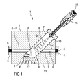
- FIG. 1 shows a dosing unit 1 for dosing a precursor P in a gas stream G.
- the dosing unit 1 comprises a base body 2, which is solid.
- the base body 2 may be formed, for example, from a plastic or a metal, preferably aluminum.
- the base body 2 may be formed substantially parallelepiped or have a different geometric shape.
- a first channel 3 is provided for the gas stream G.
- the first channel 3 comprises a gas inlet 4 and a gas outlet 5, each comprising adapters for connection to pipelines, hoses or other aggregates.
- the gas inlet 4 and the gas outlet 5 each have an internal thread 6 for this purpose. Also external threads, connections with union nuts, Bayonetteuren, clamping and snap connections in the form of compressed air quick couplings or sleeves for attaching hoses and subsequent securing with a hose clamp are possible.
- the first channel 3 may be introduced as a bore in the base body 2.
- the base body 2 has a second channel 7, which lies in a plane with the first channel 3 and this intersects at an angle ⁇ .
- the angle ⁇ is in a range of 0 ° to 90 °, preferably from 0 ° to 60 °, particularly preferably from 30 ° to 45 °, for a compact system structure while maintaining the functional properties of the metering system.
- the second channel 7 can be introduced as a bore in the base body 2.
- the second channel 7 is designed as a blind hole.
- a cleaning opening 9 is introduced as a hole perpendicular to an outer surface 10 of the base body 2 in the base body 2 so that it meets the end of the formed as a blind hole second channel 7.
- the cleaning opening has an internal thread 11 into which a sealing plug 12 can be screwed.
- a Einsprühdüse 14 is arranged, which also includes an adapter for connection to pipes, hoses or other aggregates.
- the adapter of the injection nozzle 14 for this purpose has an internal thread 15. Also external threads, connections with union nuts, Bayonetteuren, clamping and snap connections in the form of compressed air quick couplings or sleeves for attaching hoses and subsequent securing with a hose clamp are possible.
- FIG. 1 shows the dosing unit 1 in a position of use.
- the first channel 3 is flowed through by the gas flow G from the gas inlet 4 in the direction of the gas outlet 5.
- the precursor P for example in liquid form, is injected through the injection nozzle 14 into the second channel 7 in the direction of the crossing point 8, where the precursor P is entrained by the gas stream G, so that thereafter a gas stream G + P acted upon by the precursor P, for example in the form of an aerosol.
- Any heavy particles which may be present in the precursor P and which are not entrained by the gas stream G fall into an end of the second channel 7 which is closed by the stopper 12 in the position of use of the dosing unit 1 below the crossing point 8 and which therefore acts as Particle trap 16 is used. This is easily accessible through the stopper 12 and can therefore be easily cleaned, whereby a quick change between different precursors is possible.
- the precursor P may be an undoped liquid, a liquid having a dissolved solids content, or a liquid (dispersion) charged with particles, for example nanoparticles.
- the precursor may be a silicon-containing precursor, for example an organosilicon precursor, in particular HMDSO, so that a silicate layer is deposited.
- organosilicon precursor in particular HMDSO
- nanoparticles for example, silver or copper may be contained to be deposited in an antibacterial layer.
- the dosing unit 1 can be used as part of a coating apparatus in which the gas stream G + P charged with the precursor is fed to a working gas, an already doped working gas, a plasma formed from the working gas, a fuel gas or a flame formed from the fuel gas, wherein the precursor P is reacted in the plasma or in the flame and reaction products of the precursor P are deposited as particles on a surface of a substrate.
- the coating can be carried out at atmospheric pressure or at low pressure or in a vacuum.
- a plasma inner electrode with the precursor P is avoided, so that it pollutes less quickly. In this way, a high quality of the plasma over substantially longer periods is made possible without a mechanical cleaning of the inner electrode is required.
- the size of the precursor droplets in the aerosol of the gas stream G + P charged with the precursor and, as a result, the size of the deposited ones Particles can be influenced for example by varying process parameters, for example a flow rate of the gas stream G and / or the injection nozzle 14 and / or a distance of the injection nozzle 14 from the crossing point 8 with the gas flow G.
- the metering unit 1 can be supplied with a mixture of precursors P.
- a plurality of metering units can be arranged in series and / or in parallel in one or more gas streams G, each of the metering units 1 being supplied with a different precursor P, each with or without nanoparticles.
- These precursors P may in particular have different states of aggregation and / or be chemically incompatible with one another, which is difficult when they are fed together in one nozzle.
- a silver nitrate solution can be supplied to the gas stream G and then to a plasma burner.
- the layer-forming organosilicon chemical precursor substance (for example HMDSO) can be metered into the gas stream of the plasma burner directly via an upstream evaporator unit or via a series-connected further atomizer unit into the gas stream G + P. Subsequently, a silver-containing silicate layer is deposited on flat textile substrates.
Landscapes
- Chemical & Material Sciences (AREA)
- Engineering & Computer Science (AREA)
- Metallurgy (AREA)
- Chemical Kinetics & Catalysis (AREA)
- Materials Engineering (AREA)
- Mechanical Engineering (AREA)
- General Chemical & Material Sciences (AREA)
- Organic Chemistry (AREA)
- Physics & Mathematics (AREA)
- Plasma & Fusion (AREA)
- Chemical Vapour Deposition (AREA)
- Nozzles (AREA)
- Physical Or Chemical Processes And Apparatus (AREA)
Description
Die Erfindung betrifft eine Dosiereinheit für eine Vorrichtung zur Abscheidung einer Schicht auf einem Substrat und eine Verwendung der Dosiereinheit bei einem Verfahren zur Abscheidung einer Schicht auf einem Substrat.The invention relates to a dosing unit for a device for depositing a layer on a substrate and to a use of the dosing unit in a method for depositing a layer on a substrate.
Um die Oberflächeneigenschaften verschiedener Substrate zu beeinflussen, sind seit geraumer Zeit Beschichtungsverfahren gebräuchlich, bei denen Beschichtungsstoffe aus einer Gasphase auf einer Oberfläche abgeschieden werden. Dabei wird unter anderem zwischen chemischen und physikalischen Gasphasenabscheidungen unterschieden. Bei den chemischen Verfahren werden meist so genannte Precursoren, Vorläuferstoffe der Beschichtungsstoffe, mittels Energiezuführung umgesetzt, Reaktionsprodukte der Precursoren auf die Oberfläche geleitet und dort abgelagert. Die Energiezuführung kann beispielsweise mittels Beflammung erfolgen. Der der Flamme zugeführte Precursor bildet bei seiner thermischen Umsetzung Partikel, insbesondere Nanopartikel, die noch in der Flamme agglomerieren und sich dann an der Oberfläche absetzen. Auf diese Weise ist eine homogene und dichte Beschichtung möglich, jedoch unter hohem Energieeinsatz. Eine andere Möglichkeit bieten so genannte Niederdruckplasmaverfahren, bei denen der Precursor in einer Plasmaquelle oder in deren räumlicher Nähe auf den zu beschichtenden Oberflächen zu Dünnschichten umgesetzt wird.In order to influence the surface properties of various substrates, coating processes have been used for quite some time in which coating materials are deposited from a gas phase on a surface. Among other things, a distinction is made between chemical and physical vapor depositions. In the chemical process, so-called precursors, precursors of the coating materials are usually reacted by means of energy supply, reaction products of the precursors are conducted onto the surface and deposited there. The energy supply can be done for example by means of flame treatment. The precursor supplied to the flame forms particles during its thermal conversion, in particular nanoparticles, which still agglomerate in the flame and then settle on the surface. In this way, a homogeneous and dense coating is possible, but with high energy input. Another possibility is provided by so-called low-pressure plasma processes, in which the precursor is converted into thin layers in a plasma source or in its spatial proximity on the surfaces to be coated.
Seit einigen Jahren sind so genannte Normaldruckplasmaverfahren bekannt, bei denen die zu beschichtenden Oberflächen nicht in ein Vakuum eingebracht werden müssen. Die Partikelbildung erfolgt hierbei schon im Plasma. Die Homogenität der abgeschiedenen Schichten ist, eine geeignete Führung des Substrats vorausgesetzt, mit den durch Beflammung erzielten vergleichbar, der erforderliche thermische Energieeintrag ist jedoch wesentlich geringer.For some years, so-called normal pressure plasma processes are known in which the surfaces to be coated need not be introduced into a vacuum. The particle formation takes place here already in the plasma. The homogeneity of the deposited layers, assuming proper guidance of the substrate, is comparable to that obtained by flame treatment, but the required thermal energy input is much lower.
Aus der
Der Erfindung liegt die Aufgabe zu Grunde, eine verbesserte Dosiereinheit zum Eindosieren eines Precursors in einen Gasstrom und eine Verwendung der Dosiereinheit in einem verbesserten Verfahren zur Abscheidung einer Schicht auf einem Substrat anzugeben.The invention is based on the object of specifying an improved metering unit for metering a precursor into a gas stream and a use of the metering unit in an improved method for depositing a layer on a substrate.
Die Aufgabe wird erfindungsgemäß gelöst durch eine Dosiereinheit mit den Merkmalen des Anspruchs 1 und durch eine Verwendung mit den Merkmalen des Anspruchs 5.The object is achieved by a metering unit with the features of claim 1 and by use with the features of
Vorteilhafte Ausgestaltungen der Erfindung sind Gegenstand der Unteransprüche.Advantageous embodiments of the invention are the subject of the dependent claims.
Eine erfindungsgemäße Dosiereinheit zum Eindosieren eines Precursors in einen Gasstrom umfasst einen Basiskörper mit einem ersten Kanal, der von einem Gaseintritt zu einem Gasaustritt vom Gasstrom durchströmbar ist, und mit einem zweiten Kanal, der den ersten Kanal unter einem Winkel an einem Kreuzungspunkt schneidet, wobei eine Einsprühdüse zum Zuführen des Precursors in den Gasstrom im zweiten Kanal angeordnet ist.A metering unit according to the invention for metering a precursor into a gas stream comprises a base body with a first channel, which is traversed by a gas inlet to a gas outlet from the gas stream, and with a second channel which intersects the first channel at an angle at a crossing point, wherein a Injection nozzle for supplying the precursor is arranged in the gas stream in the second channel.
Erfindungsgemäß ist eine Partikelfalle, die durch ein Ende des zweiten Kanals, das in einer Gebrauchslage der Dosiereinheit unterhalb des Kreuzungspunktes liegt, gebildet wird, vorgesehen.According to the invention, a particle trap is provided which is formed by an end of the second channel, which lies in a position of use of the dosing unit below the point of intersection.
Erfindungsgemäß ist eine mit einem Verschlussstopfen verschließbare Reinigungsöffnung für die Partikelfalle vorgesehen.According to the invention, a closing opening for the particulate trap, which can be closed with a sealing plug, is provided.
Erfindungsgemäß ist der Basiskörper massiv ausgebildet und der erste Kanal als eine Bohrung in den Basiskörper eingebracht.According to the invention, the base body is solid and the first channel is introduced as a bore in the base body.
Der Winkel, unter dem der zweite Kanal den ersten Kanal schneidet, kann beispielsweise in einem Bereich von 30° bis 60°, insbesondere 30° bis 45° liegen. Durch die Wahl des Winkels wird erreicht, dass zum einen genügend Partikel des Precursors im Gasstrom des ersten Kanals mitgenommen werden und zum anderen Partikel oberhalb einer bestimmten Größe in der Partikelfalle verbleiben.The angle at which the second channel intersects the first channel may, for example, be in a range of 30 ° to 60 °, in particular 30 ° to 45 °. The choice of the angle ensures that, on the one hand, sufficient particles of the precursor are entrained in the gas flow of the first channel and, on the other hand, particles above a certain size remain in the particle trap.
Es kann eine Dosieranordnung gebildet werden, umfassend mindestens zwei Dosiereinheiten, wobei die Dosiereinheiten in Reihe in den selben Gasstrom geschaltet sind, sodass dem Gasstrom mehrere Precursoren nacheinander zuführbar sind.A metering arrangement can be formed comprising at least two metering units, wherein the metering units are connected in series in the same gas stream, so that several precursors can be fed to the gas stream in succession.
Ebenso kann eine Dosieranordnung gebildet werden, umfassend mindestens zwei Dosiereinheiten, wobei die Dosiereinheiten parallel geschaltet sind, sodass in jeder der Dosiereinheiten einem jeweiligen Gasstrom jeweils ein Precursor zuführbar ist, wobei die mit dem Precursor beaufschlagten Gasströme zusammengeführt sind.Likewise, a metering arrangement can be formed, comprising at least two metering units, wherein the metering units are connected in parallel, so that in each of the metering units, a respective gas stream each having a precursor can be supplied, wherein the acted upon with the precursor gas streams are brought together.
Ebenso können gemischte Parallel-Reihen-Schaltungen von Dosiereinheiten vorgesehen sein.Likewise, mixed parallel series circuits of metering units may be provided.
Bei einer erfindungsgemäßen Verwendung der Dosiereinheit in einem Verfahren zur Abscheidung einer Schicht auf einem Substrat wird aus einem Arbeitsgas ein Plasmastrahl oder eine Flamme erzeugt, wobei mindestens ein Precursor mindestens einem Gasstrom in einer Dosiereinheit oder einer Dosieranordnung zugeführt und der mit dem Precursor beaufschlagte Gasstrom dem Arbeitsgas und/oder dem Plasmastrahl und/oder der Flamme zugeführt und der Precursor im Plasmastrahl oder der Flamme zur Reaktion gebracht wird, wobei mindestens ein Reaktionsprodukt mindestens eines der Precursoren auf einer Oberfläche des Substrats und/oder auf mindestens einer auf der Oberfläche angeordneten Schicht abgeschieden wird.In a use according to the invention of the dosing unit in a method for depositing a layer on a substrate, a plasma jet or a flame is generated from a working gas, wherein at least one precursor is supplied to at least one gas stream in a dosing unit or a dosing arrangement and the gas stream charged with the precursor is supplied to the working gas and / or the plasma jet and / or the flame, and the precursor is reacted in the plasma jet or the flame, wherein at least one reaction product of at least one of the precursors is deposited on a surface of the substrate and / or on at least one layer disposed on the surface ,
Der Precursor P kann eine undotierte Flüssigkeit sein. Erfindungsgemäß ist der Precursor eine Flüssigkeit mit gelöstem Feststoffanteil oder eine mit Partikeln, beispielsweise Nanopartikeln, beaufschlagte Flüssigkeit (Dispersion). Im Precursor vorhandene schwere Partikel, die vom Gasstrom im ersten Kanal nicht mitgenommen werden, fallen erfindungsgemäß in die durch das in Gebrauchslage der Dosiereinheit unterhalb des Kreuzungspunktes liegende, durch den Verschlussstopfen verschlossene, als Partikelfalle dienende, Ende des zweiten Kanals.The precursor P may be an undoped liquid. According to the invention, the precursor is a liquid having a dissolved solids content or a liquid (dispersion) charged with particles, for example nanoparticles. According to the invention, heavy particles present in the precursor, which are not carried along by the gas stream in the first channel, fall into the end of the second channel which is located below the point of intersection in the position of use of the dosing unit and closed by the sealing plug, serving as a particle trap.
Als Nanopartikel wird in diesem Zusammenhang ein Verbund von Atomen und/oder Molekülen verstanden, dessen Größe typischerweise in einem Bereich von einem bis einigen hundert Nanometern liegt. Nanopartikel weisen gegenüber größeren Partikeln bzw. Festkörpern deutlich veränderte Eigenschaften beispielsweise in Bezug auf chemische Reaktivität, tribologische Eigenschaften oder elektrische Leitfähigkeit auf. Eine Verwendung dieser Nanopartikel im Bereich der Beschichtungstechnologie eröffnet neue Möglichkeiten der Oberflächenmodifikation.In this context, nanoparticles are understood as meaning a composite of atoms and / or molecules whose size is typically in the range from one to a few hundred nanometers. Nanoparticles have, compared with larger particles or solids, significantly changed properties, for example with regard to chemical reactivity, tribological properties or electrical conductivity. Use of these nanoparticles in the field of coating technology opens up new possibilities for surface modification.
Die erfindungsgemäße Dosiereinheit und die erfindungsgemäße Verwendung bei einem Verfahren zum Beschichten ermöglichen die Eindosierung des Precursors in Gasströme mit geringem Durchsatz, wobei eine Beschränkung der Größe der abgeschiedenen Partikel durch Variation von Verfahrensparametern möglich ist. Als Precursor werden beispielsweise silizium-, titan- und/oder aluminiumorganische Verbindungen verwendet. Es kann eine Vielzahl schichtbildender und Nanopartikel bildender Precursoren, beispielsweise Hexamethyldisiloxan (HMDSO), Titantetraisopropoxid (TTIP), Tetraethylorthosilikat (TEOS), Tetramethylorthosilikat (TMOS), ZnNO3-, AgNO3-Lösungen und andere Lösungen von Kationen, sowie Nanopartikel Dispersionen aus Metallen (Ag, Au, Ca, Cu) und/oder Metallverbindungen (ZnO, CoO) und/oder Nichtmetallverbindungen (Bornitrid, Kohlenstoff-Nanotubes) verwendet werden.The dosing unit according to the invention and the use according to the invention in a coating method enable the precursor to be metered into gas streams at a low throughput, wherein it is possible to limit the size of the separated particles by varying process parameters. As precursor, for example, silicon, titanium and / or organoaluminum compounds are used. It can be a variety of layer-forming and nanoparticle-forming precursors, such as hexamethyldisiloxane (HMDSO), titanium tetraisopropoxide (TTIP), tetraethyl orthosilicate (TEOS), tetramethyl orthosilicate (TMOS), ZnNO 3 -, AgNO 3 solutions and other solutions of cations, as well as nanoparticle dispersions of metals (Ag, Au, Ca, Cu) and / or metal compounds (ZnO, CoO) and / or non-metal compounds (boron nitride, carbon nanotubes) can be used.
Bei der erfindungsgemäßen Verwendung wird die Dosiereinheit als Teil einer Beschichtungsvorrichtung verwendet, in der der mit dem Precursor beaufschlagte Gasstrom einem Arbeitsgas, einem bereits dotierten Arbeitsgas, einem aus dem Arbeitsgas gebildeten Plasma, einem Brenngas oder einer aus dem Brenngas gebildeten Flamme zugeführt wird, wobei der Precursor im Plasma oder in der Flamme umgesetzt und Reaktionsprodukte des Precursors als Partikel auf einer Oberfläche eines Substrats abgeschieden werden. Die Beschichtung kann bei Atmosphärendruck oder bei Niederdruck oder im Vakuum durchgeführt werden.In the use according to the invention, the dosing unit is used as part of a coating apparatus in which the gas stream charged with the precursor is fed to a working gas, an already doped working gas, a plasma formed from the working gas, a fuel gas or a flame formed from the fuel gas, wherein the Precursor reacted in the plasma or in the flame and reaction products of the precursor are deposited as particles on a surface of a substrate. The coating can be carried out at atmospheric pressure or at low pressure or in a vacuum.
Das Verfahren wird bevorzugt bei Atmosphärendruck durchgeführt, wodurch auf besonders vorteilhafte Weise ein zeitaufwändiger Prozessschritt des Evakuierens einer Prozesskammer sowie Apparaturen zur Vakuumerzeugung, wie Vakuumpumpen und Prozesskammer, eingespart wird. Dadurch lässt sich das Verfahren ohne großen Aufwand in eine Prozesskette integrieren, die eine Herstellung und Vergütung des Substrats beinhaltet.The method is preferably carried out at atmospheric pressure, which saves in a particularly advantageous manner, a time-consuming process step of evacuating a process chamber and apparatus for vacuum generation, such as vacuum pumps and process chamber. As a result, the method can be integrated into a process chain without great effort, which involves production and compensation of the substrate.
Insbesondere bei Verwendung eines Plasmas wird durch die Eindosierung des Precursors in der Dosiereinheit entfernt vom Plasmabrenner ein Ansprühen einer Plasmainnenelektrode mit dem Precursor vermieden, sodass diese weniger schnell verschmutzt. Auf diese Weise wird eine hohe Qualität des Plasmas über wesentlich längere Zeiträume ermöglicht, ohne dass eine mechanische Reinigung der Innenelektrode erforderlich wird. Ebenso werden Durchbrüche zwischen den Plasmaelektroden vermieden, bei denen anderenfalls Elektrodenmaterial in den Plasmastrom gelangen und die zu beschichtende Oberfläche verunreinigen kann.In particular, when using a plasma by spraying the Precursors in the dosing unit away from the plasma torch a spraying of a plasma inner electrode is avoided with the precursor so that it pollutes less quickly. In this way, a high quality of the plasma over substantially longer periods is made possible without a mechanical cleaning of the inner electrode is required. Similarly, breakthroughs between the plasma electrodes are avoided in which otherwise electrode material can enter the plasma stream and contaminate the surface to be coated.
Als Arbeitsgas und im Gasstrom in der Dosiereinheit kann ein Gas oder Aerosol, vorzugsweise Luft, Sauerstoff, Stickstoff, Edelgase, Wasserstoff, Kohlendioxid, gasförmige Kohlenwasserstoffe, Ammoniak oder ein Gemisch wenigstens zweier der vorgenannten Gase verwendet werden. Ammoniak eignet sich beispielsweise zur Bildung von Nitriden und kann eine katalytische Wirkung bei der Umsetzung des Precursors aufweisen.As the working gas and in the gas stream in the metering unit, a gas or aerosol, preferably air, oxygen, nitrogen, noble gases, hydrogen, carbon dioxide, gaseous hydrocarbons, ammonia or a mixture of at least two of the aforementioned gases can be used. Ammonia, for example, is suitable for the formation of nitrides and may have a catalytic effect in the reaction of the precursor.
In einer Ausgestaltung der Erfindung wird mindestens eine Gradientenschicht abgeschieden. Als Gradientenschicht soll eine Schicht verstanden werden, deren Zusammensetzung sich über ihre Dicke allmählich ändert. Der Begriff wird in Abgrenzung zu benachbarten Schichten mit verschiedenen Eigenschaften verwendet, die eine klare Grenze aufweisen.In one embodiment of the invention, at least one gradient layer is deposited. The gradient layer is to be understood as meaning a layer whose composition changes gradually over its thickness. The term is used in contrast to adjacent layers with different properties that have a clear boundary.
Es kann mindestens eine Silizium-, Titan- und/oder Aluminiumoxidschicht abgeschieden werden.At least one silicon, titanium and / or aluminum oxide layer can be deposited.
Eine vorteilhafte Ausgestaltung der Erfindung sieht vor, dass ein Durchsatz des Arbeitsgases und/oder des Precursors gesteuert und/oder geregelt wird.An advantageous embodiment of the invention provides that a throughput of the working gas and / or the precursor is controlled and / or regulated.
Weiterhin kann ein Nanopartikelanteil im Precursor und/oder in der Dispersion gesteuert und/oder geregelt werden. Neben dem Durchsatz des Arbeitsgases und/oder des Precursors steht somit eine weitere Möglichkeit zur Beeinflussung der Schichteigenschaften bzw. zum Aufbau von Gradienten innerhalb einer Schicht zur Verfügung. Durch geeignete Wahl dieser Prozessparameter und der verwendeten Precursoren und der verwendeten Nanopartikel sind beispielsweise folgende Eigenschaften des Substrats gezielt veränderbar: Kratzfestigkeit, Selbstheilungsfähigkeit, Reflexionsverhalten, Transmissionsverhalten, Fluoreszenzverhalten, Brechungsindex, Transparenz, Lichtstreuung, elektrische Leitfähigkeit, Reibung, Haftung, Hydrophilie, Hydrophobie, Oleophilie, Oleophobie, Oberflächenspannung, Oberflächenenergie, antikorrosive Wirkung, Schmutz abweisende Wirkung, Selbstreinigungsfähigkeit, photokatalytisches Verhalten, Antistressverhalten, Verschleißverhalten, chemische Widerstandsfähigkeit, biozides Verhalten, biokompatibles Verhalten, antibakterielles Verhalten, elektrostatisches Verhalten, elektrochrome Aktivität, photochrome Aktivität, und gasochrome Aktivität.Furthermore, a nanoparticle content in the precursor and / or in the dispersion can be controlled and / or regulated. In addition to the throughput of the working gas and / or the precursor, there is thus another possibility for influencing the layer properties or for establishing gradients within a layer. By suitable choice of these process parameters and the precursors and nanoparticles used, for example, the following properties of the substrate can be selectively changed: scratch resistance, self-healing ability, reflection behavior, transmission behavior, fluorescence behavior, refractive index, transparency, light scattering, electrical conductivity, friction, adhesion, hydrophilicity, hydrophobicity, oleophilicity , Oleophobicity, surface tension, surface energy, anti-corrosive effect, dirt repellent effect, self-cleaning ability, photocatalytic behavior, anti-stress behavior, wear behavior, chemical resistance, biocidal behavior, biocompatible behavior, antibacterial behavior, electrostatic behavior, electrochromic activity, photochromic activity, and gasochromic activity.
Als Substrate können unter anderem Metalle, Glas, Keramiken und Kunststoffe verwendet werden. Kunststoffmaterialien sind insbesondere aufgrund des moderaten Energieeintrags des Normaldruckplasmas beschichtbar, ohne dass das Substrat zerstört wird.Metals, glass, ceramics and plastics can be used as substrates, among others. Plastic materials are particularly due to the moderate energy input of the normal pressure plasma coatable without the substrate is destroyed.
Ausführungsbeispiele der Erfindung werden im Folgenden anhand einer Zeichnung näher erläutert.Embodiments of the invention will be explained in more detail below with reference to a drawing.
Darin zeigen:
- Figur 1
- eine Dosiereinheit zum Eindosieren eines Precursors in einen Gasstrom.
- FIG. 1
- a dosing unit for dosing a precursor into a gas stream.
Im Basiskörper 2 ist ein erster Kanal 3 für den Gasstrom G vorgesehen. Der erste Kanal 3 umfasst einen Gaseintritt 4 und einen Gasaustritt 5, die jeweils Adapter zum Verbinden mit Rohrleitungen, Schläuchen oder anderen Aggregaten umfassen. Im gezeigten Beispiel weisen der Gaseintritt 4 und der Gasaustritt 5 hierfür jeweils ein Innengewinde 6 auf. Ebenso sind Außengewinde, Verbindungen mit Überwurfmuttern, Bayonettverbindungen, Klemm- und Schnappverbindungen in der Art von Druckluft-Schnellkupplungen oder Hülsen zum Aufstecken von Schläuchen und anschließendem Sichern mit einer Schlauchschelle möglich.In the
Der erste Kanal 3 kann als eine Bohrung in den Basiskörper 2 eingebracht sein.The
Der Basiskörper 2 weist einen zweiten Kanal 7 auf, der in einer Ebene mit dem ersten Kanal 3 liegt und diesen unter einem Winkel α schneidet. Der Winkel α liegt in einem Bereich von 0° bis 90°, bevorzugt von 0° bis 60°, besonders bevorzugt von 30° bis 45°, für einen kompakten Systemaufbau unter Beibehaltung der funktionellen Eigenschaften des Dosiersystems.The
Der zweite Kanal 7 kann als eine Bohrung in den Basiskörper 2 eingebracht sein. Im dargestellten Beispiel ist der zweite Kanal 7 als ein Sackloch ausgeführt. Das nach einem Kreuzungspunkt 8 mit dem ersten Kanal 3 endet. Eine Reinigungsöffnung 9 ist als Bohrung rechtwinklig zu einer Außenfläche 10 des Basiskörpers 2 so in den Basiskörper 2 eingebracht, dass sie auf das Ende des als Sackloch ausgebildeten zweiten Kanals 7 trifft. Die Reinigungsöffnung weist ein Innengewinde 11 auf, in das ein Verschlussstopfen 12 einschraubbar ist.The
An einem Eingang 13 des zweiten Kanals 3 ist eine Einsprühdüse 14 angeordnet, die ebenfalls ein Adapter zum Verbinden mit Rohrleitungen, Schläuchen oder anderen Aggregaten umfasst. Im gezeigten Beispiel weist der Adapter der Einsprühdüse 14 hierfür ein Innengewinde 15 auf. Ebenso sind Außengewinde, Verbindungen mit Überwurfmuttern, Bayonettverbindungen, Klemm- und Schnappverbindungen in der Art von Druckluft-Schnellkupplungen oder Hülsen zum Aufstecken von Schläuchen und anschließendem Sichern mit einer Schlauchschelle möglich.At an
Durch die Einsprühdüse 14 wird der Precursor P, beispielsweise in flüssiger Form, in den zweiten Kanal 7 in Richtung des Kreuzungspunktes 8 eingedüst, wo der Precursor P vom Gasstrom G mitgerissen wird, sodass danach ein mit dem Precursor P beaufschlagter Gasstrom G+P, beispielsweise in Form eines Aerosols vorliegt. Eventuell im Precursor P vorhandene schwere Partikel, die vom Gasstrom G nicht mitgenommen werden, fallen in eine durch das in Gebrauchslage der Dosiereinheit 1 unterhalb des Kreuzungspunktes 8 liegende, durch den Verschlussstopfen 12 verschlossene Ende des zweiten Kanals 7, das daher als Partikelfalle 16 dient. Diese ist durch den Verschlussstopfen 12 leicht zugänglich und kann daher einfach gereinigt werden, wodurch ein schneller Wechsel zwischen verschiedenen Precursoren möglich ist.The precursor P, for example in liquid form, is injected through the
Der Precursor P kann eine undotierte Flüssigkeit, eine Flüssigkeit mit gelöstem Feststoffanteil oder eine mit Partikeln, beispielsweise Nanopartikeln, beaufschlagte Flüssigkeit (Dispersion) sein.The precursor P may be an undoped liquid, a liquid having a dissolved solids content, or a liquid (dispersion) charged with particles, for example nanoparticles.
Der Precursor kann ein siliziumhaltiger Precursor, beispielsweise ein siliziumorganischer Precursor, insbesondere HMDSO sein, sodass eine Silikatschicht abgeschieden wird.The precursor may be a silicon-containing precursor, for example an organosilicon precursor, in particular HMDSO, so that a silicate layer is deposited.
Als Nanopartikel können beispielsweise Silber oder Kupfer enthalten sein, um in einer antibakteriellen Schicht abgeschieden zu werden.As nanoparticles, for example, silver or copper may be contained to be deposited in an antibacterial layer.
Die Dosiereinheit 1 kann als Teil einer Beschichtungsvorrichtung verwendet werden, in der der mit dem Precursor beaufschlagte Gasstrom G+P einem Arbeitsgas, einem bereits dotierten Arbeitsgas, einem aus dem Arbeitsgas gebildeten Plasma, einem Brenngas oder einer aus dem Brenngas gebildeten Flamme zugeführt wird, wobei der Precursor P im Plasma oder in der Flamme umgesetzt und Reaktionsprodukte des Precursors P als Partikel auf einer Oberfläche eines Substrats abgeschieden werden. Die Beschichtung kann bei Atmosphärendruck oder bei Niederdruck oder im Vakuum durchgeführt werden. Insbesondere bei Verwendung eines Plasmas wird durch die Eindosierung des Precursors P in der Dosiereinheit 1 statt in einen Plasmabrenner ein Ansprühen einer Plasmainnenelektrode mit dem Precursor P vermieden, sodass diese weniger schnell verschmutzt. Auf diese Weise wird eine hohe Qualität des Plasmas über wesentlich längere Zeiträume ermöglicht, ohne dass eine mechanische Reinigung der Innenelektrode erforderlich wird.The dosing unit 1 can be used as part of a coating apparatus in which the gas stream G + P charged with the precursor is fed to a working gas, an already doped working gas, a plasma formed from the working gas, a fuel gas or a flame formed from the fuel gas, wherein the precursor P is reacted in the plasma or in the flame and reaction products of the precursor P are deposited as particles on a surface of a substrate. The coating can be carried out at atmospheric pressure or at low pressure or in a vacuum. In particular, when using a plasma by spraying the precursor P in the dosing unit 1 instead of a plasma torch, a spraying of a plasma inner electrode with the precursor P is avoided, so that it pollutes less quickly. In this way, a high quality of the plasma over substantially longer periods is made possible without a mechanical cleaning of the inner electrode is required.
Die Größe der Precursortröpfchen im Aerosol des mit dem Precursor beaufschlagten Gasstroms G+P und infolgedessen die Größe der abgeschiedenen Partikel kann beispielsweise durch Variation von Verfahrensparametern, beispielsweise einer Durchflussmenge des Gasstroms G und/oder der Einsprühdüse 14 und/oder einer Distanz der Einsprühdüse 14 vom Kreuzungspunkt 8 mit dem Gasstrom G beeinflusst werden.The size of the precursor droplets in the aerosol of the gas stream G + P charged with the precursor and, as a result, the size of the deposited ones Particles can be influenced for example by varying process parameters, for example a flow rate of the gas stream G and / or the
Der Dosiereinheit 1 kann ein Gemisch von Precursoren P zugeführt werden. Ebenso können mehrere Dosiereinheiten in Reihe und/oder parallel in einem oder mehreren Gasströmen G angeordnet sein, wobei jeder der Dosiereinheiten 1 ein anderer Precursor P jeweils mit oder ohne Nanopartikel zugeführt wird. Diese Precursoren P können insbesondere verschiedene Aggregatzustände aufweisen und/oder untereinander chemisch unverträglich sein, was bei gemeinsamer Zuführung in einer Düse schwierig ist.The metering unit 1 can be supplied with a mixture of precursors P. Likewise, a plurality of metering units can be arranged in series and / or in parallel in one or more gas streams G, each of the metering units 1 being supplied with a different precursor P, each with or without nanoparticles. These precursors P may in particular have different states of aggregation and / or be chemically incompatible with one another, which is difficult when they are fed together in one nozzle.
Beispielsweise kann als Precursor P eine Silbernitratlösung dem Gasstrom G und anschließend einem Plasmabrenner zugeführt werden. Die schichtbildende siliziumorganische chemische Vorläufersubstanz (bspw. HMDSO) kann zum einen dem Arbeitsgasstrom des Plasmabrenners direkt über eine vorgeschaltete Verdampfereinheit oder über eine in Reihe geschaltete weitere Zerstäubereinheit in den Gasstrom G+P eindosiert werden. Anschließend wird eine silberhaltige Silikatschicht auf flächigen Textilsubstraten abgeschieden.For example, as a precursor P, a silver nitrate solution can be supplied to the gas stream G and then to a plasma burner. The layer-forming organosilicon chemical precursor substance (for example HMDSO) can be metered into the gas stream of the plasma burner directly via an upstream evaporator unit or via a series-connected further atomizer unit into the gas stream G + P. Subsequently, a silver-containing silicate layer is deposited on flat textile substrates.
- 11
- Dosiereinheitdosing
- 22
- Basiskörperbase body
- 33
- erster Kanalfirst channel
- 44
- Gaseintrittgas inlet
- 55
- Gasaustrittgas outlet
- 66
- Innengewindeinner thread
- 77
- zweiter Kanalsecond channel
- 88th
- Kreuzungspunktintersection
- 99
- Reinigungsöffnungcleaning opening
- 1010
- Außenflächeouter surface
- 1111
- Innengewindeinner thread
- 1212
- Verschlusstopfensealing plug
- 1313
- Eingangentrance
- 1414
- Einsprühdüsespray nozzle
- 1515
- Innengewindeinner thread
- 1616
- Partikelfalleparticulate trap
- αα
- Winkelangle
- GG
- Gasstromgas flow
- G+PG + P
- mit dem Precursor beaufschlagter Gasstromwith the precursor acted upon gas stream
- PP
- Precursorprecursor
Claims (10)
- Dosing unit (1) for dosing a precursor (P) into a gas stream (G), comprising a main body (2) which is of solid form and which has a first duct (3), through which the gas stream can flow from a gas inlet (4) to a gas outlet (5) and which is formed as a bore into the main body (2), and a second duct (7), which intersects the first duct (3) at an angle (α) at a crossing point (8), wherein an injection nozzle (14) for feeding the precursor (P) into the gas stream (G) is arranged in the second duct (7), wherein, below the crossing point (8) in a usage position of the dosing unit (1), one end of the second duct is in the form of a particle trap (16), wherein a cleaning opening (9), which can be closed off by way of a closure plug (12), is provided for the particle trap (16).
- Dosing unit according to Claim 1, characterized in that the angle (α) lies in a range from 30° to 45°.
- Dosing arrangement, comprising at least two dosing units (1) according to one of the preceding claims, wherein the dosing units (1) are positioned in series in the same gas stream (G), such that multiple precursors (P) can be fed to the gas stream (G) in succession.
- Dosing arrangement, comprising at least two dosing units (1) according to one of the preceding claims, wherein the dosing units (1) are positioned in parallel such that, in each of the dosing units (1), a respective precursor (P) can be fed to a respective gas stream (G), wherein the gas streams (G+P) that have had the precursor (P) added to them are merged.
- Use of at least one dosing unit (1) according to either of Claims 1 and 2 in a method for depositing a layer on a substrate, in which method a plasma jet or a flame is generated from a working gas, wherein the first duct (3) which is formed as a bore in the main body (2), of solid form, of the dosing unit (1) is flowed through from the gas inlet (4) to the gas outlet (5) by a gas stream (G), wherein the second duct (7), which intersects the first duct (3) at an angle (α) at the intersection point (8), has a precursor (P), which is in the form of a liquid with a dissolved solids fraction or as a liquid containing particles, fed to it by the injection nozzle (14) in the direction of the crossing point (8), where the precursor (P) is entrained by the gas stream (G), wherein heavy particles which are present in the precursor (P) and which are not entrained by the gas stream (G) fall into that end of the second duct (7) which, in the usage position of the dosing unit (1), is situated below the crossing point (8) and which is closed off by the closure plug (12) and which serves as a particle trap (16), wherein the gas stream (G+P) that has had the precursor (P) added to it is fed to the working gas and/or to the plasma jet and/or to the flame, and the precursor (P) is caused to react in the plasma jet or the flame, wherein at least one reaction product of at least one of the precursors (P) is deposited on a surface of the substrate.
- Use according to Claim 5, wherein at least two dosing units (1) are, to form a dosing arrangement, positioned in series in the same gas stream (G), such that multiple precursors (P) are fed to the gas stream (G) in succession.
- Use according to Claim 5 or 6, wherein at least two dosing units (1) are, to form a dosing arrangement, positioned in parallel, such that, in each of the dosing units (1), a respective precursor (P) is fed to a respective gas stream (G), wherein the gas streams (G+P) that have had the precursor (P) added to them are merged.
- Use according to one of Claims 5 to 7, characterized in that the precursor (P) comprises nanoparticles.
- Use according to Claim 8, characterized in that the nanoparticles comprise silver and/or copper.
- Use according to one of Claims 5 to 8, characterized in that the deposition is performed at atmospheric pressure.
Applications Claiming Priority (1)
| Application Number | Priority Date | Filing Date | Title |
|---|---|---|---|
| DE201210220986 DE102012220986B4 (en) | 2012-11-16 | 2012-11-16 | Dosing unit and its use |
Publications (2)
| Publication Number | Publication Date |
|---|---|
| EP2743373A1 EP2743373A1 (en) | 2014-06-18 |
| EP2743373B1 true EP2743373B1 (en) | 2015-06-24 |
Family
ID=49582640
Family Applications (1)
| Application Number | Title | Priority Date | Filing Date |
|---|---|---|---|
| EP13192939.0A Active EP2743373B1 (en) | 2012-11-16 | 2013-11-14 | Metering unit and use of the same |
Country Status (3)
| Country | Link |
|---|---|
| EP (1) | EP2743373B1 (en) |
| DE (1) | DE102012220986B4 (en) |
| DK (1) | DK2743373T3 (en) |
Cited By (4)
| Publication number | Priority date | Publication date | Assignee | Title |
|---|---|---|---|---|
| DE102017216139B3 (en) | 2017-09-13 | 2019-02-28 | Innovent E.V. | Process for producing a layer |
| EP3680361A1 (en) | 2019-01-09 | 2020-07-15 | Innovent e.V. | Attachment for dosing a precursor and method for producing a layer |
| EP4063016A1 (en) | 2021-03-25 | 2022-09-28 | Verein zur Förderung von Innovationen durch Forschung, Entwicklung und Technologietransfer e.V. (Verein INNOVENT e.V.) | Atomizing nozzle |
| DE102023104084A1 (en) | 2023-02-20 | 2024-08-22 | Verein zur Förderung von Innovationen durch Forschung, Entwicklung und Technologietransfer e.V. (Verein INNOVENT e.V.) | Dosing unit and its use |
Families Citing this family (2)
| Publication number | Priority date | Publication date | Assignee | Title |
|---|---|---|---|---|
| DE102016104130A1 (en) * | 2016-03-07 | 2017-09-07 | Plasmatreat Gmbh | Method for coating a component surface and method for producing a coating material |
| DE102016104128A1 (en) * | 2016-03-07 | 2017-09-07 | Plasmatreat Gmbh | Method for coating a component surface, coated component and use of a precursor material |
Family Cites Families (14)
| Publication number | Priority date | Publication date | Assignee | Title |
|---|---|---|---|---|
| US6195504B1 (en) * | 1996-11-20 | 2001-02-27 | Ebara Corporation | Liquid feed vaporization system and gas injection device |
| DE19958473A1 (en) | 1999-12-04 | 2001-06-07 | Bosch Gmbh Robert | Process for the production of composite layers with a plasma beam source |
| DE19958474A1 (en) | 1999-12-04 | 2001-06-21 | Bosch Gmbh Robert | Process for producing functional layers with a plasma beam source |
| EP1301341B1 (en) | 2000-06-30 | 2006-08-23 | nGimat Co. | Method for applying polymer coatings |
| FR2829707B1 (en) * | 2001-09-19 | 2003-12-12 | Air Liquide | METHOD AND DEVICE FOR MIXING TWO REACTIVE GASES |
| JP2003268552A (en) * | 2002-03-18 | 2003-09-25 | Watanabe Shoko:Kk | Vaporizer and various kinds of apparatus using the same, and vaporization method |
| GB0211354D0 (en) * | 2002-05-17 | 2002-06-26 | Surface Innovations Ltd | Atomisation of a precursor into an excitation medium for coating a remote substrate |
| DE10239875B4 (en) * | 2002-08-29 | 2008-11-06 | Fraunhofer-Gesellschaft zur Förderung der angewandten Forschung e.V. | Method and device for the large-area coating of substrates under atmospheric pressure conditions |
| US20070194470A1 (en) * | 2006-02-17 | 2007-08-23 | Aviza Technology, Inc. | Direct liquid injector device |
| US20080003425A1 (en) * | 2006-06-29 | 2008-01-03 | Spencer James T | Systems and Methods of the Formation of Solid State Metal Boride and Oxide Coatings |
| EP2190263B1 (en) * | 2007-09-10 | 2013-03-20 | Ulvac, Inc. | Process for producing thin organic film |
| CN101803460B (en) * | 2007-09-10 | 2012-01-25 | 株式会社爱发科 | Organic-material vapor generator, film deposition source, and film deposition apparatus |
| CN101803462B (en) * | 2007-09-10 | 2012-06-27 | 株式会社爱发科 | Vapor emission device, organic thin-film vapor deposition apparatus and method of organic thin-film vapor deposition |
| DE102008033938B4 (en) * | 2008-07-18 | 2012-04-19 | Innovent E.V. | Method for depositing layers on a substrate |
-
2012
- 2012-11-16 DE DE201210220986 patent/DE102012220986B4/en not_active Expired - Fee Related
-
2013
- 2013-11-14 EP EP13192939.0A patent/EP2743373B1/en active Active
- 2013-11-14 DK DK13192939.0T patent/DK2743373T3/en active
Cited By (5)
| Publication number | Priority date | Publication date | Assignee | Title |
|---|---|---|---|---|
| DE102017216139B3 (en) | 2017-09-13 | 2019-02-28 | Innovent E.V. | Process for producing a layer |
| EP3680361A1 (en) | 2019-01-09 | 2020-07-15 | Innovent e.V. | Attachment for dosing a precursor and method for producing a layer |
| EP4063016A1 (en) | 2021-03-25 | 2022-09-28 | Verein zur Förderung von Innovationen durch Forschung, Entwicklung und Technologietransfer e.V. (Verein INNOVENT e.V.) | Atomizing nozzle |
| DE102021107482A1 (en) | 2021-03-25 | 2022-09-29 | Verein zur Förderung von Innovationen durch Forschung, Entwicklung und Technologietransfer e.V. (Verein INNOVENT e.V.) | atomizer nozzle |
| DE102023104084A1 (en) | 2023-02-20 | 2024-08-22 | Verein zur Förderung von Innovationen durch Forschung, Entwicklung und Technologietransfer e.V. (Verein INNOVENT e.V.) | Dosing unit and its use |
Also Published As
| Publication number | Publication date |
|---|---|
| DE102012220986B4 (en) | 2015-04-02 |
| DE102012220986A1 (en) | 2014-05-22 |
| DK2743373T3 (en) | 2015-09-14 |
| EP2743373A1 (en) | 2014-06-18 |
Similar Documents
| Publication | Publication Date | Title |
|---|---|---|
| EP2743373B1 (en) | Metering unit and use of the same | |
| EP2194162A2 (en) | Use of a coating | |
| DE69800158T2 (en) | Device and method for heat treatment | |
| EP2836439B1 (en) | Coating containers using plasma nozzles | |
| DE102010062357B4 (en) | Apparatus and method for producing a magnesium-containing substrate coated with at least one anticorrosion layer | |
| DE102008029681A1 (en) | Method and device for applying a layer, in particular a self-cleaning and / or antimicrobial photocatalytic layer, to a surface | |
| DE102009048397A1 (en) | Atmospheric pressure plasma process for producing surface modified particles and coatings | |
| EP3094761B1 (en) | Plasma coating method for depositing a functional layer, and depositing device | |
| WO2001061071B1 (en) | Condensation coating method | |
| EP2145977B1 (en) | Method for depositing layers on a substrate | |
| WO2011020851A1 (en) | Coatings filled with particles, production method and uses thereof | |
| EP1417042B1 (en) | Method for producing a coated synthetic body | |
| DE102008033941A1 (en) | Method for coating | |
| DE102017216139B3 (en) | Process for producing a layer | |
| EP4063016A1 (en) | Atomizing nozzle | |
| EP2682501B1 (en) | Plasma coating apparatus and method for plasma coating a substrate | |
| DE10012516C1 (en) | Component with a transparent scratch-resistant protective gradient layer consisting of silicon, oxygen, hydrocarbon residues and a metal whose oxides absorb UV light | |
| EP2304076B1 (en) | Process for the internal coating of hollow bodies using a plasma beam at atmospheric pressure | |
| WO1996025243A1 (en) | Process for producing a layer system on substrates and the layer system produced by the said method | |
| DE102009000259A1 (en) | Method for modifying the surface of particles and device suitable therefor | |
| DE102010043949B4 (en) | Apparatus and method for coating surfaces | |
| DE102016104130A1 (en) | Method for coating a component surface and method for producing a coating material | |
| EP2631332A1 (en) | Method for metalizing a substrate | |
| DE102009037371B3 (en) | Coating device for substrate, comprises atomizing chamber, in which coating solution or coating dispersion is converted into aerosol by series of ultrasound sources having ultrasonic atomizer | |
| DE102023104084A1 (en) | Dosing unit and its use |
Legal Events
| Date | Code | Title | Description |
|---|---|---|---|
| PUAI | Public reference made under article 153(3) epc to a published international application that has entered the european phase |
Free format text: ORIGINAL CODE: 0009012 |
|
| 17P | Request for examination filed |
Effective date: 20131114 |
|
| AK | Designated contracting states |
Kind code of ref document: A1 Designated state(s): AL AT BE BG CH CY CZ DE DK EE ES FI FR GB GR HR HU IE IS IT LI LT LU LV MC MK MT NL NO PL PT RO RS SE SI SK SM TR |
|
| AX | Request for extension of the european patent |
Extension state: BA ME |
|
| R17P | Request for examination filed (corrected) |
Effective date: 20141006 |
|
| RBV | Designated contracting states (corrected) |
Designated state(s): AL AT BE BG CH CY CZ DE DK EE ES FI FR GB GR HR HU IE IS IT LI LT LU LV MC MK MT NL NO PL PT RO RS SE SI SK SM TR |
|
| GRAP | Despatch of communication of intention to grant a patent |
Free format text: ORIGINAL CODE: EPIDOSNIGR1 |
|
| INTG | Intention to grant announced |
Effective date: 20150305 |
|
| GRAS | Grant fee paid |
Free format text: ORIGINAL CODE: EPIDOSNIGR3 |
|
| GRAA | (expected) grant |
Free format text: ORIGINAL CODE: 0009210 |
|
| AK | Designated contracting states |
Kind code of ref document: B1 Designated state(s): AL AT BE BG CH CY CZ DE DK EE ES FI FR GB GR HR HU IE IS IT LI LT LU LV MC MK MT NL NO PL PT RO RS SE SI SK SM TR |
|
| REG | Reference to a national code |
Ref country code: GB Ref legal event code: FG4D Free format text: NOT ENGLISH |
|
| REG | Reference to a national code |
Ref country code: CH Ref legal event code: EP |
|
| REG | Reference to a national code |
Ref country code: AT Ref legal event code: REF Ref document number: 732923 Country of ref document: AT Kind code of ref document: T Effective date: 20150715 |
|
| REG | Reference to a national code |
Ref country code: IE Ref legal event code: FG4D Free format text: LANGUAGE OF EP DOCUMENT: GERMAN |
|
| REG | Reference to a national code |
Ref country code: DE Ref legal event code: R096 Ref document number: 502013000779 Country of ref document: DE |
|
| REG | Reference to a national code |
Ref country code: DK Ref legal event code: T3 Effective date: 20150908 |
|
| PG25 | Lapsed in a contracting state [announced via postgrant information from national office to epo] |
Ref country code: FI Free format text: LAPSE BECAUSE OF FAILURE TO SUBMIT A TRANSLATION OF THE DESCRIPTION OR TO PAY THE FEE WITHIN THE PRESCRIBED TIME-LIMIT Effective date: 20150624 Ref country code: NO Free format text: LAPSE BECAUSE OF FAILURE TO SUBMIT A TRANSLATION OF THE DESCRIPTION OR TO PAY THE FEE WITHIN THE PRESCRIBED TIME-LIMIT Effective date: 20150924 Ref country code: HR Free format text: LAPSE BECAUSE OF FAILURE TO SUBMIT A TRANSLATION OF THE DESCRIPTION OR TO PAY THE FEE WITHIN THE PRESCRIBED TIME-LIMIT Effective date: 20150624 Ref country code: LT Free format text: LAPSE BECAUSE OF FAILURE TO SUBMIT A TRANSLATION OF THE DESCRIPTION OR TO PAY THE FEE WITHIN THE PRESCRIBED TIME-LIMIT Effective date: 20150624 |
|
| REG | Reference to a national code |
Ref country code: FR Ref legal event code: PLFP Year of fee payment: 3 |
|
| REG | Reference to a national code |
Ref country code: LT Ref legal event code: MG4D |
|
| PG25 | Lapsed in a contracting state [announced via postgrant information from national office to epo] |
Ref country code: GR Free format text: LAPSE BECAUSE OF FAILURE TO SUBMIT A TRANSLATION OF THE DESCRIPTION OR TO PAY THE FEE WITHIN THE PRESCRIBED TIME-LIMIT Effective date: 20150925 Ref country code: LV Free format text: LAPSE BECAUSE OF FAILURE TO SUBMIT A TRANSLATION OF THE DESCRIPTION OR TO PAY THE FEE WITHIN THE PRESCRIBED TIME-LIMIT Effective date: 20150624 Ref country code: RS Free format text: LAPSE BECAUSE OF FAILURE TO SUBMIT A TRANSLATION OF THE DESCRIPTION OR TO PAY THE FEE WITHIN THE PRESCRIBED TIME-LIMIT Effective date: 20150624 Ref country code: BG Free format text: LAPSE BECAUSE OF FAILURE TO SUBMIT A TRANSLATION OF THE DESCRIPTION OR TO PAY THE FEE WITHIN THE PRESCRIBED TIME-LIMIT Effective date: 20150924 |
|
| REG | Reference to a national code |
Ref country code: NL Ref legal event code: MP Effective date: 20150624 |
|
| PG25 | Lapsed in a contracting state [announced via postgrant information from national office to epo] |
Ref country code: EE Free format text: LAPSE BECAUSE OF FAILURE TO SUBMIT A TRANSLATION OF THE DESCRIPTION OR TO PAY THE FEE WITHIN THE PRESCRIBED TIME-LIMIT Effective date: 20150624 |
|
| PG25 | Lapsed in a contracting state [announced via postgrant information from national office to epo] |
Ref country code: RO Free format text: LAPSE BECAUSE OF NON-PAYMENT OF DUE FEES Effective date: 20150624 Ref country code: ES Free format text: LAPSE BECAUSE OF FAILURE TO SUBMIT A TRANSLATION OF THE DESCRIPTION OR TO PAY THE FEE WITHIN THE PRESCRIBED TIME-LIMIT Effective date: 20150624 Ref country code: IS Free format text: LAPSE BECAUSE OF FAILURE TO SUBMIT A TRANSLATION OF THE DESCRIPTION OR TO PAY THE FEE WITHIN THE PRESCRIBED TIME-LIMIT Effective date: 20151024 Ref country code: CZ Free format text: LAPSE BECAUSE OF FAILURE TO SUBMIT A TRANSLATION OF THE DESCRIPTION OR TO PAY THE FEE WITHIN THE PRESCRIBED TIME-LIMIT Effective date: 20150624 Ref country code: SK Free format text: LAPSE BECAUSE OF FAILURE TO SUBMIT A TRANSLATION OF THE DESCRIPTION OR TO PAY THE FEE WITHIN THE PRESCRIBED TIME-LIMIT Effective date: 20150624 Ref country code: PL Free format text: LAPSE BECAUSE OF FAILURE TO SUBMIT A TRANSLATION OF THE DESCRIPTION OR TO PAY THE FEE WITHIN THE PRESCRIBED TIME-LIMIT Effective date: 20150624 Ref country code: PT Free format text: LAPSE BECAUSE OF FAILURE TO SUBMIT A TRANSLATION OF THE DESCRIPTION OR TO PAY THE FEE WITHIN THE PRESCRIBED TIME-LIMIT Effective date: 20151026 |
|
| REG | Reference to a national code |
Ref country code: DE Ref legal event code: R097 Ref document number: 502013000779 Country of ref document: DE |
|
| PG25 | Lapsed in a contracting state [announced via postgrant information from national office to epo] |
Ref country code: IT Free format text: LAPSE BECAUSE OF FAILURE TO SUBMIT A TRANSLATION OF THE DESCRIPTION OR TO PAY THE FEE WITHIN THE PRESCRIBED TIME-LIMIT Effective date: 20150624 |
|
| PLBE | No opposition filed within time limit |
Free format text: ORIGINAL CODE: 0009261 |
|
| STAA | Information on the status of an ep patent application or granted ep patent |
Free format text: STATUS: NO OPPOSITION FILED WITHIN TIME LIMIT |
|
| 26N | No opposition filed |
Effective date: 20160329 |
|
| PG25 | Lapsed in a contracting state [announced via postgrant information from national office to epo] |
Ref country code: LU Free format text: LAPSE BECAUSE OF FAILURE TO SUBMIT A TRANSLATION OF THE DESCRIPTION OR TO PAY THE FEE WITHIN THE PRESCRIBED TIME-LIMIT Effective date: 20151114 Ref country code: MC Free format text: LAPSE BECAUSE OF FAILURE TO SUBMIT A TRANSLATION OF THE DESCRIPTION OR TO PAY THE FEE WITHIN THE PRESCRIBED TIME-LIMIT Effective date: 20150624 |
|
| REG | Reference to a national code |
Ref country code: IE Ref legal event code: MM4A |
|
| PG25 | Lapsed in a contracting state [announced via postgrant information from national office to epo] |
Ref country code: SI Free format text: LAPSE BECAUSE OF FAILURE TO SUBMIT A TRANSLATION OF THE DESCRIPTION OR TO PAY THE FEE WITHIN THE PRESCRIBED TIME-LIMIT Effective date: 20150624 |
|
| PG25 | Lapsed in a contracting state [announced via postgrant information from national office to epo] |
Ref country code: IE Free format text: LAPSE BECAUSE OF NON-PAYMENT OF DUE FEES Effective date: 20151114 |
|
| REG | Reference to a national code |
Ref country code: FR Ref legal event code: PLFP Year of fee payment: 4 |
|
| PG25 | Lapsed in a contracting state [announced via postgrant information from national office to epo] |
Ref country code: HU Free format text: LAPSE BECAUSE OF FAILURE TO SUBMIT A TRANSLATION OF THE DESCRIPTION OR TO PAY THE FEE WITHIN THE PRESCRIBED TIME-LIMIT; INVALID AB INITIO Effective date: 20131114 |
|
| PG25 | Lapsed in a contracting state [announced via postgrant information from national office to epo] |
Ref country code: CY Free format text: LAPSE BECAUSE OF FAILURE TO SUBMIT A TRANSLATION OF THE DESCRIPTION OR TO PAY THE FEE WITHIN THE PRESCRIBED TIME-LIMIT Effective date: 20150624 Ref country code: NL Free format text: LAPSE BECAUSE OF FAILURE TO SUBMIT A TRANSLATION OF THE DESCRIPTION OR TO PAY THE FEE WITHIN THE PRESCRIBED TIME-LIMIT Effective date: 20150624 Ref country code: SE Free format text: LAPSE BECAUSE OF FAILURE TO SUBMIT A TRANSLATION OF THE DESCRIPTION OR TO PAY THE FEE WITHIN THE PRESCRIBED TIME-LIMIT Effective date: 20150624 |
|
| PG25 | Lapsed in a contracting state [announced via postgrant information from national office to epo] |
Ref country code: MT Free format text: LAPSE BECAUSE OF FAILURE TO SUBMIT A TRANSLATION OF THE DESCRIPTION OR TO PAY THE FEE WITHIN THE PRESCRIBED TIME-LIMIT Effective date: 20150624 |
|
| REG | Reference to a national code |
Ref country code: FR Ref legal event code: PLFP Year of fee payment: 5 |
|
| PG25 | Lapsed in a contracting state [announced via postgrant information from national office to epo] |
Ref country code: SM Free format text: LAPSE BECAUSE OF FAILURE TO SUBMIT A TRANSLATION OF THE DESCRIPTION OR TO PAY THE FEE WITHIN THE PRESCRIBED TIME-LIMIT Effective date: 20150624 |
|
| PG25 | Lapsed in a contracting state [announced via postgrant information from national office to epo] |
Ref country code: MK Free format text: LAPSE BECAUSE OF FAILURE TO SUBMIT A TRANSLATION OF THE DESCRIPTION OR TO PAY THE FEE WITHIN THE PRESCRIBED TIME-LIMIT Effective date: 20150624 |
|
| PG25 | Lapsed in a contracting state [announced via postgrant information from national office to epo] |
Ref country code: AL Free format text: LAPSE BECAUSE OF FAILURE TO SUBMIT A TRANSLATION OF THE DESCRIPTION OR TO PAY THE FEE WITHIN THE PRESCRIBED TIME-LIMIT Effective date: 20150624 Ref country code: TR Free format text: LAPSE BECAUSE OF FAILURE TO SUBMIT A TRANSLATION OF THE DESCRIPTION OR TO PAY THE FEE WITHIN THE PRESCRIBED TIME-LIMIT Effective date: 20150624 |
|
| PGFP | Annual fee paid to national office [announced via postgrant information from national office to epo] |
Ref country code: FR Payment date: 20191121 Year of fee payment: 7 Ref country code: DK Payment date: 20191121 Year of fee payment: 7 |
|
| PGFP | Annual fee paid to national office [announced via postgrant information from national office to epo] |
Ref country code: GB Payment date: 20191126 Year of fee payment: 7 |
|
| REG | Reference to a national code |
Ref country code: DK Ref legal event code: EBP Effective date: 20201130 |
|
| GBPC | Gb: european patent ceased through non-payment of renewal fee |
Effective date: 20201114 |
|
| PG25 | Lapsed in a contracting state [announced via postgrant information from national office to epo] |
Ref country code: FR Free format text: LAPSE BECAUSE OF NON-PAYMENT OF DUE FEES Effective date: 20201130 |
|
| PG25 | Lapsed in a contracting state [announced via postgrant information from national office to epo] |
Ref country code: GB Free format text: LAPSE BECAUSE OF NON-PAYMENT OF DUE FEES Effective date: 20201114 Ref country code: DK Free format text: LAPSE BECAUSE OF NON-PAYMENT OF DUE FEES Effective date: 20201130 |
|
| PGFP | Annual fee paid to national office [announced via postgrant information from national office to epo] |
Ref country code: DE Payment date: 20230927 Year of fee payment: 11 Ref country code: CH Payment date: 20231201 Year of fee payment: 11 Ref country code: AT Payment date: 20231117 Year of fee payment: 11 |
|
| PGFP | Annual fee paid to national office [announced via postgrant information from national office to epo] |
Ref country code: BE Payment date: 20231121 Year of fee payment: 11 |