EP2742857B1 - Integration von intraoraler Abbildung und volumetrischer Abbildung - Google Patents
Integration von intraoraler Abbildung und volumetrischer Abbildung Download PDFInfo
- Publication number
- EP2742857B1 EP2742857B1 EP13197241.6A EP13197241A EP2742857B1 EP 2742857 B1 EP2742857 B1 EP 2742857B1 EP 13197241 A EP13197241 A EP 13197241A EP 2742857 B1 EP2742857 B1 EP 2742857B1
- Authority
- EP
- European Patent Office
- Prior art keywords
- imagery
- intra
- volumetric
- voxels
- oral
- Prior art date
- Legal status (The legal status is an assumption and is not a legal conclusion. Google has not performed a legal analysis and makes no representation as to the accuracy of the status listed.)
- Active
Links
- 230000010354 integration Effects 0.000 title description 3
- 238000007408 cone-beam computed tomography Methods 0.000 claims description 133
- 239000013598 vector Substances 0.000 claims description 52
- 238000000034 method Methods 0.000 claims description 28
- 230000000875 corresponding effect Effects 0.000 claims description 23
- 230000002596 correlated effect Effects 0.000 claims description 10
- 230000011218 segmentation Effects 0.000 claims description 8
- 230000005855 radiation Effects 0.000 claims description 6
- 239000011505 plaster Substances 0.000 claims description 2
- 238000002604 ultrasonography Methods 0.000 claims description 2
- 238000010586 diagram Methods 0.000 description 31
- 238000003384 imaging method Methods 0.000 description 17
- 238000003325 tomography Methods 0.000 description 13
- 230000003190 augmentative effect Effects 0.000 description 6
- 238000004590 computer program Methods 0.000 description 6
- 210000000214 mouth Anatomy 0.000 description 6
- 230000003287 optical effect Effects 0.000 description 5
- 238000002310 reflectometry Methods 0.000 description 5
- 238000004891 communication Methods 0.000 description 4
- 230000008569 process Effects 0.000 description 4
- 238000012545 processing Methods 0.000 description 4
- 210000004872 soft tissue Anatomy 0.000 description 4
- 239000007787 solid Substances 0.000 description 4
- 210000000988 bone and bone Anatomy 0.000 description 3
- 210000004513 dentition Anatomy 0.000 description 3
- 210000004195 gingiva Anatomy 0.000 description 3
- 230000005865 ionizing radiation Effects 0.000 description 3
- 230000036346 tooth eruption Effects 0.000 description 3
- 238000013519 translation Methods 0.000 description 3
- 230000014616 translation Effects 0.000 description 3
- 210000004204 blood vessel Anatomy 0.000 description 2
- 239000000284 extract Substances 0.000 description 2
- 230000007246 mechanism Effects 0.000 description 2
- 210000003205 muscle Anatomy 0.000 description 2
- 238000005457 optimization Methods 0.000 description 2
- 230000009466 transformation Effects 0.000 description 2
- 238000000844 transformation Methods 0.000 description 2
- 229910000497 Amalgam Inorganic materials 0.000 description 1
- 241000282465 Canis Species 0.000 description 1
- 206010061274 Malocclusion Diseases 0.000 description 1
- 230000004075 alteration Effects 0.000 description 1
- 210000003484 anatomy Anatomy 0.000 description 1
- 230000003416 augmentation Effects 0.000 description 1
- 238000010990 cephalometric method Methods 0.000 description 1
- 230000007547 defect Effects 0.000 description 1
- 239000006185 dispersion Substances 0.000 description 1
- 238000000605 extraction Methods 0.000 description 1
- 238000001914 filtration Methods 0.000 description 1
- 230000004927 fusion Effects 0.000 description 1
- 238000007499 fusion processing Methods 0.000 description 1
- 210000003128 head Anatomy 0.000 description 1
- 210000004283 incisor Anatomy 0.000 description 1
- 238000003780 insertion Methods 0.000 description 1
- 230000037431 insertion Effects 0.000 description 1
- 238000005305 interferometry Methods 0.000 description 1
- 238000012986 modification Methods 0.000 description 1
- 230000004048 modification Effects 0.000 description 1
- 238000009877 rendering Methods 0.000 description 1
- 239000004065 semiconductor Substances 0.000 description 1
- 238000002922 simulated annealing Methods 0.000 description 1
- 210000001519 tissue Anatomy 0.000 description 1
- 238000007794 visualization technique Methods 0.000 description 1
Images


Classifications
-
- G—PHYSICS
- G16—INFORMATION AND COMMUNICATION TECHNOLOGY [ICT] SPECIALLY ADAPTED FOR SPECIFIC APPLICATION FIELDS
- G16Z—INFORMATION AND COMMUNICATION TECHNOLOGY [ICT] SPECIALLY ADAPTED FOR SPECIFIC APPLICATION FIELDS, NOT OTHERWISE PROVIDED FOR
- G16Z99/00—Subject matter not provided for in other main groups of this subclass
-
- G—PHYSICS
- G06—COMPUTING; CALCULATING OR COUNTING
- G06T—IMAGE DATA PROCESSING OR GENERATION, IN GENERAL
- G06T7/00—Image analysis
- G06T7/0002—Inspection of images, e.g. flaw detection
- G06T7/0012—Biomedical image inspection
-
- A—HUMAN NECESSITIES
- A61—MEDICAL OR VETERINARY SCIENCE; HYGIENE
- A61B—DIAGNOSIS; SURGERY; IDENTIFICATION
- A61B5/00—Measuring for diagnostic purposes; Identification of persons
- A61B5/0059—Measuring for diagnostic purposes; Identification of persons using light, e.g. diagnosis by transillumination, diascopy, fluorescence
- A61B5/0082—Measuring for diagnostic purposes; Identification of persons using light, e.g. diagnosis by transillumination, diascopy, fluorescence adapted for particular medical purposes
- A61B5/0088—Measuring for diagnostic purposes; Identification of persons using light, e.g. diagnosis by transillumination, diascopy, fluorescence adapted for particular medical purposes for oral or dental tissue
-
- A—HUMAN NECESSITIES
- A61—MEDICAL OR VETERINARY SCIENCE; HYGIENE
- A61B—DIAGNOSIS; SURGERY; IDENTIFICATION
- A61B5/00—Measuring for diagnostic purposes; Identification of persons
- A61B5/45—For evaluating or diagnosing the musculoskeletal system or teeth
- A61B5/4538—Evaluating a particular part of the muscoloskeletal system or a particular medical condition
- A61B5/4542—Evaluating the mouth, e.g. the jaw
- A61B5/4547—Evaluating teeth
-
- A—HUMAN NECESSITIES
- A61—MEDICAL OR VETERINARY SCIENCE; HYGIENE
- A61B—DIAGNOSIS; SURGERY; IDENTIFICATION
- A61B5/00—Measuring for diagnostic purposes; Identification of persons
- A61B5/74—Details of notification to user or communication with user or patient ; user input means
- A61B5/742—Details of notification to user or communication with user or patient ; user input means using visual displays
- A61B5/7425—Displaying combinations of multiple images regardless of image source, e.g. displaying a reference anatomical image with a live image
-
- A—HUMAN NECESSITIES
- A61—MEDICAL OR VETERINARY SCIENCE; HYGIENE
- A61B—DIAGNOSIS; SURGERY; IDENTIFICATION
- A61B6/00—Apparatus or devices for radiation diagnosis; Apparatus or devices for radiation diagnosis combined with radiation therapy equipment
- A61B6/02—Arrangements for diagnosis sequentially in different planes; Stereoscopic radiation diagnosis
- A61B6/03—Computed tomography [CT]
- A61B6/032—Transmission computed tomography [CT]
-
- A—HUMAN NECESSITIES
- A61—MEDICAL OR VETERINARY SCIENCE; HYGIENE
- A61B—DIAGNOSIS; SURGERY; IDENTIFICATION
- A61B6/00—Apparatus or devices for radiation diagnosis; Apparatus or devices for radiation diagnosis combined with radiation therapy equipment
- A61B6/50—Apparatus or devices for radiation diagnosis; Apparatus or devices for radiation diagnosis combined with radiation therapy equipment specially adapted for specific body parts; specially adapted for specific clinical applications
- A61B6/51—Apparatus or devices for radiation diagnosis; Apparatus or devices for radiation diagnosis combined with radiation therapy equipment specially adapted for specific body parts; specially adapted for specific clinical applications for dentistry
-
- A—HUMAN NECESSITIES
- A61—MEDICAL OR VETERINARY SCIENCE; HYGIENE
- A61B—DIAGNOSIS; SURGERY; IDENTIFICATION
- A61B6/00—Apparatus or devices for radiation diagnosis; Apparatus or devices for radiation diagnosis combined with radiation therapy equipment
- A61B6/52—Devices using data or image processing specially adapted for radiation diagnosis
- A61B6/5211—Devices using data or image processing specially adapted for radiation diagnosis involving processing of medical diagnostic data
- A61B6/5229—Devices using data or image processing specially adapted for radiation diagnosis involving processing of medical diagnostic data combining image data of a patient, e.g. combining a functional image with an anatomical image
- A61B6/5247—Devices using data or image processing specially adapted for radiation diagnosis involving processing of medical diagnostic data combining image data of a patient, e.g. combining a functional image with an anatomical image combining images from an ionising-radiation diagnostic technique and a non-ionising radiation diagnostic technique, e.g. X-ray and ultrasound
-
- G—PHYSICS
- G06—COMPUTING; CALCULATING OR COUNTING
- G06T—IMAGE DATA PROCESSING OR GENERATION, IN GENERAL
- G06T17/00—Three dimensional [3D] modelling, e.g. data description of 3D objects
- G06T17/10—Constructive solid geometry [CSG] using solid primitives, e.g. cylinders, cubes
-
- G—PHYSICS
- G06—COMPUTING; CALCULATING OR COUNTING
- G06T—IMAGE DATA PROCESSING OR GENERATION, IN GENERAL
- G06T3/00—Geometric image transformations in the plane of the image
- G06T3/14—Transformations for image registration, e.g. adjusting or mapping for alignment of images
-
- G—PHYSICS
- G06—COMPUTING; CALCULATING OR COUNTING
- G06T—IMAGE DATA PROCESSING OR GENERATION, IN GENERAL
- G06T7/00—Image analysis
- G06T7/10—Segmentation; Edge detection
- G06T7/11—Region-based segmentation
-
- G—PHYSICS
- G06—COMPUTING; CALCULATING OR COUNTING
- G06T—IMAGE DATA PROCESSING OR GENERATION, IN GENERAL
- G06T7/00—Image analysis
- G06T7/10—Segmentation; Edge detection
- G06T7/187—Segmentation; Edge detection involving region growing; involving region merging; involving connected component labelling
-
- G—PHYSICS
- G06—COMPUTING; CALCULATING OR COUNTING
- G06V—IMAGE OR VIDEO RECOGNITION OR UNDERSTANDING
- G06V20/00—Scenes; Scene-specific elements
- G06V20/60—Type of objects
- G06V20/64—Three-dimensional objects
-
- A—HUMAN NECESSITIES
- A61—MEDICAL OR VETERINARY SCIENCE; HYGIENE
- A61B—DIAGNOSIS; SURGERY; IDENTIFICATION
- A61B90/00—Instruments, implements or accessories specially adapted for surgery or diagnosis and not covered by any of the groups A61B1/00 - A61B50/00, e.g. for luxation treatment or for protecting wound edges
- A61B90/36—Image-producing devices or illumination devices not otherwise provided for
- A61B2090/364—Correlation of different images or relation of image positions in respect to the body
- A61B2090/365—Correlation of different images or relation of image positions in respect to the body augmented reality, i.e. correlating a live optical image with another image
-
- A—HUMAN NECESSITIES
- A61—MEDICAL OR VETERINARY SCIENCE; HYGIENE
- A61B—DIAGNOSIS; SURGERY; IDENTIFICATION
- A61B90/00—Instruments, implements or accessories specially adapted for surgery or diagnosis and not covered by any of the groups A61B1/00 - A61B50/00, e.g. for luxation treatment or for protecting wound edges
- A61B90/36—Image-producing devices or illumination devices not otherwise provided for
- A61B90/37—Surgical systems with images on a monitor during operation
- A61B2090/376—Surgical systems with images on a monitor during operation using X-rays, e.g. fluoroscopy
- A61B2090/3762—Surgical systems with images on a monitor during operation using X-rays, e.g. fluoroscopy using computed tomography systems [CT]
-
- A—HUMAN NECESSITIES
- A61—MEDICAL OR VETERINARY SCIENCE; HYGIENE
- A61B—DIAGNOSIS; SURGERY; IDENTIFICATION
- A61B5/00—Measuring for diagnostic purposes; Identification of persons
- A61B5/103—Detecting, measuring or recording devices for testing the shape, pattern, colour, size or movement of the body or parts thereof, for diagnostic purposes
- A61B5/107—Measuring physical dimensions, e.g. size of the entire body or parts thereof
- A61B5/1077—Measuring of profiles
-
- A—HUMAN NECESSITIES
- A61—MEDICAL OR VETERINARY SCIENCE; HYGIENE
- A61B—DIAGNOSIS; SURGERY; IDENTIFICATION
- A61B5/00—Measuring for diagnostic purposes; Identification of persons
- A61B5/45—For evaluating or diagnosing the musculoskeletal system or teeth
- A61B5/4504—Bones
-
- A—HUMAN NECESSITIES
- A61—MEDICAL OR VETERINARY SCIENCE; HYGIENE
- A61B—DIAGNOSIS; SURGERY; IDENTIFICATION
- A61B5/00—Measuring for diagnostic purposes; Identification of persons
- A61B5/68—Arrangements of detecting, measuring or recording means, e.g. sensors, in relation to patient
- A61B5/6801—Arrangements of detecting, measuring or recording means, e.g. sensors, in relation to patient specially adapted to be attached to or worn on the body surface
- A61B5/6813—Specially adapted to be attached to a specific body part
- A61B5/6814—Head
- A61B5/682—Mouth, e.g., oral cavity; tongue; Lips; Teeth
-
- A—HUMAN NECESSITIES
- A61—MEDICAL OR VETERINARY SCIENCE; HYGIENE
- A61B—DIAGNOSIS; SURGERY; IDENTIFICATION
- A61B5/00—Measuring for diagnostic purposes; Identification of persons
- A61B5/74—Details of notification to user or communication with user or patient ; user input means
- A61B5/742—Details of notification to user or communication with user or patient ; user input means using visual displays
- A61B5/7445—Display arrangements, e.g. multiple display units
-
- A—HUMAN NECESSITIES
- A61—MEDICAL OR VETERINARY SCIENCE; HYGIENE
- A61B—DIAGNOSIS; SURGERY; IDENTIFICATION
- A61B6/00—Apparatus or devices for radiation diagnosis; Apparatus or devices for radiation diagnosis combined with radiation therapy equipment
- A61B6/40—Arrangements for generating radiation specially adapted for radiation diagnosis
- A61B6/4064—Arrangements for generating radiation specially adapted for radiation diagnosis specially adapted for producing a particular type of beam
- A61B6/4085—Cone-beams
-
- G—PHYSICS
- G06—COMPUTING; CALCULATING OR COUNTING
- G06T—IMAGE DATA PROCESSING OR GENERATION, IN GENERAL
- G06T2200/00—Indexing scheme for image data processing or generation, in general
- G06T2200/04—Indexing scheme for image data processing or generation, in general involving 3D image data
-
- G—PHYSICS
- G06—COMPUTING; CALCULATING OR COUNTING
- G06T—IMAGE DATA PROCESSING OR GENERATION, IN GENERAL
- G06T2207/00—Indexing scheme for image analysis or image enhancement
- G06T2207/30—Subject of image; Context of image processing
- G06T2207/30004—Biomedical image processing
- G06T2207/30036—Dental; Teeth
Definitions
- the disclosure relates to a system, method, and computer readable storage medium for the integration of intra-oral imagery and volumetric imagery.
- An intra-oral imaging system is diagnostic equipment that allows a dental practitioner to see the inside of a patient's mouth and display the topographical characteristics of teeth on a display monitor.
- Certain three-dimensional (3D) intra-oral imagers may be comprised of an intra-oral camera with a light source.
- the 3D intra-oral imager may be inserted into the oral cavity of a patient by a dental practitioner. After insertion of the intra-oral imager into the oral cavity, the dental practitioner may capture images of visible parts of the teeth and the gingiva.
- the 3D intra-oral imager may be fabricated in the form of a slender rod that is referred to as a wand or a handpiece.
- the wand may be approximately the size of a dental mirror with a handle that is used in dentistry.
- the wand may have a built-in light source and a video camera that may achieve an imaging magnification, ranging in scale from 1/10 to 40 times or more. This allows the dental practitioner to discover certain types of details and defects of the teeth and gums.
- the images captured by the intra-oral camera may be displayed on a display monitor and may be transmitted to a computational device.
- CBCT Cone beam computed tomography
- CBCT Cone beam computed tomography
- CBCT may be used in a dental practitioner's office to generate cross-sectional images of teeth and the surrounding bone structure, soft tissue, muscle, blood vessels, etc.
- the CBCT scanner rotates around the patient's head and may obtain hundreds of distinct CBCT images that may be referred to as CBCT imagery.
- the CBCT imagery may be transmitted to a computational device.
- the CBCT imagery may be analyzed to generate three-dimensional anatomical data.
- the three-dimensional anatomical data can then be manipulated and visualized with specialized software to allow for cephalometric analysis of the CBCT imagery.
- US 2009/316966 discloses a method in which shape data of a patient's crown and volumetric imagery of the patient's tooth are received. A determination is made of elements that represent one or more crowns in the shape data. A computational device is used to register the elements with corresponding voxels of the volumetric imagery.
- US 2011/268327 A1 and WO 2011/154559 A1 show registration of CBCT volumetric images with surface scans.
- US 7 063 532 B1 shows automatic tooth segmentation.
- the invention provides a system, method, and computer readable storage medium which is characterized in that a determination is made of volumetric coordinates and radiodensities corresponding to the voxels and at least one of the patient's roots is determined via region growing from starting locations that include one or more of the determined volumetric coordinates and radiodensities at the voxels.
- the region growing is performed by identifying adjacent voxels that possess correlated radiodensities along a longitudinal direction of the patient's tooth.
- the shape data of the patient's crown is obtained via an impression, a plaster model or an intra-oral scan.
- the volumetric imagery is selected from a group consisting of tomographic imagery, ultrasonic imagery, cone beam computed tomography (CBCT) imagery and magnetic resonance imagery (MRI).
- the elements are vectors, and boundaries in the shape data correspond to the one or more crowns.
- the one or more crowns are represented by a plurality of limited length vectors and the volumetric imagery is represented by a plurality of voxels. Intersections of the plurality of limited length vectors and the plurality of voxels are determined subsequent to the registering.
- the volumetric imagery is represented by a first plurality of voxels
- the one or more crowns are represented by a second plurality of voxels. The first plurality of voxels and the second plurality of voxels are registered.
- one or more crowns are determined in the shape data via segmentation of the shape data.
- the shape data is from intra-oral imagery
- the volumetric imagery is cone beam computed tomography (CBCT) imagery.
- the intra-oral imagery is of a higher precision than the CBCT imagery.
- the volumetric imagery includes both roots and crowns of teeth.
- the intra-oral imagery includes at least the crowns of the teeth but does not include an entirety of the roots of the teeth.
- a computational device receives shape data of a patient's crown and volumetric imagery. A determination is made of elements that represent one or more crowns in the shape data. The elements are registered with corresponding voxels of the volumetric imagery. Volumetric coordinates and radiodensities are determined to determine a tooth shape.
- determining the tooth shape comprises filling missing or degraded data in the shape data.
- determining the tooth shape comprises filling missing or degraded data in the volumetric imagery.
- the tooth shape is determined with greater precision in comparison to the received volumetric imagery, and the tooth shape is determined with greater precision with usage of lesser radiation.
- At least one of the patient's root is determined via region growing from starting locations that include one or more of determined volumetric coordinates and radiodensities at the voxels.
- the volumetric imagery is represented by a first plurality of voxels.
- the one or more crowns are represented by vectors or a second plurality of voxels.
- the first plurality of voxels is registered to the vectors or the second plurality of voxels.
- CBCT data can be noisy.
- the use of CBCT results in ionizing radiation to the patient and it is best to use CBCT systems with as little radiation as possible.
- a computational device receives shape data of a patient's crown and volumetric imagery of the patient's tooth.
- the shape data may be generated from intra-oral images and may correspond to the surface data of the patient's crown.
- the volumetric imagery may comprise CBCT imagery or other types of volumetric imagery.
- a determination is made of voxels that represent one or more crowns in the shape data.
- the voxels in the shape data are registered with corresponding voxels of the volumetric imagery.
- segmented crowns determined from intra-oral imagery are registered to voxels of CBCT images. This allows more accurate determination of the boundary between the crown and the root of a tooth in the CBCT data. It may be noted that without the use of the intra-oral imagery the boundary between the crown and the root of a tooth may be fuzzy (i.e., not clear or indistinct) in CBCT imagery.
- the surface scan data of an intra-oral imaging system is registered to the volumetric data obtained from a CBCT system.
- the 3-D coordinates of the crown boundaries that are found in the intra-oral imagery are mapped to the voxels of the CBCT imagery to determine the boundary between roots and crowns at a sub-voxel levels of accuracy in the CBCT imagery.
- the roots can be extracted, even from noisy CBCT scan data.
- holes in intra-oral imagery may be filled in by integrating CBCT imagery with intra-oral imagery.
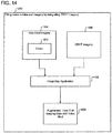
- FIG. 1 illustrates a block diagram of a computing and imaging environment 100 that includes a computational device 102 that integrates intra-oral imagery 104 and CBCT imagery 106, in accordance with certain embodiments.
- the computational device 102 may include any suitable computational device such as a personal computer, a server computer, a mini computer, a mainframe computer, a blade computer, a tablet computer, a touchscreen computing device, a telephony device, a cell phone, a mobile computational device, a dental equipment having a processor, etc., and in certain embodiments the computational device 102 may provide web services or cloud computing services. In certain alternative embodiments, more than one computational device may be used for storing data or performing the operations performed by the computational device 102.
- the intra-oral imagery 104 provides surface data of a patient's crown and the CBCT imagery 106 provides volumetric imagery of a patient's tooth, where the tooth may include both the crown and the root.
- the surface data of the patient's crown may be provided by imagery that is different from intra-oral imagery, and the volumetric imagery may be provided by other types of tomographic imagery, ultrasonic imagery, magnetic resonance imagery (MRI), etc.
- the volumetric imagery comprises three-dimensional imagery and may be represented via voxels.
- the computational device 102 may include an integrating application 108, implemented in certain embodiments in software, hardware, firmware or any combination thereof.
- the integrating application 108 integrates the intra-oral imagery 104 and the CBCT imagery 106 to provide additional functionalities that are not found in either the intra-oral imagery 104 or the CBCT imagery 106 when they are not integrated.
- the computational device 102 is coupled via one or more wired or wireless connections 110 to an intra-oral imaging system 112 and a CBCT imaging system 114, over a network 116.
- the network 116 may comprise a local area network, the Internet, and intranet, a storage area network, or any other suitable network.
- the intra-oral imaging system 112 may include a wand 116 having an intra-oral imaging sensor 118, where in certain embodiments the intra-oral imaging sensor 118 is an intra-oral camera that generates intra-oral imagery of the oral cavity of a patient.
- the CBCT imaging system 114 may include a rotating X-ray equipment 120 that generates cross-sectional CBCT imagery of the soft tissue, hard tissue, teeth, etc. of a patient.
- FIG. 1 illustrates certain embodiments in which an integrating application 108 that executes in the computational device 102 integrates intra-oral imagery 104 generated by an intra-oral imaging system 112 with CBCT imagery 106 generated by a CBCT imaging system 114.
- the intra-oral imagery 104 and the CBCT imagery 106 may be stored in a storage medium (e.g., a disk drive, a floppy drive, a pen drive, a solid state device, an optical drive, etc.), and the storage medium may be coupled to the computational device 102 for reading and processing by the integrating application 108.
- a storage medium e.g., a disk drive, a floppy drive, a pen drive, a solid state device, an optical drive, etc.
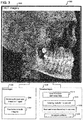
- FIG. 2 illustrates a diagram 200 in which an exemplary intra-oral imagery 202 is shown, in accordance with certain embodiments. Certain exemplary advantages 204 and certain exemplary disadvantages 206 of the intra-oral imagery 202 are also shown, in accordance with certain embodiments.
- the intra-oral imagery 206 shows exemplary crowns (e.g., crowns 208a, 208b, 208c) in the upper arch of the oral cavity of a patient, where the intra-oral imagery 206 may have been acquired via the intra-oral imaging system 112.
- the crown is the portion of the tooth that may be visually seen, and the root is the portion of the tooth that is hidden under the gum.
- FIG. 2 shows that the intra-oral imagery is typically of a high precision 210 in comparison with CBCT imagery. Additionally, no radiation that may cause harm to the patient (shown via reference numeral 212) is needed in acquiring the intra-oral imagery 202. However, the intra-oral imagery 202 does not show the roots of teeth (reference numeral 214) and may have holes 216, where a hole is a portion of the tooth that is not visible in intra-oral imagery. Holes may arise because of malocclusions or for other reasons.
- While, small and medium sized holes may be filled (i.e., the hole is substituted via a simulated surface generated programmatically via the computational device 102) by analyzing the intra-oral imagery 202, larger holes (i.e., holes that exceed certain dimensions) may not be filled by just using data found in intra-oral imagery. Additionally, shiny surfaces of crowns may generate poor quality intra-oral imagery (reference numeral 218).
- FIG. 2 illustrates certain embodiments in which intra-oral imagery may have holes and do not show the entirety of the roots of teeth.
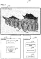
- FIG. 3 illustrates a diagram 300 in which an exemplary CBCT imagery 302, and certain advantages 304 and certain disadvantages 306 of CBCT imagery are shown, in accordance with certain embodiments.
- the entire tooth i.e., the root and the crown
- the few holes that exist may be caused by artifacts as a result of amalgam fillings on tooth (reference numeral 320).
- the CBCT images may be of a lower precision and may be more noisy in comparison to intra-oral imagery (reference numeral 314).
- the boundary between the root and the crown may not be clear (reference numeral 318) as may be seen (reference numeral 320) in the exemplary CBCT imagery 302.
- the fuzzy and indistinct boundary 320 between the crown 322 and the root 324 may be caused by varying radiodensities during the process of acquiring CBCT images.
- motion of the patient may generate inferior quality CBCT imagery.
- FIG. 3 illustrates certain embodiments in which CBCT images may have low precision and have noisy data with the boundary between the root and crown not being clearly demarcated.
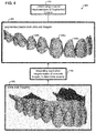
- FIG. 4 illustrates a diagram 400 that shows how an intra-oral imagery 202 is segmented to determine crowns 402 represented via limited length vectors 404, in accordance with certain embodiments.
- the segmentation of the intra-oral imagery 202 to determine crowns 402 may be performed via the integrating application 108 that executes in the computational device 102.
- Exemplary segmented crowns are shown via reference numerals 406a, 406b, 406c.
- the segmented crowns are of a high resolution and show clearly defined edges and are represented via limited length vectors 404.
- a vector has a direction and magnitude in three-dimensional space.
- a limited length vector is a vector whose length is limited.
- the segmented crowns may be represented via data structures or mathematical representations that are different from limited length vectors 404.
- FIG. 4 illustrates certain embodiments in which intra-oral imagery is segmented to determine crowns represented via limited length vectors.
- FIG. 5 illustrates a diagram that shows how an intra-oral imaging system 410 scans the inside of a patient's mouth and generates surface samples of the crowns of a patient's teeth, where the aggregated surface samples may be referred to as a point cloud 412.
- the point cloud 412 may processed by the integrating application 108 executing the computational device 102 to represent the surface of the crowns.
- the crown of the tooth is a solid object, and the surfaces of the crown correspond to the boundaries of the solid object.
- the crown surface may be represented by a surface mesh of node points connected by triangles, quadrilaterals or via different types of polygon meshes.
- a solid mesh may also be used to represent the crown surface.
- the process of creating the mesh is referred to as tessellation.
- the surface corresponding to the crown is represented in three-dimensional space via limited length vectors 414 or via voxels 416 or via other data structures 418.
- the voxels 416 correspond to three-dimensional points on the surface of a crown.
- the limited length vectors 414 may be converted to voxel representation via appropriate three-dimensional coordinate transformations 420.
- the limited length vectors 414 may correspond to the sides of the different types of polygon meshes (e.g., triangles, quadrilaterals, etc.) in the surface representation of the crown.
- FIG. 5 illustrates certain embodiments in which intra-oral imagery is processed to determine crowns represented via limited length vectors or via voxels.
- the limited length vectors or voxels correspond to a surface data representation 422 of the crown.
- Surface data may also be referred to as shape data.
- FIG. 6 illustrates a diagram 500 that shows how voxels 502 represent CBCT imagery 302, in accordance with certain embodiments.
- a voxel e.g., voxel 504
- voxel 504 is a volumetric pixel that is a digital representation of radiodensity in a volumetric framework corresponding to the CBCT imagery 302. The radiodensity may be measured in the Hounsfield scale.
- FIG. 6 an exemplary voxel representation 502 of part of the CBCT imagery 302 is shown.
- the voxel representation 502 has a local origin 504, with X, Y, Z coordinates representing width, depth, and height respectively (shown via reference numerals 506, 508, 510).
- the coordinate of the voxel where the X, Y, Z values are maximum are shown via the reference numeral 512.
- An exemplary voxel 504 and an illustrative column of voxels 514 are also shown.
- Each voxel has a volume defined by the dimensions shown via reference numerals 516, 518, 520.
- limited length vectors of intra-oral imagery are registered to the voxel representation of the CBCT imagery, to determine where the limited length vectors intersect the voxels of the CBCT imagery.
- an intersecting limited length vector 522 is shown to intersect the voxels of the CBCT imagery at various voxels, wherein at least one voxel 524 at which the intersection takes place has a volumetric coordinate of (X,Y,Z) with an associated radiodensity.
- FIG. 6 illustrates certain embodiments in which CBCT imagery is represented via voxels.
- the limited length vectors of the intra-oral imagery intersects the voxels of the CBCT imagery when both are placed in the same coordinate system, wherein each intersection has a X,Y,Z coordinate and a radiodensity.
- the limited length vectors may be one or more of the sides of triangulated tessellations used to represent shape data.
- the limited length vectors may be chained in shape representations.
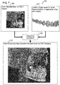
- FIG. 7 illustrates a diagram 600 that shows how the boundary between root and crown is determined in CBCT imagery by integrating intra-oral imagery with CBCT imagery, in accordance with certain embodiments.
- the voxel representation 606 of CBCT imagery is integrated (via the integrating application 108) with the limited length vector representation or voxel representation 607 of the intra-oral imagery to overlay the high resolution clearly segmented crowns of the intra-oral imagery on the low resolution fuzzy crowns of the CBCT imagery (as shown via reference numeral 608), to clearly demarcate the boundary between roots and crowns in the CBCT imagery 602.
- the integration of CBCT imagery and intra-oral imagery results in a type of filtration operation that sharpens the CBCT imagery to determine the boundary between roots and crowns.
- FIG. 7 illustrates certain embodiments in which CBCT imagery is augmented with data from intra-oral imagery to determine the boundary between roots and crowns with a greater degree of accuracy in comparison to using the CBCT imagery alone.
- CBCT imagery is augmented with data from intra-oral imagery to determine the boundary between roots and crowns with a greater degree of accuracy in comparison to using the CBCT imagery alone.
- FIG. 8 illustrates a diagram 609 that shows how surface data and volumetric data are fitted to each other, in accordance with certain embodiments.
- the surface data i.e., the crown surface data
- the volumetric data that represents the tooth may be represented in a second coordinate system (shown via reference numeral 612).
- one or both of the crown surface data and the tooth volumetric data may have to be rotated 614, translated 616, morphed 618, scaled 620, or made to undergo other transformations 622 to appropriately overlap the crown surface data and the tooth volumetric data in a single unified coordinate system.
- the tooth volumetric data is fitted to the crown surface data in the coordinate system of the tooth surface data by appropriate rotations, translations, morphing, scaling, etc., of the tooth volumetric data (as shown via reference numeral 624).
- crown surface data is fitted to the tooth volumetric data in the coordinate system of the tooth volumetric data by appropriate rotations, translations, morphing, scaling, etc., of the crown surface data (as shown via reference numeral 626).
- both the crown surface data and the tooth volumetric data may undergo rotations, translations, morphing, scaling, etc. to fit the crown surface data and tooth volumetric data in a new coordinate system (as shown via reference numeral 628).
- FIG. 9 illustrates a diagram 650 that shows how surface data of the crown is merged to volumetric data of the tooth, in accordance with certain embodiments.
- An empty cube of voxels in the three-dimensional space is populated with the shape data of a crown.
- the surface data of the crown is represented via voxels of a three-dimensional space 652.
- the three-dimensional space 652 with surface data is overlaid on the three-dimensional space 654 that has the volumetric representation of the tooth, to generate the overlay of the surface data on the volumetric data shown in the three-dimensional space 656.
- the fitting of the surface data to the volumetric data may be performed via an iterative closest point (ICP) registration.
- ICP may fit points in surface data to the points in volumetric data.
- the fitting may minimize the sum of square errors with the closest volumetric data points and surface data points.
- the limited length vectors of the surface data are represented as voxels prior to performing the ICP registration.
- the anatomy of brackets, wires, filling or other features on the tooth may often assist in properly registering the surface data to the volumetric data.
- the registration may in various embodiments be performed via optimization techniques, such as simulated annealing, correlation techniques, dynamic programming, linear programming etc.
- a multiplicity of representations of the same object obtained by CBCT, magnetic resonance imagery (MRI), ultrasound imagery, intra-oral imagery based surface data, etc. may be registered to generate a better representation of a crown in comparison to embodiments that do not use data from the multiplicity of representations.
- FIG. 10 illustrates a diagram 670 that shows characteristics of different types of imagery, in accordance with certain embodiments.
- the intra-oral imagery 672 may provide not only the surface data 676 but may also be processed to provide information on reflectivity 678 and translucency 680 of the surface of the objects that are imaged.
- the reflectivity and the translucency of the crown may be different from that of the gingiva, and the intra-oral imagery 672 may be processed to distinguish the crown from the gingiva based on the reflectivity and the translucency differences and the segmentation of the crown may be improved by incorporating such additional information.
- the reflectivity and translucency information may be generated with greater precision in comparison to embodiments where such fringe patterns are not used.
- the volumetric data 682 and the radiodensity information 684 corresponding to the CBCT imagery 674 may be used in association with the surface data 676, reflectivity information 678 and translucency information 680 of the intra-oral imagery 672 to provide additional cues for performing the registration of the surface data 676 and the volumetric data 682.
- Ray tracing mechanisms may also be used for simulating a wide variety of optical effects, such as reflection and refraction, scattering, and dispersion phenomena (such as chromatic aberration) for improving the quality of the different types of images and for registration.
- FIG. 11 illustrates a diagram 688 that shows how surface data 690 extracted from intra-oral imagery is fitted to one or more of model data 694a, 694b,...694n maintained as a library dataset 692.
- the library dataset 692 may include model data for various types of teeth (e.g., incisors, canines, molars, etc.) and also model data for various patient parameters, such as those based on age, gender, ethnicity, etc.
- the surface data 690 may be registered (reference numeral 696) to an appropriately selected model data 694a...694n to provide better quality information to a dental practitioner.
- FIG. 12 illustrates a flowchart 700 for augmenting CBCT imagery with data from intra-oral imagery to determine the boundary between roots and crowns, in accordance with certain embodiments.
- the operations shown in flowchart 700 may be performed via the integrating application 108 that executes in the computational device 102.
- Control starts at block 702 in which the computational device 102 receives intra-oral imagery 104 and CBCT imagery 106.
- the integrating application 108 determines (at block 704) one or more crowns in the intra-oral imagery, wherein the one or more crowns of the intra-oral imagery are represented by limited length vectors or voxels, and the CBCT imagery is represented by voxels.
- Control proceeds to block 706, in which the integrating application 108 integrates the one or more crowns determined in the intra-oral imagery into the CBCT imagery by registering the limited length vectors or voxels that represent the one or more crowns in the intra-oral imagery with the voxels of the CBCT imagery, to determine a boundary between at least one crown and at least one root in the CBCT imagery.
- FIG. 13 illustrates a flowchart 800 for determining a localized area in CBCT imagery to generate a reduced size CBCT imagery, by augmenting CBCT imagery with data from intra-oral imagery, in accordance with certain embodiments.
- the operations shown in flowchart 800 may be performed via the integrating application 108 that executes in the computational device 102.
- Control starts at blocks 802 and 804 in which CBCT imagery and intra-oral imagery are provided to the integrating application 108.
- the integrating application 108 determines (at block 806) an area of interest in the intra-oral imagery, wherein the area of interest corresponds to a location of the one or more crowns determined in the intra-oral imagery via segmentation.
- Control proceeds to block 808 in which the integrating application 108 extracts from the CBCT imagery the area of interest to reduce the size of the CBCT imagery, and the reduced size CBCT imagery is stored (at block 810) in the computational device 102.
- FIG. 13 illustrates certain embodiments in which the size of CBCT imagery is reduced by incorporating an area of interest determined from intra-oral imagery.
- FIG. 14 illustrates a diagram 900 that shows how holes are filled in intra-oral imagery by integrating CBCT imagery with intra-oral imagery, in accordance with certain embodiments.
- an exemplary intra-oral imagery 104 has holes 902 (i.e., areas of the crown of teeth that are not imaged by the intra-oral imaging system 112).
- the integrating application 108 uses the CBCT imagery 106 to fill the holes via the low precision crowns without holes that are found in the CBCT imagery 106, to generate augmented intra-oral imaging data 904 in which all holes are filled.
- a range of radiodensities are determined in voxels of a determined boundary between roots and crowns, and based on the range of radiodensities and the determined boundary, the holes in the intra-oral imagery are filled from selected voxels of the CBCT imagery.
- FIG. 15 illustrates a flowchart 1000 that shows how holes are filled in intra-oral imagery by integrating CBCT imagery with intra-oral imagery, in accordance with certain embodiments.
- the operations shown in flowchart 1000 may be performed via the integrating application 108 that executes in the computational device 102.
- Control starts at block 1002 in which the computational device 102 receives intra-oral imagery 104 and volumetric imagery, such as cone beam computed tomography (CBCT) imagery 106.
- Control proceeds to block 1004, in which the integrating application 108 determines one or more crowns in the intra-oral imagery 104 and the CBCT imagery 106, where the one or more crowns determined by the intra-oral imagery 104 have one or more holes, and where a hole is a part of a tooth that is not visible in the intra-oral imagery.
- the one or more crowns determined in the CBCT imagery are integrated (at block 1006) into the intra-oral imagery 104, to fill the one or more holes in the intra-oral imagery.
- FIGS. 14 and 15 illustrate how holes are filled in intra-oral imagery by integrating information from CBCT imagery. Conversely, if missing or degraded data is found in volumetric imagery, such missing or degraded data may be filled from surface data found in the intra-oral imagery.
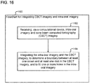
- FIG. 16 illustrates a flowchart 1100 that shows how CBCT imagery 106 is integrated with intra-oral imagery 104, in accordance with certain embodiments.
- the operations shown in flowchart 1100 may be performed via the integrating application 108 that executes in the computational device 102.
- Control starts at block 1102 in which a computational device 102 receives intra-oral imagery 104 and CBCT imagery 106.
- the intra-oral imagery 104 and the CBCT imagery 106 are integrated (at block 1104), to determine a boundary between at least one crown and at least one root in the CBCT imagery 106, and to fill one or more holes in the intra-oral imagery 104.
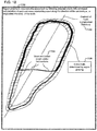
- FIG. 17 illustrates a block diagram 1200 that shows how limited length vectors of intra-oral imagery are registered to voxel data of CBCT or other volumetric imagery, in accordance with certain embodiments.
- the hatched area indicated via reference numeral 1202 indicates an uncertainty region of the CBCT imagery in which the actual tooth boundary of the patient is likely to be found.
- the limited length vectors (or voxels) of the intra-oral imagery are registered to the voxels of the CBCT imagery to determine the intersections 1204.
- FIG. 18 illustrates a block diagram 1300 that shows how region growing is performed to determine the entire tooth by following adjacent voxels with correlated radiodensities at each and every intersecting voxel along the direction of the centroid 1302 of a tooth, in accordance with certain embodiments.
- the centroid is located along a longitudinal direction of the tooth.
- the correlated radiodensities may be determined via correlation windows of different sizes. For example, a cube of voxels with length, breadth, and height of three voxels each may be used as a correlation window to determine which adjacent voxel is most correlated to a previously determined voxel in terms of radiodensities.
- Reference numeral 1306 shows the entire tooth outlined via region growing with seed values starting from the voxels and limited length vector (or surface voxel) intersections 1204 and the associated radiodensities. Other mechanisms may also be adopted for region growing to determine the entire tooth.
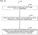
- FIG. 19 illustrates a flowchart 1400 that shows how the root of a tooth is built from intersections of limited length vectors (or surface voxel) and voxels and region growing, in accordance with certain embodiments.
- Control starts at block 1402 where the voxel information at each voxel of a CBCT image is given by a volumetric coordinate X,Y,Z and the radiodensity.
- Control proceeds to block 1404 in which a determination is made as to which voxels of CBCT image and limited length vectors (or voxel) of the boundary of the crown of intra-oral image intersect.
- the root of the tooth is built (at block 1406) from the determined intersections via region growing techniques based on following adjacent radiodensities that are correlated (i.e., similar in magnitude) to each other.
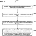
- FIG. 20 illustrates a flowchart 1500 that shows how voxels of tomography (i.e., volumetric) imagery and limited length vectors of shape data are integrated, in accordance with certain embodiments.
- a computational device receives (at block 1502) shape data of a patient's dentition and tomography imagery.
- Vectors that represent one or more crowns in the shape data are determined (at block 1504).
- the vectors are registered with corresponding voxels of the tomography imagery, and volumetric coordinates and radiodensities at the voxels are determined (at block 1506).
- At least one of the patient's teeth is determined via region growing from starting locations that include one or more of the determined volumetric coordinates and the radiodensities at the voxels, and the region growing is performed by following adjacent voxels with closest radiodensities along a direction of a centroid of a tooth (at block 1508).
- voxels referred to as surface voxel
- corresponding to the limited length vectors of the surface data may be used instead of the limited length vectors for registration.
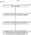
- FIG. 21 illustrates a flowchart 1600 that shows how missing or degraded data in shape data is filled by integrating voxels of tomography imagery and limited length vectors of shape data, in accordance with certain embodiments.
- a computational device receives (at block 1602) shape data of a patient's dentition and tomography imagery. Vectors that represent one or more crowns in the shape data are determined, wherein the one or more crowns have degraded data or missing data (at block 1604). The vectors are registered with corresponding voxels of the tomography imagery, and volumetric coordinates and radiodensities at the voxels are determined (at block 1606).
- At least one of the patient's teeth is determined via region growing from starting locations that include one or more of the determined volumetric coordinates and the radiodensities at the voxels to fill the degraded or the missing data in the one or more crowns of the shape data (at block 1606).
- vectors are registered with corresponding voxels of the tomography imagery to determine volumetric coordinates and radiodensities at the voxels, to determine a tooth with greater precision and to fill missing or degraded data in the shape data.
- the received tomography imagery is obtained with usage of lesser radiation.
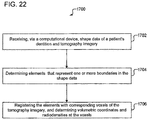
- FIG. 22 illustrates a flowchart 1700 that shows registration of elements (e.g., vectors) in shape data with corresponding voxels in tomographic imagery to determine volumetric coordinates and radiodensities at the voxels, in accordance with certain embodiments.
- a computational device receives (at block 1702) shape data of a patient's dentition and tomography imagery. Elements (e.g., vectors or voxels) that represent one or more boundaries in the shape data are determined (at block 1704). The elements are registered with corresponding voxels of the tomography imagery, and volumetric coordinates and radiodensities at the voxels are determined (at block 1706).
- the boundaries in the shape data delineate one or more crowns of teeth.
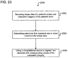
- FIG. 23 illustrates a flowchart 2300 that shows registration of elements in shape data of a patient's crown with corresponding voxels in volumetric imagery, in accordance with certain embodiments.
- Control starts at block 2302 in which shape data of a patient's crown and volumetric imagery of the patient's tooth is received.
- a determination is made (at block 2304) of elements that represent one or more crowns in the shape data.
- a computational device is used to register (at block 2306) the elements with corresponding voxels of the volumetric imagery.
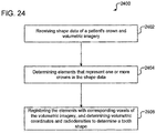
- FIG. 24 illustrates a flowchart 2400 that shows registration of elements in shape data of a patient's crown with corresponding voxels in volumetric imagery to determine tooth shape, in accordance with certain embodiments.
- Control starts at block 2402 in which shape data of a patient's crown and volumetric imagery are received.
- a determination is made (at block 2404) of elements that represent one or more crowns in the shape data.
- the elements are registered (at block 2406) with corresponding voxels of the volumetric imagery by using a computational device, and volumetric coordinates and radiodensities are determined to determine a tooth shape.
- FIGS. 1-24 illustrate certain embodiments in which the tooth of a patient is determined more accurately by integrating information extracted from intra-oral imagery and CBCT imagery. Also, degraded or missing data in the crowns of intra-oral imagery are filled by integrating information extracted from CBCT imagery.
- intra-oral imagery with CBCT imagery both intra-oral imagery and CBCT imagery are enhanced to have greater functionalities and CBCT imagery may be obtained with usage of a lower amount of radiation.
- a volumetric data representation there may be areas of high contrast and low contrast.
- thresholding e.g., by thresholding radiodensities
- the crowns may be thresholded and the borders may be used to seed the segmentation to isolate the roots.
- the volumetric data set may be used to segment itself. This may automatically register the crown root object. This may even be used to register the crown surface data.
- certain embodiments may extract only the centroid of the root.
- Certain embodiments may link the shape and tomography imagery data together in a file system. For example, information may be added to the headers of the image files of both the CBCT and intra-oral scan data to enable viewing software to easily reference one from the other. Alternatively, the viewing software may keep track of which intra-oral scan image and CBCT image files have been registered with one another and store the information in a separate file. In certain embodiments, correlation or optimization techniques may be used to find the intersection points in the image data.
- the output of the processes is a data structure that is an advanced representation of the surface or a volumetric data enhanced by the fusion process of registration of multiple sources of imagery.
- Multidimensional data representation and visualization techniques may be used to display such enhanced surfaces or volumes.
- the collected image data may be rendered and displayed as three-dimensional objects via volumetric rendering and segmentation.
- a computer readable storage medium may include an electronic, magnetic, optical, electromagnetic, or semiconductor system, apparatus, or device, or any suitable combination of the foregoing.
- the computer readable storage medium may also comprise an electrical connection having one or more wires, a portable computer diskette or disk, a hard disk, a random access memory (RAM), a read-only memory (ROM), an erasable programmable read-only memory (EPROM or Flash memory), a portable compact disc read-only memory (CD-ROM), an optical storage device, a magnetic storage device, etc.
- a computer readable storage medium may be any tangible medium that can contain, or store a program for use by or in connection with an instruction execution system, apparatus, or device.
- Computer program code for carrying out operations for aspects of the present invention may be written in any combination of one or more programming languages.
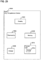
- FIG. 25 illustrates a block diagram that shows certain elements that may be included in the computational device 102, in accordance with certain embodiments.
- the system 2500 may comprise the computational device 102 and may include a circuitry 2502 that may in certain embodiments include at least a processor 2504.
- the system 2500 may also include a memory 2506 (e.g., a volatile memory device), and storage 2508.
- the storage 2508 may include a non-volatile memory device (e.g., EEPROM, ROM, PROM, RAM, DRAM, SRAM, flash, firmware, programmable logic, etc.), magnetic disk drive, optical disk drive, tape drive, etc.
- the storage 2508 may comprise an internal storage device, an attached storage device and/or a network accessible storage device.
- the system 2500 may include a program logic 2510 including code 2512 that may be loaded into the memory 2506 and executed by the processor 2504 or circuitry 2502.
- the program logic 2510 including code 2512 may be stored in the storage 2508.
- the program logic 2510 may be implemented in the circuitry 2502. Therefore, while FIG. 25 shows the program logic 2510 separately from the other elements, the program logic 2510 may be implemented in the memory 2506 and/or the circuitry 2502.
- an embodiment means “one or more (but not all) embodiments of the present invention(s)" unless expressly specified otherwise.
- Devices that are in communication with each other need not be in continuous communication with each other, unless expressly specified otherwise.
- devices that are in communication with each other may communicate directly or indirectly through one or more intermediaries.
Landscapes
- Health & Medical Sciences (AREA)
- Engineering & Computer Science (AREA)
- Life Sciences & Earth Sciences (AREA)
- Physics & Mathematics (AREA)
- Medical Informatics (AREA)
- General Health & Medical Sciences (AREA)
- Biophysics (AREA)
- Public Health (AREA)
- Veterinary Medicine (AREA)
- Animal Behavior & Ethology (AREA)
- Pathology (AREA)
- Biomedical Technology (AREA)
- Heart & Thoracic Surgery (AREA)
- Molecular Biology (AREA)
- Surgery (AREA)
- Theoretical Computer Science (AREA)
- Radiology & Medical Imaging (AREA)
- Nuclear Medicine, Radiotherapy & Molecular Imaging (AREA)
- General Physics & Mathematics (AREA)
- Computer Vision & Pattern Recognition (AREA)
- Dentistry (AREA)
- Oral & Maxillofacial Surgery (AREA)
- Optics & Photonics (AREA)
- High Energy & Nuclear Physics (AREA)
- Geometry (AREA)
- Orthopedic Medicine & Surgery (AREA)
- Physical Education & Sports Medicine (AREA)
- Audiology, Speech & Language Pathology (AREA)
- Rheumatology (AREA)
- Pulmonology (AREA)
- Quality & Reliability (AREA)
- Computer Graphics (AREA)
- Software Systems (AREA)
- Multimedia (AREA)
- Dental Tools And Instruments Or Auxiliary Dental Instruments (AREA)
- Dental Prosthetics (AREA)
- Apparatus For Radiation Diagnosis (AREA)
Claims (12)
- Verfahren, umfassend das Empfangen von Formdaten der Krone eines Patienten und volumetrische Abbildung des Zahnes des Patienten, das Bestimmen von Elementen, die eine oder mehrere Kronen in den Formdaten darstellen, das Verwenden einer Rechenvorrichtung (2500) zum Registrieren der Elemente mit entsprechenden Voxeln der volumetrischen Abbildung und das Bestimmen von volumetrischen Koordinaten und Röntgendichten, die den Voxeln entsprechen, dadurch gekennzeichnet, dass das Verfahren ferner das Bestimmen mindestens einer der Wurzeln des Patienten über Bereichswachstum aus den Ausgangspositionen umfasst, die eine oder mehrere der bestimmten volumetrischen Koordinaten und Röntgendichten an den Voxeln umfassen, wobei der Bereichswachstum durch Identifizieren benachbarter Voxel durchgeführt wird, die korrelierte Röntgendichten besitzen, und wobei die Ausgangspositionen basierend auf Voxeln der volumetrischen Abbildung bestimmt werden, die an entsprechenden Elementen in den Formdaten registriert wurden.
- Verfahren nach Anspruch 1, wobei der Bereichswachstum durch Identifizieren benachbarter Voxel durchgeführt wird, die korrelierte Röntgendichten entlang einer Längsrichtung (1302) des Zahnes des Patienten aufweisen.
- Verfahren nach Anspruch 2, wobei die benachbarten Voxel, die korrelierte Röntgendichten entlang der Längsrichtung des Zahnes des Patienten aufweisen, einen Unsicherheitsbereich (1202) umfassen, innerhalb dessen wahrscheinlich eine tatsächliche Zahngrenze des Zahnes des Patienten gefunden wird.
- Verfahren nach einem der vorhergehenden Ansprüche, wobei:
das Bestimmen der volumetrischen Koordinaten und Röntgendichten zum Bestimmen einer Zahnform verwendet wird, und es ferner das Füllen fehlender oder fehlerhafter Daten in den Formdaten und/oder der volumetrischen Abbildung umfasst, wobei die Zahnform mit größerer Genauigkeit im Vergleich zu der empfangenen volumetrischen Abbildung bestimmt wird, und wobei die Zahnform mit größerer Genauigkeit unter Verwendung von geringerer Strahlung bestimmt wird. - Verfahren nach einem der vorhergehenden Ansprüche, wobei:die volumetrische Abbildung durch eine erste Vielzahl von Voxeln dargestellt wird; unddie eine oder die mehreren Kronen durch eine zweite Vielzahl von Voxeln dargestellt werden; unddie erste Vielzahl von Voxeln und die zweite Vielzahl von Voxeln registriert werden.
- Verfahren nach einem der Ansprüche 1 bis 4, wobei:die Elemente Vektoren sind;Grenzen in den Formdaten der einen oder den mehreren Kronen entsprechen;die eine oder die mehreren Kronen durch eine Vielzahl von Vektoren mit begrenzter Länge dargestellt werden;die volumetrische Abbildung durch eine Vielzahl von Voxeln dargestellt wird; undSchnittpunkte der Vielzahl von Vektoren mit begrenzter Länge und die Vielzahl von Voxeln nachfolgend auf die Registrierung bestimmt werden.
- Verfahren nach Anspruch 1, wobei eine oder mehrere Kronen in den Formdaten durch Segmentierung der Formdaten bestimmt werden.
- Verfahren nach Anspruch 1, wobei die Formdaten aus intraoraler Abbildung stammen und die volumetrische Abbildung eine Kegelstrahl-Computertomographie (CBCT)-Abbildung ist:die intraorale Abbildung eine höhere Präzision aufweist als die CBCT-Abbildung;die volumetrische Abbildung sowohl Wurzeln als auch Zahnkronen beinhaltet; unddie intraorale Abbildung mindestens die Kronen der Zähne beinhaltet, aber nicht die Gesamtheit der Wurzeln der Zähne beinhaltet.
- Verfahren nach Anspruch 8, wobei das Verfahren ferner umfasst:Bestimmen eines Bereichs von Interesse in der intraoralen Abbildung, wobei der Bereich von Interesse einer Position der einen oder mehreren Kronen entspricht, die in der intraoralen Abbildung bestimmt wurden; undExtrahieren des interessierenden Bereichs innerhalb der volumetrischen Abbildung, um eine Größe der volumetrischen Abbildung zu verringern.
- Verfahren nach Anspruch 1, wobei:die Formdaten der Krone des Patienten über einen Abdruck, ein Gipsmodell oder einen intraoralen Scan erhalten werden; unddie volumetrische Abbildung ausgewählt ist aus einer Gruppe, bestehend aus tomographischer Abbildung, Ultraschall-Abbildung, Kegelstrahl-Computertomographie (CBCT)-Abbildung und Magnetresonanz-Abbildung (MRT).
- System (2500), umfassend:einen Speicher; undeinen Prozessor (2504), der mit dem Speicher gekoppelt ist, wobei der Prozessor (2504) die Verfahrensschritte nach einem der Ansprüche 1 bis 10 durchführt.
- Computerlesbares Speichermedium, wobei der Code, der in dem computerlesbaren Speichermedium enthalten ist, wenn er von einem Prozessor (2504) ausgeführt wird, Operationen durchführt, wobei die Operationen die Verfahrensschritte nach einem der Ansprüche 1 bis 10 umfassen.
Priority Applications (2)
| Application Number | Priority Date | Filing Date | Title |
|---|---|---|---|
| DK19158706.2T DK3513712T3 (da) | 2012-12-14 | 2013-12-13 | Integration af intra-orale billeder og volumetriske billeder |
| EP19158706.2A EP3513712B1 (de) | 2012-12-14 | 2013-12-13 | Integration von intraoralen bildern und volumetrischen bildern |
Applications Claiming Priority (1)
| Application Number | Priority Date | Filing Date | Title |
|---|---|---|---|
| US13/715,968 US9135498B2 (en) | 2012-12-14 | 2012-12-14 | Integration of intra-oral imagery and volumetric imagery |
Related Child Applications (1)
| Application Number | Title | Priority Date | Filing Date |
|---|---|---|---|
| EP19158706.2A Division EP3513712B1 (de) | 2012-12-14 | 2013-12-13 | Integration von intraoralen bildern und volumetrischen bildern |
Publications (2)
| Publication Number | Publication Date |
|---|---|
| EP2742857A1 EP2742857A1 (de) | 2014-06-18 |
| EP2742857B1 true EP2742857B1 (de) | 2019-02-27 |
Family
ID=49911180
Family Applications (2)
| Application Number | Title | Priority Date | Filing Date |
|---|---|---|---|
| EP13197241.6A Active EP2742857B1 (de) | 2012-12-14 | 2013-12-13 | Integration von intraoraler Abbildung und volumetrischer Abbildung |
| EP19158706.2A Active EP3513712B1 (de) | 2012-12-14 | 2013-12-13 | Integration von intraoralen bildern und volumetrischen bildern |
Family Applications After (1)
| Application Number | Title | Priority Date | Filing Date |
|---|---|---|---|
| EP19158706.2A Active EP3513712B1 (de) | 2012-12-14 | 2013-12-13 | Integration von intraoralen bildern und volumetrischen bildern |
Country Status (5)
| Country | Link |
|---|---|
| US (4) | US9135498B2 (de) |
| EP (2) | EP2742857B1 (de) |
| JP (1) | JP6327845B2 (de) |
| CN (1) | CN103860191B (de) |
| DK (2) | DK2742857T3 (de) |
Families Citing this family (77)
| Publication number | Priority date | Publication date | Assignee | Title |
|---|---|---|---|---|
| JP5744084B2 (ja) * | 2013-03-06 | 2015-07-01 | 株式会社モリタ製作所 | 歯科用画像表示装置、歯科用施術装置及び歯科用画像表示装置の作動方法 |
| US9626462B2 (en) * | 2014-07-01 | 2017-04-18 | 3M Innovative Properties Company | Detecting tooth wear using intra-oral 3D scans |
| US10449016B2 (en) | 2014-09-19 | 2019-10-22 | Align Technology, Inc. | Arch adjustment appliance |
| US9610141B2 (en) | 2014-09-19 | 2017-04-04 | Align Technology, Inc. | Arch expanding appliance |
| US9744001B2 (en) | 2014-11-13 | 2017-08-29 | Align Technology, Inc. | Dental appliance with cavity for an unerupted or erupting tooth |
| US10504386B2 (en) | 2015-01-27 | 2019-12-10 | Align Technology, Inc. | Training method and system for oral-cavity-imaging-and-modeling equipment |
| FR3032282B1 (fr) * | 2015-02-03 | 2018-09-14 | Francois Duret | Dispositif de visualisation de l'interieur d'une bouche |
| DE102015212806A1 (de) * | 2015-07-08 | 2017-01-12 | Sirona Dental Systems Gmbh | System und Verfahren zum Scannen von anatomischen Strukturen und zum Darstellen eines Scanergebnisses |
| US11554000B2 (en) | 2015-11-12 | 2023-01-17 | Align Technology, Inc. | Dental attachment formation structure |
| US11931222B2 (en) | 2015-11-12 | 2024-03-19 | Align Technology, Inc. | Dental attachment formation structures |
| US11596502B2 (en) | 2015-12-09 | 2023-03-07 | Align Technology, Inc. | Dental attachment placement structure |
| US11103330B2 (en) | 2015-12-09 | 2021-08-31 | Align Technology, Inc. | Dental attachment placement structure |
| CN105455906B (zh) * | 2015-12-15 | 2019-03-29 | 杭州一牙数字口腔有限公司 | 一种重建患者牙根的方法 |
| CN105528807A (zh) * | 2016-01-29 | 2016-04-27 | 北京正齐口腔医疗技术有限公司 | 排牙设计方法及装置 |
| JP6750812B2 (ja) * | 2016-05-06 | 2020-09-02 | 岳 芳本 | 治療支援システム、治療支援装置、治療支援方法、及びコンピュータプログラム |
| EP3988048B1 (de) | 2016-06-17 | 2024-01-17 | Align Technology, Inc. | Leistungsüberwachung einer kieferorthopädischen vorrichtung |
| US20210244372A1 (en) * | 2016-06-17 | 2021-08-12 | Carestream Dental Technology Topco Limited | Method and System for 3D Cephalometric Analysis |
| US10470847B2 (en) | 2016-06-17 | 2019-11-12 | Align Technology, Inc. | Intraoral appliances with sensing |
| CN115869098A (zh) * | 2016-07-27 | 2023-03-31 | 阿莱恩技术有限公司 | 具有牙科诊断能力的口内扫描仪 |
| US10507087B2 (en) | 2016-07-27 | 2019-12-17 | Align Technology, Inc. | Methods and apparatuses for forming a three-dimensional volumetric model of a subject's teeth |
| CN106327535B (zh) * | 2016-08-16 | 2020-11-17 | 苏州迪凯尔医疗科技有限公司 | Cbct的牙根与口内扫描的牙冠的融合方法 |
| KR101865701B1 (ko) * | 2016-10-06 | 2018-06-11 | 주식회사 메가젠임플란트 | 모바일 연동 임플란트 진단 시스템 |
| EP3534832B1 (de) | 2016-11-04 | 2023-09-27 | Align Technology, Inc. | Verfahren und vorrichtungen für zahnbilder |
| US11559378B2 (en) | 2016-11-17 | 2023-01-24 | James R. Glidewell Dental Ceramics, Inc. | Scanning dental impressions |
| US11026831B2 (en) | 2016-12-02 | 2021-06-08 | Align Technology, Inc. | Dental appliance features for speech enhancement |
| WO2018102770A1 (en) | 2016-12-02 | 2018-06-07 | Align Technology, Inc. | Force control, stop mechanism, regulating structure of removable arch adjustment appliance |
| US11273011B2 (en) | 2016-12-02 | 2022-03-15 | Align Technology, Inc. | Palatal expanders and methods of expanding a palate |
| US10993783B2 (en) | 2016-12-02 | 2021-05-04 | Align Technology, Inc. | Methods and apparatuses for customizing a rapid palatal expander |
| WO2018111491A1 (en) | 2016-12-13 | 2018-06-21 | Ormco Corporation | Methods and systems for registering multiple dental imageries |
| US10548700B2 (en) | 2016-12-16 | 2020-02-04 | Align Technology, Inc. | Dental appliance etch template |
| CN108205806B (zh) * | 2016-12-20 | 2020-10-09 | 北京大学 | 一种锥束ct图像三维颅面结构的自动解析方法 |
| US10779718B2 (en) | 2017-02-13 | 2020-09-22 | Align Technology, Inc. | Cheek retractor and mobile device holder |
| US10613515B2 (en) | 2017-03-31 | 2020-04-07 | Align Technology, Inc. | Orthodontic appliances including at least partially un-erupted teeth and method of forming them |
| US11045283B2 (en) | 2017-06-09 | 2021-06-29 | Align Technology, Inc. | Palatal expander with skeletal anchorage devices |
| US10639134B2 (en) | 2017-06-26 | 2020-05-05 | Align Technology, Inc. | Biosensor performance indicator for intraoral appliances |
| ES2959341T3 (es) * | 2017-06-30 | 2024-02-23 | Dental Imaging Technologies Corp | Mapeo de superficies usando un escáner intraoral con capacidades de penetración |
| JP2020525258A (ja) | 2017-06-30 | 2020-08-27 | プロマトン・ホールディング・ベー・フェー | 深層学習法を使用する3d歯顎顔面構造の分類および3dモデリング |
| US10687917B2 (en) * | 2017-07-14 | 2020-06-23 | Dental Smartmirror, Inc. | Using immersive photographs to guide placement of orthodontic brackets, and applications thereof |
| US10885521B2 (en) | 2017-07-17 | 2021-01-05 | Align Technology, Inc. | Method and apparatuses for interactive ordering of dental aligners |
| WO2019018784A1 (en) | 2017-07-21 | 2019-01-24 | Align Technology, Inc. | ANCHOR OF CONTOUR PALATIN |
| CN115462921A (zh) | 2017-07-27 | 2022-12-13 | 阿莱恩技术有限公司 | 牙齿着色、透明度和上釉 |
| US10517482B2 (en) | 2017-07-27 | 2019-12-31 | Align Technology, Inc. | Optical coherence tomography for orthodontic aligners |
| US11116605B2 (en) | 2017-08-15 | 2021-09-14 | Align Technology, Inc. | Buccal corridor assessment and computation |
| US11123156B2 (en) | 2017-08-17 | 2021-09-21 | Align Technology, Inc. | Dental appliance compliance monitoring |
| EP3462373A1 (de) | 2017-10-02 | 2019-04-03 | Promaton Holding B.V. | Automatisierte klassifizierung und taxonomie von 3d-zahndaten mit tieflernverfahren |
| US10813720B2 (en) | 2017-10-05 | 2020-10-27 | Align Technology, Inc. | Interproximal reduction templates |
| CN111565668B (zh) | 2017-10-27 | 2022-06-07 | 阿莱恩技术有限公司 | 替代咬合调整结构 |
| US11576752B2 (en) | 2017-10-31 | 2023-02-14 | Align Technology, Inc. | Dental appliance having selective occlusal loading and controlled intercuspation |
| US11096763B2 (en) | 2017-11-01 | 2021-08-24 | Align Technology, Inc. | Automatic treatment planning |
| WO2019100022A1 (en) | 2017-11-17 | 2019-05-23 | Align Technology, Inc. | Orthodontic retainers |
| EP3716885B1 (de) | 2017-11-30 | 2023-08-30 | Align Technology, Inc. | Sensoren umfassende orthodontische intraorale geräte |
| WO2019118876A1 (en) | 2017-12-15 | 2019-06-20 | Align Technology, Inc. | Closed loop adaptive orthodontic treatment methods and apparatuses |
| EP3503038A1 (de) * | 2017-12-22 | 2019-06-26 | Promaton Holding B.V. | Automatisierte 3d-vorhersage einer wurzelform mithilfe von tiefenlernverfahren |
| US10980613B2 (en) | 2017-12-29 | 2021-04-20 | Align Technology, Inc. | Augmented reality enhancements for dental practitioners |
| CN111655191B (zh) | 2018-01-26 | 2022-04-08 | 阿莱恩技术有限公司 | 诊断性口内扫描和追踪 |
| US10803675B2 (en) * | 2018-02-20 | 2020-10-13 | Ivoclar Vivadent Ag | Dental model attributes transfer |
| US11937991B2 (en) | 2018-03-27 | 2024-03-26 | Align Technology, Inc. | Dental attachment placement structure |
| AU2019251474A1 (en) | 2018-04-11 | 2020-10-29 | Align Technology, Inc. | Releasable palatal expanders |
| EP3561778A1 (de) | 2018-04-26 | 2019-10-30 | Promaton Holding B.V. | Automatisierte korrektur von metallbehafteten voxeldarstellungen von röntgendaten mit hilfe von tiefenlerntechniken |
| CN108986111B (zh) * | 2018-07-02 | 2021-08-17 | 西安增材制造国家研究院有限公司 | 一种用于计算机辅助隐形正畸的三维牙颌模型分割方法 |
| EP3591616A1 (de) * | 2018-07-03 | 2020-01-08 | Promaton Holding B.V. | Automatisierte bestimmung einer kanonischen lage eines 3d-zahnmodells und überlagerung von 3d-zahnstrukturen mittels tiefenlernen |
| US20210322138A1 (en) * | 2018-08-23 | 2021-10-21 | Carestream Dental Technology Shanghai Co., Ltd. | Hybrid method of acquiring 3d data using intraoral scanner |
| ES2745351A1 (es) * | 2018-08-28 | 2020-02-28 | Estela Salvador Albalat | Sistema y metodo para la colocacion de implantes dentales mediante escaner 3d intraoral |
| EP3620130A1 (de) * | 2018-09-04 | 2020-03-11 | Promaton Holding B.V. | Automatische planung zahnmedizinischer behandlungen mit deep learning |
| US10991091B2 (en) | 2018-10-30 | 2021-04-27 | Diagnocat Inc. | System and method for an automated parsing pipeline for anatomical localization and condition classification |
| EP3673864A1 (de) * | 2018-12-28 | 2020-07-01 | Trophy | Zahn segmentierung unter verwendung einer zahnregistrierung |
| WO2020141366A1 (en) * | 2018-12-31 | 2020-07-09 | 3M Innovative Properties Company | Combining data from multiple dental anatomy scans |
| CN109961427A (zh) * | 2019-03-12 | 2019-07-02 | 北京羽医甘蓝信息技术有限公司 | 基于深度学习的全景片根尖周炎识别的方法和装置 |
| US11622843B2 (en) | 2019-06-25 | 2023-04-11 | James R. Glidewell Dental Ceramics, Inc. | Processing digital dental impression |
| US11540906B2 (en) | 2019-06-25 | 2023-01-03 | James R. Glidewell Dental Ceramics, Inc. | Processing digital dental impression |
| US11534271B2 (en) | 2019-06-25 | 2022-12-27 | James R. Glidewell Dental Ceramics, Inc. | Processing CT scan of dental impression |
| KR102292875B1 (ko) * | 2019-08-08 | 2021-08-24 | 오스템임플란트 주식회사 | 치과용 가이드 디자인 방법 및 그 장치 |
| KR102311388B1 (ko) * | 2019-09-26 | 2021-10-13 | 주식회사 메디트 | 3차원 데이터 정렬 장치 및 3차원 데이터 정렬 방법 |
| CN110974453A (zh) * | 2019-12-25 | 2020-04-10 | 中国医科大学附属口腔医院 | 一种配合3d打印模型设计埋伏牙牵引方向的数字化方法 |
| CN113243932A (zh) * | 2020-02-12 | 2021-08-13 | 阿里巴巴集团控股有限公司 | 口腔健康检测系统、相关方法、装置及设备 |
| CN111862171B (zh) * | 2020-08-04 | 2021-04-13 | 万申(北京)科技有限公司 | 基于多视图融合的cbct与激光扫描点云数据牙齿配准方法 |
| US11544846B2 (en) | 2020-08-27 | 2023-01-03 | James R. Glidewell Dental Ceramics, Inc. | Out-of-view CT scan detection |
Family Cites Families (23)
| Publication number | Priority date | Publication date | Assignee | Title |
|---|---|---|---|---|
| US6409504B1 (en) * | 1997-06-20 | 2002-06-25 | Align Technology, Inc. | Manipulating a digital dentition model to form models of individual dentition components |
| US7063532B1 (en) | 1997-06-20 | 2006-06-20 | Align Technology, Inc. | Subdividing a digital dentition model |
| US7247021B2 (en) * | 1997-06-20 | 2007-07-24 | Align Technology, Inc. | Subdividing a digital dentition model |
| US5975893A (en) * | 1997-06-20 | 1999-11-02 | Align Technology, Inc. | Method and system for incrementally moving teeth |
| US9421074B2 (en) | 2001-04-13 | 2016-08-23 | Orametrix, Inc. | Unified three dimensional virtual craniofacial and dentition model and uses thereof |
| US9412166B2 (en) | 2001-04-13 | 2016-08-09 | Orametrix, Inc. | Generating three dimensional digital dentition models from surface and volume scan data |
| JP4499422B2 (ja) | 2002-01-16 | 2010-07-07 | アイ−デント イメージング, インコーポレイテッド | 口腔インプラントテンプレート |
| US7324661B2 (en) * | 2004-04-30 | 2008-01-29 | Colgate-Palmolive Company | Computer-implemented system and method for automated and highly accurate plaque analysis, reporting, and visualization |
| US20060127854A1 (en) * | 2004-12-14 | 2006-06-15 | Huafeng Wen | Image based dentition record digitization |
| US7844429B2 (en) * | 2006-07-19 | 2010-11-30 | Align Technology, Inc. | System and method for three-dimensional complete tooth modeling |
| US9111372B2 (en) | 2006-08-11 | 2015-08-18 | Visionary Technologies, Inc. | System and method for object identification and anomaly detection |
| JP5374382B2 (ja) | 2007-01-10 | 2013-12-25 | ノベル バイオケア サーヴィシィズ アーゲー | 歯科用計画および生産のための方法およびシステム |
| DE102007001684B4 (de) | 2007-01-11 | 2023-01-26 | Sicat Gmbh & Co. Kg | Bildregistrierung |
| US7865259B2 (en) | 2007-12-06 | 2011-01-04 | Align Technology, Inc. | System and method for improved dental geometry representation |
| EP2280651A2 (de) * | 2008-05-16 | 2011-02-09 | Geodigm Corporation | Verfahren und vorrichtung zur kombination von 3d-dentalscans mit anderen 3d-datensätzen |
| EP2322114A1 (de) | 2009-11-16 | 2011-05-18 | Nobel Biocare Services AG | System und Verfahren zur Planung eines ersten und zweiten Zahnersatzes |
| EP2560572B1 (de) | 2010-04-20 | 2019-06-12 | Dental Imaging Technologies Corporation | Minimierung und entfernung von artefakten aus einem dreidimensionalen zahnärztlichen röntgendatensatz mithilfe von oberflächenerfassungsinformationen |
| GB201009725D0 (en) | 2010-06-11 | 2010-07-21 | Univ Leuven Kath | Method of quantifying local bone loss |
| WO2012007003A1 (en) * | 2010-07-12 | 2012-01-19 | 3Shape A/S | 3D modeling of an object using textural features |
| US20120214121A1 (en) | 2011-01-26 | 2012-08-23 | Greenberg Surgical Technologies, Llc | Orthodontic Treatment Integrating Optical Scanning and CT Scan Data |
| KR101315032B1 (ko) * | 2012-11-08 | 2013-10-08 | 주식회사 메가젠임플란트 | 임플란트 영상 생성방법 및 임플란트 영상 생성 시스템 |
| US20140227655A1 (en) | 2013-02-12 | 2014-08-14 | Ormco Corporation | Integration of model data, surface data, and volumetric data |
| CA2936023A1 (en) * | 2014-01-10 | 2015-07-16 | Ao Technology Ag | Method for generating a 3d reference computer model of at least one anatomical structure |
-
2012
- 2012-12-14 US US13/715,968 patent/US9135498B2/en active Active
-
2013
- 2013-12-13 EP EP13197241.6A patent/EP2742857B1/de active Active
- 2013-12-13 JP JP2013257971A patent/JP6327845B2/ja active Active
- 2013-12-13 DK DK13197241.6T patent/DK2742857T3/da active
- 2013-12-13 DK DK19158706.2T patent/DK3513712T3/da active
- 2013-12-13 EP EP19158706.2A patent/EP3513712B1/de active Active
- 2013-12-16 CN CN201310688041.XA patent/CN103860191B/zh active Active
-
2015
- 2015-09-08 US US14/847,651 patent/US9904999B2/en active Active
-
2018
- 2018-02-26 US US15/905,528 patent/US10204414B2/en active Active
-
2019
- 2019-02-07 US US16/270,151 patent/US20190172200A1/en not_active Abandoned
Non-Patent Citations (1)
| Title |
|---|
| None * |
Also Published As
| Publication number | Publication date |
|---|---|
| US20140169648A1 (en) | 2014-06-19 |
| US10204414B2 (en) | 2019-02-12 |
| DK2742857T3 (da) | 2019-05-20 |
| US9135498B2 (en) | 2015-09-15 |
| EP3513712A1 (de) | 2019-07-24 |
| JP6327845B2 (ja) | 2018-05-23 |
| US9904999B2 (en) | 2018-02-27 |
| US20190172200A1 (en) | 2019-06-06 |
| CN103860191A (zh) | 2014-06-18 |
| JP2014117611A (ja) | 2014-06-30 |
| US20160042509A1 (en) | 2016-02-11 |
| DK3513712T3 (da) | 2021-07-05 |
| CN103860191B (zh) | 2018-04-13 |
| EP3513712B1 (de) | 2021-03-31 |
| EP2742857A1 (de) | 2014-06-18 |
| US20180182098A1 (en) | 2018-06-28 |
Similar Documents
| Publication | Publication Date | Title |
|---|---|---|
| US10204414B2 (en) | Integration of intra-oral imagery and volumetric imagery | |
| US10368719B2 (en) | Registering shape data extracted from intra-oral imagery to digital reconstruction of teeth for determining position and orientation of roots | |
| US20140227655A1 (en) | Integration of model data, surface data, and volumetric data | |
| JP7289026B2 (ja) | ハイブリッドメッシュセグメンテーションのための方法及び装置 | |
| JP7168644B2 (ja) | 口腔内画像の選択及びロック | |
| JP2014117611A5 (de) | ||
| JP7386215B2 (ja) | 歯列メッシュ矯正具除去のための方法および装置 | |
| US9245374B2 (en) | Space carving in 3D data acquisition | |
| US20170135655A1 (en) | Facial texture mapping to volume image | |
| EP2973401B1 (de) | Verfahren zur herstellung von zahnoberflächen aus röntgenstrahlenabtastung eines negativabdrucks | |
| US20180146934A1 (en) | Method and apparatus for x-ray scan of occlusal dental casts | |
| EP3346943A1 (de) | Verfahren und system zur segmentierung von hybridem mesh | |
| Hussien et al. | Stereo photogrammetry vs computed tomography for 3D medical measurements | |
| CN111553941A (zh) | 用户口腔全景视图的合成方法及装置、电子设备 | |
| Barone et al. | Customised 3D Tooth Modeling by Minimally Invasive Imaging Modalities | |
| KR20240070699A (ko) | 구강 내 이미지의 선택 및 잠금 |
Legal Events
| Date | Code | Title | Description |
|---|---|---|---|
| PUAI | Public reference made under article 153(3) epc to a published international application that has entered the european phase |
Free format text: ORIGINAL CODE: 0009012 |
|
| 17P | Request for examination filed |
Effective date: 20131213 |
|
| AK | Designated contracting states |
Kind code of ref document: A1 Designated state(s): AL AT BE BG CH CY CZ DE DK EE ES FI FR GB GR HR HU IE IS IT LI LT LU LV MC MK MT NL NO PL PT RO RS SE SI SK SM TR |
|
| AX | Request for extension of the european patent |
Extension state: BA ME |
|
| R17P | Request for examination filed (corrected) |
Effective date: 20141218 |
|
| RBV | Designated contracting states (corrected) |
Designated state(s): AL AT BE BG CH CY CZ DE DK EE ES FI FR GB GR HR HU IE IS IT LI LT LU LV MC MK MT NL NO PL PT RO RS SE SI SK SM TR |
|
| 17Q | First examination report despatched |
Effective date: 20151117 |
|
| RIC1 | Information provided on ipc code assigned before grant |
Ipc: A61B 5/00 20060101AFI20180716BHEP Ipc: A61B 5/107 20060101ALI20180716BHEP Ipc: A61C 7/00 20060101ALN20180716BHEP Ipc: A61B 5/11 20060101ALI20180716BHEP Ipc: G06T 3/00 20060101ALN20180716BHEP Ipc: A61B 6/14 20060101ALI20180716BHEP Ipc: A61B 8/08 20060101ALN20180716BHEP |
|
| GRAP | Despatch of communication of intention to grant a patent |
Free format text: ORIGINAL CODE: EPIDOSNIGR1 |
|
| STAA | Information on the status of an ep patent application or granted ep patent |
Free format text: STATUS: GRANT OF PATENT IS INTENDED |
|
| INTG | Intention to grant announced |
Effective date: 20180913 |
|
| INTG | Intention to grant announced |
Effective date: 20180913 |
|
| GRAS | Grant fee paid |
Free format text: ORIGINAL CODE: EPIDOSNIGR3 |
|
| GRAA | (expected) grant |
Free format text: ORIGINAL CODE: 0009210 |
|
| STAA | Information on the status of an ep patent application or granted ep patent |
Free format text: STATUS: THE PATENT HAS BEEN GRANTED |
|
| AK | Designated contracting states |
Kind code of ref document: B1 Designated state(s): AL AT BE BG CH CY CZ DE DK EE ES FI FR GB GR HR HU IE IS IT LI LT LU LV MC MK MT NL NO PL PT RO RS SE SI SK SM TR |
|
| REG | Reference to a national code |
Ref country code: GB Ref legal event code: FG4D |
|
| REG | Reference to a national code |
Ref country code: CH Ref legal event code: EP |
|
| REG | Reference to a national code |
Ref country code: AT Ref legal event code: REF Ref document number: 1100162 Country of ref document: AT Kind code of ref document: T Effective date: 20190315 |
|
| REG | Reference to a national code |
Ref country code: IE Ref legal event code: FG4D |
|
| REG | Reference to a national code |
Ref country code: DE Ref legal event code: R096 Ref document number: 602013051348 Country of ref document: DE |
|
| REG | Reference to a national code |
Ref country code: DK Ref legal event code: T3 Effective date: 20190513 |
|
| REG | Reference to a national code |
Ref country code: NL Ref legal event code: FP |
|
| REG | Reference to a national code |
Ref country code: LT Ref legal event code: MG4D |
|
| PG25 | Lapsed in a contracting state [announced via postgrant information from national office to epo] |
Ref country code: NO Free format text: LAPSE BECAUSE OF FAILURE TO SUBMIT A TRANSLATION OF THE DESCRIPTION OR TO PAY THE FEE WITHIN THE PRESCRIBED TIME-LIMIT Effective date: 20190527 Ref country code: SE Free format text: LAPSE BECAUSE OF FAILURE TO SUBMIT A TRANSLATION OF THE DESCRIPTION OR TO PAY THE FEE WITHIN THE PRESCRIBED TIME-LIMIT Effective date: 20190227 Ref country code: PT Free format text: LAPSE BECAUSE OF FAILURE TO SUBMIT A TRANSLATION OF THE DESCRIPTION OR TO PAY THE FEE WITHIN THE PRESCRIBED TIME-LIMIT Effective date: 20190627 Ref country code: LT Free format text: LAPSE BECAUSE OF FAILURE TO SUBMIT A TRANSLATION OF THE DESCRIPTION OR TO PAY THE FEE WITHIN THE PRESCRIBED TIME-LIMIT Effective date: 20190227 |
|
| PG25 | Lapsed in a contracting state [announced via postgrant information from national office to epo] |
Ref country code: LV Free format text: LAPSE BECAUSE OF FAILURE TO SUBMIT A TRANSLATION OF THE DESCRIPTION OR TO PAY THE FEE WITHIN THE PRESCRIBED TIME-LIMIT Effective date: 20190227 Ref country code: HR Free format text: LAPSE BECAUSE OF FAILURE TO SUBMIT A TRANSLATION OF THE DESCRIPTION OR TO PAY THE FEE WITHIN THE PRESCRIBED TIME-LIMIT Effective date: 20190227 Ref country code: BG Free format text: LAPSE BECAUSE OF FAILURE TO SUBMIT A TRANSLATION OF THE DESCRIPTION OR TO PAY THE FEE WITHIN THE PRESCRIBED TIME-LIMIT Effective date: 20190527 Ref country code: GR Free format text: LAPSE BECAUSE OF FAILURE TO SUBMIT A TRANSLATION OF THE DESCRIPTION OR TO PAY THE FEE WITHIN THE PRESCRIBED TIME-LIMIT Effective date: 20190528 Ref country code: IS Free format text: LAPSE BECAUSE OF FAILURE TO SUBMIT A TRANSLATION OF THE DESCRIPTION OR TO PAY THE FEE WITHIN THE PRESCRIBED TIME-LIMIT Effective date: 20190627 Ref country code: RS Free format text: LAPSE BECAUSE OF FAILURE TO SUBMIT A TRANSLATION OF THE DESCRIPTION OR TO PAY THE FEE WITHIN THE PRESCRIBED TIME-LIMIT Effective date: 20190227 |
|
| REG | Reference to a national code |
Ref country code: AT Ref legal event code: MK05 Ref document number: 1100162 Country of ref document: AT Kind code of ref document: T Effective date: 20190227 |
|
| PG25 | Lapsed in a contracting state [announced via postgrant information from national office to epo] |
Ref country code: ES Free format text: LAPSE BECAUSE OF FAILURE TO SUBMIT A TRANSLATION OF THE DESCRIPTION OR TO PAY THE FEE WITHIN THE PRESCRIBED TIME-LIMIT Effective date: 20190227 Ref country code: EE Free format text: LAPSE BECAUSE OF FAILURE TO SUBMIT A TRANSLATION OF THE DESCRIPTION OR TO PAY THE FEE WITHIN THE PRESCRIBED TIME-LIMIT Effective date: 20190227 Ref country code: CZ Free format text: LAPSE BECAUSE OF FAILURE TO SUBMIT A TRANSLATION OF THE DESCRIPTION OR TO PAY THE FEE WITHIN THE PRESCRIBED TIME-LIMIT Effective date: 20190227 Ref country code: RO Free format text: LAPSE BECAUSE OF FAILURE TO SUBMIT A TRANSLATION OF THE DESCRIPTION OR TO PAY THE FEE WITHIN THE PRESCRIBED TIME-LIMIT Effective date: 20190227 Ref country code: AL Free format text: LAPSE BECAUSE OF FAILURE TO SUBMIT A TRANSLATION OF THE DESCRIPTION OR TO PAY THE FEE WITHIN THE PRESCRIBED TIME-LIMIT Effective date: 20190227 Ref country code: SK Free format text: LAPSE BECAUSE OF FAILURE TO SUBMIT A TRANSLATION OF THE DESCRIPTION OR TO PAY THE FEE WITHIN THE PRESCRIBED TIME-LIMIT Effective date: 20190227 |
|
| REG | Reference to a national code |
Ref country code: DE Ref legal event code: R097 Ref document number: 602013051348 Country of ref document: DE |
|
| PG25 | Lapsed in a contracting state [announced via postgrant information from national office to epo] |
Ref country code: SM Free format text: LAPSE BECAUSE OF FAILURE TO SUBMIT A TRANSLATION OF THE DESCRIPTION OR TO PAY THE FEE WITHIN THE PRESCRIBED TIME-LIMIT Effective date: 20190227 Ref country code: PL Free format text: LAPSE BECAUSE OF FAILURE TO SUBMIT A TRANSLATION OF THE DESCRIPTION OR TO PAY THE FEE WITHIN THE PRESCRIBED TIME-LIMIT Effective date: 20190227 |
|
| PG25 | Lapsed in a contracting state [announced via postgrant information from national office to epo] |
Ref country code: AT Free format text: LAPSE BECAUSE OF FAILURE TO SUBMIT A TRANSLATION OF THE DESCRIPTION OR TO PAY THE FEE WITHIN THE PRESCRIBED TIME-LIMIT Effective date: 20190227 |
|
| PLBE | No opposition filed within time limit |
Free format text: ORIGINAL CODE: 0009261 |
|
| STAA | Information on the status of an ep patent application or granted ep patent |
Free format text: STATUS: NO OPPOSITION FILED WITHIN TIME LIMIT |
|
| 26N | No opposition filed |
Effective date: 20191128 |
|
| PG25 | Lapsed in a contracting state [announced via postgrant information from national office to epo] |
Ref country code: SI Free format text: LAPSE BECAUSE OF FAILURE TO SUBMIT A TRANSLATION OF THE DESCRIPTION OR TO PAY THE FEE WITHIN THE PRESCRIBED TIME-LIMIT Effective date: 20190227 |
|
| PG25 | Lapsed in a contracting state [announced via postgrant information from national office to epo] |
Ref country code: TR Free format text: LAPSE BECAUSE OF FAILURE TO SUBMIT A TRANSLATION OF THE DESCRIPTION OR TO PAY THE FEE WITHIN THE PRESCRIBED TIME-LIMIT Effective date: 20190227 |
|
| REG | Reference to a national code |
Ref country code: CH Ref legal event code: PL |
|
| PG25 | Lapsed in a contracting state [announced via postgrant information from national office to epo] |
Ref country code: MC Free format text: LAPSE BECAUSE OF FAILURE TO SUBMIT A TRANSLATION OF THE DESCRIPTION OR TO PAY THE FEE WITHIN THE PRESCRIBED TIME-LIMIT Effective date: 20190227 |
|
| GBPC | Gb: european patent ceased through non-payment of renewal fee |
Effective date: 20191213 |
|
| PG25 | Lapsed in a contracting state [announced via postgrant information from national office to epo] |
Ref country code: LU Free format text: LAPSE BECAUSE OF NON-PAYMENT OF DUE FEES Effective date: 20191213 Ref country code: GB Free format text: LAPSE BECAUSE OF NON-PAYMENT OF DUE FEES Effective date: 20191213 Ref country code: IE Free format text: LAPSE BECAUSE OF NON-PAYMENT OF DUE FEES Effective date: 20191213 |
|
| PG25 | Lapsed in a contracting state [announced via postgrant information from national office to epo] |
Ref country code: CH Free format text: LAPSE BECAUSE OF NON-PAYMENT OF DUE FEES Effective date: 20191231 Ref country code: LI Free format text: LAPSE BECAUSE OF NON-PAYMENT OF DUE FEES Effective date: 20191231 |
|
| PG25 | Lapsed in a contracting state [announced via postgrant information from national office to epo] |
Ref country code: CY Free format text: LAPSE BECAUSE OF FAILURE TO SUBMIT A TRANSLATION OF THE DESCRIPTION OR TO PAY THE FEE WITHIN THE PRESCRIBED TIME-LIMIT Effective date: 20190227 |
|
| PG25 | Lapsed in a contracting state [announced via postgrant information from national office to epo] |
Ref country code: MT Free format text: LAPSE BECAUSE OF FAILURE TO SUBMIT A TRANSLATION OF THE DESCRIPTION OR TO PAY THE FEE WITHIN THE PRESCRIBED TIME-LIMIT Effective date: 20190227 Ref country code: HU Free format text: LAPSE BECAUSE OF FAILURE TO SUBMIT A TRANSLATION OF THE DESCRIPTION OR TO PAY THE FEE WITHIN THE PRESCRIBED TIME-LIMIT; INVALID AB INITIO Effective date: 20131213 |
|
| PG25 | Lapsed in a contracting state [announced via postgrant information from national office to epo] |
Ref country code: MK Free format text: LAPSE BECAUSE OF FAILURE TO SUBMIT A TRANSLATION OF THE DESCRIPTION OR TO PAY THE FEE WITHIN THE PRESCRIBED TIME-LIMIT Effective date: 20190227 |
|
| P01 | Opt-out of the competence of the unified patent court (upc) registered |
Effective date: 20230526 |
|
| PGFP | Annual fee paid to national office [announced via postgrant information from national office to epo] |
Ref country code: NL Payment date: 20231016 Year of fee payment: 11 |
|
| PGFP | Annual fee paid to national office [announced via postgrant information from national office to epo] |
Ref country code: IT Payment date: 20231110 Year of fee payment: 11 Ref country code: FR Payment date: 20231009 Year of fee payment: 11 Ref country code: FI Payment date: 20231218 Year of fee payment: 11 Ref country code: DK Payment date: 20231214 Year of fee payment: 11 Ref country code: DE Payment date: 20231017 Year of fee payment: 11 |
|
| PGFP | Annual fee paid to national office [announced via postgrant information from national office to epo] |
Ref country code: BE Payment date: 20231121 Year of fee payment: 11 |