EP2742845A2 - Dishwashing machine base and dishwashing machine - Google Patents
Dishwashing machine base and dishwashing machine Download PDFInfo
- Publication number
- EP2742845A2 EP2742845A2 EP13196637.6A EP13196637A EP2742845A2 EP 2742845 A2 EP2742845 A2 EP 2742845A2 EP 13196637 A EP13196637 A EP 13196637A EP 2742845 A2 EP2742845 A2 EP 2742845A2
- Authority
- EP
- European Patent Office
- Prior art keywords
- base
- machine
- dishwashing machine
- support structure
- movable support
- Prior art date
- Legal status (The legal status is an assumption and is not a legal conclusion. Google has not performed a legal analysis and makes no representation as to the accuracy of the status listed.)
- Granted
Links
Images


Classifications
-
- A—HUMAN NECESSITIES
- A47—FURNITURE; DOMESTIC ARTICLES OR APPLIANCES; COFFEE MILLS; SPICE MILLS; SUCTION CLEANERS IN GENERAL
- A47L—DOMESTIC WASHING OR CLEANING; SUCTION CLEANERS IN GENERAL
- A47L15/00—Washing or rinsing machines for crockery or tableware
- A47L15/42—Details
- A47L15/4251—Details of the casing
- A47L15/4253—Supporting arrangements for the casing, e.g. rollers or supporting legs
-
- A—HUMAN NECESSITIES
- A47—FURNITURE; DOMESTIC ARTICLES OR APPLIANCES; COFFEE MILLS; SPICE MILLS; SUCTION CLEANERS IN GENERAL
- A47L—DOMESTIC WASHING OR CLEANING; SUCTION CLEANERS IN GENERAL
- A47L15/00—Washing or rinsing machines for crockery or tableware
- A47L15/42—Details
- A47L15/4214—Water supply, recirculation or discharge arrangements; Devices therefor
- A47L15/4223—Devices for water discharge, e.g. devices to prevent siphoning, non-return valves
Abstract
Description
- The present invention relates to the dishwashing machines in general, with particular reference to the so-called "free-standing machines". The invention has been developed to improve the subject of the ergonomic use of dishwashing machines.
- The most common used dishwashing machines include a washtub within which are housed two sliding baskets to hold the crockery, an upper basket and a lower one. The inside of the washtub is easily accessed through a front door that is hinged at the lower region of a stationary structure of the machine to be angularly displaceable about a substantially horizontal axis between a generally vertical position of closing and a generally horizontal position of opening.
- When the door is open the baskets can be extracted from the washtub for the loading and unloading operations of the crockery. Generally, the upper basket of the machine has lateral wheels engaged in relative sliding guides - usually telescopic wheels - operatively associated to the lateral walls of the washtub. The lower basket is also usually provided with lateral wheels , able to slide in relative rolling surfaces defined directly in the bottom of the washtub, or in a transition region between the bottom and the side walls of the washtub, at a substantially height corresponding to the height of the inner surface of the front door when it is in the substantially horizontal opened position. In substance, therefore, the lower basket is extracted from the washtub by its rolling wheels first on the rolling surfaces of the washtub and then on the inner surface of the door up to the position of the crockery loading /unloading.
- These dishwashers are built to be placed directly on the floor of the home environment and have substantially standardized sizes. Typically, in case of free-standing machines, the overall sizes are approximately about 85 cm in height, about 60 cm wide and about 60 cm of depth or length while in case of portable dishwashing machine such dimensions are slightly lower, approximately 82 cm in height, approximately 59.5 cm in width and about 57 cm in depth or length. Are also known dishwashers with reduced lateral sizes whose width is approximately between 44.5 and 45 cm. The number of place settings that can be washed in a dishwasher is usually from ten to fourteen.
- In these dishwashers the upper basket is located at a relative height from the floor which is generally comprised between 55 and 63 cm. The lower basket is instead at a relatively small height from the floor, indicatively comprised between 28 and 32 cm. It is evident, therefore, that the loading and unloading of the crockery, particularly with reference to the lower basket, are generally uncomfortable operations from the ergonomic point of view, because they require repeated legs and/or back exercises. This problem affects particularly aged people.
- Small size dishwashing machines are also known for washing up generally a maximum of six place settings that do not have the just above highlighted problem being so "small" to be directly arranged on the work flat of a kitchen.
- Bases or pedestals have been proposed with the aim of raising the device from the floor of the front-loading machines for the treatment of textile garments, such as washing machines or washer-dryers, in order to simplify, from the ergonomic point of view, the operations of loading/unloading garments from the machine. Sometime the base is a compartment having a front opening which contain a sliding drawer that is movable between a retracted position and an extracted position.
- In said drawer can be stored various kinds of objects, such as packages or containers of washing agents, or the same garments to be washed. Bases for washing machines for the treatment of textile garments with front loading can be found for example in
DE 19 83 8630 A1 ,DE 9419048 U ,DE 3212527 A1 ,DE 20302572 U ,EP1462562 A1 . - In the light of the above mentioned embodiment, one aim of the present invention is both realize a dishwasher machine base having more and perfected functions from the point of view of both its ergonomic use and its applications. A connected aim of the embodiment is to state a dishwashing machine including above base or, a combination machine - base, when the base is not an integral part of the dishwashing machine. A subsidiary aim of the invention is to realize a dishwashing machine designed for a possible application in combination with a base.
- One or more above mentioned aims are achieved according to the present invention with a base and a dishwashing-machine having the characteristics of the attached claims. The claims form an integral part of the technical teaching provided herein with reference to the invention.
- The features and the advantages of the present invention will emerge from the following detailed description and from the attached figures, which are provided purely by way of non limiting example and in which:
-
Figure 1-4 are schematic, prospective views of a base according to the invention, in combination with a dishwashing-machine, in different conditions of use; -
Figure 5, 6 are schematic, prospective views of a base according to a second embodiment of the invention, in combination with a dishwashing-machine, in different conditions of use; and -
Figure 7 is a schematic, prospective view of a dishwashing-machine, according to a particular feature of the invention, in combination with a base. - The reference to " one embodiment " in the context of this description is intended to indicate that a particular configuration , structure or characteristic described in relation with the invention is included in at least one embodiment.
- Hence, phrases such as " in one embodiment" and similar that may be present in different points of this description, do not necessarily refer to the same embodiment of this invention. Furthermore, particular conformations , structures, or characteristics may be combined in any adequate way in one or more embodiments, also different from those shown. The references used herein are for convenience only and therefore do not define the scope of protection or the scope of the embodiments.
- Furthermore, the dishwashing-machine is described below limited to the elements necessary to the understanding of the invention, assuming that the dishwashing-machine itself, includes all other components normally known and necessary for its operation.
- With particular reference to
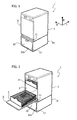
Figures 1 and 2 , with 1 is shown in the whole a dishwashing-machine like the one indicated in the introductive part of the present description, and in particular a free-standing dishwasher. Thedishwasher 1 has structure and functionality generally known , which will not be described in detail. With reference to the illustrated embodiment, it is here sufficient to explain that thedishwasher 1 has astationary structure 2 with awashtub 3 , in which are housed anupper basket 4 and alower basket 5 . Is possible to remove and insert thebaskets washtub 3 according to known feature, for example as described in the description introduction. In a preferred embodiment, the overall sizes of the dishwasher 1 (width W, height H and length or depth L) are the same already mentioned in the introduction of the present description. - The
dishwashing machine 1 has afront door 6, to access to thewashtub 3 and consequently to thebaskets stationary structure 2 of themachine 1, to be angularly displaceable about a substantially horizontal axis between a generally vertical position of closure, like inFig. 1 and a generally horizontal position of opening, like inFig. 2 . As said, in the open position of thedoor 6, thelower basket 5 can slide with its wheels, not shown in Figures, on the inner surface of the door (the so-called inner door): inFigure 2 thelower basket 5 is schematically represented indeed in an extracted position from thewashtub 3, resting on the inner side of thedoor 6. - The dishwasher1 is installed on a base, according to the present invention, indicated on the whole by 10.
- In one embodiment the dishwasher is simply placed on a top-
wall 11 of thebase 10 on which top are defined appropriated slots designed to partially receive standard adjustable dishwasher feet. In a different embodiment are provided specific means, of any known concept, to fasten the stationary structure of thedishwasher 1 to thebase 10, such as screws and nuts to be used in place of the said feet, which engage corresponding holes provided in thetop wall 11 of thebase 10. - The
base 10 has a strong enough structure to withstand the maximum weight of thedishwasher 1 in operative condition (for example with maximum loads of crockery and water). In a preferred embodiment, the supporting structure of thebase 10 is built with metallic material. - In a preferred embodiment the
base 10 has a width dimension W normally sized to support adishwasher 1, for example, of a width L indicatively comprised between 59.5 and 60 cm. Preferably, also the depth or length L of thebase 10 is dimensioned for adishwasher 1 size, for example, approximately comprised between 56.5 and 60 cm. It is evident, therefore, that the width L of thebase 10 has the same size of the door width of a common free-standing floor dishwasher like the one here shown with 1. The height of thebase 10 can be, for example, approximately comprised between 25 and 37 cm. - The
base 10 has afront passage 12 and is entirely hollow inside, in order to define a housing - not visible - for at least one movable support structure, generally designated with 20. In the installed condition, thebase 10 supports thedishwasher 1, with itsfront passage 12 which is located below thefront door 6 of thedishwasher 1. - The
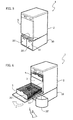
movable support structure 20 is constrained to thebase 10 to be displaceable through thefront passage 12 and is capable to assume an operative and inoperative position, as visible inFig 1-2 and4 , respectively. In the inoperative position, themovable support structure 20, is substantially inside the housing, and in the operative position, themovable support structure 20 is at least in part outside of the housing. As later better explained, according to the main invention characteristics, thebase 10 and themovable support structure 20, are configured so that when thestructure 20 is in its operative position, at least a part of themovable support structure 20 protrudes laterally beyond the width dimension (W) of thebase 10, particularly to be accessible from an user also when thefront door 6 of thedishwashing machine 1 is in its respective opening position substantially horizontal. The operating position of thesupport structure 20 is visible inFigure 4 . More particularly, in the exemplified embodiment inFigures 1-4 , thesupport structure 20 comprises a first part of thestructure 20a, which is constrained to thebase 10 in order to slide substantially linearly through thefront passage 12, between respective retracted (Figures 1 and 2 ) and extracted (figures 3 and 4 ) positions. The first part of thestructure 20a, which is configured in the example as a sliding drawer, supports in a guided way the second part of the structure, indicated with 20b, which can transversely move respect to the first part of thestructure 20a when the first part ofstructure 20a is in its respective extracted position respect to its housing on thebase 10. In the illustrated embodiment, also the second part of thestructure 20b, is configured substantially in a sliding drawer and is movable in a direction generally perpendicular to the direction of movements of the first part of thestructure 20a. - Comparing the
figures 3 and 4 it is possible to notice how, in this embodiment, the second part of thestructure 20b is displaceable between a respective retracted position (Figure 3 ) and a respective extracted one (Figure 4 ) with respect to the first part ofstructure 20a, when this last is extracted from the housing of thebase 10. - As clearly visible in
Figure 4 , in its extracted position, the second part of thestructure 20b protrudes laterally beyond the width dimension W of thebase 10, beyond of the first part of thestructure 20a and beyond thefront door 6 of thedishwasher 1. - The first part of the
structure 20a is here exemplified in a sliding drawer having a structure substantially box-shaped, preferably opened upwardly; however this is not essential for the purposes of the invention implementation: what matters is, in fact, that the first part of thestructure 20a is arranged in order to be able to be extracted and retracted respect to its relative housing of the base and support the second part of thestructure 20b. At most, therefore, the first part of the structure might simply include an horizontal base which moves in a linear way respect to the housing of the base, and on which base is supported the second part of the structure which moves transversally; for a such case, the above horizontal base is also preferably associated with a vertical front wall in order to close thefront passage 12 of the base 10 when the first part of thestructure 20a is in its retracted position. Same considerations are also valid for the second part of thestructure 20a , which is here exemplified in a sliding drawer, that is an upwardly opened box-shape structure, which can fulfill functions of container: more generally, the second part of thestructure 20b can be structured to exploit a support function for generic items, and in this case it may comprise a metal sheet not necessarily configured as a drawer. - The means to fix the first part of the
structure 20a to the base 10 may be of any known type, for example, common linear guides cooperating between the external longitudinal side of the part of thestructure 20a and the internal sidewalls of thebase 10, like the guide means usually used to constrain the linear sliding drawers with possible rolling elements. The same applies to the guide means used to constrain the second part of thestructure 20b to the first one 20a: in one embodiment, these guide means may be operatively assembled between the bottom of thepart 20a and the bottom of thepart 20b. - In a particularly, advantageous embodiment of the invention the second part of the
structure 20b can be completely displaceable between its respective retracted position and a first extracted position in corresponding of a first longitudinal side of the first part of thestructure 20a and is moreover displaceable between its respective retracted position and a second extracted position in corresponding of a second longitudinal side of the first part of thestructure 20a. A such solution is exemplified inFigure 4 , where with the solid line, in the second part of thestructure 20b, is represented in its first extracted position, while with the dashed line is represented its second extracted position. This feature is particularly advantageous for a user, both in view of a flexible installation of thedishwashing machine 1 and the base 10 (suppose a case in which the devices are in the household environment close to a wall: thestructure part 20b can be extracted in correspondence with the opposite side of the wall). - The advantages of the invention are evident in
Figure 4 . First of all the base 10 allows to raise from the floor thedishwasher 1 ensuring itself the user a general improvement of the ergonomic use ofmachine 1. The ergonomic advantages are further increased thanks to the possibility, allowed by the invention, to have access directly to thesupport structures 20 when themachine 1 is in its operative position, even despite a concurrent condition of the opening position of thedoor 6 of the machine. In this context, in a particularly advantageous embodiment, thestructure 20, and in particular itspart 20b, fulfills functions of container - or of support of a separate container - for the so-called wet-waste, and in particular garbage. As known, before being placed in the baskets of a dishwasher, from the crockery should be removed the residues of food: this operation can be performed directly at a kitchen sink, when this device is provided with a waste disposal unit, or using a garbage can or other container used for the collecting of wet-waste. - In the case of present invention, when the dishes are ready to be loaded in the
dishwasher 1, the machine's user does not have to do anything but carry thesupport structure 20 in the operating position ofFigure 4 , before opening thedoor 6 and extract theinterested basket structure 20b is freely accessible from above, laterally to thedoor 6, and therefore convenient to dump directly the eventual food scraps from the crockery. As mentioned, for this purpose, it's not strictly necessary that the second part of thestructure 20b is configured as a drawer, being able the same to include a simple frame for the support of a plastic bag or similar adapted to receive the wet waste. - Once loaded the dishwasher, the
baskets washtub 3 and thefront door 6 closed. Theparts Figure 1 . - In one embodiment like the illustrated one, the drawer of the second part of the
structure 20b has a containment volume less than the useful volume of the drawer of the first part of thestructure 20a. The difference in volume between the two parts in question can advantageously used to contain some frequently used items, particularly articles to use in combination with thedishwasher 1, such as packages of washing agents (liquid or powder detergent, soaps , regeneration salt, conditioner). Obviously nothing prevents to foresee also more second parts of thestructure 20b, for example with drawers to be opened transversely on one side or both sides of thestructure 20a, for example one for the wet waste and another one for different items, such as those mentioned above. - In its exemplified embodiment the
base 10 is configured as a distinct part respect to the support structure orcabinet 2 of thedishwasher 1, but in a different embodiment, not shown, the base 10 with its relative, movable,support structure 20 is integrated in said cabinet. In a such case, for example, the dishwasher machine base can also advantageously serve as a multipurpose container for some operational components of the dishwasher (a drain pump or a water conditioner), in a space not occupied by thesupport structure 20 when this is in its inoperative position. -
Figures 5 and 6 illustrate a second embodiment of the invention, wherein the support structure associated with thebase 10 comprises at least one swivel structure 20' which is articulated to the base 10 to perform at least one rotational movement about a substantially vertical axis, during the passage between the respective inoperative and operative positions. In this case, also, like seen inFig. 6 when the swivel structure 20' is in its operative extracted position, the same structure protrudes laterally beyond the width dimension W of the base and thedoor 6 of thedishwasher 1. The swivel structure 20 ', which is here configured like an angularly movable drawer, particularly with a plan profile substantially in the shape of a circular sector and can be fixed in a guided way to thebase 10 by a hinge of known conception, for example a hinge to a fixed fulcrum or pivot hinge movable, such as a hinge with roto-translational motion. - In the example of
Figures 5 and 6 , thebase 10 includes two different swivel structures 20', each of which is articulated to the base 10 substantially in correspondence with its respective longitudinal side of this last, in its front area, with the two structures 20' openable towards the two opposite sides of thedoor 6, one with clockwise rotation and the other one with a counterclockwise rotation. Such embodiment of structure 20' can be used to receive the wet waste and the other structure 20' to contain various items particularly to be used in combination with thedishwasher 1, as already exemplified above. It is also possible to provide a single rotatable structure 20' larger in place of the two illustrated, openable in order to protrude only by one side of thedoor 6. - When actuating the invention, to the
structure parts 20aparts - As previously mentioned, in one embodiment the
base 10 is configured as a distinct part respect to the cabinet of the dishwasher 1: such a base can then be combined with a normally intended dishwasher installed directly on the floor of a generic environment household. - According to a further aspect inventive in itself, is provided a dishwashing machine specifically designed for being used in combination with a base, not necessarily a
base 10 of the type previously described. - Normally the sewerage drain for household appliances (such as a wall attachment or associated with the pipe of a sink), are arranged at a height that requires making the drain pipe of a dishwasher in order to form a handle to a height average of between 40 and 80 cm from the floor.
- The presence of a base, however, has the effect of raising the whole dishwasher and the bottom of the relative washtub, to a quote approximately between 25 and 37 cm: in this situation, with a normal dishwasher, the handle of the drain pipe have to be at a height relatively close to the attack of the sewerage. This condition can cause siphoning during the machine operations. More particularly, it may happen that, at a loading of water in the washtub during a washing program, more or less important sewers depressions, caused for example by concomitant drains, performed by other household devices or sanitary, may occur. These depressions can drain the water already loaded in the washtub also in absence of activation of the dishwater pump drain.
- In order to avoid this kind of events, according to the above consideration autonomously inventive, a dishwasher is provided with an anti-siphoning arrangement, namely used when it is installed onto a support structure. But, when the dishwasher is installed directly onto the floor, the above arrangement is not used and its discharge hose can be arranged in the common way. In a preferred embodiment, the above anti-siphoning arrangement is equipped with a system to fasten the discharge hose to the cabinet where it is installed.
- An example is shown in
Figure 7 , where thedishwasher 1 is installed on ageneric support structure 10, not necessarily the same as the one described before. As usual, thedishwasher 1 has thedischarge hose 7 linked to therelated connection 8a on theback 8 of the machine, in the lower region. - The anti-siphoning arrangement includes an interstice, generally vertical oriented, defined substantially between a
lateral wall 2a of thecabinet 2 and theback 8 of themachine 1. For this purpose the said edge of the back is then turned down substantially like an "L" in order to be generally exposed in correspondence to a vertical recessof theback 8, not visible in the figure. The arrangement includes also anexit passage 9 for thedischarge hose 7, such a passage being defined in an upper region of thelateral wall 2a, generally closed to back 8. The interstice defined between thelateral wall 2a and theback 8 extends in height between the lower region ofback 8 and the said upper region of thelateral wall 2a, where thepassage 9 is. When thedishwasher 1 must be installed on abase 10, afterwards, thedischarge hose 7 is forced to pass through the mentioned interstice and to come out throughpassage 9, in a way where - in the installed condition of the machine - in correspondence topassage 9, thehose 7 results in a curving upstream of its exit edge 7a. This arrangement allows avoiding siphoning risks.Passage 9 can be considered on both thelateral walls 2a ofcabinet 2, whoseback 8 is equipped with 2 vertical nooks, each one in correspondence to the back edge of the twowalls 2a. - The passage (or passages) 9 could be closed by the related cap (or caps), or it (or they) could be partially pre-formed in the
walls 2a, for instance by means of localized circular weakening of the walls themselves, that can be opened just in case of need. - As per the above descriptions, the invention's main characteristics, as well as their advantages, are clear, namely represented by an improvement of the ergonomics of the dishwasher's use, and by the extended possibilities of using a related base. It is clear that the base and the dishwasher described in the previous sections for exemplification purposes can be subjected to numerous variants by a man skilled in the art without departing from the scopes of the invention as defined in the attached claims
- For instance, considering the configurations described in the
Figures 1-4 , the second part ofstructure 20b can be swivel along a vertical axis, like the case of structure 20' inFigure 6 . Of course, on the same part of structure 20' multiple swivel structures can be provided, or a combination with a sliding structure (like the 20b) and a swivel one (like the 20').
Claims (15)
- A dishwashing machine base (10) having a width dimension (W), a height dimension (H) and a length dimension (L), the base (10) defining a housing for at least a movable support structure (20; 20') and having a front passage (12), the movable support structure (20; 20') being constrained to the base (10) to be displaceable through the front passage (12) and being capable to assume an inoperative position, in which the movable support structure (20; 20') is substantially inside of the housing, and an operative position, in which the movable support structure (20; 20') is at least partly outside the housing,
wherein the base (10) is prearranged to support a dishwashing machine (1) in such a way that, in a respective condition of installation, the front passage (12) of the base (10) is under a front door (6) of the dishwashing machine (1),
wherein the base (10) and the movable support structure (20; 20') are configured in such a way that, in said condition of installation and with the movable support structure (20; 20') in its operative position, the movable support structure (20; 20') protrudes laterally beyond the width dimension (W) of the base (10), in particular to be accessible by a user also when the front door (6) of the dishwashing machine (1) is in a respective substantially horizontal position of opening. - The dishwashing machine base according to claim 1, wherein the movable support structure (20) comprises a first part of structure (20a) slidable substantially linearly through the front passage (12) between respective retracted and extracted positions with respect to the housing, the first part of structure (20a) supporting in a guided way a second part of structure (20b) which displaceable transversally with respect to the first part of structure (20a) when the first part of structure (20a) is in the respective extracted position with respect to the housing, the second part of structure (20b) being displaceable between a respective retracted position and a respective extracted position with respect to the first part of structure (20a), in its extracted position the second part of structure (20a) protruding laterally beyond the width dimension (W) of the base (20) and beyond a width dimension of the first part of structure (20a).
- The dishwashing machine base according to claim 1, wherein the support structure comprises at least one swivel structure (20') which is articulated to the base (10) to perform at least one rotation movement about a substantially vertical axis, during the passage between the respective inoperative and operative positions, in its operative position the swivel structure (20) protruding laterally beyond the width dimension (W) of the basement (10).
- The dishwashing machine base according to claim 2, wherein the second part of structure (20b) is constrained to the first part of structure (20a) to be slidable substantially linearly between the respective retracted and extracted positions with respect to the first part of structure (20a).
- The dishwashing machine base according to claim 4, wherein the second part of structure (20b) is displaceable between the respective retracted position and a first extracted position at a first longitudinal side of the first part of structure (20a) and is displaceable between the respective retracted position and a second extracted position at a second longitudinal side of the first part of structure (20a) which is opposite to the first longitudinal side.
- The dishwashing machine base according to claim 3, comprising one first said swivel structure (20') and one second said swivel structure (20'), each of which is articulated to the base (10) substantially at a respective longitudinal side of the base.
- The dishwashing machine base according to any one of the preceding claims, wherein the movable support structure (20) comprises a structure substantially configured as a slidable drawer (20a, 20b).
- The dishwashing machine base according to any one of the preceding claims, wherein the movable support structure (20; 20') comprises a structure substantially configured as an angularly movable drawer (20').
- The dishwashing machine base according to claim 2 or claim 5, wherein the second part of structure (20b) comprises a structure substantially configured as a slidable drawer.
- The dishwashing machine base according to any one of the preceding claims, characterized in that is defined by a cabinet (2) of the dishwashing machine (1).
- The dishwashing machine base according to any one of claims 1 to 10, characterized in that it is configured as a distinct part with respect to a cabinet (2) of the dishwashing machine (1).
- A dishwashing machine (1) with a washtub (3) and a front door (6) to have access to the washtub (3), the front door (6) having a width dimension (W) and being hinged at a lower region thereof to a stationary structure (2) of the machine (1), to be angularly displaceable about a substantially horizontal axis between a generally vertical position of closure and a generally horizontal position of opening,
wherein the machine (1) has a base (10) having a width dimension (W), a height dimension (H) and a length dimension (L), the base (10) defining a housing for at least one movable support structure (20; 20') and having a front passage (12) underneath the front door (6), the movable support structure (20; 20') being constrained to the base (10) to be displaceable through the front passage (12) and being capable to assume an inoperative position, in which the movable support structure (20; 20') is substantially inside of the housing, and an operative position, in which the movable support structure (20; 20') is at least partly outside the housing,
wherein the base (10) and the movable support structure (20; 20') are configured in such a way that, in its operative position, the movable support structure (20; 20') protrudes laterally beyond the width dimension (W) of the base (10) and beyond the width dimension (W) of the front door (6), to be accessible by a user also when the front door (6) of the dishwashing machine (1) is in the respective substantially horizontal position of opening. - The dishwashing machine according to claim 12, comprising a cabinet (2) and a discharge hose (7) that extends from a back (8) of the machine (1), wherein the machine (1) also comprises an anti-siphoning arrangement, including means for constraining an intermediate region of the of the discharge hose (7) to the cabinet (2).
- The dishwashing machine according to claim 13, wherein the anti-siphoning arrangement includes an interstice, defined substantially between a lateral wall (2a) of the cabinet (2) and the back (8) of the machine (1), and an exit passage (9) for the discharge hose (7) defined in an upper region of said lateral wall (2a) which is proximate to the back (8) of the machine (1), the interstice extending in height at least between a lower region of the back (8) of the machine (1) and said upper region of said lateral wall (2a).
- A dishwashing adapted to be installed on a base, particularly but not exclusively a base (10) according to one of claims 1 to 11, the machine (1) having a cabinet (2) and a discharge hose (7) that extends from a back (8) of the machine (1), wherein the machine (1) comprises an anti-siphoning arrangement including means for constraining an intermediate region of the discharge hose (7) to the cabinet (2), the anti-siphoning arrangement being designed for use when the machine (1) is installed on a base (10), where in particular the anti-siphoning arrangement includes an interstice, defined substantially between a lateral wall (2a) of the cabinet (2) and the back (8) of the machine (1), and an exit passage (9) for the discharge hose (7) defined in an upper region of said lateral wall (2a) that is proximate to the back (8) of the machine (1), the interstice extending in height at least between a lower region of the back (8) of the machine (1) and said upper region of said lateral wall (2a).
Applications Claiming Priority (1)
| Application Number | Priority Date | Filing Date | Title |
|---|---|---|---|
| IT001077A ITTO20121077A1 (en) | 2012-12-14 | 2012-12-14 | DISHWASHER MACHINE BASE AND DISHWASHER MACHINE |
Publications (3)
| Publication Number | Publication Date |
|---|---|
| EP2742845A2 true EP2742845A2 (en) | 2014-06-18 |
| EP2742845A3 EP2742845A3 (en) | 2014-09-03 |
| EP2742845B1 EP2742845B1 (en) | 2016-06-08 |
Family
ID=47683947
Family Applications (1)
| Application Number | Title | Priority Date | Filing Date |
|---|---|---|---|
| EP13196637.6A Not-in-force EP2742845B1 (en) | 2012-12-14 | 2013-12-11 | Dishwashing machine base and dishwashing machine |
Country Status (2)
| Country | Link |
|---|---|
| EP (1) | EP2742845B1 (en) |
| IT (1) | ITTO20121077A1 (en) |
Cited By (3)
| Publication number | Priority date | Publication date | Assignee | Title |
|---|---|---|---|---|
| EP3165665A1 (en) * | 2015-11-05 | 2017-05-10 | Wadrio Innovation ApS | Support for an appliance, such as a washer or dryer |
| CN112842200A (en) * | 2021-01-29 | 2021-05-28 | 上海明略人工智能(集团)有限公司 | Dish washing equipment and control method thereof |
| CN113558546A (en) * | 2021-06-17 | 2021-10-29 | 安徽工程大学 | Automatic wash dinner plate robot |
Citations (5)
| Publication number | Priority date | Publication date | Assignee | Title |
|---|---|---|---|---|
| DE1983863U (en) | 1968-01-27 | 1968-04-18 | Kempchen & Co Gmbh | ASBESTOS SEAL. |
| DE3212527A1 (en) | 1982-04-03 | 1983-10-13 | Wilhelm Dr.-Ing. 5340 Bad Honnef Lepper | Washing machine, washer/drier and laundry drier |
| DE9419048U1 (en) | 1994-01-28 | 1995-03-16 | Fragaria Ezio | Additional device on a washing machine |
| DE20302572U1 (en) | 2003-02-18 | 2003-04-24 | Hansen Nikolaus | Drawer unit forming the lower section of a washing machine cabinet |
| EP1462562A1 (en) | 2003-03-28 | 2004-09-29 | Merloni Elettrodomestici S.p.A. | A laundry washing and /or drying machine, in particular of the front loading type, with lower housing |
Family Cites Families (4)
| Publication number | Priority date | Publication date | Assignee | Title |
|---|---|---|---|---|
| DE19838630A1 (en) * | 1998-08-26 | 2000-03-02 | Benjamin Blumenschein | Base frame for domestic appliance has quadrangular support plate with edge strips which are bent downwards |
| JP2000139802A (en) * | 1998-11-10 | 2000-05-23 | Matsushita Electric Ind Co Ltd | Dishwasher |
| ITPN20000037A1 (en) * | 2000-06-07 | 2001-12-07 | Electrolux Zanussi Elettrodome | ERGONOMIC DISHWASHER |
| TR201104158A1 (en) * | 2011-04-28 | 2012-11-21 | Bsh Ev Aletleri̇ San. Ve Ti̇c. A.Ş. | Dishwasher with storage compartments for storing supplies |
-
2012
- 2012-12-14 IT IT001077A patent/ITTO20121077A1/en unknown
-
2013
- 2013-12-11 EP EP13196637.6A patent/EP2742845B1/en not_active Not-in-force
Patent Citations (5)
| Publication number | Priority date | Publication date | Assignee | Title |
|---|---|---|---|---|
| DE1983863U (en) | 1968-01-27 | 1968-04-18 | Kempchen & Co Gmbh | ASBESTOS SEAL. |
| DE3212527A1 (en) | 1982-04-03 | 1983-10-13 | Wilhelm Dr.-Ing. 5340 Bad Honnef Lepper | Washing machine, washer/drier and laundry drier |
| DE9419048U1 (en) | 1994-01-28 | 1995-03-16 | Fragaria Ezio | Additional device on a washing machine |
| DE20302572U1 (en) | 2003-02-18 | 2003-04-24 | Hansen Nikolaus | Drawer unit forming the lower section of a washing machine cabinet |
| EP1462562A1 (en) | 2003-03-28 | 2004-09-29 | Merloni Elettrodomestici S.p.A. | A laundry washing and /or drying machine, in particular of the front loading type, with lower housing |
Cited By (5)
| Publication number | Priority date | Publication date | Assignee | Title |
|---|---|---|---|---|
| EP3165665A1 (en) * | 2015-11-05 | 2017-05-10 | Wadrio Innovation ApS | Support for an appliance, such as a washer or dryer |
| WO2017077515A1 (en) | 2015-11-05 | 2017-05-11 | Wadrio Innovation Aps | Support for an appliance, such as a washer or dryer |
| CN112842200A (en) * | 2021-01-29 | 2021-05-28 | 上海明略人工智能(集团)有限公司 | Dish washing equipment and control method thereof |
| CN112842200B (en) * | 2021-01-29 | 2023-08-22 | 上海明略人工智能(集团)有限公司 | Dish washing equipment and dish washing equipment control method |
| CN113558546A (en) * | 2021-06-17 | 2021-10-29 | 安徽工程大学 | Automatic wash dinner plate robot |
Also Published As
| Publication number | Publication date |
|---|---|
| EP2742845B1 (en) | 2016-06-08 |
| ITTO20121077A1 (en) | 2014-06-15 |
| EP2742845A3 (en) | 2014-09-03 |
Similar Documents
| Publication | Publication Date | Title |
|---|---|---|
| KR101764460B1 (en) | Table top dishwasher | |
| US9187855B2 (en) | Modular laundry system with work surface | |
| US6997195B2 (en) | Ergonomic dishwashing machine | |
| US7587917B2 (en) | Modular laundry system with shelf module | |
| US20070151303A1 (en) | Modular laundry system with work surface having a functional element | |
| DK1393667T3 (en) | Dishwasher with a sealing system for the washroom closure | |
| CA2806386C (en) | Table top dishwasher | |
| EP2742845B1 (en) | Dishwashing machine base and dishwashing machine | |
| US2786730A (en) | Cabinet equipment | |
| RU2564230C2 (en) | Table dishwasher | |
| KR102393509B1 (en) | Rack for dishwasher and compact type dishwasher having the same | |
| US20090140619A1 (en) | Device for loading cutlery in dishwasher machines | |
| EP1451399A2 (en) | A work-top for household appliances | |
| US20170332879A1 (en) | Lower rack for a domestic dishwasher having a lower-rack raising means | |
| US20070151304A1 (en) | Modular laundry system with work surface having a functional insert | |
| WO2013109799A1 (en) | Dishwashing machine with movable basket holder device | |
| JP2007301129A (en) | Dishwasher | |
| KR102413327B1 (en) | Rack for dishwasher and compact type dishwasher having the same | |
| RU2713372C1 (en) | Home appliance with movable control panel and method of such device operation | |
| JPH08191998A (en) | Laundry unit | |
| EP1679402A3 (en) | Household appliance device for the washing | |
| EP2300655B1 (en) | An electrical household appliance for washing and/or drying textile articles | |
| US839992A (en) | Kitchen-cabinet. | |
| CN211417302U (en) | Movable multifunctional bathroom storage trolley | |
| WO2013182505A1 (en) | A household appliance |
Legal Events
| Date | Code | Title | Description |
|---|---|---|---|
| PUAI | Public reference made under article 153(3) epc to a published international application that has entered the european phase |
Free format text: ORIGINAL CODE: 0009012 |
|
| 17P | Request for examination filed |
Effective date: 20131211 |
|
| AK | Designated contracting states |
Kind code of ref document: A2 Designated state(s): AL AT BE BG CH CY CZ DE DK EE ES FI FR GB GR HR HU IE IS IT LI LT LU LV MC MK MT NL NO PL PT RO RS SE SI SK SM TR |
|
| AX | Request for extension of the european patent |
Extension state: BA ME |
|
| PUAL | Search report despatched |
Free format text: ORIGINAL CODE: 0009013 |
|
| AK | Designated contracting states |
Kind code of ref document: A3 Designated state(s): AL AT BE BG CH CY CZ DE DK EE ES FI FR GB GR HR HU IE IS IT LI LT LU LV MC MK MT NL NO PL PT RO RS SE SI SK SM TR |
|
| AX | Request for extension of the european patent |
Extension state: BA ME |
|
| RIC1 | Information provided on ipc code assigned before grant |
Ipc: A47L 15/42 20060101AFI20140730BHEP |
|
| R17P | Request for examination filed (corrected) |
Effective date: 20150303 |
|
| RBV | Designated contracting states (corrected) |
Designated state(s): AL AT BE BG CH CY CZ DE DK EE ES FI FR GB GR HR HU IE IS IT LI LT LU LV MC MK MT NL NO PL PT RO RS SE SI SK SM TR |
|
| GRAP | Despatch of communication of intention to grant a patent |
Free format text: ORIGINAL CODE: EPIDOSNIGR1 |
|
| RIC1 | Information provided on ipc code assigned before grant |
Ipc: A47L 15/42 20060101AFI20160316BHEP |
|
| INTG | Intention to grant announced |
Effective date: 20160401 |
|
| GRAS | Grant fee paid |
Free format text: ORIGINAL CODE: EPIDOSNIGR3 |
|
| GRAA | (expected) grant |
Free format text: ORIGINAL CODE: 0009210 |
|
| AK | Designated contracting states |
Kind code of ref document: B1 Designated state(s): AL AT BE BG CH CY CZ DE DK EE ES FI FR GB GR HR HU IE IS IT LI LT LU LV MC MK MT NL NO PL PT RO RS SE SI SK SM TR |
|
| REG | Reference to a national code |
Ref country code: GB Ref legal event code: FG4D |
|
| REG | Reference to a national code |
Ref country code: CH Ref legal event code: EP |
|
| REG | Reference to a national code |
Ref country code: IE Ref legal event code: FG4D |
|
| REG | Reference to a national code |
Ref country code: AT Ref legal event code: REF Ref document number: 804617 Country of ref document: AT Kind code of ref document: T Effective date: 20160715 |
|
| REG | Reference to a national code |
Ref country code: DE Ref legal event code: R096 Ref document number: 602013008356 Country of ref document: DE |
|
| REG | Reference to a national code |
Ref country code: LT Ref legal event code: MG4D |
|
| REG | Reference to a national code |
Ref country code: NL Ref legal event code: MP Effective date: 20160608 |
|
| PG25 | Lapsed in a contracting state [announced via postgrant information from national office to epo] |
Ref country code: LT Free format text: LAPSE BECAUSE OF FAILURE TO SUBMIT A TRANSLATION OF THE DESCRIPTION OR TO PAY THE FEE WITHIN THE PRESCRIBED TIME-LIMIT Effective date: 20160608 Ref country code: NO Free format text: LAPSE BECAUSE OF FAILURE TO SUBMIT A TRANSLATION OF THE DESCRIPTION OR TO PAY THE FEE WITHIN THE PRESCRIBED TIME-LIMIT Effective date: 20160908 Ref country code: FI Free format text: LAPSE BECAUSE OF FAILURE TO SUBMIT A TRANSLATION OF THE DESCRIPTION OR TO PAY THE FEE WITHIN THE PRESCRIBED TIME-LIMIT Effective date: 20160608 |
|
| REG | Reference to a national code |
Ref country code: FR Ref legal event code: PLFP Year of fee payment: 4 |
|
| REG | Reference to a national code |
Ref country code: AT Ref legal event code: MK05 Ref document number: 804617 Country of ref document: AT Kind code of ref document: T Effective date: 20160608 |
|
| PG25 | Lapsed in a contracting state [announced via postgrant information from national office to epo] |
Ref country code: RS Free format text: LAPSE BECAUSE OF FAILURE TO SUBMIT A TRANSLATION OF THE DESCRIPTION OR TO PAY THE FEE WITHIN THE PRESCRIBED TIME-LIMIT Effective date: 20160608 Ref country code: LV Free format text: LAPSE BECAUSE OF FAILURE TO SUBMIT A TRANSLATION OF THE DESCRIPTION OR TO PAY THE FEE WITHIN THE PRESCRIBED TIME-LIMIT Effective date: 20160608 Ref country code: NL Free format text: LAPSE BECAUSE OF FAILURE TO SUBMIT A TRANSLATION OF THE DESCRIPTION OR TO PAY THE FEE WITHIN THE PRESCRIBED TIME-LIMIT Effective date: 20160608 Ref country code: HR Free format text: LAPSE BECAUSE OF FAILURE TO SUBMIT A TRANSLATION OF THE DESCRIPTION OR TO PAY THE FEE WITHIN THE PRESCRIBED TIME-LIMIT Effective date: 20160608 Ref country code: GR Free format text: LAPSE BECAUSE OF FAILURE TO SUBMIT A TRANSLATION OF THE DESCRIPTION OR TO PAY THE FEE WITHIN THE PRESCRIBED TIME-LIMIT Effective date: 20160909 Ref country code: ES Free format text: LAPSE BECAUSE OF FAILURE TO SUBMIT A TRANSLATION OF THE DESCRIPTION OR TO PAY THE FEE WITHIN THE PRESCRIBED TIME-LIMIT Effective date: 20160608 Ref country code: SE Free format text: LAPSE BECAUSE OF FAILURE TO SUBMIT A TRANSLATION OF THE DESCRIPTION OR TO PAY THE FEE WITHIN THE PRESCRIBED TIME-LIMIT Effective date: 20160608 |
|
| PG25 | Lapsed in a contracting state [announced via postgrant information from national office to epo] |
Ref country code: RO Free format text: LAPSE BECAUSE OF FAILURE TO SUBMIT A TRANSLATION OF THE DESCRIPTION OR TO PAY THE FEE WITHIN THE PRESCRIBED TIME-LIMIT Effective date: 20160608 Ref country code: CZ Free format text: LAPSE BECAUSE OF FAILURE TO SUBMIT A TRANSLATION OF THE DESCRIPTION OR TO PAY THE FEE WITHIN THE PRESCRIBED TIME-LIMIT Effective date: 20160608 Ref country code: IS Free format text: LAPSE BECAUSE OF FAILURE TO SUBMIT A TRANSLATION OF THE DESCRIPTION OR TO PAY THE FEE WITHIN THE PRESCRIBED TIME-LIMIT Effective date: 20161008 Ref country code: SK Free format text: LAPSE BECAUSE OF FAILURE TO SUBMIT A TRANSLATION OF THE DESCRIPTION OR TO PAY THE FEE WITHIN THE PRESCRIBED TIME-LIMIT Effective date: 20160608 Ref country code: EE Free format text: LAPSE BECAUSE OF FAILURE TO SUBMIT A TRANSLATION OF THE DESCRIPTION OR TO PAY THE FEE WITHIN THE PRESCRIBED TIME-LIMIT Effective date: 20160608 |
|
| RAP2 | Party data changed (patent owner data changed or rights of a patent transferred) |
Owner name: WHIRLPOOL EMEA S.P.A |
|
| PG25 | Lapsed in a contracting state [announced via postgrant information from national office to epo] |
Ref country code: PL Free format text: LAPSE BECAUSE OF FAILURE TO SUBMIT A TRANSLATION OF THE DESCRIPTION OR TO PAY THE FEE WITHIN THE PRESCRIBED TIME-LIMIT Effective date: 20160608 Ref country code: SM Free format text: LAPSE BECAUSE OF FAILURE TO SUBMIT A TRANSLATION OF THE DESCRIPTION OR TO PAY THE FEE WITHIN THE PRESCRIBED TIME-LIMIT Effective date: 20160608 Ref country code: AT Free format text: LAPSE BECAUSE OF FAILURE TO SUBMIT A TRANSLATION OF THE DESCRIPTION OR TO PAY THE FEE WITHIN THE PRESCRIBED TIME-LIMIT Effective date: 20160608 Ref country code: PT Free format text: LAPSE BECAUSE OF FAILURE TO SUBMIT A TRANSLATION OF THE DESCRIPTION OR TO PAY THE FEE WITHIN THE PRESCRIBED TIME-LIMIT Effective date: 20161010 Ref country code: BE Free format text: LAPSE BECAUSE OF FAILURE TO SUBMIT A TRANSLATION OF THE DESCRIPTION OR TO PAY THE FEE WITHIN THE PRESCRIBED TIME-LIMIT Effective date: 20160608 |
|
| REG | Reference to a national code |
Ref country code: DE Ref legal event code: R097 Ref document number: 602013008356 Country of ref document: DE |
|
| PLBE | No opposition filed within time limit |
Free format text: ORIGINAL CODE: 0009261 |
|
| STAA | Information on the status of an ep patent application or granted ep patent |
Free format text: STATUS: NO OPPOSITION FILED WITHIN TIME LIMIT |
|
| 26N | No opposition filed |
Effective date: 20170309 |
|
| PG25 | Lapsed in a contracting state [announced via postgrant information from national office to epo] |
Ref country code: SI Free format text: LAPSE BECAUSE OF FAILURE TO SUBMIT A TRANSLATION OF THE DESCRIPTION OR TO PAY THE FEE WITHIN THE PRESCRIBED TIME-LIMIT Effective date: 20160608 Ref country code: DK Free format text: LAPSE BECAUSE OF FAILURE TO SUBMIT A TRANSLATION OF THE DESCRIPTION OR TO PAY THE FEE WITHIN THE PRESCRIBED TIME-LIMIT Effective date: 20160608 |
|
| REG | Reference to a national code |
Ref country code: CH Ref legal event code: PL |
|
| PG25 | Lapsed in a contracting state [announced via postgrant information from national office to epo] |
Ref country code: MC Free format text: LAPSE BECAUSE OF FAILURE TO SUBMIT A TRANSLATION OF THE DESCRIPTION OR TO PAY THE FEE WITHIN THE PRESCRIBED TIME-LIMIT Effective date: 20160608 |
|
| REG | Reference to a national code |
Ref country code: IE Ref legal event code: MM4A |
|
| PG25 | Lapsed in a contracting state [announced via postgrant information from national office to epo] |
Ref country code: LI Free format text: LAPSE BECAUSE OF NON-PAYMENT OF DUE FEES Effective date: 20161231 Ref country code: CH Free format text: LAPSE BECAUSE OF NON-PAYMENT OF DUE FEES Effective date: 20161231 Ref country code: LU Free format text: LAPSE BECAUSE OF NON-PAYMENT OF DUE FEES Effective date: 20161211 |
|
| REG | Reference to a national code |
Ref country code: FR Ref legal event code: PLFP Year of fee payment: 5 |
|
| PG25 | Lapsed in a contracting state [announced via postgrant information from national office to epo] |
Ref country code: IE Free format text: LAPSE BECAUSE OF NON-PAYMENT OF DUE FEES Effective date: 20161211 |
|
| PG25 | Lapsed in a contracting state [announced via postgrant information from national office to epo] |
Ref country code: HU Free format text: LAPSE BECAUSE OF FAILURE TO SUBMIT A TRANSLATION OF THE DESCRIPTION OR TO PAY THE FEE WITHIN THE PRESCRIBED TIME-LIMIT; INVALID AB INITIO Effective date: 20131211 |
|
| PG25 | Lapsed in a contracting state [announced via postgrant information from national office to epo] |
Ref country code: MK Free format text: LAPSE BECAUSE OF FAILURE TO SUBMIT A TRANSLATION OF THE DESCRIPTION OR TO PAY THE FEE WITHIN THE PRESCRIBED TIME-LIMIT Effective date: 20160608 Ref country code: CY Free format text: LAPSE BECAUSE OF FAILURE TO SUBMIT A TRANSLATION OF THE DESCRIPTION OR TO PAY THE FEE WITHIN THE PRESCRIBED TIME-LIMIT Effective date: 20160608 |
|
| PG25 | Lapsed in a contracting state [announced via postgrant information from national office to epo] |
Ref country code: BG Free format text: LAPSE BECAUSE OF FAILURE TO SUBMIT A TRANSLATION OF THE DESCRIPTION OR TO PAY THE FEE WITHIN THE PRESCRIBED TIME-LIMIT Effective date: 20160608 |
|
| PG25 | Lapsed in a contracting state [announced via postgrant information from national office to epo] |
Ref country code: MT Free format text: LAPSE BECAUSE OF NON-PAYMENT OF DUE FEES Effective date: 20161211 |
|
| PG25 | Lapsed in a contracting state [announced via postgrant information from national office to epo] |
Ref country code: AL Free format text: LAPSE BECAUSE OF FAILURE TO SUBMIT A TRANSLATION OF THE DESCRIPTION OR TO PAY THE FEE WITHIN THE PRESCRIBED TIME-LIMIT Effective date: 20160608 Ref country code: TR Free format text: LAPSE BECAUSE OF FAILURE TO SUBMIT A TRANSLATION OF THE DESCRIPTION OR TO PAY THE FEE WITHIN THE PRESCRIBED TIME-LIMIT Effective date: 20160608 |
|
| PGFP | Annual fee paid to national office [announced via postgrant information from national office to epo] |
Ref country code: DE Payment date: 20191126 Year of fee payment: 7 |
|
| PGFP | Annual fee paid to national office [announced via postgrant information from national office to epo] |
Ref country code: FR Payment date: 20191115 Year of fee payment: 7 Ref country code: IT Payment date: 20191209 Year of fee payment: 7 |
|
| PGFP | Annual fee paid to national office [announced via postgrant information from national office to epo] |
Ref country code: GB Payment date: 20191213 Year of fee payment: 7 |
|
| REG | Reference to a national code |
Ref country code: DE Ref legal event code: R119 Ref document number: 602013008356 Country of ref document: DE |
|
| GBPC | Gb: european patent ceased through non-payment of renewal fee |
Effective date: 20201211 |
|
| PG25 | Lapsed in a contracting state [announced via postgrant information from national office to epo] |
Ref country code: FR Free format text: LAPSE BECAUSE OF NON-PAYMENT OF DUE FEES Effective date: 20201231 Ref country code: IT Free format text: LAPSE BECAUSE OF NON-PAYMENT OF DUE FEES Effective date: 20201211 |
|
| PG25 | Lapsed in a contracting state [announced via postgrant information from national office to epo] |
Ref country code: DE Free format text: LAPSE BECAUSE OF NON-PAYMENT OF DUE FEES Effective date: 20210701 Ref country code: GB Free format text: LAPSE BECAUSE OF NON-PAYMENT OF DUE FEES Effective date: 20201211 |