EP2742787B1 - Frame for a cereal seeder and cereal seeder that includes said frame - Google Patents
Frame for a cereal seeder and cereal seeder that includes said frame Download PDFInfo
- Publication number
- EP2742787B1 EP2742787B1 EP13193607.2A EP13193607A EP2742787B1 EP 2742787 B1 EP2742787 B1 EP 2742787B1 EP 13193607 A EP13193607 A EP 13193607A EP 2742787 B1 EP2742787 B1 EP 2742787B1
- Authority
- EP
- European Patent Office
- Prior art keywords
- chassis
- frame
- seeder
- arms
- sowing
- Prior art date
- Legal status (The legal status is an assumption and is not a legal conclusion. Google has not performed a legal analysis and makes no representation as to the accuracy of the status listed.)
- Active
Links
Images



Classifications
-
- A—HUMAN NECESSITIES
- A01—AGRICULTURE; FORESTRY; ANIMAL HUSBANDRY; HUNTING; TRAPPING; FISHING
- A01B—SOIL WORKING IN AGRICULTURE OR FORESTRY; PARTS, DETAILS, OR ACCESSORIES OF AGRICULTURAL MACHINES OR IMPLEMENTS, IN GENERAL
- A01B63/00—Lifting or adjusting devices or arrangements for agricultural machines or implements
- A01B63/14—Lifting or adjusting devices or arrangements for agricultural machines or implements for implements drawn by animals or tractors
- A01B63/24—Tools or tool-holders adjustable relatively to the frame
- A01B63/245—Tools or tool-holders adjustable relatively to the frame laterally adjustable
-
- A—HUMAN NECESSITIES
- A01—AGRICULTURE; FORESTRY; ANIMAL HUSBANDRY; HUNTING; TRAPPING; FISHING
- A01C—PLANTING; SOWING; FERTILISING
- A01C7/00—Sowing
- A01C7/20—Parts of seeders for conducting and depositing seed
-
- A—HUMAN NECESSITIES
- A01—AGRICULTURE; FORESTRY; ANIMAL HUSBANDRY; HUNTING; TRAPPING; FISHING
- A01B—SOIL WORKING IN AGRICULTURE OR FORESTRY; PARTS, DETAILS, OR ACCESSORIES OF AGRICULTURAL MACHINES OR IMPLEMENTS, IN GENERAL
- A01B73/00—Means or arrangements to facilitate transportation of agricultural machines or implements, e.g. folding frames to reduce overall width
-
- A—HUMAN NECESSITIES
- A01—AGRICULTURE; FORESTRY; ANIMAL HUSBANDRY; HUNTING; TRAPPING; FISHING
- A01C—PLANTING; SOWING; FERTILISING
- A01C7/00—Sowing
- A01C7/08—Broadcast seeders; Seeders depositing seeds in rows
- A01C7/087—Tramlining
-
- A—HUMAN NECESSITIES
- A01—AGRICULTURE; FORESTRY; ANIMAL HUSBANDRY; HUNTING; TRAPPING; FISHING
- A01C—PLANTING; SOWING; FERTILISING
- A01C7/00—Sowing
- A01C7/20—Parts of seeders for conducting and depositing seed
- A01C7/201—Mounting of the seeding tools
-
- A—HUMAN NECESSITIES
- A01—AGRICULTURE; FORESTRY; ANIMAL HUSBANDRY; HUNTING; TRAPPING; FISHING
- A01C—PLANTING; SOWING; FERTILISING
- A01C7/00—Sowing
- A01C7/20—Parts of seeders for conducting and depositing seed
- A01C7/206—Seed pipes
-
- A—HUMAN NECESSITIES
- A01—AGRICULTURE; FORESTRY; ANIMAL HUSBANDRY; HUNTING; TRAPPING; FISHING
- A01C—PLANTING; SOWING; FERTILISING
- A01C7/00—Sowing
- A01C7/20—Parts of seeders for conducting and depositing seed
- A01C7/208—Chassis; Coupling means to a tractor or the like; Lifting means; Side markers
-
- A—HUMAN NECESSITIES
- A01—AGRICULTURE; FORESTRY; ANIMAL HUSBANDRY; HUNTING; TRAPPING; FISHING
- A01B—SOIL WORKING IN AGRICULTURE OR FORESTRY; PARTS, DETAILS, OR ACCESSORIES OF AGRICULTURAL MACHINES OR IMPLEMENTS, IN GENERAL
- A01B63/00—Lifting or adjusting devices or arrangements for agricultural machines or implements
- A01B63/002—Devices for adjusting or regulating the position of tools or wheels
- A01B63/004—Lateral adjustment of tools
-
- A—HUMAN NECESSITIES
- A01—AGRICULTURE; FORESTRY; ANIMAL HUSBANDRY; HUNTING; TRAPPING; FISHING
- A01C—PLANTING; SOWING; FERTILISING
- A01C7/00—Sowing
- A01C7/20—Parts of seeders for conducting and depositing seed
- A01C7/201—Mounting of the seeding tools
- A01C7/203—Mounting of the seeding tools comprising depth regulation means
Definitions
- the present invention relates to a frame for a cereal seeder of the type of those where the seeds are distributed from the hopper to the furrow by gravity and to a cereal seeder including said frame which makes it possible to modify the working width of the machine at the same time guaranteeing a suitable width for road transport.
- Seeders are known wherein the seeds are distributed to the furrow by gravity. These seeders are suitable for the sowing of seeds of cereals at a steady "flow" and for this have plastic tubes that channel the seeds from the dispensing hopper to each one of the sowing elements provided in the frame chassis.
- Said cereal seeders have numerous advantages with respect to another type of seeders that use pneumatic seed distribution systems.
- the gravity distribution system is less complex than the pneumatic and requires less energy consumption and less maintenance.
- the gravity distribution system reduces seed blockages and facilitates visual control of the seed.
- Document DE3627801 discloses one of these existing cereal seeders.
- the objective of the present invention is to resolve said drawbacks mentioned, developing a frame for a cereal seeder which allows expanding the working width of said seeder.
- the present invention provides a frame for a cereal seeder of the type of those where the seeds are distributed from the hopper to the furrow by gravity, comprising a chassis provided with a plurality of sowing elements of said seeder, said chassis comprising a plurality of support arms of said sowing elements, said support arms being disposed substantially parallel in a same horizontal plane, the sowing elements of said support arms determining the sowing lines of said seeder, and it is characterized in that said arms comprising at least one telescopic portion susceptible of being horizontally extended from a transport position to an expanded working position and in that said frame includes at least one fluid-dynamic cylinder to actuate said telescopic portion.
- the frame of the present invention has the advantage that it makes it possible to modify the working width "A" of the machine (greater number of sowing rows per run), at the same time guaranteeing a transport width "D" not greater than three metres.
- sowing elements are disposed distributed in several support arms and said arms have an extendable portion, it is possible to gain distance between the sowing elements of a same arm to allow the folding of an extendable portion within the maximum transport width of three metres.
- said chassis comprises at least four support arms of said sowing elements disposed substantially parallel in a same horizontal plane, each one of said four arms including at least one portion susceptible of being horizontally extended.
- said frame comprises at least two chassis which are disposed longitudinally aligned, the free end of the arms of each one of said two chassis including at least one portion susceptible of being horizontally extended.
- Each one of said chassis comprises at least four support arms of the sowing elements disposed substantially parallel in a same plane.
- the extended portions of said chassis are configured to determine in an extended position a working width "A" equal to or greater than 4 m.
- This working width makes it possible to include between 23 and 25 sowing elements varying the distance "d" between sowing rows.
- said frame comprises first seed dispensing means disposed to feed the arms of the front part of said chassis and second seed dispensing means disposed to feed the arms of the rear part of the same chassis.
- said first dispensing means are associated to a first seed dispensing hopper of said seeder and said second dispensing means are associated to a second seed dispensing hopper of the same seeder, and advantageously, each one of said first or second dispensing means include a nozzle bar and tubes for the falling of the seeds from the nozzles of said bar to the sowing elements of the arms.
- the chassis of the frame is articulately joined to a subframe through a parallelogram mechanism comprising a first connecting rod joined by one end to said subframe and by its other end to an arm of the front part of said chassis and a second connecting rod joined by one end to said same subframe and by its other end to an arm of the rear part of said chassis.
- said frame comprising two aligned chassis, said frame comprising two parallelogram mechanisms for each one of said chassis.
- said frame comprises means to regulate the height of said chassis, said regulation means including a worm provided on a tie rod which is articulately joined to said chassis.
- the present invention provides a cereal seeder of the type of those where the seeds are distributed to the furrow by gravity, which is characterized in that it includes a frame such as that claimed.
- the seeder of the present invention has the advantage that it has a highly expanded working width, and is, in turn, of very light construction, so that it can be transported by a tractor with little power, unlike what happens with pneumatic seeders.
- said seeder comprises at least one seed dispensing hopper the length of which is substantially equal to the length of said chassis or set of two chassis in their folded transport position.
- the seed can be efficiently distributed to all the sowing elements in the extended working position of the frame.
- said seeder comprises two seed dispensing hoppers each associated to seed dispensing means of said frame and, preferably, the rotation shafts of the dispensing means of said two hoppers are actuated by a same drive chain which is linked to the drive mechanism of a wheel of said seeder.
- FIG 1 shows an embodiment of the chassis including two longitudinally aligned chassis 2a, 2b which are each provided with four support arms 3 of the sowing elements 4.
- the support arms 3 of the two chassis 2a, 2b are disposed substantially parallel in a same horizontal plane and each have a telescopic portion 3a at their free ends susceptible of being horizontally extended by the action of fluid-dynamic cylinders 5 of the chassis..
- the telescopic portions 3a are extended so that the sowing elements 4a situated in said portions 3a are displaced acquiring the desired working width "A".
- the seeds are distributed to the sowing elements 4a thanks to conduits 6 which channel the seeds from nozzles 7 situated in nozzle bars 8 associated to two seed distribution hoppers 9.
- One of said hoppers 9a feeds the sowing elements 4 of the arms 3 of the front part of the frame 1 and the other hopper 9b feeds the sowing elements 4 of the rear part.
- Figure 6 shows a side view of a seeder 10 including the frame 1 of figure 1 .
- the two seed dispensing hoppers 9a, 9b associated to the nozzle bars 8 can be observed, which are each disposed just below the rotation shaft 16 of the dispensing means of the two hoppers 9a,9b.
- the shafts 16 of each hopper 9a, 9b are actuated by the same drive chain (not represented) which are linked to the wheel drive mechanism of said seeder 10.
- Figures 3 and 4 show in detail the length of the two nozzle bars 8 associated to the hoppers 9a, 9b, as well as the seed conduits 6 to the sowing elements 4a of the unfolding portions 3a of the arms 3.
- Figure 3 shows the working width acquired by the frame 1 provided with 25 sowing elements 4 with a distance "d" between rows of 160 mm which is suitable for the sowing of cereal.
- the 25 sowing elements 4 are disposed distributed in the support arms 3 of the two chassis 2a,2b so that the sowing elements 4 of a same arm 3 keep the sufficient distance to allow the folding of the unfolding portion 3a within the maximum transport width "D" of three metres.
- Figure 5 shows the frame 1 in its folded transport position with the portions 3a retracted.
- the chassis is floating and has height regulation means to control the sowing depth with greater accuracy.
- each one of the chassis 2a, 2b of the frame 1 is articulately joined to a subframe through two parallelogram mechanisms 11 each one including a first connecting rod 12 joined by one end to said subframe and by its other end to an arm 3 of the front part of the chassis 2 and a second connecting rod 13 joined by one end to said subframe and by its end to an arm 3 of the rear part of the same chassis 2a,2b.
- Figure 4 shows a side view of the frame 1 wherein said parallelogram mechanism 11 of one of the chassis 2b is observed.
- a worm 14 has been provided which is joined to a tie rod 15 of the chassis 2a,2b.
- this tie rod 15 is articulately joined to the chassis 2a,2b, allowing that, on threading the worm 14, the floating chassis rises actuated by the tie rod 15.
- a cereal seeder is obtained of light construction which makes it possible to sow the largest number of rows per run, it is very simple and versatile and allows a very accurate control of sowing depth.
Landscapes
- Life Sciences & Earth Sciences (AREA)
- Soil Sciences (AREA)
- Environmental Sciences (AREA)
- Engineering & Computer Science (AREA)
- Mechanical Engineering (AREA)
- Zoology (AREA)
- Sowing (AREA)
Description
- The present invention relates to a frame for a cereal seeder of the type of those where the seeds are distributed from the hopper to the furrow by gravity and to a cereal seeder including said frame which makes it possible to modify the working width of the machine at the same time guaranteeing a suitable width for road transport.
- The market demands increasingly wide seeders and with the possibility of sowing a larger number of sowing lines or rows in one run. However, road transport requirements limit the machine's width in the transport position to a maximum of three metres.
- Seeders are known wherein the seeds are distributed to the furrow by gravity. These seeders are suitable for the sowing of seeds of cereals at a steady "flow" and for this have plastic tubes that channel the seeds from the dispensing hopper to each one of the sowing elements provided in the frame chassis.
- Said cereal seeders have numerous advantages with respect to another type of seeders that use pneumatic seed distribution systems. For example, the gravity distribution system is less complex than the pneumatic and requires less energy consumption and less maintenance. Furthermore, the gravity distribution system reduces seed blockages and facilitates visual control of the seed. Document
DE3627801 discloses one of these existing cereal seeders. - However, the existing cereal seeders as the one disclosed in document
DE3627801 have the drawback that their working width is limited to the road transport width, since the cereal sowing requires a greatly reduced distance between sowing elements which leaves very little margin for the application of chassis folding and unfolding systems used in another type of seeders designed for "single grain" sowing. - In particular, it has been observed that, in the cereal seeders, the distance between sowing elements of a same chassis is too reduced to allow the extended sowing elements to be retracted within the maximum three metres width for transport. On the other hand, it has been observed that a possible expansion of the number of sowing elements entails seed transport problems, since the gravity distribution system is not as efficient as the pneumatic.
- The objective of the present invention is to resolve said drawbacks mentioned, developing a frame for a cereal seeder which allows expanding the working width of said seeder.
- In accordance with this objective, according to a first aspect the present invention provides a frame for a cereal seeder of the type of those where the seeds are distributed from the hopper to the furrow by gravity, comprising a chassis provided with a plurality of sowing elements of said seeder, said chassis comprising a plurality of support arms of said sowing elements, said support arms being disposed substantially parallel in a same horizontal plane, the sowing elements of said support arms determining the sowing lines of said seeder, and it is characterized in that said arms comprising at least one telescopic portion susceptible of being horizontally extended from a transport position to an expanded working position and in that said frame includes at least one fluid-dynamic cylinder to actuate said telescopic portion.
- The frame of the present invention has the advantage that it makes it possible to modify the working width "A" of the machine (greater number of sowing rows per run), at the same time guaranteeing a transport width "D" not greater than three metres.
- Indeed, as the sowing elements are disposed distributed in several support arms and said arms have an extendable portion, it is possible to gain distance between the sowing elements of a same arm to allow the folding of an extendable portion within the maximum transport width of three metres.
- In this way, a seeder is obtained of those that allow sowing cereal with the required distance "d" between sowing lines or rows, being possible to acquire tat the same time a working width "A" equal or greater than four metres in the extended position of said frame, or a width "D" of three metres for transport (folded position of the frame).
- According to a preferred embodiment, said chassis comprises at least four support arms of said sowing elements disposed substantially parallel in a same horizontal plane, each one of said four arms including at least one portion susceptible of being horizontally extended.
- Preferably, according to the same preferred embodiment, said frame comprises at least two chassis which are disposed longitudinally aligned, the free end of the arms of each one of said two chassis including at least one portion susceptible of being horizontally extended. Each one of said chassis comprises at least four support arms of the sowing elements disposed substantially parallel in a same plane.
- It has been observed that, with these two chassis being disposed aligned, the frame better adapts to the irregularities of the land where the sowing is carried out.
- Again advantageously, the extended portions of said chassis are configured to determine in an extended position a working width "A" equal to or greater than 4 m. This working width makes it possible to include between 23 and 25 sowing elements varying the distance "d" between sowing rows.
- According to the same preferred embodiment, said frame comprises first seed dispensing means disposed to feed the arms of the front part of said chassis and second seed dispensing means disposed to feed the arms of the rear part of the same chassis.
- In this way, it has been observed that they avoid possible transport problems of the seeds produced by expanding the working width of the seeder.
- Preferably, said first dispensing means are associated to a first seed dispensing hopper of said seeder and said second dispensing means are associated to a second seed dispensing hopper of the same seeder, and advantageously, each one of said first or second dispensing means include a nozzle bar and tubes for the falling of the seeds from the nozzles of said bar to the sowing elements of the arms.
- According to the same preferred embodiment, the chassis of the frame is articulately joined to a subframe through a parallelogram mechanism comprising a first connecting rod joined by one end to said subframe and by its other end to an arm of the front part of said chassis and a second connecting rod joined by one end to said same subframe and by its other end to an arm of the rear part of said chassis.
- According to the preferred embodiment of the invention comprising two aligned chassis, said frame comprising two parallelogram mechanisms for each one of said chassis.
Preferably, said frame comprises means to regulate the height of said chassis, said regulation means including a worm provided on a tie rod which is articulately joined to said chassis. - Thanks to said parallelogram mechanisms and to the height regulation worm, a floating chassis is obtained which allows a very precise control of the sowing depth.
- In accordance with a second aspect, the present invention provides a cereal seeder of the type of those where the seeds are distributed to the furrow by gravity, which is characterized in that it includes a frame such as that claimed.
- The seeder of the present invention has the advantage that it has a highly expanded working width, and is, in turn, of very light construction, so that it can be transported by a tractor with little power, unlike what happens with pneumatic seeders.
- Preferably, said seeder comprises at least one seed dispensing hopper the length of which is substantially equal to the length of said chassis or set of two chassis in their folded transport position.
- In this way, the seed can be efficiently distributed to all the sowing elements in the extended working position of the frame.
- Advantageously, said seeder comprises two seed dispensing hoppers each associated to seed dispensing means of said frame and, preferably, the rotation shafts of the dispensing means of said two hoppers are actuated by a same drive chain which is linked to the drive mechanism of a wheel of said seeder.
- For a better understanding of all that disclosed, drawings are attached wherein, diagrammatically and only as a non-limitative example, a practical embodiment is represented.
- In these drawings,
-
Figure 1 is a perspective view of a preferred embodiment of the chassis of the present invention including four support arms of sowing elements, in an extended working position. -
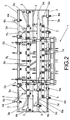
Figure 2 is a plan view of the frame offigure 1 in an extended working position. In thisfigure 2 the seed dispensing means of the front and rear arms have been represented. -
Figure 3 is a front view of the frame represented infigure 2 , wherein the working width is observed. -
Figure 4 is a side view of the same frame represented infigure 2 . -
Figure 5 is a front view of the frame represented infigure 2 but in the folded transport position. -
Figure 6 is a sectional view of a cereal seeder provided with the frame of the embodiment offigure 1 and of two dispensing hoppers. -
Figure 7 shows a detail offigure 6 wherein the height control worm of the frame can be observed. - Below, a preferred embodiment is described of a frame of the present invention making reference to said figures.
-
Figure 1 shows an embodiment of the chassis including two longitudinally alignedchassis support arms 3 of thesowing elements 4. - As can be seen in
figure 1 , thesupport arms 3 of the twochassis telescopic portion 3a at their free ends susceptible of being horizontally extended by the action of fluid-dynamic cylinders 5 of the chassis.. - In the working position of the chassis shown by
figures 1 to 3 , thetelescopic portions 3a are extended so that thesowing elements 4a situated in saidportions 3a are displaced acquiring the desired working width "A". In this extended position, the seeds are distributed to thesowing elements 4a thanks toconduits 6 which channel the seeds fromnozzles 7 situated innozzle bars 8 associated to two seed distribution hoppers 9. One of saidhoppers 9a feeds thesowing elements 4 of thearms 3 of the front part of the frame 1 and theother hopper 9b feeds thesowing elements 4 of the rear part. -
Figure 6 shows a side view of aseeder 10 including the frame 1 offigure 1 . In thisfigure 6 the two seed dispensinghoppers nozzle bars 8 can be observed, which are each disposed just below therotation shaft 16 of the dispensing means of the twohoppers shafts 16 of eachhopper seeder 10. -
Figures 3 and4 show in detail the length of the twonozzle bars 8 associated to thehoppers seed conduits 6 to thesowing elements 4a of theunfolding portions 3a of thearms 3.Figure 3 shows the working width acquired by the frame 1 provided with 25sowing elements 4 with a distance "d" between rows of 160 mm which is suitable for the sowing of cereal. - As can be seen in
figure 2 , the 25sowing elements 4 are disposed distributed in thesupport arms 3 of the twochassis sowing elements 4 of asame arm 3 keep the sufficient distance to allow the folding of theunfolding portion 3a within the maximum transport width "D" of three metres.Figure 5 shows the frame 1 in its folded transport position with theportions 3a retracted. - As commented in the description of the invention, the chassis is floating and has height regulation means to control the sowing depth with greater accuracy.
- To achieve said floating effect, each one of the
chassis parallelogram mechanisms 11 each one including a first connectingrod 12 joined by one end to said subframe and by its other end to anarm 3 of the front part of the chassis 2 and a second connectingrod 13 joined by one end to said subframe and by its end to anarm 3 of the rear part of thesame chassis -
Figure 4 shows a side view of the frame 1 wherein saidparallelogram mechanism 11 of one of thechassis 2b is observed. - To regulate the height of the floating chassis , a
worm 14 has been provided which is joined to atie rod 15 of thechassis figure 7 shows in detail, thistie rod 15 is articulately joined to thechassis worm 14, the floating chassis rises actuated by thetie rod 15. - Thanks to the frame 1 of the present invention, a cereal seeder is obtained of light construction which makes it possible to sow the largest number of rows per run, it is very simple and versatile and allows a very accurate control of sowing depth.
- Despite the fact that reference has been made to a specific embodiment of the invention, it is evident for a person skilled in the art that numerous variations and modifications can be introduced in the frame described, and that all the details mentioned can be replaced by other technically equivalent ones, without departing from the scope of protection defined by the attached claims.
Claims (14)
- Frame (1) for a cereal seeder of the type of those where the seeds are distributed from the hopper (9) to the furrow by gravity, comprising a chassis (2a,2b) provided with a plurality of sowing elements (4) of said seeder, said chassis (2a,2b) comprising a plurality of support arms (3) of said sowing elements (4), said support arm (3) being disposed substantially parallel in a same horizontal plane, each sowing element (4) of said support arms (3) determining a sowing line of said seeder, characterized in that said arms (3) comprise at least one telescopic portion (3a) susceptible of being horizontally extended from a transport position to an expanded working position and in that said frame (1) includes at least one fluid-dynamic cylinder (5) to actuate the telescopic portion (3a).
- Frame (1) according to claim 1, wherein said chassis (2a,2b) comprises at least four support arms (3) of said sowing elements (4) disposed substantially parallel in a same horizontal plane, each one of said four arms (3) including at least one portion (3a) susceptible of being horizontally extended.
- Frame (1) according to any of claims 1 to 2, comprising at least two support chassis (2a,2b) of the sowing elements (4) of the seeder which are disposed longitudinally aligned, the free end of the arms (3) of each one of said two chassis (2a,2b) including at least one portion (3a) susceptible of being horizontally extended.
- Frame (1) according to claim 3, wherein the arms (3) of said chassis (2a,2b) determine, in an extended position, a working width equal to or greater than 4 m.
- Frame (1) according to any of claims 2 to 4, comprising first seed dispensing means (6,7,8) disposed to feed the arms (3) of the front part of said chassis (2a, 2b) and second seed dispensing means (6,7,8) disposed to feed the arms (3) of the rear part of the same chassis (2a,2b).
- Frame (1) according to claim 5, wherein said first dispensing means (6,7,8) are associated to a first seed dispensing hopper (9a) of said seeder and said second dispensing means (6,7,8) are associated to a second seed dispensing (9b) hopper of the same seeder.
- Frame (1) according to claim 6, wherein each one of said first or second dispensing means include a nozzle (7) bar (8) and conduits (6) to channel the seeds from the nozzles (7) of said bar (8) to the sowing elements (4) of the arms (3).
- Frame (1) according to claim 1, wherein said chassis (2a,2b) is articulately joined to a subframe through a parallelogram mechanism (11) comprising a first connecting rod (12) joined by one end to said subframe and by its other end to an arm (3) of the front part of said chassis (2a,2b) and a second connecting rod (13) joined by one end to said same subframe and by its other end to an arm (3) of the rear part of said chassis (2a,2b).
- Frame (1) according to claim 8, comprising two chassis (2a,2b) longitudinally aligned and at least one parallelogram mechanism (11) for each one of said chassis (2a,2b).
- Frame according to claim 8, comprising means to regulate the height of said chassis, said regulation means including a worm (14) which is joined to a tie rod (15) of said chassis (2a,2b).
- Cereal seeder (10) of the type of those where the seeds are distributed from the hopper (9) to the furrow by gravity, characterized in that it includes a frame (1) according to any of preceding claims 1 to 10.
- Seeder according to claim 11, comprising at least one seed dispensing hopper (9) the length of which is substantially equal to the length of said chassis (2a,2b) or set of two chassis (2a,2b) in their folded transport position.
- Seeder according to claim 12, comprising two seed dispensing hoppers (9a,9b) each associated to seed dispensing means (6,7,8) of said frame (1).
- Seeder (10) according to claim 13, wherein said two hoppers (9a,9b) comprise rotation shafts (16) for the dispensing of the seeds which are actuated by a same drive chain which is linked to the drive mechanism of a wheel of said seeder.
Applications Claiming Priority (1)
| Application Number | Priority Date | Filing Date | Title |
|---|---|---|---|
| ES201231922A ES2466990B1 (en) | 2012-12-11 | 2012-12-11 | Frame for a cereal seeder and cereal seeder that includes said frame |
Publications (2)
| Publication Number | Publication Date |
|---|---|
| EP2742787A1 EP2742787A1 (en) | 2014-06-18 |
| EP2742787B1 true EP2742787B1 (en) | 2016-02-03 |
Family
ID=49958154
Family Applications (1)
| Application Number | Title | Priority Date | Filing Date |
|---|---|---|---|
| EP13193607.2A Active EP2742787B1 (en) | 2012-12-11 | 2013-11-20 | Frame for a cereal seeder and cereal seeder that includes said frame |
Country Status (2)
| Country | Link |
|---|---|
| EP (1) | EP2742787B1 (en) |
| ES (2) | ES2466990B1 (en) |
Families Citing this family (4)
| Publication number | Priority date | Publication date | Assignee | Title |
|---|---|---|---|---|
| ES2555356B1 (en) * | 2014-06-26 | 2016-07-19 | Larrosa Arnal, S.L. | Mechanical sowing cereal seeder with arc chassis, grooved and extensible |
| AT517036B1 (en) * | 2015-03-19 | 2017-03-15 | Gregor Huber | seeder |
| CN109328585B (en) * | 2018-11-28 | 2021-07-02 | 山东交通学院 | An adjustable fertilizer dispenser |
| DE102023108004A1 (en) * | 2023-03-29 | 2024-10-02 | Amazonen-Werke H. Dreyer SE & Co. KG | Frame arrangement for an agricultural seed drill |
Citations (4)
| Publication number | Priority date | Publication date | Assignee | Title |
|---|---|---|---|---|
| DE3627801A1 (en) | 1986-08-16 | 1988-02-18 | Amazonen Werke Dreyer H | DRILLING MACHINE |
| FR2862181A1 (en) | 2003-11-18 | 2005-05-20 | Sfoggia Agriculture Division | Extending frame for seeding machine comprises central beam, two intermediate beams which slide inside this and two outer beams which slide inside intermediate beams, seeding tools on beams being connected by tension members |
| DE102004015103A1 (en) | 2004-03-27 | 2005-10-13 | Amazonen-Werke H. Dreyer Gmbh & Co. Kg | Seed drill has frame on which shares are mounted and which can be raised and lowered by parallelogram of levers with an adjusting unit which only acts on one lever |
| EP2030495A1 (en) | 2007-08-30 | 2009-03-04 | Kuhn S.A. | Improved telescopic frame and agricultural apparatus with such a frame |
Family Cites Families (10)
| Publication number | Priority date | Publication date | Assignee | Title |
|---|---|---|---|---|
| US4453866A (en) * | 1980-03-03 | 1984-06-12 | Doreen Rose Ryan | Feeding granular material into a gas stream |
| DE3938998A1 (en) * | 1989-11-24 | 1991-05-29 | Amazonen Werke Dreyer H | MULTI-ROW SINGLE GRAIN MACHINE |
| FR2655510B1 (en) * | 1989-12-07 | 1992-03-27 | Ribouleau Ateliers | CHASSIS TOOL HOLDER OF VARIABLE WIDTH FOR AGRICULTURAL APPLIANCE SUCH AS A SEEDER OR PRECISION DISPENSER. |
| DE4303101A1 (en) * | 1993-02-04 | 1994-08-11 | Karl Dipl Ing Deutschle | Precision seeder |
| US20030084829A1 (en) * | 2001-11-05 | 2003-05-08 | Lempriere Noel D. | In-line sub-surface seeding, fertilizing and watering system |
| NZ526665A (en) * | 2003-06-23 | 2005-11-25 | Exler Equipment Ltd | Seeding apparatus utilising concave disc mounted on swinging arm |
| FR2859594B1 (en) * | 2003-09-12 | 2006-09-22 | Kuhn Nodet Sa | SEMIIR COMPRISING A CENTRAL HOPPER AND REPLIABLE ELEMENTS |
| FR2893815B1 (en) * | 2005-11-28 | 2009-12-04 | Kuhn Sa | COMBINE OF SEMIS OF LARGE WIDTH |
| FR2922079A1 (en) * | 2007-10-15 | 2009-04-17 | Kuhn Sa Sa | AGRICULTURAL APPARATUS WITH A RETRACTABLE ACCESS DEVICE |
| EP2526753B1 (en) * | 2011-05-26 | 2014-01-01 | Maquinaria Agricola Solà, S.L. | Toolbar for a seeder with variable interrow spacing and seeder with variable interrow spacing that includes said toolbar |
-
2012
- 2012-12-11 ES ES201231922A patent/ES2466990B1/en not_active Expired - Fee Related
-
2013
- 2013-11-20 ES ES13193607T patent/ES2570571T3/en active Active
- 2013-11-20 EP EP13193607.2A patent/EP2742787B1/en active Active
Patent Citations (4)
| Publication number | Priority date | Publication date | Assignee | Title |
|---|---|---|---|---|
| DE3627801A1 (en) | 1986-08-16 | 1988-02-18 | Amazonen Werke Dreyer H | DRILLING MACHINE |
| FR2862181A1 (en) | 2003-11-18 | 2005-05-20 | Sfoggia Agriculture Division | Extending frame for seeding machine comprises central beam, two intermediate beams which slide inside this and two outer beams which slide inside intermediate beams, seeding tools on beams being connected by tension members |
| DE102004015103A1 (en) | 2004-03-27 | 2005-10-13 | Amazonen-Werke H. Dreyer Gmbh & Co. Kg | Seed drill has frame on which shares are mounted and which can be raised and lowered by parallelogram of levers with an adjusting unit which only acts on one lever |
| EP2030495A1 (en) | 2007-08-30 | 2009-03-04 | Kuhn S.A. | Improved telescopic frame and agricultural apparatus with such a frame |
Non-Patent Citations (3)
| Title |
|---|
| "Dictionnaire encyclopédique Larousse Agricole", January 2003, LAROUSSE, article "Cératite", pages: 146 - 149, XP055320276 |
| "Le petit Larousse illustré 2001", LAROUSSE, article "Céramiste", pages: 192, XP055320271 |
| BARTHELEMY P. ET AL: "Choisir les outils de semis", March 1989, ITCF, pages: 54 - 56, 64-70, XP055320280 |
Also Published As
| Publication number | Publication date |
|---|---|
| ES2466990B1 (en) | 2015-11-27 |
| ES2570571T3 (en) | 2016-05-19 |
| EP2742787A1 (en) | 2014-06-18 |
| ES2466990A1 (en) | 2014-06-11 |
Similar Documents
| Publication | Publication Date | Title |
|---|---|---|
| CA2902922C (en) | Air seeder for singulated and bulk seeding | |
| EP2514292B1 (en) | Row sowing machine | |
| EP2742787A1 (en) | Frame for a cereal seeder and cereal seeder that includes said frame | |
| US20100037807A1 (en) | Wave planter Method & Device | |
| MX2008010991A (en) | IMPROVED TELESCOPIC FRAME AND AGRICULTURAL DEVICE WITH FRAME. | |
| CN206461943U (en) | Corn seeding equipment | |
| US9763376B2 (en) | Forward rotating transport axle | |
| US20240306528A1 (en) | Planter Implement | |
| CA3061248C (en) | Singulating meter feeding multiple furrow openers | |
| CN104427855B (en) | Agricultural machinery with modified form frame | |
| CN200987275Y (en) | Amplitude modulation multipurpose mulch spreading planter | |
| EP3782450A1 (en) | Fertiliser machine for a grove of trees | |
| RU2687473C2 (en) | Agricultural machine with at least one hinge sowing beam | |
| US2164639A (en) | Grain planter | |
| SE1450074A1 (en) | Procedure for controlling soil contact strength of at least one tillage tool of an agricultural implement, as well as agricultural implements | |
| CA1047823A (en) | Harrow | |
| DE19826944A1 (en) | Pneumatic seed drill towed by tractor, with front container | |
| EP3482617B1 (en) | Hopper for a strip tillage machine, strip tillage machine provided with a secondary seed hopper and method of operation | |
| SE531810C2 (en) | Raised and lowerable distributor head on sowing machine | |
| GB2141311A (en) | Seed drilling machine | |
| ITPD20080326A1 (en) | FERTILIZERS, IN PARTICULAR FOR THE DISTRIBUTION OF GRANULAR FERTILIZERS IN VINEYARDS, ORCHARDS AND GREENHOUSES | |
| NZ719052B2 (en) | Sowing machine with multifunctional roller | |
| NZ719052A (en) | Sowing machine with multifunctional roller | |
| UA80984C2 (en) | Boom machine for fertilizing |
Legal Events
| Date | Code | Title | Description |
|---|---|---|---|
| PUAI | Public reference made under article 153(3) epc to a published international application that has entered the european phase |
Free format text: ORIGINAL CODE: 0009012 |
|
| 17P | Request for examination filed |
Effective date: 20131120 |
|
| AK | Designated contracting states |
Kind code of ref document: A1 Designated state(s): AL AT BE BG CH CY CZ DE DK EE ES FI FR GB GR HR HU IE IS IT LI LT LU LV MC MK MT NL NO PL PT RO RS SE SI SK SM TR |
|
| AX | Request for extension of the european patent |
Extension state: BA ME |
|
| TPAC | Observations filed by third parties |
Free format text: ORIGINAL CODE: EPIDOSNTIPA |
|
| R17P | Request for examination filed (corrected) |
Effective date: 20141218 |
|
| RBV | Designated contracting states (corrected) |
Designated state(s): AL AT BE BG CH CY CZ DE DK EE ES FI FR GB GR HR HU IE IS IT LI LT LU LV MC MK MT NL NO PL PT RO RS SE SI SK SM TR |
|
| GRAP | Despatch of communication of intention to grant a patent |
Free format text: ORIGINAL CODE: EPIDOSNIGR1 |
|
| INTG | Intention to grant announced |
Effective date: 20150618 |
|
| GRAS | Grant fee paid |
Free format text: ORIGINAL CODE: EPIDOSNIGR3 |
|
| GRAA | (expected) grant |
Free format text: ORIGINAL CODE: 0009210 |
|
| AK | Designated contracting states |
Kind code of ref document: B1 Designated state(s): AL AT BE BG CH CY CZ DE DK EE ES FI FR GB GR HR HU IE IS IT LI LT LU LV MC MK MT NL NO PL PT RO RS SE SI SK SM TR |
|
| REG | Reference to a national code |
Ref country code: GB Ref legal event code: FG4D |
|
| REG | Reference to a national code |
Ref country code: AT Ref legal event code: REF Ref document number: 773214 Country of ref document: AT Kind code of ref document: T Effective date: 20160215 Ref country code: CH Ref legal event code: EP |
|
| REG | Reference to a national code |
Ref country code: IE Ref legal event code: FG4D |
|
| REG | Reference to a national code |
Ref country code: DE Ref legal event code: R096 Ref document number: 602013004900 Country of ref document: DE |
|
| REG | Reference to a national code |
Ref country code: ES Ref legal event code: FG2A Ref document number: 2570571 Country of ref document: ES Kind code of ref document: T3 Effective date: 20160519 |
|
| REG | Reference to a national code |
Ref country code: LT Ref legal event code: MG4D Ref country code: NL Ref legal event code: MP Effective date: 20160203 |
|
| REG | Reference to a national code |
Ref country code: AT Ref legal event code: MK05 Ref document number: 773214 Country of ref document: AT Kind code of ref document: T Effective date: 20160203 |
|
| PG25 | Lapsed in a contracting state [announced via postgrant information from national office to epo] |
Ref country code: NO Free format text: LAPSE BECAUSE OF FAILURE TO SUBMIT A TRANSLATION OF THE DESCRIPTION OR TO PAY THE FEE WITHIN THE PRESCRIBED TIME-LIMIT Effective date: 20160503 Ref country code: GR Free format text: LAPSE BECAUSE OF FAILURE TO SUBMIT A TRANSLATION OF THE DESCRIPTION OR TO PAY THE FEE WITHIN THE PRESCRIBED TIME-LIMIT Effective date: 20160504 Ref country code: HR Free format text: LAPSE BECAUSE OF FAILURE TO SUBMIT A TRANSLATION OF THE DESCRIPTION OR TO PAY THE FEE WITHIN THE PRESCRIBED TIME-LIMIT Effective date: 20160203 Ref country code: FI Free format text: LAPSE BECAUSE OF FAILURE TO SUBMIT A TRANSLATION OF THE DESCRIPTION OR TO PAY THE FEE WITHIN THE PRESCRIBED TIME-LIMIT Effective date: 20160203 |
|
| PG25 | Lapsed in a contracting state [announced via postgrant information from national office to epo] |
Ref country code: LV Free format text: LAPSE BECAUSE OF FAILURE TO SUBMIT A TRANSLATION OF THE DESCRIPTION OR TO PAY THE FEE WITHIN THE PRESCRIBED TIME-LIMIT Effective date: 20160203 Ref country code: RS Free format text: LAPSE BECAUSE OF FAILURE TO SUBMIT A TRANSLATION OF THE DESCRIPTION OR TO PAY THE FEE WITHIN THE PRESCRIBED TIME-LIMIT Effective date: 20160203 Ref country code: IS Free format text: LAPSE BECAUSE OF FAILURE TO SUBMIT A TRANSLATION OF THE DESCRIPTION OR TO PAY THE FEE WITHIN THE PRESCRIBED TIME-LIMIT Effective date: 20160603 Ref country code: PL Free format text: LAPSE BECAUSE OF FAILURE TO SUBMIT A TRANSLATION OF THE DESCRIPTION OR TO PAY THE FEE WITHIN THE PRESCRIBED TIME-LIMIT Effective date: 20160203 Ref country code: NL Free format text: LAPSE BECAUSE OF FAILURE TO SUBMIT A TRANSLATION OF THE DESCRIPTION OR TO PAY THE FEE WITHIN THE PRESCRIBED TIME-LIMIT Effective date: 20160203 Ref country code: LT Free format text: LAPSE BECAUSE OF FAILURE TO SUBMIT A TRANSLATION OF THE DESCRIPTION OR TO PAY THE FEE WITHIN THE PRESCRIBED TIME-LIMIT Effective date: 20160203 Ref country code: AT Free format text: LAPSE BECAUSE OF FAILURE TO SUBMIT A TRANSLATION OF THE DESCRIPTION OR TO PAY THE FEE WITHIN THE PRESCRIBED TIME-LIMIT Effective date: 20160203 Ref country code: SE Free format text: LAPSE BECAUSE OF FAILURE TO SUBMIT A TRANSLATION OF THE DESCRIPTION OR TO PAY THE FEE WITHIN THE PRESCRIBED TIME-LIMIT Effective date: 20160203 Ref country code: PT Free format text: LAPSE BECAUSE OF FAILURE TO SUBMIT A TRANSLATION OF THE DESCRIPTION OR TO PAY THE FEE WITHIN THE PRESCRIBED TIME-LIMIT Effective date: 20160603 |
|
| PG25 | Lapsed in a contracting state [announced via postgrant information from national office to epo] |
Ref country code: EE Free format text: LAPSE BECAUSE OF FAILURE TO SUBMIT A TRANSLATION OF THE DESCRIPTION OR TO PAY THE FEE WITHIN THE PRESCRIBED TIME-LIMIT Effective date: 20160203 Ref country code: DK Free format text: LAPSE BECAUSE OF FAILURE TO SUBMIT A TRANSLATION OF THE DESCRIPTION OR TO PAY THE FEE WITHIN THE PRESCRIBED TIME-LIMIT Effective date: 20160203 |
|
| REG | Reference to a national code |
Ref country code: DE Ref legal event code: R026 Ref document number: 602013004900 Country of ref document: DE |
|
| PLBI | Opposition filed |
Free format text: ORIGINAL CODE: 0009260 |
|
| PG25 | Lapsed in a contracting state [announced via postgrant information from national office to epo] |
Ref country code: RO Free format text: LAPSE BECAUSE OF FAILURE TO SUBMIT A TRANSLATION OF THE DESCRIPTION OR TO PAY THE FEE WITHIN THE PRESCRIBED TIME-LIMIT Effective date: 20160203 Ref country code: SK Free format text: LAPSE BECAUSE OF FAILURE TO SUBMIT A TRANSLATION OF THE DESCRIPTION OR TO PAY THE FEE WITHIN THE PRESCRIBED TIME-LIMIT Effective date: 20160203 Ref country code: CZ Free format text: LAPSE BECAUSE OF FAILURE TO SUBMIT A TRANSLATION OF THE DESCRIPTION OR TO PAY THE FEE WITHIN THE PRESCRIBED TIME-LIMIT Effective date: 20160203 Ref country code: SM Free format text: LAPSE BECAUSE OF FAILURE TO SUBMIT A TRANSLATION OF THE DESCRIPTION OR TO PAY THE FEE WITHIN THE PRESCRIBED TIME-LIMIT Effective date: 20160203 |
|
| 26 | Opposition filed |
Opponent name: KUHN S.A. Effective date: 20161103 |
|
| PLAX | Notice of opposition and request to file observation + time limit sent |
Free format text: ORIGINAL CODE: EPIDOSNOBS2 |
|
| PG25 | Lapsed in a contracting state [announced via postgrant information from national office to epo] |
Ref country code: BE Free format text: LAPSE BECAUSE OF FAILURE TO SUBMIT A TRANSLATION OF THE DESCRIPTION OR TO PAY THE FEE WITHIN THE PRESCRIBED TIME-LIMIT Effective date: 20160203 |
|
| PG25 | Lapsed in a contracting state [announced via postgrant information from national office to epo] |
Ref country code: SI Free format text: LAPSE BECAUSE OF FAILURE TO SUBMIT A TRANSLATION OF THE DESCRIPTION OR TO PAY THE FEE WITHIN THE PRESCRIBED TIME-LIMIT Effective date: 20160203 Ref country code: BG Free format text: LAPSE BECAUSE OF FAILURE TO SUBMIT A TRANSLATION OF THE DESCRIPTION OR TO PAY THE FEE WITHIN THE PRESCRIBED TIME-LIMIT Effective date: 20160503 |
|
| PLBB | Reply of patent proprietor to notice(s) of opposition received |
Free format text: ORIGINAL CODE: EPIDOSNOBS3 |
|
| REG | Reference to a national code |
Ref country code: DE Ref legal event code: R119 Ref document number: 602013004900 Country of ref document: DE |
|
| REG | Reference to a national code |
Ref country code: CH Ref legal event code: PL |
|
| PG25 | Lapsed in a contracting state [announced via postgrant information from national office to epo] |
Ref country code: LI Free format text: LAPSE BECAUSE OF NON-PAYMENT OF DUE FEES Effective date: 20161130 Ref country code: CH Free format text: LAPSE BECAUSE OF NON-PAYMENT OF DUE FEES Effective date: 20161130 |
|
| REG | Reference to a national code |
Ref country code: IE Ref legal event code: MM4A |
|
| REG | Reference to a national code |
Ref country code: FR Ref legal event code: ST Effective date: 20170731 |
|
| PG25 | Lapsed in a contracting state [announced via postgrant information from national office to epo] |
Ref country code: LU Free format text: LAPSE BECAUSE OF NON-PAYMENT OF DUE FEES Effective date: 20161130 |
|
| PG25 | Lapsed in a contracting state [announced via postgrant information from national office to epo] |
Ref country code: FR Free format text: LAPSE BECAUSE OF NON-PAYMENT OF DUE FEES Effective date: 20161130 |
|
| PG25 | Lapsed in a contracting state [announced via postgrant information from national office to epo] |
Ref country code: IE Free format text: LAPSE BECAUSE OF NON-PAYMENT OF DUE FEES Effective date: 20161120 Ref country code: DE Free format text: LAPSE BECAUSE OF NON-PAYMENT OF DUE FEES Effective date: 20170601 |
|
| PLBP | Opposition withdrawn |
Free format text: ORIGINAL CODE: 0009264 |
|
| PLBD | Termination of opposition procedure: decision despatched |
Free format text: ORIGINAL CODE: EPIDOSNOPC1 |
|
| REG | Reference to a national code |
Ref country code: DE Ref legal event code: R100 Ref document number: 602013004900 Country of ref document: DE |
|
| PG25 | Lapsed in a contracting state [announced via postgrant information from national office to epo] |
Ref country code: HU Free format text: LAPSE BECAUSE OF FAILURE TO SUBMIT A TRANSLATION OF THE DESCRIPTION OR TO PAY THE FEE WITHIN THE PRESCRIBED TIME-LIMIT; INVALID AB INITIO Effective date: 20131120 |
|
| PG25 | Lapsed in a contracting state [announced via postgrant information from national office to epo] |
Ref country code: CY Free format text: LAPSE BECAUSE OF FAILURE TO SUBMIT A TRANSLATION OF THE DESCRIPTION OR TO PAY THE FEE WITHIN THE PRESCRIBED TIME-LIMIT Effective date: 20160203 Ref country code: MK Free format text: LAPSE BECAUSE OF FAILURE TO SUBMIT A TRANSLATION OF THE DESCRIPTION OR TO PAY THE FEE WITHIN THE PRESCRIBED TIME-LIMIT Effective date: 20160203 Ref country code: MC Free format text: LAPSE BECAUSE OF FAILURE TO SUBMIT A TRANSLATION OF THE DESCRIPTION OR TO PAY THE FEE WITHIN THE PRESCRIBED TIME-LIMIT Effective date: 20160203 |
|
| PLBM | Termination of opposition procedure: date of legal effect published |
Free format text: ORIGINAL CODE: 0009276 |
|
| STAA | Information on the status of an ep patent application or granted ep patent |
Free format text: STATUS: OPPOSITION PROCEDURE CLOSED |
|
| 27C | Opposition proceedings terminated |
Effective date: 20180512 |
|
| PG25 | Lapsed in a contracting state [announced via postgrant information from national office to epo] |
Ref country code: MT Free format text: LAPSE BECAUSE OF NON-PAYMENT OF DUE FEES Effective date: 20161120 |
|
| PG25 | Lapsed in a contracting state [announced via postgrant information from national office to epo] |
Ref country code: TR Free format text: LAPSE BECAUSE OF FAILURE TO SUBMIT A TRANSLATION OF THE DESCRIPTION OR TO PAY THE FEE WITHIN THE PRESCRIBED TIME-LIMIT Effective date: 20160203 Ref country code: AL Free format text: LAPSE BECAUSE OF FAILURE TO SUBMIT A TRANSLATION OF THE DESCRIPTION OR TO PAY THE FEE WITHIN THE PRESCRIBED TIME-LIMIT Effective date: 20160203 |
|
| PGFP | Annual fee paid to national office [announced via postgrant information from national office to epo] |
Ref country code: GB Payment date: 20231109 Year of fee payment: 11 |
|
| PGFP | Annual fee paid to national office [announced via postgrant information from national office to epo] |
Ref country code: IT Payment date: 20231110 Year of fee payment: 11 |
|
| GBPC | Gb: european patent ceased through non-payment of renewal fee |
Effective date: 20241120 |
|
| PG25 | Lapsed in a contracting state [announced via postgrant information from national office to epo] |
Ref country code: IT Free format text: LAPSE BECAUSE OF NON-PAYMENT OF DUE FEES Effective date: 20241120 |
|
| PG25 | Lapsed in a contracting state [announced via postgrant information from national office to epo] |
Ref country code: GB Free format text: LAPSE BECAUSE OF NON-PAYMENT OF DUE FEES Effective date: 20241120 |
|
| PGFP | Annual fee paid to national office [announced via postgrant information from national office to epo] |
Ref country code: ES Payment date: 20251201 Year of fee payment: 13 |