EP2742275B1 - Method of filling a gas storage tank - Google Patents
Method of filling a gas storage tank Download PDFInfo
- Publication number
- EP2742275B1 EP2742275B1 EP12751096.4A EP12751096A EP2742275B1 EP 2742275 B1 EP2742275 B1 EP 2742275B1 EP 12751096 A EP12751096 A EP 12751096A EP 2742275 B1 EP2742275 B1 EP 2742275B1
- Authority
- EP
- European Patent Office
- Prior art keywords
- filling
- gas
- temperature
- reactive
- reactive product
- Prior art date
- Legal status (The legal status is an assumption and is not a legal conclusion. Google has not performed a legal analysis and makes no representation as to the accuracy of the status listed.)
- Active
Links
Images
Classifications
-
- F—MECHANICAL ENGINEERING; LIGHTING; HEATING; WEAPONS; BLASTING
- F17—STORING OR DISTRIBUTING GASES OR LIQUIDS
- F17C—VESSELS FOR CONTAINING OR STORING COMPRESSED, LIQUEFIED OR SOLIDIFIED GASES; FIXED-CAPACITY GAS-HOLDERS; FILLING VESSELS WITH, OR DISCHARGING FROM VESSELS, COMPRESSED, LIQUEFIED, OR SOLIDIFIED GASES
- F17C5/00—Methods or apparatus for filling containers with liquefied, solidified, or compressed gases under pressures
- F17C5/06—Methods or apparatus for filling containers with liquefied, solidified, or compressed gases under pressures for filling with compressed gases
-
- C—CHEMISTRY; METALLURGY
- C01—INORGANIC CHEMISTRY
- C01C—AMMONIA; CYANOGEN; COMPOUNDS THEREOF
- C01C1/00—Ammonia; Compounds thereof
- C01C1/003—Storage or handling of ammonia
- C01C1/006—Storage or handling of ammonia making use of solid ammonia storage materials, e.g. complex ammine salts
-
- C—CHEMISTRY; METALLURGY
- C01—INORGANIC CHEMISTRY
- C01B—NON-METALLIC ELEMENTS; COMPOUNDS THEREOF; METALLOIDS OR COMPOUNDS THEREOF NOT COVERED BY SUBCLASS C01C
- C01B3/00—Hydrogen; Gaseous mixtures containing hydrogen; Separation of hydrogen from mixtures containing it; Purification of hydrogen
- C01B3/0005—Reversible uptake of hydrogen by an appropriate medium, i.e. based on physical or chemical sorption phenomena or on reversible chemical reactions, e.g. for hydrogen storage purposes ; Reversible gettering of hydrogen; Reversible uptake of hydrogen by electrodes
- C01B3/001—Reversible uptake of hydrogen by an appropriate medium, i.e. based on physical or chemical sorption phenomena or on reversible chemical reactions, e.g. for hydrogen storage purposes ; Reversible gettering of hydrogen; Reversible uptake of hydrogen by electrodes characterised by the uptaking medium; Treatment thereof
-
- F—MECHANICAL ENGINEERING; LIGHTING; HEATING; WEAPONS; BLASTING
- F17—STORING OR DISTRIBUTING GASES OR LIQUIDS
- F17C—VESSELS FOR CONTAINING OR STORING COMPRESSED, LIQUEFIED OR SOLIDIFIED GASES; FIXED-CAPACITY GAS-HOLDERS; FILLING VESSELS WITH, OR DISCHARGING FROM VESSELS, COMPRESSED, LIQUEFIED, OR SOLIDIFIED GASES
- F17C11/00—Use of gas-solvents or gas-sorbents in vessels
- F17C11/005—Use of gas-solvents or gas-sorbents in vessels for hydrogen
-
- Y—GENERAL TAGGING OF NEW TECHNOLOGICAL DEVELOPMENTS; GENERAL TAGGING OF CROSS-SECTIONAL TECHNOLOGIES SPANNING OVER SEVERAL SECTIONS OF THE IPC; TECHNICAL SUBJECTS COVERED BY FORMER USPC CROSS-REFERENCE ART COLLECTIONS [XRACs] AND DIGESTS
- Y02—TECHNOLOGIES OR APPLICATIONS FOR MITIGATION OR ADAPTATION AGAINST CLIMATE CHANGE
- Y02E—REDUCTION OF GREENHOUSE GAS [GHG] EMISSIONS, RELATED TO ENERGY GENERATION, TRANSMISSION OR DISTRIBUTION
- Y02E60/00—Enabling technologies; Technologies with a potential or indirect contribution to GHG emissions mitigation
- Y02E60/30—Hydrogen technology
- Y02E60/32—Hydrogen storage
Definitions
- the present invention relates to a method for filling a gas storage tank initially in the gas phase for storage therein in solid phase.
- a first drawback is the instability of the stored liquid phase, which forces the user to take a certain number of precautions, particularly when it comes to their transport.
- a second drawback relates to the fact that, on the one hand, the volume of the liquefied gas increases with temperature, and that, on the other hand, the pressure in the storage tanks is high and also increases with the temperature, although that the reservoirs which contain them must integrate these different factors, thus compelling the designer to give them a much greater thickness than they would have if they were to contain the gas under its single gaseous phase.
- thermochemical cold production systems in which a reactor is placed in controlled communication with a reservoir containing a gas in liquid phase.
- the liquid gas contained in the reservoir vaporizes, which absorbs a certain quantity of heat, so that the reservoir cools, and this gas is absorbed by the reactive product, thereby generating an exothermic chemical reaction, so that the reactor is the source of a release of heat.
- the reaction is complete, if the product contained in the reactor is heated, the gas which has been absorbed by the reactive product is released and this gas is then condensed in the tank.
- Such devices are used in certain cold production systems, especially when it is desired to have autonomy of operation with respect to a source power supply.
- thermochemical reaction previously used to produce cold, in order to ensure the solid phase storage of a gas initially in the gas phase.
- the reactor of such a device is used as a storage tank for the gas. Indeed, it has been found that when all the gas phase gas has reacted with the reactive product, a reaction product results which forms a solid compound and it is the latter which is the subject of storage.
- thermochemical reaction is as follows: Ca (NH 3 ) 2 Cl 2 + 4 (NH 3 ) ⁇ Ca (NH 3 ) 6 Cl 2 + ⁇ H R and the reaction product obtained is solid and consists of calcium chloride.
- a first function of the matrix binder is to allow free circulation of the gas inside the reactive product. It is known that for all the reactive product to be able to react with the gas it is imperative that the latter can come into contact with all of its "mass”. Therefore, it has been proposed in cold production techniques that use this same type of thermochemical reaction, to use a matrix binder which is preferably made of expanded natural graphite and which forms with the reactive product a reactive mixture, in particular in the form of a reactive block, through which the gas can move freely.
- a second function of the matrix binder is to evacuate to the outside the heat produced by the thermochemical reaction, otherwise it will be blocked before it is complete and the latter must thus have good thermal conductivity, which is the case with graphite above mentioned.
- thermochemical reaction previously used in the cold field is used for gas storage, it is important to use a reactive mixture whose proportion of reactive product is much higher, namely of the order of 85 to 96% by weight and preferably of the order of 94%.
- the object of the present invention is to provide a method for optimally achieving such a filling of the reactive mixture by the gas to be stored so that the user is able to control the two essential parameters of this operation, namely the time of filling and the fact that at no time during the entire filling operation, liquefied gas can penetrate into the storage tank.
- Said temperature maintenance may in particular be obtained by immersion of the storage tank and / or the container containing the gas, in a thermostatically controlled bath at the desired temperature. It will also be possible to use a temperature-controlled collar that will surround the reservoir and / or the container that is to be stored at a constant temperature.
- matrix binder In order to allow a good circulation of the gas in the mass of the reactive product, it may be mixed with the latter a "matrix binder" so as to constitute a mixture called “reactive mixture”.
- This matrix binder may advantageously be made of expanded natural graphite and the apparent density of the reactive mixture composed of expanded natural graphite and of the reactive product will be made to be between 40 kg / m 3 and 120 kg / m 3 and preferably the order of 50 kg / m 3 .
- the gas to be stored may consist of ammonia and the reactive product may consist in particular of alkali, alkaline earth metal or metal salts such as in particular calcium chloride, barium chloride or manganese chloride.
- These means for maintaining the temperature during the filling of the storage tank may consist of thermostatic baths receiving the storage tank and / or the container containing the gas.
- This storage tank 1 contains a reactive product, in this case barium chloride, capable of reacting with ammonia and producing a solid reaction product according to the reaction: BaCl 2 + 8 (NH 3 ) ⁇ BaCl 2 (NH 3 ) 8 + ⁇ H R
- the reactive product is mixed with a matrix binder which, as mentioned above, has the function on the one hand to allow free circulation of the gas to be stored and good contact thereof with the mass of the reactive product and, on the other hand, to evacuate to the outside the heat produced by the reaction.
- the reactive mixture of the reactive product and the matrix binder will be referred to as the reactive mixture.
- the rate T of reactive product is of the order of 75 to 78%, that is to say that, by mass, the reaction mixture contains 75 to 78% of reactive product and 25 to 22% expanded natural graphite.
- a reactive mixture is used in which the mass ratio of reactive product is between 85 and 96% and preferably of the order of 94%.
- the apparent density of the reactive mixture composed of expanded natural graphite and of the reactive salt will be between 40 and 120 kg / m 3 and preferably of the order of 50 kg / m 3 . Under such conditions, it is known that 500 g of ammonia can be stored in a volume of one liter of reaction mixture.
- the filling method according to the invention makes it possible to control the filling speed in order, in particular, to fill the reactive mixture with the gas to be stored as quickly as possible without at any moment the latter going into the liquid phase, otherwise the product will dissolve. reactive and therefore damage the latter irreversibly.
- a filling temperature T r equal to, for example, 22 ° C. is chosen, and the segment AB between point A representing the saturated vapor pressure of the gas to be taken into consideration is taken into consideration. This temperature and the point B which represents the decomposition temperature of the reactive product, namely barium chloride, at this same temperature.
- a point C On this segment AB is chosen a point C called the filling point. Depending on the choice of the latter we will be able to control the filling optimally according to the requirements imposed by the chosen application.
- the filling time of the storage tank 1 is not essential, but on the other hand it is essential that no drop of liquid gas can penetrate into it will choose a filling point C located for example in the median position between the points A and B , as represented on the figure 1 .
- the storage tank 1 which is to be filled is immersed in a tank 4 containing a thermostatically controlled bath at a temperature T r of 22 ° C. and the container 2 containing the ammonia is immersed in another tank 6 containing a bath thermostated at the temperature T g of 10 ° C and put in communication, by a pipe 8 the storage tank 1 and the container 2.
- the temperature maintenance of the storage tank 1 and the container 2 containing ammonia can be carried out with other means than thermostatic baths and for example by means of heating or cooling collars.
- a second filling point C ' which corresponds to another filling temperature T'r, 25 ° C has been brought to the latter, and a filling pressure P'r of 8.10 5 Pa is obtained for which the temperature ammonia vaporization T'g is equal to 15 ° C.
- the storage tank 1 will be maintained at a temperature T'r of 25 ° C. and the receptacle 2 containing the ammonia at a temperature T'g of 15 ° C.
- the filling point C can be moved on the segment AB and the limits of this positioning can be such that AC and BC are ⁇ AB / 10.
- a filling pressure P r for example of 5.10 5 Pa, is chosen, and the segment AB between point A representing the vaporization temperature T g of the gas (of 4 ° C.) at this pressure and the point B representing the decomposition temperature T d of the reactive product (37 ° C) at this same pressure.
- a filling point C On this segment AB is chosen a filling point C.
- AC and BC> AB / 10.
- T r the filling temperature of the storage tank 1
- Tg the vaporization temperature of the gas at the filling pressure Pr
- Te the equilibrium temperature of the product reactive to the filling pressure Pr
- Tg the vaporization temperature of the gas at the same pressure
- the filling time of the storage tank 1 is not essential, but on the other hand it is essential that no drop of liquid gas can penetrate into the latter one will choose a filling point C located for example in the median position between points A and B.
- a filling pressure P r of 5 ⁇ 10 5 Pa the filling temperature T r at which the storage tank 1 will be maintained during the filling operation will be 20 ° C. and the temperature T g at which the temperature will be maintained. container 2 containing the gas will therefore be 4 ° C.
- the filling time is essential then one will choose an operating point C ' closer to the point A with the risk of admitting a few drops of liquid gas in the storage tank 1 to the detriment of course of the longevity of the reagent product. Under these conditions, the temperature T ' r at which the storage tank 1 will be maintained during filling will then be 10 ° C.
Landscapes
- Engineering & Computer Science (AREA)
- Chemical & Material Sciences (AREA)
- Organic Chemistry (AREA)
- Mechanical Engineering (AREA)
- General Engineering & Computer Science (AREA)
- Inorganic Chemistry (AREA)
- Chemical Kinetics & Catalysis (AREA)
- Combustion & Propulsion (AREA)
- Filling Or Discharging Of Gas Storage Vessels (AREA)
Description
La présente invention concerne un procédé de remplissage d'un réservoir de stockage d'un gaz initialement sous phase gazeuse en vue de son stockage dans celui-ci sous phase solide.The present invention relates to a method for filling a gas storage tank initially in the gas phase for storage therein in solid phase.
Les documents
On sait que pour assurer le stockage des gaz qui se trouvent habituellement sous phase gazeuse dans les conditions normales de température et de pression, notamment afin d'assurer leur transport, on réalise une compression de ces derniers afin de les faire passer sous phase liquide, si bien que la quantité de gaz stockée sous un même volume s'en trouve considérablement augmentée.It is known that in order to ensure the storage of the gases which are usually in gaseous phase under normal conditions of temperature and pressure, in particular in order to ensure their transport, the latter is compressed to make them pass under liquid phase. so that the quantity of gas stored under the same volume is considerably increased.
Cependant, le stockage sous phase liquide de ces gaz présente divers inconvénients.However, the storage in liquid phase of these gases has various disadvantages.
Un premier inconvénient est l'instabilité de la phase liquide stockée, ce qui contraint l'utilisateur à prendre un certain nombre de précautions notamment lorsqu'il s'agit de leur transport.A first drawback is the instability of the stored liquid phase, which forces the user to take a certain number of precautions, particularly when it comes to their transport.
Un second inconvénient est lié au fait que, d'une part, le volume du gaz liquéfié augmente avec la température, et que, d'autre part, la pression dans les réservoirs de stockage est élevée et augmente également avec la température, si bien que les réservoirs qui les contiennent doivent intégrer ces différents facteurs, contraignant ainsi le concepteur à leur donner une épaisseur bien supérieure à celle qu'ils auraient s'ils devaient contenir le gaz sous sa seule phase gazeuse.A second drawback relates to the fact that, on the one hand, the volume of the liquefied gas increases with temperature, and that, on the other hand, the pressure in the storage tanks is high and also increases with the temperature, although that the reservoirs which contain them must integrate these different factors, thus compelling the designer to give them a much greater thickness than they would have if they were to contain the gas under its single gaseous phase.
Il existe par ailleurs, dans un autre domaine de la technique, des systèmes de production de froid par voie thermochimique dans lesquels un réacteur est mis en communication contrôlée avec un réservoir contenant un gaz sous phase liquide. Lorsque le réacteur et le réservoir sont mis en communication, le gaz liquide contenu dans le réservoir se vaporise, ce qui absorbe une certaine quantité de chaleur, si bien que le réservoir se refroidit, et ce gaz est absorbé par le produit réactif, générant ainsi une réaction chimique exothermique, si bien que le réacteur est la source d'un dégagement de chaleur. Une fois la réaction terminée, si l'on réchauffe le produit contenu dans le réacteur, on libère le gaz qui a été absorbé par le produit réactif et ce gaz se condense alors dans le réservoir. On utilise de tels dispositifs dans certains systèmes de production de froid, notamment lorsque l'on souhaite disposer d'une autonomie de fonctionnement à l'égard d'une source d'alimentation électrique.There is also, in another field of the art, thermochemical cold production systems in which a reactor is placed in controlled communication with a reservoir containing a gas in liquid phase. When the reactor and the reservoir are put in communication, the liquid gas contained in the reservoir vaporizes, which absorbs a certain quantity of heat, so that the reservoir cools, and this gas is absorbed by the reactive product, thereby generating an exothermic chemical reaction, so that the reactor is the source of a release of heat. Once the reaction is complete, if the product contained in the reactor is heated, the gas which has been absorbed by the reactive product is released and this gas is then condensed in the tank. Such devices are used in certain cold production systems, especially when it is desired to have autonomy of operation with respect to a source power supply.
Dans une nouvelle application on peut mettre en oeuvre la réaction thermochimique utilisée précédemment pour produire du froid, afin d'assurer le stockage sous phase solide d'un gaz initialement sous phase gazeuse. A cet effet on utilise le réacteur d'un tel dispositif en tant que réservoir de stockage du gaz. En effet, on a constaté que, lorsque la totalité du gaz sous phase gazeuse a réagi avec le produit réactif, il en résulte un produit de réaction qui forme un composé solide et c'est ce dernier qui fait l'objet du stockage.In a new application it is possible to implement the thermochemical reaction previously used to produce cold, in order to ensure the solid phase storage of a gas initially in the gas phase. For this purpose, the reactor of such a device is used as a storage tank for the gas. Indeed, it has been found that when all the gas phase gas has reacted with the reactive product, a reaction product results which forms a solid compound and it is the latter which is the subject of storage.
Ainsi par exemple, dans le cas d'un produit réactif constitué de chlorure de calcium et d'un gaz constitué d'ammoniac, cette réaction thermochimique est la suivante :
Ca(NH3)2Cl2+4(NH3) ↔ Ca(NH3)6Cl2+δHR
et le produit de réaction obtenu est solide et constitué de chlorure de calcium.For example, in the case of a reactive product consisting of calcium chloride and a gas consisting of ammonia, this thermochemical reaction is as follows:
Ca (NH 3 ) 2 Cl 2 + 4 (NH 3 ) ↔ Ca (NH 3 ) 6 Cl 2 + δH R
and the reaction product obtained is solid and consists of calcium chloride.
Cependant, pour appliquer la présente réaction au domaine du stockage du gaz on fait en sorte, pour qu'il soit rentable, de stocker la plus grande quantité de gaz possible. Or on sait que, dans la pratique, on utilise un produit réactif qui est mélangé à un produit dit "liant matriciel" qui est destiné à assurer deux fonctions.However, to apply the present reaction to the field of gas storage is made, so that it is profitable, to store the largest amount of gas possible. However, it is known that, in practice, a reactive product is used which is mixed with a product called "matrix binder" which is intended to perform two functions.
Une première fonction du liant matriciel est de permettre une libre circulation du gaz à l'intérieur du produit réactif. On sait en effet que pour que la totalité du produit réactif soit en mesure de réagir avec le gaz il est impératif que ce dernier puisse venir en contact avec la totalité de sa « masse ». C'est pourquoi on a proposé dans les techniques de production de froid qui font appel à ce même type de réaction thermochimique, d'utiliser un liant matriciel qui est constitué préférentiellement de graphite naturel expansé et qui forme avec le produit réactif un mélange réactif, se présentant notamment sous la forme d'un bloc réactif, au travers duquel le gaz peut se déplacer librement.A first function of the matrix binder is to allow free circulation of the gas inside the reactive product. It is known that for all the reactive product to be able to react with the gas it is imperative that the latter can come into contact with all of its "mass". Therefore, it has been proposed in cold production techniques that use this same type of thermochemical reaction, to use a matrix binder which is preferably made of expanded natural graphite and which forms with the reactive product a reactive mixture, in particular in the form of a reactive block, through which the gas can move freely.
Une seconde fonction du liant matriciel est d'évacuer vers l'extérieur la chaleur produite par la réaction thermochimique sous peine de bloquer celle-ci avant quelle ne soit complète et ce dernier devra ainsi posséder une bonne conductivité thermique, ce qui est le cas du graphite ci-dessus mentionné.A second function of the matrix binder is to evacuate to the outside the heat produced by the thermochemical reaction, otherwise it will be blocked before it is complete and the latter must thus have good thermal conductivity, which is the case with graphite above mentioned.
On a constaté que lorsque l'on fait appel au type de réaction thermochimique précédemment utilisé dans le domaine du froid pour assurer un stockage de gaz il est important de faire appel à un mélange réactif dont la proportion en produit réactif est beaucoup plus élevée, à savoir de l'ordre de 85 à 96% en masse et préférentiellement de l'ordre de 94%.It has been found that when the type of thermochemical reaction previously used in the cold field is used for gas storage, it is important to use a reactive mixture whose proportion of reactive product is much higher, namely of the order of 85 to 96% by weight and preferably of the order of 94%.
On comprend dans ces conditions que le remplissage d'un tel mélange réactif par le gaz sous phase gazeuse est d'autant plus difficile que, sous peine de causer des détériorations irréversibles au produit réactif, il est nécessaire d'éviter que le gaz liquide ne vienne en contact avec celui-ci.It is understood in these conditions that the filling of such a reactive mixture with the gas in gaseous phase is all the more difficult that, under pain of causing irreversible damage to the reactive product, it is necessary to prevent the liquid gas from come in contact with it.
La présente invention a pour but de proposer un procédé permettant de réaliser de façon optimale un tel remplissage du mélange réactif par le gaz à stocker afin que l'utilisateur soit à même de contrôler les deux paramètres essentiels de cette opération, à savoir le temps de remplissage et le fait que, à aucun moment pendant toute l'opération de remplissage, du gaz liquéfié ne puisse pénétrer dans le réservoir de stockage.The object of the present invention is to provide a method for optimally achieving such a filling of the reactive mixture by the gas to be stored so that the user is able to control the two essential parameters of this operation, namely the time of filling and the fact that at no time during the entire filling operation, liquefied gas can penetrate into the storage tank.
La présente invention a ainsi pour objet un procédé de remplissage d'un réservoir avec un gaz sous phase gazeuse en vue de son stockage dans celui-ci sous phase solide, ce réservoir de stockage contenant à cet effet un produit réactif, le produit réactif et le gaz étant tels que, lorsqu'ils sont mis en présence l'un de l'autre, ils sont l'objet d'une réaction thermochimique ayant pour effet l'absorption du gaz par le produit réactif et la production d'un produit de réaction solide, et, à l'inverse, ils sont l'objet d'une réaction de désorption du gaz absorbé par le produit réactif sous l'effet d'un chauffage appliqué à celui-ci lorsqu'il a absorbé du gaz, caractérisé en ce que l'on introduit ledit gaz dans le réservoir de stockage:
- soit à une pression de remplissage qui est égale à la pression d'équilibre du produit réactif à la température de remplissage plus α fois la différence entre la pression de vapeur saturante du gaz à la température de remplissage et la pression d'équilibre du produit réactif à cette même température; la valeur de α étant comprise entre 0,1 et 0,9 et étant préférentiellement égale à 0,5,
- soit à une température de remplissage qui est égale à la température de vaporisation du gaz à la pression de remplissage plus β fois la différence entre la température d'équilibre du produit réactif à la pression de remplissage et la température de vaporisation du gaz à cette même pression; la valeur de β étant comprise entre 0,1 et 0,9 et étant préférentiellement égale à 0,5.
- at a filling pressure which is equal to the equilibrium pressure of the reactive product at the filling temperature plus α times the difference between the saturation vapor pressure of the gas at the filling temperature and the equilibrium pressure of the reactive product at this same temperature; the value of α being between 0.1 and 0.9 and preferably being equal to 0.5,
- at a filling temperature which is equal to the vaporization temperature of the gas at the filling pressure plus β times the difference between the equilibrium temperature of the reactive product at the filling pressure and the vaporization temperature of the gas at this same pressure; the value of β being between 0.1 and 0.9 and preferably being equal to 0.5.
Dans un mode de mise en oeuvre particulièrement intéressant de l'invention, on obtiendra la pression de remplissage du gaz en jouant sur la température du réservoir de stockage et sur celle du récipient contenant le gaz. Pour ce faire, pendant le remplissage:
- on maintiendra à température constante le réservoir de stockage et le récipient contenant le gaz,
- pour une température de remplissage donnée, la température de maintien du récipient contenant le gaz sera égale à la température de vaporisation du gaz à la pression de remplissage.
- keep the storage tank and the vessel containing the gas at a constant temperature,
- for a given filling temperature, the holding temperature of the container containing the gas will be equal to the vaporization temperature of the gas at the filling pressure.
Ledit maintien à température pourra notamment être obtenu par immersion du réservoir de stockage et/ou du récipient contenant le gaz, dans un bain thermostaté à la température souhaitée. On pourra également faire appel à un collier à température régulée qui viendra entourer le réservoir et/ou le récipient que l'on souhaite conserver à température donnée constante.Said temperature maintenance may in particular be obtained by immersion of the storage tank and / or the container containing the gas, in a thermostatically controlled bath at the desired temperature. It will also be possible to use a temperature-controlled collar that will surround the reservoir and / or the container that is to be stored at a constant temperature.
De façon à permettre une bonne circulation du gaz dans la masse du produit réactif, on pourra mélanger à ce dernier un "liant matriciel" de façon à constituer un mélange dit "mélange réactif". Ce liant matriciel pourra avantageusement être constitué de graphite naturel expansé et on fera en sorte que la masse volumique apparente du mélange réactif composé du graphite naturel expansé et du produit réactif soit comprise entre 40 kg/m3 et 120 kg/m3 et préférentiellement de l'ordre de 50 kg/m3.In order to allow a good circulation of the gas in the mass of the reactive product, it may be mixed with the latter a "matrix binder" so as to constitute a mixture called "reactive mixture". This matrix binder may advantageously be made of expanded natural graphite and the apparent density of the reactive mixture composed of expanded natural graphite and of the reactive product will be made to be between 40 kg / m 3 and 120 kg / m 3 and preferably the order of 50 kg / m 3 .
Le gaz à stocker pourra être constitué d'ammoniac et le produit réactif pourra être notamment constitué de sels du type alcalins, alcalino-terreux, ou métalliques tels que notamment du chlorure de calcium, du chlorure de baryum ou du chlorure de manganèse.The gas to be stored may consist of ammonia and the reactive product may consist in particular of alkali, alkaline earth metal or metal salts such as in particular calcium chloride, barium chloride or manganese chloride.
On utilisera préférentiellement un mélange réactif dans lequel la proportion en masse du produit réactif sera comprise entre 50 et 98% et sera préférentiellement de l'ordre de 94%. A titre illustratif, il est décrit une installation de remplissage d'un réservoir de stockage avec un gaz sous phase gazeuse contenu dans un récipient en vue de son stockage sous phase solide dans le réservoir de stockage, ce dernier contenant à cet effet un produit réactif, le produit réactif et le gaz étant tels que, lorsqu'ils sont en présence l'un de l'autre ils sont l'objet d'une réaction thermochimique ayant pour effet l'absorption du gaz par le produit réactif et la production d'un produit de réaction solide, et, à l'inverse, ils sont l'objet d'une réaction de désorption du gaz absorbé par le produit réactif sous l'effet d'un chauffage appliqué à celui-ci lorsqu'il a absorbé du gaz, caractérisée en ce qu'elle comporte des moyens permettant, pendant le remplissage du réservoir de stockage:
- de maintenir à température constante le réservoir de stockage et le récipient contenant le gaz,
- pour une température de remplissage donnée, de régler la température du récipient contenant le gaz à une valeur égale à celle de la température de vaporisation du gaz à la pression de remplissage.
- to keep the storage tank and the container containing the gas at a constant temperature,
- for a given filling temperature, to set the temperature of the container containing the gas to a value equal to that of the vaporization temperature of the gas at the filling pressure.
Ces moyens de maintien en température, pendant le remplissage du réservoir de stockage, pourront être constitués de bains thermostatés recevant le réservoir de stockage et/ou ou le récipient contenant le gaz.These means for maintaining the temperature during the filling of the storage tank may consist of thermostatic baths receiving the storage tank and / or the container containing the gas.
On décrira ci-après, à titre d'exemple non limitatif, une forme d'exécution de la présente invention, en référence au dessin annexé sur lequel :
- la
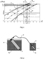
figure 1 est un diagramme pression température représentant les courbes du changement d'état de l'ammoniac et de décomposition du chlorure de baryum utilisées dans un premier mode de mise en oeuvre de l'invention, - la
figure 2 est une représentation schématique d'une installation de remplissage pouvant mettre en oeuvre le procédé de remplissage de l'invention; - la
figure 3 est un diagramme pression température représentant les courbes du changement d'état de l'ammoniac et de décomposition du chlorure de baryum utilisées dans un second mode de mise en oeuvre de l'invention,
- the
figure 1 is a temperature pressure diagram representing the curves of the change of state of ammonia and decomposition of barium chloride used in a first embodiment of the invention, - the
figure 2 is a schematic representation of a filling installation that can implement the filling method of the invention; - the
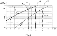
figure 3 is a temperature pressure diagram representing the curves of the change of state of the ammonia and of the decomposition of barium chloride used in a second mode of implementation of the invention,
Dans le premier exemple de mise en oeuvre de l'invention on souhaite remplir de gaz ammoniac un réservoir 1 en vue de le stocker dans celui-ci sous phase solide.In the first example of implementation of the invention it is desired to fill a
Ce réservoir de stockage 1 contient un produit réactif, en l'espèce du chlorure de baryum, en mesure de réagir avec l'ammoniac et de produire un produit de réaction solide suivant la réaction :
BaCl2 + 8(NH3) ↔ BaCl2(NH3)8 + δHR
This
BaCl 2 + 8 (NH 3 ) ↔ BaCl 2 (NH 3 ) 8 + δH R
Le produit réactif est mélangé avec un liant matriciel qui, ainsi que mentionné précédemment, a pour fonction d'une part de permettre une libre circulation du gaz à stocker et un bon contact de celui-ci avec la masse du produit réactif et, d'autre part, d'évacuer vers l'extérieur la chaleur produite par la réaction. On désignera mélange réactif le mélange constitué du produit réactif et du liant matriciel.The reactive product is mixed with a matrix binder which, as mentioned above, has the function on the one hand to allow free circulation of the gas to be stored and good contact thereof with the mass of the reactive product and, on the other hand, to evacuate to the outside the heat produced by the reaction. The reactive mixture of the reactive product and the matrix binder will be referred to as the reactive mixture.
Les essais menés par la déposante on conduit à constater que pour emmagasiner une quantité de gaz qui soit optimale par rapport au volume de stockage, le taux de produit réactif dans le mélange réactif doit être très supérieur à celui utilisé dans les dispositifs de production de froid exploitant une réaction thermochimique de même type.The tests carried out by the applicant led to the conclusion that in order to store a quantity of gas that is optimal with respect to the storage volume, the rate of reactive product in the reaction mixture must be much higher than that used in the cold production devices. exploiting a thermochemical reaction of the same type.
Ainsi, dans ces derniers, le taux T de produit réactif est de l'ordre de 75 à 78% c'est-à-dire que, en masse, le mélange réactif contient 75 à 78% de produit réactif et 25 à 22% de graphite naturel expansé.Thus, in the latter, the rate T of reactive product is of the order of 75 to 78%, that is to say that, by mass, the reaction mixture contains 75 to 78% of reactive product and 25 to 22% expanded natural graphite.
Suivant l'invention on utilise un mélange réactif dans lequel le taux en masse de produit réactif est compris entre 85 et 96% et préférentiellement de l'ordre de 94%. La masse volumique apparente du mélange réactif composé du graphite naturel expansé et du sel réactif sera comprise entre 40 et 120 kg/m3 et préférentiellement de l'ordre de 50 kg/m3. Dans de telles conditions on sait que l'on est en mesure de stocker une quantité de 500g d'ammoniac dans un volume de un litre de mélange réactif.According to the invention, a reactive mixture is used in which the mass ratio of reactive product is between 85 and 96% and preferably of the order of 94%. The apparent density of the reactive mixture composed of expanded natural graphite and of the reactive salt will be between 40 and 120 kg / m 3 and preferably of the order of 50 kg / m 3 . Under such conditions, it is known that 500 g of ammonia can be stored in a volume of one liter of reaction mixture.
Le procédé de remplissage suivant l'invention permet de contrôler la vitesse de remplissage afin notamment de remplir le plus rapidement possible le mélange réactif avec le gaz à stocker sans qu'à aucun moment ce dernier ne passe en phase liquide sous peine de dissoudre le produit réactif et donc de détériorer ce dernier de façon irréversible.The filling method according to the invention makes it possible to control the filling speed in order, in particular, to fill the reactive mixture with the gas to be stored as quickly as possible without at any moment the latter going into the liquid phase, otherwise the product will dissolve. reactive and therefore damage the latter irreversibly.
On a représenté sur la
Dans ce mode de mise en oeuvre de l'invention on choisit une température de remplissage Tr égale par exemple à 22°C et l'on prend en considération le segment AB compris entre le point A représentant la pression de vapeur saturante du gaz à cette température et le point B qui représente la température de décomposition du produit réactif, à savoir le chlorure de baryum, à cette même température. On choisit sur ce segment AB un point C dit point de remplissage. En fonction du choix de ce dernier on sera à même de contrôler le remplissage de façon optimale en fonction des nécessités imposées par l'application choisie.In this embodiment of the invention, a filling temperature T r equal to, for example, 22 ° C. is chosen, and the segment AB between point A representing the saturated vapor pressure of the gas to be taken into consideration is taken into consideration. this temperature and the point B which represents the decomposition temperature of the reactive product, namely barium chloride, at this same temperature. On this segment AB is chosen a point C called the filling point. Depending on the choice of the latter we will be able to control the filling optimally according to the requirements imposed by the chosen application.
Ainsi, plus le point de remplissage C est proche de la courbe a plus le remplissage du réservoir de stockage est rapide mais plus le risque d'admettre dans celui-ci des gouttes de liquide est élevé.Thus, the closer the filling point C is to the curve , the faster the filling of the storage tank, but the greater the risk of admitting drops of liquid into it.
Ainsi, si pour une application donnée, le temps de remplissage du réservoir de stockage 1 n'est pas primordial, mais par contre il est essentiel qu'aucune goutte de gaz liquide ne puisse pénétrer dans celui-ci on choisira un point de remplissage C situé par exemple en position médiane entre les points A et B, ainsi que représenté sur la
Dans ces conditions on constate sur cette dernière que pour la température de remplissage Tr de 22°C et un point de fonctionnement C médian entre A et B, la pression est de 6.105 Pa, ce qui représente la pression de remplissage Pr. Pour l'ammoniac, à cette pression Pr, la température de vaporisation est de 10°C.Under these conditions it is found on the latter that for the filling temperature T r of 22 ° C and a median operating point C between A and B , the pressure is 6.10 5 Pa, which represents the filling pressure P r . For ammonia, at this pressure P r , the vaporization temperature is 10 ° C.
Dans ces conditions, suivant la présente invention, pour remplir d'ammoniac le réservoir de stockage 1, sans qu'à aucun moment au cours de cette opération de remplissage du gaz liquide ne pénètre dans celui-ci, on le porte et on le maintient à une température de remplissage Tr de 22°C et on porte et on maintient le récipient 2 contenant l'ammoniac à une température Tg de 10°C égale à sa température de vaporisation à la pression de remplissage Pr.Under these conditions, according to the present invention, to fill the
Pour ce faire, ainsi que représenté sur la
Suivant l'invention le maintien en température du réservoir de stockage 1 et du récipient 2 contenant l'ammoniac peut être effectué avec d'autres moyens que des bains thermostatés et par exemple à l'aide de colliers chauffants ou refroidissants.According to the invention the temperature maintenance of the
On peut définir des courbes respectives pour lesquelles tous les points de remplissage C se trouvent dans une position déterminée sur le segment AB et notamment au milieu de celui-ci.We can define respective curves for which all the filling points C are in a specific position on the segment AB and in particular in the middle thereof.
On a représenté sur la
On a porté sur celle-ci un second point de remplissage C' qui correspond à une autre température de remplissage T'r, 25°C et l'on obtient alors une pression de remplissage P'r de 8.105 Pa pour laquelle la température de vaporisation de l'ammoniac T'g est égale à 15°C. Dans ces conditions on maintiendra, pendant le remplissage, le réservoir de stockage 1 à une température T'r de 25°C et le récipient 2 contenant l'ammoniac à une température T'g de 15°C.A second filling point C ', which corresponds to another filling temperature T'r, 25 ° C has been brought to the latter, and a filling pressure P'r of 8.10 5 Pa is obtained for which the temperature ammonia vaporization T'g is equal to 15 ° C. Under these conditions, during storage, the
Ainsi que mentionné précédemment, et en fonction des applications, le point de remplissage C peut être déplacé sur le segment AB et les limites de ce positionnement peuvent être telles que AC et BC soient ≥ AB/10.As mentioned above, and depending on the applications, the filling point C can be moved on the segment AB and the limits of this positioning can be such that AC and BC are ≥ AB / 10.
Dans ces conditions, Pr étant la pression de remplissage du réservoir de stockage 1, Pe étant la pression d'équilibre du produit réactif à la température de remplissage Tr, et Ps étant la pression de vapeur saturante du gaz à la température de remplissage Tr :![]()
![]()
Dans un autre mode de mise en oeuvre de la présente invention et ainsi que représenté sur la
Dans ces conditions, Tr étant la température de remplissage du réservoir de stockage 1, Tg étant la température de vaporisation du gaz à la pression de remplissage Pr, Te étant la température d'équilibre du produit réactif à la pression de remplissage Pr, et Tg étant la température de vaporisation du gaz à cette même pression:![]()
![]()
Ainsi, si pour une application donnée, le temps de remplissage du réservoir de stockage 1 n'est pas primordial, mais par contre il est essentiel qu'aucune goutte de gaz liquide ne puisse pénétrer dans le celui-ci on choisira un point de remplissage C situé par exemple en position médiane entre les points A et B. Dans ces conditions pour une pression de remplissage Pr de 5.105 Pa la température de remplissage Tr à laquelle on maintiendra le réservoir de stockage 1 pendant l'opération de remplissage sera de 20°C et la température Tg à laquelle on maintiendra le récipient 2 contenant le gaz sera dès lors de 4°C.Thus, if for a given application, the filling time of the
Par contre si pour une autre application le temps de remplissage est primordial on choisira alors un point de fonctionnement C' plus proche du point A avec le risque d'admettre quelques gouttes de gaz liquide dans le réservoir de stockage 1 au détriment bien entendu de la longévité du produit réactif. Dans ces conditions la température T'r à laquelle on maintiendra le réservoir de stockage 1 pendant le remplissage sera alors de 10°C.On the other hand, if for another application the filling time is essential then one will choose an operating point C ' closer to the point A with the risk of admitting a few drops of liquid gas in the
Claims (11)
- A process for filling a tank (1) with a gas in a gaseous phase for storage therein in solid phase, the storage tank (1) containing for this purpose a reactive product, the reactive product and the gas being such that, when they are brought into contact with each other, they are subject to a thermochemical reaction having the effect of the absorption of the gas by the reactive product and the production of a solid reaction product and, conversely, they are the subject of a desorption reaction of the gas absorbed by the reactive product under the effect of heating applied to said reactive product, when said reactive product has absorbed gas, characterized in that said gas is introduced into the storage tank (1) ;- either at a filling pressure (Pr) which is equal to the equilibrium pressure of the reactive product at the filling temperature plus α times the difference between the saturation vapor pressure (Ps) of the gas at the filling temperature (Tr) and the equilibrium pressure of the reactive product at said filling temperature; the value of α being comprises between 0.1 and 0.9 and preferably being equal to 0.5 ;- or at a filling temperature (Tr) which is equal to the vaporization temperature of the gas at the filling pressure (Pr) plus β times the difference between the equilibrium temperature (Te) of said product reactive at the filling pressure (Pr) and the vaporization temperature of said gas at said filling pressure; the value of β being between 0.1 and 0.9 and preferably being equal to 0.5.
- The filling process according to claim 1, characterized in that said filling pressure (Pr) is adjusted by acting on the temperature (Tr) of the storage tank (1) and/or on the temperature of a container (2) containing said gas.
- The filling process according to claim 2, characterized in that during filling:- said storage tank (1) and said container (2) containing said gas are kept at a constant temperature,- for a given filling temperature (Tr), the temperature (Tg) for keeping the container (2) containing said gas is equal to the vaporization temperature of said gas at said filling pressure (Pr).
- The filling process according to claim 3, characterized in that said keeping temperature is obtained by immersion of said storage tank (1) and/or said container (2) containing said gas in a thermostatic bath.
- The filling process according to one of the above-mentioned claims, characterized in that said reactive product is mixed with a "matrix binder" to form a reactive mixture.
- The filling process according to claim 5, characterized in that said matrix binder consists of expanded natural graphite.
- The filling process according to claim 6, characterized in that said reactive mixture is composed of said reactive product and expanded natural graphite, in that the bulk density of said expanded natural graphite is between 40 kg/m3 and 120 kg/m3 and preferably of about 50 kg/m3.
- The filling method according to one of the above-mentioned claims characterized in that said gas is ammonia.
- The filling process according to one of claims 5 to 8, characterized in that said reactive mixture comprises by weight between 50% and 98% of said reactive product and preferably about 94% by weight of said reactive product.
- The filling process according to one of the above-mentioned claims, characterized in that said reactive product consists in particular of alkaline salts, alkaline earth salts or metal salts.
- The filling process according to claim 10, characterized in that said reactive product consists of alkaline salts, alkaline earth salts or metal salts and in particular of calcium chloride, barium chloride or manganese chloride.
Applications Claiming Priority (2)
| Application Number | Priority Date | Filing Date | Title |
|---|---|---|---|
| FR1102515A FR2979002B1 (en) | 2011-08-12 | 2011-08-12 | METHOD FOR FILLING A GAS STORAGE TANK |
| PCT/FR2012/051841 WO2013024224A1 (en) | 2011-08-12 | 2012-08-02 | Method for filling a gas storage tank |
Publications (2)
| Publication Number | Publication Date |
|---|---|
| EP2742275A1 EP2742275A1 (en) | 2014-06-18 |
| EP2742275B1 true EP2742275B1 (en) | 2018-05-09 |
Family
ID=46750362
Family Applications (1)
| Application Number | Title | Priority Date | Filing Date |
|---|---|---|---|
| EP12751096.4A Active EP2742275B1 (en) | 2011-08-12 | 2012-08-02 | Method of filling a gas storage tank |
Country Status (8)
| Country | Link |
|---|---|
| US (1) | US9625096B2 (en) |
| EP (1) | EP2742275B1 (en) |
| JP (1) | JP2014525548A (en) |
| CN (1) | CN103842709B (en) |
| CA (1) | CA2844912A1 (en) |
| ES (1) | ES2672264T3 (en) |
| FR (1) | FR2979002B1 (en) |
| WO (1) | WO2013024224A1 (en) |
Families Citing this family (1)
| Publication number | Priority date | Publication date | Assignee | Title |
|---|---|---|---|---|
| CN108332814B (en) * | 2018-01-11 | 2020-04-07 | 浙江约顿智造科技有限公司 | Method for calculating weight of storage object in air film |
Family Cites Families (16)
| Publication number | Priority date | Publication date | Assignee | Title |
|---|---|---|---|---|
| FR1502818A (en) * | 1966-09-15 | 1967-11-24 | Exxon Research Engineering Co | Advanced process for the synthesis of ammonia |
| US5441716A (en) * | 1989-03-08 | 1995-08-15 | Rocky Research | Method and apparatus for achieving high reaction rates |
| US5458784A (en) * | 1990-10-23 | 1995-10-17 | Catalytic Materials Limited | Removal of contaminants from aqueous and gaseous streams using graphic filaments |
| JP4490557B2 (en) * | 2000-06-09 | 2010-06-30 | 本田技研工業株式会社 | Rapid hydrogen filling method |
| FR2847586B1 (en) * | 2002-11-27 | 2005-01-14 | Centre Nat Rech Scient | COMPOSITE MATERIAL, ITS USE FOR THE MANAGEMENT OF THERMAL EFFECTS IN A PHYSICO-CHEMICAL PROCESS |
| US7297181B2 (en) * | 2004-07-07 | 2007-11-20 | Air Liquide America L.P. | Purification and transfilling of ammonia |
| DE102006052109A1 (en) * | 2006-11-06 | 2008-05-08 | Robert Bosch Gmbh | Fluid storage with thermal management |
| WO2009057127A1 (en) * | 2007-11-01 | 2009-05-07 | Patel Phirose | A system for effective storing and fuelling of hydrogen |
| JP5211357B2 (en) * | 2008-03-10 | 2013-06-12 | 国立大学法人広島大学 | Hydrogen storage station, hydrogen supply station and composite cartridge |
| EP2342009B1 (en) * | 2008-09-08 | 2017-03-15 | Amminex Emissions Technology A/S | Additives for highly compacted ammonia storage materials |
| US8680006B2 (en) * | 2008-09-08 | 2014-03-25 | Amminex Emissions Technology A/S | Saturation of ammonia storage materials in containers |
| FR2939784B1 (en) * | 2008-12-16 | 2012-02-03 | Centre Nat Rech Scient | ADIABATIC METAL HYDRIDE RESERVOIR |
| EP2236784B1 (en) * | 2009-03-18 | 2012-06-06 | Amminex A/S | Improved method for storing and delivering ammonia from solid storage materials using a vacuum pump |
| EP2388058A1 (en) * | 2010-05-19 | 2011-11-23 | Amminex A/S | Method and device for re-saturation of ammonia storage material in containers |
| US8473226B2 (en) * | 2010-09-17 | 2013-06-25 | Amminex A/S | Method of determining the filling level of a solid ammonia storage medium in an ammonia storage container |
| FR2979001B1 (en) * | 2011-08-12 | 2014-08-29 | Coldway | METHOD FOR SOLID STORAGE STORAGE OF A GAS |
-
2011
- 2011-08-12 FR FR1102515A patent/FR2979002B1/en not_active Expired - Fee Related
-
2012
- 2012-08-02 ES ES12751096.4T patent/ES2672264T3/en active Active
- 2012-08-02 WO PCT/FR2012/051841 patent/WO2013024224A1/en active Application Filing
- 2012-08-02 EP EP12751096.4A patent/EP2742275B1/en active Active
- 2012-08-02 JP JP2014524431A patent/JP2014525548A/en active Pending
- 2012-08-02 US US14/233,428 patent/US9625096B2/en not_active Expired - Fee Related
- 2012-08-02 CA CA2844912A patent/CA2844912A1/en not_active Abandoned
- 2012-08-02 CN CN201280047063.1A patent/CN103842709B/en not_active Expired - Fee Related
Non-Patent Citations (1)
| Title |
|---|
| None * |
Also Published As
| Publication number | Publication date |
|---|---|
| CN103842709A (en) | 2014-06-04 |
| US20140202587A1 (en) | 2014-07-24 |
| ES2672264T3 (en) | 2018-06-13 |
| JP2014525548A (en) | 2014-09-29 |
| CN103842709B (en) | 2016-04-20 |
| FR2979002A1 (en) | 2013-02-15 |
| WO2013024224A1 (en) | 2013-02-21 |
| US9625096B2 (en) | 2017-04-18 |
| FR2979002B1 (en) | 2014-11-07 |
| CA2844912A1 (en) | 2013-02-21 |
| EP2742275A1 (en) | 2014-06-18 |
Similar Documents
| Publication | Publication Date | Title |
|---|---|---|
| EP2742274A1 (en) | Method for storing a gas by chemisorption on a porous material comprising expanded graphite | |
| EP0316391B1 (en) | Process for producing cold by solid-gas reaction | |
| CA1135518A (en) | Improved cold and/or heat production process with an absorption cycle | |
| CA1236312A (en) | Tri-phased heat pump | |
| Susilo et al. | Methane conversion rate into structure H hydrate crystals from ice | |
| Babakhani et al. | Effect of maize starch on methane hydrate formation/dissociation rates and stability | |
| EP2742275B1 (en) | Method of filling a gas storage tank | |
| FR3022617A1 (en) | METHOD FOR PRODUCING A DEVICE FOR STORING THERMAL ENERGY BY SOLID PHASE / SOLID PHASE CHANGE MATERIAL | |
| WO2013164539A1 (en) | Device and method for the continuous thermochemical production of cold | |
| Petuya et al. | Phase Behavior of Clathrate Hydrates in the Ternary H2O–NH3–Cyclopentane System | |
| EP1529185A2 (en) | Installation and method for producing cold by a reversible sorption system | |
| EP0810410A1 (en) | Method of controlling a thermochemical reaction or a solid-gas adsorption | |
| WO2021190819A1 (en) | Method and device for releasing a ballast in an underwater environment | |
| EP1523643B1 (en) | Method for producing cold and installation therefor | |
| Becker-Glad et al. | Acid acceleration of hydrogen generation using seawater as a reactant | |
| WO2016051076A1 (en) | Method for getting the inside of a thermally insulated space up to temperature and maintaining it at temperature without the provision of continuous energy, and associated device | |
| EP1608920B1 (en) | Method and device for rapid and high- power cold production | |
| Zent et al. | In-Situ Segregation of Ground Ice on Mars | |
| Ambuehl | The effect of CO₂ infused ice on the formation and dissociation of CO₂ hydrate | |
| Boinon et al. | Les systemes binaires fluorure de lithium-fluorure d'hydrogene et fluorure de sodium-fluorure d'hydrogene | |
| Vu et al. | Kinetics of Ethane Clathrate Hydrate Formation under Titan-Like Conditions | |
| JPH01197301A (en) | Hydrogen storage vessel | |
| EP1556163A2 (en) | Method for using a thermochemical transformer, and device comprising a chemical reactor and a thermochemical transformer | |
| FR3071046A1 (en) | REFRIGERATION FACILITY OF ISOTHERMAL BOX UP TO TARGET TEMPERATURE - ASSOCIATED METHOD | |
| Chen et al. | Kinetics Characteristics of Nitrogen Hydrates Respond to Differential Scanning Calorimetry |
Legal Events
| Date | Code | Title | Description |
|---|---|---|---|
| PUAI | Public reference made under article 153(3) epc to a published international application that has entered the european phase |
Free format text: ORIGINAL CODE: 0009012 |
|
| 17P | Request for examination filed |
Effective date: 20140212 |
|
| AK | Designated contracting states |
Kind code of ref document: A1 Designated state(s): AL AT BE BG CH CY CZ DE DK EE ES FI FR GB GR HR HU IE IS IT LI LT LU LV MC MK MT NL NO PL PT RO RS SE SI SK SM TR |
|
| AX | Request for extension of the european patent |
Extension state: BA ME |
|
| 17Q | First examination report despatched |
Effective date: 20170127 |
|
| GRAP | Despatch of communication of intention to grant a patent |
Free format text: ORIGINAL CODE: EPIDOSNIGR1 |
|
| RIC1 | Information provided on ipc code assigned before grant |
Ipc: F17C 11/00 20060101AFI20171122BHEP Ipc: C01C 1/00 20060101ALI20171122BHEP Ipc: C01B 3/00 20060101ALI20171122BHEP |
|
| INTG | Intention to grant announced |
Effective date: 20171208 |
|
| GRAS | Grant fee paid |
Free format text: ORIGINAL CODE: EPIDOSNIGR3 |
|
| GRAA | (expected) grant |
Free format text: ORIGINAL CODE: 0009210 |
|
| AK | Designated contracting states |
Kind code of ref document: B1 Designated state(s): AL AT BE BG CH CY CZ DE DK EE ES FI FR GB GR HR HU IE IS IT LI LT LU LV MC MK MT NL NO PL PT RO RS SE SI SK SM TR |
|
| AX | Request for extension of the european patent |
Extension state: BA ME |
|
| REG | Reference to a national code |
Ref country code: GB Ref legal event code: FG4D Free format text: NOT ENGLISH |
|
| REG | Reference to a national code |
Ref country code: CH Ref legal event code: EP Ref country code: AT Ref legal event code: REF Ref document number: 997902 Country of ref document: AT Kind code of ref document: T Effective date: 20180515 |
|
| REG | Reference to a national code |
Ref country code: IE Ref legal event code: FG4D Free format text: LANGUAGE OF EP DOCUMENT: FRENCH |
|
| REG | Reference to a national code |
Ref country code: DE Ref legal event code: R096 Ref document number: 602012046170 Country of ref document: DE |
|
| REG | Reference to a national code |
Ref country code: ES Ref legal event code: FG2A Ref document number: 2672264 Country of ref document: ES Kind code of ref document: T3 Effective date: 20180613 |
|
| REG | Reference to a national code |
Ref country code: SE Ref legal event code: TRGR |
|
| REG | Reference to a national code |
Ref country code: NL Ref legal event code: MP Effective date: 20180509 |
|
| REG | Reference to a national code |
Ref country code: LT Ref legal event code: MG4D |
|
| PG25 | Lapsed in a contracting state [announced via postgrant information from national office to epo] |
Ref country code: LT Free format text: LAPSE BECAUSE OF FAILURE TO SUBMIT A TRANSLATION OF THE DESCRIPTION OR TO PAY THE FEE WITHIN THE PRESCRIBED TIME-LIMIT Effective date: 20180509 Ref country code: NO Free format text: LAPSE BECAUSE OF FAILURE TO SUBMIT A TRANSLATION OF THE DESCRIPTION OR TO PAY THE FEE WITHIN THE PRESCRIBED TIME-LIMIT Effective date: 20180809 Ref country code: BG Free format text: LAPSE BECAUSE OF FAILURE TO SUBMIT A TRANSLATION OF THE DESCRIPTION OR TO PAY THE FEE WITHIN THE PRESCRIBED TIME-LIMIT Effective date: 20180809 Ref country code: FI Free format text: LAPSE BECAUSE OF FAILURE TO SUBMIT A TRANSLATION OF THE DESCRIPTION OR TO PAY THE FEE WITHIN THE PRESCRIBED TIME-LIMIT Effective date: 20180509 |
|
| PG25 | Lapsed in a contracting state [announced via postgrant information from national office to epo] |
Ref country code: GR Free format text: LAPSE BECAUSE OF FAILURE TO SUBMIT A TRANSLATION OF THE DESCRIPTION OR TO PAY THE FEE WITHIN THE PRESCRIBED TIME-LIMIT Effective date: 20180810 Ref country code: RS Free format text: LAPSE BECAUSE OF FAILURE TO SUBMIT A TRANSLATION OF THE DESCRIPTION OR TO PAY THE FEE WITHIN THE PRESCRIBED TIME-LIMIT Effective date: 20180509 Ref country code: LV Free format text: LAPSE BECAUSE OF FAILURE TO SUBMIT A TRANSLATION OF THE DESCRIPTION OR TO PAY THE FEE WITHIN THE PRESCRIBED TIME-LIMIT Effective date: 20180509 Ref country code: NL Free format text: LAPSE BECAUSE OF FAILURE TO SUBMIT A TRANSLATION OF THE DESCRIPTION OR TO PAY THE FEE WITHIN THE PRESCRIBED TIME-LIMIT Effective date: 20180509 Ref country code: HR Free format text: LAPSE BECAUSE OF FAILURE TO SUBMIT A TRANSLATION OF THE DESCRIPTION OR TO PAY THE FEE WITHIN THE PRESCRIBED TIME-LIMIT Effective date: 20180509 |
|
| REG | Reference to a national code |
Ref country code: AT Ref legal event code: MK05 Ref document number: 997902 Country of ref document: AT Kind code of ref document: T Effective date: 20180509 |
|
| PG25 | Lapsed in a contracting state [announced via postgrant information from national office to epo] |
Ref country code: CZ Free format text: LAPSE BECAUSE OF FAILURE TO SUBMIT A TRANSLATION OF THE DESCRIPTION OR TO PAY THE FEE WITHIN THE PRESCRIBED TIME-LIMIT Effective date: 20180509 Ref country code: SK Free format text: LAPSE BECAUSE OF FAILURE TO SUBMIT A TRANSLATION OF THE DESCRIPTION OR TO PAY THE FEE WITHIN THE PRESCRIBED TIME-LIMIT Effective date: 20180509 Ref country code: EE Free format text: LAPSE BECAUSE OF FAILURE TO SUBMIT A TRANSLATION OF THE DESCRIPTION OR TO PAY THE FEE WITHIN THE PRESCRIBED TIME-LIMIT Effective date: 20180509 Ref country code: PL Free format text: LAPSE BECAUSE OF FAILURE TO SUBMIT A TRANSLATION OF THE DESCRIPTION OR TO PAY THE FEE WITHIN THE PRESCRIBED TIME-LIMIT Effective date: 20180509 Ref country code: DK Free format text: LAPSE BECAUSE OF FAILURE TO SUBMIT A TRANSLATION OF THE DESCRIPTION OR TO PAY THE FEE WITHIN THE PRESCRIBED TIME-LIMIT Effective date: 20180509 Ref country code: RO Free format text: LAPSE BECAUSE OF FAILURE TO SUBMIT A TRANSLATION OF THE DESCRIPTION OR TO PAY THE FEE WITHIN THE PRESCRIBED TIME-LIMIT Effective date: 20180509 Ref country code: AT Free format text: LAPSE BECAUSE OF FAILURE TO SUBMIT A TRANSLATION OF THE DESCRIPTION OR TO PAY THE FEE WITHIN THE PRESCRIBED TIME-LIMIT Effective date: 20180509 |
|
| REG | Reference to a national code |
Ref country code: DE Ref legal event code: R097 Ref document number: 602012046170 Country of ref document: DE |
|
| PG25 | Lapsed in a contracting state [announced via postgrant information from national office to epo] |
Ref country code: SM Free format text: LAPSE BECAUSE OF FAILURE TO SUBMIT A TRANSLATION OF THE DESCRIPTION OR TO PAY THE FEE WITHIN THE PRESCRIBED TIME-LIMIT Effective date: 20180509 |
|
| REG | Reference to a national code |
Ref country code: DE Ref legal event code: R119 Ref document number: 602012046170 Country of ref document: DE |
|
| PLBE | No opposition filed within time limit |
Free format text: ORIGINAL CODE: 0009261 |
|
| STAA | Information on the status of an ep patent application or granted ep patent |
Free format text: STATUS: NO OPPOSITION FILED WITHIN TIME LIMIT |
|
| PG25 | Lapsed in a contracting state [announced via postgrant information from national office to epo] |
Ref country code: MC Free format text: LAPSE BECAUSE OF FAILURE TO SUBMIT A TRANSLATION OF THE DESCRIPTION OR TO PAY THE FEE WITHIN THE PRESCRIBED TIME-LIMIT Effective date: 20180509 |
|
| REG | Reference to a national code |
Ref country code: CH Ref legal event code: PL |
|
| REG | Reference to a national code |
Ref country code: SE Ref legal event code: EUG |
|
| 26N | No opposition filed |
Effective date: 20190212 |
|
| GBPC | Gb: european patent ceased through non-payment of renewal fee |
Effective date: 20180809 |
|
| PG25 | Lapsed in a contracting state [announced via postgrant information from national office to epo] |
Ref country code: LU Free format text: LAPSE BECAUSE OF NON-PAYMENT OF DUE FEES Effective date: 20180802 Ref country code: CH Free format text: LAPSE BECAUSE OF NON-PAYMENT OF DUE FEES Effective date: 20180831 Ref country code: LI Free format text: LAPSE BECAUSE OF NON-PAYMENT OF DUE FEES Effective date: 20180831 |
|
| REG | Reference to a national code |
Ref country code: BE Ref legal event code: MM Effective date: 20180831 |
|
| REG | Reference to a national code |
Ref country code: IE Ref legal event code: MM4A |
|
| PG25 | Lapsed in a contracting state [announced via postgrant information from national office to epo] |
Ref country code: SE Free format text: LAPSE BECAUSE OF NON-PAYMENT OF DUE FEES Effective date: 20180803 Ref country code: SI Free format text: LAPSE BECAUSE OF FAILURE TO SUBMIT A TRANSLATION OF THE DESCRIPTION OR TO PAY THE FEE WITHIN THE PRESCRIBED TIME-LIMIT Effective date: 20180509 |
|
| PG25 | Lapsed in a contracting state [announced via postgrant information from national office to epo] |
Ref country code: DE Free format text: LAPSE BECAUSE OF NON-PAYMENT OF DUE FEES Effective date: 20190301 Ref country code: IT Free format text: LAPSE BECAUSE OF NON-PAYMENT OF DUE FEES Effective date: 20180802 Ref country code: IE Free format text: LAPSE BECAUSE OF NON-PAYMENT OF DUE FEES Effective date: 20180802 |
|
| PG25 | Lapsed in a contracting state [announced via postgrant information from national office to epo] |
Ref country code: BE Free format text: LAPSE BECAUSE OF NON-PAYMENT OF DUE FEES Effective date: 20180831 Ref country code: FR Free format text: LAPSE BECAUSE OF NON-PAYMENT OF DUE FEES Effective date: 20180831 |
|
| REG | Reference to a national code |
Ref country code: ES Ref legal event code: FD2A Effective date: 20190918 |
|
| PG25 | Lapsed in a contracting state [announced via postgrant information from national office to epo] |
Ref country code: ES Free format text: LAPSE BECAUSE OF NON-PAYMENT OF DUE FEES Effective date: 20180803 Ref country code: GB Free format text: LAPSE BECAUSE OF NON-PAYMENT OF DUE FEES Effective date: 20180809 |
|
| PG25 | Lapsed in a contracting state [announced via postgrant information from national office to epo] |
Ref country code: AL Free format text: LAPSE BECAUSE OF FAILURE TO SUBMIT A TRANSLATION OF THE DESCRIPTION OR TO PAY THE FEE WITHIN THE PRESCRIBED TIME-LIMIT Effective date: 20180509 |
|
| PG25 | Lapsed in a contracting state [announced via postgrant information from national office to epo] |
Ref country code: MT Free format text: LAPSE BECAUSE OF FAILURE TO SUBMIT A TRANSLATION OF THE DESCRIPTION OR TO PAY THE FEE WITHIN THE PRESCRIBED TIME-LIMIT Effective date: 20180509 |
|
| PG25 | Lapsed in a contracting state [announced via postgrant information from national office to epo] |
Ref country code: TR Free format text: LAPSE BECAUSE OF FAILURE TO SUBMIT A TRANSLATION OF THE DESCRIPTION OR TO PAY THE FEE WITHIN THE PRESCRIBED TIME-LIMIT Effective date: 20180509 |
|
| PG25 | Lapsed in a contracting state [announced via postgrant information from national office to epo] |
Ref country code: HU Free format text: LAPSE BECAUSE OF FAILURE TO SUBMIT A TRANSLATION OF THE DESCRIPTION OR TO PAY THE FEE WITHIN THE PRESCRIBED TIME-LIMIT; INVALID AB INITIO Effective date: 20120802 Ref country code: PT Free format text: LAPSE BECAUSE OF FAILURE TO SUBMIT A TRANSLATION OF THE DESCRIPTION OR TO PAY THE FEE WITHIN THE PRESCRIBED TIME-LIMIT Effective date: 20180509 |
|
| PG25 | Lapsed in a contracting state [announced via postgrant information from national office to epo] |
Ref country code: CY Free format text: LAPSE BECAUSE OF FAILURE TO SUBMIT A TRANSLATION OF THE DESCRIPTION OR TO PAY THE FEE WITHIN THE PRESCRIBED TIME-LIMIT Effective date: 20180509 Ref country code: MK Free format text: LAPSE BECAUSE OF NON-PAYMENT OF DUE FEES Effective date: 20180509 |
|
| PG25 | Lapsed in a contracting state [announced via postgrant information from national office to epo] |
Ref country code: IS Free format text: LAPSE BECAUSE OF FAILURE TO SUBMIT A TRANSLATION OF THE DESCRIPTION OR TO PAY THE FEE WITHIN THE PRESCRIBED TIME-LIMIT Effective date: 20180909 |