EP1523643B1 - Method for producing cold and installation therefor - Google Patents
Method for producing cold and installation therefor Download PDFInfo
- Publication number
- EP1523643B1 EP1523643B1 EP03771135A EP03771135A EP1523643B1 EP 1523643 B1 EP1523643 B1 EP 1523643B1 EP 03771135 A EP03771135 A EP 03771135A EP 03771135 A EP03771135 A EP 03771135A EP 1523643 B1 EP1523643 B1 EP 1523643B1
- Authority
- EP
- European Patent Office
- Prior art keywords
- reactor
- gas
- temperature
- installation
- chambers
- Prior art date
- Legal status (The legal status is an assumption and is not a legal conclusion. Google has not performed a legal analysis and makes no representation as to the accuracy of the status listed.)
- Expired - Lifetime
Links
- 238000009434 installation Methods 0.000 title claims abstract description 35
- 238000004519 manufacturing process Methods 0.000 title description 30
- 238000001179 sorption measurement Methods 0.000 claims abstract description 40
- 230000002441 reversible effect Effects 0.000 claims abstract description 29
- 238000004891 communication Methods 0.000 claims abstract description 24
- 238000000034 method Methods 0.000 claims abstract description 24
- 238000010438 heat treatment Methods 0.000 claims abstract description 12
- 238000005057 refrigeration Methods 0.000 claims abstract description 7
- 238000000605 extraction Methods 0.000 claims abstract description 3
- 239000012071 phase Substances 0.000 claims description 68
- 230000015572 biosynthetic process Effects 0.000 claims description 24
- 238000003786 synthesis reaction Methods 0.000 claims description 24
- 239000007788 liquid Substances 0.000 claims description 23
- 239000002594 sorbent Substances 0.000 claims description 20
- 238000000354 decomposition reaction Methods 0.000 claims description 15
- XLYOFNOQVPJJNP-UHFFFAOYSA-N water Substances O XLYOFNOQVPJJNP-UHFFFAOYSA-N 0.000 claims description 15
- 239000007787 solid Substances 0.000 claims description 13
- 239000012782 phase change material Substances 0.000 claims description 12
- 238000006243 chemical reaction Methods 0.000 claims description 9
- 239000000463 material Substances 0.000 claims description 8
- 230000009102 absorption Effects 0.000 claims description 5
- 238000010521 absorption reaction Methods 0.000 claims description 5
- 238000009835 boiling Methods 0.000 claims description 3
- 239000007791 liquid phase Substances 0.000 claims description 3
- 239000007790 solid phase Substances 0.000 claims description 3
- 150000001875 compounds Chemical class 0.000 claims description 2
- 230000001172 regenerating effect Effects 0.000 claims 1
- 239000007789 gas Substances 0.000 description 47
- 238000009833 condensation Methods 0.000 description 20
- 230000005494 condensation Effects 0.000 description 20
- 230000008929 regeneration Effects 0.000 description 16
- 238000011069 regeneration method Methods 0.000 description 16
- 238000001816 cooling Methods 0.000 description 10
- 238000001704 evaporation Methods 0.000 description 8
- 230000008020 evaporation Effects 0.000 description 8
- 238000010586 diagram Methods 0.000 description 7
- QGZKDVFQNNGYKY-UHFFFAOYSA-N Ammonia Chemical compound N QGZKDVFQNNGYKY-UHFFFAOYSA-N 0.000 description 4
- 230000008018 melting Effects 0.000 description 4
- 238000002844 melting Methods 0.000 description 4
- 230000007423 decrease Effects 0.000 description 3
- 230000008014 freezing Effects 0.000 description 3
- 238000007710 freezing Methods 0.000 description 3
- 150000003839 salts Chemical class 0.000 description 3
- OKTJSMMVPCPJKN-UHFFFAOYSA-N Carbon Chemical compound [C] OKTJSMMVPCPJKN-UHFFFAOYSA-N 0.000 description 2
- CURLTUGMZLYLDI-UHFFFAOYSA-N Carbon dioxide Chemical compound O=C=O CURLTUGMZLYLDI-UHFFFAOYSA-N 0.000 description 2
- 229910021529 ammonia Inorganic materials 0.000 description 2
- 238000003795 desorption Methods 0.000 description 2
- 230000005496 eutectics Effects 0.000 description 2
- 229910052739 hydrogen Inorganic materials 0.000 description 2
- 239000001257 hydrogen Substances 0.000 description 2
- 125000004435 hydrogen atom Chemical class [H]* 0.000 description 2
- AMXOYNBUYSYVKV-UHFFFAOYSA-M lithium bromide Chemical compound [Li+].[Br-] AMXOYNBUYSYVKV-UHFFFAOYSA-M 0.000 description 2
- VNWKTOKETHGBQD-UHFFFAOYSA-N methane Chemical compound C VNWKTOKETHGBQD-UHFFFAOYSA-N 0.000 description 2
- 230000008023 solidification Effects 0.000 description 2
- 238000007711 solidification Methods 0.000 description 2
- 241001272720 Medialuna californiensis Species 0.000 description 1
- UCKMPCXJQFINFW-UHFFFAOYSA-N Sulphide Chemical compound [S-2] UCKMPCXJQFINFW-UHFFFAOYSA-N 0.000 description 1
- 229910021536 Zeolite Inorganic materials 0.000 description 1
- 239000003570 air Substances 0.000 description 1
- XAGFODPZIPBFFR-UHFFFAOYSA-N aluminium Chemical compound [Al] XAGFODPZIPBFFR-UHFFFAOYSA-N 0.000 description 1
- 229910052782 aluminium Inorganic materials 0.000 description 1
- 239000012080 ambient air Substances 0.000 description 1
- 150000003842 bromide salts Chemical class 0.000 description 1
- 125000004432 carbon atom Chemical group C* 0.000 description 1
- 229910002092 carbon dioxide Inorganic materials 0.000 description 1
- 239000001569 carbon dioxide Substances 0.000 description 1
- 150000004649 carbonic acid derivatives Chemical class 0.000 description 1
- 150000003841 chloride salts Chemical class 0.000 description 1
- 239000012809 cooling fluid Substances 0.000 description 1
- 238000009792 diffusion process Methods 0.000 description 1
- HNPSIPDUKPIQMN-UHFFFAOYSA-N dioxosilane;oxo(oxoalumanyloxy)alumane Chemical compound O=[Si]=O.O=[Al]O[Al]=O HNPSIPDUKPIQMN-UHFFFAOYSA-N 0.000 description 1
- 230000000694 effects Effects 0.000 description 1
- 238000005265 energy consumption Methods 0.000 description 1
- 239000000374 eutectic mixture Substances 0.000 description 1
- 230000004927 fusion Effects 0.000 description 1
- 150000004677 hydrates Chemical class 0.000 description 1
- 150000004678 hydrides Chemical class 0.000 description 1
- 239000005457 ice water Substances 0.000 description 1
- 230000001939 inductive effect Effects 0.000 description 1
- 150000004694 iodide salts Chemical class 0.000 description 1
- 239000003345 natural gas Substances 0.000 description 1
- 238000005192 partition Methods 0.000 description 1
- 238000000926 separation method Methods 0.000 description 1
- 238000003860 storage Methods 0.000 description 1
- 150000003467 sulfuric acid derivatives Chemical class 0.000 description 1
- 239000010457 zeolite Substances 0.000 description 1
Images


Classifications
-
- F—MECHANICAL ENGINEERING; LIGHTING; HEATING; WEAPONS; BLASTING
- F25—REFRIGERATION OR COOLING; COMBINED HEATING AND REFRIGERATION SYSTEMS; HEAT PUMP SYSTEMS; MANUFACTURE OR STORAGE OF ICE; LIQUEFACTION SOLIDIFICATION OF GASES
- F25B—REFRIGERATION MACHINES, PLANTS OR SYSTEMS; COMBINED HEATING AND REFRIGERATION SYSTEMS; HEAT PUMP SYSTEMS
- F25B17/00—Sorption machines, plants or systems, operating intermittently, e.g. absorption or adsorption type
- F25B17/08—Sorption machines, plants or systems, operating intermittently, e.g. absorption or adsorption type the absorbent or adsorbent being a solid, e.g. salt
- F25B17/083—Sorption machines, plants or systems, operating intermittently, e.g. absorption or adsorption type the absorbent or adsorbent being a solid, e.g. salt with two or more boiler-sorbers operating alternately
-
- F—MECHANICAL ENGINEERING; LIGHTING; HEATING; WEAPONS; BLASTING
- F25—REFRIGERATION OR COOLING; COMBINED HEATING AND REFRIGERATION SYSTEMS; HEAT PUMP SYSTEMS; MANUFACTURE OR STORAGE OF ICE; LIQUEFACTION SOLIDIFICATION OF GASES
- F25B—REFRIGERATION MACHINES, PLANTS OR SYSTEMS; COMBINED HEATING AND REFRIGERATION SYSTEMS; HEAT PUMP SYSTEMS
- F25B17/00—Sorption machines, plants or systems, operating intermittently, e.g. absorption or adsorption type
- F25B17/02—Sorption machines, plants or systems, operating intermittently, e.g. absorption or adsorption type the absorbent or adsorbent being a liquid, e.g. brine
- F25B17/04—Sorption machines, plants or systems, operating intermittently, e.g. absorption or adsorption type the absorbent or adsorbent being a liquid, e.g. brine with two or more boilers operating alternately
-
- F—MECHANICAL ENGINEERING; LIGHTING; HEATING; WEAPONS; BLASTING
- F25—REFRIGERATION OR COOLING; COMBINED HEATING AND REFRIGERATION SYSTEMS; HEAT PUMP SYSTEMS; MANUFACTURE OR STORAGE OF ICE; LIQUEFACTION SOLIDIFICATION OF GASES
- F25B—REFRIGERATION MACHINES, PLANTS OR SYSTEMS; COMBINED HEATING AND REFRIGERATION SYSTEMS; HEAT PUMP SYSTEMS
- F25B39/00—Evaporators; Condensers
- F25B39/02—Evaporators
- F25B39/026—Evaporators specially adapted for sorption type systems
-
- F—MECHANICAL ENGINEERING; LIGHTING; HEATING; WEAPONS; BLASTING
- F25—REFRIGERATION OR COOLING; COMBINED HEATING AND REFRIGERATION SYSTEMS; HEAT PUMP SYSTEMS; MANUFACTURE OR STORAGE OF ICE; LIQUEFACTION SOLIDIFICATION OF GASES
- F25C—PRODUCING, WORKING OR HANDLING ICE
- F25C1/00—Producing ice
-
- F—MECHANICAL ENGINEERING; LIGHTING; HEATING; WEAPONS; BLASTING
- F25—REFRIGERATION OR COOLING; COMBINED HEATING AND REFRIGERATION SYSTEMS; HEAT PUMP SYSTEMS; MANUFACTURE OR STORAGE OF ICE; LIQUEFACTION SOLIDIFICATION OF GASES
- F25B—REFRIGERATION MACHINES, PLANTS OR SYSTEMS; COMBINED HEATING AND REFRIGERATION SYSTEMS; HEAT PUMP SYSTEMS
- F25B2400/00—General features or devices for refrigeration machines, plants or systems, combined heating and refrigeration systems or heat-pump systems, i.e. not limited to a particular subgroup of F25B
- F25B2400/24—Storage receiver heat
-
- Y—GENERAL TAGGING OF NEW TECHNOLOGICAL DEVELOPMENTS; GENERAL TAGGING OF CROSS-SECTIONAL TECHNOLOGIES SPANNING OVER SEVERAL SECTIONS OF THE IPC; TECHNICAL SUBJECTS COVERED BY FORMER USPC CROSS-REFERENCE ART COLLECTIONS [XRACs] AND DIGESTS
- Y02—TECHNOLOGIES OR APPLICATIONS FOR MITIGATION OR ADAPTATION AGAINST CLIMATE CHANGE
- Y02A—TECHNOLOGIES FOR ADAPTATION TO CLIMATE CHANGE
- Y02A30/00—Adapting or protecting infrastructure or their operation
- Y02A30/27—Relating to heating, ventilation or air conditioning [HVAC] technologies
Definitions
- the invention relates to an installation and a method for the production of cold by a thermochemical system, in particular for the freezing of various products or for the production of ice water.
- a reversible sorption can be an absorption of a gas by a liquid, an adsorption of a gas on a solid, or a reaction between a gas and a solid.
- a reversible sorption between a sorbent S and a gas G is exothermic in the sense of the synthesis S + G ⁇ SG, and endothermic in the direction of the decomposition SG ⁇ S + G. In a change of phase liquid / gas of G, condensation is exothermic and evaporation is endothermic.
- the endothermic stage can be used in an installation of this type to freeze various products (especially water for obtaining ice cubes) or for the production of cold water.
- EP0810410 describes a device comprising a reactor and an evaporator / condenser connected by a pipe provided with a valve.
- the reactor is the seat of a thermochemical reaction or a solid-gas adsorption. It includes means for heating the solid it contains and means for removing heat from the exothermic synthesis reaction, these means being constituted either by a heat exchanger, or by increasing the thermal mass of the reactor.
- the reactor is arranged so that with its contents, it has a thermal mass sufficient to absorb the heat produced during the exothermic reaction.
- the method of management of this device consists in placing the evaporator / condenser in communication with the reactor when the evaporator / condenser is filled with the working gas in liquid form, which has the effect of cooling the evaporator / condenser by evaporation. and then operating the means for heating the solid to repress and condense the working gas to the evaporator / condenser.
- the operation of the means for heating the solid in the reactor begins before the previous step is completed.
- the cold produced at the evaporator / condenser can be used to produce cold water or ice cubes.
- the cycle times are relatively long because the regeneration of the device is at high temperature Th and the cooling of the reactor is at room temperature To. Therefore, the reactor travels a thermal amplitude between the regeneration temperature and the relatively high ambient temperature which induces a low coefficient of performance.
- EP-0835414 describes a process for the production of cold and / or heat by thermochemical phenomena using a gas G, in an installation comprising two reactors (R 1 , R 2 ) respectively containing a salt (S 1 , S 2 ), a evaporator for the gas G and a condenser for the gas G.
- the equilibrium temperature of the salt S 1 is lower than the equilibrium temperature of the salt S 2 at a given pressure.
- the reactors are placed in thermal contact so as to be able to exchange heat.
- the reactors, the evaporator and the condenser are connected selectively using pipes with valves. In the initial state, the reactors and the condenser are in communication, at the condenser pressure.
- WO 97/40328 discloses a cold generating device comprising two reactors, designed to exchange heat by convection.
- the object of the present invention is to provide a method and an installation allowing a very high volume refrigeration production, for example of the order of 200 kW / m 3 , with greatly reduced cycle times and more interesting performances, particularly for instant and rapid production of cold water, or rapid freezing of various products (eg for the production of ice cubes).
- the reversible phenomenon in the reactors (1) and (2) can be a reversible sorption chosen from the reversible chemical reactions between the gas G and a solid, the adsorptions of the gas G on a solid, and the absorptions of the gas G by a liquid .
- the reversible phenomenon in the device (EC) can be a sorption as defined above or a change in the liquid / gas phase of the gas G.
- the liquid / gas phase changes are preferred because they make it possible to produce cold with a higher speed than sorptions, due to the lower thermal inertia of the system.
- sorption means a reversible sorption
- phenomenon will mean a reversible phenomenon selected from sorptions and phase changes liquid / gas
- L / G change means the liquid / gas phase change of gas G
- S1 means the sorbent in the gas-poor state or, if applicable, G gaseous state respectively in the reactor (1), the reactor (2) and the device (EC)
- S1 + G means the sorbent in the gas-rich state or where appropriate G in the liquid state respectively in the reactor (1), the reactor (2) and the device (EC).
- ammonia As an example of gas G, mention may be made of ammonia (NH 3 ) and its derivatives, hydrogen (H 2 ), carbon dioxide (CO 2 ), water (H 2 O), sulphide of hydrogen (H 2 S), methane and other natural gases. Sorption reactions that may be mentioned include reactions using ammoniacates (for example chlorides, bromides, iodides or sulphates), hydrates, carbonates or hydrides.
- the thermal contact between the reactors (1) and (2) is achieved by placing the reactor (1) inside the reactor (2).
- the reactors (1) and (2) may be concentric, the reactor (1) being placed inside the reactor (2).
- each of the reactors (1) and (2) is constituted by a plurality of hollow plates containing the respective sorbents, the plates of one being alternated with the plates of the other.
- the thickness of the plates is typically of the order of 1 to 3 cm.
- the production of cold takes place at the level of the device (EC).
- the installation further comprises a reservoir (3) containing water in direct thermal contact with the device (EC).
- a reservoir (3) compartmentalized to the size of the desired ice cubes is preferably used.
- the tank 3 may be a coil in which water circulates, integrated in the wall of the device (EC). If the facility is to freeze various products, the tank (3) is shaped to properly hold and freeze the products
- Figure 1 shows a diagram of an installation according to the invention.
- the installation comprises a reactor (1) provided with heating means (6), a reactor (2) in thermal contact with the reactor (1) and provided with cooling means (5), a device (EC ), pipes equipped with valves V1 and V2 to put the reactors (1) and (2) selectively in contact with (EC).
- the reactor (1) contains a sorbent S1 capable of forming a sorption with a gas G.
- the reactor (2) contains a sorbent S2 capable of forming a sorption with the gas G, the equilibrium temperature of S1 being greater than the temperature equilibrium of S2 at a given pressure.
- the device (EC) contains the gas G in the liquid state or a sorbent SEC capable of forming a sorption with the gas G, the SEC equilibrium temperature being lower than the equilibrium temperature of S2 at a given pressure.
- the device (EC) is advantageously an evaporator / condenser (hereinafter referred to as an evaporator) seat of a liquid / gas phase change (L / G).
- (EC) is in direct thermal contact with a reservoir (3) integrated in its wall and containing water.
- the installation and the method according to the invention are particularly interesting when the device (2) is an evaporator / condenser (hereinafter referred to as an evaporator).
- the evaporator has a structure as shown in Figures 2 and 3.
- Figure 2 shows a cross-sectional view
- Figure 3 shows a longitudinal sectional view.
- the evaporator is constituted by a cylinder (8) which is closed at both ends and which has a circular section.
- the circular section has at its upper part a concave arc corresponding to the section of the ice cube tray (7).
- Hollow fins (9) are placed inside the evaporator in the longitudinal direction.
- a tube (10) connected to the pipe for the transfer of the gas G between the evaporator and the reactors (1) or (2) enters the cylindrical chamber of the evaporator by a bore formed in one end of the cylinder, and it is placed directly under the wall of the ice cube tray (7).
- the working gas G in the form of a boiling liquid is placed in the bottom of the evaporator.
- the space between the walls of the fins is occupied by the phase change material M.
- the outer wall of the evaporator (8) is made of a material having a high thermal diffusivity, that is to say a low heat capacity to allow a rapid descent of the wall temperature and a high thermal conductivity to allow rapid formation of ice cubes.
- An aluminum-based material for example, which has a low heat capacity and a high conductivity, is suitable because of its compatibility with ammonia, which is a gas frequently used in installations for the production of cold temperatures. negative.
- the fins (9) increase the diffusion of heat from the boiling liquid to the ice cube tray, as well as the mechanical strength of the evaporator.
- the ice bin 7 is provided with multiple transverse partitions, placed so as to obtain the desired shape for the ice cubes.
- the overall shape of the ice cube tray has a geometry adapted toric half-moon, which allows easy removal of the ice cubes formed.
- phase change material M placed between the walls of the hollow fins maintains the temperature of the evaporator at a low temperature, which makes it possible to extend the phase of production of the ice cubes during the transitional phase of heating for the regeneration of the reactor isolated from the evaporator.
- the particular configuration of the tube (10) and its position in the chamber of the evaporator are such that the hot gases from the reactor during the communication phase of the high pressure reactor and the evaporator maintained at low pressure by the phase change material, strike first the wall of the ice cube tray, which facilitates separation of ice cubes.
- the method according to the invention for producing cold is implemented using an installation as described above, in which the enclosure (EC) also contains a material with a solid / liquid phase change M.
- the phase change material M is chosen such that the solidification temperature is at least slightly lower than the cold production temperature in (EC) corresponding to the synthesis in (2) .
- a temperature difference of a few degrees, for example from 1 ° C to 10 ° C is suitable. For example, this temperature is 0 ° C when the goal is to make ice cubes.
- the material M can be chosen for example from paraffins such as n-alkanes having from 10 to 20 carbon atoms, eutectic mixtures and eutectic solutions. The process proceeds in the same manner as in the general case described above.
- the temperature in the enclosure (EC) is that of the melting of the material M, inducing a lower regeneration temperature than it would be in the absence of the phase-change material.
- This alternative embodiment of the method of the invention therefore makes it possible to reduce the duration of a cycle and the amount of energy required for regeneration.
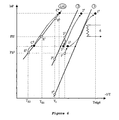
- FIGS. 4 to 7 show the position of the installation in the Clausius-Clapeyron diagram, at different phases of a cycle of operation.
- the curves on the diagrams correspond to monovariant phenomena.
- the operation of the installation would be identical if reactive phenomena were used in the reactors (1) and / or (2), corresponding, for example, to the absorption of the gas G by an absorbing solution (for example water / NH 3 , water / LiBr) or the adsorption of the G gas on the surface of an active solid (for example activated carbon or zeolite).
- an absorbing solution for example water / NH 3 , water / LiBr
- an active solid for example activated carbon or zeolite
- the elements (1), (2) and (EC) are placed at ambient temperature T 0 and are isolated from each other while keeping the valves V1 and V2 closed.
- (1) and (2) respectively contain S1 and S2.
- (EC) contains G in liquid form. S1, S2 and G are chosen so that P1 ° ⁇ P2 ° ⁇ PE °.
- the situation of the elements is represented by 1 0 , 2 0 and E 0 in the diagram of FIG. 4.
- Phase 1 Phase of first cold production
- the valve V 1 remains closed.
- the plant operates through the reactor (2) and the evaporator (EC).
- the evaporator (EC) moves from the position E 0 to E 1 and the reactor (2) from the position 20 to 2 1 .
- the evolution of the respective positions is shown in FIG. 4.
- the reactor (2) is in the synthesis position, while in the state E 1 , the evaporator (EC) is in a state of 'evaporation.
- the setting in communication of (EC) and (2) causes a sudden fall of temperature in (EC) and the temperature passes from T 0 to T E1 .
- This drop in temperature thus makes it possible firstly to rapidly freeze the water contained in a tank (not shown in FIG. 1) integrated in the wall of the evaporator. A first power peak is then observed.
- the gas released by the evaporation in (EC) is absorbed by the sorbent S2 contained in (2), which causes a rise in temperature of the reactor (2) because the sorption is strongly exothermic.
- the energy produced by the sorption in (2) is absorbed by the reactor (1) which is isolated from (EC) but in thermal contact with (2).
- the reactor (1) then constitutes a thermal capacity allowing the reactor (2) to stay away from its thermodynamic equilibrium.
- the reactor (1) then moves from the position 1 0 to the 1 1 position while remaining on its thermodynamic equilibrium line.
- Phase 2 Second cold production phase
- the reactor (2) acts as a heat capacity for the reactor (1).
- the reactor (2) which absorbs the heat of exothermic reaction from the reactor (1), rises in temperature and is placed on its thermodynamic equilibrium in 2 2 . Thanks to this thermal capacity, the reactor (1) remains in 1 2 which is a position away from its thermodynamic equilibrium, which allows a second peak of high production of cooling capacity.
- Phase 3 phase of ice removal and regeneration
- valve V 2 is opened, valve V 1 remaining open.
- the elements (1), (2) and (EC) are placed rapidly in the positions 1 3 , 2 3 and C 3 at a pressure level intermediate between that of the phases 1 and 2.
- the contents of the reactor (2) is in decomposition position and the contents of the reactor (1) remains in the synthesis position.
- the equilibrium differences in these synthesis / decomposition remain significant, because of the thermal contact that exists between the reactors (1) and (2).
- the decomposition in the reactor (2) is faster than the synthesis which ends in the reactor (1).
- a condensation is immediately engaged in the device (EC) which evolves rapidly to the position C 3 . This exothermic condensation is possible because the heat is absorbed by the superficial melting of the ice cubes, which induces their detachment thus facilitating their subsequent evacuation of the device (EC).
- the condensation is again possible, when the reactor (1) is in position 1 4 and when the condensation pressure becomes higher at the saturation vapor pressure corresponding to the average temperature of the cooling fluid of the element (EC) (for example that of the outside air).
- the temperature T 1 4 is the regeneration temperature (Treg) and the device (EC) is in position C 4 , which causes the reactor (2) in the position 2 4 also at the pressure level imposed by the condensation.
- thermodynamic position C 4 is then necessarily such that the temperature corresponding to the C 4 position is greater than the ambient temperature T 0, because of the heat transfer from condensation to the heat sink.
- the regeneration of the device implies that the extraction of heat from this exothermic condensation must take place in a heat sink, which may be ambient air or a cooling circuit.
- the evolution of the position of the different elements is shown in FIG.
- Phase 4 Cooling phase and return to the initial phase
- the enclosure (EC) further contains a phase-change material M whose temperature T M is at least slightly less than the cold production temperature T E1 in (EC) corresponding to the synthesis in (2)
- the regeneration of the sorbents contained in the reactors (1) and (2) is more fast.
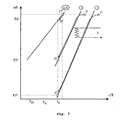
- the successive states in which the reactors (1) and (2) and the enclosure (EC) are located during the successive phases are shown in the Clausius-Clapeyron diagram shown in FIG. 8.
- the The device (EC) can have the configuration shown in FIGS. 2 and 3.
- the elements (1), (2) and (EC) are in the position represented by 1 0 , 2 0 and E 0 in FIG. 8.
- Phase 1 Phase of first cold production
- the valve V 1 remains closed.
- the plant operates through the reactor (2) and the evaporator (EC).
- the evaporator (EC) moves from the position E 0 to E 1 and the reactor (2) from the position 20 to 2 1 .
- the reactor (2) In the state 2 1 , the reactor (2) is in the synthesis position, while in the state E 1 , the evaporator (EC) is in the evaporation state.
- the setting in communication of (EC) and (2) causes a sudden drop of the temperature in (EC) which passes from T 0 to T E1 .
- This temperature drop thus makes it possible, in a first step, for the rapid cooling then the partial freezing of the water contained in the tank 7 integrated in the wall of the evaporator, then the solidification of the material M.
- the gas released by the evaporation in (EC) is absorbed by the sorbent S2 contained in (2), which causes a rise in temperature of the reactor (2) because the sorption is strongly exothermic.
- the energy produced by the sorption in (2) is absorbed by the reactor (1) which is isolated from (EC) but in thermal contact with (2).
- the reactor (1) then constitutes a thermal capacity allowing the reactor (2) to stay away from its thermodynamic equilibrium.
- the reactor 1 then passes from the position 1 0 to the position 1 1 while remaining on its thermodynamic equilibrium line.
- Phase 2 Second cold production phase
- Phase 3 phase of ice removal and regeneration
- valve V 2 is opened, valve V 1 remaining open.
- the elements (1), (2) and (EC) are placed rapidly in the positions 1 3 , 2 3 and C 3 at a pressure level intermediate between that of the phases 1 and 2.
- the contents of the reactor (2) is in decomposition position and the contents of the reactor (1) remains in the synthesis position.
- the equilibrium differences in these synthesis / decomposition remain significant, because of the thermal contact that exists between the reactors (1) and (2).
- the decomposition in the reactor (2) is faster than the synthesis which ends in the reactor (1).
- a condensation is immediately engaged in the device (EC) which evolves rapidly to the position C 3 . This exothermic condensation is possible because the heat is absorbed by the superficial melting of the ice cubes, which induces their detachment thus facilitating their subsequent evacuation of the device (EC).
- the temperature T 1 4 ' is the regeneration temperature (Treg) and the device (EC) is in the C 4' position, which causes the reactor (2) in the position 2 4 ' also at this pressure level imposed by the condensation of gas G.
- the opening of the valve V 2 , the valve V 1 remaining open, and the start of the heating means (6) in the reactor (1) triggers the rapid desorption in the reactor (2) and the detachment and the evacuation of the ice cubes, the end of the synthesis in the reactor (1) followed by the desorption in (1).
- the condensation temperature imposed on the temperature T M by the fusion of the eutectic makes it possible, on the one hand, to carry out the condensation of the gas G at a temperature below room temperature, which makes it possible to significantly reduce the thermal amplitude traversed by the device (EC) involving improved process efficiency and shorter cycle times.
- the condensation pressure P C4 is lower than the pressure P C4 obtained in the case without a phase change material, which causes a decrease in the regeneration temperature of (1), and consequently the of (2), which implies a decrease in the energy consumed for the regeneration of (1) and (2), again leading to a better process efficiency and a reduction in cycle times.
- Phase 4 Cooling phase and return to the initial phase
- the return to the temperature T 0 is carried out, for the entire installation, in a shorter time in the presence of a phase-change material, because the reactor (1) is at a higher temperature. low.
- the regeneration temperature in the reactor operating at the highest temperature is reduced, which on the one hand shortens the duration of the process and decreases energy consumption.
Landscapes
- Engineering & Computer Science (AREA)
- Physics & Mathematics (AREA)
- Mechanical Engineering (AREA)
- Thermal Sciences (AREA)
- General Engineering & Computer Science (AREA)
- Sorption Type Refrigeration Machines (AREA)
- Supports For Pipes And Cables (AREA)
- Crystals, And After-Treatments Of Crystals (AREA)
- Physical Or Chemical Processes And Apparatus (AREA)
- Transition And Organic Metals Composition Catalysts For Addition Polymerization (AREA)
- Solid-Sorbent Or Filter-Aiding Compositions (AREA)
Abstract
Description
L'invention concerne une installation et un procédé pour la production de froid par un système thermochimique, notamment pour la congélation de divers produits ou pour la production d'eau glacée.The invention relates to an installation and a method for the production of cold by a thermochemical system, in particular for the freezing of various products or for the production of ice water.
On connaît des installations de production de chaleur ou de froid basées sur des changements de phase liquide/gaz ou des sorptions renversables entre un gaz, dit gaz de travail, et un sorbant liquide ou solide. Une sorption renversable peut être une absorption d'un gaz par un liquide, une adsorption d'un gaz sur un solide, ou une réaction entre un gaz et un solide. Une sorption renversable entre un sorbant S et un gaz G est exothermique dans le sens de la synthèse S + G → SG, et endothermique dans le sens de la décomposition SG → S + G. Dans un changement de phase liquide/gaz de G, la condensation est exothermique et l'évaporation est endothermique.There are known heat or cold production facilities based on liquid / gas phase changes or reversible sorptions between a gas, said working gas, and a liquid or solid sorbent. A reversible sorption can be an absorption of a gas by a liquid, an adsorption of a gas on a solid, or a reaction between a gas and a solid. A reversible sorption between a sorbent S and a gas G is exothermic in the sense of the synthesis S + G → SG, and endothermic in the direction of the decomposition SG → S + G. In a change of phase liquid / gas of G, condensation is exothermic and evaporation is endothermic.
Ces phénomènes renversables peuvent être représentés sur le diagramme de Clausius-Clapeyron par leur droite d'équilibre ![]()
P et T étant respectivement la pression et la température, ΔH et ΔS étant respectivement l'enthalpie et l'entropie du phénomène (décomposition, synthèse, évaporation, condensation) mis en jeu, et R étant la constante des gaz parfaits.These reversible phenomena can be represented on the Clausius-Clapeyron diagram by their equilibrium line ![]()
P and T being respectively the pressure and the temperature, ΔH and ΔS being respectively the enthalpy and the entropy of the phenomenon (decomposition, synthesis, evaporation, condensation) put into play, and R being the constant of the perfect gases.
L'étape endothermique peut être mise à profit dans une installation de ce type pour congeler divers produits (notamment de l'eau pour l'obtention de glaçons) ou pour la production d'eau froide.The endothermic stage can be used in an installation of this type to freeze various products (especially water for obtaining ice cubes) or for the production of cold water.
Divers réacteurs et procédés reposant sur ces principes ont été décrits.Various reactors and processes based on these principles have been described.
Le but de la présente invention est de fournir un procédé et une installation permettant une production frigorifique volumique très élevée, par exemple de l'ordre de 200 kW/m3, avec des durées de cycles fortement réduites et des performances plus intéressantes, notamment pour la production instantanée et rapide d'eau froide, ou pour la congélation rapide de divers produits (par exemple pour la production de glaçons).The object of the present invention is to provide a method and an installation allowing a very high volume refrigeration production, for example of the order of 200 kW / m 3 , with greatly reduced cycle times and more interesting performances, particularly for instant and rapid production of cold water, or rapid freezing of various products (eg for the production of ice cubes).
Le procédé selon la présente invention pour la production de froid par un système thermochimique comprend trois phénomènes renversables mettant en oeuvre le gaz G, dans trois enceintes (EC), (1) et (2), les températures d'équilibre respectives TE(EC), TE(1) et TE(2) à une pression donnée étant telles que TE(EC) < TE(2) < TE(1), les enceintes (1) et (2) étant en contact thermique. Il est caractérisé en ce que, à partir d'un état dans lequel les trois enceintes sont à température ambiante à la même pression,
- dans une première phase, on isole l'enceinte (1), on met en communication les enceintes (EC) et (2) pour provoquer la synthèse exothermique dans (2), la chaleur formée étant absorbée par l'enceinte (1) ;
- dans une deuxième phase, on isole l'enceinte (2) et on met en communication les enceintes (EC) et (1) pour provoquer la synthèse exothermique dans (1), la chaleur formée étant absorbée par l'enceinte (2) ;
- dans une troisième phase, on met en communication les trois enceintes et on apporte de l'énergie calorifique à l'enceinte (1) pour provoquer les étapes de décomposition exothermique dans (1) et dans (2), en vue de régénérer l'installation, qu'on laisse ensuite revenir à la température ambiante.
- in a first phase, the enclosure (1) is isolated, the enclosures (EC) and (2) are put in communication to cause the exothermic synthesis in (2), the heat formed being absorbed by the enclosure (1);
- in a second phase, the enclosure (2) is isolated and the enclosures (EC) and (1) are put in communication to cause the exothermic synthesis in (1), the heat formed being absorbed by the enclosure (2);
- in a third phase, the three chambers are put into communication and heating energy is supplied to the enclosure (1) to cause the exothermic decomposition steps in (1) and (2), in order to regenerate the installation, which is then allowed to return to room temperature.
De manière plus précise :
- au cours d'une phase préliminaire, on isole les trois enceintes les unes des autres et on les place à la température ambiante, lesdites enceintes contenant respectivement SEC+G, S1 et S2 ;
- au cours d'une première phase, on met en communication les enceintes (EC) et (2), l'enceinte (1) restant isolée, pour provoquer la synthèse exothermique dans (2) et la production de froid dans l'enceinte (EC) à la température d'équilibre dans (EC) correspondant à la pression dans l'ensemble formé par (2) et (EC) ;
- au cours d'une deuxième phase, on isole l'enceinte (2) et on met en communication les enceintes (EC) et (1), pour provoquer la synthèse exothermique dans (1) et la production de froid dans l'enceinte (EC) à la température d'équilibre dans (EC) correspondant à la pression dans l'ensemble formé par (1) et (EC) ;
- au cours d'une troisième phase, on met en relation les trois enceintes pour provoquer la synthèse dans (EC) et la décomposition dans (2), et on apporte de l'énergie calorifique à (1) pour provoquer la décomposition dans (1) ;
- au cours d'une quatrième phase, on isole les trois enceintes et on les laisse refroidir jusqu'à la température ambiante.
- during a preliminary phase, the three enclosures are isolated from each other and placed at room temperature, said enclosures respectively containing SEC + G, S1 and S2;
- during a first phase, the enclosures (EC) and (2) are put in communication, the enclosure (1) remaining isolated, to cause the exothermic synthesis in (2) and the production of cold in the enclosure ( EC) at the equilibrium temperature in (EC) corresponding to the pressure in the set formed by (2) and (EC);
- during a second phase, the enclosure (2) is isolated and the enclosures (EC) and (1) are put in communication, to cause the exothermic synthesis in (1) and the production of cold in the enclosure ( EC) at the equilibrium temperature in (EC) corresponding to the pressure in the set formed by (1) and (EC);
- in a third phase, the three chambers are related to cause synthesis in (EC) and decomposition in (2), and heat energy is supplied to (1) to cause decomposition in (1). );
- during a fourth phase, the three chambers are isolated and allowed to cool to room temperature.
Le cycle de production de froid est ainsi complet.The cold production cycle is thus complete.
Le phénomène renversable dans les réacteurs (1) et (2) peut être une sorption renversable choisie parmi les réactions chimiques renversables entre le gaz G et un solide, les adsorptions du gaz G sur un solide, et les absorptions du gaz G par un liquide.The reversible phenomenon in the reactors (1) and (2) can be a reversible sorption chosen from the reversible chemical reactions between the gas G and a solid, the adsorptions of the gas G on a solid, and the absorptions of the gas G by a liquid .
Le phénomène renversable dans le dispositif (EC) peut être une sorption telle que définie ci-dessus ou un changement de phase liquide/gaz du gaz G. Les changements de phase liquide/gaz sont préférés, car ils permettent de produire du froid avec une plus grande vitesse qu'avec des sorptions, du fait de la plus faible inertie thermique du système.The reversible phenomenon in the device (EC) can be a sorption as defined above or a change in the liquid / gas phase of the gas G. The liquid / gas phase changes are preferred because they make it possible to produce cold with a higher speed than sorptions, due to the lower thermal inertia of the system.
Dans la suite du texte, "sorption" désignera une sorption renversable, "phénomène" désignera un phénomène renversable choisi parmi les sorptions et les changements de phase liquide/gaz, "changement L/G" désignera le changement de phase liquide/gaz du gaz G, "S1", "S2" et "SEC" désigneront le sorbant à l'état pauvre en gaz ou le cas échéant G à l'état gazeux respectivement dans le réacteur (1), le réacteur (2) et le dispositif (EC), "S1+G", "S2+G" et "SEC+G" désigneront le sorbant à l'état riche en gaz ou le cas échéant G à l'état liquide respectivement dans le réacteur (1), le réacteur (2) et le dispositif (EC).In the rest of the text, "sorption" means a reversible sorption, "phenomenon" will mean a reversible phenomenon selected from sorptions and phase changes liquid / gas, "L / G change" means the liquid / gas phase change of gas G, "S1", "S2" and "SEC" will mean the sorbent in the gas-poor state or, if applicable, G gaseous state respectively in the reactor (1), the reactor (2) and the device (EC), "S1 + G", "S2 + G" and "SEC + G" will designate the sorbent in the gas-rich state or where appropriate G in the liquid state respectively in the reactor (1), the reactor (2) and the device (EC).
Comme exemple de gaz G, on peut citer l'ammoniac (NH3) et ses dérivés, l'hydrogène (H2), le dioxyde de carbone (CO2), l'eau (H2O), le sulfure d' hydrogène (H2S), le méthane et d'autres gaz naturels. Comme réaction de sorption, on peut citer les réactions utilisant des ammoniacates (par exemple des chlorures, des bromures, des iodures ou des sulfates), des hydrates, des carbonates ou des hydrures.As an example of gas G, mention may be made of ammonia (NH 3 ) and its derivatives, hydrogen (H 2 ), carbon dioxide (CO 2 ), water (H 2 O), sulphide of hydrogen (H 2 S), methane and other natural gases. Sorption reactions that may be mentioned include reactions using ammoniacates (for example chlorides, bromides, iodides or sulphates), hydrates, carbonates or hydrides.
Le procédé selon la présente invention peut être mis en oeuvre à l'aide d'une installation qui comprend un élément endothermique constitué par un dispositif (EC) et un élément exothermique constitué par un réacteur (1) et un réacteur (2). Ladite installation est caractérisée en ce que:
- les réacteurs (1) et (2) sont en contact thermique, de sorte que chacun d'eux constitue une masse thermique active pour l'autre ;
- les réacteurs (1) et (2) et le dispositif (EC) sont munis de moyens permettant de les mettre sélectivement en communication ;
- le réacteur (1) et le réacteur (2) sont munis de moyens de chauffage (6) et de moyens (5) pour évacuer la chaleur ;
- au début du cycle
- * les réacteurs (1) et (2) contiennent respectivement un sorbant S1 et un sorbant S2 susceptibles de participer à une sorption renversable mettant en jeu un gaz G, la courbe d'équilibre de la sorption renversable dans (1) étant située dans un domaine de température plus élevé que celui de la courbe d'équilibre de la sorption renversable dans (2) dans le diagramme de Clapeyron ;
- * le dispositif (EC) contient un composé G susceptible de subir un changement de phase liquide/gaz ou un sorbant SEC+G riche en gaz G susceptible de participer à une sorption renversable dont la température d'équilibre est inférieure à la température d'équilibre de la sorption renversable dans le réacteur (2).
- the reactors (1) and (2) are in thermal contact, so that each of them constitutes an active thermal mass for the other;
- the reactors (1) and (2) and the device (EC) are provided with means for selectively communicating them;
- the reactor (1) and the reactor (2) are provided with heating means (6) and means (5) for evacuating heat;
- at the beginning of the cycle
- the reactors (1) and (2) respectively contain a sorbent S1 and a sorbent S2 capable of participating in a reversible sorption involving a gas G, the equilibrium curve of the reversible sorption in (1) being situated in a temperature range higher than that of the equilibrium curve of reversible sorption in (2) in the Clapeyron diagram;
- the device (EC) contains a compound G capable of undergoing a liquid / gas phase change or a G + gas-rich SEC + G sorbent capable of participating in a reversible sorption whose equilibrium temperature is below the temperature of balance of the reversible sorption in the reactor (2).
Dans un mode de réalisation particulier, le contact thermique entre les réacteurs (1) et (2) est réalisé en plaçant le réacteur (1) à l'intérieur du réacteur (2). Par exemple, les réacteurs (1) et (2) peuvent être concentriques, le réacteur (1) étant placé à l'intérieur du réacteur (2).In a particular embodiment, the thermal contact between the reactors (1) and (2) is achieved by placing the reactor (1) inside the reactor (2). For example, the reactors (1) and (2) may be concentric, the reactor (1) being placed inside the reactor (2).
Dans un autre mode de réalisation, chacun des réacteurs (1) et (2) est constitué par plusieurs plaques creuses contenant les sorbants respectifs, les plaques de l'un étant alternées avec les plaques de l'autre. L'épaisseur des plaques est typiquement de l'ordre de 1 à 3 cm.In another embodiment, each of the reactors (1) and (2) is constituted by a plurality of hollow plates containing the respective sorbents, the plates of one being alternated with the plates of the other. The thickness of the plates is typically of the order of 1 to 3 cm.
Dans une installation selon l'invention, la production de froid a lieu au niveau du dispositif (EC). Si le froid est destiné à la production de glaçons ou d'eau froide, l'installation comprend en outre un réservoir (3) contenant de l'eau en contact thermique direct avec le dispositif (EC). Si l'on veut produire des glaçons, on utilise de préférence un réservoir (3) compartimenté à la taille des glaçons souhaités. Lorsque l'installation est utilisée pour fabriquer de l'eau froide, le réservoir 3 peut être un serpentin dans lequel circule de l'eau, intégré à la paroi du dispositif (EC). Si l'installation est destinée à congeler divers produits, le réservoir (3) a la forme adéquate pour contenir et congeler correctement les produitsIn an installation according to the invention, the production of cold takes place at the level of the device (EC). If the cold is intended for the production of ice or cold water, the installation further comprises a reservoir (3) containing water in direct thermal contact with the device (EC). If it is desired to produce ice cubes, a reservoir (3) compartmentalized to the size of the desired ice cubes is preferably used. When the installation is used to produce cold water, the
La figure 1 représente un schéma d'une installation selon l'invention.Figure 1 shows a diagram of an installation according to the invention.
Sur cette figure, l'installation comprend un réacteur (1) muni de moyens de chauffage (6), un réacteur (2) en contact thermique avec le réacteur (1) et muni de moyens de refroidissement (5), un dispositif (EC), des conduites munies de vannes V1 et V2 permettant de mettre les réacteurs (1) et (2) sélectivement en contact avec (EC). Le réacteur (1) contient un sorbant S1 capable de former une sorption avec un gaz G. Le réacteur (2) contient un sorbant S2 capable de former une sorption avec le gaz G, la température d'équilibre de S1 étant supérieure à la température d'équilibre de S2 à une pression donnée. Le dispositif (EC) contient le gaz G à l'état liquide ou un sorbant SEC capable de former une sorption avec le gaz G, la température d'équilibre de SEC étant inférieure à la température d'équilibre de S2 à une pression donnée. Le dispositif (EC) est avantageusement un évaporateur/ condenseur (désigné ci-après par évaporateur) siège d'un changement de phase liquide/gaz (L/G). (EC) est en contact thermique direct avec un réservoir (3) intégré dans sa paroi et contenant de l'eau.In this figure, the installation comprises a reactor (1) provided with heating means (6), a reactor (2) in thermal contact with the reactor (1) and provided with cooling means (5), a device (EC ), pipes equipped with valves V1 and V2 to put the reactors (1) and (2) selectively in contact with (EC). The reactor (1) contains a sorbent S1 capable of forming a sorption with a gas G. The reactor (2) contains a sorbent S2 capable of forming a sorption with the gas G, the equilibrium temperature of S1 being greater than the temperature equilibrium of S2 at a given pressure. The device (EC) contains the gas G in the liquid state or a sorbent SEC capable of forming a sorption with the gas G, the SEC equilibrium temperature being lower than the equilibrium temperature of S2 at a given pressure. The device (EC) is advantageously an evaporator / condenser (hereinafter referred to as an evaporator) seat of a liquid / gas phase change (L / G). (EC) is in direct thermal contact with a reservoir (3) integrated in its wall and containing water.
L'installation et le procédé selon l'invention sont particulièrement intéressants lorsque le dispositif (2) est un évaporateur/condenseur (désigné ci-après par évaporateur). Dans un mode de réalisation particulier, l'évaporateur a une structure telle que représentée sur les figures 2 et 3. La figure 2 représente une vue en section transversale, la figure 3 représente une vue en coupe longitudinale.The installation and the method according to the invention are particularly interesting when the device (2) is an evaporator / condenser (hereinafter referred to as an evaporator). In a particular embodiment, the evaporator has a structure as shown in Figures 2 and 3. Figure 2 shows a cross-sectional view, Figure 3 shows a longitudinal sectional view.
L'évaporateur est constitué par un cylindre (8) qui est fermé à ses deux extrémités et qui a une section circulaire. La section circulaire comporte à sa partie supérieure un arc de cercle concave correspondant à la section du bac à glaçon (7). Des ailettes creuses (9) sont placées à l'intérieur de l'évaporateur, dans le sens longitudinal. Un tube (10) relié à la conduite permettant le transfert du gaz G entre l'évaporateur et les réacteurs (1) ou (2) pénètre dans l'enceinte cylindrique de l'évaporateur par un alésage réalisé dans l'une des extrémités du cylindre, et il est placé directement sous la paroi du bac à glaçons (7). Le gaz de travail G sous forme d'un liquide en ébullition est placé dans le fond de l'évaporateur. L'espace entre les parois des ailettes est occupé par le matériau à changement de phase M.The evaporator is constituted by a cylinder (8) which is closed at both ends and which has a circular section. The circular section has at its upper part a concave arc corresponding to the section of the ice cube tray (7). Hollow fins (9) are placed inside the evaporator in the longitudinal direction. A tube (10) connected to the pipe for the transfer of the gas G between the evaporator and the reactors (1) or (2) enters the cylindrical chamber of the evaporator by a bore formed in one end of the cylinder, and it is placed directly under the wall of the ice cube tray (7). The working gas G in the form of a boiling liquid is placed in the bottom of the evaporator. The space between the walls of the fins is occupied by the phase change material M.
La paroi extérieure de l'évaporateur (8) est réalisée dans un matériau ayant une diffusivité thermique élevée, c'est-à-dire une faible capacité thermique pour permettre une descente rapide de la température de paroi et une forte conductivité thermique pour permettre une formation rapide des glaçons. Un matériau à base d'aluminium par exemple, qui a une capacité thermique faible et une conductivité élevée, est approprié en raison de sa compatibilité avec l'ammoniac, qui est un gaz fréquemment utilisé dans les installations pour la production de froid à des température négatives . Les ailettes (9) augmentent la diffusion de la chaleur du liquide en ébullition vers le bac à glaçons, ainsi que la résistance mécanique de l'évaporateur. Le bac à glaçons 7 est muni de multiples cloisons transversales, placées de sorte à obtenir la forme souhaitée pour les glaçons. La forme globale du bac à glaçons possède une géométrie adaptée en demi-lune torique, ce qui permet un démoulage aisé des glaçons formés.The outer wall of the evaporator (8) is made of a material having a high thermal diffusivity, that is to say a low heat capacity to allow a rapid descent of the wall temperature and a high thermal conductivity to allow rapid formation of ice cubes. An aluminum-based material, for example, which has a low heat capacity and a high conductivity, is suitable because of its compatibility with ammonia, which is a gas frequently used in installations for the production of cold temperatures. negative. The fins (9) increase the diffusion of heat from the boiling liquid to the ice cube tray, as well as the mechanical strength of the evaporator. The
Le matériau à changement de phase M placé entre les parois des ailettes creuses maintient la température de l'évaporateur à une température basse, ce qui permet de prolonger la phase de production des glaçons pendant la phase transitoire de chauffage pour la régénération du réacteur isolé de l'évaporateur.The phase change material M placed between the walls of the hollow fins maintains the temperature of the evaporator at a low temperature, which makes it possible to extend the phase of production of the ice cubes during the transitional phase of heating for the regeneration of the reactor isolated from the evaporator.
La configuration particulière du tube (10) et sa position dans l'enceinte de l'évaporateur sont telles que les gaz chauds, provenant du réacteur lors de la phase 5 de mise en communication du réacteur à haute pression et de l'évaporateur maintenu à basse pression par le matériau à changement de phase, viennent frapper en premier lieu la paroi du bac à glaçons, ce qui facilite de décollement des glaçons.The particular configuration of the tube (10) and its position in the chamber of the evaporator are such that the hot gases from the reactor during the communication phase of the high pressure reactor and the evaporator maintained at low pressure by the phase change material, strike first the wall of the ice cube tray, which facilitates separation of ice cubes.
Dans un mode de réalisation particulier, le procédé selon l'invention pour la production de froid est mis en oeuvre à l'aide d'une installation telle que décrite ci-dessus, dans laquelle l'enceinte (EC) contient en outre un matériau à changement de phase solide/liquide M. Le matériau à changement de phase M est choisi de telle sorte que le température de solidification soit au moins légèrement inférieure à la température de production de froid dans (EC) correspondant à la synthèse dans (2). Un écart de température de quelques degrés, par exemple de 1°C à 10°C est convenable. Par exemple, cette température est de 0°C lorsque le but recherché est la fabrication de glaçons. Le matériau M peut être choisi par exemple parmi les paraffines telles que les n-alcanes ayant de 10 à 20 atomes de carbone, les mélanges eutectiques et les solutions eutectiques. Le processus se déroule de la même manière que dans le cas général décrit ci-dessus. Toutefois, lors de l'étape de régénération, la température dans l'enceinte (EC) est celle de la fusion du matériau M, induisant une température de régénération inférieure à ce qu'elle serait en l'absence du matériau à changement de phase. Cette variante de mise en oeuvre du procédé de l'invention permet par conséquent de réduire la durée d'un cycle et la quantité d'énergie requise pour la régénération.In a particular embodiment, the method according to the invention for producing cold is implemented using an installation as described above, in which the enclosure (EC) also contains a material with a solid / liquid phase change M. The phase change material M is chosen such that the solidification temperature is at least slightly lower than the cold production temperature in (EC) corresponding to the synthesis in (2) . A temperature difference of a few degrees, for example from 1 ° C to 10 ° C is suitable. For example, this temperature is 0 ° C when the goal is to make ice cubes. The material M can be chosen for example from paraffins such as n-alkanes having from 10 to 20 carbon atoms, eutectic mixtures and eutectic solutions. The process proceeds in the same manner as in the general case described above. However, during the regeneration step, the temperature in the enclosure (EC) is that of the melting of the material M, inducing a lower regeneration temperature than it would be in the absence of the phase-change material. . This alternative embodiment of the method of the invention therefore makes it possible to reduce the duration of a cycle and the amount of energy required for regeneration.
La mise en oeuvre du procédé de l'invention dans une installation selon l'invention est décrite plus en détail ci-après par référence aux figures 4 à 7, pour une installation dans laquelle (EC) est un évaporateur/ condenseur. Les figures 4 à 7 représentent la position de l'installation dans le diagramme de Clausius-Clapeyron, aux différentes phases d'un cycle de fonctionnement. Les courbes sur les diagrammes correspondent à des phénomènes monovariants. Le fonctionnement de l'installation serait toutefois identique si l'on utilisait dans les réacteurs (1) et/ou (2) un phénomène divariant, correspondant par exemple à l'absorption du gaz G par une solution absorbante (par exemple eau/NH3, eau/LiBr) ou à l' adsorption du gaz G sur la surface d'un solide actif (par exemple charbon actif ou zéolithe).The implementation of the method of the invention in an installation according to the invention is described in more detail below with reference to FIGS. 4 to 7, for an installation in which (EC) is an evaporator / condenser. Figures 4 to 7 show the position of the installation in the Clausius-Clapeyron diagram, at different phases of a cycle of operation. The curves on the diagrams correspond to monovariant phenomena. However, the operation of the installation would be identical if reactive phenomena were used in the reactors (1) and / or (2), corresponding, for example, to the absorption of the gas G by an absorbing solution (for example water / NH 3 , water / LiBr) or the adsorption of the G gas on the surface of an active solid (for example activated carbon or zeolite).
Au cours d'une phase initiale, on place les éléments (1), (2) et (EC) à la température ambiante T0 et on les isole les uns des autres en maintenant les vannes V1 et V2 fermées. Les éléments étant isolés les uns des autres, ils se trouvent à leur pression d'équilibre respective à T0, désignées par PE0, P10 et P20. (1) et (2) contiennent respectivement S1 et S2. (EC) contient G sous forme liquide. S1, S2 et G sont choisis de telle sorte que P1°< P2°< PE°. La situation des éléments est représentée par 10, 20 et E0 sur le diagramme de la figure 4.During an initial phase, the elements (1), (2) and (EC) are placed at ambient temperature T 0 and are isolated from each other while keeping the valves V1 and V2 closed. The elements being isolated from each other, they are at their respective equilibrium pressure at T 0 , designated by PE 0 , P1 0 and P2 0 . (1) and (2) respectively contain S1 and S2. (EC) contains G in liquid form. S1, S2 and G are chosen so that P1 ° <P2 ° <PE °. The The situation of the elements is represented by 1 0 , 2 0 and E 0 in the diagram of FIG. 4.
La vanne V1 reste fermée. L'installation fonctionne par le réacteur (2) et l'évaporateur (EC). L'ouverture de la vanne V2 provoque une égalisation de pression (PE1 = P21) entre (EC) et (2). L'évaporateur (EC) passe de la position E0 vers E1 et le réacteur (2) de la position 20 vers 21. L'évolution des positions respectives est représentée sur la figure 4. Dans l'état 21, le réacteur (2) est en position de synthèse, tandis que dans l'état E1, l'évaporateur (EC) est en état d'évaporation. La mise en communication de (EC) et de (2) provoque une baisse brutale de température dans (EC) et la température passe de T0 à TE1. Cette baisse de température permet ainsi dans un premier temps la congélation rapide de l'eau contenu dans un bac (non représenté sur la figure 1) intégré à la paroi de l'évaporateur. Un premier pic de puissance est alors observé. Le gaz libéré par l'évaporation dans (EC) est absorbé par le sorbant S2 contenu dans (2), ce qui provoque une montée en température du réacteur (2) du fait que la sorption est fortement exothermique. L'énergie produite par la sorption dans (2) est absorbée par le réacteur (1) qui est isolé de (EC) mais en contact thermique avec (2). Le réacteur (1) constitue alors une capacité thermique permettant au réacteur (2) de se maintenir loin de son équilibre thermodynamique. Le réacteur (1) passe alors de la position 10 vers la position 11 en restant sur sa droite d'équilibre thermodynamique.The valve V 1 remains closed. The plant operates through the reactor (2) and the evaporator (EC). The opening of the valve V 2 causes a pressure equalization (PE 1 = P2 1 ) between (EC) and (2). The evaporator (EC) moves from the position E 0 to E 1 and the reactor (2) from the position 20 to 2 1 . The evolution of the respective positions is shown in FIG. 4. In the
Lorsque la synthèse est totale dans le réacteur (2) à la fin de la phase 1 [dont la durée est déterminée par la nature et les quantités d'éléments mis en oeuvre dans (2) et (EC)], on ferme la vanne V2 et on ouvre immédiatement la vanne V1. L'installation fonctionne alors par le réacteur (1) et l'évaporateur (EC). L'équilibre de pression qui s'établit entre le réacteur (1) et l'évaporateur (EC) fait passer ces éléments des positions représentées par E1 et 11 aux positions représentées par E2 et 12. Cette évolution est représentée sur la figure 5.When the synthesis is complete in the reactor (2) at the end of phase 1 [whose duration is determined by the nature and the quantities of elements used in (2) and (EC)], the valve is closed V 2 and immediately opens the valve V 1 . The installation then runs through the reactor (1) and the evaporator (EC). The pressure equilibrium that is established between the reactor (1) and the evaporator (EC) makes these elements move from the positions represented by E 1 and 1 1 at the positions represented by E 2 and 1 2 . This evolution is represented in FIG.
Du froid est produit dans l'évaporateur (EC) en E2, c'est-à-dire à une température TE2 inférieure à la température de production de froid TE1 dans la phase 1. Du fait que les phases 1 et 2 s'effectuent à la suite l'une de l'autre, elles donnent des puissances fortes de production de froid à TE2, n'entraînant (EC) que du niveau TE 1 vers TE 2. Lors de cette phase, le réacteur (2) joue le rôle de capacité thermique pour le réacteur (1). Le réacteur (2) qui absorbe la chaleur de réaction exothermique issu du réacteur (1), monte en température et se place sur son équilibre thermodynamique en 22. Grâce cette capacité thermique, le réacteur (1) reste en 12 qui est une position éloignée de son équilibre thermodynamique, ce qui permet un second pic de forte production de puissance frigorifique.Cold is produced in the evaporator (EC) E 2 , that is to say at a temperature T E2 lower than the cold production temperature T E1 in
A la fin ou avant la fin de la phase 2, on ouvre la vanne V2, la vanne V1 restant ouverte.At the end or before the end of
Les éléments (1), (2) et (EC) se placent rapidement dans les positions 13, 23 et C3 à un niveau de pression intermédiaire entre celui des phases 1 et 2. Le contenu du réacteur (2) est en position de décomposition et le contenu du réacteur (1) reste en position de synthèse. Les écarts à l'équilibre de ces synthèse/décomposition restent importants, à cause du contact thermique qui existe entre les réacteurs (1) et (2). Il en résulte que la décomposition dans le réacteur (2) est plus rapide que la synthèse qui se termine dans le réacteur (1). Ainsi, une condensation est enclenchée immédiatement dans le dispositif (EC) qui évolue rapidement vers la position C3. Cette condensation exothermique est possible car la chaleur est absorbée par la fusion superficielle des glaçons, ce qui induit leur décollement facilitant ainsi leur évacuation ultérieure du dispositif (EC). La mise en route des moyens de chauffage (6) dans (1) dès le début de cette phase (en même temps que l'ouverture de la vanne V2), entraîne la condensation dans (EC) qui évolue progressivement de la position C3 à un niveau de pression C4 qui permette de nouveau la condensation du gaz G. La condensation est à nouveau possible, lorsque le réacteur (1) se trouve en position 14 et lorsque la pression de condensation devient supérieure à la pression de vapeur saturante correspondante à la température moyenne du fluide de refroidissement de l'élément (EC) (par exemple celle de l'air extérieur). La température T1 4 est la température de régénération (Treg) et le dispositif (EC) est en position C4, ce qui entraîne le réacteur (2) dans la position 24 également au niveau de pression imposé par la condensation. La position thermodynamique C4 est alors nécessairement telle que la température correspondante à la position C4 est supérieure à la température ambiante To, ceci en raison du transfert de chaleur de condensation vers le puits de chaleur. La régénération du dispositif implique que l'extraction de la chaleur de cette condensation exothermique doit s'effectuer dans un puits de chaleur, pouvant être l'air ambiant ou un circuit de refroidissement. L'évolution de la position des différents éléments est représentée sur la figure 6.The elements (1), (2) and (EC) are placed rapidly in the
Dès que la régénération des réacteurs (1) et (2) est terminée, on ferme les vannes V1 et V2. Les réacteurs ainsi isolés sont alors refroidis, soit naturellement, soit à l'aide des moyens de refroidissement (5) (ventilateur, circuit de refroidissement,...) provoquant une baisse de température et de pression. Chaque élément évolue selon sa courbe d'équilibre thermodynamique jusqu'à atteindre la température ambiante et retrouver ainsi le positionnement initial respectivement en E0, 10 et 20. Le dispositif se met ainsi dans les conditions initiales de la phase de stockage de la production de froid du début du cycle de fonctionnement. L'évolution de la position des différents éléments au cours de cette phase est représentée sur la figure 7.As soon as the regeneration of the reactors (1) and (2) is complete, the valves V1 and V2 are closed. The reactors thus isolated are then cooled, either naturally or using the cooling means (5) (fan, cooling circuit, ...) causing a drop in temperature and pressure. Each element evolves according to its thermodynamic equilibrium curve until reaching the ambient temperature and thus find the initial positioning respectively in E 0 , 1 0 and 2 0 . The device is thus in the initial conditions of the storage phase of the cold production of the beginning of the operating cycle. The evolution of the position of the various elements during this phase is shown in FIG.
Lorsque le procédé de l'invention est mis en oeuvre avec une installation dans laquelle l'enceinte (EC) contient en outre un matériau à changement de phase M dont la température de changement de phase TM est au moins légèrement inférieure à la température de production de froid TE1 dans (EC) correspondant à la synthèse dans (2), la régénération des sorbants contenus dans les réacteurs (1) et (2) est plus rapide. Les états successifs dans lesquels se trouvent les réacteurs (1) et (2) et l'enceinte (EC) au cours des phases successives sont montrés sur le diagramme de Clausius-Clapeyron représenté sur la figure 8. Dans ce mode de réalisation, le dispositif (EC) peut avoir la configuration représentée sur les figures 2 et 3.When the process of the invention is implemented with an installation in which the enclosure (EC) further contains a phase-change material M whose temperature T M is at least slightly less than the cold production temperature T E1 in (EC) corresponding to the synthesis in (2), the regeneration of the sorbents contained in the reactors (1) and (2) is more fast. The successive states in which the reactors (1) and (2) and the enclosure (EC) are located during the successive phases are shown in the Clausius-Clapeyron diagram shown in FIG. 8. In this embodiment, the The device (EC) can have the configuration shown in FIGS. 2 and 3.
Elle est analogue à la phase initiale décrite ci-dessus. Les éléments (1), (2) et (EC) sont dans la position représentée par 10, 20 et E0 sur la figure 8.It is analogous to the initial phase described above. The elements (1), (2) and (EC) are in the position represented by 1 0 , 2 0 and E 0 in FIG. 8.
La vanne V1 reste fermée. L'installation fonctionne par le réacteur (2) et l'évaporateur (EC). L'ouverture de la vanne V2 provoque une égalisation de pression (PE1 = P21) entre (EC) et (2). L'évaporateur (EC) passe de la position E0 vers E1 et le réacteur (2) de la position 20 vers 21. Dans l'état 21, le réacteur (2) est en position de synthèse, tandis que dans l'état E1, l'évaporateur (EC) est en état d'évaporation.The valve V 1 remains closed. The plant operates through the reactor (2) and the evaporator (EC). The opening of the valve V 2 causes a pressure equalization (PE 1 = P2 1 ) between (EC) and (2). The evaporator (EC) moves from the position E 0 to E 1 and the reactor (2) from the position 20 to 2 1 . In the
La mise en communication de (EC) et de (2) provoque une baisse brutale de la température dans (EC) qui passe de T0 à TE1. Cette baisse de température permet ainsi dans un premier temps le refroidissement rapide puis la congélation partielle de l'eau contenu dans le bac 7 intégré à la paroi de l'évaporateur, puis la solidification du matériau M. Le gaz libéré par l'évaporation dans (EC) est absorbé par le sorbant S2 contenu dans (2), ce qui provoque une montée en température du réacteur (2) du fait que la sorption est fortement exothermique. L'énergie produite par la sorption dans (2) est absorbée par le réacteur (1) qui est isolé de (EC) mais en contact thermique avec (2). Le réacteur (1) constitue alors une capacité thermique permettant au réacteur (2) de se maintenir loin de son équilibre thermodynamique. Le réacteur 1 passe alors de la position 10 vers la position 11 en restant sur sa droite d'équilibre thermodynamique.The setting in communication of (EC) and (2) causes a sudden drop of the temperature in (EC) which passes from T 0 to T E1 . This temperature drop thus makes it possible, in a first step, for the rapid cooling then the partial freezing of the water contained in the
La présence d'un matériau à changement de phase dans (EC) ne modifie pas le déroulement de la phase 2. A la fin de cette phase, les réacteurs (1) et (2) et l'enceinte (EC) se trouvent dans les positions respectives 12, 22, E2.The presence of a phase change material in (EC) does not modify the course of
A la fin dé la phase 2, on ouvre la vanne V2, la vanne V1 restant ouverte.At the end of
Les éléments (1), (2) et (EC) se placent rapidement dans les positions 13, 23 et C3 à un niveau de pression intermédiaire entre celui des phases 1 et 2. Le contenu du réacteur (2) est en position de décomposition et le contenu du réacteur (1) reste en position de synthèse. Les écarts à l'équilibre de ces synthèse/décomposition restent importants, à cause du contact thermique qui existe entre les réacteurs (1) et (2). Il en résulte que la décomposition dans le réacteur (2) est plus rapide que la synthèse qui se termine dans le réacteur (1). Ainsi, une condensation est enclenchée immédiatement dans le dispositif (EC) qui évolue rapidement vers la position C3. Cette condensation exothermique est possible car la chaleur est absorbée par la fusion superficielle des glaçons, ce qui induit leur décollement facilitant ainsi leur évacuation ultérieure du dispositif (EC). La mise en route des moyens de chauffage (6) dans (1) dès le début de cette phase (en même temps que l'ouverture de la vanne V2), entretient la condensation dans (EC) qui continue d'évoluer progressivement de la position C3 à la position C4' permettant de nouveau d'obtenir une condensation effective du gaz. La condensation est à nouveau possible, lorsque le réacteur (1) se trouve en position 14' et lorsque la pression de condensation devient supérieure à la pression de vapeur saturante correspondante à la température TM de fusion du matériau à changement de phase. La température T1 4' est la température de régénération (Treg) et le dispositif (EC) est en position C4', ce qui entraîne le réacteur (2) dans la position 24' également à ce niveau de pression imposé par la condensation du gaz G.The elements (1), (2) and (EC) are placed rapidly in the
L'ouverture de la vanne V2, la vanne V1 restant ouverte, et la mise en route des moyens de chauffage (6) dans le réacteur (1) déclenche la désorption rapide dans le réacteur (2) et le décollement et de l'évacuation des glaçons, la fin de la synthèse dans le réacteur (1) suivie de la désorption dans (1). La température de condensation imposée à la température TM par la fusion de l'eutectique permet d'une part de réaliser la condensation du gaz G à une température inférieure à la température ambiante ce qui permet de diminuer nettement l'amplitude thermique parcourue par le dispositif (EC) impliquant une meilleur efficacité du procédé et des durées de cycles plus courts. D'autres part, la pression de condensation PC4, est plus faible que la pression PC4 obtenu dans le cas sans matériau à changement de phase ce qui entraîne une diminution de la température de régénération de (1), et par conséquent de celle de (2), ce qui implique une diminution de l'énergie consommée pour la régénération de (1) et de (2) entraînant là encore une meilleure efficacité du procédé et une réduction des temps de cycles.The opening of the valve V 2 , the valve V 1 remaining open, and the start of the heating means (6) in the reactor (1) triggers the rapid desorption in the reactor (2) and the detachment and the evacuation of the ice cubes, the end of the synthesis in the reactor (1) followed by the desorption in (1). The condensation temperature imposed on the temperature T M by the fusion of the eutectic makes it possible, on the one hand, to carry out the condensation of the gas G at a temperature below room temperature, which makes it possible to significantly reduce the thermal amplitude traversed by the device (EC) involving improved process efficiency and shorter cycle times. On the other hand, the condensation pressure P C4 is lower than the pressure P C4 obtained in the case without a phase change material, which causes a decrease in the regeneration temperature of (1), and consequently the of (2), which implies a decrease in the energy consumed for the regeneration of (1) and (2), again leading to a better process efficiency and a reduction in cycle times.
Le retour à la température T0 s'effectue, pour l'ensemble de l'installation, en un temps plus court en présence d'un matériau à changement de phase, du fait que le réacteur (1) se trouve à une température plus basse.The return to the temperature T 0 is carried out, for the entire installation, in a shorter time in the presence of a phase-change material, because the reactor (1) is at a higher temperature. low.
L'installation selon l'invention dans sa configuration la plus générale, gérée par le procédé de l'invention, permet ainsi de produire du froid de forte puissance sur des durées très courtes, qui peuvent permettre la production quasi-instantanée de glaçons par exemple. En outre, lorsque l'installation contient un matériau à changement de phase dans l'élément endothermique, la température de régénération dans le réacteur fonctionnant à la température la plus élevée est diminuée, ce qui d'une part raccourcit la durée du processus et diminue la consommation d'énergie.The installation according to the invention in its most general configuration, managed by the process of the invention, thus makes it possible to produce high power cold over very short periods of time, which can allow the almost instant production of ice cubes for example. . In addition, when the plant contains a phase change material in the endothermic element, the regeneration temperature in the reactor operating at the highest temperature is reduced, which on the one hand shortens the duration of the process and decreases energy consumption.
Claims (13)
- A method of refrigeration using a thermochemical system which comprises three reversible phenomena involving the gas G in three chambers (EC), (1) and (2), the respective equilibrium temperatures TE(EC), TE(1) and TE(2) at a given pressure being such that TE(EC)<TE(2)<TE(1), the chambers (1) and (2) being in thermal contact, characterized in that, starting from a state in which the three chambers are at ambient temperature and at the same pressure:- in a first step, the chamber (1) is isolated and the chambers (EC) and (2) are brought into communication in order to carry out the exothermic synthesis in (2), the heat produced being absorbed by the chamber (1);- in a second step, the chamber (2) is isolated and the chambers (EC) and (1) are brought into communication in order to carry out the exothermic synthesis in (1), the heat produced being absorbed by the chamber (2); and- in a third step, the three chambers are brought into communication and thermal energy is supplied to the chamber (1) in order to carry out the exothermic decomposition steps in (1) and in (2), for the purpose of regenerating the installation, which is then left to return to the ambient temperature.
- The method as claimed in claim 1, characterized in that:- in the initial state, the chambers (EC), (1) and (2) are isolated from one another and placed at the ambient temperature, the chambers (1) and (2) contain their respective sorbent S1 and S2 in the state lean in gas G, and the chamber (EC) contains G in the liquid state or the sorbent in the state rich in gas G;- during the first step, bringing the chambers (EC) and (2) into communication causes refrigeration in the chamber (EC) at the equilibrium temperature in (EC) corresponding to the pressure in the assembly formed by (2) and (EC);- during the second step, bringing the chambers (EC) and (1) into communication causes refrigeration in the chamber (EC) at the equilibrium temperature in (EC) corresponding to the pressure in the assembly formed by (1) and (EC); and- during the third step, bringing the three chambers into communication causes synthesis in (EC) and decomposition in (2), and then applying thermal energy to (1) causes decomposition in (1).
- The method as claimed in claim 1, characterized in that the reversible phenomenon in the reactors (1) and (2) is selected from reversible chemical reactions between the gas G and a solid, adsorptions of the gas G on a solid, and absorptions of the gas G by a liquid.
- The method as claimed in claim 1, characterized in that the reversible phenomenon in the device (EC) is a liquid/gas phase change.
- The method as claimed in claim 1, characterized in that the reversible phenomenon in the device (EC) is a sorption chosen from reversible chemical reactions between the gas G and a solid, adsorptions of the gas G on a solid, and absorptions of the gas G by a liquid.
- An installation for implementing the method as claimed in claim 1, comprising an endothermic component consisting of a device (EC) and an exothermic component consisting of a reactor (1) and a reactor (2) in thermal contact so that each of them constitutes an active thermal mass for the other, characterized in that :- the reactors (1) and (2) and the device (EC) are provided with means for bringing them selectively into communication;- the reactor (1) and the reactor (2) are provided with heating means (6) and heat extraction means (5); and- at the start of a cycle:* the reactors (1) and (2) contain a sorbent S1 and a sorbent S2, respectively, capable of participating in a reversible sorption involving a gas G, the equilibrium temperature of the reversible sorption in (1) being higher than the equilibrium temperature of the reversible sorption in (2) at a given pressure; and* the device (EC) contains a compound G capable of undergoing a liquid/gas phase change or an SEC+G sorbent rich in gas G capable of participating in a reversible sorption, the equilibrium temperature of which is below the equilibrium temperature of the reversible sorption in the reactor (2).
- The installation as claimed in claim 6, characterized in that the device (EC) is in direct thermal contact with a reservoir (3) containing water.
- The installation as claimed in claim 6, characterized in that the device (EC) furthermore contains a liquid/solid phase change material, the phase change temperature of which is below the refrigeration temperature.
- The installation as claimed in claim 6, characterized in that the device (EC) is an evaporator which consists of a cylinder (8) which is closed at its two ends, the circular cross section of which cylinder includes, in its upper part, a concave circular arc corresponding to the cross section of the ice tray (7), which evaporator furthermore includes:- hollow fins (9) are placed inside the cylinder, in longitudinal direction, the space between the hollow fins being occupied by a solid/liquid phase change material;- a tube (10), connected to a pipe transferring the gas G between the evaporator and the reactor (2), runs into the cylindrical chamber of the evaporator via a bore made in one of the ends of the cylinder, which tube is placed directly beneath the wall of the ice tray (7), the working gas G in the form of a boiling liquid being placed in the bottom of the evaporator.
- The installation as claimed in claim 6, characterized in that the reactor (1) is placed inside the reactor (2).
- The installation as claimed in claim 10, characterized in that the reactors (1) and (2) are concentric, the reactor (1) being placed inside the reactor (2).
- The installation as claimed in claim 6, characterized in that each of the reactors (1) and (2) is formed by several hollow plates containing the respective sorbents, the plates of one reactor alternating with the plates of the other.
- The installation as claimed in claim 8, characterized in that the difference between the phase change temperature of the phase change material and the refrigeration temperature is from 1°C to 10°C.
Applications Claiming Priority (3)
| Application Number | Priority Date | Filing Date | Title |
|---|---|---|---|
| FR0209392A FR2842892B1 (en) | 2002-07-24 | 2002-07-24 | INSTALLATION AND METHOD FOR THE PRODUCTION OF COLD BY A REVERSAL SORPTION SYSTEM |
| FR0209392 | 2002-07-24 | ||
| PCT/FR2003/002218 WO2004011860A2 (en) | 2002-07-24 | 2003-07-11 | Method for producing cold and installation therefor |
Publications (2)
| Publication Number | Publication Date |
|---|---|
| EP1523643A2 EP1523643A2 (en) | 2005-04-20 |
| EP1523643B1 true EP1523643B1 (en) | 2007-09-12 |
Family
ID=30011446
Family Applications (1)
| Application Number | Title | Priority Date | Filing Date |
|---|---|---|---|
| EP03771135A Expired - Lifetime EP1523643B1 (en) | 2002-07-24 | 2003-07-11 | Method for producing cold and installation therefor |
Country Status (10)
| Country | Link |
|---|---|
| US (1) | US7621149B2 (en) |
| EP (1) | EP1523643B1 (en) |
| JP (1) | JP4335134B2 (en) |
| AT (1) | ATE373212T1 (en) |
| AU (1) | AU2003264716A1 (en) |
| DE (1) | DE60316295T2 (en) |
| ES (1) | ES2293038T3 (en) |
| FR (1) | FR2842892B1 (en) |
| PT (1) | PT1523643E (en) |
| WO (1) | WO2004011860A2 (en) |
Families Citing this family (3)
| Publication number | Priority date | Publication date | Assignee | Title |
|---|---|---|---|---|
| FR2877425B1 (en) * | 2004-11-04 | 2007-01-19 | Techn Ice Sarl | COLD PRODUCTION AT VERY LOW TEMPERATURE IN A THERMOCHEMICAL DEVICE. |
| FR3071046B1 (en) * | 2017-09-11 | 2020-01-10 | Coldway | REFRIGERATION PLANT OF AN INSULATED BOX UP TO A TARGET TEMPERATURE - ASSOCIATED METHOD |
| GB2571298A (en) * | 2018-02-22 | 2019-08-28 | Differ As | Cooking apparatus |
Family Cites Families (15)
| Publication number | Priority date | Publication date | Assignee | Title |
|---|---|---|---|---|
| US3044861A (en) * | 1958-02-27 | 1962-07-17 | Carbonic Dev Corp | Regenerative apparatus |
| FR2615601B1 (en) * | 1987-05-22 | 1989-11-10 | Faiveley Ets | DEVICE AND METHOD FOR PRODUCING COLD AND / OR HEAT BY SOLID-GAS REACTION |
| JPH02122169A (en) * | 1988-11-01 | 1990-05-09 | Hitachi Ltd | chemical heat pump |
| FR2723438B1 (en) * | 1994-08-02 | 1996-09-20 | Lorraine Carbone | IMPROVED POWER CHEMICAL HEAT PUMP REACTOR |
| US5492777A (en) * | 1995-01-25 | 1996-02-20 | Westinghouse Electric Corporation | Electrochemical energy conversion and storage system |
| FR2748093B1 (en) * | 1996-04-25 | 1998-06-12 | Elf Aquitaine | THERMOCHEMICAL DEVICE TO PRODUCE COLD AND / OR HEAT |
| FR2749377B1 (en) * | 1996-05-30 | 1998-07-10 | Elf Aquitaine | METHOD FOR MANAGING A THERMOCHEMICAL REACTION OR SOLID-GAS ADSORPTION |
| PL191124B1 (en) * | 1997-10-08 | 2006-03-31 | Shell Int Research | Process heater with a flameless chamber |
| US6528026B2 (en) * | 1998-08-13 | 2003-03-04 | Symyx Technologies, Inc. | Multi-temperature modular reactor and method of using same |
| US6306658B1 (en) * | 1998-08-13 | 2001-10-23 | Symyx Technologies | Parallel reactor with internal sensing |
| US6402369B1 (en) * | 1998-11-03 | 2002-06-11 | Sarnoff Corporation | Arrayable thermal assays |
| US6641625B1 (en) * | 1999-05-03 | 2003-11-04 | Nuvera Fuel Cells, Inc. | Integrated hydrocarbon reforming system and controls |
| WO2002035618A1 (en) * | 2000-10-20 | 2002-05-02 | Rayovac Corporation | Method and apparatus for regulating charging of electrochemical cells |
| US6811913B2 (en) * | 2000-11-15 | 2004-11-02 | Technology Management, Inc. | Multipurpose reversible electrochemical system |
| US6553771B2 (en) * | 2000-12-01 | 2003-04-29 | Borst Inc. | Electrochemical heat pump system |
-
2002
- 2002-07-24 FR FR0209392A patent/FR2842892B1/en not_active Expired - Fee Related
-
2003
- 2003-07-11 AT AT03771135T patent/ATE373212T1/en not_active IP Right Cessation
- 2003-07-11 AU AU2003264716A patent/AU2003264716A1/en not_active Abandoned
- 2003-07-11 WO PCT/FR2003/002218 patent/WO2004011860A2/en not_active Ceased
- 2003-07-11 DE DE60316295T patent/DE60316295T2/en not_active Expired - Lifetime
- 2003-07-11 ES ES03771135T patent/ES2293038T3/en not_active Expired - Lifetime
- 2003-07-11 JP JP2004523848A patent/JP4335134B2/en not_active Expired - Fee Related
- 2003-07-11 EP EP03771135A patent/EP1523643B1/en not_active Expired - Lifetime
- 2003-07-11 US US10/521,760 patent/US7621149B2/en not_active Expired - Fee Related
- 2003-07-11 PT PT03771135T patent/PT1523643E/en unknown
Also Published As
| Publication number | Publication date |
|---|---|
| EP1523643A2 (en) | 2005-04-20 |
| ES2293038T3 (en) | 2008-03-16 |
| JP4335134B2 (en) | 2009-09-30 |
| DE60316295T2 (en) | 2008-06-12 |
| FR2842892A1 (en) | 2004-01-30 |
| AU2003264716A1 (en) | 2004-02-16 |
| US20060090476A1 (en) | 2006-05-04 |
| WO2004011860A2 (en) | 2004-02-05 |
| ATE373212T1 (en) | 2007-09-15 |
| AU2003264716A8 (en) | 2004-02-16 |
| JP2005533993A (en) | 2005-11-10 |
| DE60316295D1 (en) | 2007-10-25 |
| US7621149B2 (en) | 2009-11-24 |
| FR2842892B1 (en) | 2005-03-18 |
| PT1523643E (en) | 2007-11-26 |
| WO2004011860A3 (en) | 2004-07-29 |
Similar Documents
| Publication | Publication Date | Title |
|---|---|---|
| EP0622593A1 (en) | Cooling and heating device using a solid sorbent | |
| EP2499418A1 (en) | Hydrogen storage tank having metal hydrides | |
| FR2952695A1 (en) | METAL HYDRIDE HYDROGEN STORAGE TANK | |
| FR2703763A1 (en) | Chemical reactor, refrigerating machine and container thus equipped, and reagent cartridge thereto. | |
| EP1290387B1 (en) | Method for making a self-refrigerating drink package and equipment therefor | |
| EP1523643B1 (en) | Method for producing cold and installation therefor | |
| EP1529185B1 (en) | Installation and method for producing cold by a reversible sorption system | |
| EP1608920B1 (en) | Method and device for rapid and high- power cold production | |
| EP0810410B1 (en) | Method of controlling a thermochemical reaction or a solid-gas adsorption | |
| FR2666875A1 (en) | Refrigeration machine with adsorption/desorption on zeolite using exchangers made of profiled aluminium sections | |
| EP3027979B1 (en) | Compact thermochemical reactor with optimised transfers and maintenance | |
| EP3368852B1 (en) | Device for storing thermal energy by a solid-liquid phase-change material comprising a condenser | |
| CA2168944A1 (en) | Controlled temperature dual phase heat exchanger | |
| WO2016051076A1 (en) | Method for getting the inside of a thermally insulated space up to temperature and maintaining it at temperature without the provision of continuous energy, and associated device | |
| EP3682176B1 (en) | Method for refrigerating an isothermal box to a target temperature and associated facility |
Legal Events
| Date | Code | Title | Description |
|---|---|---|---|
| PUAI | Public reference made under article 153(3) epc to a published international application that has entered the european phase |
Free format text: ORIGINAL CODE: 0009012 |
|
| 17P | Request for examination filed |
Effective date: 20041223 |
|
| AK | Designated contracting states |
Kind code of ref document: A2 Designated state(s): AT BE BG CH CY CZ DE DK EE ES FI FR GB GR HU IE IT LI LU MC NL PT RO SE SI SK TR |
|
| AX | Request for extension of the european patent |
Extension state: AL LT LV MK |
|
| DAX | Request for extension of the european patent (deleted) | ||
| RAP1 | Party data changed (applicant data changed or rights of an application transferred) |
Owner name: CENTRE NATIONAL DE LA RECHERCHE SCIENTIFIQUE |
|
| 17Q | First examination report despatched |
Effective date: 20060816 |
|
| RIN1 | Information on inventor provided before grant (corrected) |
Inventor name: NEVEU, PIERRE Inventor name: STITOU, DRISS Inventor name: SPINNER, BERNARD |
|
| GRAP | Despatch of communication of intention to grant a patent |
Free format text: ORIGINAL CODE: EPIDOSNIGR1 |
|
| GRAS | Grant fee paid |
Free format text: ORIGINAL CODE: EPIDOSNIGR3 |
|
| GRAA | (expected) grant |
Free format text: ORIGINAL CODE: 0009210 |
|
| AK | Designated contracting states |
Kind code of ref document: B1 Designated state(s): AT BE BG CH CY CZ DE DK EE ES FI FR GB GR HU IE IT LI LU MC NL PT RO SE SI SK TR |
|
| REG | Reference to a national code |
Ref country code: GB Ref legal event code: FG4D Free format text: NOT ENGLISH |
|
| REG | Reference to a national code |
Ref country code: CH Ref legal event code: EP |
|
| REF | Corresponds to: |
Ref document number: 60316295 Country of ref document: DE Date of ref document: 20071025 Kind code of ref document: P |
|
| REG | Reference to a national code |
Ref country code: IE Ref legal event code: FG4D Free format text: LANGUAGE OF EP DOCUMENT: FRENCH |
|
| REG | Reference to a national code |
Ref country code: PT Ref legal event code: SC4A Free format text: AVAILABILITY OF NATIONAL TRANSLATION Effective date: 20071113 |
|
| GBT | Gb: translation of ep patent filed (gb section 77(6)(a)/1977) |
Effective date: 20071219 |
|
| PG25 | Lapsed in a contracting state [announced via postgrant information from national office to epo] |
Ref country code: FI Free format text: LAPSE BECAUSE OF FAILURE TO SUBMIT A TRANSLATION OF THE DESCRIPTION OR TO PAY THE FEE WITHIN THE PRESCRIBED TIME-LIMIT Effective date: 20070912 |
|
| PG25 | Lapsed in a contracting state [announced via postgrant information from national office to epo] |
Ref country code: AT Free format text: LAPSE BECAUSE OF FAILURE TO SUBMIT A TRANSLATION OF THE DESCRIPTION OR TO PAY THE FEE WITHIN THE PRESCRIBED TIME-LIMIT Effective date: 20070912 |
|
| NLV1 | Nl: lapsed or annulled due to failure to fulfill the requirements of art. 29p and 29m of the patents act | ||
| REG | Reference to a national code |
Ref country code: ES Ref legal event code: FG2A Ref document number: 2293038 Country of ref document: ES Kind code of ref document: T3 |
|
| PG25 | Lapsed in a contracting state [announced via postgrant information from national office to epo] |
Ref country code: NL Free format text: LAPSE BECAUSE OF FAILURE TO SUBMIT A TRANSLATION OF THE DESCRIPTION OR TO PAY THE FEE WITHIN THE PRESCRIBED TIME-LIMIT Effective date: 20070912 Ref country code: GR Free format text: LAPSE BECAUSE OF FAILURE TO SUBMIT A TRANSLATION OF THE DESCRIPTION OR TO PAY THE FEE WITHIN THE PRESCRIBED TIME-LIMIT Effective date: 20071213 |
|
| REG | Reference to a national code |
Ref country code: IE Ref legal event code: FD4D |
|
| PG25 | Lapsed in a contracting state [announced via postgrant information from national office to epo] |
Ref country code: SK Free format text: LAPSE BECAUSE OF FAILURE TO SUBMIT A TRANSLATION OF THE DESCRIPTION OR TO PAY THE FEE WITHIN THE PRESCRIBED TIME-LIMIT Effective date: 20070912 Ref country code: CZ Free format text: LAPSE BECAUSE OF FAILURE TO SUBMIT A TRANSLATION OF THE DESCRIPTION OR TO PAY THE FEE WITHIN THE PRESCRIBED TIME-LIMIT Effective date: 20070912 |
|
| PG25 | Lapsed in a contracting state [announced via postgrant information from national office to epo] |
Ref country code: SE Free format text: LAPSE BECAUSE OF FAILURE TO SUBMIT A TRANSLATION OF THE DESCRIPTION OR TO PAY THE FEE WITHIN THE PRESCRIBED TIME-LIMIT Effective date: 20071212 Ref country code: RO Free format text: LAPSE BECAUSE OF FAILURE TO SUBMIT A TRANSLATION OF THE DESCRIPTION OR TO PAY THE FEE WITHIN THE PRESCRIBED TIME-LIMIT Effective date: 20070912 |
|
| PLBE | No opposition filed within time limit |
Free format text: ORIGINAL CODE: 0009261 |
|
| STAA | Information on the status of an ep patent application or granted ep patent |
Free format text: STATUS: NO OPPOSITION FILED WITHIN TIME LIMIT |
|
| PG25 | Lapsed in a contracting state [announced via postgrant information from national office to epo] |
Ref country code: DK Free format text: LAPSE BECAUSE OF FAILURE TO SUBMIT A TRANSLATION OF THE DESCRIPTION OR TO PAY THE FEE WITHIN THE PRESCRIBED TIME-LIMIT Effective date: 20070912 |
|
| 26N | No opposition filed |
Effective date: 20080613 |
|
| PG25 | Lapsed in a contracting state [announced via postgrant information from national office to epo] |
Ref country code: IE Free format text: LAPSE BECAUSE OF FAILURE TO SUBMIT A TRANSLATION OF THE DESCRIPTION OR TO PAY THE FEE WITHIN THE PRESCRIBED TIME-LIMIT Effective date: 20070912 |
|
| PG25 | Lapsed in a contracting state [announced via postgrant information from national office to epo] |
Ref country code: MC Free format text: LAPSE BECAUSE OF NON-PAYMENT OF DUE FEES Effective date: 20080731 |
|
| PG25 | Lapsed in a contracting state [announced via postgrant information from national office to epo] |
Ref country code: EE Free format text: LAPSE BECAUSE OF FAILURE TO SUBMIT A TRANSLATION OF THE DESCRIPTION OR TO PAY THE FEE WITHIN THE PRESCRIBED TIME-LIMIT Effective date: 20070912 |
|
| PG25 | Lapsed in a contracting state [announced via postgrant information from national office to epo] |
Ref country code: SI Free format text: LAPSE BECAUSE OF FAILURE TO SUBMIT A TRANSLATION OF THE DESCRIPTION OR TO PAY THE FEE WITHIN THE PRESCRIBED TIME-LIMIT Effective date: 20070912 |
|
| PG25 | Lapsed in a contracting state [announced via postgrant information from national office to epo] |
Ref country code: CY Free format text: LAPSE BECAUSE OF FAILURE TO SUBMIT A TRANSLATION OF THE DESCRIPTION OR TO PAY THE FEE WITHIN THE PRESCRIBED TIME-LIMIT Effective date: 20070912 |
|
| PG25 | Lapsed in a contracting state [announced via postgrant information from national office to epo] |
Ref country code: BG Free format text: LAPSE BECAUSE OF FAILURE TO SUBMIT A TRANSLATION OF THE DESCRIPTION OR TO PAY THE FEE WITHIN THE PRESCRIBED TIME-LIMIT Effective date: 20071212 |
|
| PG25 | Lapsed in a contracting state [announced via postgrant information from national office to epo] |
Ref country code: HU Free format text: LAPSE BECAUSE OF FAILURE TO SUBMIT A TRANSLATION OF THE DESCRIPTION OR TO PAY THE FEE WITHIN THE PRESCRIBED TIME-LIMIT Effective date: 20080313 Ref country code: LU Free format text: LAPSE BECAUSE OF NON-PAYMENT OF DUE FEES Effective date: 20080711 Ref country code: BE Free format text: LAPSE BECAUSE OF NON-PAYMENT OF DUE FEES Effective date: 20080731 |
|
| PG25 | Lapsed in a contracting state [announced via postgrant information from national office to epo] |
Ref country code: TR Free format text: LAPSE BECAUSE OF FAILURE TO SUBMIT A TRANSLATION OF THE DESCRIPTION OR TO PAY THE FEE WITHIN THE PRESCRIBED TIME-LIMIT Effective date: 20070912 |
|
| REG | Reference to a national code |
Ref country code: FR Ref legal event code: PLFP Year of fee payment: 14 |
|
| REG | Reference to a national code |
Ref country code: FR Ref legal event code: PLFP Year of fee payment: 15 |
|
| REG | Reference to a national code |
Ref country code: FR Ref legal event code: PLFP Year of fee payment: 16 |
|
| PGFP | Annual fee paid to national office [announced via postgrant information from national office to epo] |
Ref country code: PT Payment date: 20200616 Year of fee payment: 18 |
|
| PGFP | Annual fee paid to national office [announced via postgrant information from national office to epo] |
Ref country code: GB Payment date: 20200722 Year of fee payment: 18 Ref country code: FR Payment date: 20200731 Year of fee payment: 18 Ref country code: ES Payment date: 20200817 Year of fee payment: 18 Ref country code: DE Payment date: 20200716 Year of fee payment: 18 |
|
| PGFP | Annual fee paid to national office [announced via postgrant information from national office to epo] |
Ref country code: CH Payment date: 20200722 Year of fee payment: 18 Ref country code: IT Payment date: 20200710 Year of fee payment: 18 |
|
| REG | Reference to a national code |
Ref country code: DE Ref legal event code: R119 Ref document number: 60316295 Country of ref document: DE |
|
| REG | Reference to a national code |
Ref country code: CH Ref legal event code: PL |
|
| GBPC | Gb: european patent ceased through non-payment of renewal fee |
Effective date: 20210711 |
|
| PG25 | Lapsed in a contracting state [announced via postgrant information from national office to epo] |
Ref country code: LI Free format text: LAPSE BECAUSE OF NON-PAYMENT OF DUE FEES Effective date: 20210731 Ref country code: GB Free format text: LAPSE BECAUSE OF NON-PAYMENT OF DUE FEES Effective date: 20210711 Ref country code: DE Free format text: LAPSE BECAUSE OF NON-PAYMENT OF DUE FEES Effective date: 20220201 Ref country code: CH Free format text: LAPSE BECAUSE OF NON-PAYMENT OF DUE FEES Effective date: 20210731 |
|
| PG25 | Lapsed in a contracting state [announced via postgrant information from national office to epo] |
Ref country code: PT Free format text: LAPSE BECAUSE OF NON-PAYMENT OF DUE FEES Effective date: 20220111 Ref country code: FR Free format text: LAPSE BECAUSE OF NON-PAYMENT OF DUE FEES Effective date: 20210731 |
|
| PG25 | Lapsed in a contracting state [announced via postgrant information from national office to epo] |
Ref country code: IT Free format text: LAPSE BECAUSE OF NON-PAYMENT OF DUE FEES Effective date: 20210711 |
|
| REG | Reference to a national code |
Ref country code: ES Ref legal event code: FD2A Effective date: 20220830 |
|
| PG25 | Lapsed in a contracting state [announced via postgrant information from national office to epo] |
Ref country code: ES Free format text: LAPSE BECAUSE OF NON-PAYMENT OF DUE FEES Effective date: 20210712 |