EP2741829B1 - Sprinkler system and installation - Google Patents
Sprinkler system and installation Download PDFInfo
- Publication number
- EP2741829B1 EP2741829B1 EP12822047.2A EP12822047A EP2741829B1 EP 2741829 B1 EP2741829 B1 EP 2741829B1 EP 12822047 A EP12822047 A EP 12822047A EP 2741829 B1 EP2741829 B1 EP 2741829B1
- Authority
- EP
- European Patent Office
- Prior art keywords
- conduit
- escutcheon
- sleeve
- opening
- substrate
- Prior art date
- Legal status (The legal status is an assumption and is not a legal conclusion. Google has not performed a legal analysis and makes no representation as to the accuracy of the status listed.)
- Active
Links
Images




Classifications
-
- A—HUMAN NECESSITIES
- A62—LIFE-SAVING; FIRE-FIGHTING
- A62C—FIRE-FIGHTING
- A62C37/00—Control of fire-fighting equipment
- A62C37/08—Control of fire-fighting equipment comprising an outlet device containing a sensor, or itself being the sensor, i.e. self-contained sprinklers
-
- A—HUMAN NECESSITIES
- A62—LIFE-SAVING; FIRE-FIGHTING
- A62C—FIRE-FIGHTING
- A62C35/00—Permanently-installed equipment
- A62C35/58—Pipe-line systems
- A62C35/68—Details, e.g. of pipes or valve systems
-
- A—HUMAN NECESSITIES
- A62—LIFE-SAVING; FIRE-FIGHTING
- A62C—FIRE-FIGHTING
- A62C3/00—Fire prevention, containment or extinguishing specially adapted for particular objects or places
- A62C3/002—Fire prevention, containment or extinguishing specially adapted for particular objects or places for warehouses, storage areas or other installations for storing goods
- A62C3/004—Fire prevention, containment or extinguishing specially adapted for particular objects or places for warehouses, storage areas or other installations for storing goods for freezing warehouses and storages
-
- A—HUMAN NECESSITIES
- A62—LIFE-SAVING; FIRE-FIGHTING
- A62C—FIRE-FIGHTING
- A62C35/00—Permanently-installed equipment
- A62C35/58—Pipe-line systems
- A62C35/62—Pipe-line systems dry, i.e. empty of extinguishing material when not in use
-
- A—HUMAN NECESSITIES
- A62—LIFE-SAVING; FIRE-FIGHTING
- A62C—FIRE-FIGHTING
- A62C37/00—Control of fire-fighting equipment
- A62C37/08—Control of fire-fighting equipment comprising an outlet device containing a sensor, or itself being the sensor, i.e. self-contained sprinklers
- A62C37/10—Releasing means, e.g. electrically released
- A62C37/11—Releasing means, e.g. electrically released heat-sensitive
-
- F—MECHANICAL ENGINEERING; LIGHTING; HEATING; WEAPONS; BLASTING
- F16—ENGINEERING ELEMENTS AND UNITS; GENERAL MEASURES FOR PRODUCING AND MAINTAINING EFFECTIVE FUNCTIONING OF MACHINES OR INSTALLATIONS; THERMAL INSULATION IN GENERAL
- F16L—PIPES; JOINTS OR FITTINGS FOR PIPES; SUPPORTS FOR PIPES, CABLES OR PROTECTIVE TUBING; MEANS FOR THERMAL INSULATION IN GENERAL
- F16L59/00—Thermal insulation in general
- F16L59/12—Arrangements for supporting insulation from the wall or body insulated, e.g. by means of spacers between pipe and heat-insulating material; Arrangements specially adapted for supporting insulated bodies
- F16L59/121—Arrangements for supporting insulation from the wall or body insulated, e.g. by means of spacers between pipe and heat-insulating material; Arrangements specially adapted for supporting insulated bodies for pipes passing through walls or partitions
Definitions
- This invention concerns sprinkler systems and installations at the interface between environments having large temperature differences.
- Sprinkler systems for fire suppression are used to protect structures which separate or enclose adjacent regions having large temperature differences from one another.
- Examples of such structures include freezers, balconies of apartments, and loading docks of warehouses.
- Each of these structures has one or more walls and/or ceilings which separate a region wherein the temperature is maintained above the freezing point of water from a region where the temperature is maintained below freezing or can drop below freezing.
- Such dry sprinkler assemblies have elongated conduits extending between the sprinkler and the piping network with a valve inside to maintain the sprinkler assembly in a "dry" state, i.e., without water, until the sprinkler is activated by the heat from a fire.
- a heat sensitive trigger for example a liquid filled frangible bulb, which breaks when subjected to heat from a fire, opens the sprinkler to permit discharge of the water and also acts to open the valve and allow water to flow from the piping network through the conduit and out through the sprinkler.
- the invention concerns a sprinkler assembly connectable in fluid communication with a piping network carrying a fire suppressing liquid.
- the sprinkler assembly is extendable through an opening in a substrate.
- the sprinkler assembly comprises a conduit having a first end connectable to the piping network on one side of the substrate and a second end positionable adjacent to an opposite side of the substrate.
- a valve associated with the assembly is movable between a closed position to prevent the liquid from entering the conduit, and an open position to allow the liquid to flow through the conduit.
- the valve is positioned within the conduit.
- a sprinkler is mounted on the second end of the conduit.
- a sleeve is positioned within the opening and surrounding the conduit.
- the sleeve is positioned proximate to the first end of the conduit. A portion of the sleeve may extend from the opening.
- the assembly further comprises an escutcheon positioned on the one side of the substrate and surrounding the opening. The escutcheon may engage the portion of the sleeve extending from the opening.
- the assembly may further comprise an escutcheon positioned on the one side of the substrate and surrounding the opening, wherein the escutcheon is mounted on the conduit, for example by screw threads.
- a clamp may engage the conduit and be positioned adjacent to the escutcheon.
- a sleeve may also be positioned proximate to the second end of the conduit. A portion of the sleeve may extend from the opening.
- the assembly may further comprise an escutcheon positioned on the opposite side of the substrate and surrounding the opening, the escutcheon engaging the portion of the sleeve.
- the escutcheon may mounted on the conduit, for example by screw threads, or a clamp may engage the conduit for attaching the escutcheon to it. Alternately, the escutcheon may be mounted on the sprinkler.
- the sleeves may have an inwardly facing surface in contact with an outwardly facing surface of the conduit, and an outwardly facing surface in contact with an inwardly facing surface of the substrate within the opening.
- the outwardly facing surface of the sleeves are tapered.
- the assembly may further comprise a flexible hose attached to the first end of the conduit for connecting the conduit to the piping network.
- the sprinkler assembly in another embodiment of a sprinkler assembly connectable in fluid communication with a piping network carrying a fire suppressing liquid, the sprinkler assembly being extendable through an opening in a substrate, the sprinkler assembly comprises a conduit having a first end connectable to the piping network on one side of the substrate and a second end positionable adjacent to an opposite side of the substrate.
- a valve associated with the assembly is movable between a closed position to prevent the liquid from entering the conduit, and an open position to allow the liquid to flow through the conduit.
- the valve is positioned within the conduit.
- a sprinkler is mounted on the second end of the conduit.
- a first sleeve is positioned within the opening and surrounding the conduit. The first sleeve is positioned proximate to the first end of the conduit.
- a second sleeve is positioned within the opening and surrounding the conduit. The second sleeve is positioned proximate to the second end of the conduit.
- the invention further encompasses a freezer, comprising a compartment defined by a plurality of interconnected substrates.
- a piping network is positioned outside of the compartment and supplies a fire suppressing liquid.
- the freezer includes at least one sprinkler assembly comprising a conduit extending through an opening in one of the substrates.
- the conduit has a first end connected to the piping network on one side of the one substrate and a second end positioned adjacent to an opposite side of the one substrate.
- a valve associated with the assembly is movable between a closed position to prevent the liquid from entering the conduit, and an open position to allow the liquid to flow through the conduit. In one embodiment the valve is positioned within the conduit.
- a sprinkler is mounted on the second end of the conduit and a sleeve is positioned within the opening and surrounding the conduit.
- the freezer comprises a compartment defined by a plurality of interconnected substrates.
- a piping network is positioned outside of the compartment and supplies a fire suppressing liquid.
- the sprinkler includes at least one sprinkler assembly comprising a conduit extending through an opening in one of the substrates.
- the conduit has a first end connected to the piping network on one side of the one substrate and a second end positioned adjacent to an opposite side of the one substrate.
- a valve associated with the assembly is movable between a closed position to prevent the liquid from entering the conduit, and an open position to allow the liquid to flow through the conduit. In one embodiment the valve is positioned within the conduit.
- a sprinkler is mounted on the second end of the conduit.
- a first sleeve is positioned within the opening and surrounding the conduit, the first sleeve being positioned proximate to the first end of the conduit.
- a second sleeve is positioned within the opening and surrounding the conduit, the second sleeve being positioned proximate to the second end of the conduit.
- the invention also includes a sprinkler installation, comprising a structure comprising a temperature controlled interior space and an exterior space separated from one another by a substrate.
- a piping network is positioned within the temperature controlled interior space and supplies a fire suppressing liquid.
- the installation includes at least one sprinkler assembly comprising a conduit extending through an opening in the substrate.
- the conduit has a first end connected to the piping network and a second end positioned adjacent to the exterior space.
- a valve associated with the assembly is movable between a closed position to prevent the liquid from entering the conduit, and an open position to allow the liquid to flow through the conduit.
- the valve is positioned within the conduit.
- a sprinkler is mounted on the second end of the conduit and extends into the exterior space.
- a first sleeve is positioned within the opening and surrounding the conduit. The first sleeve is positioned proximate to the first end of the conduit.
- a second sleeve is positioned within the opening and surrounding the conduit. The second sleeve is positioned proximate to the second end of the conduit.
- FIG. 1 shows a sprinkler assembly 10 installed in a freezer 12 for fire protection.
- Freezer 12 comprises a plurality of substrates 14, in this example forming walls 16 and ceiling 18 interconnected to define a compartment 20.
- a piping network 22 is positioned outside of the compartment and supplies a fire suppressing liquid, for example, water, to the sprinkler assembly.
- the freezer 12 may be located within a building, such as a climate controlled warehouse, wherein the ambient temperature is maintained so that water or other fire suppressing liquid in the piping network 22 does not freeze.
- FIG. 2 shows another example sprinkler installation, in this embodiment, a loading dock 26 of a warehouse 28.
- the warehouse 28 comprises a temperature controlled interior space 30 defined by a substrate 32 (the exterior wall of the warehouse).
- the piping network 22 is positioned within the interior space, and the loading dock 26 comprises an exterior space (not temperature controlled) which receives trucks 34 for pick-up and delivery of goods.
- the local exterior space of the loading dock is protected by the sprinkler assembly 10 according to the invention. It is understood that other similar installations are also feasible, for example a balcony of an apartment, comprising an exterior space where temperature control is not practical, is protected by a sprinkler assembly partially housed in a neighboring interior space (the apartment) which is climate controlled.
- FIG. 3 shows in detail an example embodiment of the sprinkler assembly 10 according to the invention.
- Assembly 10 comprises a conduit 36 having a first end 38 connectable to the piping network 22 on one side 40 of the substrate 14. Connection to the piping network is advantageously effected by a flexible hose 42, which could be, for example, a corrugated metal hose or a hose comprising a braided outer sleeve surrounding a flexible inner tubular member.
- Conduit 36 extends through an opening 44 in the substrate 14 and has a second end 46 positioned adjacent to an opposite side 48 of the substrate 14. The second end 46 of conduit 36 may extend proud of the substrate as shown, or it may be flush with or beneath the surface of the opposite side 48.
- a sprinkler 50 is mounted on the second end 46 of the conduit 36.
- the sprinkler has a heat sensitive trigger 52 which operates to open the assembly and allow water or other fire suppressing liquid to flow from the piping network 22 to the sprinkler for discharge onto a fire. Because the second end 46 of conduit 36 is exposed to a cold environment, for example within a freezer compartment, or on the outside of a building, the conduit is normally maintained in a dry state, i.e., without water, to prevent freezing within the conduit.
- a valve 54 may be positioned within the conduit 36, and keeps the water within the flexible hose 42 (and within the temperature controlled warm environment) until a fire causes the heat sensitive trigger to open the sprinkler, which also opens the valve 54 and thereby allow water to flow through the conduit 36 to the sprinkler 50.
- a sleeve 56 is positioned within the opening 44 surrounding the conduit 36.
- Sleeve 56 may be formed of an insulating material such as natural rubber, EPDM, Buna N, PTFE, silicone, cork or other similar materials.
- the sleeve 56 has an inwardly facing surface 58 that is in contact with an outwardly facing surface 60 of the conduit 36.
- the sleeve also has an outwardly facing surface 62 which contacts an inwardly facing surface 64 within the opening 44 of the substrate 14. Friction between the various surfaces supports the conduit, and thus the sprinkler assembly 10 in the substrate 14.
- Outwardly facing surface 62 of sleeve 56 may be tapered as shown to facilitate insertion of the sleeve into the opening 44.
- Sleeve 56 may be longer or shorter than the example shown, as required for effective support of the sprinkler assembly, and may also be positioned anywhere along the length of the conduit 36 within the opening 44.
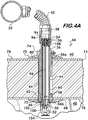
- FIG. 4A shows another embodiment 66 of a sprinkler assembly according to the invention having a first sleeve 56a positioned proximate to the first end 38 of the conduit 36 and a second sleeve 56b positioned proximate to the second end 46 of the conduit.
- the sleeves may be formed of insulating material such as natural rubber, EPDM, Buna N, PTFE, silicone, cork or other similar materials.
- each sleeve 56a and 56b may have an inwardly facing surface 58 which contacts the outwardly facing surface 60 of the conduit, and an outwardly facing surface 62 which contacts an inwardly facing surface 64 of the substrate 14 within the opening 44.
- Outwardly facing surfaces 62 of sleeves 56a and 56b may be tapered, and the sleeves cooperate to support the sprinkler assembly on the substrate.
- escutcheons 68 and 70 Additional support for the sprinkler assembly 66 is provided by a pair of escutcheons 68 and 70 positioned surrounding the opening 44 on opposite sides of the substrate 14.
- escutcheon 68 is positioned proximate to the second end 46 of the conduit 36 and is retained to the assembly by engagement with the sprinkler 50.
- a portion 72 of second sleeve 56b extends from the opening 44 and is engaged by the escutcheon 68.
- Escutcheon 70 is positioned proximate to the first end 38 of conduit 36 and is mounted on the conduit.
- the escutcheon 70 is retained to the conduit by a clamp 74, which may be integral with the escutcheon or, as shown, a separate component.
- first sleeve 56a extends from opening 44 and is engaged by the escutcheon 70.
- FIG. 5 Another sprinkler assembly embodiment 82 is illustrated in Figure 5 wherein the escutcheon 70 is secured to the conduit 36 threadedly by compatible screw threads 84 and 86 respectively positioned on the escutcheon and the conduit. Rotation of the escutcheon 70 when in contact with the substrate surface 78 draws the escutcheon 68 into contact with the opposite surface 76 and thereby supports the sprinkler assembly 82 on the substrate and between the escutcheons. Note that the escutcheon 68 is shown in phantom line, which indicates that it may be attached to the assembly in one of a number of ways.
- Figure 6 shows escutcheon 68 attached to the conduit 36 by a clamp 88
- Figure 7 shows the escutcheon 68 threadedly attached to the conduit 36 by means of compatible screw threads 90 and 92 respectively on the escutcheon and the conduit 36.
- the second end 46 of the conduit extends from the opening 44 beyond the surface 76 of the substrate.
- Escutcheon 70 is shown in phantom line in Figures 6 and 7 indicating that it could be mounted on the conduit 36 in any one of a number of ways which provide support to the assembly.
- Figure 8 shows a sprinkler assembly embodiment which uses plates 85, 87 in contact with the substrate surfaces 76 and 78, respectively, to help distribute loads imposed by the sprinkler assembly onto the substrate 14.
- the plate 85 is captured between the surface and an escutcheon 68 mounted on the sprinkler 50.
- Plate 87, engaging opposite surface 78, is held in place against the surface by a hex nut 89 threaded to the conduit 36.
- Nut 89 acts as a compression nut to secure the sprinkler assembly to the substrate upon tightening.
- valve 54 positioned, in this example, within the conduit 36, is in its closed configuration which maintains the conduit 36 in a dry condition by keeping water or other fire suppressing fluid in the flexible hose 42 and the piping network 22.
- a valve closing member 94 is held in sealing engagement with a seat 96 positioned within the conduit 36 proximate to the first end 38 of the conduit 36 by a rod 98.
- Rod 98 extends from the valve closing member 94 through the conduit 36 to a cap 100 which covers the opening 102 of sprinkler 50.
- Cap 100 is held in position by the heat sensitive trigger 52, which is supported by the sprinkler arms 104.
- Heat sensitive trigger 52 may be, for example, a frangible glass bulb filled with a heat sensitive liquid, or a mechanism held together by a solder having a precisely defined melting temperature.
- Rod 98, and therefore the closing member 94 to which it is attached, are biased into the open configuration by a spring element 106 which acts between the seat 96 and a stabilizing spider 108 attached to the rod 98.
- a spring element 106 which acts between the seat 96 and a stabilizing spider 108 attached to the rod 98.
- Rod 98 now unconstrained, moves toward the sprinkler 50 under the biasing force of spring 106 as well as the water pressure against the valve closing member 94 and thus allows the valve closing member to unseat and thereby permit water 110 to flow through the conduit 36 to be discharged from the sprinkler 50 onto the fire.
- Sprinkler assemblies according to the invention permit greater flexibility in the design and construction of fire suppression systems by supporting the sprinkler assembly within the substrates forming the structure being protected, and not rigidly from the piping network.
Landscapes
- Health & Medical Sciences (AREA)
- Public Health (AREA)
- Business, Economics & Management (AREA)
- Emergency Management (AREA)
- Engineering & Computer Science (AREA)
- Operations Research (AREA)
- Fire-Extinguishing By Fire Departments, And Fire-Extinguishing Equipment And Control Thereof (AREA)
- Nozzles (AREA)
Description
- This invention concerns sprinkler systems and installations at the interface between environments having large temperature differences.
- Sprinkler systems for fire suppression are used to protect structures which separate or enclose adjacent regions having large temperature differences from one another. Examples of such structures include freezers, balconies of apartments, and loading docks of warehouses. Each of these structures has one or more walls and/or ceilings which separate a region wherein the temperature is maintained above the freezing point of water from a region where the temperature is maintained below freezing or can drop below freezing.
- It is a challenge to provide fire protection to such structures, especially when water is the preferred fire suppressing liquid because measures must be taken to ensure that the water does not freeze within the piping network or the sprinklers. To meet this challenge it is known to position the piping network in the temperature controlled "warm" environment where water within the pipes will not freeze, and to provide "dry" type sprinkler assemblies which extend from the piping network through openings in the ceiling or walls of the structure and into the "cold" or uncontrolled environment. An example of such a dry type sprinkler assembly is disclosed in
US5967240 . Such dry sprinkler assemblies have elongated conduits extending between the sprinkler and the piping network with a valve inside to maintain the sprinkler assembly in a "dry" state, i.e., without water, until the sprinkler is activated by the heat from a fire. A heat sensitive trigger, for example a liquid filled frangible bulb, which breaks when subjected to heat from a fire, opens the sprinkler to permit discharge of the water and also acts to open the valve and allow water to flow from the piping network through the conduit and out through the sprinkler. - In prior art sprinkler systems the dry sprinkler assemblies are rigidly connected to the piping network and therefore do not require supplemental support when they extend through the wall or ceiling of the structure into the cold or uncontrolled environment. However, this rigid design is unforgiving with respect to the relative positioning of the openings and the dry sprinkler assemblies, requiring precise alignment between assembly and opening during construction and installation.
WO2006/058330 solves this problem by providing some spacing between the supply conduit and the inwardly facing surface within the opening in the wall of the cold environment and with flexible sealing devices on both sides of the wall. It would be advantageous to permit more flexibility between the dry sprinkler assembly and the piping network so that a greater variation between opening and sprinkler assembly position could be tolerated, thereby simplifying the design and construction of such systems. - The invention concerns a sprinkler assembly connectable in fluid communication with a piping network carrying a fire suppressing liquid. The sprinkler assembly is extendable through an opening in a substrate. The sprinkler assembly comprises a conduit having a first end connectable to the piping network on one side of the substrate and a second end positionable adjacent to an opposite side of the substrate. A valve associated with the assembly is movable between a closed position to prevent the liquid from entering the conduit, and an open position to allow the liquid to flow through the conduit. In one embodiment the valve is positioned within the conduit. A sprinkler is mounted on the second end of the conduit. A sleeve is positioned within the opening and surrounding the conduit.
- In one embodiment, the sleeve is positioned proximate to the first end of the conduit. A portion of the sleeve may extend from the opening. The assembly further comprises an escutcheon positioned on the one side of the substrate and surrounding the opening. The escutcheon may engage the portion of the sleeve extending from the opening.
- The assembly may further comprise an escutcheon positioned on the one side of the substrate and surrounding the opening, wherein the escutcheon is mounted on the conduit, for example by screw threads.
- Alternately a clamp may engage the conduit and be positioned adjacent to the escutcheon.
- A sleeve may also be positioned proximate to the second end of the conduit. A portion of the sleeve may extend from the opening. In this embodiment the assembly may further comprise an escutcheon positioned on the opposite side of the substrate and surrounding the opening, the escutcheon engaging the portion of the sleeve. The escutcheon may mounted on the conduit, for example by screw threads, or a clamp may engage the conduit for attaching the escutcheon to it. Alternately, the escutcheon may be mounted on the sprinkler.
- The sleeves may have an inwardly facing surface in contact with an outwardly facing surface of the conduit, and an outwardly facing surface in contact with an inwardly facing surface of the substrate within the opening. Preferably the outwardly facing surface of the sleeves are tapered. The assembly may further comprise a flexible hose attached to the first end of the conduit for connecting the conduit to the piping network.
- In another embodiment of a sprinkler assembly connectable in fluid communication with a piping network carrying a fire suppressing liquid, the sprinkler assembly being extendable through an opening in a substrate, the sprinkler assembly comprises a conduit having a first end connectable to the piping network on one side of the substrate and a second end positionable adjacent to an opposite side of the substrate. A valve associated with the assembly is movable between a closed position to prevent the liquid from entering the conduit, and an open position to allow the liquid to flow through the conduit. In one embodiment the valve is positioned within the conduit. A sprinkler is mounted on the second end of the conduit. A first sleeve is positioned within the opening and surrounding the conduit. The first sleeve is positioned proximate to the first end of the conduit. A second sleeve is positioned within the opening and surrounding the conduit. The second sleeve is positioned proximate to the second end of the conduit.
- The invention further encompasses a freezer, comprising a compartment defined by a plurality of interconnected substrates. A piping network is positioned outside of the compartment and supplies a fire suppressing liquid. The freezer includes at least one sprinkler assembly comprising a conduit extending through an opening in one of the substrates. The conduit has a first end connected to the piping network on one side of the one substrate and a second end positioned adjacent to an opposite side of the one substrate. A valve associated with the assembly is movable between a closed position to prevent the liquid from entering the conduit, and an open position to allow the liquid to flow through the conduit. In one embodiment the valve is positioned within the conduit. A sprinkler is mounted on the second end of the conduit and a sleeve is positioned within the opening and surrounding the conduit.
- In an alternate embodiment the freezer comprises a compartment defined by a plurality of interconnected substrates. A piping network is positioned outside of the compartment and supplies a fire suppressing liquid. The sprinkler includes at least one sprinkler assembly comprising a conduit extending through an opening in one of the substrates. The conduit has a first end connected to the piping network on one side of the one substrate and a second end positioned adjacent to an opposite side of the one substrate. A valve associated with the assembly is movable between a closed position to prevent the liquid from entering the conduit, and an open position to allow the liquid to flow through the conduit. In one embodiment the valve is positioned within the conduit. A sprinkler is mounted on the second end of the conduit. A first sleeve is positioned within the opening and surrounding the conduit, the first sleeve being positioned proximate to the first end of the conduit. A second sleeve is positioned within the opening and surrounding the conduit, the second sleeve being positioned proximate to the second end of the conduit.
- The invention also includes a sprinkler installation, comprising a structure comprising a temperature controlled interior space and an exterior space separated from one another by a substrate. A piping network is positioned within the temperature controlled interior space and supplies a fire suppressing liquid. The installation includes at least one sprinkler assembly comprising a conduit extending through an opening in the substrate. The conduit has a first end connected to the piping network and a second end positioned adjacent to the exterior space. A valve associated with the assembly is movable between a closed position to prevent the liquid from entering the conduit, and an open position to allow the liquid to flow through the conduit. In one embodiment the valve is positioned within the conduit. A sprinkler is mounted on the second end of the conduit and extends into the exterior space. A first sleeve is positioned within the opening and surrounding the conduit. The first sleeve is positioned proximate to the first end of the conduit. A second sleeve is positioned within the opening and surrounding the conduit. The second sleeve is positioned proximate to the second end of the conduit.
-
-
Figure 1 is a partial cut-away isometric view of a freezer sprinkler installation according to the invention; -
Figure 2 is a partial sectional elevational view of a sprinkler installation according to the invention; -
Figure 3 is a sectional view of an example embodiment of a sprinkler assembly according to the invention; -
Figures 4A and4B are sectional views of another example embodiment of a sprinkler assembly according to the invention; and -
Figures 5 through 8 are sectional views of example embodiments of sprinkler assemblies according to the invention. -
Figure 1 shows asprinkler assembly 10 installed in afreezer 12 for fire protection.Freezer 12 comprises a plurality ofsubstrates 14, in this example forming walls 16 and ceiling 18 interconnected to define acompartment 20. Apiping network 22 is positioned outside of the compartment and supplies a fire suppressing liquid, for example, water, to the sprinkler assembly. Thefreezer 12 may be located within a building, such as a climate controlled warehouse, wherein the ambient temperature is maintained so that water or other fire suppressing liquid in thepiping network 22 does not freeze. -
Figure 2 shows another example sprinkler installation, in this embodiment, aloading dock 26 of awarehouse 28. Thewarehouse 28 comprises a temperature controlledinterior space 30 defined by a substrate 32 (the exterior wall of the warehouse). Thepiping network 22 is positioned within the interior space, and theloading dock 26 comprises an exterior space (not temperature controlled) which receivestrucks 34 for pick-up and delivery of goods. The local exterior space of the loading dock is protected by thesprinkler assembly 10 according to the invention. It is understood that other similar installations are also feasible, for example a balcony of an apartment, comprising an exterior space where temperature control is not practical, is protected by a sprinkler assembly partially housed in a neighboring interior space (the apartment) which is climate controlled. -
Figure 3 shows in detail an example embodiment of thesprinkler assembly 10 according to the invention.Assembly 10 comprises aconduit 36 having afirst end 38 connectable to thepiping network 22 on oneside 40 of thesubstrate 14. Connection to the piping network is advantageously effected by aflexible hose 42, which could be, for example, a corrugated metal hose or a hose comprising a braided outer sleeve surrounding a flexible inner tubular member.Conduit 36 extends through anopening 44 in thesubstrate 14 and has asecond end 46 positioned adjacent to anopposite side 48 of thesubstrate 14. Thesecond end 46 ofconduit 36 may extend proud of the substrate as shown, or it may be flush with or beneath the surface of theopposite side 48. Asprinkler 50 is mounted on thesecond end 46 of theconduit 36. The sprinkler has a heatsensitive trigger 52 which operates to open the assembly and allow water or other fire suppressing liquid to flow from thepiping network 22 to the sprinkler for discharge onto a fire. Because thesecond end 46 ofconduit 36 is exposed to a cold environment, for example within a freezer compartment, or on the outside of a building, the conduit is normally maintained in a dry state, i.e., without water, to prevent freezing within the conduit. Avalve 54, an example of which is described in detail below, may be positioned within theconduit 36, and keeps the water within the flexible hose 42 (and within the temperature controlled warm environment) until a fire causes the heat sensitive trigger to open the sprinkler, which also opens thevalve 54 and thereby allow water to flow through theconduit 36 to thesprinkler 50. - It is advantageous to support the
sprinkler assembly 10 within the substrate, as it has significant weight which may not be properly supported from thepiping network 22 by theflexible hose 42. To that end asleeve 56 is positioned within theopening 44 surrounding theconduit 36.Sleeve 56 may be formed of an insulating material such as natural rubber, EPDM, Buna N, PTFE, silicone, cork or other similar materials. Thesleeve 56 has an inwardly facingsurface 58 that is in contact with an outwardly facingsurface 60 of theconduit 36. The sleeve also has an outwardly facingsurface 62 which contacts an inwardly facingsurface 64 within theopening 44 of thesubstrate 14. Friction between the various surfaces supports the conduit, and thus thesprinkler assembly 10 in thesubstrate 14. Outwardly facingsurface 62 ofsleeve 56 may be tapered as shown to facilitate insertion of the sleeve into theopening 44.Sleeve 56 may be longer or shorter than the example shown, as required for effective support of the sprinkler assembly, and may also be positioned anywhere along the length of theconduit 36 within theopening 44. -
Figure 4A shows anotherembodiment 66 of a sprinkler assembly according to the invention having afirst sleeve 56a positioned proximate to thefirst end 38 of theconduit 36 and asecond sleeve 56b positioned proximate to thesecond end 46 of the conduit. Again, the sleeves may be formed of insulating material such as natural rubber, EPDM, Buna N, PTFE, silicone, cork or other similar materials. As described above, eachsleeve surface 58 which contacts the outwardly facingsurface 60 of the conduit, and an outwardly facingsurface 62 which contacts an inwardly facingsurface 64 of thesubstrate 14 within theopening 44. Outwardly facingsurfaces 62 ofsleeves - Additional support for the
sprinkler assembly 66 is provided by a pair ofescutcheons opening 44 on opposite sides of thesubstrate 14. In this example,escutcheon 68 is positioned proximate to thesecond end 46 of theconduit 36 and is retained to the assembly by engagement with thesprinkler 50. Note that aportion 72 ofsecond sleeve 56b extends from theopening 44 and is engaged by theescutcheon 68.Escutcheon 70 is positioned proximate to thefirst end 38 ofconduit 36 and is mounted on the conduit. In the example shown inFigure 4A , theescutcheon 70 is retained to the conduit by aclamp 74, which may be integral with the escutcheon or, as shown, a separate component. Tightening of theclamp 74 cinches it to the conduit and thereby fixes theescutcheons respective surfaces opposite sides substrate 14 to provide support to theassembly 66. Aportion 80 offirst sleeve 56a extends from opening 44 and is engaged by theescutcheon 70. - Another sprinkler assembly embodiment 82 is illustrated in
Figure 5 wherein theescutcheon 70 is secured to theconduit 36 threadedly by compatible screw threads 84 and 86 respectively positioned on the escutcheon and the conduit. Rotation of theescutcheon 70 when in contact with thesubstrate surface 78 draws theescutcheon 68 into contact with theopposite surface 76 and thereby supports the sprinkler assembly 82 on the substrate and between the escutcheons. Note that theescutcheon 68 is shown in phantom line, which indicates that it may be attached to the assembly in one of a number of ways. For example,Figure 6 showsescutcheon 68 attached to theconduit 36 by aclamp 88, whereasFigure 7 shows theescutcheon 68 threadedly attached to theconduit 36 by means of compatible screw threads 90 and 92 respectively on the escutcheon and theconduit 36. Note that in the example embodiments shown inFigures 6 and7 thesecond end 46 of the conduit extends from theopening 44 beyond thesurface 76 of the substrate.Escutcheon 70 is shown in phantom line inFigures 6 and7 indicating that it could be mounted on theconduit 36 in any one of a number of ways which provide support to the assembly. -
Figure 8 shows a sprinkler assembly embodiment which usesplates substrate 14. As shown engagingsurface 76, theplate 85 is captured between the surface and anescutcheon 68 mounted on thesprinkler 50.Plate 87, engaging oppositesurface 78, is held in place against the surface by ahex nut 89 threaded to theconduit 36.Nut 89 acts as a compression nut to secure the sprinkler assembly to the substrate upon tightening. - Operation of an example sprinkler assembly applicable to any of the feasible installations is described with reference to
Figures 4A and4B . As shown inFigure 4A , thevalve 54, positioned, in this example, within theconduit 36, is in its closed configuration which maintains theconduit 36 in a dry condition by keeping water or other fire suppressing fluid in theflexible hose 42 and thepiping network 22. In the closed configuration, avalve closing member 94 is held in sealing engagement with aseat 96 positioned within theconduit 36 proximate to thefirst end 38 of theconduit 36 by arod 98.Rod 98 extends from thevalve closing member 94 through theconduit 36 to acap 100 which covers theopening 102 ofsprinkler 50.Cap 100 is held in position by the heatsensitive trigger 52, which is supported by thesprinkler arms 104. Heatsensitive trigger 52 may be, for example, a frangible glass bulb filled with a heat sensitive liquid, or a mechanism held together by a solder having a precisely defined melting temperature.Rod 98, and therefore the closingmember 94 to which it is attached, are biased into the open configuration by aspring element 106 which acts between theseat 96 and a stabilizingspider 108 attached to therod 98. As shown inFigure 4B , when the heat from a fire causes thetrigger 52 to break or fall apart it no longer supports thecap 100, which is subjected to the compression force ofspring 106 and water pressure acting onvalve closing member 94 through the action ofrod 98.Cap 100, not being fixedly attached to any part of the sprinkler assembly, falls away and releases therod 98.Rod 98, now unconstrained, moves toward thesprinkler 50 under the biasing force ofspring 106 as well as the water pressure against thevalve closing member 94 and thus allows the valve closing member to unseat and thereby permitwater 110 to flow through theconduit 36 to be discharged from thesprinkler 50 onto the fire. - Sprinkler assemblies according to the invention permit greater flexibility in the design and construction of fire suppression systems by supporting the sprinkler assembly within the substrates forming the structure being protected, and not rigidly from the piping network.
Claims (20)
- A sprinkler assembly (10, 66) connectable in fluid communication with a piping network (22) carrying a fire suppressing liquid, said sprinkler assembly (10, 66) being extendable through an opening (44) in a substrate (14,32), said sprinkler assembly (10, 66) comprising:a conduit (36) having a first end connectable to said piping network (22) on one side (40) of said substrate (14,32) and a second end (46) positionable adjacent to an opposite side (48) of said substrate (14,32);a valve (54) movable between a closed position preventing said liquid from entering said conduit (36), and an open position allowing said liquid to flow through said conduit (36);a sprinkler (50) mounted on said second end (46) of said conduit (36); characterized bya sleeve (56) positioned within said opening (44) and surrounding said conduit (36);wherein in use of the sprinkler assembly (10) the conduit (36) is supported in the substrate (14,32) by friction between an inwardly facing surface (58) of the sleeve (56) in contact with an outwardly facing surface (60) of the conduit (36) and between an outwardly facing surface (62) of the sleeve (56) and an inwardly facing surface (64) within the opening (44) of the substrate (14,32).
- The sprinkler assembly (10, 66) of claim 1, wherein a first sleeve (56a) being positioned proximate to said first end (38) of said conduit (36); a second sleeve (56b) positioned within said opening (44) and surrounding said conduit (36), said second sleeve (56b) being positioned proximate to said second end (46) of said conduit (36).
- The sprinkler assembly (10, 66) according to Claim 1 or 2, wherein said valve (54) is positioned within said conduit (36).
- The sprinkler assembly (10, 66) according to Claim 1, wherein said sleeve (56) is positioned proximate to said first end (38) of said conduit (36); preferably
a portion of said sleeve (56) extends from said opening (44), said assembly further comprising an escutcheon (68, 70) positioned on said one side (40) of said substrate (14) and surrounding said opening (44), said escutcheon (68, 70) engaging said portion of said sleeve (56). - The sprinkler assembly (10, 66) according to Claim 1, wherein said sleeve (56) is positioned proximate to said first end (38) of said conduit (36), and
comprising an escutcheon (68, 70) positioned on said one side (40) of said substrate (14) and surrounding said opening (44), said escutcheon (68, 70) being mounted on said conduit (36). - The sprinkler assembly (10, 66) according to Claim 5, wherein said escutcheon (68, 70) is threadedly attached to said conduit (36); or
said sprinkler assembly (10, 66) further comprises a clamp engaging said conduit (36) and positioned adjacent to said escutcheon (68, 70). - The sprinkler assembly (10, 66) according to Claim 1, wherein said sleeve (56) is positioned proximate to said second end (46) of said conduit (36); preferably
a portion of said sleeve (56) extends from said opening (44), said assembly further comprising an escutcheon (68, 70) positioned on said opposite side (48) of said substrate (14) and surrounding said opening (44), said escutcheon (68, 70) engaging said portion of said sleeve (56); or
said sprinkler assembly (10, 66) further comprises an escutcheon (68, 70) positioned on said opposite side (48) of said substrate (14) and surrounding said opening (44), said escutcheon (68, 70) being mounted on said sprinkler (50). - The sprinkler assembly (10, 66) according to Claim 1 or 2, wherein said sleeve (56) is positioned proximate to said second end (46) of said conduit (36); and
an escutcheon (68, 70) is positioned on said opposite side (48) of said substrate (14) and surrounding said opening (44), said escutcheon (68, 70) being mounted on said conduit (36). - The sprinkler assembly according to claim 8, wherein said escutcheon (68, 70) is threadedly attached to said conduit (36); or
said sprinkler assembly (10, 66) further comprises a clamp (74) engaging said conduit (36) for attaching said escutcheon (68, 70) thereto. - The sprinkler assembly (10, 66) according to Claim 1, wherein said sleeve (56) has an inwardly facing surface (58) in contact with an outwardly facing surface (60) of said conduit (36), said sleeve (56) further having an outwardly facing surface (62) in contact with an inwardly facing surface (64) of said substrate (14,32) within said opening (44).
- The sprinkler assembly according to claim 10, wherein said outwardly facing surface (62) of said sleeve (56) is tapered.
- The sprinkler assembly (10, 66) according to Claim 1, further comprising a flexible hose (42) attached to said first end of said conduit (36) for connecting said conduit (36) to said piping network (22).
- The sprinkler assembly (10, 66) according to Claim 2, wherein said first or second sleeve (56a, 56b) has an inwardly facing surface (58) in contact with an outwardly facing surface (60) of said conduit (36), said first sleeve (56a) or respectfully second sleeve (56b) further having an outwardly facing surface (62) in contact with an inwardly facing surface (64) of said substrate (14,32) within said opening (44).
- The sprinkler assembly (10, 66) according to Claim 2, further comprising a first and an optional second escutcheon (68, 70) positioned on said one side (40) and respectively on said opposite side (48) of said substrate (14,32), said first escutcheon (68) and said respective second escutcheon (70) surrounding said opening (44).
- The sprinkler assembly (10, 66) according to Claim 2, further comprising a first escutcheon (68) positioned on said one side (40) of said substrate (14,32), said first escutcheon (68) surrounding said opening (44); wherein
a portion of said first sleeve (56a) extends from said opening (44), said first escutcheon (68) engaging said portion of said first sleeve (56a); or
said first escutcheon (68) is mounted on said conduit (36). - The sprinkler assembly (10, 66) according to Claim 2, further comprising a first escutcheon (68) positioned on said one side of said substrate (14,32), said first escutcheon (68) surrounding said opening (44); preferably
a second escutcheon (70) positioned on said opposite side (48) of said substrate (14), said second escutcheon (70) surrounding said opening (44); wherein
a portion of said second sleeve (56b) extends from said opening (44), said second escutcheon (70) engaging said portion of said second sleeve (56b); or
said second escutcheon (70) is mounted on said conduit (36); or
said second escutcheon (70) is mounted on said sprinkler (50). - A freezer, comprising: a compartment (20) defined by a plurality of interconnected substrates (14); a piping network (22) positioned outside of said compartment (20) and supplying a fire suppressing liquid; at least one sprinkler assembly (10, 66) according to claims 1, 3-5, 7, 8, 9 and 12.
- A freezer, comprising: a compartment (20) defined by a plurality of interconnected substrates (14); a piping network (22) positioned outside of said compartment (20) and supplying a fire suppressing liquid; at least one sprinkler assembly (10, 66) according to claims 2, 3, and 12-16.
- A sprinkler installation (10, 66), comprising: a structure comprising a temperature controlled interior space (30) and an exterior space (26) separated from one another by a substrate (32); a piping network (22) positioned within said temperature controlled interior space (30) and supplying a fire suppressing liquid; at least one sprinkler assembly (10, 66); a conduit (36) extending through an opening in said substrate (32), said conduit (36) having a first end (38) connected to said piping network (22) and a second end (46) positioned adjacent to said exterior space (26); a sprinkler (50) mounted on said second end(46) of said conduit (36) and extending into said exterior space (26) according to claims 2, 3 and 10-16.
- The sprinkler installation (10, 66) according to Claim 19, wherein said first sleeve (56a) has an inwardly facing surface (58) in contact with an outwardly facing surface (60) of said conduit (36), said first sleeve (56a) further having an outwardly facing surface (62) in contact with an inwardly facing surface (64) of said substrate (32) within said opening (44) wherein said outwardly facing surface (62) of said first or second sleeve (56b) is tapered.
Applications Claiming Priority (2)
| Application Number | Priority Date | Filing Date | Title |
|---|---|---|---|
| US13/206,969 US9511248B2 (en) | 2011-08-10 | 2011-08-10 | Sprinkler system and installation |
| PCT/US2012/044147 WO2013022523A1 (en) | 2011-08-10 | 2012-06-26 | Sprinkler system and installation |
Publications (3)
| Publication Number | Publication Date |
|---|---|
| EP2741829A1 EP2741829A1 (en) | 2014-06-18 |
| EP2741829A4 EP2741829A4 (en) | 2015-04-15 |
| EP2741829B1 true EP2741829B1 (en) | 2016-12-28 |
Family
ID=47668779
Family Applications (1)
| Application Number | Title | Priority Date | Filing Date |
|---|---|---|---|
| EP12822047.2A Active EP2741829B1 (en) | 2011-08-10 | 2012-06-26 | Sprinkler system and installation |
Country Status (11)
| Country | Link |
|---|---|
| US (1) | US9511248B2 (en) |
| EP (1) | EP2741829B1 (en) |
| JP (2) | JP6033305B2 (en) |
| KR (1) | KR101966662B1 (en) |
| CN (1) | CN103764232B (en) |
| AU (1) | AU2012294921B2 (en) |
| BR (1) | BR112014003020A2 (en) |
| CA (1) | CA2837466C (en) |
| ES (1) | ES2619705T3 (en) |
| MX (1) | MX346154B (en) |
| WO (1) | WO2013022523A1 (en) |
Families Citing this family (16)
| Publication number | Priority date | Publication date | Assignee | Title |
|---|---|---|---|---|
| US10449402B2 (en) * | 2012-12-20 | 2019-10-22 | Victaulic Company | Dry sprinkler |
| EP2996814A4 (en) * | 2013-05-13 | 2016-10-26 | Cold spray nozzle assembly | |
| US10646736B2 (en) | 2015-07-28 | 2020-05-12 | Victaulic Company | Preaction sprinkler valve assemblies, related dry sprinkler devices adapted for long travel, and fire protection sprinkler systems |
| WO2017019904A1 (en) | 2015-07-28 | 2017-02-02 | Globe Fire Sprinkler Corporation | Preaction sprinkler valve assemblies, related dry sprinkler devices and fire protection sprinkler systems |
| WO2017083810A1 (en) * | 2015-11-11 | 2017-05-18 | The Reliable Automatic Sprinkler Co. | Dry sprinkler |
| US20170165511A1 (en) * | 2015-12-15 | 2017-06-15 | Globe Fire Sprinkler Corporation | Fire protection systems and methods for attic/combustible concealed spaces beneath pitched roofs using preaction sprinkler valve assemblies and related dry sprinkler devices |
| US10279367B2 (en) | 2016-10-11 | 2019-05-07 | Anvil International, Llc | Sprinkler assembly connector for flexible conduit |
| US10850144B2 (en) | 2017-06-14 | 2020-12-01 | Victaulic Company | Preaction sprinkler valve assemblies, related dry sprinkler devices, and compressive activation mechanism |
| US11045675B2 (en) | 2018-02-02 | 2021-06-29 | Victaulic Company | Belleville seal for valve seat having a tear drop laminar flow feature |
| CN109759251A (en) * | 2019-03-12 | 2019-05-17 | 九牧厨卫股份有限公司 | A kind of clamping separation assembly and shower |
| JP7438539B2 (en) | 2020-07-03 | 2024-02-27 | 轟産業株式会社 | Sealed cover body for extinguishing agent discharge head |
| CN116018185A (en) * | 2020-09-02 | 2023-04-25 | 泰科消防产品有限合伙公司 | Electronic Dry Sprinkler Assembly |
| WO2022192158A1 (en) * | 2021-03-08 | 2022-09-15 | Tyco Fire Products Lp | Systems and methods for sprinkler systems with flexible hose and rapid seal adapter |
| KR20250171397A (en) * | 2021-04-06 | 2025-12-08 | 빅톨릭 컴패니 | Fitting and Gasket |
| US12496479B2 (en) * | 2021-04-07 | 2025-12-16 | Tyco Fire Products Lp | Fire protection sprinkler assembly |
| CN116206811B (en) * | 2022-09-09 | 2025-04-15 | 安徽瑞之星电子科技集团有限公司 | Fireproof cable and its components |
Family Cites Families (50)
| Publication number | Priority date | Publication date | Assignee | Title |
|---|---|---|---|---|
| US3125358A (en) | 1964-03-17 | Building lead-in connection for a pipe | ||
| US1903150A (en) * | 1932-04-04 | 1933-03-28 | Tyden Emil | Pendant sprinkler system |
| US3031212A (en) | 1957-12-06 | 1962-04-24 | Boeing Co | Pipe to wall connection having injection type securing and sealing means |
| FR1428317A (en) | 1964-03-09 | 1966-02-11 | Wilhelm Kopp | Shell for pipe insulation |
| GB1159606A (en) | 1966-09-30 | 1969-07-30 | Anton Jensen & Co As | Pipe-Sleeve Devices |
| GB1249113A (en) | 1967-11-06 | 1971-10-06 | Richard Klinger Ltd | Improvements in seals and bearings for shafts |
| US3584689A (en) | 1969-06-26 | 1971-06-15 | Norris Industries | Dry-type sprinkler |
| US4071265A (en) * | 1975-09-24 | 1978-01-31 | Wallace Thomas J | Threaded mechanical joint wall sleeve |
| GB1564662A (en) | 1977-06-15 | 1980-04-10 | Mather & Platt Ltd | Sprinkler arrangements |
| US4165105A (en) | 1977-12-27 | 1979-08-21 | General Electric Company | Cabinet transition sleeve |
| US4385777A (en) | 1980-06-02 | 1983-05-31 | The Logsdon Foundation | Decorative escutcheon capable of inhibiting the propagation of noise |
| JPS5779555U (en) * | 1980-10-31 | 1982-05-17 | ||
| JPS5779555A (en) | 1980-11-05 | 1982-05-18 | Fujitsu Ltd | Advanced control system for instruction |
| US4417626A (en) * | 1982-07-12 | 1983-11-29 | Interfit, Inc. | Adjustable pendent sprinkler assembly |
| JPS63130076A (en) | 1986-11-20 | 1988-06-02 | ニツタン株式会社 | Unwinding piping of sprinkler fire extinguishing apparatus and installation thereof |
| US4918761A (en) * | 1988-06-02 | 1990-04-24 | Harbeke Gerold J | Method of using a toilet-flange cast-in mount |
| US5228520A (en) | 1988-12-22 | 1993-07-20 | Holger Gottschalk | Sprinkler system for refrigerated spaces |
| CN2044882U (en) | 1989-04-05 | 1989-09-27 | 成都市解放仪表厂 | Temp. sensitive sprinkling valve |
| US5188185A (en) | 1991-06-19 | 1993-02-23 | Grinnell Corporation | Dry sprinkler |
| DE4122665A1 (en) | 1991-07-09 | 1993-01-14 | Total Feuerschutz Gmbh | SPRINKLER FOR AUTOMATIC FIRE-FIGHTING SYSTEMS |
| US5390465A (en) * | 1993-03-11 | 1995-02-21 | The Lamson & Sessions Co. | Passthrough device with firestop |
| US5775431A (en) * | 1996-09-11 | 1998-07-07 | The Reliable Automatic Sprinkler Co., Inc. | Dry sprinkler arrangements |
| JP2000153908A (en) | 1998-11-20 | 2000-06-06 | Murata Mach Ltd | Rack for automated storage and retrieval system |
| US6488097B1 (en) * | 1999-01-08 | 2002-12-03 | Pnm, Inc. | Fire protection sprinkler head support |
| DE19913483A1 (en) | 1999-03-25 | 2000-09-28 | Goedecke Ag | Process for the preparation of heterocyclic carbamates from aza heterocycles and carbon dioxide |
| US6367560B1 (en) | 1999-04-30 | 2002-04-09 | Factory Mutual Research Corp. | Wet sprinkler system for cold environments |
| US6752217B2 (en) | 2000-03-16 | 2004-06-22 | Victaulic Company Of America | Dry accelerator for sprinkler system |
| US6293348B1 (en) | 2000-03-27 | 2001-09-25 | Victaulic Fire Safety Company, L.L.C. | Low pressure actuator for dry sprinkler system |
| US6708771B2 (en) | 2000-03-27 | 2004-03-23 | Victaulic Company Of America | Low pressure electro-pneumatic and gate actuator |
| US6666277B2 (en) | 2000-03-27 | 2003-12-23 | Victaulic Company Of America | Low pressure pneumatic and gate actuator |
| US6536533B2 (en) | 2000-03-27 | 2003-03-25 | Victaulic Company Of America | Low pressure actuator for dry sprinkler system |
| FI112038B (en) | 2000-05-16 | 2003-10-31 | Marioff Corp Oy | Mounting device for mounting a spray head on a wall |
| US6851482B2 (en) | 2000-11-02 | 2005-02-08 | Kevin Michael Dolan | Sprinkler assembly |
| US6715561B2 (en) | 2001-06-29 | 2004-04-06 | Viking Corporation | Vacuum dry sprinkler system containing a sprinkler head with expulsion assembly |
| US20030075343A1 (en) | 2001-10-22 | 2003-04-24 | National Foam, Inc., D/B/A Kidde Fire Fighting | Dry sprinkler |
| DE20117370U1 (en) | 2001-10-26 | 2002-02-14 | Minimax Gmbh, 23843 Bad Oldesloe | Sprinklerbefestigungselement |
| US7143834B2 (en) | 2001-11-01 | 2006-12-05 | Kevin Michael Dolan | Sprinkler assembly |
| US7516800B1 (en) | 2002-07-19 | 2009-04-14 | Tyco Fire Products Lp | Dry sprinkler |
| US6907938B2 (en) | 2002-08-07 | 2005-06-21 | Pbj, Llc | Decorative support panel |
| US7389824B2 (en) | 2003-09-05 | 2008-06-24 | The Viking Corporation | Fire extinguishing system |
| CA2635434C (en) | 2003-09-05 | 2012-02-07 | The Viking Corporation | Preaction fire extinguishing system for esfr cold storage applications |
| CA2462636C (en) | 2004-02-09 | 2010-09-14 | The Viking Corporation | Dry sprinkler assembly |
| AU2004100686A4 (en) | 2004-08-20 | 2004-09-23 | Hales And Lunn Pty Ltd | Insulated fire sprinkler extension |
| CN2732281Y (en) | 2004-10-09 | 2005-10-12 | 石成雄 | Fire side wall sprinkler quick response structure |
| US7213319B2 (en) | 2004-11-29 | 2007-05-08 | Tyco Fire Products Lp | Method of installing a dry sprinkler installation |
| US7559376B2 (en) | 2004-12-01 | 2009-07-14 | Tyco Fire Products Lp | Dry sprinkler with a diverter seal assembly |
| US7766252B2 (en) | 2006-02-15 | 2010-08-03 | The Viking Corporation | Dry sprinkler assembly |
| US7373720B1 (en) | 2006-03-20 | 2008-05-20 | Jensen Raymond H | Fire sprinkler flexible piping system, bracing apparatus therefor, and method of installing a fire sprinkler |
| US7921928B2 (en) * | 2008-08-18 | 2011-04-12 | The Viking Corporation | 90 degree dry horizontal sidewall sprinkler |
| AR078273A1 (en) | 2009-09-11 | 2011-10-26 | Victaulic Co Of America | FLEXIBLE SPRAYER ASSY |
-
2011
- 2011-08-10 US US13/206,969 patent/US9511248B2/en active Active
-
2012
- 2012-06-26 AU AU2012294921A patent/AU2012294921B2/en not_active Ceased
- 2012-06-26 ES ES12822047.2T patent/ES2619705T3/en active Active
- 2012-06-26 BR BR112014003020A patent/BR112014003020A2/en not_active Application Discontinuation
- 2012-06-26 KR KR1020137031767A patent/KR101966662B1/en not_active Expired - Fee Related
- 2012-06-26 MX MX2014001578A patent/MX346154B/en active IP Right Grant
- 2012-06-26 CA CA2837466A patent/CA2837466C/en active Active
- 2012-06-26 WO PCT/US2012/044147 patent/WO2013022523A1/en not_active Ceased
- 2012-06-26 CN CN201280037585.3A patent/CN103764232B/en not_active Expired - Fee Related
- 2012-06-26 JP JP2014525014A patent/JP6033305B2/en not_active Expired - Fee Related
- 2012-06-26 EP EP12822047.2A patent/EP2741829B1/en active Active
-
2016
- 2016-05-23 JP JP2016102115A patent/JP2016147129A/en not_active Withdrawn
Non-Patent Citations (1)
| Title |
|---|
| None * |
Also Published As
| Publication number | Publication date |
|---|---|
| JP2016147129A (en) | 2016-08-18 |
| US20130037281A1 (en) | 2013-02-14 |
| JP2014525277A (en) | 2014-09-29 |
| EP2741829A1 (en) | 2014-06-18 |
| CN103764232A (en) | 2014-04-30 |
| MX2014001578A (en) | 2014-02-27 |
| WO2013022523A1 (en) | 2013-02-14 |
| AU2012294921B2 (en) | 2016-12-01 |
| EP2741829A4 (en) | 2015-04-15 |
| KR101966662B1 (en) | 2019-04-09 |
| CN103764232B (en) | 2016-10-19 |
| ES2619705T3 (en) | 2017-06-26 |
| US9511248B2 (en) | 2016-12-06 |
| KR20140058429A (en) | 2014-05-14 |
| CA2837466A1 (en) | 2013-02-14 |
| CA2837466C (en) | 2020-03-24 |
| BR112014003020A2 (en) | 2017-02-21 |
| MX346154B (en) | 2017-03-08 |
| AU2012294921A1 (en) | 2013-11-28 |
| JP6033305B2 (en) | 2016-11-30 |
| HK1195526A1 (en) | 2014-11-14 |
Similar Documents
| Publication | Publication Date | Title |
|---|---|---|
| US9511248B2 (en) | Sprinkler system and installation | |
| US11730990B2 (en) | Flexible dry sprinkler having a differential pressure controller | |
| AU2022201645B2 (en) | Dry sprinkler assembly | |
| CA2588852A1 (en) | Dry sprinkler installation and sealing device | |
| HK1195526B (en) | Sprinkler system and installation | |
| GB2449131A (en) | Fire sprinkler assembly | |
| US20160144213A1 (en) | Automatic Fire Suppressing System | |
| HK40051943A (en) | Dry sprinkler assembly | |
| HK40051943B (en) | Dry sprinkler assembly | |
| HK1187847A (en) | Flexible dry sprinklers |
Legal Events
| Date | Code | Title | Description |
|---|---|---|---|
| PUAI | Public reference made under article 153(3) epc to a published international application that has entered the european phase |
Free format text: ORIGINAL CODE: 0009012 |
|
| 17P | Request for examination filed |
Effective date: 20140304 |
|
| AK | Designated contracting states |
Kind code of ref document: A1 Designated state(s): AL AT BE BG CH CY CZ DE DK EE ES FI FR GB GR HR HU IE IS IT LI LT LU LV MC MK MT NL NO PL PT RO RS SE SI SK SM TR |
|
| DAX | Request for extension of the european patent (deleted) | ||
| REG | Reference to a national code |
Ref country code: DE Ref legal event code: R079 Ref document number: 602012027192 Country of ref document: DE Free format text: PREVIOUS MAIN CLASS: A62C0037110000 Ipc: A62C0003000000 |
|
| RA4 | Supplementary search report drawn up and despatched (corrected) |
Effective date: 20150317 |
|
| RIC1 | Information provided on ipc code assigned before grant |
Ipc: A62C 35/62 20060101ALI20150311BHEP Ipc: A62C 37/11 20060101ALI20150311BHEP Ipc: F16L 59/12 20060101ALI20150311BHEP Ipc: A62C 3/00 20060101AFI20150311BHEP Ipc: A62C 35/68 20060101ALI20150311BHEP |
|
| 17Q | First examination report despatched |
Effective date: 20151106 |
|
| GRAP | Despatch of communication of intention to grant a patent |
Free format text: ORIGINAL CODE: EPIDOSNIGR1 |
|
| INTG | Intention to grant announced |
Effective date: 20160613 |
|
| GRAJ | Information related to disapproval of communication of intention to grant by the applicant or resumption of examination proceedings by the epo deleted |
Free format text: ORIGINAL CODE: EPIDOSDIGR1 |
|
| GRAJ | Information related to disapproval of communication of intention to grant by the applicant or resumption of examination proceedings by the epo deleted |
Free format text: ORIGINAL CODE: EPIDOSDIGR1 |
|
| GRAP | Despatch of communication of intention to grant a patent |
Free format text: ORIGINAL CODE: EPIDOSNIGR1 |
|
| GRAS | Grant fee paid |
Free format text: ORIGINAL CODE: EPIDOSNIGR3 |
|
| INTC | Intention to grant announced (deleted) | ||
| INTG | Intention to grant announced |
Effective date: 20161010 |
|
| GRAA | (expected) grant |
Free format text: ORIGINAL CODE: 0009210 |
|
| AK | Designated contracting states |
Kind code of ref document: B1 Designated state(s): AL AT BE BG CH CY CZ DE DK EE ES FI FR GB GR HR HU IE IS IT LI LT LU LV MC MK MT NL NO PL PT RO RS SE SI SK SM TR |
|
| REG | Reference to a national code |
Ref country code: GB Ref legal event code: FG4D |
|
| REG | Reference to a national code |
Ref country code: CH Ref legal event code: EP |
|
| REG | Reference to a national code |
Ref country code: AT Ref legal event code: REF Ref document number: 856798 Country of ref document: AT Kind code of ref document: T Effective date: 20170115 |
|
| REG | Reference to a national code |
Ref country code: IE Ref legal event code: FG4D |
|
| REG | Reference to a national code |
Ref country code: DE Ref legal event code: R096 Ref document number: 602012027192 Country of ref document: DE |
|
| PG25 | Lapsed in a contracting state [announced via postgrant information from national office to epo] |
Ref country code: LV Free format text: LAPSE BECAUSE OF FAILURE TO SUBMIT A TRANSLATION OF THE DESCRIPTION OR TO PAY THE FEE WITHIN THE PRESCRIBED TIME-LIMIT Effective date: 20161228 |
|
| REG | Reference to a national code |
Ref country code: LT Ref legal event code: MG4D |
|
| PG25 | Lapsed in a contracting state [announced via postgrant information from national office to epo] |
Ref country code: GR Free format text: LAPSE BECAUSE OF FAILURE TO SUBMIT A TRANSLATION OF THE DESCRIPTION OR TO PAY THE FEE WITHIN THE PRESCRIBED TIME-LIMIT Effective date: 20170329 Ref country code: LT Free format text: LAPSE BECAUSE OF FAILURE TO SUBMIT A TRANSLATION OF THE DESCRIPTION OR TO PAY THE FEE WITHIN THE PRESCRIBED TIME-LIMIT Effective date: 20161228 Ref country code: SE Free format text: LAPSE BECAUSE OF FAILURE TO SUBMIT A TRANSLATION OF THE DESCRIPTION OR TO PAY THE FEE WITHIN THE PRESCRIBED TIME-LIMIT Effective date: 20161228 |
|
| REG | Reference to a national code |
Ref country code: NL Ref legal event code: MP Effective date: 20161228 |
|
| REG | Reference to a national code |
Ref country code: AT Ref legal event code: MK05 Ref document number: 856798 Country of ref document: AT Kind code of ref document: T Effective date: 20161228 |
|
| REG | Reference to a national code |
Ref country code: NO Ref legal event code: T2 Effective date: 20161228 |
|
| REG | Reference to a national code |
Ref country code: FR Ref legal event code: PLFP Year of fee payment: 6 |
|
| PG25 | Lapsed in a contracting state [announced via postgrant information from national office to epo] |
Ref country code: FI Free format text: LAPSE BECAUSE OF FAILURE TO SUBMIT A TRANSLATION OF THE DESCRIPTION OR TO PAY THE FEE WITHIN THE PRESCRIBED TIME-LIMIT Effective date: 20161228 Ref country code: HR Free format text: LAPSE BECAUSE OF FAILURE TO SUBMIT A TRANSLATION OF THE DESCRIPTION OR TO PAY THE FEE WITHIN THE PRESCRIBED TIME-LIMIT Effective date: 20161228 Ref country code: RS Free format text: LAPSE BECAUSE OF FAILURE TO SUBMIT A TRANSLATION OF THE DESCRIPTION OR TO PAY THE FEE WITHIN THE PRESCRIBED TIME-LIMIT Effective date: 20161228 |
|
| REG | Reference to a national code |
Ref country code: ES Ref legal event code: FG2A Ref document number: 2619705 Country of ref document: ES Kind code of ref document: T3 Effective date: 20170626 |
|
| PG25 | Lapsed in a contracting state [announced via postgrant information from national office to epo] |
Ref country code: NL Free format text: LAPSE BECAUSE OF FAILURE TO SUBMIT A TRANSLATION OF THE DESCRIPTION OR TO PAY THE FEE WITHIN THE PRESCRIBED TIME-LIMIT Effective date: 20161228 |
|
| PG25 | Lapsed in a contracting state [announced via postgrant information from national office to epo] |
Ref country code: SK Free format text: LAPSE BECAUSE OF FAILURE TO SUBMIT A TRANSLATION OF THE DESCRIPTION OR TO PAY THE FEE WITHIN THE PRESCRIBED TIME-LIMIT Effective date: 20161228 Ref country code: IS Free format text: LAPSE BECAUSE OF FAILURE TO SUBMIT A TRANSLATION OF THE DESCRIPTION OR TO PAY THE FEE WITHIN THE PRESCRIBED TIME-LIMIT Effective date: 20170428 Ref country code: RO Free format text: LAPSE BECAUSE OF FAILURE TO SUBMIT A TRANSLATION OF THE DESCRIPTION OR TO PAY THE FEE WITHIN THE PRESCRIBED TIME-LIMIT Effective date: 20161228 Ref country code: CZ Free format text: LAPSE BECAUSE OF FAILURE TO SUBMIT A TRANSLATION OF THE DESCRIPTION OR TO PAY THE FEE WITHIN THE PRESCRIBED TIME-LIMIT Effective date: 20161228 Ref country code: EE Free format text: LAPSE BECAUSE OF FAILURE TO SUBMIT A TRANSLATION OF THE DESCRIPTION OR TO PAY THE FEE WITHIN THE PRESCRIBED TIME-LIMIT Effective date: 20161228 |
|
| PG25 | Lapsed in a contracting state [announced via postgrant information from national office to epo] |
Ref country code: AT Free format text: LAPSE BECAUSE OF FAILURE TO SUBMIT A TRANSLATION OF THE DESCRIPTION OR TO PAY THE FEE WITHIN THE PRESCRIBED TIME-LIMIT Effective date: 20161228 Ref country code: PL Free format text: LAPSE BECAUSE OF FAILURE TO SUBMIT A TRANSLATION OF THE DESCRIPTION OR TO PAY THE FEE WITHIN THE PRESCRIBED TIME-LIMIT Effective date: 20161228 Ref country code: SM Free format text: LAPSE BECAUSE OF FAILURE TO SUBMIT A TRANSLATION OF THE DESCRIPTION OR TO PAY THE FEE WITHIN THE PRESCRIBED TIME-LIMIT Effective date: 20161228 Ref country code: PT Free format text: LAPSE BECAUSE OF FAILURE TO SUBMIT A TRANSLATION OF THE DESCRIPTION OR TO PAY THE FEE WITHIN THE PRESCRIBED TIME-LIMIT Effective date: 20170428 Ref country code: BG Free format text: LAPSE BECAUSE OF FAILURE TO SUBMIT A TRANSLATION OF THE DESCRIPTION OR TO PAY THE FEE WITHIN THE PRESCRIBED TIME-LIMIT Effective date: 20170328 |
|
| REG | Reference to a national code |
Ref country code: DE Ref legal event code: R097 Ref document number: 602012027192 Country of ref document: DE |
|
| PLBE | No opposition filed within time limit |
Free format text: ORIGINAL CODE: 0009261 |
|
| STAA | Information on the status of an ep patent application or granted ep patent |
Free format text: STATUS: NO OPPOSITION FILED WITHIN TIME LIMIT |
|
| PG25 | Lapsed in a contracting state [announced via postgrant information from national office to epo] |
Ref country code: DK Free format text: LAPSE BECAUSE OF FAILURE TO SUBMIT A TRANSLATION OF THE DESCRIPTION OR TO PAY THE FEE WITHIN THE PRESCRIBED TIME-LIMIT Effective date: 20161228 |
|
| 26N | No opposition filed |
Effective date: 20170929 |
|
| PG25 | Lapsed in a contracting state [announced via postgrant information from national office to epo] |
Ref country code: MC Free format text: LAPSE BECAUSE OF FAILURE TO SUBMIT A TRANSLATION OF THE DESCRIPTION OR TO PAY THE FEE WITHIN THE PRESCRIBED TIME-LIMIT Effective date: 20161228 |
|
| REG | Reference to a national code |
Ref country code: CH Ref legal event code: PL |
|
| PG25 | Lapsed in a contracting state [announced via postgrant information from national office to epo] |
Ref country code: SI Free format text: LAPSE BECAUSE OF FAILURE TO SUBMIT A TRANSLATION OF THE DESCRIPTION OR TO PAY THE FEE WITHIN THE PRESCRIBED TIME-LIMIT Effective date: 20161228 |
|
| REG | Reference to a national code |
Ref country code: IE Ref legal event code: MM4A |
|
| PG25 | Lapsed in a contracting state [announced via postgrant information from national office to epo] |
Ref country code: CH Free format text: LAPSE BECAUSE OF NON-PAYMENT OF DUE FEES Effective date: 20170630 Ref country code: LU Free format text: LAPSE BECAUSE OF NON-PAYMENT OF DUE FEES Effective date: 20170626 Ref country code: IE Free format text: LAPSE BECAUSE OF NON-PAYMENT OF DUE FEES Effective date: 20170626 Ref country code: LI Free format text: LAPSE BECAUSE OF NON-PAYMENT OF DUE FEES Effective date: 20170630 |
|
| REG | Reference to a national code |
Ref country code: FR Ref legal event code: PLFP Year of fee payment: 7 |
|
| PG25 | Lapsed in a contracting state [announced via postgrant information from national office to epo] |
Ref country code: MT Free format text: LAPSE BECAUSE OF NON-PAYMENT OF DUE FEES Effective date: 20170626 |
|
| PG25 | Lapsed in a contracting state [announced via postgrant information from national office to epo] |
Ref country code: HU Free format text: LAPSE BECAUSE OF FAILURE TO SUBMIT A TRANSLATION OF THE DESCRIPTION OR TO PAY THE FEE WITHIN THE PRESCRIBED TIME-LIMIT; INVALID AB INITIO Effective date: 20120626 |
|
| PG25 | Lapsed in a contracting state [announced via postgrant information from national office to epo] |
Ref country code: CY Free format text: LAPSE BECAUSE OF NON-PAYMENT OF DUE FEES Effective date: 20161228 |
|
| PG25 | Lapsed in a contracting state [announced via postgrant information from national office to epo] |
Ref country code: MK Free format text: LAPSE BECAUSE OF FAILURE TO SUBMIT A TRANSLATION OF THE DESCRIPTION OR TO PAY THE FEE WITHIN THE PRESCRIBED TIME-LIMIT Effective date: 20161228 |
|
| REG | Reference to a national code |
Ref country code: DE Ref legal event code: R082 Ref document number: 602012027192 Country of ref document: DE Representative=s name: MEISSNER BOLTE PATENTANWAELTE RECHTSANWAELTE P, DE |
|
| PG25 | Lapsed in a contracting state [announced via postgrant information from national office to epo] |
Ref country code: AL Free format text: LAPSE BECAUSE OF FAILURE TO SUBMIT A TRANSLATION OF THE DESCRIPTION OR TO PAY THE FEE WITHIN THE PRESCRIBED TIME-LIMIT Effective date: 20161228 |
|
| PGFP | Annual fee paid to national office [announced via postgrant information from national office to epo] |
Ref country code: FR Payment date: 20200520 Year of fee payment: 9 Ref country code: TR Payment date: 20200617 Year of fee payment: 9 Ref country code: NO Payment date: 20200527 Year of fee payment: 9 |
|
| PGFP | Annual fee paid to national office [announced via postgrant information from national office to epo] |
Ref country code: BE Payment date: 20200520 Year of fee payment: 9 Ref country code: IT Payment date: 20200611 Year of fee payment: 9 |
|
| PGFP | Annual fee paid to national office [announced via postgrant information from national office to epo] |
Ref country code: ES Payment date: 20200701 Year of fee payment: 9 |
|
| REG | Reference to a national code |
Ref country code: NO Ref legal event code: MMEP |
|
| REG | Reference to a national code |
Ref country code: BE Ref legal event code: MM Effective date: 20210630 |
|
| PG25 | Lapsed in a contracting state [announced via postgrant information from national office to epo] |
Ref country code: NO Free format text: LAPSE BECAUSE OF NON-PAYMENT OF DUE FEES Effective date: 20210630 Ref country code: FR Free format text: LAPSE BECAUSE OF NON-PAYMENT OF DUE FEES Effective date: 20210630 |
|
| PG25 | Lapsed in a contracting state [announced via postgrant information from national office to epo] |
Ref country code: IT Free format text: LAPSE BECAUSE OF NON-PAYMENT OF DUE FEES Effective date: 20210626 Ref country code: BE Free format text: LAPSE BECAUSE OF NON-PAYMENT OF DUE FEES Effective date: 20210630 |
|
| PGFP | Annual fee paid to national office [announced via postgrant information from national office to epo] |
Ref country code: GB Payment date: 20220526 Year of fee payment: 11 Ref country code: DE Payment date: 20220512 Year of fee payment: 11 |
|
| REG | Reference to a national code |
Ref country code: ES Ref legal event code: FD2A Effective date: 20220902 |
|
| PG25 | Lapsed in a contracting state [announced via postgrant information from national office to epo] |
Ref country code: ES Free format text: LAPSE BECAUSE OF NON-PAYMENT OF DUE FEES Effective date: 20210627 |
|
| REG | Reference to a national code |
Ref country code: DE Ref legal event code: R119 Ref document number: 602012027192 Country of ref document: DE |
|
| GBPC | Gb: european patent ceased through non-payment of renewal fee |
Effective date: 20230626 |
|
| PG25 | Lapsed in a contracting state [announced via postgrant information from national office to epo] |
Ref country code: DE Free format text: LAPSE BECAUSE OF NON-PAYMENT OF DUE FEES Effective date: 20240103 Ref country code: GB Free format text: LAPSE BECAUSE OF NON-PAYMENT OF DUE FEES Effective date: 20230626 |