EP2741719B1 - Ostomy appliance - Google Patents
Ostomy appliance Download PDFInfo
- Publication number
- EP2741719B1 EP2741719B1 EP12822013.4A EP12822013A EP2741719B1 EP 2741719 B1 EP2741719 B1 EP 2741719B1 EP 12822013 A EP12822013 A EP 12822013A EP 2741719 B1 EP2741719 B1 EP 2741719B1
- Authority
- EP
- European Patent Office
- Prior art keywords
- inlet
- pouch
- output tap
- ostomy appliance
- sealing surface
- Prior art date
- Legal status (The legal status is an assumption and is not a legal conclusion. Google has not performed a legal analysis and makes no representation as to the accuracy of the status listed.)
- Active
Links
Images

Classifications
-
- A—HUMAN NECESSITIES
- A61—MEDICAL OR VETERINARY SCIENCE; HYGIENE
- A61F—FILTERS IMPLANTABLE INTO BLOOD VESSELS; PROSTHESES; DEVICES PROVIDING PATENCY TO, OR PREVENTING COLLAPSING OF, TUBULAR STRUCTURES OF THE BODY, e.g. STENTS; ORTHOPAEDIC, NURSING OR CONTRACEPTIVE DEVICES; FOMENTATION; TREATMENT OR PROTECTION OF EYES OR EARS; BANDAGES, DRESSINGS OR ABSORBENT PADS; FIRST-AID KITS
- A61F5/00—Orthopaedic methods or devices for non-surgical treatment of bones or joints; Nursing devices ; Anti-rape devices
- A61F5/44—Devices worn by the patient for reception of urine, faeces, catamenial or other discharge; Colostomy devices
- A61F5/445—Colostomy, ileostomy or urethrostomy devices
-
- A—HUMAN NECESSITIES
- A61—MEDICAL OR VETERINARY SCIENCE; HYGIENE
- A61F—FILTERS IMPLANTABLE INTO BLOOD VESSELS; PROSTHESES; DEVICES PROVIDING PATENCY TO, OR PREVENTING COLLAPSING OF, TUBULAR STRUCTURES OF THE BODY, e.g. STENTS; ORTHOPAEDIC, NURSING OR CONTRACEPTIVE DEVICES; FOMENTATION; TREATMENT OR PROTECTION OF EYES OR EARS; BANDAGES, DRESSINGS OR ABSORBENT PADS; FIRST-AID KITS
- A61F5/00—Orthopaedic methods or devices for non-surgical treatment of bones or joints; Nursing devices ; Anti-rape devices
- A61F5/44—Devices worn by the patient for reception of urine, faeces, catamenial or other discharge; Colostomy devices
- A61F5/4404—Details or parts
-
- A—HUMAN NECESSITIES
- A61—MEDICAL OR VETERINARY SCIENCE; HYGIENE
- A61F—FILTERS IMPLANTABLE INTO BLOOD VESSELS; PROSTHESES; DEVICES PROVIDING PATENCY TO, OR PREVENTING COLLAPSING OF, TUBULAR STRUCTURES OF THE BODY, e.g. STENTS; ORTHOPAEDIC, NURSING OR CONTRACEPTIVE DEVICES; FOMENTATION; TREATMENT OR PROTECTION OF EYES OR EARS; BANDAGES, DRESSINGS OR ABSORBENT PADS; FIRST-AID KITS
- A61F5/00—Orthopaedic methods or devices for non-surgical treatment of bones or joints; Nursing devices ; Anti-rape devices
- A61F5/44—Devices worn by the patient for reception of urine, faeces, catamenial or other discharge; Colostomy devices
- A61F5/4404—Details or parts
- A61F5/4405—Valves or valve arrangements specially adapted therefor ; Fluid inlets or outlets
-
- A—HUMAN NECESSITIES
- A61—MEDICAL OR VETERINARY SCIENCE; HYGIENE
- A61F—FILTERS IMPLANTABLE INTO BLOOD VESSELS; PROSTHESES; DEVICES PROVIDING PATENCY TO, OR PREVENTING COLLAPSING OF, TUBULAR STRUCTURES OF THE BODY, e.g. STENTS; ORTHOPAEDIC, NURSING OR CONTRACEPTIVE DEVICES; FOMENTATION; TREATMENT OR PROTECTION OF EYES OR EARS; BANDAGES, DRESSINGS OR ABSORBENT PADS; FIRST-AID KITS
- A61F5/00—Orthopaedic methods or devices for non-surgical treatment of bones or joints; Nursing devices ; Anti-rape devices
- A61F5/44—Devices worn by the patient for reception of urine, faeces, catamenial or other discharge; Colostomy devices
- A61F5/4404—Details or parts
- A61F5/4407—Closure means other than valves
-
- A—HUMAN NECESSITIES
- A61—MEDICAL OR VETERINARY SCIENCE; HYGIENE
- A61F—FILTERS IMPLANTABLE INTO BLOOD VESSELS; PROSTHESES; DEVICES PROVIDING PATENCY TO, OR PREVENTING COLLAPSING OF, TUBULAR STRUCTURES OF THE BODY, e.g. STENTS; ORTHOPAEDIC, NURSING OR CONTRACEPTIVE DEVICES; FOMENTATION; TREATMENT OR PROTECTION OF EYES OR EARS; BANDAGES, DRESSINGS OR ABSORBENT PADS; FIRST-AID KITS
- A61F5/00—Orthopaedic methods or devices for non-surgical treatment of bones or joints; Nursing devices ; Anti-rape devices
- A61F5/44—Devices worn by the patient for reception of urine, faeces, catamenial or other discharge; Colostomy devices
- A61F5/441—Devices worn by the patient for reception of urine, faeces, catamenial or other discharge; Colostomy devices having venting or deodorant means, e.g. filters ; having antiseptic means, e.g. bacterial barriers
Definitions
- the present disclosure relates to ostomy appliances of the kind disclosed in claim 1.
- Ostomy pouches for the collection of body waste output from a stoma are well known. Ostomy pouches typically include flat, opposing side walls secured together along their edges to define a human stomal discharge collection cavity. One of the side walls is provided with an opening to receive a stoma, and means such as a connecting flange is provided for securing the pouch to an adhesive barrier placed to surround the stoma so that body waste discharged through the stoma will be received within the cavity.
- the ostomy pouch may have a discharge opening which may be closed during collection of body waste that passes through the stoma but may be opened for draining the body waste from the pouch after a period of use.
- the ostomy pouch may be designed for a single use in which case it will not be provided with a discharge opening since the entire pouch will be discarded after it has substantially filled with human stomal discharge.
- a drainable ostomy pouch comprising a first or proximal and a second or distal side wall of flexible sheet material sealed to each other for defining a cavity therebetween for receiving human stomal discharge through an aperture in the proximal side wall and an elongate drainage portion extending downwardly in a longitudinal direction and ending in a drainage opening extending transversely to the longitudinal direction, a first or proximal and a second or distal flexible stiffening strip extending immediately adjacent to and along said drainage opening and are attached for instance by heat sealing or adhesion to the outer surface of the first and second side walls, respectively, of said drainage portion.
- a drainable pouch is typically reusable following periodic emptying of the body waste by utilizing a closure for the discharge opening.
- Such closures may take a number of different forms so long as it serves to prevent leakage of the body waste.
- Some drainable pouches are designed to be coupled to drainage tubes leading to relatively large volume bedside containers. These permit stoma discharge to drain continuously through the pouch into the container so that, for example, the user can sleep through the night without periodic need to empty the contents of the ostomy pouch.
- Such drainable pouches include an output tap for connecting to a drainage tube, either directly or via an adapter. Output taps typically have a generally cylindrical shape and a circular cross-sectional area. They are bulky under clothing and can have difficulty passing large pieces of solid matters. This can often lead to user discomfort and clogged night time drainage systems.
- such an ostomy appliance can separate solid matter from liquid waste. More desirably, such an appliance includes an outlet that can discharge liquid waste separate from or in conjunction with solid waste from the ostomy pouch.
- Drainable ostomy pouches which can connect to an external container for continuous drainage of pouch contents have been used for ostomy patients.
- ileostomy patients have used high output drainable ostomy pouches, which include an output tap for draining stoma discharge, which is typically a mixture of liquids and solids.
- Output taps for high output drainable pouches typically have a generally cylindrical shape with a circular cross-sectional area, and are formed of a polymeric material that maintains a cylindrical lumen.
- these output taps are bulky under clothing and often become clogged when attached to a night drain collector. This can cause leakage and disrupt a user's sleep.
- the ostomy appliance includes an ostomy pouch configured to separate solids and liquids in stoma discharge and allow separated liquids to continuously drain while keeping solids in the pouch to reduce the risk of the output tap becoming clogged.
- solids are retained in a body side chamber and liquids flow into an outer chamber of the ostomy pouch.
- the ostomy appliance can include a liquid valve or tap on the outer chamber for connecting to a night drainage container to drain liquids from the outer chamber.
- the ostomy pouch also includes an outlet, which can be opened to drain all outputs, such as a drainable fold-up type closure.
- the ostomy appliance includes a high output tap that has a generally flat profile, which lays flat against the user.
- a high output tap is less bulky than conventional high output taps and provides a higher degree of discretion for the user.
- the output tap of the present invention includes a lumen, the size of which can be increased to accommodate larger solids, thereby reducing a risk of clogging.
- the output tap includes a closure cap that may fit both inside and outside of a tap outlet to provide a secure, two-location seal when the closure cap is engaged with the tap.
- a flat high output tap is configured to connect to a night drainage tube directly or via an adapter to drain liquids from the ostomy pouch. The same flat high output tap can be opened to empty both liquids and solids in the ostomy pouch.
- the present invention relates to an ostomy appliance as claimed in claim 1.
- an ostomy appliance in an example (not falling under the scope of the present invention) includes a pouch, which includes a first chamber and a second chamber, an inlet, at least one outlet, and a filter configured to separate liquids and solids in body waste received via the inlet.
- an ostomy appliance in another example (not falling under the scope of the present invention) includes a pouch, which includes a first chamber and a second chamber, a pouch inlet, a pouch outlet, and a flat output tap.
- the flat output tap is attached to the pouch outlet, and includes at least one inlet, an outlet, and a lumen providing a path for the body waste to flow out of the pouch.
- the flat output tap is configured such that a size of the lumen is adjustable.
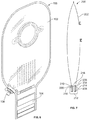
- the ostomy appliance 10 includes an ostomy pouch 12 and a flat output tap 14.
- the ostomy pouch 12 is a dual-chamber pouch including a body side chamber 16 and an outer chamber 18.
- the ostomy pouch 12 includes flat, opposing side walls, namely a body side wall 20 and an outer wall 22, and a center wall 24, which includes a separating or filtering section 26.
- the opposing side walls 20, 22, and the center wall 24 are secured together along their edges 28, for example via heat sealing, to define the body side chamber 16 and the outer chamber 18.
- the body side wall 20 is provided with an inlet opening 30 to receive a stoma, and a pouch side connecting flange 32 for securing the ostomy pouch 10 to an adhesive barrier (not shown) placed around the stoma via a body side connecting flange (not shown) so that body waste material discharged through the stoma is received within the body side chamber 16 of the ostomy pouch 12.
- this embodiment is shown as a two-piece ostomy appliance including the pouch side connecting flange 32 and the separate adhesive barrier including the body side connecting flange (not shown), in other embodiments, the ostomy appliance may be a one piece pouch, wherein an adhesive skin barrier is directly attached to the pouch.
- the filtering section 20 is configured to separate liquids from solids in body waste entering the body side chamber 16 via the inlet opening 30.
- the filtering section 20 includes a plurality of openings, for example, a plurality of perforations or slits, to allow liquids to pass through the filtering section into the outer chamber 18, but block solids from passing through the filtering section 20.
- the filtering section 20 includes plurality of circular openings, each opening may have a diameter between about 1 mm and about 5 mm, for example, between about 2 mm and about 4 mm.
- the filtering section may have different shape and/or size openings to accommodate different body wastes to effectively separate liquids from solids.
- the size of the openings may be smaller than 1 mm diameter.
- the ostomy appliance 10 includes a tail portion 33.
- the flat output tap 14 is arranged in the tail portion 33 and is sealingly attached to inner surfaces of the peripheral end of the tail portion 33.
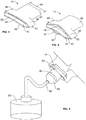
- a perspective view of the flat output tap 14 is shown in FIG. 3 .
- the flat output tap 14 is a one-piece tap formed of a flexible, resilient material via a conventional molding process.
- Su Caribbean materials for the flat output tap 14 include, but not limited to, silicone, rubber, elastomers and the like.
- the flat output tap 14 has a generally flat profile, and includes a lumen 48 defining an outlet path for stoma discharge to exit the ostomy pouch 12.
- the term "generally flat profile" is used herein to describe a shape of the output tap that has a width:thickness ratio of at least 2, wherein the width 64 ( FIG. 3 ) and the thickness 66 ( FIG. 2 ) are measured at the outlet end of the output tap, such that the output tap lays flat when the ostomy appliance is worn by the user to provide the user with a greater degree of discretion when compared to conventional output taps having circular cross-sectional areas.
- the flat output tap 14 has a top portion 44, which is configured to fit in the peripheral end of the tail portion 33 of the ostomy pouch 12, and a bottom portion 46 defining a discharge outlet 34.
- the bottom portion 46 has a flattened cylinder-like shape, such that in a relaxed state, the width 64 ( FIG. 3 ) is greater than the thickness 66 ( FIG. 2 ). In the illustrated embodiment, the width 64 to thickness 66 ratio of the bottom portion 46 is greater than 2, and preferably greater than 4.
- the top portion 44 may include three sealing surfaces 38, 40, 42 for sealing against the pouch walls 22, 24, 20.
- a first sealing surface 38 and a second sealing surface 40 are formed on one side of the flat output tap 14, and a third sealing surface 42 is formed on the opposite side of the output tap 14.
- the top portion 44 includes a first lip 50 and a second lip 51.
- the second sealing surface 40 is formed on the first lip 50, and the third sealing surface 42 is formed on the second lip 51.
- the lips 50, 51 are in contact with each other in a closed lip position as shown in FIGS. 2-3 , until pressure is applied along edges 52 of the top portion 44 to open the lips 50, 51, as shown in FIGS. 1 , 3, and 4 .
- the user can press edges 52 with his fingers to open the lips 50, 51.
- FIG. 4 shows the flat output tap 14 in an open position.
- the lips 50, 51 define an inlet from the body side chamber 16, which remains closed until pressure is applied to open the inlet.
- An opening 54 arranged between the first sealing surface 38 and the second sealing surface 40 defines a liquid inlet from the outer chamber 18.
- the flat output tap 14 is arranged in the tail portion 33 of the ostomy pouch 12 such that the first sealing surface 38 faces an inner surface of the outer wall 22, the second sealing surface 40 faces a body side surface of the center wall 24, and the third sealing surface 42 faces an inner surface of the body side wall 20.
- the first sealing surface 38 is sealingly attached to the inner surface of the outer wall 22.
- the second sealing surface 40 is sealingly attached to the surface of the center wall 24, which faces the body side chamber 16.
- the third sealing surface 42 is sealingly attached to the inner surface of the body side wall 20.
- the sealing surfaces 38, 40, 42 can be attached to the walls 22, 24, 20 using conventional methods, such as heat sealing or adhesives.
- the ostomy appliance 10 can include a closure cap 36 ( FIG. 1 ), which may fit both inside and outside of an outlet end portion 35 of the flat output tap 14, to provide a wo-location, leak free seal when the closure cap 36 is engaged with the flat output tap 14.
- the closure cap 36 may be tethered to the flat output tap 14.
- the ostomy appliance 10 which is sealingly closed with the closure cap 36, is attached to the adhesive skin barrier (not shown.)
- Stoma discharge flows in via the opening 30 into the body side chamber 16.
- the stoma discharge typically includes both liquids and solids.
- the liquids in the stoma discharge flows into the outer chamber 18 from the body side chamber 16 through the center wall filtering section 26.
- the stoma discharge is generally separated into liquids and solids via the filtering section 26.
- an adapter 58 is engaged with the discharge outlet 34 for draining body waste in the ostomy pouch 12 to a collection container 60 via tube 62.
- an outlet 56 of the body side chamber 16 is closed by the closed lips 50, 51 of the flat output tap 14, which prevents solids in the body side chamber 16 from flowing through the discharge outlet 34.
- An outlet 57 of the outer chamber 18 is in fluid communication with the discharge outlet 34 via the opening 54 in the flat output tap 14.
- the liquids in the outer chamber 18 flow out through the discharge outlet 34, through the adapter 58, and into the collection container 60 via tube 62.
- only liquids, which are separated from solids via the filtering section 26, are continuously drained into the collection container 60.
- risk of the flat output tap 14, the adapter 58, and/or the tube 62 becoming clogged by solids is significantly reduced or eliminated.
- the flat output tap 14 can be pressed inwardly at edges 52, as shown in FIGS. 3 and 4 , which opens the lip 50, which in turn opens the outlet 56 of the body side chamber 16 to empty the solids.
- the opening 54 may remain open, so both liquids and solids can be drained via the discharge outlet 34 of the flat output tap 14.
- the bottom portion 46 can also be pressed on its edges to increase the size of the lumen 48 to improve draining of solids and liquids.
- FIG. 6 illustrates an ostomy appliance 100 according to an alternative embodiment. Similar to ostomy appliance 10, ostomy appliance 100 includes a dual-chamber ostomy pouch 102, which includes a body side chamber for solids and an outer chamber for liquids. However, instead of the flat output tap, ostomy appliance 100 includes a fold-up type closure 104 and a liquid valve 106. Examples of such a fold-up type closures are disclosed in Villefrance, et al., US Patent No. 7,879,015 , and Mandzij, et al., US Patent No. 7,879,016 .
- the chambers of the ostomy pouch 102 are defined by a body side wall, a center wall with a filtering section, and an outer wall.
- the fold-up type closure 104 is rolled up and closed, outlets of the body side chamber and the outer chamber are closed, and the chambers are separated by the center wall.
- solids and liquids in stoma discharge flowing into the body side chamber are generally separated as described above with regard to ostomy appliance 10.
- the outer chamber of the ostomy pouch 100 is provided with the liquid valve 106, through which the liquids in the outer chamber can be drained into a collection container (not shown.)
- the fold-up type closure 104 can be opened or unrolled, which opens outlets of the body side chamber and the outer chamber, and both liquids and solids can be emptied together.
- FIG. 7 illustrates an ostomy appliance 200 according to another embodiment.
- the ostomy appliance 200 includes an ostomy pouch 202 and a flat output tap 204.
- the ostomy pouch 202 may be any two-piece or one-piece conventional single chambered ostomy pouch.
- the flat output tap 204 has a generally flat profile.
- the flat output tap 204 includes a top portion 206, which is adapted to fit in a tail portion 210 of the ostomy pouch 202, and a bottom portion 208 having a flattened cylinder-like shape.
- the bottom portion 208 has a width 222 to thickness 224 ratio of greater 2, and preferably greater than 4.
- the flat output tap 204 is formed of a flexible, resilient material, such as silicone, rubber, elastomers, and the like.
- Ostomy appliance 200 also includes a closure cap 212, which may be adapted to fit both inside and outside of an outlet end portion 210 of the flat output tap 204 to provide a two-location, leak-free seal when the closure cap 212 is engaged with the flat output tap 204.
- the closure cap 212 includes an outer wall 214 and a protruding insertion portion 216 arranged in the center of the outer wall 214. When the cap 212 is engaged with the tap, the insertion portion 216 is inserted into a lumen 220 of the flat output tap 204, such that the bottom portion 208 of the flat output tap 204 is positioned in a cavity 218 defined between the outer wall 214 and the insertion portion 216 of the closure cap 212.
- the closure cap 212 fits both inside and outside of the bottom portion 208 to provide the two-location, leak free seal.
- the closure cap 212 may be tethered to the flat output tap 204.
- the flat output tap 204 includes the lumen 220, which is generally flat and has a relatively small cross-sectional thickness. Thus, flow of discharge through the lumen may be restricted.
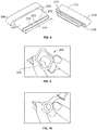
- the flat output tap 204 is configured such that the flow of discharge can be manually controlled by increasing the size of the lumen 220. As shown in FIG. 9 , the flat output tap 204 can be pressed on its sides to increase the flow area of the lumen 220. By controlling the amount of the pressure applied, the size of the lumen 220 can be controlled.
- FIG. 9 shows the lumen 220 fully opened to allow maximum flow of stoma discharge.
- a tube or adapter (not shown) can be connected to the flat output tap 204 for continuous draining of the discharge from the ostomy pouch 202 into a collection container (not shown.)
- the flat output tap 204 can provide a significantly larger lumen, when pressed open, compared to conventional cylindrical output taps, such as the output tap shown in FIG. 10 .
- the flat output tap which is flexible, can significantly reduce the risk of clogging.
- the flat output tap has a lumen that is initially closed, in which the inner surfaces of the flat output tap are in contact with each other. As such the flat output tap can significantly restrict or stop the flow of stoma discharge in the closed lumen position.
Landscapes
- Health & Medical Sciences (AREA)
- Epidemiology (AREA)
- Nursing (AREA)
- Orthopedic Medicine & Surgery (AREA)
- Engineering & Computer Science (AREA)
- Biomedical Technology (AREA)
- Heart & Thoracic Surgery (AREA)
- Vascular Medicine (AREA)
- Life Sciences & Earth Sciences (AREA)
- Animal Behavior & Ethology (AREA)
- General Health & Medical Sciences (AREA)
- Public Health (AREA)
- Veterinary Medicine (AREA)
- Orthopedics, Nursing, And Contraception (AREA)
Description
- The present disclosure relates to ostomy appliances of the kind disclosed in claim 1.
- Ostomy pouches for the collection of body waste output from a stoma are well known. Ostomy pouches typically include flat, opposing side walls secured together along their edges to define a human stomal discharge collection cavity. One of the side walls is provided with an opening to receive a stoma, and means such as a connecting flange is provided for securing the pouch to an adhesive barrier placed to surround the stoma so that body waste discharged through the stoma will be received within the cavity. At its lower end, the ostomy pouch may have a discharge opening which may be closed during collection of body waste that passes through the stoma but may be opened for draining the body waste from the pouch after a period of use. Alternatively, the ostomy pouch may be designed for a single use in which case it will not be provided with a discharge opening since the entire pouch will be discarded after it has substantially filled with human stomal discharge.
-
US 2007/265588 upon which the preamble of claim 1 is based, discloses a drainable ostomy pouch comprising a first or proximal and a second or distal side wall of flexible sheet material sealed to each other for defining a cavity therebetween for receiving human stomal discharge through an aperture in the proximal side wall and an elongate drainage portion extending downwardly in a longitudinal direction and ending in a drainage opening extending transversely to the longitudinal direction, a first or proximal and a second or distal flexible stiffening strip extending immediately adjacent to and along said drainage opening and are attached for instance by heat sealing or adhesion to the outer surface of the first and second side walls, respectively, of said drainage portion. - A drainable pouch is typically reusable following periodic emptying of the body waste by utilizing a closure for the discharge opening. Such closures may take a number of different forms so long as it serves to prevent leakage of the body waste. On the other hand, there is no need for a closure in the case of a single use pouch since it is intended to be discarded following a single use.
- Some drainable pouches are designed to be coupled to drainage tubes leading to relatively large volume bedside containers. These permit stoma discharge to drain continuously through the pouch into the container so that, for example, the user can sleep through the night without periodic need to empty the contents of the ostomy pouch. Such drainable pouches include an output tap for connecting to a drainage tube, either directly or via an adapter. Output taps typically have a generally cylindrical shape and a circular cross-sectional area. They are bulky under clothing and can have difficulty passing large pieces of solid matters. This can often lead to user discomfort and clogged night time drainage systems.
- Accordingly, there is a need for an improved ostomy appliance. Desirably, such an ostomy appliance can separate solid matter from liquid waste. More desirably, such an appliance includes an outlet that can discharge liquid waste separate from or in conjunction with solid waste from the ostomy pouch.
- Drainable ostomy pouches, which can connect to an external container for continuous drainage of pouch contents have been used for ostomy patients. Particularly, ileostomy patients have used high output drainable ostomy pouches, which include an output tap for draining stoma discharge, which is typically a mixture of liquids and solids. Output taps for high output drainable pouches typically have a generally cylindrical shape with a circular cross-sectional area, and are formed of a polymeric material that maintains a cylindrical lumen. However, these output taps are bulky under clothing and often become clogged when attached to a night drain collector. This can cause leakage and disrupt a user's sleep.
- Thus, an improved ostomy appliance is provided according to various embodiments. In one embodiment, the ostomy appliance includes an ostomy pouch configured to separate solids and liquids in stoma discharge and allow separated liquids to continuously drain while keeping solids in the pouch to reduce the risk of the output tap becoming clogged. In this embodiment, solids are retained in a body side chamber and liquids flow into an outer chamber of the ostomy pouch. The ostomy appliance can include a liquid valve or tap on the outer chamber for connecting to a night drainage container to drain liquids from the outer chamber. Thus, the risk of the valve or tap becoming clogged by solids is significantly reduced or eliminated. The ostomy pouch also includes an outlet, which can be opened to drain all outputs, such as a drainable fold-up type closure.
- Alternatively, the ostomy appliance includes a high output tap that has a generally flat profile, which lays flat against the user. Such an output tap is less bulky than conventional high output taps and provides a higher degree of discretion for the user. The output tap of the present invention includes a lumen, the size of which can be increased to accommodate larger solids, thereby reducing a risk of clogging. The output tap includes a closure cap that may fit both inside and outside of a tap outlet to provide a secure, two-location seal when the closure cap is engaged with the tap. In another embodiment, a flat high output tap is configured to connect to a night drainage tube directly or via an adapter to drain liquids from the ostomy pouch. The same flat high output tap can be opened to empty both liquids and solids in the ostomy pouch.
- The present invention relates to an ostomy appliance as claimed in claim 1.
- In an example (not falling under the scope of the present invention) an ostomy appliance includes a pouch, which includes a first chamber and a second chamber, an inlet, at least one outlet, and a filter configured to separate liquids and solids in body waste received via the inlet.
- In another example (not falling under the scope of the present invention) an ostomy appliance includes a pouch, which includes a first chamber and a second chamber, a pouch inlet, a pouch outlet, and a flat output tap. The flat output tap is attached to the pouch outlet, and includes at least one inlet, an outlet, and a lumen providing a path for the body waste to flow out of the pouch. The flat output tap is configured such that a size of the lumen is adjustable.
- Other aspects, objectives and advantages will become more apparent from the following detailed description when taken in conjunction with the accompanying drawings.
- The benefits and advantages of the present embodiments will become more readily apparent to those of ordinary skill in the relevant art after reviewing the following detailed description and accompanying drawings, wherein:
-
FIG. 1 is a perspective view of an ostomy appliance including a dual-chamber pouch and a flat output tap according to an embodiment; -
FIG. 2 is a cross-sectional illustration of the ostomy appliance ofFIG. 1 taken along line I--I; -
FIG. 3 is a perspective view of the flat output tap ofFIG. 1 in a closed lip position; -
FIG. 4 is a perspective view of the flat output tap ofFIG. 1 in an open lip position; -
FIG. 5 is the ostomy appliance ofFIG. 1 connected to a collection container via an adapter and a tube according to an embodiment; -
FIG. 6 is a perspective view of an ostomy appliance including a dual-chamber pouch, a fold-up type closure and a liquid valve according to a different embodiment; -
FIG. 7 is a cross-sectional illustration of an ostomy appliance including a flat output tap and a closure according to another embodiment; -
FIG. 8 is a perspective view the flat output tap and closure ofFIG. 7 shown with the closure removed from the tap for clarity of illustration; -
FIG. 9 is a perspective view of the flat output tap ofFIG. 8 with fingers pressing edges of the flat output tap to increase a lumen size of the output tap; and -
FIG. 10 is a perspective view of a conventional output tap. - While the present disclosure is susceptible of embodiment in various forms, there is shown in the drawings and will hereinafter be described a presently preferred embodiment with the understanding that the present disclosure is to be considered an exemplification and is not intended to limit the disclosure to the specific embodiment illustrated.
- Referring now to the figures and in particular to
FIGS. 1 and 2 , there is shown anostomy appliance 10 according to an embodiment. Theostomy appliance 10 includes anostomy pouch 12 and aflat output tap 14. Theostomy pouch 12 is a dual-chamber pouch including abody side chamber 16 and anouter chamber 18. Theostomy pouch 12 includes flat, opposing side walls, namely abody side wall 20 and anouter wall 22, and acenter wall 24, which includes a separating or filteringsection 26. Theopposing side walls center wall 24 are secured together along theiredges 28, for example via heat sealing, to define thebody side chamber 16 and theouter chamber 18. - The
body side wall 20 is provided with an inlet opening 30 to receive a stoma, and a pouchside connecting flange 32 for securing theostomy pouch 10 to an adhesive barrier (not shown) placed around the stoma via a body side connecting flange (not shown) so that body waste material discharged through the stoma is received within thebody side chamber 16 of theostomy pouch 12. Although, this embodiment is shown as a two-piece ostomy appliance including the pouchside connecting flange 32 and the separate adhesive barrier including the body side connecting flange (not shown), in other embodiments, the ostomy appliance may be a one piece pouch, wherein an adhesive skin barrier is directly attached to the pouch. - The
filtering section 20 is configured to separate liquids from solids in body waste entering thebody side chamber 16 via theinlet opening 30. In one embodiment, thefiltering section 20 includes a plurality of openings, for example, a plurality of perforations or slits, to allow liquids to pass through the filtering section into theouter chamber 18, but block solids from passing through thefiltering section 20. In the illustrated embodiment, thefiltering section 20 includes plurality of circular openings, each opening may have a diameter between about 1 mm and about 5 mm, for example, between about 2 mm and about 4 mm. In other embodiments, the filtering section may have different shape and/or size openings to accommodate different body wastes to effectively separate liquids from solids. For example, the size of the openings may be smaller than 1 mm diameter. - At its lower end, the
ostomy appliance 10 includes atail portion 33. Theflat output tap 14 is arranged in thetail portion 33 and is sealingly attached to inner surfaces of the peripheral end of thetail portion 33. A perspective view of theflat output tap 14 is shown inFIG. 3 . In this embodiment, theflat output tap 14 is a one-piece tap formed of a flexible, resilient material via a conventional molding process. Suitatile materials for theflat output tap 14 include, but not limited to, silicone, rubber, elastomers and the like. As shown inFIGS. 2 and3 , theflat output tap 14 has a generally flat profile, and includes alumen 48 defining an outlet path for stoma discharge to exit theostomy pouch 12. The term "generally flat profile" is used herein to describe a shape of the output tap that has a width:thickness ratio of at least 2, wherein the width 64 (FIG. 3 ) and the thickness 66 (FIG. 2 ) are measured at the outlet end of the output tap, such that the output tap lays flat when the ostomy appliance is worn by the user to provide the user with a greater degree of discretion when compared to conventional output taps having circular cross-sectional areas. - The
flat output tap 14 has atop portion 44, which is configured to fit in the peripheral end of thetail portion 33 of theostomy pouch 12, and abottom portion 46 defining adischarge outlet 34. Thebottom portion 46 has a flattened cylinder-like shape, such that in a relaxed state, the width 64 (FIG. 3 ) is greater than the thickness 66 (FIG. 2 ). In the illustrated embodiment, thewidth 64 tothickness 66 ratio of thebottom portion 46 is greater than 2, and preferably greater than 4. - The
top portion 44 may include three sealingsurfaces pouch walls first sealing surface 38 and asecond sealing surface 40 are formed on one side of theflat output tap 14, and athird sealing surface 42 is formed on the opposite side of theoutput tap 14. Thetop portion 44 includes afirst lip 50 and asecond lip 51. Thesecond sealing surface 40 is formed on thefirst lip 50, and thethird sealing surface 42 is formed on thesecond lip 51. Thelips FIGS. 2-3 , until pressure is applied alongedges 52 of thetop portion 44 to open thelips FIGS. 1 ,3, and 4 . For example, the user can pressedges 52 with his fingers to open thelips FIG. 4 shows theflat output tap 14 in an open position. Thelips body side chamber 16, which remains closed until pressure is applied to open the inlet. Anopening 54 arranged between thefirst sealing surface 38 and thesecond sealing surface 40 defines a liquid inlet from theouter chamber 18. - The
flat output tap 14 is arranged in thetail portion 33 of theostomy pouch 12 such that thefirst sealing surface 38 faces an inner surface of theouter wall 22, thesecond sealing surface 40 faces a body side surface of thecenter wall 24, and thethird sealing surface 42 faces an inner surface of thebody side wall 20. As shown inFIG. 2 , thefirst sealing surface 38 is sealingly attached to the inner surface of theouter wall 22. Thesecond sealing surface 40 is sealingly attached to the surface of thecenter wall 24, which faces thebody side chamber 16. Thethird sealing surface 42 is sealingly attached to the inner surface of thebody side wall 20. The sealing surfaces 38, 40, 42 can be attached to thewalls - Further, the
ostomy appliance 10 can include a closure cap 36 (FIG. 1 ), which may fit both inside and outside of anoutlet end portion 35 of theflat output tap 14, to provide a wo-location, leak free seal when theclosure cap 36 is engaged with theflat output tap 14. Theclosure cap 36 may be tethered to theflat output tap 14. - In use, the
ostomy appliance 10, which is sealingly closed with theclosure cap 36, is attached to the adhesive skin barrier (not shown.) Stoma discharge flows in via theopening 30 into thebody side chamber 16. The stoma discharge typically includes both liquids and solids. The liquids in the stoma discharge flows into theouter chamber 18 from thebody side chamber 16 through the centerwall filtering section 26. Thus, the stoma discharge is generally separated into liquids and solids via thefiltering section 26. - In
FIG. 5 , anadapter 58 is engaged with thedischarge outlet 34 for draining body waste in theostomy pouch 12 to acollection container 60 viatube 62. As shown inFIG. 2 , anoutlet 56 of thebody side chamber 16 is closed by theclosed lips flat output tap 14, which prevents solids in thebody side chamber 16 from flowing through thedischarge outlet 34. Anoutlet 57 of theouter chamber 18 is in fluid communication with thedischarge outlet 34 via theopening 54 in theflat output tap 14. Thus, the liquids in theouter chamber 18 flow out through thedischarge outlet 34, through theadapter 58, and into thecollection container 60 viatube 62. As such, only liquids, which are separated from solids via thefiltering section 26, are continuously drained into thecollection container 60. Thus, risk of theflat output tap 14, theadapter 58, and/or thetube 62 becoming clogged by solids is significantly reduced or eliminated. - Further, when the
body side chamber 16 is filled with solids, or if the user desires to empty the contents in bothchambers flat output tap 14 can be pressed inwardly at edges 52, as shown inFIGS. 3 and 4 , which opens thelip 50, which in turn opens theoutlet 56 of thebody side chamber 16 to empty the solids. During this process, theopening 54 may remain open, so both liquids and solids can be drained via thedischarge outlet 34 of theflat output tap 14. Further, thebottom portion 46 can also be pressed on its edges to increase the size of thelumen 48 to improve draining of solids and liquids. -
FIG. 6 illustrates anostomy appliance 100 according to an alternative embodiment. Similar toostomy appliance 10,ostomy appliance 100 includes a dual-chamber ostomy pouch 102, which includes a body side chamber for solids and an outer chamber for liquids. However, instead of the flat output tap,ostomy appliance 100 includes a fold-uptype closure 104 and aliquid valve 106. Examples of such a fold-up type closures are disclosed inVillefrance, et al., US Patent No. 7,879,015 , andMandzij, et al., US Patent No. 7,879,016 . As it was with theostomy pouch 12, the chambers of theostomy pouch 102 are defined by a body side wall, a center wall with a filtering section, and an outer wall. When the fold-uptype closure 104 is rolled up and closed, outlets of the body side chamber and the outer chamber are closed, and the chambers are separated by the center wall. Thus, solids and liquids in stoma discharge flowing into the body side chamber are generally separated as described above with regard toostomy appliance 10. - The outer chamber of the
ostomy pouch 100 is provided with theliquid valve 106, through which the liquids in the outer chamber can be drained into a collection container (not shown.) When theostomy pouch 102 is filled with solids, or the user desires to empty contents from both chambers, the fold-uptype closure 104 can be opened or unrolled, which opens outlets of the body side chamber and the outer chamber, and both liquids and solids can be emptied together. -
FIG. 7 illustrates anostomy appliance 200 according to another embodiment. Theostomy appliance 200 includes anostomy pouch 202 and aflat output tap 204. Theostomy pouch 202 may be any two-piece or one-piece conventional single chambered ostomy pouch. As with theflat output tap 14, theflat output tap 204 has a generally flat profile. Theflat output tap 204 includes atop portion 206, which is adapted to fit in atail portion 210 of theostomy pouch 202, and abottom portion 208 having a flattened cylinder-like shape. In one embodiment thebottom portion 208 has awidth 222 tothickness 224 ratio of greater 2, and preferably greater than 4. As with theflat output tap 14, theflat output tap 204 is formed of a flexible, resilient material, such as silicone, rubber, elastomers, and the like. -
Ostomy appliance 200 also includes aclosure cap 212, which may be adapted to fit both inside and outside of anoutlet end portion 210 of theflat output tap 204 to provide a two-location, leak-free seal when theclosure cap 212 is engaged with theflat output tap 204. Theclosure cap 212 includes anouter wall 214 and a protrudinginsertion portion 216 arranged in the center of theouter wall 214. When thecap 212 is engaged with the tap, theinsertion portion 216 is inserted into alumen 220 of theflat output tap 204, such that thebottom portion 208 of theflat output tap 204 is positioned in acavity 218 defined between theouter wall 214 and theinsertion portion 216 of theclosure cap 212. Thus, when engaged with the flat output tap 201, theclosure cap 212 fits both inside and outside of thebottom portion 208 to provide the two-location, leak free seal. Theclosure cap 212 may be tethered to theflat output tap 204. - As shown in
FIG. 8 , theflat output tap 204 includes thelumen 220, which is generally flat and has a relatively small cross-sectional thickness. Thus, flow of discharge through the lumen may be restricted. Theflat output tap 204 is configured such that the flow of discharge can be manually controlled by increasing the size of thelumen 220. As shown inFIG. 9 , theflat output tap 204 can be pressed on its sides to increase the flow area of thelumen 220. By controlling the amount of the pressure applied, the size of thelumen 220 can be controlled.FIG. 9 shows thelumen 220 fully opened to allow maximum flow of stoma discharge. A tube or adapter (not shown) can be connected to theflat output tap 204 for continuous draining of the discharge from theostomy pouch 202 into a collection container (not shown.) Theflat output tap 204 can provide a significantly larger lumen, when pressed open, compared to conventional cylindrical output taps, such as the output tap shown inFIG. 10 . In addition, the flat output tap, which is flexible, can significantly reduce the risk of clogging. In some embodiments, the flat output tap has a lumen that is initially closed, in which the inner surfaces of the flat output tap are in contact with each other. As such the flat output tap can significantly restrict or stop the flow of stoma discharge in the closed lumen position. - In the present disclosure, the words "a" or "an" are to be taken to include both the singular and the plural. Conversely, any reference to plural items shall, where appropriate, include the singular.
- From the foregoing it will be observed that numerous modifications and variations can be effectuated without departing from the scope of the novel concepts of the present disclosure. It is to be understood that no limitation with respect to the specific embodiments illustrated is intended or should be inferred. The disclosure is intended to cover by the appended claims all such modifications as fall within the scope of the claims.
Claims (15)
- An ostomy appliance, comprising:a pouch (12), the pouch (12) including a pouch inlet (30) for receiving body waste from a stoma and a pouch outlet portion (33); whereina flat output tap (14) is arranged in the outlet portion (33), the flat output tap having at least one inlet, an outlet, and a lumen providing a path for the body waste to flow out of the pouch, wherein the flat output tap is configured such that a size of the lumen is adjustable;characterised in that the flat output tap (14) is attached to inner surfaces of pouch walls in the pouch outlet portion (33), and in that the flat output tap (14) is a one-piece tap.
- The ostomy appliance of claim 1, wherein the flat output tap (14) has a generally flat profile, the output tap (14) including a top portion configured to fit in the pouch outlet (34) and a bottom portion (46), wherein the lumen is defined by inner surfaces of the top portion and inner surfaces of the bottom portion (46), the at least one inlet being defined in the top portion and the outlet being defined at a peripheral end of the bottom portion (46), and wherein the bottom portion (46) has a flattened cylinder-like shape, and when in a relaxed state, a width of the bottom portion (46) is greater than a thickness of the bottom portion (46).
- The ostomy appliance of claim 2, wherein a ratio of the width to the thickness of the bottom portion (46) is, when in a relaxed state, greater than 2.
- The ostomy appliance of claim 3, wherein the ratio of the width to the thickness of the bottom portion (46) is, when in a relaxed state, greater than 4.
- The ostomy appliance of any of claims 1 -4, wherein the pouch is a dual-chamber pouch having a body side wall (20), an outer wall (22), and a center wall (24) including a filtering section (26), the body side wall (20), the outer wall (22), and the center wall (24) being sealed together along their peripheral edges (28) to define a body side chamber (16) and an outer chamber (18), the body side chamber (16) being defined between the body side wall (20) and the center wall (24), and the outer chamber (18) being defined between the outer wall (22) and the center wall (24), wherein the body side wall (20) includes the pouch inlet (30).
- The ostomy appliance of claim 5, wherein the filtering section (26) includes a plurality of openings, the filtering section being configured to separate solids and liquids in the body waste, wherein the liquids flow from the body side chamber (16) through the filtering section into the outer chamber (18), while substantially all of the solids remain in the body side chamber (16).
- The ostomy appliance of claim 6, wherein the plurality of openings are a plurality of perforations or plurality of slits.
- The ostomy appliance of claim 6, wherein the filtering section (26) includes a plurality of circular openings, each circular opening having a diameter of about 2 mm to about 4 mm.
- The ostomy appliance of any of claims 5-8, wherein the at least one inlet (30) includes a first inlet and a second inlet, the first inlet being configured to receive the body waste in the outer chamber (18) and the second inlet being configured to receive the body waste in the body side chamber (16), wherein the second inlet is in a closed position until it is opened by a user.
- The ostomy appliance of any of claims 5-8, wherein at least one inlet (30) includes a first inlet and a second inlet, the output tap (14) including a top portion arranged in the pouch outlet (34), the top portion including a first sealing surface (38), a second sealing surface (40), and a third sealing surface (42), the first sealing surface (38) being attached to an inner surface of the outer wall (22) proximate the pouch outlet (34), the second sealing surface (40) being attached to a surface of the center wall (24) proximate the pouch outlet (34), the third sealing surface (42) being attached to an inner surface of the body side wall (20), wherein the first inlet is defined between the first sealing surface (38) and the second sealing surface (40), and the second inlet is defined between the second sealing surface (40) and the third sealing surface (42).
- The ostomy appliance of claim 10, wherein the top portion includes a first lip (50) and a second lip (51), the second sealing surface (40) being formed on an outer surface of the first lip (50), the third sealing surface (42) being formed on an outer surface of the second lip (51), and the second inlet being defined between the top lip and the bottom lip, wherein the first lip (50) and the second lip (51) are in contact with each other, such that the second inlet is in a closed position, wherein the first lip (50) and the second lip (51) are configured to be opened by applying a pressure along edges of the top portion, and wherein the first inlet is defined by an opening arranged between the first sealing surface (38) and the second sealing surface (40).
- The ostomy appliance of claim 11, wherein the outlet of the output tap (14) is connected to a rube for transporting the body waste to an container, wherein the liquids in the outer chamber (18) flow through the first inlet and are continuously transported to the container via the tube, and wherein substantially all of the solids remain in the body side chamber until the second inlet is opened.
- The ostomy appliance of claim 12, wherein the tube is connected to the output tap via an adapter, the adapter being configured to fit in the outlet of the output tap (14).
- The ostomy appliance of any of claims 1 - 13, wherein the output tap (14) is configured such that a size of the lumen is increased by applying a pressure on edges of the output tap (14).
- The ostomy appliance of any of claims 1 - 14, wherein the size of the lumen and a size of the outlet are increased by applying a pressure along the width of the bottom portion.
Applications Claiming Priority (2)
| Application Number | Priority Date | Filing Date | Title |
|---|---|---|---|
| US201161521605P | 2011-08-09 | 2011-08-09 | |
| PCT/US2012/047177 WO2013022575A1 (en) | 2011-08-09 | 2012-07-18 | Ostomy appliance |
Publications (3)
| Publication Number | Publication Date |
|---|---|
| EP2741719A1 EP2741719A1 (en) | 2014-06-18 |
| EP2741719A4 EP2741719A4 (en) | 2015-04-01 |
| EP2741719B1 true EP2741719B1 (en) | 2017-05-03 |
Family
ID=47668791
Family Applications (1)
| Application Number | Title | Priority Date | Filing Date |
|---|---|---|---|
| EP12822013.4A Active EP2741719B1 (en) | 2011-08-09 | 2012-07-18 | Ostomy appliance |
Country Status (7)
| Country | Link |
|---|---|
| US (2) | US9993363B2 (en) |
| EP (1) | EP2741719B1 (en) |
| JP (1) | JP6027115B2 (en) |
| AU (1) | AU2012294882B2 (en) |
| CA (1) | CA2844616C (en) |
| DK (1) | DK2741719T3 (en) |
| WO (1) | WO2013022575A1 (en) |
Families Citing this family (27)
| Publication number | Priority date | Publication date | Assignee | Title |
|---|---|---|---|---|
| US9999536B2 (en) * | 2010-12-27 | 2018-06-19 | Benson Turtleneck Barrier Llc | Ostomy barrier seal |
| EP2741719B1 (en) * | 2011-08-09 | 2017-05-03 | Hollister Incorporated | Ostomy appliance |
| US9833352B2 (en) | 2011-08-23 | 2017-12-05 | Mayo Foundation For Medical Education And Research | Ostomy devices |
| USD754332S1 (en) * | 2012-08-13 | 2016-04-19 | Andreas Fahl Medizintechnik—Vertrieb GmbH | Plaster for tracheostoma |
| GB2512655B (en) * | 2013-04-05 | 2017-10-25 | Salts Healthcare Ltd | Ostomy appliance |
| USD753820S1 (en) * | 2013-06-26 | 2016-04-12 | Coloplast A/S | Ostomy bag |
| USD746978S1 (en) * | 2013-06-26 | 2016-01-05 | Coloplast A/S | Ostomy bag |
| BR112016024816A2 (en) * | 2014-04-24 | 2017-08-15 | Convatec Technologies Inc | ostomy pouch filtration system |
| USD778435S1 (en) * | 2015-04-22 | 2017-02-07 | Heath J. Grogan | Combination stoma engaging pad and colostomy bag |
| CN105012066B (en) * | 2015-06-23 | 2017-04-19 | 广东省工业贸易职业技术学校 | Composite bag for stoma pack and collection bag for incontinent dermatitis liquid around stoma |
| EP3181101A1 (en) * | 2015-12-17 | 2017-06-21 | Dalina Medtech AB | Ostomy bag system |
| US11000400B2 (en) * | 2016-02-05 | 2021-05-11 | Hollister Incorporated | Retractable outlet for ostomy pouch |
| LT3544554T (en) * | 2016-11-22 | 2024-05-10 | Hollister Incorporated | Drainage system for ostomy pouch |
| EP3570793A1 (en) | 2017-01-20 | 2019-11-27 | Hollister Incorporated | Drainable ostomy pouch |
| GB2566721B (en) * | 2017-09-22 | 2020-07-15 | Salts Healthcare Ltd | An ostomy appliance |
| GB201715394D0 (en) * | 2017-09-22 | 2017-11-08 | Salts Healthcare Ltd | An ostomy appliance |
| CN111601545B (en) | 2017-11-09 | 2024-05-07 | 康沃特克科技公司 | Ostomy monitoring systems and methods |
| USD893514S1 (en) | 2018-11-08 | 2020-08-18 | 11 Health And Technologies Limited | Display screen or portion thereof with graphical user interface |
| USD1012280S1 (en) * | 2018-11-30 | 2024-01-23 | B. Braun Medical Sas | Ostomy device assembly |
| EP3946178B1 (en) | 2019-04-25 | 2025-03-26 | ConvaTec Technologies Inc. | Perforated chamber ostomy wafers |
| HUE062484T2 (en) | 2019-10-04 | 2023-11-28 | Convatec Ltd | Ostomy appliance |
| CA3156459A1 (en) | 2019-10-04 | 2021-04-08 | Convatec Limited | Ostomy appliance |
| GB202008258D0 (en) * | 2020-06-02 | 2020-07-15 | Convatec Ltd | An ostomy pounch |
| CA3198681A1 (en) | 2020-10-15 | 2022-04-21 | Convatec Technologies Inc. | Ostomy systems and methods |
| WO2022225638A1 (en) * | 2021-04-23 | 2022-10-27 | Cure Medical Llc | Soft-edged ostomy bags |
| CN115581553A (en) * | 2021-07-06 | 2023-01-10 | 爱乐康株式会社 | Ostomy appliance |
| USD1074482S1 (en) * | 2023-06-28 | 2025-05-13 | Hollister Incorporated | Release liners for ostomy leak detection sensor |
Family Cites Families (32)
| Publication number | Priority date | Publication date | Assignee | Title |
|---|---|---|---|---|
| US2875451A (en) * | 1955-07-11 | 1959-03-03 | Stegeman Wilson | Flexible urinal |
| US3523534A (en) | 1967-04-05 | 1970-08-11 | Hollister Inc | Closure for drainage pouch |
| US3724461A (en) | 1971-10-20 | 1973-04-03 | M Eisenberg | Container with self-closing one-way valve |
| US3825005A (en) | 1973-02-26 | 1974-07-23 | Marlen Mfg And Dev Co | Resealable closure for ileostomy bag |
| US4280498A (en) | 1979-10-22 | 1981-07-28 | Hollister Incorporated | Valved drain assembly for urostomy pouch |
| US4411659A (en) * | 1982-03-16 | 1983-10-25 | Hollister Incorporated | Drainable collection pouch and filter assembly therefor |
| GB2139501B (en) | 1983-04-14 | 1987-01-28 | Craig Med Prod Ltd | Ostomy bag, particularly for ileostomy patients |
| US4592750A (en) | 1984-10-26 | 1986-06-03 | Kay Dennis M | Ostomy appliance |
| US4596566A (en) | 1984-10-26 | 1986-06-24 | Kay Dennis M | Ostomy appliance with suction securing chamber |
| USD295220S (en) | 1985-02-12 | 1988-04-12 | Kay Dennis M | Drain valve for ostomy receptacles |
| US4668227A (en) | 1985-05-08 | 1987-05-26 | Kay Dennis M | Stoma hygiene system and process therefor |
| WO1987006823A1 (en) | 1986-05-12 | 1987-11-19 | Kay Dennis M | Ostomy appliance |
| JPS63189217U (en) | 1987-05-29 | 1988-12-05 | ||
| US5085652A (en) | 1989-06-16 | 1992-02-04 | E. R. Squibb & Sons | Pouch with mounting member for removable adhesive filter |
| GB2265832B (en) | 1992-04-08 | 1995-10-11 | Ronald Frederick Bettison | Ostomy bags |
| US5306264A (en) | 1993-01-14 | 1994-04-26 | E. R. Squibb & Sons, Inc. | Ostomy bag with multi-stage filter |
| US5356400A (en) | 1993-05-06 | 1994-10-18 | Temple John E | Large bore drainage apparatus |
| US5348546A (en) | 1993-05-21 | 1994-09-20 | Norton Walter L | Ostomy bag with liquid-gas separation device |
| US5772644A (en) | 1993-12-28 | 1998-06-30 | Microtek Medical, Inc. | Filter pouch for stone and tissue sample collection |
| US5698623A (en) * | 1994-04-28 | 1997-12-16 | Jacobs; Richard L. | Resin precursors having thixotropic properties and fillers stabilized against settling |
| FR2735360B1 (en) | 1995-06-14 | 1997-12-19 | Cailleteau Benoit | SAFETY POCKET, ESPECIALLY HYGIENIC |
| USD396731S (en) | 1996-04-04 | 1998-08-04 | Mirto Clorinda M | Urostomy bag drainage valve |
| US5690623A (en) * | 1997-01-13 | 1997-11-25 | Dansac A/S | Vented ostomy pouch with protected gas filter |
| US6070767A (en) * | 1998-07-17 | 2000-06-06 | Camelbak Products, Inc. | Personal hydration system with an improved mouthpiece |
| EP1471856B1 (en) | 2002-02-08 | 2009-03-18 | Hollister Incorporated | Ostomy pouch with bias members and closure means |
| DK174983B1 (en) | 2002-04-10 | 2004-04-05 | Hollister Inc | Empty ostomy bag with integrated closure |
| DK175390B1 (en) | 2002-04-17 | 2004-09-20 | Coloplast As | Collection bag with improved recording means for a closure device |
| GB2391175B (en) * | 2002-07-04 | 2005-12-28 | Bristol Myers Squibb Co | Pouch for collecting human waste |
| JP2007082697A (en) | 2005-09-21 | 2007-04-05 | Alcare Co Ltd | Medical pouch |
| US20080033379A1 (en) | 2006-04-29 | 2008-02-07 | Pedersen Jes L | Drainable ostomy pouch with bias members and closure means |
| US20070265588A1 (en) * | 2006-05-15 | 2007-11-15 | Pedersen Jes L | Drainable ostomy pouch with integrated closure |
| EP2741719B1 (en) * | 2011-08-09 | 2017-05-03 | Hollister Incorporated | Ostomy appliance |
-
2012
- 2012-07-18 EP EP12822013.4A patent/EP2741719B1/en active Active
- 2012-07-18 AU AU2012294882A patent/AU2012294882B2/en not_active Ceased
- 2012-07-18 DK DK12822013.4T patent/DK2741719T3/en active
- 2012-07-18 WO PCT/US2012/047177 patent/WO2013022575A1/en not_active Ceased
- 2012-07-18 US US14/237,541 patent/US9993363B2/en active Active
- 2012-07-18 CA CA2844616A patent/CA2844616C/en active Active
- 2012-07-18 JP JP2014525030A patent/JP6027115B2/en active Active
-
2018
- 2018-05-02 US US15/969,488 patent/US11090185B2/en active Active
Also Published As
| Publication number | Publication date |
|---|---|
| EP2741719A4 (en) | 2015-04-01 |
| US9993363B2 (en) | 2018-06-12 |
| US20180250157A1 (en) | 2018-09-06 |
| AU2012294882A1 (en) | 2014-02-27 |
| US11090185B2 (en) | 2021-08-17 |
| CA2844616C (en) | 2019-12-31 |
| CA2844616A1 (en) | 2013-02-14 |
| EP2741719A1 (en) | 2014-06-18 |
| US20140194843A1 (en) | 2014-07-10 |
| JP2014521475A (en) | 2014-08-28 |
| JP6027115B2 (en) | 2016-11-16 |
| AU2012294882B2 (en) | 2016-07-21 |
| DK2741719T3 (en) | 2017-08-28 |
| WO2013022575A1 (en) | 2013-02-14 |
Similar Documents
| Publication | Publication Date | Title |
|---|---|---|
| US11090185B2 (en) | Ostomy appliance | |
| EP3606480B1 (en) | Drainable ostomy pouch outlet | |
| EP3544554B1 (en) | Drainage system for ostomy pouch | |
| EP3410992B1 (en) | Retractable outlet for ostomy pouch | |
| US11065144B2 (en) | Ostomy pouch with night drainage adapter | |
| CN100500117C (en) | An ostomy appliance | |
| EP4157163B1 (en) | Ostomy appliance | |
| CA2796332C (en) | Method, apparatus and system for ostomy bag irrigation | |
| US8282613B2 (en) | Disposable urine bag for collecting urine | |
| EP4251103B1 (en) | Ostomy product with anti-reflux device | |
| GB2633288A (en) | Ostomy appliance | |
| CA1066580A (en) | Spout for a fluid container |
Legal Events
| Date | Code | Title | Description |
|---|---|---|---|
| PUAI | Public reference made under article 153(3) epc to a published international application that has entered the european phase |
Free format text: ORIGINAL CODE: 0009012 |
|
| 17P | Request for examination filed |
Effective date: 20140210 |
|
| AK | Designated contracting states |
Kind code of ref document: A1 Designated state(s): AL AT BE BG CH CY CZ DE DK EE ES FI FR GB GR HR HU IE IS IT LI LT LU LV MC MK MT NL NO PL PT RO RS SE SI SK SM TR |
|
| A4 | Supplementary search report drawn up and despatched |
Effective date: 20150302 |
|
| RIC1 | Information provided on ipc code assigned before grant |
Ipc: A61F 5/441 20060101ALI20150224BHEP Ipc: A61F 5/44 20060101AFI20150224BHEP Ipc: A61F 5/445 20060101ALI20150224BHEP |
|
| 17Q | First examination report despatched |
Effective date: 20160926 |
|
| GRAJ | Information related to disapproval of communication of intention to grant by the applicant or resumption of examination proceedings by the epo deleted |
Free format text: ORIGINAL CODE: EPIDOSDIGR1 |
|
| GRAP | Despatch of communication of intention to grant a patent |
Free format text: ORIGINAL CODE: EPIDOSNIGR1 |
|
| GRAP | Despatch of communication of intention to grant a patent |
Free format text: ORIGINAL CODE: EPIDOSNIGR1 |
|
| INTG | Intention to grant announced |
Effective date: 20161123 |
|
| GRAS | Grant fee paid |
Free format text: ORIGINAL CODE: EPIDOSNIGR3 |
|
| GRAA | (expected) grant |
Free format text: ORIGINAL CODE: 0009210 |
|
| AK | Designated contracting states |
Kind code of ref document: B1 Designated state(s): AL AT BE BG CH CY CZ DE DK EE ES FI FR GB GR HR HU IE IS IT LI LT LU LV MC MK MT NL NO PL PT RO RS SE SI SK SM TR |
|
| REG | Reference to a national code |
Ref country code: GB Ref legal event code: FG4D |
|
| REG | Reference to a national code |
Ref country code: AT Ref legal event code: REF Ref document number: 889143 Country of ref document: AT Kind code of ref document: T Effective date: 20170515 Ref country code: CH Ref legal event code: EP |
|
| REG | Reference to a national code |
Ref country code: IE Ref legal event code: FG4D |
|
| REG | Reference to a national code |
Ref country code: DE Ref legal event code: R096 Ref document number: 602012032061 Country of ref document: DE |
|
| REG | Reference to a national code |
Ref country code: FR Ref legal event code: PLFP Year of fee payment: 6 |
|
| REG | Reference to a national code |
Ref country code: NL Ref legal event code: FP |
|
| REG | Reference to a national code |
Ref country code: DK Ref legal event code: T3 Effective date: 20170821 |
|
| REG | Reference to a national code |
Ref country code: AT Ref legal event code: MK05 Ref document number: 889143 Country of ref document: AT Kind code of ref document: T Effective date: 20170503 |
|
| REG | Reference to a national code |
Ref country code: LT Ref legal event code: MG4D |
|
| PG25 | Lapsed in a contracting state [announced via postgrant information from national office to epo] |
Ref country code: LT Free format text: LAPSE BECAUSE OF FAILURE TO SUBMIT A TRANSLATION OF THE DESCRIPTION OR TO PAY THE FEE WITHIN THE PRESCRIBED TIME-LIMIT Effective date: 20170503 Ref country code: AT Free format text: LAPSE BECAUSE OF FAILURE TO SUBMIT A TRANSLATION OF THE DESCRIPTION OR TO PAY THE FEE WITHIN THE PRESCRIBED TIME-LIMIT Effective date: 20170503 Ref country code: ES Free format text: LAPSE BECAUSE OF FAILURE TO SUBMIT A TRANSLATION OF THE DESCRIPTION OR TO PAY THE FEE WITHIN THE PRESCRIBED TIME-LIMIT Effective date: 20170503 Ref country code: NO Free format text: LAPSE BECAUSE OF FAILURE TO SUBMIT A TRANSLATION OF THE DESCRIPTION OR TO PAY THE FEE WITHIN THE PRESCRIBED TIME-LIMIT Effective date: 20170803 Ref country code: GR Free format text: LAPSE BECAUSE OF FAILURE TO SUBMIT A TRANSLATION OF THE DESCRIPTION OR TO PAY THE FEE WITHIN THE PRESCRIBED TIME-LIMIT Effective date: 20170804 Ref country code: HR Free format text: LAPSE BECAUSE OF FAILURE TO SUBMIT A TRANSLATION OF THE DESCRIPTION OR TO PAY THE FEE WITHIN THE PRESCRIBED TIME-LIMIT Effective date: 20170503 Ref country code: FI Free format text: LAPSE BECAUSE OF FAILURE TO SUBMIT A TRANSLATION OF THE DESCRIPTION OR TO PAY THE FEE WITHIN THE PRESCRIBED TIME-LIMIT Effective date: 20170503 |
|
| PG25 | Lapsed in a contracting state [announced via postgrant information from national office to epo] |
Ref country code: RS Free format text: LAPSE BECAUSE OF FAILURE TO SUBMIT A TRANSLATION OF THE DESCRIPTION OR TO PAY THE FEE WITHIN THE PRESCRIBED TIME-LIMIT Effective date: 20170503 Ref country code: SE Free format text: LAPSE BECAUSE OF FAILURE TO SUBMIT A TRANSLATION OF THE DESCRIPTION OR TO PAY THE FEE WITHIN THE PRESCRIBED TIME-LIMIT Effective date: 20170503 Ref country code: BG Free format text: LAPSE BECAUSE OF FAILURE TO SUBMIT A TRANSLATION OF THE DESCRIPTION OR TO PAY THE FEE WITHIN THE PRESCRIBED TIME-LIMIT Effective date: 20170803 Ref country code: PL Free format text: LAPSE BECAUSE OF FAILURE TO SUBMIT A TRANSLATION OF THE DESCRIPTION OR TO PAY THE FEE WITHIN THE PRESCRIBED TIME-LIMIT Effective date: 20170503 Ref country code: LV Free format text: LAPSE BECAUSE OF FAILURE TO SUBMIT A TRANSLATION OF THE DESCRIPTION OR TO PAY THE FEE WITHIN THE PRESCRIBED TIME-LIMIT Effective date: 20170503 Ref country code: IS Free format text: LAPSE BECAUSE OF FAILURE TO SUBMIT A TRANSLATION OF THE DESCRIPTION OR TO PAY THE FEE WITHIN THE PRESCRIBED TIME-LIMIT Effective date: 20170903 |
|
| REG | Reference to a national code |
Ref country code: HU Ref legal event code: AG4A Ref document number: E034025 Country of ref document: HU |
|
| PG25 | Lapsed in a contracting state [announced via postgrant information from national office to epo] |
Ref country code: RO Free format text: LAPSE BECAUSE OF FAILURE TO SUBMIT A TRANSLATION OF THE DESCRIPTION OR TO PAY THE FEE WITHIN THE PRESCRIBED TIME-LIMIT Effective date: 20170503 Ref country code: EE Free format text: LAPSE BECAUSE OF FAILURE TO SUBMIT A TRANSLATION OF THE DESCRIPTION OR TO PAY THE FEE WITHIN THE PRESCRIBED TIME-LIMIT Effective date: 20170503 Ref country code: CZ Free format text: LAPSE BECAUSE OF FAILURE TO SUBMIT A TRANSLATION OF THE DESCRIPTION OR TO PAY THE FEE WITHIN THE PRESCRIBED TIME-LIMIT Effective date: 20170503 Ref country code: SK Free format text: LAPSE BECAUSE OF FAILURE TO SUBMIT A TRANSLATION OF THE DESCRIPTION OR TO PAY THE FEE WITHIN THE PRESCRIBED TIME-LIMIT Effective date: 20170503 |
|
| REG | Reference to a national code |
Ref country code: DE Ref legal event code: R097 Ref document number: 602012032061 Country of ref document: DE |
|
| PG25 | Lapsed in a contracting state [announced via postgrant information from national office to epo] |
Ref country code: SM Free format text: LAPSE BECAUSE OF FAILURE TO SUBMIT A TRANSLATION OF THE DESCRIPTION OR TO PAY THE FEE WITHIN THE PRESCRIBED TIME-LIMIT Effective date: 20170503 Ref country code: IT Free format text: LAPSE BECAUSE OF FAILURE TO SUBMIT A TRANSLATION OF THE DESCRIPTION OR TO PAY THE FEE WITHIN THE PRESCRIBED TIME-LIMIT Effective date: 20170503 |
|
| REG | Reference to a national code |
Ref country code: CH Ref legal event code: PL |
|
| PLBE | No opposition filed within time limit |
Free format text: ORIGINAL CODE: 0009261 |
|
| STAA | Information on the status of an ep patent application or granted ep patent |
Free format text: STATUS: NO OPPOSITION FILED WITHIN TIME LIMIT |
|
| 26N | No opposition filed |
Effective date: 20180206 |
|
| PG25 | Lapsed in a contracting state [announced via postgrant information from national office to epo] |
Ref country code: CH Free format text: LAPSE BECAUSE OF NON-PAYMENT OF DUE FEES Effective date: 20170731 Ref country code: LI Free format text: LAPSE BECAUSE OF NON-PAYMENT OF DUE FEES Effective date: 20170731 |
|
| PG25 | Lapsed in a contracting state [announced via postgrant information from national office to epo] |
Ref country code: SI Free format text: LAPSE BECAUSE OF FAILURE TO SUBMIT A TRANSLATION OF THE DESCRIPTION OR TO PAY THE FEE WITHIN THE PRESCRIBED TIME-LIMIT Effective date: 20170503 |
|
| REG | Reference to a national code |
Ref country code: BE Ref legal event code: MM Effective date: 20170731 |
|
| PG25 | Lapsed in a contracting state [announced via postgrant information from national office to epo] |
Ref country code: LU Free format text: LAPSE BECAUSE OF NON-PAYMENT OF DUE FEES Effective date: 20170718 |
|
| REG | Reference to a national code |
Ref country code: FR Ref legal event code: PLFP Year of fee payment: 7 |
|
| PG25 | Lapsed in a contracting state [announced via postgrant information from national office to epo] |
Ref country code: BE Free format text: LAPSE BECAUSE OF NON-PAYMENT OF DUE FEES Effective date: 20170731 |
|
| PG25 | Lapsed in a contracting state [announced via postgrant information from national office to epo] |
Ref country code: MT Free format text: LAPSE BECAUSE OF NON-PAYMENT OF DUE FEES Effective date: 20170718 |
|
| PG25 | Lapsed in a contracting state [announced via postgrant information from national office to epo] |
Ref country code: MC Free format text: LAPSE BECAUSE OF FAILURE TO SUBMIT A TRANSLATION OF THE DESCRIPTION OR TO PAY THE FEE WITHIN THE PRESCRIBED TIME-LIMIT Effective date: 20170503 |
|
| PG25 | Lapsed in a contracting state [announced via postgrant information from national office to epo] |
Ref country code: CY Free format text: LAPSE BECAUSE OF NON-PAYMENT OF DUE FEES Effective date: 20170503 |
|
| PG25 | Lapsed in a contracting state [announced via postgrant information from national office to epo] |
Ref country code: MK Free format text: LAPSE BECAUSE OF FAILURE TO SUBMIT A TRANSLATION OF THE DESCRIPTION OR TO PAY THE FEE WITHIN THE PRESCRIBED TIME-LIMIT Effective date: 20170503 |
|
| PG25 | Lapsed in a contracting state [announced via postgrant information from national office to epo] |
Ref country code: TR Free format text: LAPSE BECAUSE OF FAILURE TO SUBMIT A TRANSLATION OF THE DESCRIPTION OR TO PAY THE FEE WITHIN THE PRESCRIBED TIME-LIMIT Effective date: 20170503 |
|
| PG25 | Lapsed in a contracting state [announced via postgrant information from national office to epo] |
Ref country code: PT Free format text: LAPSE BECAUSE OF FAILURE TO SUBMIT A TRANSLATION OF THE DESCRIPTION OR TO PAY THE FEE WITHIN THE PRESCRIBED TIME-LIMIT Effective date: 20170503 |
|
| PG25 | Lapsed in a contracting state [announced via postgrant information from national office to epo] |
Ref country code: AL Free format text: LAPSE BECAUSE OF FAILURE TO SUBMIT A TRANSLATION OF THE DESCRIPTION OR TO PAY THE FEE WITHIN THE PRESCRIBED TIME-LIMIT Effective date: 20170503 |
|
| PGFP | Annual fee paid to national office [announced via postgrant information from national office to epo] |
Ref country code: NL Payment date: 20240726 Year of fee payment: 13 |
|
| PGFP | Annual fee paid to national office [announced via postgrant information from national office to epo] |
Ref country code: DE Payment date: 20240729 Year of fee payment: 13 Ref country code: IE Payment date: 20240729 Year of fee payment: 13 |
|
| PGFP | Annual fee paid to national office [announced via postgrant information from national office to epo] |
Ref country code: DK Payment date: 20240725 Year of fee payment: 13 |
|
| PGFP | Annual fee paid to national office [announced via postgrant information from national office to epo] |
Ref country code: GB Payment date: 20240729 Year of fee payment: 13 |
|
| PGFP | Annual fee paid to national office [announced via postgrant information from national office to epo] |
Ref country code: FR Payment date: 20240725 Year of fee payment: 13 |
|
| PGFP | Annual fee paid to national office [announced via postgrant information from national office to epo] |
Ref country code: HU Payment date: 20240703 Year of fee payment: 13 |
|
| REG | Reference to a national code |
Ref country code: DE Ref legal event code: R119 Ref document number: 602012032061 Country of ref document: DE |
|
| REG | Reference to a national code |
Ref country code: DK Ref legal event code: EBP Effective date: 20250731 |
|
| REG | Reference to a national code |
Ref country code: NL Ref legal event code: MM Effective date: 20250801 |
|
| PG25 | Lapsed in a contracting state [announced via postgrant information from national office to epo] |
Ref country code: HU Free format text: LAPSE BECAUSE OF NON-PAYMENT OF DUE FEES Effective date: 20250719 |
|
| GBPC | Gb: european patent ceased through non-payment of renewal fee |
Effective date: 20250718 |
|
| PG25 | Lapsed in a contracting state [announced via postgrant information from national office to epo] |
Ref country code: GB Free format text: LAPSE BECAUSE OF NON-PAYMENT OF DUE FEES Effective date: 20250718 |
|
| PG25 | Lapsed in a contracting state [announced via postgrant information from national office to epo] |
Ref country code: DE Free format text: LAPSE BECAUSE OF NON-PAYMENT OF DUE FEES Effective date: 20260203 |
|
| PG25 | Lapsed in a contracting state [announced via postgrant information from national office to epo] |
Ref country code: NL Free format text: LAPSE BECAUSE OF NON-PAYMENT OF DUE FEES Effective date: 20250801 |
|
| PG25 | Lapsed in a contracting state [announced via postgrant information from national office to epo] |
Ref country code: FR Free format text: LAPSE BECAUSE OF NON-PAYMENT OF DUE FEES Effective date: 20250731 |