JP6027115B2 - Ostomy appliance - Google Patents
Ostomy appliance Download PDFInfo
- Publication number
- JP6027115B2 JP6027115B2 JP2014525030A JP2014525030A JP6027115B2 JP 6027115 B2 JP6027115 B2 JP 6027115B2 JP 2014525030 A JP2014525030 A JP 2014525030A JP 2014525030 A JP2014525030 A JP 2014525030A JP 6027115 B2 JP6027115 B2 JP 6027115B2
- Authority
- JP
- Japan
- Prior art keywords
- ostomy appliance
- pouch
- inlet
- sealing surface
- chamber
- Prior art date
- Legal status (The legal status is an assumption and is not a legal conclusion. Google has not performed a legal analysis and makes no representation as to the accuracy of the status listed.)
- Active
Links
Images


Classifications
-
- A—HUMAN NECESSITIES
- A61—MEDICAL OR VETERINARY SCIENCE; HYGIENE
- A61F—FILTERS IMPLANTABLE INTO BLOOD VESSELS; PROSTHESES; DEVICES PROVIDING PATENCY TO, OR PREVENTING COLLAPSING OF, TUBULAR STRUCTURES OF THE BODY, e.g. STENTS; ORTHOPAEDIC, NURSING OR CONTRACEPTIVE DEVICES; FOMENTATION; TREATMENT OR PROTECTION OF EYES OR EARS; BANDAGES, DRESSINGS OR ABSORBENT PADS; FIRST-AID KITS
- A61F5/00—Orthopaedic methods or devices for non-surgical treatment of bones or joints; Nursing devices; Anti-rape devices
- A61F5/44—Devices worn by the patient for reception of urine, faeces, catamenial or other discharge; Portable urination aids; Colostomy devices
- A61F5/445—Colostomy, ileostomy or urethrostomy devices
-
- A—HUMAN NECESSITIES
- A61—MEDICAL OR VETERINARY SCIENCE; HYGIENE
- A61F—FILTERS IMPLANTABLE INTO BLOOD VESSELS; PROSTHESES; DEVICES PROVIDING PATENCY TO, OR PREVENTING COLLAPSING OF, TUBULAR STRUCTURES OF THE BODY, e.g. STENTS; ORTHOPAEDIC, NURSING OR CONTRACEPTIVE DEVICES; FOMENTATION; TREATMENT OR PROTECTION OF EYES OR EARS; BANDAGES, DRESSINGS OR ABSORBENT PADS; FIRST-AID KITS
- A61F5/00—Orthopaedic methods or devices for non-surgical treatment of bones or joints; Nursing devices; Anti-rape devices
- A61F5/44—Devices worn by the patient for reception of urine, faeces, catamenial or other discharge; Portable urination aids; Colostomy devices
- A61F5/4404—Details or parts
- A61F5/4405—Valves or valve arrangements specially adapted therefor ; Fluid inlets or outlets
-
- A—HUMAN NECESSITIES
- A61—MEDICAL OR VETERINARY SCIENCE; HYGIENE
- A61F—FILTERS IMPLANTABLE INTO BLOOD VESSELS; PROSTHESES; DEVICES PROVIDING PATENCY TO, OR PREVENTING COLLAPSING OF, TUBULAR STRUCTURES OF THE BODY, e.g. STENTS; ORTHOPAEDIC, NURSING OR CONTRACEPTIVE DEVICES; FOMENTATION; TREATMENT OR PROTECTION OF EYES OR EARS; BANDAGES, DRESSINGS OR ABSORBENT PADS; FIRST-AID KITS
- A61F5/00—Orthopaedic methods or devices for non-surgical treatment of bones or joints; Nursing devices; Anti-rape devices
- A61F5/44—Devices worn by the patient for reception of urine, faeces, catamenial or other discharge; Portable urination aids; Colostomy devices
- A61F5/4404—Details or parts
- A61F5/4407—Closure means other than valves
-
- A—HUMAN NECESSITIES
- A61—MEDICAL OR VETERINARY SCIENCE; HYGIENE
- A61F—FILTERS IMPLANTABLE INTO BLOOD VESSELS; PROSTHESES; DEVICES PROVIDING PATENCY TO, OR PREVENTING COLLAPSING OF, TUBULAR STRUCTURES OF THE BODY, e.g. STENTS; ORTHOPAEDIC, NURSING OR CONTRACEPTIVE DEVICES; FOMENTATION; TREATMENT OR PROTECTION OF EYES OR EARS; BANDAGES, DRESSINGS OR ABSORBENT PADS; FIRST-AID KITS
- A61F5/00—Orthopaedic methods or devices for non-surgical treatment of bones or joints; Nursing devices; Anti-rape devices
- A61F5/44—Devices worn by the patient for reception of urine, faeces, catamenial or other discharge; Portable urination aids; Colostomy devices
- A61F5/441—Devices worn by the patient for reception of urine, faeces, catamenial or other discharge; Portable urination aids; Colostomy devices having venting or deodorant means, e.g. filters ; having antiseptic means, e.g. bacterial barriers
Description
本開示はオストミー器具に関し、より詳細には、オストミー器具のデュアルチャンバーオストミーパウチ及び平坦な排出タップに関する。 The present disclosure relates to ostomy appliances, and more particularly to ostomy appliance dual chamber ostomy pouches and flat discharge taps.
ストーマから排出される身体の老廃物の回収のためのオストミーパウチはよく知られている。オストミーパウチは典型的には、ヒトのストーマからの排出物の回収空洞部を画定するようにその端部に沿って共に固定された、平坦で対向する側壁を含む。側壁のうちの1つには、ストーマを受容する開口部を設け、ストーマを通じて排出される身体の老廃物が回収空洞内に受容されるよう、ストーマを包囲するように配置された接着障壁にオストミーパウチを固定するために、接続フランジのような手段が設けられる。その下端において、オストミーパウチは、ストーマを通過する身体の老廃物の回収の最中に閉じることができるが使用期間の後にオストミーパウチから身体の老廃物を流し出すために開くことができる排出開口部を有してもよい。代替的には、使い捨て用にオストミーパウチを設計してもよく、その場合には、実質的にヒトのストーマからの排出物で満ちた後にオストミーパウチの全体が廃棄されることになるため、排出開口部を設けることはない。 Ostomy pouches for the recovery of bodily wastes from stoma are well known. An ostomy pouch typically includes flat, opposing side walls secured together along its ends to define a collection cavity for effluent from a human stoma. One of the side walls is provided with an opening to receive the stoma and an ostomy to an adhesive barrier arranged to surround the stoma so that bodily waste discharged through the stoma is received in the recovery cavity. Means such as a connection flange are provided to secure the pouch. At its lower end, the ostomy pouch can be closed during the collection of bodily waste that passes through the stoma but can be opened after the period of use to flush the bodily waste from the ostomy pouch You may have. Alternatively, an ostomy pouch may be designed for disposable use, in which case the entire ostomy pouch will be discarded after being substantially filled with the effluent from a human stoma. No opening is provided.
排出可能なパウチは、典型的に、排出開口部に対してクロージャーを利用することにより、身体の老廃物の周期的な排出の後に再利用可能である。そのようなクロージャーは、身体の老廃物の漏出を防ぐ役割を果たす限り、いくつかの異なる形態をとり得る。一方、使い捨て用パウチの場合、一回の使用後に捨てられることを意図しているため、クロージャーの必要がない。 The drainable pouch is typically reusable after periodic drainage of bodily waste by utilizing a closure for the drain opening. Such a closure can take several different forms as long as it serves to prevent leakage of bodily waste. On the other hand, disposable pouches are intended to be discarded after a single use, so there is no need for a closure.
幾つかの排出可能なパウチは、比較的大容量のベッド脇の容器につながる排出チューブに連結されるように設計されている。これらは、ストーマからの排出物を、パウチを通して容器内に連続的に排泄することを可能にし、それによって、例えばユーザーは、定期的にオストミーパウチの内容物を空にする必要なく一晩中眠ることができる。そのような排出可能なパウチは、排出チューブに直接的に又はアダプターを介して接続される排出タップを含む。排出タップは通常、概ね円筒形の形状及び円形の断面積を有する。排出タップは、衣類の下で嵩張り、大きな固形物片が通るには困難を伴う可能性がある。このことは、多くの場合に、ユーザーの不快感、及び排出システムが夜中に詰まることにつながる可能性がある。 Some drainable pouches are designed to be connected to a drain tube that leads to a relatively large bedside container. These allow the stoma output to be continuously excreted into the container through the pouch, so that, for example, the user sleeps overnight without having to periodically empty the contents of the ostomy pouch. be able to. Such drainable pouches include a drain tap connected directly to the drain tube or via an adapter. The discharge tap typically has a generally cylindrical shape and a circular cross-sectional area. The drain tap is bulky under the garment and can be difficult for large solid pieces to pass through. This can often lead to user discomfort and the exhaust system becoming clogged at night.
したがって、改良されたオストミー器具が必要とされている。望ましくは、そのようなオストミー器具は、固形物を液体老廃物から分離することができる。より望ましくは、そのような器具は、液体老廃物を、オストミーパウチからの固形老廃物とは別に又は固形老廃物と同時に排出できる出口を含む。 Therefore, there is a need for an improved ostomy appliance. Desirably, such ostomy appliances can separate solids from liquid waste. More desirably, such a device includes an outlet through which liquid waste can be discharged separately from or simultaneously with the solid waste from the ostomy pouch.
パウチの内容物を連続的に排出するために外部容器に接続することのできる排出可能なオストミーパウチがオストミー患者に用いられてきた。特に、イレオストミー患者は、通常は液体及び固形物の混合物であるストーマからの排出物を排出するための排出タップを含む、多くの排出物を排出可能なオストミーパウチを用いている。多くの排出物を排出可能なパウチの排出タップは通常、円形の断面積を有する概ね円筒形の形状を有し、円筒形の内腔を維持するポリマー材料から形成される。しかし、これらの排出タップは衣類の下で嵩張り、夜間用排出物収集器に取り付けられると詰まる場合が多い。これによって漏れが生じ、ユーザーの睡眠を妨げる可能性がある。 Ostomy patients have used drainable ostomy pouches that can be connected to an external container to continuously drain the contents of the pouch. In particular, ileostomy patients use ostomy pouches that can discharge a large amount of effluent, including a discharge tap for discharging effluent from the stoma, which is usually a mixture of liquid and solid. Pouch discharge taps capable of discharging a large amount of discharge typically have a generally cylindrical shape with a circular cross-sectional area and are formed from a polymeric material that maintains a cylindrical lumen. However, these discharge taps are bulky under clothing and often clogged when attached to a night discharge collector. This can cause leakage and hinder the user's sleep.
したがって、種々の実施形態に従って、改良されたオストミー器具が提供される。1つの実施形態では、オストミー器具はオストミーパウチを含み、このオストミーパウチは、ストーマからの排出物中の固形物及び液体を分離するとともに、排出タップが詰まるリスクを低減するために、オストミーパウチ内に固形物を保ったままで分離された液体を連続的に排出することを可能にするように構成されている。この実施形態では、固形物は身体側チャンバー内に保持され、液体はオストミーパウチの外側チャンバーに流れ込む。オストミー器具は、外側チャンバーから液体を排出するために夜間用排出物容器に接続されるように、外側チャンバーに液体弁又は排出タップを含むことができる。したがって、液体弁又は排出タップが固形物によって詰まるリスクが大幅に低下するか又はなくなる。オストミーパウチは、排出可能な折り畳み式のクロージャーのような全ての排出物を排出するように開くことのできる出口も含む。 Thus, according to various embodiments, an improved ostomy device is provided. In one embodiment, the ostomy pouch includes an ostomy pouch that separates solids and liquid in the stoma effluent and reduces the risk of clogging the discharge tap in the ostomy pouch. The separated liquid can be continuously discharged while keeping the solid matter. In this embodiment, the solid material is retained in the body side chamber and the liquid flows into the outer chamber of the ostomy pouch. The ostomy appliance can include a liquid valve or drain tap in the outer chamber such that it is connected to a nighttime waste container for draining liquid from the outer chamber. Thus, the risk of clogging the liquid valve or discharge tap with solids is greatly reduced or eliminated. The ostomy pouch also includes an outlet that can be opened to discharge all discharge, such as a foldable foldable closure.
代替的には、オストミー器具は、ユーザーに対して平坦である概ね平坦な輪郭を有する高排出タップを含む。そのような排出タップは、従来の高排出タップよりも嵩張らず、より大きな裁量をユーザーに与える。1つの実施形態によると、排出タップは内腔を含み、内腔のサイズは、より大きい固形物に対応するように増大させることができるため、詰まるリスクが低下する。排出タップは、排出タップの出口の内側及び外側の両方に嵌まることができるクロージャーキャップを含み、クロージャーキャップが排出タップに係合すると確実な2箇所の封止を提供する。別の実施形態では、平坦な高排出タップは、直接的に又はアダプターを介して夜間用排出チューブに接続され、オストミーパウチからの液体を排出するように構成されている。同じ平坦な高排出タップを開いて、オストミーパウチ内の液体及び固形物の両方を空にすることができる。 Alternatively, the ostomy appliance includes a high discharge tap having a generally flat profile that is flat to the user. Such discharge taps are less bulky than conventional high discharge taps and give the user greater discretion. According to one embodiment, the drain tap includes a lumen, and the size of the lumen can be increased to accommodate larger solids, thus reducing the risk of clogging. The discharge tap includes a closure cap that can fit both inside and outside the outlet of the discharge tap, providing a secure two-point seal when the closure cap engages the discharge tap. In another embodiment, the flat high discharge tap is connected to the night discharge tube either directly or through an adapter and is configured to discharge liquid from the ostomy pouch. The same flat high discharge tap can be opened to empty both liquid and solids in the ostomy pouch.
1つの態様において、パウチ及び平坦な排出タップを含むオストミー器具が提供される。パウチは、ストーマからの身体の老廃物を受け入れるパウチ入口と、パウチ出口と、身体側チャンバーと、外側チャンバーとを含んでいる。平坦な排出タップは、パウチ出口に取り付けられ、少なくとも1つの入口と、1つの出口と、身体の老廃物がパウチから流れ出るための経路を提供する内腔とを有する。平坦な排出タップは、内腔のサイズが調整可能であるように構成されている。少なくとも1つの入口は、外側チャンバー内の身体の老廃物を受け入れるように構成されている第1の入口と、身体側チャンバー内の身体の老廃物を受け入れるように構成されている第2の入口とを含んでいる。 In one aspect, an ostomy appliance is provided that includes a pouch and a flat drain tap. The pouch includes a pouch inlet that receives bodily waste from the stoma, a pouch outlet, a body side chamber, and an outer chamber . The flat drain tap is attached to the pouch outlet and has at least one inlet, one outlet, and a lumen that provides a path for bodily waste to flow out of the pouch. The flat drain tap is configured such that the size of the lumen is adjustable. At least one inlet configured to receive body waste in the outer chamber; and a second inlet configured to receive body waste in the body side chamber; Is included.
別の態様において、オストミー器具は、第1のチャンバー及び第2のチャンバーを含むパウチと、入口と、少なくとも1つの出口と、入口を介して受け入れられた身体の老廃物中の液体及び固形物を分離するように構成されているフィルターとを備えている。 In another aspect, an ostomy appliance comprises a pouch comprising a first chamber and a second chamber, an inlet, at least one outlet, and liquids and solids in bodily waste received via the inlet. And a filter configured to separate.
さらに別の態様において、オストミー器具は、第1のチャンバー及び第2のチャンバーを含むパウチと、パウチ入口と、パウチ出口と、平坦な排出タップとを備えている。平坦な排出タップは、パウチ出口に取り付けられ、少なくとも1つの入口と、出口と、老廃物がパウチから流れ出るための経路を提供する内腔とを含んでいる。平坦な排出タップは、内腔のサイズが調整可能であるように構成されている。 In yet another aspect, an ostomy appliance includes a pouch that includes a first chamber and a second chamber, a pouch inlet, a pouch outlet, and a flat discharge tap. A flat drain tap is attached to the pouch outlet and includes at least one inlet, an outlet, and a lumen that provides a path for waste to flow out of the pouch. The flat drain tap is configured such that the size of the lumen is adjustable.
他の態様、目的及び利点は、添付の図面と併せて読めば以下の詳細な説明からより明らかとなるであろう。 Other aspects, objects and advantages will become more apparent from the following detailed description when read in conjunction with the accompanying drawings.
本発明の実施形態の恩恵及び利点は、以下の詳細な説明及び添付の図面を検討した後で当業者に、より容易に明らかとなるであろう。 The benefits and advantages of embodiments of the present invention will become more readily apparent to those of ordinary skill in the art after reviewing the following detailed description and accompanying drawings.
本開示は、種々の形態の実施形態が可能であるが、本開示は例示であるものとみなされるべきであり、本開示を、図示された特定の実施形態に限定する意図はないという理解の上で、目下好ましい実施形態が図面に示されるとともに以下で説明される。 While the present disclosure is capable of various forms of embodiment, it is to be understood that the present disclosure is to be regarded as illustrative and is not intended to limit the present disclosure to the particular embodiments illustrated. Above, the presently preferred embodiment is shown in the drawings and described below.
ここで図面、特に図1及び図2を参照すると、1つの実施形態によるオストミー器具10が示されている。オストミー器具10は、オストミーパウチ12及び平坦な排出タップ14を含んでいる。オストミーパウチ12は、身体側チャンバー16及び外側チャンバー18を含むデュアルチャンバーパウチである。オストミーパウチ12は、平坦な対向する壁、すなわち身体側壁20及び外側壁22と、分離又は濾過セクション26を含む中央壁24とを含んでいる。対向する壁20,22及び中央壁24は、例えばヒートシールによってそれらの縁28に沿って共に固定され、身体側チャンバー16及び外側チャンバー18を画定する。
Referring now to the drawings, and in particular to FIGS. 1 and 2, an
身体側壁20には、ストーマを受け入れる入口開口30と、身体側接続フランジ(図示せず)を介してストーマの周りに配置された接着剤バリアー(図示せず)にオストミー器具10を固定するパウチ側接続フランジ32とが設けられているため、ストーマを通して排出される身体の老廃物がオストミーパウチ12の身体側チャンバー16内に受け入れられる。この実施形態は、パウチ側接続フランジ32と、身体側接続フランジ(図示せず)を含む別個の接着剤バリアーとを含むツーピースオストミー器具として示されているが、他の実施形態では、オストミー器具は、接着剤皮膚バリアーがパウチに直接的に貼着されたワンピースパウチであってもよい。
The
濾過セクション20は、入口開口30を介して身体側チャンバー16に入る身体の老廃物中の固形物から液体を分離するように構成されている。1つの実施形態では、濾過セクション20は、複数の開口、例えば複数のミシン目又はスリットを含み、液体が濾過セクションを通って外側チャンバー18内に入ることを可能にするが、固形物が濾過セクション20を通ることは阻止する。図示された実施形態では、濾過セクション20は複数の円形の開口を含み、各開口は、約1mm〜約5mm、例えば約2mm〜約4mmの直径を有することができる。他の実施形態では、濾過セクションは、液体を固形物から効果的に分離するために様々な身体の老廃物に対応するように、様々な形状及び/又はサイズの開口を有することができる。例えば、開口のサイズは直径1mmよりも小さいものとすることができる。
The
オストミー器具10は、その下端にテール部分33を含んでいる。平坦な排出タップ14は、テール部分33に配置されており、テール部分33の外周端の内面にシールされるように取り付けられている。平坦な排出タップ14の斜視図が図3に示されている。この実施形態では、平坦な排出タップ14は、従来の成形法によって可撓性の弾性材料から形成されるワンピースのタップである。平坦な排出タップ14の好適な材料としては、シリコーン、ゴム、エラストマー等が挙げられるがこれらに限定されない。図2及び図3に示されるように、平坦な排出タップ14は、概ね平坦な輪郭を有し、ストーマからの排出物がオストミーパウチ12を出るための出口経路を画定する内腔48を含んでいる。「概ね平坦な輪郭」という用語は、本明細書では、幅:厚さの比が少なくとも2である排出タップの形状を説明するのに用いられ、この場合、幅64(図3)及び厚さ66(図2)は、円形の断面積を有する従来の排出タップと比較してより大きな裁量をユーザーに与えるように、ユーザーがオストミー器具を装着すると排出タップが平坦になるように、排出タップの出力端において測定される。
The
平坦な排出タップ14は、オストミーパウチ12のテール部分33の外周端に嵌まるように構成されている上部44と、排出出口34を画定する底部46とを含んでいる。底部46は、緩んだ状態では幅64(図3)が厚さ66(図2)よりも大きくなるように、扁平な円筒形状を有している。図示された実施形態では、底部46の厚さ66に対する幅64の比は2よりも大きく、好ましくは4よりも大きい。
The
上部44は、外側壁22、中央壁24、身体側壁20に対してシールする3つのシール面38、40、42を含むことができる。第1のシール面38及び第2のシール面40は、平坦な排出タップ14の一方の側に形成され、第3のシール面42は、排出タップ14の反対の側に形成されている。上部44は、第1のリップ50及び第2のリップ51を含んでいる。第2のシール面40は第1のリップ50に形成され、第3のシール面42は第2のリップ51に形成されている。第1のリップ50及び第2のリップ51は、図1、図3及び図4に示されるように、上部44の縁52に沿って圧力が加えられて第1のリップ50及び第2のリップ51が開くまでは、図2及び図3に示されるように、閉じたリップ位置で互いに接触している。例えば、ユーザーは、自身の指で縁52を押して第1のリップ50及び第2のリップ51を開くことができる。図4は、開いた位置の平坦な排出タップ14を示している。第1のリップ50及び第2のリップ51は、身体側チャンバー16からの入口を画定し、この入口は、この入口を開くように圧力が加えられるまでは閉じたままである。第1のシール面38と第2のシール面40との間に配置されている開口54は、外側チャンバー18からの液体入口を画定している。
The
平坦な排出タップ14は、第1のシール面38が外側壁22の内面に面し、第2のシール面40が中央壁24の身体側の面に面し、第3のシール面42が身体側壁20の内面に面するように、オストミーパウチ12のテール部分33に配置されている。図2に示されるように、第1のシール面38は、外側壁22の内面にシールされるように取り付けられている。第2のシール面40は、身体側チャンバー16に面する中央壁24の面にシールされるように取り付けられている。第3のシール面42は、身体側壁20の内面にシールされるように取り付けられている。第1のシール面38、第2のシール面40、第3のシール面42は、ヒートシール又は接着剤のような従来の方法を用いて外側壁22、中央壁24、身体側壁20に取り付けることができる。
In the
さらに、オストミー器具10は、クロージャーキャップ36(図1)を含むことができ、クロージャーキャップ36は、平坦な排出タップ14の出口端部35の内側及び外側の両方に嵌まることができ、クロージャーキャップ36が平坦な排出タップ14に係合すると、2箇所の漏れのないシールを提供する。クロージャーキャップ36は、平坦な排出タップ14につなぐことができる。
Furthermore, the
使用時には、クロージャーキャップ36によってシールされるように閉じられているオストミー器具10を、接着剤皮膚バリアー(図示せず)に取り付ける。ストーマからの排出物は、入口開口30を介して身体側チャンバー16内に流れ込む。ストーマからの排出物は通常、液体及び固形物の両方を含んでいる。ストーマからの排出物中の液体は、身体側チャンバー16から、中央壁の濾過セクション26を通って外側チャンバー18に流れ込む。したがって、ストーマからの排出物は、濾過セクション26によって液体及び固形物に概ね分離される。
In use, the
図5では、アダプター58が、オストミーパウチ12内の身体の老廃物を、チューブ62を介して収集容器60に排出するように排出出口34に係合している。図2に示されるように、身体側チャンバー16の出口56は、平坦な排出タップ14の閉じた第1のリップ50及び第2のリップ51によって閉じられており、これによって、身体側チャンバー16内の固形物が排出出口34を通って流れることを防止する。外側チャンバー18の出口57は、平坦な排出タップ14の開口54を介して排出出口34と流体連通している。したがって、外側チャンバー18内の液体は、排出出口34から流れ出し、アダプター58を通って、チューブ62を介して収集容器60に入る。したがって、濾過セクション26によって固形物から分離された液体のみが収集容器60内へ連続的に排出される。したがって、平坦な排出タップ14、アダプター58及び/又はチューブ62が固形物によって詰まるリスクは、大幅に低下するか又はなくなる。
In FIG. 5, the
さらに、身体側チャンバー16が固形物で満たされると、又はユーザーが身体側チャンバー16及び外側チャンバー18内の内容物を空にすることを望む場合、図3及び図4に示されるように、平坦な排出タップ14の縁52を内方へ押すことができ、これによって第1のリップ50が開き、更に、身体側チャンバー16の出口56が開いて固形物を空にする。このプロセス中、開口54は開いたままであるものとすることができるため、液体及び固形物の両方を平坦な排出タップ14の排出出口34を介して排出することができる。さらに、底部46のその縁も押し、内腔48のサイズを増大させて固形物及び液体の排出を改善することができる。
Further, if the
図6は、代替的な実施形態によるオストミー器具100を示している。オストミー器具100は、オストミー器具10と同様に、固形物用の身体側チャンバー及び液体用の外側チャンバーを含むデュアルチャンバーオストミーパウチ102を含んでいる。しかし、オストミー器具100は、平坦な排出タップの代わりに、折り畳み式のクロージャー104及び液体弁106を含んでいる。そのような折り畳み式のクロージャーの例は、Villefranceらによる米国特許第7,879,015号明細書及びMandzijらによる米国特許第7,879,016号明細書に開示されており、これらはともに本願と同一の出願人によるものであり、参照により本明細書に援用される。オストミーパウチ102のチャンバーは、オストミーパウチ12と同様に、身体側壁と、濾過セクションを有する中央壁と、外側壁とによって画定されている。折り畳み式のクロージャー104が丸められて閉じられると、身体側チャンバー及び外側チャンバーの出口が閉じられ、これらのチャンバーは中央壁によって分離される。したがって、身体側チャンバーに流れ込むストーマからの排出物中の固形物及び液体は、オストミー器具10に関して上述したように概ね分離される。
FIG. 6 illustrates an
オストミーパウチ100の外側チャンバーには液体弁106が設けられており、液体弁106を通して、外側チャンバー内の液体を収集容器(図示せず)内へ排出することができる。オストミーパウチ102が固形物で満たされるか、又はユーザーが両方のチャンバーから内容物を空にすることを望む場合、折り畳み式のクロージャー104を開くか又は広げることができ、これによって身体側チャンバー及び外側チャンバーの出口が開き、液体及び固形物の両方を一緒に空にすることができる。
A liquid valve 106 is provided in the outer chamber of the
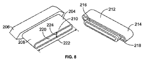
図7は、別の実施形態によるオストミー器具200を示している。オストミー器具200は、オストミーパウチ202及び平坦な排出タップ204を含んでいる。オストミーパウチ202は、任意のツーピース又はワンピースの従来の単一のチャンバーのオストミーパウチであるものとすることができる。平坦な排出タップ204は、平坦な排出タップ14と同様に、概ね平坦な輪郭を有している。平坦な排出タップ204は、オストミーパウチ202のテール部分210に嵌まるようになっている上部206と、扁平な円筒形状を有する底部208とを含んでいる。1つの実施形態では、底部208は、2よりも大きく、好ましくは4よりも大きい、厚さ224に対する幅222の比を有している。平坦な排出タップ204は、平坦な排出タップ14と同様に、シリコーン、ゴム、エラストマー等のような可撓性の弾性材料から形成される。
FIG. 7 shows an
オストミー器具200はクロージャーキャップ212も含み、クロージャーキャップ212は、平坦な排出タップ204の出口端部210の内側及び外側の両方に嵌まるようになっているものとすることができ、クロージャーキャップ212が平坦な排出タップ204に係合すると、2箇所の漏れのないシールを提供する。クロージャーキャップ212は、外側壁214と、外側壁214の中央に配置されている突出挿入部分216とを含んでいる。クロージャーキャップ212が排出タップに係合すると、挿入部分216は、平坦な排出タップ204の底部208がクロージャーキャップ212の外側壁214と挿入部分216との間に画定されるキャビティ218内に位置するように、平坦な排出タップ204の内腔220内に挿入される。したがって、クロージャーキャップ212は、平坦な排出タップ201に係合すると、底部208の内側及び外側の両方に嵌まり、2箇所の漏れのないシールを提供する。クロージャーキャップ212は、平坦な排出タップ204につなぐことができる。
The
図8に示されるように、平坦な排出タップ204は、概ね平坦であり比較的小さい断面厚さを有する内腔220を含んでいる。したがって、内腔を通る排出物の流れを制限することができる。平坦な排出タップ204は、内腔220のサイズを増大させることによって排出物の流れを手動で制御することができるように構成されている。図9に示されるように、平坦な排出タップ204のその側部を押して内腔220の流れ面積を増大させることができる。加える圧力の量を制御することによって、内腔220のサイズを制御することができる。図9は、ストーマからの排出物の最大限の流れを可能にするように完全に開いた内腔220を示している。オストミーパウチ202からの排出物を収集容器(図示せず)内へ連続的に排出するように、チューブ又はアダプター(図示せず)を平坦な排出タップ204に接続することができる。平坦な排出タップ204は、図10に示されている排出タップのような従来の円筒形の排出タップに比して、押されて開いたときに大幅により大きい内腔を提供することができる。加えて、可撓性である平坦な排出タップは、詰まるリスクを大幅に低減することができる。幾つかの実施形態では、平坦な排出タップは、平坦な排出タップの内面同士が互いに接触する、最初は閉じた内腔を有する。したがって、平坦な排出タップは、閉じた内腔の位置では、ストーマからの排出物の流れを大幅に制限するか又は止めることができる。
As shown in FIG. 8, the
本明細書において引用した全ての特許は、本開示の本文においてそれ自体具体的に示されるか否かにかかわらず、参照によりそれらの全体が本明細書に援用される。 All patents cited herein are hereby incorporated by reference in their entirety, whether or not specifically indicated in the text of the disclosure.
本開示において、「1つ」という用語は、単数形及び複数形の双方を含むように解釈されるべきである。反対に、複数の要素へのいかなる言及も、適切であれば、単数形を含むものとする。 In this disclosure, the term “a” should be construed to include both the singular and plural. On the contrary, any reference to a plurality of elements shall include the singular form where appropriate.
上記から、本開示の新規の概念の真の主旨及び範囲から逸脱することなく、多くの変更形態及び変形形態を達成することができることが分かるであろう。図示された特定の実施形態に対する限定は意図されず、推察もされるべきではないことを理解されたい。本開示は、添付の特許請求の範囲によって、特許請求の範囲に入るような全ての変更形態を包含することが意図される。 From the foregoing, it will be appreciated that many variations and modifications may be achieved without departing from the true spirit and scope of the novel concepts of the present disclosure. It should be understood that no limitation to the particular embodiments illustrated is intended or should be inferred. The present disclosure is intended to encompass all such modifications as fall within the scope of the appended claims.
Claims (15)
前記パウチ出口に取り付けられている平坦な排出タップであって、少なくとも1つの入口と、1つの出口と、前記身体の老廃物が前記パウチから流れ出るための経路を提供する内腔とを有する排出タップと
を備え、
該排出タップは、前記内腔のサイズが調整可能であるように構成され、
前記少なくとも1つの入口は、前記外側チャンバー内の前記身体の老廃物を受け入れるように構成されている第1の入口と、前記身体側チャンバー内の前記身体の老廃物を受け入れるように構成されている第2の入口とを含むオストミー器具。 A pouch including a pouch inlet for receiving bodily waste from the stoma , a pouch outlet , a body side chamber, and an outer chamber ;
A flat discharge taps attached to the pouch outlet, the discharge tap having a lumen for providing at least one inlet, one outlet, a path for waste of the body flows out of the pouch And
The drain tap is configured such that the size of the lumen is adjustable ;
The at least one inlet is configured to receive a first inlet configured to receive the bodily waste in the outer chamber and to receive the bodily waste in the body side chamber. An ostomy appliance including a second inlet .
Applications Claiming Priority (3)
| Application Number | Priority Date | Filing Date | Title |
|---|---|---|---|
| US201161521605P | 2011-08-09 | 2011-08-09 | |
| US61/521,605 | 2011-08-09 | ||
| PCT/US2012/047177 WO2013022575A1 (en) | 2011-08-09 | 2012-07-18 | Ostomy appliance |
Publications (3)
| Publication Number | Publication Date |
|---|---|
| JP2014521475A JP2014521475A (en) | 2014-08-28 |
| JP2014521475A5 JP2014521475A5 (en) | 2015-07-23 |
| JP6027115B2 true JP6027115B2 (en) | 2016-11-16 |
Family
ID=47668791
Family Applications (1)
| Application Number | Title | Priority Date | Filing Date |
|---|---|---|---|
| JP2014525030A Active JP6027115B2 (en) | 2011-08-09 | 2012-07-18 | Ostomy appliance |
Country Status (7)
| Country | Link |
|---|---|
| US (2) | US9993363B2 (en) |
| EP (1) | EP2741719B1 (en) |
| JP (1) | JP6027115B2 (en) |
| AU (1) | AU2012294882B2 (en) |
| CA (1) | CA2844616C (en) |
| DK (1) | DK2741719T3 (en) |
| WO (1) | WO2013022575A1 (en) |
Families Citing this family (22)
| Publication number | Priority date | Publication date | Assignee | Title |
|---|---|---|---|---|
| US9999536B2 (en) * | 2010-12-27 | 2018-06-19 | Benson Turtleneck Barrier Llc | Ostomy barrier seal |
| DK2741719T3 (en) * | 2011-08-09 | 2017-08-28 | Hollister Inc | An ostomy appliance |
| US9833352B2 (en) | 2011-08-23 | 2017-12-05 | Mayo Foundation For Medical Education And Research | Ostomy devices |
| USD754332S1 (en) * | 2012-08-13 | 2016-04-19 | Andreas Fahl Medizintechnik—Vertrieb GmbH | Plaster for tracheostoma |
| GB2512655B (en) * | 2013-04-05 | 2017-10-25 | Salts Healthcare Ltd | Ostomy appliance |
| USD746978S1 (en) * | 2013-06-26 | 2016-01-05 | Coloplast A/S | Ostomy bag |
| USD753820S1 (en) * | 2013-06-26 | 2016-04-12 | Coloplast A/S | Ostomy bag |
| KR20160147898A (en) * | 2014-04-24 | 2016-12-23 | 컨바텍 테크놀러지스 인크 | Ostomy pouch filter system |
| USD778435S1 (en) * | 2015-04-22 | 2017-02-07 | Heath J. Grogan | Combination stoma engaging pad and colostomy bag |
| CN105012066B (en) * | 2015-06-23 | 2017-04-19 | 广东省工业贸易职业技术学校 | Composite bag for stoma pack and collection bag for incontinent dermatitis liquid around stoma |
| EP3181101A1 (en) * | 2015-12-17 | 2017-06-21 | Dalina Medtech AB | Ostomy bag system |
| CA3013462C (en) * | 2016-02-05 | 2021-10-05 | Hollister Incorporated | Retractable outlet for ostomy pouch |
| EP3544554B1 (en) * | 2016-11-22 | 2024-04-17 | Hollister Incorporated | Drainage system for ostomy pouch |
| JP7066301B2 (en) * | 2017-01-20 | 2022-05-13 | ホリスター・インコーポレイテッド | Drainage ostomy pouch |
| GB2566721B (en) * | 2017-09-22 | 2020-07-15 | Salts Healthcare Ltd | An ostomy appliance |
| GB201715394D0 (en) * | 2017-09-22 | 2017-11-08 | Salts Healthcare Ltd | An ostomy appliance |
| US11491042B2 (en) | 2017-11-09 | 2022-11-08 | 11 Health And Technologies Limited | Ostomy monitoring system and method |
| USD893514S1 (en) | 2018-11-08 | 2020-08-18 | 11 Health And Technologies Limited | Display screen or portion thereof with graphical user interface |
| USD1012280S1 (en) * | 2018-11-30 | 2024-01-23 | B. Braun Medical Sas | Ostomy device assembly |
| CN114072110B (en) | 2019-04-25 | 2024-03-08 | 康沃特克科技公司 | Perforated chamber ostomy wafer, ostomy device comprising a perforated chamber ostomy wafer and method of application |
| EP4218691A1 (en) | 2019-10-04 | 2023-08-02 | ConvaTec Limited | Ostomy appliance |
| WO2021064406A1 (en) | 2019-10-04 | 2021-04-08 | Convatec Limited | Ostomy appliance |
Family Cites Families (32)
| Publication number | Priority date | Publication date | Assignee | Title |
|---|---|---|---|---|
| US2875451A (en) * | 1955-07-11 | 1959-03-03 | Stegeman Wilson | Flexible urinal |
| US3523534A (en) | 1967-04-05 | 1970-08-11 | Hollister Inc | Closure for drainage pouch |
| US3724461A (en) * | 1971-10-20 | 1973-04-03 | M Eisenberg | Container with self-closing one-way valve |
| US3825005A (en) * | 1973-02-26 | 1974-07-23 | Marlen Mfg And Dev Co | Resealable closure for ileostomy bag |
| US4280498A (en) | 1979-10-22 | 1981-07-28 | Hollister Incorporated | Valved drain assembly for urostomy pouch |
| US4411659A (en) | 1982-03-16 | 1983-10-25 | Hollister Incorporated | Drainable collection pouch and filter assembly therefor |
| GB2139501B (en) | 1983-04-14 | 1987-01-28 | Craig Med Prod Ltd | Ostomy bag, particularly for ileostomy patients |
| US4596566A (en) | 1984-10-26 | 1986-06-24 | Kay Dennis M | Ostomy appliance with suction securing chamber |
| US4592750A (en) | 1984-10-26 | 1986-06-03 | Kay Dennis M | Ostomy appliance |
| USD295220S (en) | 1985-02-12 | 1988-04-12 | Kay Dennis M | Drain valve for ostomy receptacles |
| US4668227A (en) | 1985-05-08 | 1987-05-26 | Kay Dennis M | Stoma hygiene system and process therefor |
| WO1987006823A1 (en) | 1986-05-12 | 1987-11-19 | Kay Dennis M | Ostomy appliance |
| JPS63189217U (en) | 1987-05-29 | 1988-12-05 | ||
| US5085652A (en) | 1989-06-16 | 1992-02-04 | E. R. Squibb & Sons | Pouch with mounting member for removable adhesive filter |
| GB2265832B (en) | 1992-04-08 | 1995-10-11 | Ronald Frederick Bettison | Ostomy bags |
| US5306264A (en) | 1993-01-14 | 1994-04-26 | E. R. Squibb & Sons, Inc. | Ostomy bag with multi-stage filter |
| US5356400A (en) | 1993-05-06 | 1994-10-18 | Temple John E | Large bore drainage apparatus |
| US5348546A (en) | 1993-05-21 | 1994-09-20 | Norton Walter L | Ostomy bag with liquid-gas separation device |
| US5772644A (en) * | 1993-12-28 | 1998-06-30 | Microtek Medical, Inc. | Filter pouch for stone and tissue sample collection |
| US5698623A (en) * | 1994-04-28 | 1997-12-16 | Jacobs; Richard L. | Resin precursors having thixotropic properties and fillers stabilized against settling |
| FR2735360B1 (en) | 1995-06-14 | 1997-12-19 | Cailleteau Benoit | SAFETY POCKET, ESPECIALLY HYGIENIC |
| USD396731S (en) | 1996-04-04 | 1998-08-04 | Mirto Clorinda M | Urostomy bag drainage valve |
| US5690623A (en) * | 1997-01-13 | 1997-11-25 | Dansac A/S | Vented ostomy pouch with protected gas filter |
| US6070767A (en) | 1998-07-17 | 2000-06-06 | Camelbak Products, Inc. | Personal hydration system with an improved mouthpiece |
| US6887222B2 (en) | 2002-02-08 | 2005-05-03 | Hollistser Incorporated | Ostomy pouch with bias members and closure means |
| DK174983B1 (en) * | 2002-04-10 | 2004-04-05 | Hollister Inc | Empty ostomy bag with integrated closure |
| DK175390B1 (en) | 2002-04-17 | 2004-09-20 | Coloplast As | Collection bag with improved recording means for a closure device |
| GB2391175B (en) * | 2002-07-04 | 2005-12-28 | Bristol Myers Squibb Co | Pouch for collecting human waste |
| JP2007082697A (en) | 2005-09-21 | 2007-04-05 | Alcare Co Ltd | Medical pouch |
| US20080033379A1 (en) | 2006-04-29 | 2008-02-07 | Pedersen Jes L | Drainable ostomy pouch with bias members and closure means |
| US20070265588A1 (en) * | 2006-05-15 | 2007-11-15 | Pedersen Jes L | Drainable ostomy pouch with integrated closure |
| DK2741719T3 (en) * | 2011-08-09 | 2017-08-28 | Hollister Inc | An ostomy appliance |
-
2012
- 2012-07-18 DK DK12822013.4T patent/DK2741719T3/en active
- 2012-07-18 WO PCT/US2012/047177 patent/WO2013022575A1/en active Application Filing
- 2012-07-18 EP EP12822013.4A patent/EP2741719B1/en active Active
- 2012-07-18 JP JP2014525030A patent/JP6027115B2/en active Active
- 2012-07-18 CA CA2844616A patent/CA2844616C/en active Active
- 2012-07-18 AU AU2012294882A patent/AU2012294882B2/en active Active
- 2012-07-18 US US14/237,541 patent/US9993363B2/en active Active
-
2018
- 2018-05-02 US US15/969,488 patent/US11090185B2/en active Active
Also Published As
| Publication number | Publication date |
|---|---|
| EP2741719A1 (en) | 2014-06-18 |
| AU2012294882A1 (en) | 2014-02-27 |
| US20140194843A1 (en) | 2014-07-10 |
| US9993363B2 (en) | 2018-06-12 |
| DK2741719T3 (en) | 2017-08-28 |
| AU2012294882B2 (en) | 2016-07-21 |
| CA2844616C (en) | 2019-12-31 |
| EP2741719B1 (en) | 2017-05-03 |
| JP2014521475A (en) | 2014-08-28 |
| US20180250157A1 (en) | 2018-09-06 |
| CA2844616A1 (en) | 2013-02-14 |
| WO2013022575A1 (en) | 2013-02-14 |
| EP2741719A4 (en) | 2015-04-01 |
| US11090185B2 (en) | 2021-08-17 |
Similar Documents
| Publication | Publication Date | Title |
|---|---|---|
| JP6027115B2 (en) | Ostomy appliance | |
| EP3544554B1 (en) | Drainage system for ostomy pouch | |
| EP2566421B1 (en) | Ostomy port gas release mechanism | |
| US7367965B2 (en) | Ostomy appliance with multiple openings for preventing filter input blockage | |
| US4084590A (en) | Stoma drainage appliance | |
| JP2014521475A5 (en) | ||
| US4238059A (en) | Stoma drainage appliance | |
| AU2013235175A1 (en) | Expandable ostomy appliance | |
| US20150018789A1 (en) | Washable ostomy pouch ii | |
| US7828269B2 (en) | Disposable valve unit for regulating a flow of urine | |
| US6007525A (en) | Filtering and deodorizing device for use with colostomy pouch | |
| US20140371699A1 (en) | Closed ostomy bag system | |
| US11883317B2 (en) | Ostomy appliance | |
| CN215020186U (en) | Colon fistulization bag | |
| US8282613B2 (en) | Disposable urine bag for collecting urine | |
| CA3171919A1 (en) | Ostomy bag vent system for use in venting a gas from an interior of an ostomy collection pouch | |
| AU2021387892B2 (en) | Ostomy product with anti-reflux device | |
| US20240065877A1 (en) | Ostomy bag vent system for use in venting a gas from an interior of an ostomy collection pouch | |
| CA1066580A (en) | Spout for a fluid container |
Legal Events
| Date | Code | Title | Description |
|---|---|---|---|
| A521 | Request for written amendment filed |
Free format text: JAPANESE INTERMEDIATE CODE: A523 Effective date: 20150605 |
|
| A621 | Written request for application examination |
Free format text: JAPANESE INTERMEDIATE CODE: A621 Effective date: 20150605 |
|
| A131 | Notification of reasons for refusal |
Free format text: JAPANESE INTERMEDIATE CODE: A131 Effective date: 20160216 |
|
| A977 | Report on retrieval |
Free format text: JAPANESE INTERMEDIATE CODE: A971007 Effective date: 20160219 |
|
| A521 | Request for written amendment filed |
Free format text: JAPANESE INTERMEDIATE CODE: A523 Effective date: 20160513 |
|
| TRDD | Decision of grant or rejection written | ||
| A01 | Written decision to grant a patent or to grant a registration (utility model) |
Free format text: JAPANESE INTERMEDIATE CODE: A01 Effective date: 20160913 |
|
| A61 | First payment of annual fees (during grant procedure) |
Free format text: JAPANESE INTERMEDIATE CODE: A61 Effective date: 20161013 |
|
| R150 | Certificate of patent or registration of utility model |
Ref document number: 6027115 Country of ref document: JP Free format text: JAPANESE INTERMEDIATE CODE: R150 |
|
| R250 | Receipt of annual fees |
Free format text: JAPANESE INTERMEDIATE CODE: R250 |
|
| R250 | Receipt of annual fees |
Free format text: JAPANESE INTERMEDIATE CODE: R250 |
|
| R250 | Receipt of annual fees |
Free format text: JAPANESE INTERMEDIATE CODE: R250 |
|
| R250 | Receipt of annual fees |
Free format text: JAPANESE INTERMEDIATE CODE: R250 |
|
| R250 | Receipt of annual fees |
Free format text: JAPANESE INTERMEDIATE CODE: R250 |