EP2741719B1 - Appareil pour stomie - Google Patents
Appareil pour stomie Download PDFInfo
- Publication number
- EP2741719B1 EP2741719B1 EP12822013.4A EP12822013A EP2741719B1 EP 2741719 B1 EP2741719 B1 EP 2741719B1 EP 12822013 A EP12822013 A EP 12822013A EP 2741719 B1 EP2741719 B1 EP 2741719B1
- Authority
- EP
- European Patent Office
- Prior art keywords
- inlet
- pouch
- output tap
- ostomy appliance
- sealing surface
- Prior art date
- Legal status (The legal status is an assumption and is not a legal conclusion. Google has not performed a legal analysis and makes no representation as to the accuracy of the status listed.)
- Active
Links
- 238000007789 sealing Methods 0.000 claims description 33
- 239000007788 liquid Substances 0.000 claims description 30
- 239000007787 solid Substances 0.000 claims description 29
- 239000002699 waste material Substances 0.000 claims description 18
- 238000001914 filtration Methods 0.000 claims description 16
- 230000002093 peripheral effect Effects 0.000 claims description 4
- 240000008100 Brassica rapa Species 0.000 claims 1
- 239000000853 adhesive Substances 0.000 description 6
- 230000001070 adhesive effect Effects 0.000 description 6
- 229920001971 elastomer Polymers 0.000 description 4
- 230000004888 barrier function Effects 0.000 description 3
- 238000003780 insertion Methods 0.000 description 3
- 230000037431 insertion Effects 0.000 description 3
- 239000000463 material Substances 0.000 description 3
- 239000000806 elastomer Substances 0.000 description 2
- 239000010808 liquid waste Substances 0.000 description 2
- 238000000034 method Methods 0.000 description 2
- 238000012986 modification Methods 0.000 description 2
- 230000004048 modification Effects 0.000 description 2
- 230000000737 periodic effect Effects 0.000 description 2
- 229920001296 polysiloxane Polymers 0.000 description 2
- 239000012858 resilient material Substances 0.000 description 2
- 230000008591 skin barrier function Effects 0.000 description 2
- 238000004891 communication Methods 0.000 description 1
- 238000007796 conventional method Methods 0.000 description 1
- 239000012530 fluid Substances 0.000 description 1
- 238000007455 ileostomy Methods 0.000 description 1
- 239000000203 mixture Substances 0.000 description 1
- 238000000465 moulding Methods 0.000 description 1
- 230000000717 retained effect Effects 0.000 description 1
- 239000002910 solid waste Substances 0.000 description 1
Images

Classifications
-
- A—HUMAN NECESSITIES
- A61—MEDICAL OR VETERINARY SCIENCE; HYGIENE
- A61F—FILTERS IMPLANTABLE INTO BLOOD VESSELS; PROSTHESES; DEVICES PROVIDING PATENCY TO, OR PREVENTING COLLAPSING OF, TUBULAR STRUCTURES OF THE BODY, e.g. STENTS; ORTHOPAEDIC, NURSING OR CONTRACEPTIVE DEVICES; FOMENTATION; TREATMENT OR PROTECTION OF EYES OR EARS; BANDAGES, DRESSINGS OR ABSORBENT PADS; FIRST-AID KITS
- A61F5/00—Orthopaedic methods or devices for non-surgical treatment of bones or joints; Nursing devices; Anti-rape devices
- A61F5/44—Devices worn by the patient for reception of urine, faeces, catamenial or other discharge; Portable urination aids; Colostomy devices
- A61F5/445—Colostomy, ileostomy or urethrostomy devices
-
- A—HUMAN NECESSITIES
- A61—MEDICAL OR VETERINARY SCIENCE; HYGIENE
- A61F—FILTERS IMPLANTABLE INTO BLOOD VESSELS; PROSTHESES; DEVICES PROVIDING PATENCY TO, OR PREVENTING COLLAPSING OF, TUBULAR STRUCTURES OF THE BODY, e.g. STENTS; ORTHOPAEDIC, NURSING OR CONTRACEPTIVE DEVICES; FOMENTATION; TREATMENT OR PROTECTION OF EYES OR EARS; BANDAGES, DRESSINGS OR ABSORBENT PADS; FIRST-AID KITS
- A61F5/00—Orthopaedic methods or devices for non-surgical treatment of bones or joints; Nursing devices; Anti-rape devices
- A61F5/44—Devices worn by the patient for reception of urine, faeces, catamenial or other discharge; Portable urination aids; Colostomy devices
- A61F5/4404—Details or parts
- A61F5/4405—Valves or valve arrangements specially adapted therefor ; Fluid inlets or outlets
-
- A—HUMAN NECESSITIES
- A61—MEDICAL OR VETERINARY SCIENCE; HYGIENE
- A61F—FILTERS IMPLANTABLE INTO BLOOD VESSELS; PROSTHESES; DEVICES PROVIDING PATENCY TO, OR PREVENTING COLLAPSING OF, TUBULAR STRUCTURES OF THE BODY, e.g. STENTS; ORTHOPAEDIC, NURSING OR CONTRACEPTIVE DEVICES; FOMENTATION; TREATMENT OR PROTECTION OF EYES OR EARS; BANDAGES, DRESSINGS OR ABSORBENT PADS; FIRST-AID KITS
- A61F5/00—Orthopaedic methods or devices for non-surgical treatment of bones or joints; Nursing devices; Anti-rape devices
- A61F5/44—Devices worn by the patient for reception of urine, faeces, catamenial or other discharge; Portable urination aids; Colostomy devices
- A61F5/4404—Details or parts
- A61F5/4407—Closure means other than valves
-
- A—HUMAN NECESSITIES
- A61—MEDICAL OR VETERINARY SCIENCE; HYGIENE
- A61F—FILTERS IMPLANTABLE INTO BLOOD VESSELS; PROSTHESES; DEVICES PROVIDING PATENCY TO, OR PREVENTING COLLAPSING OF, TUBULAR STRUCTURES OF THE BODY, e.g. STENTS; ORTHOPAEDIC, NURSING OR CONTRACEPTIVE DEVICES; FOMENTATION; TREATMENT OR PROTECTION OF EYES OR EARS; BANDAGES, DRESSINGS OR ABSORBENT PADS; FIRST-AID KITS
- A61F5/00—Orthopaedic methods or devices for non-surgical treatment of bones or joints; Nursing devices; Anti-rape devices
- A61F5/44—Devices worn by the patient for reception of urine, faeces, catamenial or other discharge; Portable urination aids; Colostomy devices
- A61F5/441—Devices worn by the patient for reception of urine, faeces, catamenial or other discharge; Portable urination aids; Colostomy devices having venting or deodorant means, e.g. filters ; having antiseptic means, e.g. bacterial barriers
Definitions
- the present disclosure relates to ostomy appliances of the kind disclosed in claim 1.
- Ostomy pouches for the collection of body waste output from a stoma are well known. Ostomy pouches typically include flat, opposing side walls secured together along their edges to define a human stomal discharge collection cavity. One of the side walls is provided with an opening to receive a stoma, and means such as a connecting flange is provided for securing the pouch to an adhesive barrier placed to surround the stoma so that body waste discharged through the stoma will be received within the cavity.
- the ostomy pouch may have a discharge opening which may be closed during collection of body waste that passes through the stoma but may be opened for draining the body waste from the pouch after a period of use.
- the ostomy pouch may be designed for a single use in which case it will not be provided with a discharge opening since the entire pouch will be discarded after it has substantially filled with human stomal discharge.
- a drainable ostomy pouch comprising a first or proximal and a second or distal side wall of flexible sheet material sealed to each other for defining a cavity therebetween for receiving human stomal discharge through an aperture in the proximal side wall and an elongate drainage portion extending downwardly in a longitudinal direction and ending in a drainage opening extending transversely to the longitudinal direction, a first or proximal and a second or distal flexible stiffening strip extending immediately adjacent to and along said drainage opening and are attached for instance by heat sealing or adhesion to the outer surface of the first and second side walls, respectively, of said drainage portion.
- a drainable pouch is typically reusable following periodic emptying of the body waste by utilizing a closure for the discharge opening.
- Such closures may take a number of different forms so long as it serves to prevent leakage of the body waste.
- Some drainable pouches are designed to be coupled to drainage tubes leading to relatively large volume bedside containers. These permit stoma discharge to drain continuously through the pouch into the container so that, for example, the user can sleep through the night without periodic need to empty the contents of the ostomy pouch.
- Such drainable pouches include an output tap for connecting to a drainage tube, either directly or via an adapter. Output taps typically have a generally cylindrical shape and a circular cross-sectional area. They are bulky under clothing and can have difficulty passing large pieces of solid matters. This can often lead to user discomfort and clogged night time drainage systems.
- such an ostomy appliance can separate solid matter from liquid waste. More desirably, such an appliance includes an outlet that can discharge liquid waste separate from or in conjunction with solid waste from the ostomy pouch.
- Drainable ostomy pouches which can connect to an external container for continuous drainage of pouch contents have been used for ostomy patients.
- ileostomy patients have used high output drainable ostomy pouches, which include an output tap for draining stoma discharge, which is typically a mixture of liquids and solids.
- Output taps for high output drainable pouches typically have a generally cylindrical shape with a circular cross-sectional area, and are formed of a polymeric material that maintains a cylindrical lumen.
- these output taps are bulky under clothing and often become clogged when attached to a night drain collector. This can cause leakage and disrupt a user's sleep.
- the ostomy appliance includes an ostomy pouch configured to separate solids and liquids in stoma discharge and allow separated liquids to continuously drain while keeping solids in the pouch to reduce the risk of the output tap becoming clogged.
- solids are retained in a body side chamber and liquids flow into an outer chamber of the ostomy pouch.
- the ostomy appliance can include a liquid valve or tap on the outer chamber for connecting to a night drainage container to drain liquids from the outer chamber.
- the ostomy pouch also includes an outlet, which can be opened to drain all outputs, such as a drainable fold-up type closure.
- the ostomy appliance includes a high output tap that has a generally flat profile, which lays flat against the user.
- a high output tap is less bulky than conventional high output taps and provides a higher degree of discretion for the user.
- the output tap of the present invention includes a lumen, the size of which can be increased to accommodate larger solids, thereby reducing a risk of clogging.
- the output tap includes a closure cap that may fit both inside and outside of a tap outlet to provide a secure, two-location seal when the closure cap is engaged with the tap.
- a flat high output tap is configured to connect to a night drainage tube directly or via an adapter to drain liquids from the ostomy pouch. The same flat high output tap can be opened to empty both liquids and solids in the ostomy pouch.
- the present invention relates to an ostomy appliance as claimed in claim 1.
- an ostomy appliance in an example (not falling under the scope of the present invention) includes a pouch, which includes a first chamber and a second chamber, an inlet, at least one outlet, and a filter configured to separate liquids and solids in body waste received via the inlet.
- an ostomy appliance in another example (not falling under the scope of the present invention) includes a pouch, which includes a first chamber and a second chamber, a pouch inlet, a pouch outlet, and a flat output tap.
- the flat output tap is attached to the pouch outlet, and includes at least one inlet, an outlet, and a lumen providing a path for the body waste to flow out of the pouch.
- the flat output tap is configured such that a size of the lumen is adjustable.
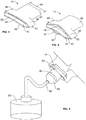
- the ostomy appliance 10 includes an ostomy pouch 12 and a flat output tap 14.
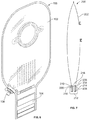
- the ostomy pouch 12 is a dual-chamber pouch including a body side chamber 16 and an outer chamber 18.
- the ostomy pouch 12 includes flat, opposing side walls, namely a body side wall 20 and an outer wall 22, and a center wall 24, which includes a separating or filtering section 26.
- the opposing side walls 20, 22, and the center wall 24 are secured together along their edges 28, for example via heat sealing, to define the body side chamber 16 and the outer chamber 18.
- the body side wall 20 is provided with an inlet opening 30 to receive a stoma, and a pouch side connecting flange 32 for securing the ostomy pouch 10 to an adhesive barrier (not shown) placed around the stoma via a body side connecting flange (not shown) so that body waste material discharged through the stoma is received within the body side chamber 16 of the ostomy pouch 12.
- this embodiment is shown as a two-piece ostomy appliance including the pouch side connecting flange 32 and the separate adhesive barrier including the body side connecting flange (not shown), in other embodiments, the ostomy appliance may be a one piece pouch, wherein an adhesive skin barrier is directly attached to the pouch.
- the filtering section 20 is configured to separate liquids from solids in body waste entering the body side chamber 16 via the inlet opening 30.
- the filtering section 20 includes a plurality of openings, for example, a plurality of perforations or slits, to allow liquids to pass through the filtering section into the outer chamber 18, but block solids from passing through the filtering section 20.
- the filtering section 20 includes plurality of circular openings, each opening may have a diameter between about 1 mm and about 5 mm, for example, between about 2 mm and about 4 mm.
- the filtering section may have different shape and/or size openings to accommodate different body wastes to effectively separate liquids from solids.
- the size of the openings may be smaller than 1 mm diameter.
- the ostomy appliance 10 includes a tail portion 33.
- the flat output tap 14 is arranged in the tail portion 33 and is sealingly attached to inner surfaces of the peripheral end of the tail portion 33.
- a perspective view of the flat output tap 14 is shown in FIG. 3 .
- the flat output tap 14 is a one-piece tap formed of a flexible, resilient material via a conventional molding process.
- Su Caribbean materials for the flat output tap 14 include, but not limited to, silicone, rubber, elastomers and the like.
- the flat output tap 14 has a generally flat profile, and includes a lumen 48 defining an outlet path for stoma discharge to exit the ostomy pouch 12.
- the term "generally flat profile" is used herein to describe a shape of the output tap that has a width:thickness ratio of at least 2, wherein the width 64 ( FIG. 3 ) and the thickness 66 ( FIG. 2 ) are measured at the outlet end of the output tap, such that the output tap lays flat when the ostomy appliance is worn by the user to provide the user with a greater degree of discretion when compared to conventional output taps having circular cross-sectional areas.
- the flat output tap 14 has a top portion 44, which is configured to fit in the peripheral end of the tail portion 33 of the ostomy pouch 12, and a bottom portion 46 defining a discharge outlet 34.
- the bottom portion 46 has a flattened cylinder-like shape, such that in a relaxed state, the width 64 ( FIG. 3 ) is greater than the thickness 66 ( FIG. 2 ). In the illustrated embodiment, the width 64 to thickness 66 ratio of the bottom portion 46 is greater than 2, and preferably greater than 4.
- the top portion 44 may include three sealing surfaces 38, 40, 42 for sealing against the pouch walls 22, 24, 20.
- a first sealing surface 38 and a second sealing surface 40 are formed on one side of the flat output tap 14, and a third sealing surface 42 is formed on the opposite side of the output tap 14.
- the top portion 44 includes a first lip 50 and a second lip 51.
- the second sealing surface 40 is formed on the first lip 50, and the third sealing surface 42 is formed on the second lip 51.
- the lips 50, 51 are in contact with each other in a closed lip position as shown in FIGS. 2-3 , until pressure is applied along edges 52 of the top portion 44 to open the lips 50, 51, as shown in FIGS. 1 , 3, and 4 .
- the user can press edges 52 with his fingers to open the lips 50, 51.
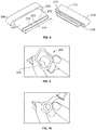
- FIG. 4 shows the flat output tap 14 in an open position.
- the lips 50, 51 define an inlet from the body side chamber 16, which remains closed until pressure is applied to open the inlet.
- An opening 54 arranged between the first sealing surface 38 and the second sealing surface 40 defines a liquid inlet from the outer chamber 18.
- the flat output tap 14 is arranged in the tail portion 33 of the ostomy pouch 12 such that the first sealing surface 38 faces an inner surface of the outer wall 22, the second sealing surface 40 faces a body side surface of the center wall 24, and the third sealing surface 42 faces an inner surface of the body side wall 20.
- the first sealing surface 38 is sealingly attached to the inner surface of the outer wall 22.
- the second sealing surface 40 is sealingly attached to the surface of the center wall 24, which faces the body side chamber 16.
- the third sealing surface 42 is sealingly attached to the inner surface of the body side wall 20.
- the sealing surfaces 38, 40, 42 can be attached to the walls 22, 24, 20 using conventional methods, such as heat sealing or adhesives.
- the ostomy appliance 10 can include a closure cap 36 ( FIG. 1 ), which may fit both inside and outside of an outlet end portion 35 of the flat output tap 14, to provide a wo-location, leak free seal when the closure cap 36 is engaged with the flat output tap 14.
- the closure cap 36 may be tethered to the flat output tap 14.
- the ostomy appliance 10 which is sealingly closed with the closure cap 36, is attached to the adhesive skin barrier (not shown.)
- Stoma discharge flows in via the opening 30 into the body side chamber 16.
- the stoma discharge typically includes both liquids and solids.
- the liquids in the stoma discharge flows into the outer chamber 18 from the body side chamber 16 through the center wall filtering section 26.
- the stoma discharge is generally separated into liquids and solids via the filtering section 26.
- an adapter 58 is engaged with the discharge outlet 34 for draining body waste in the ostomy pouch 12 to a collection container 60 via tube 62.
- an outlet 56 of the body side chamber 16 is closed by the closed lips 50, 51 of the flat output tap 14, which prevents solids in the body side chamber 16 from flowing through the discharge outlet 34.
- An outlet 57 of the outer chamber 18 is in fluid communication with the discharge outlet 34 via the opening 54 in the flat output tap 14.
- the liquids in the outer chamber 18 flow out through the discharge outlet 34, through the adapter 58, and into the collection container 60 via tube 62.
- only liquids, which are separated from solids via the filtering section 26, are continuously drained into the collection container 60.
- risk of the flat output tap 14, the adapter 58, and/or the tube 62 becoming clogged by solids is significantly reduced or eliminated.
- the flat output tap 14 can be pressed inwardly at edges 52, as shown in FIGS. 3 and 4 , which opens the lip 50, which in turn opens the outlet 56 of the body side chamber 16 to empty the solids.
- the opening 54 may remain open, so both liquids and solids can be drained via the discharge outlet 34 of the flat output tap 14.
- the bottom portion 46 can also be pressed on its edges to increase the size of the lumen 48 to improve draining of solids and liquids.
- FIG. 6 illustrates an ostomy appliance 100 according to an alternative embodiment. Similar to ostomy appliance 10, ostomy appliance 100 includes a dual-chamber ostomy pouch 102, which includes a body side chamber for solids and an outer chamber for liquids. However, instead of the flat output tap, ostomy appliance 100 includes a fold-up type closure 104 and a liquid valve 106. Examples of such a fold-up type closures are disclosed in Villefrance, et al., US Patent No. 7,879,015 , and Mandzij, et al., US Patent No. 7,879,016 .
- the chambers of the ostomy pouch 102 are defined by a body side wall, a center wall with a filtering section, and an outer wall.
- the fold-up type closure 104 is rolled up and closed, outlets of the body side chamber and the outer chamber are closed, and the chambers are separated by the center wall.
- solids and liquids in stoma discharge flowing into the body side chamber are generally separated as described above with regard to ostomy appliance 10.
- the outer chamber of the ostomy pouch 100 is provided with the liquid valve 106, through which the liquids in the outer chamber can be drained into a collection container (not shown.)
- the fold-up type closure 104 can be opened or unrolled, which opens outlets of the body side chamber and the outer chamber, and both liquids and solids can be emptied together.
- FIG. 7 illustrates an ostomy appliance 200 according to another embodiment.
- the ostomy appliance 200 includes an ostomy pouch 202 and a flat output tap 204.
- the ostomy pouch 202 may be any two-piece or one-piece conventional single chambered ostomy pouch.
- the flat output tap 204 has a generally flat profile.
- the flat output tap 204 includes a top portion 206, which is adapted to fit in a tail portion 210 of the ostomy pouch 202, and a bottom portion 208 having a flattened cylinder-like shape.
- the bottom portion 208 has a width 222 to thickness 224 ratio of greater 2, and preferably greater than 4.
- the flat output tap 204 is formed of a flexible, resilient material, such as silicone, rubber, elastomers, and the like.
- Ostomy appliance 200 also includes a closure cap 212, which may be adapted to fit both inside and outside of an outlet end portion 210 of the flat output tap 204 to provide a two-location, leak-free seal when the closure cap 212 is engaged with the flat output tap 204.
- the closure cap 212 includes an outer wall 214 and a protruding insertion portion 216 arranged in the center of the outer wall 214. When the cap 212 is engaged with the tap, the insertion portion 216 is inserted into a lumen 220 of the flat output tap 204, such that the bottom portion 208 of the flat output tap 204 is positioned in a cavity 218 defined between the outer wall 214 and the insertion portion 216 of the closure cap 212.
- the closure cap 212 fits both inside and outside of the bottom portion 208 to provide the two-location, leak free seal.
- the closure cap 212 may be tethered to the flat output tap 204.
- the flat output tap 204 includes the lumen 220, which is generally flat and has a relatively small cross-sectional thickness. Thus, flow of discharge through the lumen may be restricted.
- the flat output tap 204 is configured such that the flow of discharge can be manually controlled by increasing the size of the lumen 220. As shown in FIG. 9 , the flat output tap 204 can be pressed on its sides to increase the flow area of the lumen 220. By controlling the amount of the pressure applied, the size of the lumen 220 can be controlled.
- FIG. 9 shows the lumen 220 fully opened to allow maximum flow of stoma discharge.
- a tube or adapter (not shown) can be connected to the flat output tap 204 for continuous draining of the discharge from the ostomy pouch 202 into a collection container (not shown.)
- the flat output tap 204 can provide a significantly larger lumen, when pressed open, compared to conventional cylindrical output taps, such as the output tap shown in FIG. 10 .
- the flat output tap which is flexible, can significantly reduce the risk of clogging.
- the flat output tap has a lumen that is initially closed, in which the inner surfaces of the flat output tap are in contact with each other. As such the flat output tap can significantly restrict or stop the flow of stoma discharge in the closed lumen position.
Claims (15)
- Appareil pour stomie, comprenant :une poche (12), la poche (12) incluant un orifice d'entrée de poche (30) pour recevoir des déchets corporels provenant d'un estomac et une partie orifice de sortie de poche (33) ;dans lequel une prise de sortie plate (14) est agencée dans la partie orifice de sortie (33), la prise de sortie plate possédant au moins un orifice d'entrée, un orifice de sortie et une lumière créant un chemin pour que les déchets corporels s'écoulent à l'extérieur de la poche, dans lequel la prise de sortie plate est configurée de telle sorte qu'une taille de la lumière est réglable ;caractérisé en ce que la prise de sortie plate (14) est attachée aux surfaces intérieures de parois de poche dans la partie orifice de sortie de poche (33), et en ce que la prise de sortie plate (14) est une prise en une seule pièce.
- Appareil pour stomie selon la revendication 1, dans lequel la prise de sortie plate (14) présente un profil généralement plat, la prise de sortie (14) incluant une partie supérieure configurée pour s'insérer dans l'orifice de sortie de poche (34) et une partie inférieure (46), dans lequel la lumière est définie par les surfaces intérieures de la partie supérieure et les surfaces intérieures de la partie inférieure (46), l'au moins un orifice d'entrée étant défini dans la partie supérieure et l'orifice de sortie étant défini à une extrémité périphérique de la partie inférieure (46), et dans lequel la partie inférieure (46) a une forme analogue à un cylindre aplati, et, dans un état relâché, une largeur de la partie inférieure (46) est supérieure à une épaisseur de la partie inférieure (46).
- Appareil pour stomie selon la revendication 2, dans lequel un rapport de la largeur sur l'épaisseur de la partie inférieure (46) est, dans un état relâché, supérieur à 2.
- Appareil pour stomie selon la revendication 3, dans lequel le rapport de la largeur sur l'épaisseur de la partie inférieure (46) est, dans un état relâché, supérieur à 4.
- Appareil pour stomie selon l'une quelconque des revendications 1-4, dans lequel la poche est une poche à deux chambres comportant une paroi côté corps (20), une paroi extérieure (22) et une paroi centrale (24) incluant une section de filtrage (26), la paroi côté corps (20), la paroi extérieure (22) et la paroi centrale (24) étant scellées ensemble le long de leurs bords périphériques (28) afin de définir une chambre côté corps (16) et une chambre extérieure (18), la chambre côté corps (16) étant définie entre la paroi côté corps (20) et la paroi centrale (24), et la chambre extérieure (18) étant définie entre la paroi extérieure (22) et la paroi centrale (24), dans lequel la paroi côté corps (20) inclut l'orifice d'entrée de poche (30).
- Appareil pour stomie selon la revendication 5, dans lequel la section de filtrage (26) inclut une pluralité d'ouvertures, la section de filtrage étant configurée pour séparer les solides et les liquides contenus dans les déchets corporels, dans lequel les liquides s'écoulent depuis la chambre côté corps (16) jusque dans la chambre extérieure en passant par la section de filtrage (18), alors que pratiquement tous les solides restent dans la chambre côté corps (16).
- Appareil pour stomie selon la revendication 6, dans lequel la pluralité d'ouvertures est une pluralité de perforations ou une pluralité de fentes.
- Appareil pour stomie selon la revendication 6, dans lequel la section de filtration (26) inclut une pluralité d'ouvertures circulaires, chaque ouverture circulaire ayant un diamètre d'environ 2 mm à environ 4 mm.
- Appareil pour stomie selon l'une quelconque des revendications 5-8, dans lequel l'au moins un orifice d'entrée (30) inclut un premier orifice d'entrée et un deuxième orifice d'entrée, le premier orifice d'entrée étant configuré pour recevoir les déchets corporels dans la chambre extérieure (18) et le deuxième orifice d'entrée étant configuré pour recevoir les déchets corporels dans la chambre côté corps (16), dans lequel le deuxième orifice d'entrée est dans une position fermée jusqu'à ce qu'il soit ouvert par un utilisateur.
- Appareil pour stomie selon l'une quelconque des revendications 5-8, dans lequel au moins un orifice d'entrée (30) inclut un premier orifice d'entrée et un deuxième orifice d'entrée, la prise de sortie (14) incluant une partie supérieure agencée dans l'orifice de sortie de poche (34), la partie supérieure incluant une première surface d'étanchéité (38), une deuxième surface d'étanchéité (40) et une troisième surface d'étanchéité (42), la première surface d'étanchéité (38) étant attachée à une surface intérieure de la paroi extérieure (22) à proximité de l'orifice de sortie de poche (34), la deuxième surface d'étanchéité (40) étant attachée à une surface de la paroi centrale (24) à proximité de l'orifice de sortie de poche (34), la troisième surface d'étanchéité (42) étant attachée à une surface intérieure de la paroi côté corps (20), dans lequel le premier orifice d'entrée est défini entre la première surface d'étanchéité (38) et la deuxième surface d'étanchéité (40), et le deuxième orifice d'entrée est défini entre la deuxième surface d'étanchéité (40) et la troisième surface d'étanchéité (42).
- Appareil pour stomie selon la revendication 10, dans lequel la partie supérieure comprend une première lèvre (50) et une deuxième lèvre (51), la deuxième surface d'étanchéité (40) étant formée sur une surface extérieure de la première lèvre (50), la troisième surface d'étanchéité (42) étant formée sur une surface extérieure de la deuxième lèvre (51) et le deuxième orifice d'entrée étant défini entre la lèvre supérieure et la lèvre inférieure, dans lequel la première lèvre (50) et la deuxième lèvre (51) sont en contact l'une avec l'autre, de telle sorte que le deuxième orifice d'entrée est dans une position fermée, dans lequel la première lèvre (50) et la deuxième lèvre (51) sont configurées pour s'ouvrir en appliquant une pression le long de bords de la partie supérieure, et dans lequel le premier orifice d'entrée est défini par une ouverture agencée entre la première surface d'étanchéité (38) et la deuxième surface d'étanchéité (40).
- Appareil pour stomie selon la revendication 11, dans lequel l'orifice de sortie de la prise de sortie (14) est connecté à un tube pour transporter les déchets corporels jusqu'à un récipient, dans lequel les liquides dans la chambre extérieure (18) s'écoulent par le premier orifice d'entrée et sont transportés en continu jusqu'au récipient par le biais du tube, et dans lequel pratiquement tous les solides restent dans la chambre côté corps jusqu'à ce que le deuxième orifice d'entrée soit ouvert.
- Appareil pour stomie selon la revendication 12, dans lequel le tube est connecté à la prise de sortie par le biais d'un adaptateur, l'adaptateur étant configuré pour s'insérer dans l'orifice de sortie de la prise de sortie (14).
- Appareil pour stomie selon l'une quelconque des revendications 1-13, dans lequel la prise de sortie (14) est configurée de telle sorte qu'une taille de la lumière augmente en appliquant une pression sur les bords de la prise de sortie (14).
- Appareil pour stomie selon l'une quelconque des revendications 1-14, dans lequel la taille de la lumière et une taille de l'orifice de sortie augmentent en appliquant une pression le long de la largeur de la partie inférieure.
Applications Claiming Priority (2)
| Application Number | Priority Date | Filing Date | Title |
|---|---|---|---|
| US201161521605P | 2011-08-09 | 2011-08-09 | |
| PCT/US2012/047177 WO2013022575A1 (fr) | 2011-08-09 | 2012-07-18 | Appareil pour stomie |
Publications (3)
| Publication Number | Publication Date |
|---|---|
| EP2741719A1 EP2741719A1 (fr) | 2014-06-18 |
| EP2741719A4 EP2741719A4 (fr) | 2015-04-01 |
| EP2741719B1 true EP2741719B1 (fr) | 2017-05-03 |
Family
ID=47668791
Family Applications (1)
| Application Number | Title | Priority Date | Filing Date |
|---|---|---|---|
| EP12822013.4A Active EP2741719B1 (fr) | 2011-08-09 | 2012-07-18 | Appareil pour stomie |
Country Status (7)
| Country | Link |
|---|---|
| US (2) | US9993363B2 (fr) |
| EP (1) | EP2741719B1 (fr) |
| JP (1) | JP6027115B2 (fr) |
| AU (1) | AU2012294882B2 (fr) |
| CA (1) | CA2844616C (fr) |
| DK (1) | DK2741719T3 (fr) |
| WO (1) | WO2013022575A1 (fr) |
Families Citing this family (22)
| Publication number | Priority date | Publication date | Assignee | Title |
|---|---|---|---|---|
| US9999536B2 (en) * | 2010-12-27 | 2018-06-19 | Benson Turtleneck Barrier Llc | Ostomy barrier seal |
| DK2741719T3 (en) * | 2011-08-09 | 2017-08-28 | Hollister Inc | An ostomy appliance |
| US9833352B2 (en) | 2011-08-23 | 2017-12-05 | Mayo Foundation For Medical Education And Research | Ostomy devices |
| USD754332S1 (en) * | 2012-08-13 | 2016-04-19 | Andreas Fahl Medizintechnik—Vertrieb GmbH | Plaster for tracheostoma |
| GB2512655B (en) * | 2013-04-05 | 2017-10-25 | Salts Healthcare Ltd | Ostomy appliance |
| USD746978S1 (en) * | 2013-06-26 | 2016-01-05 | Coloplast A/S | Ostomy bag |
| USD753820S1 (en) * | 2013-06-26 | 2016-04-12 | Coloplast A/S | Ostomy bag |
| KR20160147898A (ko) * | 2014-04-24 | 2016-12-23 | 컨바텍 테크놀러지스 인크 | 인공항문 주머니 필터 시스템 |
| USD778435S1 (en) * | 2015-04-22 | 2017-02-07 | Heath J. Grogan | Combination stoma engaging pad and colostomy bag |
| CN105012066B (zh) * | 2015-06-23 | 2017-04-19 | 广东省工业贸易职业技术学校 | 造口装与其周边失禁性皮肤炎液收集袋的复合袋 |
| EP3181101A1 (fr) * | 2015-12-17 | 2017-06-21 | Dalina Medtech AB | Système de poche de stomie |
| CA3013462C (fr) * | 2016-02-05 | 2021-10-05 | Hollister Incorporated | Sortie retractable pour poche de stomie |
| EP3544554B1 (fr) * | 2016-11-22 | 2024-04-17 | Hollister Incorporated | Système de drainage pour poche de stomie |
| JP7066301B2 (ja) * | 2017-01-20 | 2022-05-13 | ホリスター・インコーポレイテッド | 排水性オストミーパウチ |
| GB2566721B (en) * | 2017-09-22 | 2020-07-15 | Salts Healthcare Ltd | An ostomy appliance |
| GB201715394D0 (en) * | 2017-09-22 | 2017-11-08 | Salts Healthcare Ltd | An ostomy appliance |
| US11491042B2 (en) | 2017-11-09 | 2022-11-08 | 11 Health And Technologies Limited | Ostomy monitoring system and method |
| USD893514S1 (en) | 2018-11-08 | 2020-08-18 | 11 Health And Technologies Limited | Display screen or portion thereof with graphical user interface |
| USD1012280S1 (en) * | 2018-11-30 | 2024-01-23 | B. Braun Medical Sas | Ostomy device assembly |
| CN114072110B (zh) | 2019-04-25 | 2024-03-08 | 康沃特克科技公司 | 穿孔腔室造口术薄片、包括穿孔腔室造口术薄片的造口术装置以及施加方法 |
| EP4218691A1 (fr) | 2019-10-04 | 2023-08-02 | ConvaTec Limited | Dispositif d'ostomie |
| WO2021064406A1 (fr) | 2019-10-04 | 2021-04-08 | Convatec Limited | Appareil de stomie |
Family Cites Families (32)
| Publication number | Priority date | Publication date | Assignee | Title |
|---|---|---|---|---|
| US2875451A (en) * | 1955-07-11 | 1959-03-03 | Stegeman Wilson | Flexible urinal |
| US3523534A (en) | 1967-04-05 | 1970-08-11 | Hollister Inc | Closure for drainage pouch |
| US3724461A (en) * | 1971-10-20 | 1973-04-03 | M Eisenberg | Container with self-closing one-way valve |
| US3825005A (en) * | 1973-02-26 | 1974-07-23 | Marlen Mfg And Dev Co | Resealable closure for ileostomy bag |
| US4280498A (en) | 1979-10-22 | 1981-07-28 | Hollister Incorporated | Valved drain assembly for urostomy pouch |
| US4411659A (en) | 1982-03-16 | 1983-10-25 | Hollister Incorporated | Drainable collection pouch and filter assembly therefor |
| GB2139501B (en) | 1983-04-14 | 1987-01-28 | Craig Med Prod Ltd | Ostomy bag, particularly for ileostomy patients |
| US4596566A (en) | 1984-10-26 | 1986-06-24 | Kay Dennis M | Ostomy appliance with suction securing chamber |
| US4592750A (en) | 1984-10-26 | 1986-06-03 | Kay Dennis M | Ostomy appliance |
| USD295220S (en) | 1985-02-12 | 1988-04-12 | Kay Dennis M | Drain valve for ostomy receptacles |
| US4668227A (en) | 1985-05-08 | 1987-05-26 | Kay Dennis M | Stoma hygiene system and process therefor |
| WO1987006823A1 (fr) | 1986-05-12 | 1987-11-19 | Kay Dennis M | Appareil d'ostomie |
| JPS63189217U (fr) | 1987-05-29 | 1988-12-05 | ||
| US5085652A (en) | 1989-06-16 | 1992-02-04 | E. R. Squibb & Sons | Pouch with mounting member for removable adhesive filter |
| GB2265832B (en) | 1992-04-08 | 1995-10-11 | Ronald Frederick Bettison | Ostomy bags |
| US5306264A (en) | 1993-01-14 | 1994-04-26 | E. R. Squibb & Sons, Inc. | Ostomy bag with multi-stage filter |
| US5356400A (en) | 1993-05-06 | 1994-10-18 | Temple John E | Large bore drainage apparatus |
| US5348546A (en) | 1993-05-21 | 1994-09-20 | Norton Walter L | Ostomy bag with liquid-gas separation device |
| US5772644A (en) * | 1993-12-28 | 1998-06-30 | Microtek Medical, Inc. | Filter pouch for stone and tissue sample collection |
| US5698623A (en) * | 1994-04-28 | 1997-12-16 | Jacobs; Richard L. | Resin precursors having thixotropic properties and fillers stabilized against settling |
| FR2735360B1 (fr) | 1995-06-14 | 1997-12-19 | Cailleteau Benoit | Poche de securite, notamment hygienique |
| USD396731S (en) | 1996-04-04 | 1998-08-04 | Mirto Clorinda M | Urostomy bag drainage valve |
| US5690623A (en) * | 1997-01-13 | 1997-11-25 | Dansac A/S | Vented ostomy pouch with protected gas filter |
| US6070767A (en) | 1998-07-17 | 2000-06-06 | Camelbak Products, Inc. | Personal hydration system with an improved mouthpiece |
| US6887222B2 (en) | 2002-02-08 | 2005-05-03 | Hollistser Incorporated | Ostomy pouch with bias members and closure means |
| DK174983B1 (da) * | 2002-04-10 | 2004-04-05 | Hollister Inc | Tømbar stomipose med integreret lukke |
| DK175390B1 (da) | 2002-04-17 | 2004-09-20 | Coloplast As | Opsamlingspose med forbedrede optagelsesmidler til en lukkeindretning |
| GB2391175B (en) * | 2002-07-04 | 2005-12-28 | Bristol Myers Squibb Co | Pouch for collecting human waste |
| JP2007082697A (ja) | 2005-09-21 | 2007-04-05 | Alcare Co Ltd | 医療用パウチ |
| US20080033379A1 (en) | 2006-04-29 | 2008-02-07 | Pedersen Jes L | Drainable ostomy pouch with bias members and closure means |
| US20070265588A1 (en) * | 2006-05-15 | 2007-11-15 | Pedersen Jes L | Drainable ostomy pouch with integrated closure |
| DK2741719T3 (en) * | 2011-08-09 | 2017-08-28 | Hollister Inc | An ostomy appliance |
-
2012
- 2012-07-18 DK DK12822013.4T patent/DK2741719T3/en active
- 2012-07-18 WO PCT/US2012/047177 patent/WO2013022575A1/fr active Application Filing
- 2012-07-18 EP EP12822013.4A patent/EP2741719B1/fr active Active
- 2012-07-18 JP JP2014525030A patent/JP6027115B2/ja active Active
- 2012-07-18 CA CA2844616A patent/CA2844616C/fr active Active
- 2012-07-18 AU AU2012294882A patent/AU2012294882B2/en active Active
- 2012-07-18 US US14/237,541 patent/US9993363B2/en active Active
-
2018
- 2018-05-02 US US15/969,488 patent/US11090185B2/en active Active
Also Published As
| Publication number | Publication date |
|---|---|
| EP2741719A1 (fr) | 2014-06-18 |
| AU2012294882A1 (en) | 2014-02-27 |
| US20140194843A1 (en) | 2014-07-10 |
| US9993363B2 (en) | 2018-06-12 |
| JP6027115B2 (ja) | 2016-11-16 |
| DK2741719T3 (en) | 2017-08-28 |
| AU2012294882B2 (en) | 2016-07-21 |
| CA2844616C (fr) | 2019-12-31 |
| JP2014521475A (ja) | 2014-08-28 |
| US20180250157A1 (en) | 2018-09-06 |
| CA2844616A1 (fr) | 2013-02-14 |
| WO2013022575A1 (fr) | 2013-02-14 |
| EP2741719A4 (fr) | 2015-04-01 |
| US11090185B2 (en) | 2021-08-17 |
Similar Documents
| Publication | Publication Date | Title |
|---|---|---|
| US11090185B2 (en) | Ostomy appliance | |
| EP3544554B1 (fr) | Système de drainage pour poche de stomie | |
| EP3606480B1 (fr) | Orifice de sortie de poche de stomie drainable | |
| EP3410992B1 (fr) | Évacuation rétractable pour un poche d'ostomie | |
| AU2017213739B2 (en) | Ostomy pouch with night drainage adapter | |
| CA3183680A1 (fr) | Poche pour stomie | |
| CA2796332C (fr) | Procede, appareil et systeme pour l'irrigation d'une poche pour stomie | |
| EP4157163B1 (fr) | Appareil de stomie | |
| US8282613B2 (en) | Disposable urine bag for collecting urine | |
| AU2021387892B2 (en) | Ostomy product with anti-reflux device | |
| CA1066580A (fr) | Bec de type robinet pour recipient contenant un liquide |
Legal Events
| Date | Code | Title | Description |
|---|---|---|---|
| PUAI | Public reference made under article 153(3) epc to a published international application that has entered the european phase |
Free format text: ORIGINAL CODE: 0009012 |
|
| 17P | Request for examination filed |
Effective date: 20140210 |
|
| AK | Designated contracting states |
Kind code of ref document: A1 Designated state(s): AL AT BE BG CH CY CZ DE DK EE ES FI FR GB GR HR HU IE IS IT LI LT LU LV MC MK MT NL NO PL PT RO RS SE SI SK SM TR |
|
| A4 | Supplementary search report drawn up and despatched |
Effective date: 20150302 |
|
| RIC1 | Information provided on ipc code assigned before grant |
Ipc: A61F 5/441 20060101ALI20150224BHEP Ipc: A61F 5/44 20060101AFI20150224BHEP Ipc: A61F 5/445 20060101ALI20150224BHEP |
|
| 17Q | First examination report despatched |
Effective date: 20160926 |
|
| GRAJ | Information related to disapproval of communication of intention to grant by the applicant or resumption of examination proceedings by the epo deleted |
Free format text: ORIGINAL CODE: EPIDOSDIGR1 |
|
| GRAP | Despatch of communication of intention to grant a patent |
Free format text: ORIGINAL CODE: EPIDOSNIGR1 |
|
| GRAP | Despatch of communication of intention to grant a patent |
Free format text: ORIGINAL CODE: EPIDOSNIGR1 |
|
| INTG | Intention to grant announced |
Effective date: 20161123 |
|
| GRAS | Grant fee paid |
Free format text: ORIGINAL CODE: EPIDOSNIGR3 |
|
| GRAA | (expected) grant |
Free format text: ORIGINAL CODE: 0009210 |
|
| AK | Designated contracting states |
Kind code of ref document: B1 Designated state(s): AL AT BE BG CH CY CZ DE DK EE ES FI FR GB GR HR HU IE IS IT LI LT LU LV MC MK MT NL NO PL PT RO RS SE SI SK SM TR |
|
| REG | Reference to a national code |
Ref country code: GB Ref legal event code: FG4D |
|
| REG | Reference to a national code |
Ref country code: AT Ref legal event code: REF Ref document number: 889143 Country of ref document: AT Kind code of ref document: T Effective date: 20170515 Ref country code: CH Ref legal event code: EP |
|
| REG | Reference to a national code |
Ref country code: IE Ref legal event code: FG4D |
|
| REG | Reference to a national code |
Ref country code: DE Ref legal event code: R096 Ref document number: 602012032061 Country of ref document: DE |
|
| REG | Reference to a national code |
Ref country code: FR Ref legal event code: PLFP Year of fee payment: 6 |
|
| REG | Reference to a national code |
Ref country code: NL Ref legal event code: FP |
|
| REG | Reference to a national code |
Ref country code: DK Ref legal event code: T3 Effective date: 20170821 |
|
| REG | Reference to a national code |
Ref country code: AT Ref legal event code: MK05 Ref document number: 889143 Country of ref document: AT Kind code of ref document: T Effective date: 20170503 |
|
| REG | Reference to a national code |
Ref country code: LT Ref legal event code: MG4D |
|
| PG25 | Lapsed in a contracting state [announced via postgrant information from national office to epo] |
Ref country code: LT Free format text: LAPSE BECAUSE OF FAILURE TO SUBMIT A TRANSLATION OF THE DESCRIPTION OR TO PAY THE FEE WITHIN THE PRESCRIBED TIME-LIMIT Effective date: 20170503 Ref country code: AT Free format text: LAPSE BECAUSE OF FAILURE TO SUBMIT A TRANSLATION OF THE DESCRIPTION OR TO PAY THE FEE WITHIN THE PRESCRIBED TIME-LIMIT Effective date: 20170503 Ref country code: ES Free format text: LAPSE BECAUSE OF FAILURE TO SUBMIT A TRANSLATION OF THE DESCRIPTION OR TO PAY THE FEE WITHIN THE PRESCRIBED TIME-LIMIT Effective date: 20170503 Ref country code: NO Free format text: LAPSE BECAUSE OF FAILURE TO SUBMIT A TRANSLATION OF THE DESCRIPTION OR TO PAY THE FEE WITHIN THE PRESCRIBED TIME-LIMIT Effective date: 20170803 Ref country code: GR Free format text: LAPSE BECAUSE OF FAILURE TO SUBMIT A TRANSLATION OF THE DESCRIPTION OR TO PAY THE FEE WITHIN THE PRESCRIBED TIME-LIMIT Effective date: 20170804 Ref country code: HR Free format text: LAPSE BECAUSE OF FAILURE TO SUBMIT A TRANSLATION OF THE DESCRIPTION OR TO PAY THE FEE WITHIN THE PRESCRIBED TIME-LIMIT Effective date: 20170503 Ref country code: FI Free format text: LAPSE BECAUSE OF FAILURE TO SUBMIT A TRANSLATION OF THE DESCRIPTION OR TO PAY THE FEE WITHIN THE PRESCRIBED TIME-LIMIT Effective date: 20170503 |
|
| PG25 | Lapsed in a contracting state [announced via postgrant information from national office to epo] |
Ref country code: RS Free format text: LAPSE BECAUSE OF FAILURE TO SUBMIT A TRANSLATION OF THE DESCRIPTION OR TO PAY THE FEE WITHIN THE PRESCRIBED TIME-LIMIT Effective date: 20170503 Ref country code: SE Free format text: LAPSE BECAUSE OF FAILURE TO SUBMIT A TRANSLATION OF THE DESCRIPTION OR TO PAY THE FEE WITHIN THE PRESCRIBED TIME-LIMIT Effective date: 20170503 Ref country code: BG Free format text: LAPSE BECAUSE OF FAILURE TO SUBMIT A TRANSLATION OF THE DESCRIPTION OR TO PAY THE FEE WITHIN THE PRESCRIBED TIME-LIMIT Effective date: 20170803 Ref country code: PL Free format text: LAPSE BECAUSE OF FAILURE TO SUBMIT A TRANSLATION OF THE DESCRIPTION OR TO PAY THE FEE WITHIN THE PRESCRIBED TIME-LIMIT Effective date: 20170503 Ref country code: LV Free format text: LAPSE BECAUSE OF FAILURE TO SUBMIT A TRANSLATION OF THE DESCRIPTION OR TO PAY THE FEE WITHIN THE PRESCRIBED TIME-LIMIT Effective date: 20170503 Ref country code: IS Free format text: LAPSE BECAUSE OF FAILURE TO SUBMIT A TRANSLATION OF THE DESCRIPTION OR TO PAY THE FEE WITHIN THE PRESCRIBED TIME-LIMIT Effective date: 20170903 |
|
| REG | Reference to a national code |
Ref country code: HU Ref legal event code: AG4A Ref document number: E034025 Country of ref document: HU |
|
| PG25 | Lapsed in a contracting state [announced via postgrant information from national office to epo] |
Ref country code: RO Free format text: LAPSE BECAUSE OF FAILURE TO SUBMIT A TRANSLATION OF THE DESCRIPTION OR TO PAY THE FEE WITHIN THE PRESCRIBED TIME-LIMIT Effective date: 20170503 Ref country code: EE Free format text: LAPSE BECAUSE OF FAILURE TO SUBMIT A TRANSLATION OF THE DESCRIPTION OR TO PAY THE FEE WITHIN THE PRESCRIBED TIME-LIMIT Effective date: 20170503 Ref country code: CZ Free format text: LAPSE BECAUSE OF FAILURE TO SUBMIT A TRANSLATION OF THE DESCRIPTION OR TO PAY THE FEE WITHIN THE PRESCRIBED TIME-LIMIT Effective date: 20170503 Ref country code: SK Free format text: LAPSE BECAUSE OF FAILURE TO SUBMIT A TRANSLATION OF THE DESCRIPTION OR TO PAY THE FEE WITHIN THE PRESCRIBED TIME-LIMIT Effective date: 20170503 |
|
| REG | Reference to a national code |
Ref country code: DE Ref legal event code: R097 Ref document number: 602012032061 Country of ref document: DE |
|
| PG25 | Lapsed in a contracting state [announced via postgrant information from national office to epo] |
Ref country code: SM Free format text: LAPSE BECAUSE OF FAILURE TO SUBMIT A TRANSLATION OF THE DESCRIPTION OR TO PAY THE FEE WITHIN THE PRESCRIBED TIME-LIMIT Effective date: 20170503 Ref country code: IT Free format text: LAPSE BECAUSE OF FAILURE TO SUBMIT A TRANSLATION OF THE DESCRIPTION OR TO PAY THE FEE WITHIN THE PRESCRIBED TIME-LIMIT Effective date: 20170503 |
|
| REG | Reference to a national code |
Ref country code: CH Ref legal event code: PL |
|
| PLBE | No opposition filed within time limit |
Free format text: ORIGINAL CODE: 0009261 |
|
| STAA | Information on the status of an ep patent application or granted ep patent |
Free format text: STATUS: NO OPPOSITION FILED WITHIN TIME LIMIT |
|
| 26N | No opposition filed |
Effective date: 20180206 |
|
| PG25 | Lapsed in a contracting state [announced via postgrant information from national office to epo] |
Ref country code: CH Free format text: LAPSE BECAUSE OF NON-PAYMENT OF DUE FEES Effective date: 20170731 Ref country code: LI Free format text: LAPSE BECAUSE OF NON-PAYMENT OF DUE FEES Effective date: 20170731 |
|
| PG25 | Lapsed in a contracting state [announced via postgrant information from national office to epo] |
Ref country code: SI Free format text: LAPSE BECAUSE OF FAILURE TO SUBMIT A TRANSLATION OF THE DESCRIPTION OR TO PAY THE FEE WITHIN THE PRESCRIBED TIME-LIMIT Effective date: 20170503 |
|
| REG | Reference to a national code |
Ref country code: BE Ref legal event code: MM Effective date: 20170731 |
|
| PG25 | Lapsed in a contracting state [announced via postgrant information from national office to epo] |
Ref country code: LU Free format text: LAPSE BECAUSE OF NON-PAYMENT OF DUE FEES Effective date: 20170718 |
|
| REG | Reference to a national code |
Ref country code: FR Ref legal event code: PLFP Year of fee payment: 7 |
|
| PG25 | Lapsed in a contracting state [announced via postgrant information from national office to epo] |
Ref country code: BE Free format text: LAPSE BECAUSE OF NON-PAYMENT OF DUE FEES Effective date: 20170731 |
|
| PG25 | Lapsed in a contracting state [announced via postgrant information from national office to epo] |
Ref country code: MT Free format text: LAPSE BECAUSE OF NON-PAYMENT OF DUE FEES Effective date: 20170718 |
|
| PG25 | Lapsed in a contracting state [announced via postgrant information from national office to epo] |
Ref country code: MC Free format text: LAPSE BECAUSE OF FAILURE TO SUBMIT A TRANSLATION OF THE DESCRIPTION OR TO PAY THE FEE WITHIN THE PRESCRIBED TIME-LIMIT Effective date: 20170503 |
|
| PG25 | Lapsed in a contracting state [announced via postgrant information from national office to epo] |
Ref country code: CY Free format text: LAPSE BECAUSE OF NON-PAYMENT OF DUE FEES Effective date: 20170503 |
|
| PG25 | Lapsed in a contracting state [announced via postgrant information from national office to epo] |
Ref country code: MK Free format text: LAPSE BECAUSE OF FAILURE TO SUBMIT A TRANSLATION OF THE DESCRIPTION OR TO PAY THE FEE WITHIN THE PRESCRIBED TIME-LIMIT Effective date: 20170503 |
|
| PG25 | Lapsed in a contracting state [announced via postgrant information from national office to epo] |
Ref country code: TR Free format text: LAPSE BECAUSE OF FAILURE TO SUBMIT A TRANSLATION OF THE DESCRIPTION OR TO PAY THE FEE WITHIN THE PRESCRIBED TIME-LIMIT Effective date: 20170503 |
|
| PG25 | Lapsed in a contracting state [announced via postgrant information from national office to epo] |
Ref country code: PT Free format text: LAPSE BECAUSE OF FAILURE TO SUBMIT A TRANSLATION OF THE DESCRIPTION OR TO PAY THE FEE WITHIN THE PRESCRIBED TIME-LIMIT Effective date: 20170503 |
|
| PG25 | Lapsed in a contracting state [announced via postgrant information from national office to epo] |
Ref country code: AL Free format text: LAPSE BECAUSE OF FAILURE TO SUBMIT A TRANSLATION OF THE DESCRIPTION OR TO PAY THE FEE WITHIN THE PRESCRIBED TIME-LIMIT Effective date: 20170503 |
|
| PGFP | Annual fee paid to national office [announced via postgrant information from national office to epo] |
Ref country code: NL Payment date: 20230726 Year of fee payment: 12 |
|
| PGFP | Annual fee paid to national office [announced via postgrant information from national office to epo] |
Ref country code: IE Payment date: 20230727 Year of fee payment: 12 Ref country code: GB Payment date: 20230727 Year of fee payment: 12 |
|
| PGFP | Annual fee paid to national office [announced via postgrant information from national office to epo] |
Ref country code: HU Payment date: 20230713 Year of fee payment: 12 Ref country code: FR Payment date: 20230725 Year of fee payment: 12 Ref country code: DK Payment date: 20230727 Year of fee payment: 12 Ref country code: DE Payment date: 20230727 Year of fee payment: 12 |