EP2741065A1 - Positional displacement detector, robot hand, and robot system - Google Patents
Positional displacement detector, robot hand, and robot system Download PDFInfo
- Publication number
- EP2741065A1 EP2741065A1 EP20110870313 EP11870313A EP2741065A1 EP 2741065 A1 EP2741065 A1 EP 2741065A1 EP 20110870313 EP20110870313 EP 20110870313 EP 11870313 A EP11870313 A EP 11870313A EP 2741065 A1 EP2741065 A1 EP 2741065A1
- Authority
- EP
- European Patent Office
- Prior art keywords
- contact
- positional displacement
- contact member
- prohibition
- fixation
- Prior art date
- Legal status (The legal status is an assumption and is not a legal conclusion. Google has not performed a legal analysis and makes no representation as to the accuracy of the status listed.)
- Withdrawn
Links
Images




Classifications
-
- B—PERFORMING OPERATIONS; TRANSPORTING
- B25—HAND TOOLS; PORTABLE POWER-DRIVEN TOOLS; MANIPULATORS
- B25J—MANIPULATORS; CHAMBERS PROVIDED WITH MANIPULATION DEVICES
- B25J19/00—Accessories fitted to manipulators, e.g. for monitoring, for viewing; Safety devices combined with or specially adapted for use in connection with manipulators
- B25J19/02—Sensing devices
-
- B—PERFORMING OPERATIONS; TRANSPORTING
- B25—HAND TOOLS; PORTABLE POWER-DRIVEN TOOLS; MANIPULATORS
- B25J—MANIPULATORS; CHAMBERS PROVIDED WITH MANIPULATION DEVICES
- B25J9/00—Program-controlled manipulators
- B25J9/16—Program controls
- B25J9/1612—Program controls characterised by the hand, wrist, grip control
-
- B—PERFORMING OPERATIONS; TRANSPORTING
- B25—HAND TOOLS; PORTABLE POWER-DRIVEN TOOLS; MANIPULATORS
- B25J—MANIPULATORS; CHAMBERS PROVIDED WITH MANIPULATION DEVICES
- B25J13/00—Controls for manipulators
- B25J13/08—Controls for manipulators by means of sensing devices, e.g. viewing or touching devices
- B25J13/081—Touching devices, e.g. pressure-sensitive
- B25J13/082—Grasping-force detectors
- B25J13/083—Grasping-force detectors fitted with slippage detectors
-
- B—PERFORMING OPERATIONS; TRANSPORTING
- B25—HAND TOOLS; PORTABLE POWER-DRIVEN TOOLS; MANIPULATORS
- B25J—MANIPULATORS; CHAMBERS PROVIDED WITH MANIPULATION DEVICES
- B25J15/00—Gripping heads and other end effectors
- B25J15/0028—Gripping heads and other end effectors with movable, e.g. pivoting gripping jaw surfaces
-
- G—PHYSICS
- G01—MEASURING; TESTING
- G01H—MEASUREMENT OF MECHANICAL VIBRATIONS OR ULTRASONIC, SONIC OR INFRASONIC WAVES
- G01H17/00—Measuring mechanical vibrations or ultrasonic, sonic or infrasonic waves, not provided for in the other groups of this subclass
-
- G—PHYSICS
- G01—MEASURING; TESTING
- G01L—MEASURING FORCE, STRESS, TORQUE, WORK, MECHANICAL POWER, MECHANICAL EFFICIENCY, OR FLUID PRESSURE
- G01L5/00—Apparatus for, or methods of, measuring force, work, mechanical power, or torque, specially adapted for specific purposes
- G01L5/0061—Force sensors associated with industrial machines or actuators
- G01L5/0076—Force sensors associated with manufacturing machines
- G01L5/009—Force sensors associated with material gripping devices
-
- G—PHYSICS
- G05—CONTROLLING; REGULATING
- G05B—CONTROL OR REGULATING SYSTEMS IN GENERAL; FUNCTIONAL ELEMENTS OF SUCH SYSTEMS; MONITORING OR TESTING ARRANGEMENTS FOR SUCH SYSTEMS OR ELEMENTS
- G05B2219/00—Program-control systems
- G05B2219/30—Nc systems
- G05B2219/39—Robotics, robotics to robotics hand
- G05B2219/39507—Control of slip motion
-
- G—PHYSICS
- G05—CONTROLLING; REGULATING
- G05B—CONTROL OR REGULATING SYSTEMS IN GENERAL; FUNCTIONAL ELEMENTS OF SUCH SYSTEMS; MONITORING OR TESTING ARRANGEMENTS FOR SUCH SYSTEMS OR ELEMENTS
- G05B2219/00—Program-control systems
- G05B2219/30—Nc systems
- G05B2219/40—Robotics, robotics mapping to robotics vision
- G05B2219/40567—Purpose, workpiece slip sensing
-
- Y—GENERAL TAGGING OF NEW TECHNOLOGICAL DEVELOPMENTS; GENERAL TAGGING OF CROSS-SECTIONAL TECHNOLOGIES SPANNING OVER SEVERAL SECTIONS OF THE IPC; TECHNICAL SUBJECTS COVERED BY FORMER USPC CROSS-REFERENCE ART COLLECTIONS [XRACs] AND DIGESTS
- Y10—TECHNICAL SUBJECTS COVERED BY FORMER USPC
- Y10S—TECHNICAL SUBJECTS COVERED BY FORMER USPC CROSS-REFERENCE ART COLLECTIONS [XRACs] AND DIGESTS
- Y10S901/00—Robots
- Y10S901/30—End effector
- Y10S901/31—Gripping jaw
-
- Y—GENERAL TAGGING OF NEW TECHNOLOGICAL DEVELOPMENTS; GENERAL TAGGING OF CROSS-SECTIONAL TECHNOLOGIES SPANNING OVER SEVERAL SECTIONS OF THE IPC; TECHNICAL SUBJECTS COVERED BY FORMER USPC CROSS-REFERENCE ART COLLECTIONS [XRACs] AND DIGESTS
- Y10—TECHNICAL SUBJECTS COVERED BY FORMER USPC
- Y10S—TECHNICAL SUBJECTS COVERED BY FORMER USPC CROSS-REFERENCE ART COLLECTIONS [XRACs] AND DIGESTS
- Y10S901/00—Robots
- Y10S901/46—Sensing device
Definitions
- the present invention relates to a positional displacement detector, a robot hand, and a robot system.
- a slip sensor is described in Patent Literature 1.
- the slip sensor is configured to allow a tuning fork, which is assembled in a finger that is for gripping an object, to vibrate when a slip occurs between the tuning fork and the object to be gripped.
- the slip sensor is configured to be able to sense the vibration to inform the occurrence of the slip.
- Patent Literature 1 JP 61-56891 A
- An object of the present invention is to provide a positional displacement detector, a robot hand, and a robot system that are capable of detecting an object's positional displacement equal to or beyond a set range.
- a positional displacement detector including:
- a robot hand including:
- a robot system including a robot hand and a processor, the robot hand including: gripping claws configured to grip an object; a contact member configured to make contact with the object gripped by the gripping claws and deform with a positional displacement of the object; a prohibition member configured to make contact with the deformed contact member to prohibit a deformation of a magnitude equal to or more than a predetermined magnitude from being caused to the contact member; and a vibration detector configured to detect a vibration generated when the contact member has made contact with the prohibition member, the processor being configured to determine that the gripping of the object by the gripping claws has failed when a signal based on the vibration detected by the vibration detector does not become equal to or more than a predetermined magnitude before a predetermined time elapses after a command to close the gripping claws is output.
- This invention allows detection of an object's positional displacement equal to or beyond a set range.
- the XYZ coordinate system is defined in Fig. 1 for convenience of the description.
- the XYZ coordinate system is composed of an X axis extending in one direction, a Y axis extending in a direction intersecting the X axis, and a Z axis extending in a direction intersecting the X axis and the Y axis.
- This XYZ coordinate system may be a rectangular coordinate system.
- a robot hand 10 according to a first embodiment of the invention is provided, for example, at an end portion of a robot arm 12 as illustrated in Fig. 1 .
- the robot hand 10 includes a base 13 and a pair of gripping claws 14 extending from the base 13 in an X axis direction.
- An object to be gripped by the robot hand 10 is gripped by the pair of gripping claws 14, which open and close in a Z axis direction.
- the robot hand 10 also includes a positional displacement detector 20 provided on a side face of one of the gripping claws 14.
- the positional displacement detector 20 includes a contact member 22, a prohibition member 24, and a vibration detector 26 as illustrated in Figs. 2A to 2C .
- the contact member 22 is capable of making contact with the object gripped by the gripping claws 14.
- the contact member 22 has a shape of a rod-like component bent at a midpoint and has elasticity.
- the contact member may be configured with, for example, metal or resin.
- the contact member 22 includes a fixation portion 22a extending in a Y-axis positive direction (a first direction) and a contact portion 22b extending from an end portion of the fixation portion 22a in a Z-axis negative direction (a second direction).
- the fixation portion 22a of the contact member 22 is fixed to the side face of the gripping claw 14 with bolts BLT1.
- a support member (an example of a member to be fixed) 32 which is an angle member, is disposed between the fixation portion 22a and the side face of the gripping claw 14.
- the fixation portion 22a is interposed between the support member 32 and a plate-like fixation member 34.
- the fixation member 34 is fastened to the support member 32 with bolts BLT2 to fix the fixation portion 22a.
- the fixation member 34 has a groove 36 on its surface facing the fixation portion 22a to allow the fixation portion 22a to fit in the groove 36.
- the groove 36 extends in a Y axis direction.
- An end portion of the contact portion 22b of the contact member 22 is capable of making contact with the object gripped by the gripping claws 14.
- a friction member 38 having a higher coefficient of friction than the object is provided at the end portion of the contact portion 22b.
- This friction member 38 may be, for example, rubber in the case of an object being a metallic workpiece.
- the prohibition member 24 is capable of making contact with the contact member 22 and thereby prohibiting a deformation of a magnitude equal to or more than a predetermined magnitude from being caused to the contact member 22.
- the prohibition member 24 is fixed to the support member 32 with bolts BLT3.
- the prohibition member 24 has a hole 42 with a central axis along the Z axis direction. The contact portion 22b of the contact member 22 passes through the hole 42 at a central portion of the hole 42.
- the hole 42 has a diameter of a size corresponding to a tolerable positional displacement quantity to be set for an object. For example, to tolerate a positional displacement of 3 mm, the radius of the hole 42 is set to 3 mm.
- the tolerable positional displacement quantity can be changed by making a plurality of prohibition members with the holes 42 having different diameters available for replacement. Provision of a mechanism for adjusting the diameter of the hole 42 is also viable in place of the making available of the plurality of prohibition members with the holes 42 having different diameters.
- the hole 42 formed in the prohibition member 24 may be a notch as long as the notch can prohibit a deformation of the contact member 22.
- the vibration detector 26 is capable of detecting a vibration of the contact member 22 and the prohibition member 24.
- the vibration detector 26 has, for example, electric resistance varying with vibration detected.
- the vibration detector 26 is provided, for example, on a surface opposite to the fixed surface of the fixation member 34.
- the vibration detector 26 is desirably provided on this surface, especially over the fixation portion 22a of the contact member 22 and toward the Y-axis positive direction.
- the vibration detector 26 is provided desirably on the fixation member 34 near the contact portion 22b.
- the contact member 22 may be partially enlarged to have a widened portion, so that the vibration detector 26 is provided on the widened portion instead of the fixation member 34.
- the vibration detector 26 may be configured with, for example, a strain gauge (an example of a strain detection sensor), which detects a strain caused by a vibration in the form of a change in electric resistance.
- a strain gauge an example of a strain detection sensor
- the change in electric resistance of the vibration detector 26 is converted to a change in voltage by an amplifier substrate 52 illustrated in Fig. 1 .
- the change in voltage is subjected to conversion from an analog signal to a digital signal by an A/D board 56, which is an A/D converter, connected to a microcomputer 54.
- the digital signal is input into a processor 60, which processes data. This processor 60 is achieved by software executed by the microcomputer 54.
- the processor may be construed as part of the positional displacement detector.
- a robot system 64 is configured with at least the robot hand 10 and the processor 60.
- a control device that controls the robot hand 10 outputs a command (a closing command) to close the gripping claws 14, the robot hand 10 enables the pair of gripping claws 14 to grip an object OBJ as illustrated at an upper level in Fig. 3 . If a slip occurring during the gripping causes, to the object OBJ, a positional displacement equal to or more than a tolerable positional displacement quantity that is tolerated, the contact member 22 moves (deforms) to make contact with the prohibition member 24, allowing the positional displacement to be detected and prompting the processor 60 (see Fig. 1 ) to output a positional displacement detection signal.
- the robot hand 10 fails to grip the object OBJ as illustrated at a lower level in Fig. 3 , the failure in the gripping of the object OBJ is detected, prompting the processor 60 to output a grip error signal.
- the processor 60 executes grip verification processing S1 to verify whether the object has been griped. Subsequently, the processor 60 executes positional displacement detection processing S2 to detect the positional displacement after the gripping of the object.
- the processor 60 executes processing as described below and illustrated in Fig. 4B .
- the processor 60 acquires a voltage value V based on an electric resistance value of the vibration detector 26 via the A/D board 56.
- the contact member 22 upon the making contact of the contact member 22 with the object, the contact member 22 deforms to cause a change in electric resistance of the vibration detector 26, increasing the voltage value V (see B1 illustrated in Fig. 5 ). If the voltage value V becomes equal to or more than a threshold Vthr1 (see B2 illustrated in Fig. 5 ), it can be determined that the gripping claws 14 have gripped the object. Note that the threshold Vthr1 is set to such a magnitude that a minute deformation caused to the contact member 22 due to inertia of the opening and closing of the gripping claws 14 is not detected.
- step S1-3 If the voltage value V is equal to or more than the threshold Vthr1, the processor 60 determines that the contact member 22 has made contact with the object and has deformed. This is followed by the execution of step S1-3.
- step S1-4 If the voltage value V is less than the threshold Vthr1, the processor 60 determines that the contact member 22 is not in contact with the object. This is followed by the execution of step S1-4.
- the processor 60 outputs a grip verification signal on the basis of the determination that the object has been gripped. Then, the grip verification processing S1 is finished.
- step S1-1 and step S1-2 are repeated until the elapse of the time T1 (second).
- step S1-5 proceeds to step S1-5 if the time T1 (second) has elapsed after the outputting of the command to close the gripping claws 14 of the robot hand 10.
- the processor 60 outputs a grip error signal indicative of a failure in the gripping of the object. Then, the grip verification processing S1 is finished.
- the robot hand 10 Upon the outputting of the grip error signal, the robot hand 10 is allowed to stop the operation to hold the object and inform an on-site operator of the failure in the gripping of the object.
- the processor 60 executes processing described below and illustrated in Fig. 4C .
- the processor 60 acquires a voltage value V based on an electric resistance value of the vibration detector 26 via the A/D board 56.
- the processor 60 performs low-pass filter processing on the voltage value V to obtain a voltage value Vflt.
- the processor 60 performs differentiation processing on the voltage value Vflt to obtain a voltage differential value Vdif.
- the contact member 22 in contact with the object deforms to vibrate with the positional displacement of the object.
- the vibration generated manifests itself in the form of a change in electric resistance of the vibration detector 26, and the voltage differential value Vdif increases with the change in electric resistance (see C1 illustrated in Fig. 6 ).
- the contact portion 22b of the contact member 22 makes contact with the prohibition member 24, producing an impact. This reverses the increase/decrease of the voltage differential value Vdif (see C2 illustrated in Fig. 6 ).
- the absolute value of the voltage differential value Vdif becomes equal to or more than a threshold Vthr2 (see C4 illustrated in Fig. 6 ), allowing determination of the positional displacement of the object.
- the processor 60 determines that the contact member 22 has made contact with the prohibition member 24 and that the positional displacement of the object equal to or more than the tolerable positional displacement quantity has occurred if two conditions A and B described below are satisfied.
- of the voltage differential value Vdif is equal to or more than the threshold Vthr2 that has been preset.
- step S2-5 This is followed by the execution of step S2-5.
- the processor 60 determines that the quantity of the positional displacement of the object is within the tolerable positional displacement quantity, and the flowchart reverts to step S2-1.
- the processor 60 outputs the positional displacement detection signal.
- the robot hand 10 Upon the outputting of the positional displacement detection signal, the robot hand 10 puts the object being gripped to another location temporarily and starts the gripping operation on a succeeding object to be gripped.
- an action against another positional displacement can be taken by increasing a gripping force.
- an object's positional displacement equal to or more than a tolerable positional displacement quantity can be detected as described above.
- the robot hand according to the second embodiment includes a positional displacement detector 120.
- the positional displacement detector 120 includes an X-axis contact member 122x and a Y-axis contact member 122y, an X-axis prohibition member 124x and a Y-axis prohibition member 124y, and a vibration detector 126.
- the contact members 122x and 122y are capable of making contact with an object gripped by gripping claws 14.
- the contact members 122x and 122y are spaced from each other in the X axis direction.
- the contact members 122x and 122y each have a shape of a rod-like component bent at a midpoint and have elasticity.
- the contact members 122x and 122y each have a fixation portion 122a extending in the Y-axis positive direction (the first direction) and a contact portion 122b extending from an end portion of the fixation portion 122a in the Z-axis negative direction (the second direction).
- the fixation portion 122a of each of the contact members 122x and 122y is fixed to a side surface of a gripping claw 14 with a bolt.
- a support member (an example of a member to be fixed) 132 which is an angle member, is disposed between the fixation portions 122a and the side surface of the gripping claw 14.
- the fixation portions 122a are interposed between the support member 132 and a plate-like fixation member 134.
- the fixation member 134 is fastened to the support member 132 with a bolt (not shown) to fix the fixation portions 122a.
- the fixation member 134 has grooves 136 on its surface facing the fixation portions 122a to allow the fixation portions 122a to fit in the grooves 136.
- End portions of the contact portions 122b of the contact members 122x and 122y are capable of making contact with the object gripped by the gripping claws 14.
- Friction members 138 having higher coefficients of friction than the object are provided at the end portions of the contact portions 122b.
- the X-axis prohibition member 124x and the Y-axis prohibition member 124y, which are spaced from each other in the X axis direction, are individually fixed to the support member 132.
- the X-axis prohibition member 124x has a rectangular hole 142x with a longer length in the X axis direction.
- the contact portion 122b of the X-axis contact member 122x passes through the hole 142x at a central portion of the hole 142x.
- the Y-axis prohibition member 124y has a rectangular hole 142y with a longer length in the Y axis direction.
- the contact portion 122b of the Y-axis contact member 122y passes through the hole 142y at a central portion of the hole 142y.
- the lengths of the holes 142x and 142y in longitudinal directions are twice as long as positional displacement quantities to be set for the object. For example, to set positional displacements of 3 mm in the X axis and Y axis directions, the lengths of the holes 142x and 142y are each set to 6 mm.
- the tolerable positional displacement quantities can be changed by making a plurality of prohibition members with the holes 142x and 142y having different lengths available for replacement.
- the widths of the holes 142x and 142y are set to be slightly larger than the thicknesses of the contact members 122x and 122y extending through the holes 142x and 142y (for example, to be 1 to 10% larger than the thicknesses of the contact members 122x and 122y).
- the vibration detector 126 is capable of detecting vibrations of the X-axis contact member 122x and the X-axis prohibition member 124x and vibrations of the Y-axis contact member 122y and the Y-axis prohibition member 124y.
- the positional displacement detector 120 includes the X-axis contact member 122x and the X-axis prohibition member 124x, and the Y-axis contact member 122y and the Y-axis prohibition member 124y, allowing the positional displacements of the object in the X axis direction and in the Y axis direction to be detected.
- the support member 132 may include an X-axis vibration detector to detect a vibration in the X axis direction and a Y-axis vibration detector to detect a vibration in the Y axis direction.
- an A/D board can be connected to a PCI bus or the like of the robot control device.
- a vibration detector may output, for example, a voltage on the basis of a vibration detected.
- an amplifier substrate amplifies the voltage for outputting.
- the vibration detector may be any detector that detects some type of change in response to a vibration.
- a vibration detector may be configured with another type of strain detection sensor, such as a piezoelectric element.
- a sensor capable of detecting a vibration of a contact member or the magnitude of an impact may be used as a vibration detector.
- the vibration detector detects the making contact between the contact member and the prohibition member in the embodiments described above
- any means capable of detecting the making contact between the contact member and the prohibition member may be used.
- a contact may be configured with a contact member having electrical conductivity and a prohibition member having electrical conductivity. The making contact between the contact member and the prohibition member (the occurrence of a positional displacement of an object) may be detected when this contact is closed.
- a contact portion of a contact member may be arranged to pass through a hole formed in a gripping claw at its central portion in the Y axis direction when observed in a plan view in the Z axis direction, so that the contact portion makes contact with an object at the central portion of the gripping claw in the Y axis direction.
Landscapes
- Engineering & Computer Science (AREA)
- Robotics (AREA)
- Mechanical Engineering (AREA)
- Chemical & Material Sciences (AREA)
- Analytical Chemistry (AREA)
- Physics & Mathematics (AREA)
- General Physics & Mathematics (AREA)
- Health & Medical Sciences (AREA)
- General Health & Medical Sciences (AREA)
- Orthopedic Medicine & Surgery (AREA)
- Human Computer Interaction (AREA)
- Manipulator (AREA)
Abstract
Description
- The present invention relates to a positional displacement detector, a robot hand, and a robot system.
- A slip sensor is described in
Patent Literature 1. The slip sensor is configured to allow a tuning fork, which is assembled in a finger that is for gripping an object, to vibrate when a slip occurs between the tuning fork and the object to be gripped. The slip sensor is configured to be able to sense the vibration to inform the occurrence of the slip. - Patent Literature 1:
JP 61-56891 A - An object of the present invention is to provide a positional displacement detector, a robot hand, and a robot system that are capable of detecting an object's positional displacement equal to or beyond a set range.
- As a solution to the foregoing problem, according to an aspect of the present invention, there is provided a positional displacement detector including:
- a contact member configured to make contact with an object and deform with a positional displacement of the object;
- a prohibition member configured to make contact with the deformed contact member to prohibit a deformation of a magnitude equal to or more than a predetermined magnitude from being caused to the contact member; and
- a vibration detector configured to detect a vibration generated when the contact member has made contact with the prohibition member.
- According to another aspect, there is provided a robot hand including:
- gripping claws configured to grip an object;
- a contact member configured to make contact with the object gripped by the gripping claws and deform with a positional displacement of the object;
- a prohibition member configured to make contact with the deformed contact member to prohibit a deformation of a magnitude equal to or more than a predetermined magnitude from being caused to the contact member; and
- a vibration detector configured to detect a vibration generated when the contact member has made contact with the prohibition member.
- According to still another aspect, there is provided a robot system including a robot hand and a processor, the robot hand including: gripping claws configured to grip an object; a contact member configured to make contact with the object gripped by the gripping claws and deform with a positional displacement of the object; a prohibition member configured to make contact with the deformed contact member to prohibit a deformation of a magnitude equal to or more than a predetermined magnitude from being caused to the contact member; and a vibration detector configured to detect a vibration generated when the contact member has made contact with the prohibition member,
the processor being configured to determine that the gripping of the object by the gripping claws has failed when a signal based on the vibration detected by the vibration detector does not become equal to or more than a predetermined magnitude before a predetermined time elapses after a command to close the gripping claws is output. - This invention allows detection of an object's positional displacement equal to or beyond a set range.
-
-
Fig 1 is a block diagram of a robot hand according to a first embodiment of the invention. -
Fig. 2A is a plan view of a positional displacement detector included in the robot hand. -
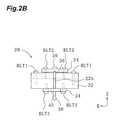
Fig. 2B is a front view of the positional displacement detector included in the robot hand. -
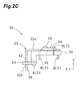
Fig. 2C is a side view of the positional displacement detector included in the robot hand. -
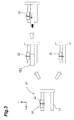
Fig. 3 is a diagram for describing an operation of the robot hand. -
Fig. 4A is a flowchart of an operation of a robot system including the robot hand. -
Fig. 4B is a flowchart of an operation of the robot system before gripping of an object by the robot hand. -
Fig. 4C is a flowchart of an operation of the robot system after the gripping of the object by the robot hand. -
Fig. 5 is a waveform chart of a signal output by a vibration detector when the robot hand verifies the gripping of the object. -
Fig. 6 is a waveform chart of a signal output by the vibration detector when a positional displacement of the object gripped by the robot hand has occurred. -
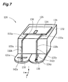
Fig. 7 is a perspective view of a positional displacement detector of a robot hand according to a second embodiment of the invention. - Embodiments of this invention will now be described with reference to the drawings to facilitate understanding of the invention. Components unrelated to the description may not be illustrated in the drawings.
- An XYZ coordinate system is defined in
Fig. 1 for convenience of the description. The XYZ coordinate system is composed of an X axis extending in one direction, a Y axis extending in a direction intersecting the X axis, and a Z axis extending in a direction intersecting the X axis and the Y axis. This XYZ coordinate system may be a rectangular coordinate system. - A
robot hand 10 according to a first embodiment of the invention is provided, for example, at an end portion of arobot arm 12 as illustrated inFig. 1 . - The
robot hand 10 includes abase 13 and a pair ofgripping claws 14 extending from thebase 13 in an X axis direction. An object to be gripped by therobot hand 10 is gripped by the pair of grippingclaws 14, which open and close in a Z axis direction. - The
robot hand 10 also includes apositional displacement detector 20 provided on a side face of one of thegripping claws 14. - The
positional displacement detector 20 includes acontact member 22, aprohibition member 24, and avibration detector 26 as illustrated inFigs. 2A to 2C . - The
contact member 22 is capable of making contact with the object gripped by the grippingclaws 14. Thecontact member 22 has a shape of a rod-like component bent at a midpoint and has elasticity. The contact member may be configured with, for example, metal or resin. - To describe in detail, the
contact member 22 includes afixation portion 22a extending in a Y-axis positive direction (a first direction) and acontact portion 22b extending from an end portion of thefixation portion 22a in a Z-axis negative direction (a second direction). - The
fixation portion 22a of thecontact member 22 is fixed to the side face of the grippingclaw 14 with bolts BLT1. A support member (an example of a member to be fixed) 32, which is an angle member, is disposed between thefixation portion 22a and the side face of thegripping claw 14. Thefixation portion 22a is interposed between thesupport member 32 and a plate-like fixation member 34. Thefixation member 34 is fastened to thesupport member 32 with bolts BLT2 to fix thefixation portion 22a. Thefixation member 34 has agroove 36 on its surface facing thefixation portion 22a to allow thefixation portion 22a to fit in thegroove 36. Thegroove 36 extends in a Y axis direction. Thus, with the bolts BLT2 fixing thefixation member 34 loosened, thecontact member 22 can be shifted along thegroove 36 in the Y axis direction. - An end portion of the
contact portion 22b of thecontact member 22 is capable of making contact with the object gripped by the grippingclaws 14. Afriction member 38 having a higher coefficient of friction than the object is provided at the end portion of thecontact portion 22b. Thisfriction member 38 may be, for example, rubber in the case of an object being a metallic workpiece. - The
prohibition member 24 is capable of making contact with thecontact member 22 and thereby prohibiting a deformation of a magnitude equal to or more than a predetermined magnitude from being caused to thecontact member 22. Theprohibition member 24 is fixed to thesupport member 32 with bolts BLT3. Theprohibition member 24 has ahole 42 with a central axis along the Z axis direction. Thecontact portion 22b of thecontact member 22 passes through thehole 42 at a central portion of thehole 42. - The
hole 42 has a diameter of a size corresponding to a tolerable positional displacement quantity to be set for an object. For example, to tolerate a positional displacement of 3 mm, the radius of thehole 42 is set to 3 mm. - The tolerable positional displacement quantity can be changed by making a plurality of prohibition members with the
holes 42 having different diameters available for replacement. Provision of a mechanism for adjusting the diameter of thehole 42 is also viable in place of the making available of the plurality of prohibition members with theholes 42 having different diameters. - Note that the
hole 42 formed in theprohibition member 24 may be a notch as long as the notch can prohibit a deformation of thecontact member 22. - The
vibration detector 26 is capable of detecting a vibration of thecontact member 22 and theprohibition member 24. Thevibration detector 26 has, for example, electric resistance varying with vibration detected. - The
vibration detector 26 is provided, for example, on a surface opposite to the fixed surface of thefixation member 34. For the ease of detection of a vibration, thevibration detector 26 is desirably provided on this surface, especially over thefixation portion 22a of thecontact member 22 and toward the Y-axis positive direction. In other words, thevibration detector 26 is provided desirably on thefixation member 34 near thecontact portion 22b. - The
contact member 22 may be partially enlarged to have a widened portion, so that thevibration detector 26 is provided on the widened portion instead of thefixation member 34. - The
vibration detector 26 may be configured with, for example, a strain gauge (an example of a strain detection sensor), which detects a strain caused by a vibration in the form of a change in electric resistance. - The change in electric resistance of the
vibration detector 26 is converted to a change in voltage by anamplifier substrate 52 illustrated inFig. 1 . The change in voltage is subjected to conversion from an analog signal to a digital signal by an A/D board 56, which is an A/D converter, connected to amicrocomputer 54. The digital signal is input into aprocessor 60, which processes data. Thisprocessor 60 is achieved by software executed by themicrocomputer 54. - The processor may be construed as part of the positional displacement detector.
- A
robot system 64 is configured with at least therobot hand 10 and theprocessor 60. - An operation of the
robot hand 10 and positional displacement detection processing (an operation of the robot system 64) associated with the operation of therobot hand 10 will now be described. - When a control device, not shown, that controls the
robot hand 10 outputs a command (a closing command) to close the grippingclaws 14, therobot hand 10 enables the pair ofgripping claws 14 to grip an object OBJ as illustrated at an upper level inFig. 3 . If a slip occurring during the gripping causes, to the object OBJ, a positional displacement equal to or more than a tolerable positional displacement quantity that is tolerated, thecontact member 22 moves (deforms) to make contact with theprohibition member 24, allowing the positional displacement to be detected and prompting the processor 60 (seeFig. 1 ) to output a positional displacement detection signal. - If, after the outputting of the closing command, the
robot hand 10 fails to grip the object OBJ as illustrated at a lower level inFig. 3 , the failure in the gripping of the object OBJ is detected, prompting theprocessor 60 to output a grip error signal. - As illustrated in
Fig. 4A , after the outputting of the closing command to close the grippingclaws 14, theprocessor 60 executes grip verification processing S1 to verify whether the object has been griped. Subsequently, theprocessor 60 executes positional displacement detection processing S2 to detect the positional displacement after the gripping of the object. - In the grip verification processing S1, the
processor 60 executes processing as described below and illustrated inFig. 4B . - The
processor 60 acquires a voltage value V based on an electric resistance value of thevibration detector 26 via the A/D board 56. - As illustrated in
Fig. 5 , upon the making contact of thecontact member 22 with the object, thecontact member 22 deforms to cause a change in electric resistance of thevibration detector 26, increasing the voltage value V (see B1 illustrated inFig. 5 ). If the voltage value V becomes equal to or more than a threshold Vthr1 (see B2 illustrated inFig. 5 ), it can be determined that the grippingclaws 14 have gripped the object. Note that the threshold Vthr1 is set to such a magnitude that a minute deformation caused to thecontact member 22 due to inertia of the opening and closing of the grippingclaws 14 is not detected. - If the voltage value V is equal to or more than the threshold Vthr1, the
processor 60 determines that thecontact member 22 has made contact with the object and has deformed. This is followed by the execution of step S1-3. - If the voltage value V is less than the threshold Vthr1, the
processor 60 determines that thecontact member 22 is not in contact with the object. This is followed by the execution of step S1-4. - The
processor 60 outputs a grip verification signal on the basis of the determination that the object has been gripped. Then, the grip verification processing S1 is finished. - The flowchart proceeds to return to step S1-1 until a predetermined time T1 (second) elapses after the outputting of the closing command to close the gripping
claws 14 of therobot hand 10. In other words, step S1-1 and step S1-2 are repeated until the elapse of the time T1 (second). - The flowchart proceeds to step S1-5 if the time T1 (second) has elapsed after the outputting of the command to close the gripping
claws 14 of therobot hand 10. - The
processor 60 outputs a grip error signal indicative of a failure in the gripping of the object. Then, the grip verification processing S1 is finished. - Upon the outputting of the grip error signal, the
robot hand 10 is allowed to stop the operation to hold the object and inform an on-site operator of the failure in the gripping of the object. - Subsequently, in the positional displacement detection processing S2, the
processor 60 executes processing described below and illustrated inFig. 4C . - The
processor 60 acquires a voltage value V based on an electric resistance value of thevibration detector 26 via the A/D board 56. - The
processor 60 performs low-pass filter processing on the voltage value V to obtain a voltage value Vflt. - The
processor 60 performs differentiation processing on the voltage value Vflt to obtain a voltage differential value Vdif. - As illustrated in
Fig. 6 , upon the start of the positional displacement of the object, thecontact member 22 in contact with the object deforms to vibrate with the positional displacement of the object. The vibration generated manifests itself in the form of a change in electric resistance of thevibration detector 26, and the voltage differential value Vdif increases with the change in electric resistance (see C1 illustrated inFig. 6 ). If the positional displacement of the object exceeds the tolerable positional displacement quantity, thecontact portion 22b of thecontact member 22 makes contact with theprohibition member 24, producing an impact. This reverses the increase/decrease of the voltage differential value Vdif (see C2 illustrated inFig. 6 ). Within T2 (second) after the sign of the voltage differential value Vdif is reversed (see C3 illustrated inFig. 6 ), the absolute value of the voltage differential value Vdif becomes equal to or more than a threshold Vthr2 (see C4 illustrated inFig. 6 ), allowing determination of the positional displacement of the object. - Here, the
processor 60 determines that thecontact member 22 has made contact with theprohibition member 24 and that the positional displacement of the object equal to or more than the tolerable positional displacement quantity has occurred if two conditions A and B described below are satisfied. - The absolute value |Vdif| of the voltage differential value Vdif is equal to or more than the threshold Vthr2 that has been preset.
- The reversal of the sign of the voltage differential value Vdif has been detected in T2 (second) (a predetermined duration) before the condition A is satisfied.
- This is followed by the execution of step S2-5.
- If at least one of the two conditions A and B is not satisfied, the
processor 60 determines that the quantity of the positional displacement of the object is within the tolerable positional displacement quantity, and the flowchart reverts to step S2-1. - The
processor 60 outputs the positional displacement detection signal. - Upon the outputting of the positional displacement detection signal, the
robot hand 10 puts the object being gripped to another location temporarily and starts the gripping operation on a succeeding object to be gripped. Here, an action against another positional displacement can be taken by increasing a gripping force. - According to this embodiment, an object's positional displacement equal to or more than a tolerable positional displacement quantity can be detected as described above.
- Note that it is feasible to retrofit the
positional displacement detector 20 on an existing gripping claw including nopositional displacement detector 20. - A robot hand according to a second embodiment of the invention will now be described. Identical reference figures are used to indicate components identical to those of the
robot hand 10 according to the first embodiment, and a description thereof in detail is omitted. - The robot hand according to the second embodiment includes a
positional displacement detector 120. - As illustrated in
Fig. 7 , thepositional displacement detector 120 includes anX-axis contact member 122x and a Y-axis contact member 122y, anX-axis prohibition member 124x and a Y-axis prohibition member 124y, and avibration detector 126. - The
contact members claws 14. Thecontact members contact members contact members fixation portion 122a extending in the Y-axis positive direction (the first direction) and acontact portion 122b extending from an end portion of thefixation portion 122a in the Z-axis negative direction (the second direction). - The
fixation portion 122a of each of thecontact members gripping claw 14 with a bolt. A support member (an example of a member to be fixed) 132, which is an angle member, is disposed between thefixation portions 122a and the side surface of thegripping claw 14. Thefixation portions 122a are interposed between thesupport member 132 and a plate-like fixation member 134. Thefixation member 134 is fastened to thesupport member 132 with a bolt (not shown) to fix thefixation portions 122a. Thefixation member 134 hasgrooves 136 on its surface facing thefixation portions 122a to allow thefixation portions 122a to fit in thegrooves 136. Thus, with the bolt loosened, thecontact members grooves 136 in the Y axis direction. - End portions of the
contact portions 122b of thecontact members claws 14.Friction members 138 having higher coefficients of friction than the object are provided at the end portions of thecontact portions 122b. - The
X-axis prohibition member 124x and the Y-axis prohibition member 124y, which are spaced from each other in the X axis direction, are individually fixed to thesupport member 132. - The
X-axis prohibition member 124x has arectangular hole 142x with a longer length in the X axis direction. Thecontact portion 122b of theX-axis contact member 122x passes through thehole 142x at a central portion of thehole 142x. - The Y-
axis prohibition member 124y has arectangular hole 142y with a longer length in the Y axis direction. Thecontact portion 122b of the Y-axis contact member 122y passes through thehole 142y at a central portion of thehole 142y. - The lengths of the
holes holes - The tolerable positional displacement quantities can be changed by making a plurality of prohibition members with the
holes - The widths of the
holes contact members holes contact members - The
vibration detector 126 is capable of detecting vibrations of theX-axis contact member 122x and theX-axis prohibition member 124x and vibrations of the Y-axis contact member 122y and the Y-axis prohibition member 124y. - The
positional displacement detector 120 according to this embodiment includes theX-axis contact member 122x and theX-axis prohibition member 124x, and the Y-axis contact member 122y and the Y-axis prohibition member 124y, allowing the positional displacements of the object in the X axis direction and in the Y axis direction to be detected. - Note that the
support member 132 may include an X-axis vibration detector to detect a vibration in the X axis direction and a Y-axis vibration detector to detect a vibration in the Y axis direction. - The invention is in no way limited to the embodiments described above and can be modified without changing the spirit of the invention. For example, a combination of the embodiments described above and modifications thereof in whole or in part is included in the technical scope of the invention.
- For example, it is feasible to provide a processor in a robot control device that controls a robot hand to detect a positional displacement in the embodiments described above. In this case, an A/D board can be connected to a PCI bus or the like of the robot control device.
- A vibration detector may output, for example, a voltage on the basis of a vibration detected. In the case of the vibration detector outputting a voltage, an amplifier substrate amplifies the voltage for outputting. The vibration detector may be any detector that detects some type of change in response to a vibration.
- Additionally, a vibration detector may be configured with another type of strain detection sensor, such as a piezoelectric element. A sensor capable of detecting a vibration of a contact member or the magnitude of an impact may be used as a vibration detector.
- Although the vibration detector detects the making contact between the contact member and the prohibition member in the embodiments described above, any means capable of detecting the making contact between the contact member and the prohibition member may be used. For example, a contact may be configured with a contact member having electrical conductivity and a prohibition member having electrical conductivity. The making contact between the contact member and the prohibition member (the occurrence of a positional displacement of an object) may be detected when this contact is closed.
- A contact portion of a contact member may be arranged to pass through a hole formed in a gripping claw at its central portion in the Y axis direction when observed in a plan view in the Z axis direction, so that the contact portion makes contact with an object at the central portion of the gripping claw in the Y axis direction.
- 10: robot hand, 12: robot arm, 13: base, 14: gripping claw, 20: positional displacement detector, 22: contact member, 22a: fixation portion, 22b: contact portion, 24: prohibition member, 26: vibration detector, 32: support member, 34: fixation member, 36: groove, 38: friction member, 42: hole, 52: amplifier substrate, 54: microcomputer, 56: A/D board, 60: processor, 64: robot system, 120: positional displacement detector, 122a: fixation portion, 122b: contact portion, 122x: X-axis contact member, 122y: Y-axis contact member, 124x: X-axis prohibition member, 124y: Y-axis prohibition member, 126: vibration detector, 132: support member, 134: fixation member, 136: groove, 138: motion member, 142x: hole, 142y: hole, OBJ: object, BLT1, BLT2, BLT3 : bolt
Claims (15)
- A positional displacement detector, comprising:a contact member configured to make contact with an object and deform with a positional displacement of the object;a prohibition member configured to make contact with the deformed contact member to prohibit a deformation of a magnitude equal to or more than a predetermined magnitude from being caused to the contact member; anda vibration detector configured to detect a vibration generated when the contact member has made contact with the prohibition member.
- The positional displacement detector according to claim 1, wherein the prohibition member has a hole or a notch through which the contact member passes.
- The positional displacement detector according to claim 2, wherein the contact member includes at its end portion a friction member configured to make contact with the object and having a higher coefficient of friction than the object.
- The positional displacement detector according to claim 3, further comprising a fixation member configured to fix the contact member interposed between the fixation member and a member to be fixed,
wherein the vibration detector is configured with a strain detection sensor provided on the fixation member. - The positional displacement detector according to claim 4, wherein the strain detection sensor is a strain gauge.
- The positional displacement detector according to claim 5, further comprising a processor configured to receive a voltage differential value yielded by differentiation of a voltage value obtained from the strain gauge,
wherein the processor determines that the positional displacement has occurred when a condition A and a condition B are both satisfied, the condition A being that an absolute value of the voltage differential value is equal to or more than a preset threshold, the condition B being that a reversal of a sign of the voltage differential value has been detected in a predetermined duration before the condition A is satisfied. - The positional displacement detector according to any one of claims 1 to 3,
wherein the contact member and the prohibition member each have electrical conductivity, and
a contact configured with the contact member and the prohibition member is included in place of the vibration detector. - A robot hand, comprising:gripping claws configured to grip an object;a contact member configured to make contact with the object gripped by the gripping claws and deform with a positional displacement of the object;a prohibition member configured to make contact with the deformed contact member to prohibit a deformation of a magnitude equal to or more than a predetermined magnitude from being caused to the contact member; anda vibration detector configured to detect a vibration generated when the contact member has made contact with the prohibition member.
- The robot hand according to claim 8,
wherein the contact member includes a fixation portion and a contact portion,
the fixation portion extending in a first direction and being fixed to the gripping claws,
the contact portion extending from the fixation portion in a second direction intersecting the first direction, the contact portion being configured to make contact with the object. - The robot hand according to claim 9, wherein the prohibition member has a hole or a notch through which the contact portion of the contact member passes.
- The robot hand according to claim 10, further comprising a fixation member configured to fix the fixation portion of the contact member, the fixation portion being interposed between the fixation member and the gripping claws,
wherein the fixation member has a groove in which the fixation portion fits, the groove extending in the first direction. - The robot hand according to claim 11, wherein the vibration detector is configured with a strain detection sensor provided on the fixation member.
- The robot hand according to any one of claims 8 to 11, wherein the contact member and the prohibition member each have electrical conductivity, and
a contact configured with the contact member and the prohibition member is included in place of the vibration detector. - A robot system, comprising a robot hand and a processor,
the robot hand including:gripping claws configured to grip an object;a contact member configured to make contact with the object gripped by the gripping claws and deform with a positional displacement of the object;a prohibition member configured to make contact with the deformed contact member to prohibit a deformation of a magnitude equal to or more than a predetermined magnitude from being caused to the contact member; anda vibration detector configured to detect a vibration generated when the contact member has made contact with the prohibition member,the processor being configured to determine that the gripping of the object by the gripping claws has failed when a signal based on the vibration detected by the vibration detector does not become equal to or more than a predetermined magnitude before a predetermined time elapses after a command to close the gripping claws is output. - The robot system according to claim 14, wherein the vibration detector is configured with a strain detection sensor, the strain detection sensor being configured to output a signal based on a strain caused by the vibration, and
the processor is configured to receive a voltage differential value yielded by differentiation of a voltage value obtained from the signal output by the strain detection sensor, the processor being configured to determine that the positional displacement has occurred when a condition A and condition B are both satisfied, the condition A being that an absolute value of the voltage differential value is equal to or more than a preset threshold, the condition B being that a sign of the voltage differential value has been reversed in a predetermined duration before the condition A is satisfied.
Applications Claiming Priority (1)
| Application Number | Priority Date | Filing Date | Title |
|---|---|---|---|
| PCT/JP2011/067791 WO2013018213A1 (en) | 2011-08-03 | 2011-08-03 | Positional displacement detector, robot hand, and robot system |
Publications (2)
| Publication Number | Publication Date |
|---|---|
| EP2741065A1 true EP2741065A1 (en) | 2014-06-11 |
| EP2741065A4 EP2741065A4 (en) | 2015-06-03 |
Family
ID=47628775
Family Applications (1)
| Application Number | Title | Priority Date | Filing Date |
|---|---|---|---|
| EP11870313.1A Withdrawn EP2741065A4 (en) | 2011-08-03 | 2011-08-03 | POSITIONAL DISPLACEMENT DETECTOR, HAND OF ROBOT AND ROBOT SYSTEM |
Country Status (4)
| Country | Link |
|---|---|
| US (1) | US20140145458A1 (en) |
| EP (1) | EP2741065A4 (en) |
| CN (1) | CN103814281A (en) |
| WO (1) | WO2013018213A1 (en) |
Cited By (1)
| Publication number | Priority date | Publication date | Assignee | Title |
|---|---|---|---|---|
| EP3552777A1 (en) * | 2018-04-11 | 2019-10-16 | TRUMPF Maschinen Austria GmbH & Co. KG. | Method for controlling the motion of a manipulator holding a workpiece |
Families Citing this family (6)
| Publication number | Priority date | Publication date | Assignee | Title |
|---|---|---|---|---|
| DE102014017855A1 (en) * | 2014-12-03 | 2016-06-09 | Dürr Systems GmbH | Handling device for opening a flap and corresponding method |
| ES2822926T3 (en) * | 2016-03-17 | 2021-05-05 | Siemens Healthcare Diagnostics Products Gmbh | Procedure for monitoring the transport of liquid containers in an automatic analysis device |
| CN105880904B (en) * | 2016-04-11 | 2017-09-19 | 浙江陆虎汽车有限公司 | Roof bow mistake proofing is oriented to testing agency |
| CN105945999A (en) * | 2016-06-01 | 2016-09-21 | 淮南市鸿裕工业产品设计有限公司 | Contact induction control module of grabbing device |
| DE102019129417B4 (en) * | 2019-10-31 | 2022-03-24 | Sick Ag | Methods for automatically manipulating objects |
| JP7446581B2 (en) * | 2019-12-10 | 2024-03-11 | 国立大学法人 名古屋工業大学 | Robot hand equipped with a vibration sensor and robot system equipped with the same |
Family Cites Families (13)
| Publication number | Priority date | Publication date | Assignee | Title |
|---|---|---|---|---|
| JPS4853464A (en) * | 1971-11-04 | 1973-07-27 | ||
| JPS536890A (en) * | 1976-07-09 | 1978-01-21 | Hitachi Ltd | Contact sensor |
| EP0173234A1 (en) * | 1984-08-24 | 1986-03-05 | The Perkin-Elmer Corporation | Robotic grip assembly |
| JPS6156891A (en) | 1984-08-24 | 1986-03-22 | 日本電信電話株式会社 | Sliding sense sensor |
| JPS6259886A (en) * | 1985-09-11 | 1987-03-16 | Fuji Facom Corp | Contact detecting device for moving body |
| JPS63117242A (en) * | 1986-11-04 | 1988-05-21 | Koyo Seiko Co Ltd | Gripping condition detector for robot |
| JP2728182B2 (en) * | 1990-10-30 | 1998-03-18 | キヤノン株式会社 | Work holding device |
| GB9204592D0 (en) * | 1992-03-03 | 1992-04-15 | The Technology Partnership Plc | Movement detector using mechanical vibrations |
| US5616590A (en) * | 1994-06-30 | 1997-04-01 | Ciba-Geigy Corporation | Plant microbicides |
| JP3652444B2 (en) * | 1996-06-19 | 2005-05-25 | 本田技研工業株式会社 | Stress measuring device |
| DE102006057881C5 (en) * | 2006-12-08 | 2010-07-22 | Norma Germany Gmbh | Tensionable clamp |
| WO2009144767A1 (en) * | 2008-05-29 | 2009-12-03 | 株式会社ハーモニック・ドライブ・システムズ | Complex sensor and robot hand |
| JP2010149262A (en) * | 2008-12-26 | 2010-07-08 | Nihon Univ | Robot hand system with gripping part |
-
2011
- 2011-08-03 EP EP11870313.1A patent/EP2741065A4/en not_active Withdrawn
- 2011-08-03 CN CN201180073382.5A patent/CN103814281A/en active Pending
- 2011-08-03 WO PCT/JP2011/067791 patent/WO2013018213A1/en not_active Ceased
-
2014
- 2014-01-31 US US14/169,153 patent/US20140145458A1/en not_active Abandoned
Cited By (1)
| Publication number | Priority date | Publication date | Assignee | Title |
|---|---|---|---|---|
| EP3552777A1 (en) * | 2018-04-11 | 2019-10-16 | TRUMPF Maschinen Austria GmbH & Co. KG. | Method for controlling the motion of a manipulator holding a workpiece |
Also Published As
| Publication number | Publication date |
|---|---|
| CN103814281A (en) | 2014-05-21 |
| US20140145458A1 (en) | 2014-05-29 |
| EP2741065A4 (en) | 2015-06-03 |
| WO2013018213A1 (en) | 2013-02-07 |
Similar Documents
| Publication | Publication Date | Title |
|---|---|---|
| US20140145458A1 (en) | Positional displacement detector, robot hand, and robot system | |
| CA2996698C (en) | Systems and methods for providing contact detection in an articulated arm | |
| JP6988757B2 (en) | End effector and end effector device | |
| JP4977825B2 (en) | Shear force detection device and object gripping system | |
| US9909852B2 (en) | Operation position detection apparatus and vehicular apparatus | |
| WO2020194393A1 (en) | Robot hand, robot hand control method, and program | |
| US11931887B2 (en) | End effector device | |
| US8516891B2 (en) | Multi-stage stopper system for MEMS devices | |
| JP2019023639A5 (en) | ||
| JP5215331B2 (en) | Work determination system, work determination method, and recording medium recording the work determination method | |
| US12287248B2 (en) | Piezoelectric sensor and robot hand | |
| JPWO2013018213A1 (en) | Misalignment detector, robot hand and robot system | |
| JP5884456B2 (en) | Intervening sensor and robot | |
| CN210791052U (en) | An anti-collision device for robot collision detection | |
| CN106932123B (en) | A kind of wrist sensor | |
| CN113043071B (en) | Force sensing device capable of sensing low frequency force and high frequency force | |
| JP5874435B2 (en) | Vehicle input device | |
| KR20110136036A (en) | Robot teaching device and method | |
| US20120055268A1 (en) | Manipulated position detection device | |
| WO2023065102A1 (en) | Gripper and robot having the same | |
| CN206510862U (en) | A kind of ECU fixing devices | |
| JP2023051285A (en) | force sensor | |
| CN110539335A (en) | A buffer stop for robot collision detection | |
| Petchartee et al. | Pre-slip detection based Tactile Sensing | |
| US20220227011A1 (en) | Tactile Sensor, Robot Hand, and Robot |
Legal Events
| Date | Code | Title | Description |
|---|---|---|---|
| PUAI | Public reference made under article 153(3) epc to a published international application that has entered the european phase |
Free format text: ORIGINAL CODE: 0009012 |
|
| 17P | Request for examination filed |
Effective date: 20140226 |
|
| AK | Designated contracting states |
Kind code of ref document: A1 Designated state(s): AL AT BE BG CH CY CZ DE DK EE ES FI FR GB GR HR HU IE IS IT LI LT LU LV MC MK MT NL NO PL PT RO RS SE SI SK SM TR |
|
| DAX | Request for extension of the european patent (deleted) | ||
| RA4 | Supplementary search report drawn up and despatched (corrected) |
Effective date: 20150508 |
|
| RIC1 | Information provided on ipc code assigned before grant |
Ipc: B25J 13/08 20060101ALI20150429BHEP Ipc: G01L 5/00 20060101AFI20150429BHEP Ipc: B25J 15/08 20060101ALI20150429BHEP |
|
| STAA | Information on the status of an ep patent application or granted ep patent |
Free format text: STATUS: THE APPLICATION IS DEEMED TO BE WITHDRAWN |
|
| 18D | Application deemed to be withdrawn |
Effective date: 20151208 |