EP2740824B1 - Triaxial textile armature, process for producing triaxial textile armatures and composite material part - Google Patents
Triaxial textile armature, process for producing triaxial textile armatures and composite material part Download PDFInfo
- Publication number
- EP2740824B1 EP2740824B1 EP12196166.8A EP12196166A EP2740824B1 EP 2740824 B1 EP2740824 B1 EP 2740824B1 EP 12196166 A EP12196166 A EP 12196166A EP 2740824 B1 EP2740824 B1 EP 2740824B1
- Authority
- EP
- European Patent Office
- Prior art keywords
- yarns
- axial
- wheels
- axial yarns
- bias
- Prior art date
- Legal status (The legal status is an assumption and is not a legal conclusion. Google has not performed a legal analysis and makes no representation as to the accuracy of the status listed.)
- Active
Links
- 238000000034 method Methods 0.000 title claims description 29
- 230000008569 process Effects 0.000 title claims description 29
- 239000004753 textile Substances 0.000 title claims description 19
- 239000002131 composite material Substances 0.000 title claims description 16
- 238000009954 braiding Methods 0.000 claims description 64
- 239000000969 carrier Substances 0.000 claims description 23
- 230000002787 reinforcement Effects 0.000 claims description 3
- 239000000463 material Substances 0.000 claims 3
- 230000002093 peripheral effect Effects 0.000 claims 2
- 238000010276 construction Methods 0.000 claims 1
- 238000005728 strengthening Methods 0.000 claims 1
- 239000000725 suspension Substances 0.000 claims 1
- 239000000835 fiber Substances 0.000 description 27
- 239000004744 fabric Substances 0.000 description 11
- 238000004519 manufacturing process Methods 0.000 description 7
- 239000011347 resin Substances 0.000 description 4
- 229920005989 resin Polymers 0.000 description 4
- OKTJSMMVPCPJKN-UHFFFAOYSA-N Carbon Chemical compound [C] OKTJSMMVPCPJKN-UHFFFAOYSA-N 0.000 description 2
- 238000005452 bending Methods 0.000 description 2
- 230000015572 biosynthetic process Effects 0.000 description 2
- 229910052799 carbon Inorganic materials 0.000 description 2
- 230000003247 decreasing effect Effects 0.000 description 2
- 230000008021 deposition Effects 0.000 description 2
- 239000011159 matrix material Substances 0.000 description 2
- 230000007246 mechanism Effects 0.000 description 2
- 239000011800 void material Substances 0.000 description 2
- 230000000903 blocking effect Effects 0.000 description 1
- 230000008859 change Effects 0.000 description 1
- 238000005056 compaction Methods 0.000 description 1
- 230000007423 decrease Effects 0.000 description 1
- 239000006260 foam Substances 0.000 description 1
- 230000006872 improvement Effects 0.000 description 1
- 238000001802 infusion Methods 0.000 description 1
- 238000006116 polymerization reaction Methods 0.000 description 1
- 239000002994 raw material Substances 0.000 description 1
- 230000035939 shock Effects 0.000 description 1
- 239000003351 stiffener Substances 0.000 description 1
Images


Classifications
-
- D—TEXTILES; PAPER
- D04—BRAIDING; LACE-MAKING; KNITTING; TRIMMINGS; NON-WOVEN FABRICS
- D04C—BRAIDING OR MANUFACTURE OF LACE, INCLUDING BOBBIN-NET OR CARBONISED LACE; BRAIDING MACHINES; BRAID; LACE
- D04C1/00—Braid or lace, e.g. pillow-lace; Processes for the manufacture thereof
- D04C1/06—Braid or lace serving particular purposes
-
- D—TEXTILES; PAPER
- D04—BRAIDING; LACE-MAKING; KNITTING; TRIMMINGS; NON-WOVEN FABRICS
- D04C—BRAIDING OR MANUFACTURE OF LACE, INCLUDING BOBBIN-NET OR CARBONISED LACE; BRAIDING MACHINES; BRAID; LACE
- D04C3/00—Braiding or lacing machines
- D04C3/02—Braiding or lacing machines with spool carriers guided by track plates or by bobbin heads exclusively
- D04C3/20—Arrangement of bobbin heads and guides or track plates in the machine
-
- D—TEXTILES; PAPER
- D04—BRAIDING; LACE-MAKING; KNITTING; TRIMMINGS; NON-WOVEN FABRICS
- D04C—BRAIDING OR MANUFACTURE OF LACE, INCLUDING BOBBIN-NET OR CARBONISED LACE; BRAIDING MACHINES; BRAID; LACE
- D04C3/00—Braiding or lacing machines
- D04C3/02—Braiding or lacing machines with spool carriers guided by track plates or by bobbin heads exclusively
- D04C3/36—Frames
-
- D—TEXTILES; PAPER
- D04—BRAIDING; LACE-MAKING; KNITTING; TRIMMINGS; NON-WOVEN FABRICS
- D04C—BRAIDING OR MANUFACTURE OF LACE, INCLUDING BOBBIN-NET OR CARBONISED LACE; BRAIDING MACHINES; BRAID; LACE
- D04C3/00—Braiding or lacing machines
- D04C3/40—Braiding or lacing machines for making tubular braids by circulating strand supplies around braiding centre at equal distances
-
- D—TEXTILES; PAPER
- D10—INDEXING SCHEME ASSOCIATED WITH SUBLASSES OF SECTION D, RELATING TO TEXTILES
- D10B—INDEXING SCHEME ASSOCIATED WITH SUBLASSES OF SECTION D, RELATING TO TEXTILES
- D10B2403/00—Details of fabric structure established in the fabric forming process
- D10B2403/02—Cross-sectional features
- D10B2403/024—Fabric incorporating additional compounds
- D10B2403/0241—Fabric incorporating additional compounds enhancing mechanical properties
- D10B2403/02411—Fabric incorporating additional compounds enhancing mechanical properties with a single array of unbent yarn, e.g. unidirectional reinforcement fabrics
-
- D—TEXTILES; PAPER
- D10—INDEXING SCHEME ASSOCIATED WITH SUBLASSES OF SECTION D, RELATING TO TEXTILES
- D10B—INDEXING SCHEME ASSOCIATED WITH SUBLASSES OF SECTION D, RELATING TO TEXTILES
- D10B2403/00—Details of fabric structure established in the fabric forming process
- D10B2403/02—Cross-sectional features
- D10B2403/024—Fabric incorporating additional compounds
- D10B2403/0241—Fabric incorporating additional compounds enhancing mechanical properties
- D10B2403/02412—Fabric incorporating additional compounds enhancing mechanical properties including several arrays of unbent yarn, e.g. multiaxial fabrics
-
- D—TEXTILES; PAPER
- D10—INDEXING SCHEME ASSOCIATED WITH SUBLASSES OF SECTION D, RELATING TO TEXTILES
- D10B—INDEXING SCHEME ASSOCIATED WITH SUBLASSES OF SECTION D, RELATING TO TEXTILES
- D10B2505/00—Industrial
- D10B2505/02—Reinforcing materials; Prepregs
Definitions
- the present invention relates to the domain of composite materials that are constituted by a textile armature, or long fiber reinforcement, impregnated with a resin named matrix.
- That invention is a new type of armature and its manufacturing process that allows obtaining low cost parts with complex shapes, open or closed, with high mechanical performances (value).
- That invention is more precisely a new type of textile architecture that is a triaxial braid with a majority of the yarns in the longitudinal direction and a constant thickness. For obtaining from those braids high performance composite materials, it's necessary that the yarns in the three directions have minimal fiber crimp and create few internal voids by their crossing. That is the result achieved by that invention.
- the reason for that is the crossing of the bias yarns between two axial yarns.
- the invention resolves that problem because it allows manufacturing triaxial braids with a constant thickness and a majority of fiber in the axial direction while keeping all the other advantages of the braiding process that creates at high speed in-shape parts, by introducing in the center of the braiding machine a mandrel that is covered by the yarns. That way of making parts is often named overbraiding.
- That textile armature holds layers of axial yarns disposed in quincunxes and linked two by two by the bias yarns. The first axial layer is linked with the second layer by the bias yarns with one orientation while the second layer is linked with the third one by the bias yarns with the other orientation. That textile armature is well done but is not symmetrical into its thickness and that can create some deformation during the polymerization with shrinkage of the resin matrix.
- Our present invention comprises a high quality tri-axial textile armature, very useful to manufacture cheaply lengthy parts directly in shape, in order of remediating at a lack in the range of existing processes.
- An armature in accordance with this invention has three fiber orientations, the first one axial and the two others making a angle, by example +60° and -60°, with the axial direction, in which those bias yarns do not cross each other during getting through the layer of axial yarns, but get it through in their respective odd and even intervals.
- the +60° yarns pass through the axial yarn layer in each odd interval while the -60° yarn passes through it in each even interval.
- the axial yarns in the central layer can have a round or elliptic cross section but more preferably the cross section of the axial yarns has a flattened cross section.
- This flattened cross section is needed to create a layer that has a minimum thickness and a maximum strength.
- the size of the cross section of the axial yarns of the central layer in a direction basically perpendicular to the thickness is at least twice the size of the cross section in the same direction of the axial yarns of the side layer or the bias yarns. It is noted that all kinds of cross sections can be applied.
- the process to manufacture those armatures in accordance with this invention is a braiding process, that is to say a process that moves the yarn bobbins by the way of rotating adjacent wheels exchanging each other's their bobbin carriers.
- a braiding machine for making an armature in accordance with this invention has to be built with two circumferential rows of adjacent wheels and three rows of tubes for introducing the axial yarns.
- the tubes of the external and internal rows are situated at the center of the notched wheels, while the tubes of the central row are situated at or near the crossing of the diagonals linking the axes of fourth adjacent wheels.
- Those braiding machines can be built within two ways of disposing the rotating wheels. The first way is in disposing the two rows of wheels on a disk. The second way is in disposing the two rows of wheels inside a cylindrical or spherical ring. In the both cases the yarns are laid on a central mandrel after leaning on a fixed ring surrounding it.
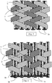
- the figure 1 is a view of a braid made in accordance with prior art. Inside that braid the axial yarns are separated by spaces equal or larger than their own width to allow the passing of the bias yarns through the axial yarns while there are crossing each other's into those same spaces.
- the composite material part obtained by laying many of such braids can't be a high quality part because each braided layer has not a constant thickness.
- the figure 2 is a schematic view of the disposition of the notched rotating wheels into a braiding machine made in the prior art for making armatures of composite material parts. That machine has only one row of notched wheels that are making by their rotations the bobbins carriers holding the bias yarns moving into opposite directions along two crossed paths. Those yarns are forming the braid around a central mandrel. The axial yarns are passing through the center of each notched wheel and are placed into the braid as shown on figure 1 .
- the figure 3 shows a first example of armature in accordance to the invention.
- the bias yarns 2 passes over two axial yarns 1a then passes under two axial yarns 1a.
- the bias yarns 3 also passes over and under two axial yarns 1a but their passing through the layer of yarns 1a are shifted of one interval with that of the bias yarns 2.
- this armature is characterized by the getting of the bias yarns 2, constituting a first direction, through the layer of axial yarns 1a in their intervals said even and the getting of the bias yarns 3, constituting the second direction, through that layer of axial yarns 1a in their intervals said odd.
- those axial yarn 1a intervals can be smaller than in the armature showed figure 1 because the bias yarns 2 and 3 get through the layer of yarns 1a in separated intervals and the yarns 2 never cross the yarns 3 in those intervals.
- the unit cell that characterizes this fibre architecture is made of one layer of four axial yarns linked by two sets of N crossed bias yarns, N being an even number, equal to two on this figure.
- the figure 4 shows a second example of armature in accordance with this invention.
- Axial yarns 1b were introduced over and under the intervals between the axial yarns 1a for improving the continuity of thickness of this armature.
- the unit cell that characterizes this fibre architecture is made by 12 axial yarns disposed on three layers, with the yarns 1a of the central layer in quincunxes with the yarns 1b of the side layers, linked by two crossed sets of N yarns, N being an even number, equal to two for the armature shown on this figure 3 .
- Each bias yarn 2 or 3 get over 6 and under 6 axial yarns 1a and 1b while crossing 2 ⁇ N yarns 3 or 2 of the other set of bias yarns.
- the created armature is suitable for making high performance composite material because its thickness is uniform and have a majority of the yarns in the axial direction.
- the armature shown on figure 4 has the sections of the yarns 1a of the central layer roughly two times bigger than the ones of yarns 1b of the side layers.
- its section can be usually chosen between two times and four times bigger than the section of the side axial yarns in order to improve the thickness homogeneity of that armature.
- the figure 5 shows a third example of the armature object of the invention.
- the N number of each set of bias yarns was doubled by comparison with the figure 4 , therefore it is equal to four. That allows having an armature in which the wideness of the bias yarns 2 or 3 is the same as the one of the side axial yarns 1b for an angle of 60°.
- the figure 5a shows a fourth example of the armature object of this invention.
- the N number of each set of bias yarns has been increased to six. That allows having an armature in which the width of the bias yarns 2 or 3 is the same that the one of the side axial yarns 1b for an angle of 45°.
- the figure 6 shows a section view of another example of armature in accordance with this invention in which a thick central layer is obtained by using as axial yarns 1a a light density product, by example a foam in order of creating an armature suitable for making the center part of a sandwich structure usable for impregnating by resin infusion.
- the bias yarns have in that armature the right positioning to carry the shear loads between the skins, the same positioning that we can find in the French patent Nb. 2.918.599 .
- the figure 7 shows a flat sketch of the disposition of the two rows of notched wheels 4 and of the three rows of tubes 5 and 6 in which are introduced the axial yarns 1a and 1b for making armatures in accordance with this invention.
- Each wheel has four notches as in any regular braiding machine.
- the tubes 5 in which the axial yarns 1b of the side layers are introduced are situated at the center of each notched wheel while the tubes 6 in which the axial yarns 1a of the central layer are introduced are situated near the crossing of the diagonals linking the axes of fourth adjacent wheels. All those wheels 4 are linked with gears 14 not shown on that sketch but visible on figure 10 .
- Each bobbin carrier 9 is guided by grooves 7 and 8 machined into a plate situated between the wheels and the gears.
- the bobbin carriers charged with the bias yarns 2 are moving to the right side guided by the grooves 7 while the bobbin carriers charged with the bias yarns 3 are moving to the left side guided by the grooves 8.
- Their guiding grooves are machined in such a way to allow the using of bobbins as big as possible as passing in the center between the tubes 5 and 6.
- the armature visible on figure 3 is obtained.
- the armatures visible on figure 4 or 5 are braided.
- their number is limited at two on each trajectory going from one wheel to the following four. Hence the armature visible on figure 5a is not doable by using wheels with four notches.
- the figure 7a shows the same sketch on which the number of notches on each wheels has been decreased to three.
- the number of bobbin carriers 9 can be increased to three on each trajectory without colliding. Hence the armature visible on figure 5a is doable by using wheels with only three notches.
- the figure 8 shows such a disposition of wheels on the internal row that have four notches, and wheels of the external row that have 5 notches. Hence it's possible to put three bobbin carriers on each trajectory of 9 notches.
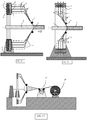
- the figure 9 shows a general front view of a braiding machine able to make the armature object of this invention. Its notched wheels are disposed on a vertical disk 13. That vertical disposition is usely named at horizontal axe. That disposition is convenient for intruding a mandrel 10 that will be covered by the yarns.
- the figure 10 is the side view of that braiding machine showing the gears 14 driving the wheels 4, the plate 15 in which the guiding grooves are machined. and the path of the yarns from the ends of the tubes 5 and 6 to the mandrel 10 on which they create the armature 12 after sliding inside the ring 11.
- the figure 11 shows the side view of a braiding machine made by disposing the two rows of wheels symmetrically inside a big ring.
- the surface on which the bobbin carriers move is a spherical surface.
- the figure 12 shows a braiding machine with its lower part installed into a pit for keeping the area of braid armature formation at a height convenient for the operators or for making easier the introduction of a great length mandrel into the center of that braiding machine.
- the created braid goes on a tensile apparatus 17 that makes the braid 12 moving at a constant speed and winds it on a drum 18.
- Those notched wheels are linked with gears 14 that are also in that ratio of 1.25 between their two rows.
- the diameter of the wheels of the internal row is 160 mm and the diameter of the ones of the external row is 200 mm. That machine can receive 84 bobbin carriers maximum.
- a mandrel 10 is situated in the machine center. Its shape can be the internal shape of the required part. So, its shape can be other than round, rectangular by example, have a variable size or a curvature to braid a fuselage frame by example. It can move to pull the braid or be fixed and the braid slides on it to be wounded around a drum (see figure 12 ).
- a cutting mechanism can be placed between the mandrel 10 and the drum 18 to wind on it a flat triaxial fabric.
- a ring 11 surrounds the mandrel 10 and help to facilitate the formation of the braided armature 12. It is linked at the machine frame 16 by some rods not shown here.
- the tuning of the mandrel speed, or of the sliding speed of the braid on it when the mandrel does not move, with the rotation speed of the wheels adjusts as required the angle of the bias yarns with the axial yarns.
- That braiding machine allows braiding an armature with three layers of 28 axial sites of yarns but, as we can put into the central layer two to four yarns, that braid has the equivalent of 112 to 168 axial yarns.
- the armature created by this braiding machine is similar at the one shown on the figure 5 .
- that braiding process produces triaxial armatures with the following features: with braiding a 45° braiding angle and a fiber volume ratio of 60%, a thickness of 1.5 mm, 59% of axial fibers and 41% of bias yarn, with a 60° braiding angle, a thickness of 1.7 mm , 50% of axial fibers and bias fibers.
- That triaxial armature will be produced at a rate of 320 Kg/hour for a 45° braiding angle, 220 Kg/hour for a 60° braiding angle.
- the internal wheel diameter is 200 mm and the external wheel diameter is 208.9 mm.
- the diameter of the bobbin carriers is 110 mm and the diameter of their bobbins is 80 mm.
- the external diameter of that braiding machine is 10 m. It will be useful to install it partially into a pit to facilitate the operator work.
- the braided armature will have the equivalent of 576 to 864 axial yarns depending of the number of yarns put in each tube of the central row.
- That braiding process produces triaxial armatures with the following features: with a 45° braiding angle, for a fiber volume ratio of 60%, a thickness of 1.52 mm, 59% of axial fibers and 41% of bias fibers, with a 60° braiding angle, a thickness of 1.78 mm, 50% of axial fibers and bias fibers. That triaxial armature will be produced at a rate of 1600 Kg/hour for a 45° braiding angle, 1100 Kg/hour for a 60° braiding angle.
- this new process will allow manufacturing in-shape reinforcement for composite parts, often named preforms, cheaper than any other process as all the yarns in three directions are wrapped together on the mandrel.
- the fiber laying rate is so much higher that it is a sure bet to use this new process.
- the price of the raw material is also cheaper as that process uses only dry fiber without all the troubles generated when using pre-impregnated yarns.
Description
- The present invention relates to the domain of composite materials that are constituted by a textile armature, or long fiber reinforcement, impregnated with a resin named matrix. That invention is a new type of armature and its manufacturing process that allows obtaining low cost parts with complex shapes, open or closed, with high mechanical performances (value). That invention is more precisely a new type of textile architecture that is a triaxial braid with a majority of the yarns in the longitudinal direction and a constant thickness. For obtaining from those braids high performance composite materials, it's necessary that the yarns in the three directions have minimal fiber crimp and create few internal voids by their crossing. That is the result achieved by that invention.
- We can give as an example of the prior art the fabric QISOTM from the A&P company. That triaxial fabric obtained by braiding on a regular braiding machine is said ISO as it has the same amount of fiber in the three directions, 0°, +60° and -60°. But the geometrical analysis shows that it's impossible to recover continuously the fabric surface at the same time by the oblique or bias yarns at + or - 60° and by the axial yarns at 0°.
- The reason for that is the crossing of the bias yarns between two axial yarns.
- The geometrical analysis of that crossing shows that if we want to cover all the surface by the bias yarns, without any void between two bias yarns, it is necessary to create a void between two axial yarns as big as their own width, that is to say that it is possible to recover only half part of the surface by the axial yarns. Hence, to have the same amount of fibers in the three directions, it's necessary to double the thickness of those axial yarns. The surface of such a fabric is made by alternate ribbons holding two layers of bias yarns and ribbons holding fourth layers, the two bias yarns and two axial yarns. Therefore that fiber architecture is not optimized and a part made by many layers of such a fabric will not have a fiber volume ratio high enough for making aeronautical parts. Such a fabric is manufactured on a regular braiding machine that produces textile architectures not good enough for making high performance composite materials.
- The invention resolves that problem because it allows manufacturing triaxial braids with a constant thickness and a majority of fiber in the axial direction while keeping all the other advantages of the braiding process that creates at high speed in-shape parts, by introducing in the center of the braiding machine a mandrel that is covered by the yarns. That way of making parts is often named overbraiding.
- A previous try to resolve that problem can be found in the French patent No.
2 753 993 of Georges CAHUZAC - Its manufacturing process consists in using a braiding machine that has notched wheels disposed in quincunxes inside a cylinder. The path of the moving bobbins holding the bias yarns is obtained by the combination of the rotation of those notched wheels with the changing of angle of guiding needles. That mechanism is complex and could block the functioning if not correctly tuned. The gears that are disposed in quincunxes under a cylinder are difficult to machine correctly. This braiding machine is expensive to build and uneasy to tune.
- Another example of prior art is given in the
French patent No 2 804 133 - That problem was solved in the English patent
GB 8234187 EP 0113196 in which is described a multilayer braiding machine that holds rows of tubes between the rows of notched wheels in order of inserting the axial yarns necessary to fill these voids. That machine has notched wheels that are not adjacent and are disposed on two different levels. The difference in rotational speed between each row allows the functioning of that machine only with few bobbin carriers, and with stops between two wheels. In reality, that braiding machine cannot work because there will be always a blocking step reached after some rotations. - Another example of prior art is given in the French patent No.
FR2884836 invented by Georges CAHUZAC - Our new textile armature for making composite material parts is based on using braiding machines with two rows of notched wheels known at least from the XIXth century since we can find a description of an improvement of such a machine in the
US patent No. 886825 of May 5th 1908 . A more recent example of such braiding machines can be found in the French patent No.1.105.915 of May 20th 1954 - Our present invention comprises a high quality tri-axial textile armature, very useful to manufacture cheaply lengthy parts directly in shape, in order of remediating at a lack in the range of existing processes. An armature in accordance with this invention has three fiber orientations, the first one axial and the two others making a angle, by example +60° and -60°, with the axial direction, in which those bias yarns do not cross each other during getting through the layer of axial yarns, but get it through in their respective odd and even intervals. The +60° yarns pass through the axial yarn layer in each odd interval while the -60° yarn passes through it in each even interval. The quality of those armatures is improved by adding little axial yarns on the upper and lower side of those intervals to obtain armatures with three layers of axial yarns, in which the central layer yarns are bigger than the side layer axial yarns. Those armatures have a remarkably constant thickness and all their yarns have very smooth paths.
- The axial yarns in the central layer can have a round or elliptic cross section but more preferably the cross section of the axial yarns has a flattened cross section. This flattened cross section is needed to create a layer that has a minimum thickness and a maximum strength. The size of the cross section of the axial yarns of the central layer in a direction basically perpendicular to the thickness is at least twice the size of the cross section in the same direction of the axial yarns of the side layer or the bias yarns. It is noted that all kinds of cross sections can be applied.
- The process to manufacture those armatures in accordance with this invention is a braiding process, that is to say a process that moves the yarn bobbins by the way of rotating adjacent wheels exchanging each other's their bobbin carriers.
- A braiding machine for making an armature in accordance with this invention has to be built with two circumferential rows of adjacent wheels and three rows of tubes for introducing the axial yarns. The tubes of the external and internal rows are situated at the center of the notched wheels, while the tubes of the central row are situated at or near the crossing of the diagonals linking the axes of fourth adjacent wheels. Those braiding machines can be built within two ways of disposing the rotating wheels. The first way is in disposing the two rows of wheels on a disk. The second way is in disposing the two rows of wheels inside a cylindrical or spherical ring. In the both cases the yarns are laid on a central mandrel after leaning on a fixed ring surrounding it.
- The annexed figures will help to better understand how this invention can be made.
- The
figure 1 is a view of a braid made in accordance with prior art. Inside that braid the axial yarns are separated by spaces equal or larger than their own width to allow the passing of the bias yarns through the axial yarns while there are crossing each other's into those same spaces. The composite material part obtained by laying many of such braids can't be a high quality part because each braided layer has not a constant thickness. - The
figure 2 is a schematic view of the disposition of the notched rotating wheels into a braiding machine made in the prior art for making armatures of composite material parts. That machine has only one row of notched wheels that are making by their rotations the bobbins carriers holding the bias yarns moving into opposite directions along two crossed paths. Those yarns are forming the braid around a central mandrel. The axial yarns are passing through the center of each notched wheel and are placed into the braid as shown onfigure 1 . - The
figure 3 shows a first example of armature in accordance to the invention. Thebias yarns 2 passes over two axial yarns 1a then passes under two axial yarns 1a. Thebias yarns 3 also passes over and under two axial yarns 1a but their passing through the layer of yarns 1a are shifted of one interval with that of thebias yarns 2. One can say that this armature is characterized by the getting of thebias yarns 2, constituting a first direction, through the layer of axial yarns 1a in their intervals said even and the getting of thebias yarns 3, constituting the second direction, through that layer of axial yarns 1a in their intervals said odd. - In this armature, those axial yarn 1a intervals can be smaller than in the armature showed
figure 1 because thebias yarns yarns 2 never cross theyarns 3 in those intervals. The unit cell that characterizes this fibre architecture is made of one layer of four axial yarns linked by two sets of N crossed bias yarns, N being an even number, equal to two on this figure. - The
figure 4 shows a second example of armature in accordance with this invention.Axial yarns 1b were introduced over and under the intervals between the axial yarns 1a for improving the continuity of thickness of this armature. The unit cell that characterizes this fibre architecture is made by 12 axial yarns disposed on three layers, with the yarns 1a of the central layer in quincunxes with theyarns 1b of the side layers, linked by two crossed sets of N yarns, N being an even number, equal to two for the armature shown on thisfigure 3 . Eachbias yarn axial yarns 1a and 1b while crossing 2∗N yarns figure 4 has the sections of the yarns 1a of the central layer roughly two times bigger than the ones ofyarns 1b of the side layers. As the place for each central axial yarn is two times larger and two times thicker than the one of the side axial yarn, its section can be usually chosen between two times and four times bigger than the section of the side axial yarns in order to improve the thickness homogeneity of that armature. - The
figure 5 shows a third example of the armature object of the invention. The N number of each set of bias yarns was doubled by comparison with thefigure 4 , therefore it is equal to four. That allows having an armature in which the wideness of thebias yarns axial yarns 1b for an angle of 60°. - The
figure 5a shows a fourth example of the armature object of this invention. The N number of each set of bias yarns has been increased to six. That allows having an armature in which the width of thebias yarns axial yarns 1b for an angle of 45°. - The
figure 6 shows a section view of another example of armature in accordance with this invention in which a thick central layer is obtained by using as axial yarns 1a a light density product, by example a foam in order of creating an armature suitable for making the center part of a sandwich structure usable for impregnating by resin infusion. The bias yarns have in that armature the right positioning to carry the shear loads between the skins, the same positioning that we can find in the French patent Nb.2.918.599 - The
figure 7 shows a flat sketch of the disposition of the two rows of notchedwheels 4 and of the three rows oftubes axial yarns 1a and 1b for making armatures in accordance with this invention. Each wheel has four notches as in any regular braiding machine. Thetubes 5 in which theaxial yarns 1b of the side layers are introduced are situated at the center of each notched wheel while thetubes 6 in which the axial yarns 1a of the central layer are introduced are situated near the crossing of the diagonals linking the axes of fourth adjacent wheels. All thosewheels 4 are linked withgears 14 not shown on that sketch but visible onfigure 10 . Eachbobbin carrier 9 is guided bygrooves 7 and 8 machined into a plate situated between the wheels and the gears. When all the wheels are rotating, the bobbin carriers charged with thebias yarns 2 are moving to the right side guided by thegrooves 7 while the bobbin carriers charged with thebias yarns 3 are moving to the left side guided by the grooves 8. Their guiding grooves are machined in such a way to allow the using of bobbins as big as possible as passing in the center between thetubes tubes 6, the armature visible onfigure 3 is obtained. By introducing yarns into the three rows of tubes, the armatures visible onfigure 4 or5 are braided. For avoiding that the bobbin carriers collide during braiding, their number is limited at two on each trajectory going from one wheel to the following four. Hence the armature visible onfigure 5a is not doable by using wheels with four notches. - The
figure 7a shows the same sketch on which the number of notches on each wheels has been decreased to three. The number ofbobbin carriers 9 can be increased to three on each trajectory without colliding. Hence the armature visible onfigure 5a is doable by using wheels with only three notches. - It's interesting to note that when the number of notches is even on the two rows of wheels, it's possible to put only two bobbin carriers on each trajectory of eight notches. When the number of notches of the wheels is odd on the two rows, it's possible to put a bobbin carriers each two notches. And when the number of notches is odd on a row and even on the other one, it's possible to put a bobbin carrier each three notches.
- The
figure 8 shows such a disposition of wheels on the internal row that have four notches, and wheels of the external row that have 5 notches. Hence it's possible to put three bobbin carriers on each trajectory of 9 notches. - The
figure 9 shows a general front view of a braiding machine able to make the armature object of this invention. Its notched wheels are disposed on avertical disk 13. That vertical disposition is usely named at horizontal axe. That disposition is convenient for intruding amandrel 10 that will be covered by the yarns. - The
figure 10 is the side view of that braiding machine showing thegears 14 driving thewheels 4, theplate 15 in which the guiding grooves are machined. and the path of the yarns from the ends of thetubes mandrel 10 on which they create thearmature 12 after sliding inside thering 11. - The
figure 11 shows the side view of a braiding machine made by disposing the two rows of wheels symmetrically inside a big ring. The surface on which the bobbin carriers move is a spherical surface. - The
figure 12 shows a braiding machine with its lower part installed into a pit for keeping the area of braid armature formation at a height convenient for the operators or for making easier the introduction of a great length mandrel into the center of that braiding machine. The created braid goes on atensile apparatus 17 that makes thebraid 12 moving at a constant speed and winds it on adrum 18. We will describe a first example of braiding machine built for making armatures in accordance with this invention and also some examples of armatures manufactured on it. - That braiding machine, shown sketchily on the
figures 9 and10 , is mainly constituted by two rows of 28 notchedwheels 4. That number N is a multiple of 4 so those braids will have a integer number of unit cells. The wheels of the internal row have 4 notches while the wheels of the external row have 5 notches. Those three numbers are chosen in accordance with the formula that link the diameters of the wheels on two concentrical rows with their number N:
- As N=28, that ratio is equal at 1.25216 that is very close of 1.25 the
ratio 5/4 of the numbers of notches. - Those notched wheels are linked with
gears 14 that are also in that ratio of 1.25 between their two rows. The diameter of the wheels of the internal row is 160 mm and the diameter of the ones of the external row is 200 mm. That machine can receive 84 bobbin carriers maximum. As the number of notches is even on the internal row of wheels and odd on the external row, it's possible to put a bobbin carrier each three notches. Each path corresponding to the unit cell, that is to say covering the distance between five axial yarns in four steps), is made of 4+5=9 notches and can receive three bobbin carriers without colliding. - As the bobbins and the bobbins carriers are usual components of braiding machines, they are not described in that patent.
- A
mandrel 10 is situated in the machine center. Its shape can be the internal shape of the required part. So, its shape can be other than round, rectangular by example, have a variable size or a curvature to braid a fuselage frame by example. It can move to pull the braid or be fixed and the braid slides on it to be wounded around a drum (seefigure 12 ). A cutting mechanism can be placed between themandrel 10 and thedrum 18 to wind on it a flat triaxial fabric. - A
ring 11 surrounds themandrel 10 and help to facilitate the formation of thebraided armature 12. It is linked at themachine frame 16 by some rods not shown here. The tuning of the mandrel speed, or of the sliding speed of the braid on it when the mandrel does not move, with the rotation speed of the wheels adjusts as required the angle of the bias yarns with the axial yarns. - That braiding machine allows braiding an armature with three layers of 28 axial sites of yarns but, as we can put into the central layer two to four yarns, that braid has the equivalent of 112 to 168 axial yarns.
- The armature created by this braiding machine is similar at the one shown on the
figure 5 . When braiding around a mandrel of 200 mm of diameter, using as braiding yarn 50K carbon yarn from SGL and putting four axial yarns in the center tubes, that braiding process produces triaxial armatures with the following features: with braiding a 45° braiding angle and a fiber volume ratio of 60%, a thickness of 1.5 mm, 59% of axial fibers and 41% of bias yarn, with a 60° braiding angle, a thickness of 1.7 mm , 50% of axial fibers and bias fibers. That triaxial armature will be produced at a rate of 320 Kg/hour for a 45° braiding angle, 220 Kg/hour for a 60° braiding angle. - We will describe a second example of bigger braiding machine and also some examples of armatures manufactured on it.
- That big size braiding machine, visible
figure 12 , has two rows of 144 wheels. That number is a multiple of four so the number of unit cell is integer. Each wheel has only three notches, because it's possible to put more bobbin carriers without colliding than if we had used more regular wheels with four notches. When the number of notches is odd on the both rows of wheels, it is possible to put on a unit cell trajectory of 6 notch intervals a bobbin each two intervals, and so we can put three bobbin carriers on each trajectory. As there are four paths per unit cell, the number of bobbins carriers is 3∗4=12 each four wheels or 144/4∗12=432. The number of tubes for introducing the axial yarns is the same: 144∗3=432. - The internal wheel diameter is 200 mm and the external wheel diameter is 208.9 mm. The ratio (1+sin(PI/N)/(1-sin(PI/N) =1,0446 is enough close of 1 for keeping the change of speed, when the bobbin carriers pass from one row of wheels at the other one, at an acceptable value. The diameter of the bobbin carriers is 110 mm and the diameter of their bobbins is 80 mm. The external diameter of that braiding machine is 10 m. It will be useful to install it partially into a pit to facilitate the operator work.
- The braided armature will have the equivalent of 576 to 864 axial yarns depending of the number of yarns put in each tube of the central row.
- When braiding around a mandrel of 1 m of diameter, using as braiding yarn 50K carbon yarn from SGL and putting four axial yarns in the center tubes, that braiding process produces triaxial armatures with the following features: with a 45° braiding angle, for a fiber volume ratio of 60%, a thickness of 1.52 mm, 59% of axial fibers and 41% of bias fibers, with a 60° braiding angle, a thickness of 1.78 mm, 50% of axial fibers and bias fibers. That triaxial armature will be produced at a rate of 1600 Kg/hour for a 45° braiding angle, 1100 Kg/hour for a 60° braiding angle.
- By comparison with the actual processes for making composite material parts, this new process will allow manufacturing in-shape reinforcement for composite parts, often named preforms, cheaper than any other process as all the yarns in three directions are wrapped together on the mandrel. By comparison with the fiber placement, the fiber laying rate is so much higher that it is a sure bet to use this new process. And the price of the raw material is also cheaper as that process uses only dry fiber without all the troubles generated when using pre-impregnated yarns. When used into a manual laying-up process, the using of fabrics with the equivalent of four layers of yarns, two axial and two bias ones, decreases the part laying-up time. By comparison with multiaxial fabrics, or non-crimp-fabrics, it allows the realization of closed in-shape parts. It is also well known that interlock textile architectures are better against delaminating and for shock absorbing.
- This process is well suited in the aeronautic world for making jet motor fan blades, helicopter or plane blades and for any type of lengthy part as fuselage frames, stiffeners, and frames of ultra light aircraft. Those new armatures will be convenient for making bike-, motorcycle-, car- or truck frames, and also their in-shape recovering panels. They can also be used for making mechanical parts as torque shafts due to the high rigidity in flexion and torsion allowed by the high quality of their fiber architecture.
- Those armatures are obtained with a closed shape, but it is easy to axially cut them to obtain flat triaxial fabrics then bent them to obtain any kind of profiles. This process will be in the future a very important process for making cheaply high quality composite parts with a large range of applications.
Claims (15)
- Triaxial textile armature for making a high quality composite material comprising one single central layer of axial yarns (1a), cross-linked by bias yarns (2, 3) extending in a first and a second direction, characterized in that the bias yarns (2, 3) pass alternatively over two axial yarns (1a) of the single central layer and then pass under two axial yarns (1a) of the central layer, the passing through the central layer of axial yarns (1a) being separated by one interval between axial yarns (1a) of the central layer in order to prevent the bias yarns (2) extending in the first direction and the bias yarns (3) extending in the second direction from passing through the central layer of axial yarns (1a) in the same interval, the bias yarns (2) extending in the first direction passing through the central layer of axial yarns (1a) in even intervals between axial yarns (1a) of the central layer, and the bias yarns (3) extending in the second direction passing through the central layer of axial yarns (1a) in odd intervals.
- Triaxial textile armature according to claim 1, characterized in that the axial yarns (1a) have a cross section size that has at least twice the size of the cross section of the bias yarns (2, 3).
- Triaxial textile armature according to claim 1 or 2, characterized in that the high quality composite material comprises the single central layer of axial yarns (1a) and two side layers of axial yarns (1b), wherein the side layers of axial yarns (1b) are placed on opposite sides with regard to the central layer of axial yarns (1a), the single central axial and the side axial layers (1a, 1b) being cross-linked by the bias yarns (2, 3) extending in the first and the second direction, wherein an elementary pattern is formed of twelve axial yarns (1a, 1b) arranged in three layers, wherein the axial yarns (1a) of the central layer are placed in quincunxes with regard to the axial yarns (1b) of the side layers, linked by two crossed sets of N bias yarns (2, 3) each, wherein each bias yarn (2, 3) extending in one of the first and the second direction passes alternatively over six axial yarns (1a, 1b) and under six axial yarns (1a, 1b) while crossing 2∗N yarns (2, 3) extending in the other of the first and the second direction.
- Triaxial textile armature according to claim 3, characterized in that the central layer of yarns (1a) comprises axial yarns (1a) that have a cross section size that has at least twice the size of the cross section of the axial yarns (1b) of the side layers.
- Triaxial textile armatures according to one of the preceding claims characterized in that the yarns (1a) of the central layer comprise a material having a low specific density, the specific density of the material being in the range of 20 kg/m3 and 300 kg/m3.
- Process for producing triaxial textile armatures according to claim 1 or 2, using in a braiding process a braiding machine comprising two adjacent circular rows of notched wheels (4) that move yarn bobbins charged with bias yarns (2, 3) by exchanging each other's bobbin carriers (9), and two circular rows of tubes (5) for introducing axial yarns (1b) at a rotation axis of each notched wheel (4), wherein central tubes (6) are placed near the intersection of the diagonals of the figure formed by the axes of rotation of four adjacent notched wheels (4) and wherein only axial yarns (1a) are introduced into these central tubes (6).
- Process according to claims 6, characterized by using a braiding machine in which the two adjacent rows of notched wheels (4) are placed concentrically on a disk (13).
- Process according to claim 6 or 7, characterized by using a braiding machine in which the number of notches of the wheels (4) differs between the two rows in order to achieve a same peripheral speed, the ratio of the number of notches of the wheels between an external and an internal row being equal to the ratio between the diameter of wheels (4) in the external row and the diameter of the wheels in the internal row.
- Process according to one of the preceding claims 6-8, characterized by using a braiding machine in which the two adjacent ranges of N notched wheels (4) are disposed symmetrically inside or outside a cylindrical or spherical ring.
- Process according to one of the preceding claims 6-9, characterized by using a braiding machine in which the number of notches of the wheels (4) is three on the two rows.
- Process for producing triaxial textile armatures according to claim 4, using in a braiding process a braiding machine comprising two adjacent circular rows of notched wheels (4) that move yarn bobbins charged with bias yarns (2, 3) by exchanging each other's bobbin carriers (9), and three circular rows of tubes (5, 6) for introducing axial yarns (1a, 1b), comprising central tubes (6) and side tubes (5) and, wherein every central tube (6) is placed near the intersection of the diagonals of the figure formed by the axes of rotation of four adjacent notched wheels (4), wherein the side tubes (5) are located at rotation axes of the notched wheels (4) and wherein all axial yarns (1a) that are introduced into the central tube (6) are at least twice as big in cross-sectional size than the axial yarns (1b) that are introduced into the side tubes (5).
- Process according to claims 11, characterized by using a braiding machine in which the two adjacent rows of notched wheels (4) are placed concentrically on a disk (13).
- Process according to claim 11 or 12, characterized by using a braiding machine in which the number of notches of the wheels (4) differs between the two rows in order to achieve a same peripheral speed, the ratio of the number of notches of the wheels between an external and an internal row being equal to the ratio between the diameter of wheels (4) in the external row and the diameter of the wheels in the internal row.
- Process according to claim 11, 12 or 13, characterized by using a braiding machine in which the two adjacent ranges of N notched wheels (4) are disposed symmetrically inside or outside a cylindrical or spherical ring.
- Composite material part, in particular automotive and/or aeronautic construction parts such as girders, A-pillars, B-pillars, C-pillars, motor suspension parts, strengthening or reinforcement beams, comprising at least a triaxial textile armature according to one of the claims 1 to 5 together with a resinous or plastic material.
Priority Applications (2)
| Application Number | Priority Date | Filing Date | Title |
|---|---|---|---|
| ES12196166T ES2763326T3 (en) | 2012-12-07 | 2012-12-07 | Triaxial textile reinforcement, production procedure for triaxial textile reinforcements and piece of composite material |
| EP12196166.8A EP2740824B1 (en) | 2012-12-07 | 2012-12-07 | Triaxial textile armature, process for producing triaxial textile armatures and composite material part |
Applications Claiming Priority (1)
| Application Number | Priority Date | Filing Date | Title |
|---|---|---|---|
| EP12196166.8A EP2740824B1 (en) | 2012-12-07 | 2012-12-07 | Triaxial textile armature, process for producing triaxial textile armatures and composite material part |
Publications (2)
| Publication Number | Publication Date |
|---|---|
| EP2740824A1 EP2740824A1 (en) | 2014-06-11 |
| EP2740824B1 true EP2740824B1 (en) | 2019-09-25 |
Family
ID=47504628
Family Applications (1)
| Application Number | Title | Priority Date | Filing Date |
|---|---|---|---|
| EP12196166.8A Active EP2740824B1 (en) | 2012-12-07 | 2012-12-07 | Triaxial textile armature, process for producing triaxial textile armatures and composite material part |
Country Status (2)
| Country | Link |
|---|---|
| EP (1) | EP2740824B1 (en) |
| ES (1) | ES2763326T3 (en) |
Families Citing this family (2)
| Publication number | Priority date | Publication date | Assignee | Title |
|---|---|---|---|---|
| EP3771757B1 (en) | 2019-07-29 | 2022-07-13 | Georges Cahuzac | Triaxial multilayer armature and a rotary weaving machine |
| CN113584682B (en) * | 2021-07-21 | 2023-03-24 | 航宸石家庄新材料科技有限公司 | Circular weaving machine for producing planar three-dimensional fabric |
Family Cites Families (7)
| Publication number | Priority date | Publication date | Assignee | Title |
|---|---|---|---|---|
| US886825A (en) | 1906-02-06 | 1908-05-05 | Sutro Bros Braid Company | Switch for plaiting and braiding machines. |
| NL91182C (en) | 1953-05-21 | 1900-01-01 | ||
| EP0113196A1 (en) | 1982-12-01 | 1984-07-11 | Cambridge Consultants Limited | Woven tubular structure |
| FR2753993B1 (en) | 1996-10-01 | 1998-11-27 | Aerospatiale | BRAIDED TUBULAR STRUCTURE FOR COMPOSITE PIECE, ITS REALIZATION AND ITS APPLICATIONS |
| FR2804133B1 (en) | 2000-01-20 | 2002-04-05 | Inst Textile De France | IMPROVED BRAIDING MACHINE |
| FR2884836B1 (en) | 2005-04-26 | 2007-06-15 | Georges Jean Joseph An Cahuzac | MULTILAYER CIRCULAR WRAPPER |
| FR2918599B1 (en) | 2007-07-13 | 2009-08-14 | Chomarat Composites Soc Par Ac | TEXTILE PRODUCT FOR SANDWICH STRUCTURE AND METHOD OF MANUFACTURE |
-
2012
- 2012-12-07 ES ES12196166T patent/ES2763326T3/en active Active
- 2012-12-07 EP EP12196166.8A patent/EP2740824B1/en active Active
Non-Patent Citations (1)
| Title |
|---|
| None * |
Also Published As
| Publication number | Publication date |
|---|---|
| EP2740824A1 (en) | 2014-06-11 |
| ES2763326T3 (en) | 2020-05-28 |
Similar Documents
| Publication | Publication Date | Title |
|---|---|---|
| US9181642B2 (en) | Triaxial textile armature, process for producing triaxial textile armatures and composite material part | |
| EP1738005B1 (en) | Method for producing fibre composite semi-finished products by means of a round wickerwork technique | |
| EP0243119B1 (en) | Complex shaped braided structures | |
| US8006601B2 (en) | Fiber reinforced resin member and method of manufacturing the same, and apparatus manufacturing fiber fabric | |
| CA2714602C (en) | Multidirectionally reinforced shape woven preforms for composite structures | |
| US8859088B2 (en) | Minimal weight composites using open structure | |
| US8104392B2 (en) | Rod-shaped fibre composite, and method and device for the production thereof | |
| US20120273085A1 (en) | Closed tubular fibrous architecture and manufacturing method | |
| EP0308237A1 (en) | Carbon fibre-reinforced composite resin pultrusion products and method for manufacturing the same | |
| CN101487169B (en) | Three-dimensional full five-direction knitting preformed member and its knitting method | |
| IE910116A1 (en) | Braid structure | |
| EP2740824B1 (en) | Triaxial textile armature, process for producing triaxial textile armatures and composite material part | |
| KR101376747B1 (en) | Fabricating parts with composite material reinforcement having a single crossing line | |
| KR20190131695A (en) | Method for manufacturing multilayer fiber reinforced resin composite and molded product using the same | |
| JP2004276393A (en) | Dry preform for composite material and method and apparatus for manufacturing it | |
| US20080277047A1 (en) | Frp honeycomb structure and method for manufacturing the same | |
| EP3771757B1 (en) | Triaxial multilayer armature and a rotary weaving machine | |
| Greb et al. | Fabrics for reinforcement of engineering composites | |
| WO2011021463A1 (en) | Three-dimensional braiding, fiber reinforced composite material, and method for producing fiber reinforced composite material | |
| WO2012014605A1 (en) | Fiber substrate and fiber-reinforced composite material | |
| Roy et al. | Braiding and filament winding | |
| KR20220151384A (en) | Braiding System with Crosswinder | |
| Jan | Development of 3D Braiding Concept for Multi-Axial Textile Preforms | |
| CN111566064A (en) | Fiber reinforced material with improved fatigue properties | |
| KR20200025592A (en) | Method for manufacturing multilayer fiber reinforced resin composite and molded product using the same |
Legal Events
| Date | Code | Title | Description |
|---|---|---|---|
| PUAI | Public reference made under article 153(3) epc to a published international application that has entered the european phase |
Free format text: ORIGINAL CODE: 0009012 |
|
| 17P | Request for examination filed |
Effective date: 20121207 |
|
| AK | Designated contracting states |
Kind code of ref document: A1 Designated state(s): AL AT BE BG CH CY CZ DE DK EE ES FI FR GB GR HR HU IE IS IT LI LT LU LV MC MK MT NL NO PL PT RO RS SE SI SK SM TR |
|
| AX | Request for extension of the european patent |
Extension state: BA ME |
|
| R17P | Request for examination filed (corrected) |
Effective date: 20141204 |
|
| RAX | Requested extension states of the european patent have changed |
Extension state: BA Payment date: 20141204 Extension state: ME Payment date: 20141204 |
|
| RBV | Designated contracting states (corrected) |
Designated state(s): AL AT BE BG CH CY CZ DE DK EE ES FI FR GB GR HR HU IE IS IT LI LT LU LV MC MK MT NL NO PL PT RO RS SE SI SK SM TR |
|
| STAA | Information on the status of an ep patent application or granted ep patent |
Free format text: STATUS: EXAMINATION IS IN PROGRESS |
|
| 17Q | First examination report despatched |
Effective date: 20180509 |
|
| RIC1 | Information provided on ipc code assigned before grant |
Ipc: D04C 3/40 20060101ALN20190320BHEP Ipc: D04C 1/06 20060101AFI20190320BHEP Ipc: D04C 3/20 20060101ALN20190320BHEP |
|
| GRAP | Despatch of communication of intention to grant a patent |
Free format text: ORIGINAL CODE: EPIDOSNIGR1 |
|
| STAA | Information on the status of an ep patent application or granted ep patent |
Free format text: STATUS: GRANT OF PATENT IS INTENDED |
|
| RIC1 | Information provided on ipc code assigned before grant |
Ipc: D04C 3/20 20060101ALN20190416BHEP Ipc: D04C 1/06 20060101AFI20190416BHEP Ipc: D04C 3/40 20060101ALN20190416BHEP |
|
| INTG | Intention to grant announced |
Effective date: 20190510 |
|
| GRAS | Grant fee paid |
Free format text: ORIGINAL CODE: EPIDOSNIGR3 |
|
| GRAA | (expected) grant |
Free format text: ORIGINAL CODE: 0009210 |
|
| STAA | Information on the status of an ep patent application or granted ep patent |
Free format text: STATUS: THE PATENT HAS BEEN GRANTED |
|
| AK | Designated contracting states |
Kind code of ref document: B1 Designated state(s): AL AT BE BG CH CY CZ DE DK EE ES FI FR GB GR HR HU IE IS IT LI LT LU LV MC MK MT NL NO PL PT RO RS SE SI SK SM TR |
|
| AX | Request for extension of the european patent |
Extension state: BA ME |
|
| REG | Reference to a national code |
Ref country code: GB Ref legal event code: FG4D |
|
| REG | Reference to a national code |
Ref country code: CH Ref legal event code: EP |
|
| REG | Reference to a national code |
Ref country code: AT Ref legal event code: REF Ref document number: 1183922 Country of ref document: AT Kind code of ref document: T Effective date: 20191015 |
|
| REG | Reference to a national code |
Ref country code: IE Ref legal event code: FG4D |
|
| REG | Reference to a national code |
Ref country code: DE Ref legal event code: R096 Ref document number: 602012064292 Country of ref document: DE |
|
| REG | Reference to a national code |
Ref country code: NL Ref legal event code: FP |
|
| PG25 | Lapsed in a contracting state [announced via postgrant information from national office to epo] |
Ref country code: FI Free format text: LAPSE BECAUSE OF FAILURE TO SUBMIT A TRANSLATION OF THE DESCRIPTION OR TO PAY THE FEE WITHIN THE PRESCRIBED TIME-LIMIT Effective date: 20190925 Ref country code: HR Free format text: LAPSE BECAUSE OF FAILURE TO SUBMIT A TRANSLATION OF THE DESCRIPTION OR TO PAY THE FEE WITHIN THE PRESCRIBED TIME-LIMIT Effective date: 20190925 Ref country code: SE Free format text: LAPSE BECAUSE OF FAILURE TO SUBMIT A TRANSLATION OF THE DESCRIPTION OR TO PAY THE FEE WITHIN THE PRESCRIBED TIME-LIMIT Effective date: 20190925 Ref country code: BG Free format text: LAPSE BECAUSE OF FAILURE TO SUBMIT A TRANSLATION OF THE DESCRIPTION OR TO PAY THE FEE WITHIN THE PRESCRIBED TIME-LIMIT Effective date: 20191225 Ref country code: LT Free format text: LAPSE BECAUSE OF FAILURE TO SUBMIT A TRANSLATION OF THE DESCRIPTION OR TO PAY THE FEE WITHIN THE PRESCRIBED TIME-LIMIT Effective date: 20190925 Ref country code: NO Free format text: LAPSE BECAUSE OF FAILURE TO SUBMIT A TRANSLATION OF THE DESCRIPTION OR TO PAY THE FEE WITHIN THE PRESCRIBED TIME-LIMIT Effective date: 20191225 |
|
| REG | Reference to a national code |
Ref country code: LT Ref legal event code: MG4D |
|
| PG25 | Lapsed in a contracting state [announced via postgrant information from national office to epo] |
Ref country code: LV Free format text: LAPSE BECAUSE OF FAILURE TO SUBMIT A TRANSLATION OF THE DESCRIPTION OR TO PAY THE FEE WITHIN THE PRESCRIBED TIME-LIMIT Effective date: 20190925 Ref country code: GR Free format text: LAPSE BECAUSE OF FAILURE TO SUBMIT A TRANSLATION OF THE DESCRIPTION OR TO PAY THE FEE WITHIN THE PRESCRIBED TIME-LIMIT Effective date: 20191226 Ref country code: RS Free format text: LAPSE BECAUSE OF FAILURE TO SUBMIT A TRANSLATION OF THE DESCRIPTION OR TO PAY THE FEE WITHIN THE PRESCRIBED TIME-LIMIT Effective date: 20190925 |
|
| REG | Reference to a national code |
Ref country code: AT Ref legal event code: MK05 Ref document number: 1183922 Country of ref document: AT Kind code of ref document: T Effective date: 20190925 |
|
| PG25 | Lapsed in a contracting state [announced via postgrant information from national office to epo] |
Ref country code: EE Free format text: LAPSE BECAUSE OF FAILURE TO SUBMIT A TRANSLATION OF THE DESCRIPTION OR TO PAY THE FEE WITHIN THE PRESCRIBED TIME-LIMIT Effective date: 20190925 Ref country code: PL Free format text: LAPSE BECAUSE OF FAILURE TO SUBMIT A TRANSLATION OF THE DESCRIPTION OR TO PAY THE FEE WITHIN THE PRESCRIBED TIME-LIMIT Effective date: 20190925 Ref country code: PT Free format text: LAPSE BECAUSE OF FAILURE TO SUBMIT A TRANSLATION OF THE DESCRIPTION OR TO PAY THE FEE WITHIN THE PRESCRIBED TIME-LIMIT Effective date: 20200127 Ref country code: RO Free format text: LAPSE BECAUSE OF FAILURE TO SUBMIT A TRANSLATION OF THE DESCRIPTION OR TO PAY THE FEE WITHIN THE PRESCRIBED TIME-LIMIT Effective date: 20190925 Ref country code: AT Free format text: LAPSE BECAUSE OF FAILURE TO SUBMIT A TRANSLATION OF THE DESCRIPTION OR TO PAY THE FEE WITHIN THE PRESCRIBED TIME-LIMIT Effective date: 20190925 Ref country code: AL Free format text: LAPSE BECAUSE OF FAILURE TO SUBMIT A TRANSLATION OF THE DESCRIPTION OR TO PAY THE FEE WITHIN THE PRESCRIBED TIME-LIMIT Effective date: 20190925 |
|
| REG | Reference to a national code |
Ref country code: ES Ref legal event code: FG2A Ref document number: 2763326 Country of ref document: ES Kind code of ref document: T3 Effective date: 20200528 |
|
| PG25 | Lapsed in a contracting state [announced via postgrant information from national office to epo] |
Ref country code: CZ Free format text: LAPSE BECAUSE OF FAILURE TO SUBMIT A TRANSLATION OF THE DESCRIPTION OR TO PAY THE FEE WITHIN THE PRESCRIBED TIME-LIMIT Effective date: 20190925 Ref country code: IS Free format text: LAPSE BECAUSE OF FAILURE TO SUBMIT A TRANSLATION OF THE DESCRIPTION OR TO PAY THE FEE WITHIN THE PRESCRIBED TIME-LIMIT Effective date: 20200224 Ref country code: SK Free format text: LAPSE BECAUSE OF FAILURE TO SUBMIT A TRANSLATION OF THE DESCRIPTION OR TO PAY THE FEE WITHIN THE PRESCRIBED TIME-LIMIT Effective date: 20190925 Ref country code: SM Free format text: LAPSE BECAUSE OF FAILURE TO SUBMIT A TRANSLATION OF THE DESCRIPTION OR TO PAY THE FEE WITHIN THE PRESCRIBED TIME-LIMIT Effective date: 20190925 |
|
| REG | Reference to a national code |
Ref country code: DE Ref legal event code: R097 Ref document number: 602012064292 Country of ref document: DE |
|
| PG2D | Information on lapse in contracting state deleted |
Ref country code: IS |
|
| PG25 | Lapsed in a contracting state [announced via postgrant information from national office to epo] |
Ref country code: DK Free format text: LAPSE BECAUSE OF FAILURE TO SUBMIT A TRANSLATION OF THE DESCRIPTION OR TO PAY THE FEE WITHIN THE PRESCRIBED TIME-LIMIT Effective date: 20190925 Ref country code: IS Free format text: LAPSE BECAUSE OF FAILURE TO SUBMIT A TRANSLATION OF THE DESCRIPTION OR TO PAY THE FEE WITHIN THE PRESCRIBED TIME-LIMIT Effective date: 20200126 |
|
| PLBE | No opposition filed within time limit |
Free format text: ORIGINAL CODE: 0009261 |
|
| REG | Reference to a national code |
Ref country code: CH Ref legal event code: PL |
|
| STAA | Information on the status of an ep patent application or granted ep patent |
Free format text: STATUS: NO OPPOSITION FILED WITHIN TIME LIMIT |
|
| PG25 | Lapsed in a contracting state [announced via postgrant information from national office to epo] |
Ref country code: MC Free format text: LAPSE BECAUSE OF FAILURE TO SUBMIT A TRANSLATION OF THE DESCRIPTION OR TO PAY THE FEE WITHIN THE PRESCRIBED TIME-LIMIT Effective date: 20190925 |
|
| 26N | No opposition filed |
Effective date: 20200626 |
|
| PG25 | Lapsed in a contracting state [announced via postgrant information from national office to epo] |
Ref country code: FR Free format text: LAPSE BECAUSE OF NON-PAYMENT OF DUE FEES Effective date: 20191231 Ref country code: LU Free format text: LAPSE BECAUSE OF NON-PAYMENT OF DUE FEES Effective date: 20191207 |
|
| PG25 | Lapsed in a contracting state [announced via postgrant information from national office to epo] |
Ref country code: LI Free format text: LAPSE BECAUSE OF NON-PAYMENT OF DUE FEES Effective date: 20191231 Ref country code: CH Free format text: LAPSE BECAUSE OF NON-PAYMENT OF DUE FEES Effective date: 20191231 Ref country code: SI Free format text: LAPSE BECAUSE OF FAILURE TO SUBMIT A TRANSLATION OF THE DESCRIPTION OR TO PAY THE FEE WITHIN THE PRESCRIBED TIME-LIMIT Effective date: 20190925 |
|
| PG25 | Lapsed in a contracting state [announced via postgrant information from national office to epo] |
Ref country code: CY Free format text: LAPSE BECAUSE OF FAILURE TO SUBMIT A TRANSLATION OF THE DESCRIPTION OR TO PAY THE FEE WITHIN THE PRESCRIBED TIME-LIMIT Effective date: 20190925 |
|
| PG25 | Lapsed in a contracting state [announced via postgrant information from national office to epo] |
Ref country code: HU Free format text: LAPSE BECAUSE OF FAILURE TO SUBMIT A TRANSLATION OF THE DESCRIPTION OR TO PAY THE FEE WITHIN THE PRESCRIBED TIME-LIMIT; INVALID AB INITIO Effective date: 20121207 Ref country code: MT Free format text: LAPSE BECAUSE OF FAILURE TO SUBMIT A TRANSLATION OF THE DESCRIPTION OR TO PAY THE FEE WITHIN THE PRESCRIBED TIME-LIMIT Effective date: 20190925 |
|
| PG25 | Lapsed in a contracting state [announced via postgrant information from national office to epo] |
Ref country code: TR Free format text: LAPSE BECAUSE OF FAILURE TO SUBMIT A TRANSLATION OF THE DESCRIPTION OR TO PAY THE FEE WITHIN THE PRESCRIBED TIME-LIMIT Effective date: 20190925 |
|
| PG25 | Lapsed in a contracting state [announced via postgrant information from national office to epo] |
Ref country code: MK Free format text: LAPSE BECAUSE OF FAILURE TO SUBMIT A TRANSLATION OF THE DESCRIPTION OR TO PAY THE FEE WITHIN THE PRESCRIBED TIME-LIMIT Effective date: 20190925 |
|
| PGFP | Annual fee paid to national office [announced via postgrant information from national office to epo] |
Ref country code: BE Payment date: 20221221 Year of fee payment: 11 |
|
| PGFP | Annual fee paid to national office [announced via postgrant information from national office to epo] |
Ref country code: ES Payment date: 20230227 Year of fee payment: 11 |
|
| PGFP | Annual fee paid to national office [announced via postgrant information from national office to epo] |
Ref country code: NL Payment date: 20231116 Year of fee payment: 12 |
|
| PGFP | Annual fee paid to national office [announced via postgrant information from national office to epo] |
Ref country code: GB Payment date: 20231220 Year of fee payment: 12 |
|
| PGFP | Annual fee paid to national office [announced via postgrant information from national office to epo] |
Ref country code: IT Payment date: 20231228 Year of fee payment: 12 Ref country code: IE Payment date: 20231220 Year of fee payment: 12 Ref country code: DE Payment date: 20231214 Year of fee payment: 12 |
|
| PGFP | Annual fee paid to national office [announced via postgrant information from national office to epo] |
Ref country code: BE Payment date: 20231220 Year of fee payment: 12 |
|
| PGFP | Annual fee paid to national office [announced via postgrant information from national office to epo] |
Ref country code: ES Payment date: 20240126 Year of fee payment: 12 |