EP2740468A1 - Method for drug delivery and drug delivery systems - Google Patents
Method for drug delivery and drug delivery systems Download PDFInfo
- Publication number
- EP2740468A1 EP2740468A1 EP13189543.5A EP13189543A EP2740468A1 EP 2740468 A1 EP2740468 A1 EP 2740468A1 EP 13189543 A EP13189543 A EP 13189543A EP 2740468 A1 EP2740468 A1 EP 2740468A1
- Authority
- EP
- European Patent Office
- Prior art keywords
- cavity
- opening
- reducing agent
- closure
- piston
- Prior art date
- Legal status (The legal status is an assumption and is not a legal conclusion. Google has not performed a legal analysis and makes no representation as to the accuracy of the status listed.)
- Granted
Links
- 238000000034 method Methods 0.000 title claims abstract description 22
- 238000012377 drug delivery Methods 0.000 title description 3
- 239000012530 fluid Substances 0.000 claims abstract description 42
- 239000007789 gas Substances 0.000 claims abstract description 41
- 239000003638 chemical reducing agent Substances 0.000 claims abstract description 37
- 239000013543 active substance Substances 0.000 claims abstract description 36
- 239000001257 hydrogen Substances 0.000 claims abstract description 27
- 229910052739 hydrogen Inorganic materials 0.000 claims abstract description 27
- XLYOFNOQVPJJNP-UHFFFAOYSA-N water Substances O XLYOFNOQVPJJNP-UHFFFAOYSA-N 0.000 claims abstract description 25
- 238000006243 chemical reaction Methods 0.000 claims abstract description 15
- 229910000510 noble metal Inorganic materials 0.000 claims abstract description 5
- 229910052751 metal Inorganic materials 0.000 claims description 64
- 239000002184 metal Substances 0.000 claims description 64
- XEEYBQQBJWHFJM-UHFFFAOYSA-N Iron Chemical compound [Fe] XEEYBQQBJWHFJM-UHFFFAOYSA-N 0.000 claims description 34
- 125000006850 spacer group Chemical group 0.000 claims description 34
- 239000007864 aqueous solution Substances 0.000 claims description 33
- UFHFLCQGNIYNRP-UHFFFAOYSA-N Hydrogen Chemical compound [H][H] UFHFLCQGNIYNRP-UHFFFAOYSA-N 0.000 claims description 32
- 239000003795 chemical substances by application Substances 0.000 claims description 27
- 239000000243 solution Substances 0.000 claims description 24
- FYYHWMGAXLPEAU-UHFFFAOYSA-N Magnesium Chemical compound [Mg] FYYHWMGAXLPEAU-UHFFFAOYSA-N 0.000 claims description 22
- 239000007943 implant Substances 0.000 claims description 22
- 229910052749 magnesium Inorganic materials 0.000 claims description 22
- 239000011777 magnesium Substances 0.000 claims description 22
- 239000004480 active ingredient Substances 0.000 claims description 18
- 229910052742 iron Inorganic materials 0.000 claims description 17
- 238000005260 corrosion Methods 0.000 claims description 15
- 230000007797 corrosion Effects 0.000 claims description 15
- 239000007788 liquid Substances 0.000 claims description 11
- 230000003115 biocidal effect Effects 0.000 claims description 10
- 229910045601 alloy Inorganic materials 0.000 claims description 8
- 239000000956 alloy Substances 0.000 claims description 8
- 229920001059 synthetic polymer Polymers 0.000 claims description 6
- 210000003127 knee Anatomy 0.000 claims description 4
- 239000000203 mixture Substances 0.000 claims description 4
- 239000000126 substance Substances 0.000 claims description 4
- 238000003487 electrochemical reaction Methods 0.000 claims description 2
- 238000004891 communication Methods 0.000 abstract description 3
- 125000004435 hydrogen atom Chemical class [H]* 0.000 abstract 1
- 229910001092 metal group alloy Inorganic materials 0.000 description 25
- 229940079593 drug Drugs 0.000 description 23
- 239000003814 drug Substances 0.000 description 22
- 150000002739 metals Chemical class 0.000 description 8
- 239000000725 suspension Substances 0.000 description 8
- 239000003242 anti bacterial agent Substances 0.000 description 6
- 239000008151 electrolyte solution Substances 0.000 description 5
- 229940021013 electrolyte solution Drugs 0.000 description 5
- 208000015181 infectious disease Diseases 0.000 description 5
- 229940088710 antibiotic agent Drugs 0.000 description 4
- 230000007774 longterm Effects 0.000 description 4
- 229920003229 poly(methyl methacrylate) Polymers 0.000 description 4
- 239000004926 polymethyl methacrylate Substances 0.000 description 4
- 230000008569 process Effects 0.000 description 3
- 239000003380 propellant Substances 0.000 description 3
- 206010053648 Vascular occlusion Diseases 0.000 description 2
- 239000012984 antibiotic solution Substances 0.000 description 2
- 230000008901 benefit Effects 0.000 description 2
- 239000000560 biocompatible material Substances 0.000 description 2
- 210000000988 bone and bone Anatomy 0.000 description 2
- 239000002639 bone cement Substances 0.000 description 2
- 238000010276 construction Methods 0.000 description 2
- 238000006073 displacement reaction Methods 0.000 description 2
- 239000011796 hollow space material Substances 0.000 description 2
- 239000000463 material Substances 0.000 description 2
- 229910044991 metal oxide Inorganic materials 0.000 description 2
- 150000004706 metal oxides Chemical class 0.000 description 2
- 239000004033 plastic Substances 0.000 description 2
- 229920003023 plastic Polymers 0.000 description 2
- 229920000642 polymer Polymers 0.000 description 2
- 210000001519 tissue Anatomy 0.000 description 2
- 230000007704 transition Effects 0.000 description 2
- 210000000689 upper leg Anatomy 0.000 description 2
- RDEIXVOBVLKYNT-VQBXQJRRSA-N (2r,3r,4r,5r)-2-[(1s,2s,3r,4s,6r)-4,6-diamino-3-[(2r,3r,6s)-3-amino-6-(1-aminoethyl)oxan-2-yl]oxy-2-hydroxycyclohexyl]oxy-5-methyl-4-(methylamino)oxane-3,5-diol;(2r,3r,4r,5r)-2-[(1s,2s,3r,4s,6r)-4,6-diamino-3-[(2r,3r,6s)-3-amino-6-(aminomethyl)oxan-2-yl]o Chemical compound OS(O)(=O)=O.O1C[C@@](O)(C)[C@H](NC)[C@@H](O)[C@H]1O[C@@H]1[C@@H](O)[C@H](O[C@@H]2[C@@H](CC[C@@H](CN)O2)N)[C@@H](N)C[C@H]1N.O1C[C@@](O)(C)[C@H](NC)[C@@H](O)[C@H]1O[C@@H]1[C@@H](O)[C@H](O[C@@H]2[C@@H](CC[C@H](O2)C(C)N)N)[C@@H](N)C[C@H]1N.O1[C@H](C(C)NC)CC[C@@H](N)[C@H]1O[C@H]1[C@H](O)[C@@H](O[C@@H]2[C@@H]([C@@H](NC)[C@@](C)(O)CO2)O)[C@H](N)C[C@@H]1N RDEIXVOBVLKYNT-VQBXQJRRSA-N 0.000 description 1
- ZEUUPKVZFKBXPW-TWDWGCDDSA-N (2s,3r,4s,5s,6r)-4-amino-2-[(1s,2s,3r,4s,6r)-4,6-diamino-3-[(2r,3r,5s,6r)-3-amino-6-(aminomethyl)-5-hydroxyoxan-2-yl]oxy-2-hydroxycyclohexyl]oxy-6-(hydroxymethyl)oxane-3,5-diol;sulfuric acid Chemical compound OS(O)(=O)=O.N[C@@H]1C[C@H](O)[C@@H](CN)O[C@@H]1O[C@H]1[C@H](O)[C@@H](O[C@@H]2[C@@H]([C@@H](N)[C@H](O)[C@@H](CO)O2)O)[C@H](N)C[C@@H]1N ZEUUPKVZFKBXPW-TWDWGCDDSA-N 0.000 description 1
- 239000004604 Blowing Agent Substances 0.000 description 1
- 229910000640 Fe alloy Inorganic materials 0.000 description 1
- 241000282412 Homo Species 0.000 description 1
- 229910000861 Mg alloy Inorganic materials 0.000 description 1
- 108010059993 Vancomycin Proteins 0.000 description 1
- 230000009471 action Effects 0.000 description 1
- 230000009056 active transport Effects 0.000 description 1
- 244000052616 bacterial pathogen Species 0.000 description 1
- 230000015572 biosynthetic process Effects 0.000 description 1
- 239000008280 blood Substances 0.000 description 1
- 210000004369 blood Anatomy 0.000 description 1
- 210000001124 body fluid Anatomy 0.000 description 1
- 239000010839 body fluid Substances 0.000 description 1
- 230000036760 body temperature Effects 0.000 description 1
- 239000006227 byproduct Substances 0.000 description 1
- 239000000969 carrier Substances 0.000 description 1
- 238000005266 casting Methods 0.000 description 1
- 230000008859 change Effects 0.000 description 1
- KDLRVYVGXIQJDK-AWPVFWJPSA-N clindamycin Chemical compound CN1C[C@H](CCC)C[C@H]1C(=O)N[C@H]([C@H](C)Cl)[C@@H]1[C@H](O)[C@H](O)[C@@H](O)[C@@H](SC)O1 KDLRVYVGXIQJDK-AWPVFWJPSA-N 0.000 description 1
- 229960001200 clindamycin hydrochloride Drugs 0.000 description 1
- 150000001875 compounds Chemical class 0.000 description 1
- 238000009792 diffusion process Methods 0.000 description 1
- 238000007599 discharging Methods 0.000 description 1
- 238000004090 dissolution Methods 0.000 description 1
- 239000003937 drug carrier Substances 0.000 description 1
- 230000000694 effects Effects 0.000 description 1
- UQSXHKLRYXJYBZ-UHFFFAOYSA-N iron oxide Inorganic materials [Fe]=O UQSXHKLRYXJYBZ-UHFFFAOYSA-N 0.000 description 1
- 235000013980 iron oxide Nutrition 0.000 description 1
- VBMVTYDPPZVILR-UHFFFAOYSA-N iron(2+);oxygen(2-) Chemical class [O-2].[Fe+2] VBMVTYDPPZVILR-UHFFFAOYSA-N 0.000 description 1
- VTHJTEIRLNZDEV-UHFFFAOYSA-L magnesium dihydroxide Chemical compound [OH-].[OH-].[Mg+2] VTHJTEIRLNZDEV-UHFFFAOYSA-L 0.000 description 1
- 239000000347 magnesium hydroxide Substances 0.000 description 1
- 229910001862 magnesium hydroxide Inorganic materials 0.000 description 1
- 230000007246 mechanism Effects 0.000 description 1
- 230000004048 modification Effects 0.000 description 1
- 238000012986 modification Methods 0.000 description 1
- 231100000252 nontoxic Toxicity 0.000 description 1
- 230000003000 nontoxic effect Effects 0.000 description 1
- 230000000399 orthopedic effect Effects 0.000 description 1
- 239000002504 physiological saline solution Substances 0.000 description 1
- 239000011148 porous material Substances 0.000 description 1
- 230000002028 premature Effects 0.000 description 1
- 239000000047 product Substances 0.000 description 1
- 150000003839 salts Chemical group 0.000 description 1
- 238000007789 sealing Methods 0.000 description 1
- 210000004872 soft tissue Anatomy 0.000 description 1
- 230000006641 stabilisation Effects 0.000 description 1
- 238000011105 stabilization Methods 0.000 description 1
- 238000001356 surgical procedure Methods 0.000 description 1
- 210000001694 thigh bone Anatomy 0.000 description 1
- 229960004477 tobramycin sulfate Drugs 0.000 description 1
- 230000007723 transport mechanism Effects 0.000 description 1
- 229960001572 vancomycin hydrochloride Drugs 0.000 description 1
- LCTORFDMHNKUSG-XTTLPDOESA-N vancomycin monohydrochloride Chemical compound Cl.O([C@@H]1[C@@H](O)[C@H](O)[C@@H](CO)O[C@H]1OC1=C2C=C3C=C1OC1=CC=C(C=C1Cl)[C@@H](O)[C@H](C(N[C@@H](CC(N)=O)C(=O)N[C@H]3C(=O)N[C@H]1C(=O)N[C@H](C(N[C@@H](C3=CC(O)=CC(O)=C3C=3C(O)=CC=C1C=3)C(O)=O)=O)[C@H](O)C1=CC=C(C(=C1)Cl)O2)=O)NC(=O)[C@@H](CC(C)C)NC)[C@H]1C[C@](C)(N)[C@H](O)[C@H](C)O1 LCTORFDMHNKUSG-XTTLPDOESA-N 0.000 description 1
- 238000009736 wetting Methods 0.000 description 1
Images

Classifications
-
- A—HUMAN NECESSITIES
- A61—MEDICAL OR VETERINARY SCIENCE; HYGIENE
- A61M—DEVICES FOR INTRODUCING MEDIA INTO, OR ONTO, THE BODY; DEVICES FOR TRANSDUCING BODY MEDIA OR FOR TAKING MEDIA FROM THE BODY; DEVICES FOR PRODUCING OR ENDING SLEEP OR STUPOR
- A61M5/00—Devices for bringing media into the body in a subcutaneous, intra-vascular or intramuscular way; Accessories therefor, e.g. filling or cleaning devices, arm-rests
- A61M5/178—Syringes
- A61M5/20—Automatic syringes, e.g. with automatically actuated piston rod, with automatic needle injection, filling automatically
- A61M5/2046—Media being expelled from injector by gas generation, e.g. explosive charge
-
- A—HUMAN NECESSITIES
- A61—MEDICAL OR VETERINARY SCIENCE; HYGIENE
- A61K—PREPARATIONS FOR MEDICAL, DENTAL OR TOILETRY PURPOSES
- A61K9/00—Medicinal preparations characterised by special physical form
- A61K9/0002—Galenical forms characterised by the drug release technique; Application systems commanded by energy
- A61K9/0009—Galenical forms characterised by the drug release technique; Application systems commanded by energy involving or responsive to electricity, magnetism or acoustic waves; Galenical aspects of sonophoresis, iontophoresis, electroporation or electroosmosis
-
- A—HUMAN NECESSITIES
- A61—MEDICAL OR VETERINARY SCIENCE; HYGIENE
- A61K—PREPARATIONS FOR MEDICAL, DENTAL OR TOILETRY PURPOSES
- A61K9/00—Medicinal preparations characterised by special physical form
- A61K9/0012—Galenical forms characterised by the site of application
- A61K9/0019—Injectable compositions; Intramuscular, intravenous, arterial, subcutaneous administration; Compositions to be administered through the skin in an invasive manner
- A61K9/0024—Solid, semi-solid or solidifying implants, which are implanted or injected in body tissue
-
- A—HUMAN NECESSITIES
- A61—MEDICAL OR VETERINARY SCIENCE; HYGIENE
- A61L—METHODS OR APPARATUS FOR STERILISING MATERIALS OR OBJECTS IN GENERAL; DISINFECTION, STERILISATION OR DEODORISATION OF AIR; CHEMICAL ASPECTS OF BANDAGES, DRESSINGS, ABSORBENT PADS OR SURGICAL ARTICLES; MATERIALS FOR BANDAGES, DRESSINGS, ABSORBENT PADS OR SURGICAL ARTICLES
- A61L27/00—Materials for grafts or prostheses or for coating grafts or prostheses
- A61L27/50—Materials characterised by their function or physical properties, e.g. injectable or lubricating compositions, shape-memory materials, surface modified materials
- A61L27/54—Biologically active materials, e.g. therapeutic substances
-
- A—HUMAN NECESSITIES
- A61—MEDICAL OR VETERINARY SCIENCE; HYGIENE
- A61P—SPECIFIC THERAPEUTIC ACTIVITY OF CHEMICAL COMPOUNDS OR MEDICINAL PREPARATIONS
- A61P31/00—Antiinfectives, i.e. antibiotics, antiseptics, chemotherapeutics
- A61P31/04—Antibacterial agents
-
- A—HUMAN NECESSITIES
- A61—MEDICAL OR VETERINARY SCIENCE; HYGIENE
- A61L—METHODS OR APPARATUS FOR STERILISING MATERIALS OR OBJECTS IN GENERAL; DISINFECTION, STERILISATION OR DEODORISATION OF AIR; CHEMICAL ASPECTS OF BANDAGES, DRESSINGS, ABSORBENT PADS OR SURGICAL ARTICLES; MATERIALS FOR BANDAGES, DRESSINGS, ABSORBENT PADS OR SURGICAL ARTICLES
- A61L2300/00—Biologically active materials used in bandages, wound dressings, absorbent pads or medical devices
- A61L2300/40—Biologically active materials used in bandages, wound dressings, absorbent pads or medical devices characterised by a specific therapeutic activity or mode of action
- A61L2300/404—Biocides, antimicrobial agents, antiseptic agents
- A61L2300/406—Antibiotics
-
- A—HUMAN NECESSITIES
- A61—MEDICAL OR VETERINARY SCIENCE; HYGIENE
- A61L—METHODS OR APPARATUS FOR STERILISING MATERIALS OR OBJECTS IN GENERAL; DISINFECTION, STERILISATION OR DEODORISATION OF AIR; CHEMICAL ASPECTS OF BANDAGES, DRESSINGS, ABSORBENT PADS OR SURGICAL ARTICLES; MATERIALS FOR BANDAGES, DRESSINGS, ABSORBENT PADS OR SURGICAL ARTICLES
- A61L2300/00—Biologically active materials used in bandages, wound dressings, absorbent pads or medical devices
- A61L2300/60—Biologically active materials used in bandages, wound dressings, absorbent pads or medical devices characterised by a special physical form
- A61L2300/602—Type of release, e.g. controlled, sustained, slow
-
- Y—GENERAL TAGGING OF NEW TECHNOLOGICAL DEVELOPMENTS; GENERAL TAGGING OF CROSS-SECTIONAL TECHNOLOGIES SPANNING OVER SEVERAL SECTIONS OF THE IPC; TECHNICAL SUBJECTS COVERED BY FORMER USPC CROSS-REFERENCE ART COLLECTIONS [XRACs] AND DIGESTS
- Y02—TECHNOLOGIES OR APPLICATIONS FOR MITIGATION OR ADAPTATION AGAINST CLIMATE CHANGE
- Y02E—REDUCTION OF GREENHOUSE GAS [GHG] EMISSIONS, RELATED TO ENERGY GENERATION, TRANSMISSION OR DISTRIBUTION
- Y02E60/00—Enabling technologies; Technologies with a potential or indirect contribution to GHG emissions mitigation
- Y02E60/30—Hydrogen technology
- Y02E60/36—Hydrogen production from non-carbon containing sources, e.g. by water electrolysis
Definitions
- the invention relates to a device for releasing an active substance and to a method for releasing an active substance and to a medical implant comprising such a device.
- the device and method are intended for active, continuous drug release, in particular the local release of antibiotic agents.
- the drug release systems can be used in the form of spacers, as an active component of spacers and also as an implant.
- spacers are used as an interim replacement for endoprostheses in the body to combat infection of the surrounding tissue.
- TEP total joint endoprostheses
- Spacers usually remain in the patient for several weeks, often 6 to 8 weeks, until the infection calms down. Subsequently, in a second operation, the spacer is removed, the adjacent tissue is debrided again, and then the revision prosthesis is used, which may be cemented or even cementless.
- spacers In addition to the industrially produced PMMA spacers and the custom-made PMMA spacers containing an antibiotic or even several antibiotics, spacers were also proposed, which themselves contain no antibiotics. These spacers contain cavities that can be filled by the medical user with antibiotic solutions.
- Spacers which contain at least one cavity which is connected via channels to the outside of the spacer.
- the drug solution can be introduced into the cavity and then exits the channel openings on the outside of the spacer.
- a similar spacer was used in the US 2011/015754 A1 described having at least two tanks for receiving drug solutions. These tanks have openings through which the drug solutions can be released into the environment.
- a disadvantage of this is that it may cause fluctuations in the drug release that the drug release is terminated too early and that it may lead to an asymptotic decrease in the release of the active ingredients.
- the object of the invention is therefore to overcome the disadvantages of the prior art.
- a device and a method are to be provided in which active ingredients can be released continuously over a period of up to several weeks and even if possible evenly.
- a device for releasing a fluid substance having at least one cavity in which the fluid agent is contained wherein the device contains water and a reducing agent, which are in communication with each other or are in communication with each other, so that a gas is formed by a chemical reaction of the water with the reducing agent in the device and the gas is so in operative connection with the fluid active ingredient, which is the resulting gas pressure pushes the fluid agent from at least one opening of the cavity from the device.
- the resulting gas is hydrogen.
- the water for the chemical reaction is part of a liquid aqueous solution which forms the fluid active substance, wherein the fluid active substance is preferably an aqueous solution comprising at least one pharmaceutically active substance, particularly preferably an aqueous one Solution comprising at least one antibiotic.
- the reducing agent is a metallic surface, wherein preferably the metallic surface has a negative standard potential, particularly preferably the metallic surface includes or consists of magnesium, iron or alloys comprising magnesium and / or iron.
- the reducing agent is magnesium and a noble metal, which form an electrochemical cell, or the reducing agent is a mixture of a rapidly corroding metal and a slowly corroding metal.
- the release of the gas can be adjusted particularly well and also over the long term.
- Mass of reducing agent is arranged in the device that such an amount of gas is produced, which corresponds to 70% to 90% of the volume of the cavity. Then exactly the right amount of reducing agent is present, so that even with a longer whereabouts of the device in the body not unnecessarily much gas is generated, which must be absorbed by the body.
- the at least one cavity is at least partially formed by one or more capillary tubes in the device, which extend on one side to an opening in the surface of the device, wherein preferably Cavities are formed by a plurality of at least partially parallel capillary-shaped tubes.
- the capillary-shaped tubes ensure that the surface tension of an aqueous solution contained ensures that first the aqueous solution is expelled from the capillary-shaped tubes, since the gas can not be forced past the aqueous solution by the capillaries. It is therefore particularly preferred according to the invention for the capillary-shaped tubes to be capillaries.
- the capillaries Preferably, the capillaries have a diameter of less than 500 microns, more preferably less than 200 microns.
- the reducing agent is disposed at the opposite end of the capillary tube or the capillary tubes to the respective opening, wherein the reducing agent is disposed in the cavity and is connected only via the opening of the tube with the surface of the device
- the fluid agent is in contact with the reducing agent as an aqueous solution.
- the capillary-shaped tubes may preferably be coated with the reducing agent on the side of the tubes facing away from the opening to the outside.
- a piston displaceable in the direction of the at least one opening of the cavity is arranged in the cavity and the piston surrounds the cavity into a first part which has the at least one opening and a second closed or subdivided, wherein in the first part of the fluid agent is arranged and in the second part, the reducing agent and water are arranged, so that the resulting gas pressure in the closed, second part of the cavity, the piston towards the at least one opening drives and thereby pushes the fluid agent from the first part of the cavity through the at least one opening from the device.
- an overflow channel is arranged which connects the first part and the second part of the cavity in an initial position of the piston and the second part of the cavity has a closure opening which can be closed or closed by a closure such that the cavity in both parts can be filled with the same aqueous solution which forms the fluid agent and provides the liquid water for the chemical reaction through the closure opening, the closure being constructed to close the piston when closing the closure opening in the cavity in the direction of the at least one opening pushes past the overflow channel, so that the overflow no longer connects the first and the second part of the cavity with fully inserted closure and the piston the first and the second part of the cavity gas-tight from each other.
- the fluid agent can also be used as a source of the gas.
- At least one web and / or at least one hollow cylinder is arranged on the closure which extends into the first part of the cavity when the closure is inserted and pushes the piston past the at least one opening on the overflow channel when closing ,
- the two cavity parts are easily and automatically separated from each other when closing the second cavity.
- a thread preferably an external thread is arranged and that the cavity at the closure opening has a counter-thread, preferably an internal thread, so that the closure of the piston when screwing the closure in the direction of at least pushes an opening past the overflow channel.
- the thread can fulfill a sealing function.
- At least one valve element for gas outlet is arranged at overpressure on the second part of the cavity, preferably a rupture disk or a pressure relief valve is arranged on the second part of the cavity, wherein the valve element is preferably arranged in the piston, so that at a sufficient pressure in the second part of the cavity an opening to the second part of the cavity in the piston is formed.
- Devices according to the invention may also be distinguished by the fact that the at least one cavity, in particular the capillary-shaped tubes, consists or consist of synthetic polymers and / or partially synthetic polymers.
- the at least one opening is closed by a perforated body, preferably closed by a perforated rubber body, wherein the perforated body is arranged in the region of at least one opening.
- a medical implant having such a device, wherein preferably the medical implant is a hip spacer or a knee spacer.
- the objects of the invention are achieved by a method for releasing a fluid agent from a cavity of a medical implant in which a gas is generated by a chemical reaction of liquid water with a reducing agent and the resulting gas pressure for expelling the fluid agent from at least one Opening the cavity is used.
- the inventive method is preferably implemented with a device according to the invention.
- the use of hydrogen as a gas has the advantage that the water of the aqueous solutions can be used as a source of the gas and so no additional gas sources are more necessary.
- a metallic surface is used as reducing agent, preferably a metallic surface with a negative standard potential is used, particularly preferably magnesium, iron or alloys comprising magnesium and / or iron is used as the metallic surface, wherein the gas, in particular the hydrogen by corrosion of the metallic surface is generated.
- a mixture of a rapidly corroding metal and a slowly corroding metal is used as the reducing agent.
- the liquid water used for the chemical reaction is part of an aqueous solution which forms the fluid active substance, an aqueous, pharmaceutically active solution preferably being used as the fluid active substance, particularly preferably an aqueous one Solution comprising at least one antibiotic.
- the invention further provides a method of drug release characterized in that an aqueous drug solution is expelled from a cavity by hydrogen resulting from corrosion of at least one metal or metal alloy on contact with an aqueous electrolyte solution, wherein the at least one metal or at least a metal alloy is disposed at least in a part of the cavity.
- the invention is based on the surprising finding that with the method according to the invention and the device according to the invention it is possible to continuously release active substances with an active transport mechanism over a period of up to several weeks, this transport mechanism being active at body temperature without an external or internal one Energy source is necessary.
- the invention is based on the surprising finding that magnesium, magnesium alloys, iron and iron alloys corrode under the action of electrolyte solutions and body fluids such as blood, as a byproduct releases hydrogen and the products of this chemical reaction (ie the hydrogen gas) as a blowing agent for Discharging a drug from a cavity can be used.
- the corrosion rate depends on the metal used or the metal alloy used, the surface-to-volume ratio of the metal or the metal alloy and, with a suitable structure, lasts over a period of several weeks. This means that in the corrosion process continuously hydrogen is released, which is used to expel the active ingredient from the cavity.
- the corrosion of magnesium produces magnesium hydroxide, which is non-toxic and completely harmless.
- Magnesium is a natural component of the human organism. Iron corrodes to form iron oxides. These are also to be regarded as medically safe. Iron is a natural component of the human organism and is vital to humans. Therefore, these two metals are particularly preferred for use in a device according to the invention and with a method according to the invention.
- the basic idea of the invention is based on the use of the inevitably released in the corrosion of metals hydrogen as a drive for the continuous release of pharmaceutical drug solutions.
- a variety of water-soluble drugs are in the salt form and form after their dissolution in water electrolyte solutions. Exemplary are the antibiotics gentamicin sulfate, tobramycin sulfate, clindamycin hydrochloride and vancomycin hydrochloride.
- the active compound can also be dissolved or suspended in medically customary electrolyte solutions, such as physiological saline solutions or Ringer's solutions.
- Cavity is connected, so that the resulting by corrosion of the metal or the metal alloy hydrogen and the aqueous solution of active substance can escape only through the at least one capillary hollow body.
- the fluid active substance which may be an aqueous active substance solution or even an active ingredient suspension
- the fluid active substance is first introduced into the capillary cavity, for example by suction.
- the drug solution comes into contact with the metal or metal alloy.
- the corrosion process starts and hydrogen is released continuously. This continuously drives the drug solution or drug suspension from the capillary cavity.
- An advantageous embodiment of the invention is that at least one such mass of metal or metal alloy is arranged in the device that by corrosion of the metal or the metal alloy, a volume of hydrogen is released, which occupies at room temperature at least 50 percent by volume of the capillary cavity.
- capillary-shaped cavities are present, with capillary bundles being particularly preferred.
- the capillary bundles or the bundles of capillary-shaped tubes can advantageously be arranged in tubular or otherwise differently shaped containers, wherein at least one end of the capillary bundles must be open to liquids and gases. It is particularly advantageous if the capillary bundles in the container are sealed gas-tight with a plastic.
- the containers can be closed on one side by caps with a screw thread or with latches that can be locked by latching, with the metal or the metal alloy being located in the inside of the screw cap.
- the capillaries consist of synthetic polymers and / or partially synthetic polymers.
- an aqueous electrolyte solution may preferably be used in the present invention.
- This device functions in such a way that the completely assembled device, in which the piston is arranged between two openings or ends of an overflow channel, is first filled with the aqueous active substance solution or active substance suspension via the at least one opening (closure opening) of the device.
- the two openings of the overflow channel connect the proximal cavity with the distal cavity.
- the overflow channel may be formed as a simple axial groove.
- the aqueous active substance solution or the aqueous active substance suspension flows through the overflow channel past the piston from the proximal cavity into the distal cavity.
- the distal cavity contains the metal or metal alloy.
- the active substance solution or the active substance suspension comes into contact with the metal or the metal alloy.
- the closure is then moved by the user by rotation or displacement towards the proximal end of the device.
- the closure is formed at its proximal end as a plunger. This plunger moves the piston in the proximal direction.
- the piston passes over the proximal opening of the overflow channel.
- the distal cavity is thereby sealed gastight from the proximal cavity.
- In the gastight distal cavity at least a small part of the active substance solution or the active substance suspension and the metal or the metal alloy is located. The corrosion begins. Hydrogen continuously forms in the distal cavity, which moves the piston in the direction of the proximal end of the device and thereby continuously expels the active substance solution or active substance suspension located in the proximal cavity out of the at least one opening (proximal opening).
- An advantageous embodiment variant is that at least one opening element for gas outlet is arranged at overpressure, with a rupture disc or a pressure relief valve are preferred, which are preferably arranged in the piston, that at overpressure in the distal cavity a connection to the proximal cavity is made.
- the proximal cavity has two openings which are arranged axially one behind the other, wherein the axial distance of the two openings is greater than the height of the piston. This allows the piston at the end of Auspressterrorism run over the first opening, wherein the remaining active substance solution or active substance suspension is squeezed through the second opening. If the first opening is run over by the piston, then the hydrogen can escape and overpressure in the device can be reliably prevented.
- At least one such mass of metal or metal alloy is arranged that by corrosion of the metal or metal alloy, a volume of hydrogen is released, which occupies at room volume at least 30 percent by volume of the proximal cavity, preferably 50 percent by volume of the proximal cavity , more preferably 80 volume percent of the proximal cavity.
- the proximal cavity corresponds to the second part of the cavity.
- the two drug delivery systems of the present invention may themselves be used as a hip spacer, a knee spacer, a local antibiotic carrier, and also as a component of hip spacers, knee spacers and local antibiotic carriers.
- water-soluble or suspendible active ingredients can be released with the drug release systems of the invention, which may be shaped in any shape.
- FIG. 1 shows a schematic cross-sectional view of a device according to the invention.
- the device includes a body 1 of a polymer comprising a plurality of capillaries 2.
- the capillaries 2 may be made of a synthetic or a Partialsynthetician polymer, which are either cast in the main body 1 or from are made of the same material as the base body 1 and were produced in or with the base body 1.
- the base body 1 is arranged in a housing 4 made of a biocompatible material.
- an external thread 6 is provided, onto which an internal thread 7 of a cap 8 is screwed.
- the cap 8 is also made of a biocompatible material.
- a metal plate 10 made of magnesium and / or iron is arranged, which is connected via an elastic connection 12 with the lid of the cap 8.
- the threads 6, 7 are constructed such that upon a complete screwing of the cap 8 on the housing 4, the stop is selected so that an inner space 14 is formed between the base body 1 and the cap 8.
- the interior 14 can continue at this point, so that the metal plate 10 is largely enclosed by the interior 14, or by its contents.
- the interior 14 and the capillaries 2 form a cavity 2, 14 in the device. In this cavity 2, 14 in the device, that is in the capillaries 2 and the interior 14, an aqueous antibiotic solution is contained.
- FIG. 2 shows a schematic cross-sectional view of a similar structure.
- the structure comprises two base bodies 1 with capillaries 2, which are arranged in a first housing 4 and in a second housing 5.
- the first housing 4 has an external thread 6 and the second housing 5 has an internal thread 7 and the two housings 4, 5 are screwed together.
- a metal plate 10 made of magnesium and / or iron or an alloy thereof is arranged, which may be part of one of the two housings 4, 5 but may also be a separate metal plate 10, which is between the housings 4, 5 is arranged before they are screwed together.
- inner spaces 14 are formed in each housing 4, 5.
- the metal plate 10 closes tightly with the walls of at least one of the housings 4, 5, so that the inner spaces 14 are separated from each other.
- the interiors 14 are interconnected by the metal plate 10 or by channels on or in the housings 4, 5. Then, the same gas pressure is built up in each inner space 14 (see the explanation in the following description).
- the capillaries 2 and the internal spaces 14 form cavities 2, 14 in the device, which are filled with an aqueous solution of at least one pharmaceutically active substance.
- the water in the aqueous antibiotic solution or aqueous solution of the pharmaceutically active substance chemically reacts on the metal surface of the metal plate with the magnesium and / or iron, corroding the metal or metals to form metal oxides, and producing gaseous hydrogen.
- the resulting hydrogen gas has a much larger volume under normal conditions, so that it expands in the interior 14 and thereby pushes the aqueous solution from the capillaries 2 out of the device.
- the chemical reaction of the corrosion of the metal plate 10 proceeds so slowly that the aqueous solution is pushed out of the capillaries 2 only slowly and therefore the device delivers the active ingredients uniformly over a long period of time.
- the duration and the rate of hydrogen evolution and thus the drug release of the device can be adjusted by the choice of reducing agent, that is, by the choice of the metals of the alloy and their surface finish.
- the capillary bundles 2 or the bundles of capillary-shaped tubes 2 are arranged, for example, in tubular containers 4, 5, at least one end of the capillary bundles 2 being open to liquids and gases. It is particularly advantageous if the capillary bundles 2 in the container 4, 5 are sealed gas-tight with a plastic.
- the containers 4 can be closed on one side by caps 8 with screw thread 7 or with latches 8 lockable by detents, the metal or metal alloy 10 being used in the inside of the screw cap 8 or the closure cap 8, which are used as reducing agent.
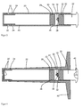
- FIG. 3 shows a schematic cross-sectional view of another device according to the invention, which has a hollow body 20 with a cylindrical cavity. At one end of the hollow body 20 a plurality of openings 22 are arranged in the walls of the hollow body 20, which connect the cavity of the hollow body 20 with the surroundings of the hollow body 20. In front of the inside of the openings 20 is a perforated rubber sleeve 24 arranged, which prevents uncontrolled outflow of a fluid medium from the cavity.
- an overflow channel 26 is arranged in the inner wall of the hollow body 20, which is arranged.
- a piston 28 is arranged in the cavity of the hollow body 20, which closes tightly with an O-ring seal 30 against the inner walls of the cavity of the hollow body 20 and thereby the cavity of the hollow body 20 in a first part (in FIG. 3 left) and in a second part (in FIG. 3 right).
- the two parts of the cavity of the hollow body 20 are connected to each other in the illustrated initial position of the piston 28 via the overflow 26.
- the hollow body 20 is opened on the opposite side of the openings 22 via a closure opening with an internal thread.
- a screw cap 32 is arranged, which has an external thread, via which the screw cap 32 can be screwed into the closure opening of the hollow body 20.
- a seal 33 is arranged, which seals the screw cap 32 and the closure opening and thus the second part of the cavity of the hollow body 20 to the outside when the screw cap 32 is screwed into the closure opening.
- a plunger 34 is arranged, with which the piston 28 is pressed into the interior of the cavity of the hollow body 20 when the screw cap 32 is completely screwed into the hollow body 20. As a result, the piston 28 is pushed deeper into the interior of the cavity, so that the overflow channel 26 is then arranged completely in the second part of the cavity and thus no longer interconnects the cavities.
- FIG. 4 shows a schematic cross-sectional view of a medical implant according to the invention, which analogous to the device according to FIG. 3 is constructed.
- the medical implant after FIG. 4 differs from the device FIG. 3 in that at the front end of the medical implant or the hollow body 20 of the medical implant, an additional opening 22 on the end face (in FIG. 4 is left), which is also sealed by the perforated rubber sleeve 24.
- the medical implant has a plate 40 at the end of the hollow body 20 opposite the openings 22.
- the screw cap 32 of in FIG. 4 shown medical implant a Phillips is arranged, with which the screw cap 32 is screwed into the cavity with a Phillips screwdriver. Except for these differences, the medical implant is after FIG. 4 like the device after FIG. 3 built up.
- the medical implant can be, for example, a pin, a screw or a bolt, which is used for stabilization in a bone an implant or a spacer.
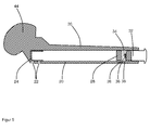
- FIG. 5 shows a schematic cross-sectional view of a spacer according to the invention, the analog of the device according to FIG. 3 or the medical implant FIG. 4 is constructed.
- the spacer forms with its hollow body 20 a femur (thigh bone), which ends a femoral head 44.
- the spacer serves to be used as an exchange for a final prosthesis in a cavity in the body, there to fight a source of infection.
- the embodiments according to the FIGS. 3, 4 and 5 they all work on the same principle.
- the piston 28 is initially in the initial position shown.
- the closure cap 32 is not inserted and thus the closure opening (in the FIGS. 3 to 5 right) open.
- An aqueous solution with a suitable combination of active ingredients mixed by the physician for the application is introduced into the hollow space of the hollow body 20 and also flows via the overflow channel 26 into the front (first) part of the hollow space.
- the screw cap 32 is screwed into the closure opening.
- the piston 28 is pushed deeper into the interior of the cavity, pushed past the overflow 26 and thereby separated the cavity into two parts.
- the device after FIG. 3 , the medical implant after FIG. 4 or the spacer after FIG. 5 are then ready for use and can be used as part of an operation in the body of a patient.
- the water of the aqueous solution which is also in the second part of the cavity, reacts with the metal of the metal plate 38. This produces gaseous hydrogen.
- the sponge 36 serves to ensure wetting of the metal plate 38 with the aqueous solution of active substance. The sponge 36 sucks to full with the aqueous solution.
- the hydrogen gas expands in the second part of the cavity (into the FIGS. 3 to 5 right) and thereby drives the piston 28 in the direction of the openings 22.
- the water in the aqueous drug solution or the pharmaceutically active substance solution chemically reacts with the magnesium and / or iron on the metal surface of the metal platelets 38 to corrode the metal or metals to form metal oxides to form gaseous hydrogen.
- the resulting hydrogen gas has a substantially larger volume under normal conditions so that it expands in the second part of the cavity, thereby driving the piston 28 towards the openings 22 and thereby the aqueous solution to the first part of the cavity through the perforated rubber sleeve 24 and the openings 22 pushes out.
- the chemical reaction of the corrosion of the metal plate 38 proceeds so slowly that the aqueous solution is pushed out of the openings 22 only slowly and therefore the device, the medical implant or the spacer emits the active ingredients uniformly over a long period of time.
- the duration and the rate of hydrogen evolution and thus the drug release of the device can be adjusted by the choice of reducing agent, that is, by the choice of the metals of the alloy and their surface finish.
- metal plate 38 may also be the inner wall of the second cavity, the second part of the cavity facing side of the piston 28 and / or the entire end face of the screw cap 32 made of a metal or a metal alloy with a negative standard potential or with such a metal or coated such a metal alloy.
- a pressure relief valve included in the piston 28, so that upon the formation of excessive pressure in the second part of the cavity, a connection is generated by the piston 28 in the first part of the cavity.
- the overflow channel 26 can be omitted.
- the two parts of the cavity are then always separated from each other.
- a fluid agent is introduced.
- the piston 28 is used.
- water or, theoretically, another gas-generating propellant can be introduced into the second part of the cavity.
- the second part of the cavity is closed.
- On the plunger 34 can be omitted in this embodiment.
Landscapes
- Health & Medical Sciences (AREA)
- Life Sciences & Earth Sciences (AREA)
- Medicinal Chemistry (AREA)
- Chemical & Material Sciences (AREA)
- Animal Behavior & Ethology (AREA)
- Veterinary Medicine (AREA)
- Public Health (AREA)
- General Health & Medical Sciences (AREA)
- Epidemiology (AREA)
- Engineering & Computer Science (AREA)
- Dermatology (AREA)
- Biomedical Technology (AREA)
- Pharmacology & Pharmacy (AREA)
- Oral & Maxillofacial Surgery (AREA)
- Transplantation (AREA)
- Bioinformatics & Cheminformatics (AREA)
- Molecular Biology (AREA)
- Neurosurgery (AREA)
- Anesthesiology (AREA)
- Vascular Medicine (AREA)
- Heart & Thoracic Surgery (AREA)
- Hematology (AREA)
- Communicable Diseases (AREA)
- Oncology (AREA)
- Chemical Kinetics & Catalysis (AREA)
- General Chemical & Material Sciences (AREA)
- Nuclear Medicine, Radiotherapy & Molecular Imaging (AREA)
- Organic Chemistry (AREA)
- Infusion, Injection, And Reservoir Apparatuses (AREA)
- Prostheses (AREA)
- Materials For Medical Uses (AREA)
- Pharmaceuticals Containing Other Organic And Inorganic Compounds (AREA)
Abstract
Description
Die Erfindung betrifft eine Vorrichtung zur Freisetzung eines Wirkstoffs sowie ein Verfahren zur Freisetzung eines Wirkstoffs und ein medizinisches Implantat aufweisend eine solche Vorrichtung.The invention relates to a device for releasing an active substance and to a method for releasing an active substance and to a medical implant comprising such a device.
Die Vorrichtung und das Verfahren sind zur aktiven, kontinuierlichen Wirkstofffreisetzung, insbesondere der lokalen Freisetzung von antibiotischen Wirkstoffen bestimmt. Die Wirkstofffreisetzungssysteme können in Form von Spacern, als aktiver Bestandteil von Spacern und auch als Implantat Verwendung finden. Grundsätzlich sind solche Verfahren und Vorrichtungen nicht zur Einnahme vorgesehen, sondern werden mit in den Körper implantierten Vorrichtungen mit Behältnissen für den Wirkstoff umgesetzt. Die Erfindung befasst sich dabei im speziellen mit sogenannten Spacern, die als zwischenzeitlicher Ersatz für Endoprothesen im Körper eingesetzt werden, um eine Infektion des umliegenden Gewebes zu bekämpfen.The device and method are intended for active, continuous drug release, in particular the local release of antibiotic agents. The drug release systems can be used in the form of spacers, as an active component of spacers and also as an implant. In principle, such methods and devices are not intended for use, but are implemented with devices implanted in the body with containers for the active ingredient. The invention is particularly concerned with so-called spacers, which are used as an interim replacement for endoprostheses in the body to combat infection of the surrounding tissue.
Zementierte und nichtzementierte Totalgelenkendoprothesen (TEP) sind heute Stand der Technik in der Orthopädie. Leider sind gibt es eine geringe Anzahl von Früh- und Spätinfektionen bei TEPs. Infizierte TEPs machen im Allgemeinen eine Wechsel-Operation notwendig. Diese Wechsel-Operationen werden in einzeitige und zweizeitige Operationen unterteilt. Bei der zweizeitigen Wechsel-Operation wird zuerst die infizierte TEP entfernt, das infizierte Knochen- und Weichgewebe debridiert und anschließend ein Spacer als temporärer Platzhalter eingesetzt. Dabei kommen üblicherweise industriell vorgefertigte Spacer zur Anwendung, die ein Antibiotikum enthalten können, oder auch individuelle aus PMMA-Knochenzement gefertigte Spacer, die entweder frei geformt, oder auch unter Verwendung von Gießformen vom Operateur selbst gefertigt werden. Diese Spacer können durch individuelle Dotierung des eingesetzten PMMA-Knochenzements mit Antibiotika, entsprechend dem Antibiogramm der der Infektion zu Grunde liegenden Keime patientenspezifisch gefertigt werden.Cemented and non-cemented total joint endoprostheses (TEP) are today the state of the art in orthopedics. Unfortunately, there are a small number of early and late infections in TEPs. Infected TEPs generally require a replacement surgery. These switching operations are divided into one-time and two-time operations. In the two-time change operation, the infected TEP is first removed, the deboned infected bone and soft tissue and then a spacer used as a temporary placeholder. In this case, usually industrially prefabricated spacers are used, which may contain an antibiotic, or individual spacer made of PMMA bone cement, which are either free-formed, or even made using casting molds by the surgeon himself. These spacers can be made patient-specific by individual doping of the PMMA bone cement used with antibiotics, according to the antibiogram of the germs underlying the infection.
Spacer verbleiben meistens mehrere Wochen, vielfach 6 bis 8 Wochen, im Patienten, bis sich die Infektion beruhigt hat. Anschließend wird in einer zweiten Operation der Spacer entfernt, das angrenzende Gewebe nochmals debridiert und dann wird die Revisionsprothese eingesetzt, die zementiert oder auch zementfrei sein kann.Spacers usually remain in the patient for several weeks, often 6 to 8 weeks, until the infection calms down. Subsequently, in a second operation, the spacer is removed, the adjacent tissue is debrided again, and then the revision prosthesis is used, which may be cemented or even cementless.
Neben den industriell gefertigten PMMA-Spacern und den individuell gefertigten PMMA-Spacern, die ein Antibiotikum oder auch mehrere Antibiotika enthalten, wurden auch Spacer vorgeschlagen, die selbst keine Antibiotika enthalten. Diese Spacer enthalten Kavitäten, die vom medizinischen Anwender mit antibiotischen Lösungen befüllt werden können.In addition to the industrially produced PMMA spacers and the custom-made PMMA spacers containing an antibiotic or even several antibiotics, spacers were also proposed, which themselves contain no antibiotics. These spacers contain cavities that can be filled by the medical user with antibiotic solutions.
In der
Ein ähnlicher Spacer wurde in der
Mit der
Bei diesen befüllbaren Spacern und anderen mit Wirkstofflösungen befüllbaren Wirkstoffträgern treten die in flüssiger gelöster Form vorliegenden Wirkstoffe durch einfache Diffusion aus.With these fillable spacers and other drug carriers which can be filled with active ingredient solutions, the active substances present in liquid dissolved form emerge by simple diffusion.
Nachteilig ist hieran, dass es dadurch zu Schwankungen in der Wirkstofffreisetzung kommen kann, dass die Wirkstofffreisetzung zu früh beendet wird und dass es zu einer asymptotischen Abnahme der Freisetzung der Wirkstoffe kommen kann.A disadvantage of this is that it may cause fluctuations in the drug release that the drug release is terminated too early and that it may lead to an asymptotic decrease in the release of the active ingredients.
Die Aufgabe der Erfindung besteht also darin, die Nachteile des Stands der Technik zu überwinden. Insbesondere soll eine Vorrichtung und ein Verfahren bereitgestellt werden, bei denen Wirkstoffe über einen Zeitraum von bis zu mehreren Wochen kontinuierlich und möglichst auch gleichmäßig freigesetzt werden können.The object of the invention is therefore to overcome the disadvantages of the prior art. In particular, a device and a method are to be provided in which active ingredients can be released continuously over a period of up to several weeks and even if possible evenly.
Die Aufgaben der Erfindung werden gelöst durch eine Vorrichtung zur Freisetzung eines fluiden Wirkstoffs aufweisend wenigstens einen Hohlraum, in dem der fluide Wirkstoff enthalten ist, wobei in der Vorrichtung Wasser und ein Reduktionsmittel enthalten sind, die miteinander in Verbindung stehen oder miteinander in Verbindung bringbar sind, so dass durch eine chemische Reaktion des Wassers mit dem Reduktionsmittel in der Vorrichtung ein Gas entsteht und das Gas derart mit dem fluiden Wirkstoff in Wirkverbindung steht, das der entstehende Gasdruck den fluiden Wirkstoff aus zumindest einer Öffnung des Hohlraums aus der Vorrichtung herausdrückt.The objects of the invention are achieved by a device for releasing a fluid substance having at least one cavity in which the fluid agent is contained, wherein the device contains water and a reducing agent, which are in communication with each other or are in communication with each other, so that a gas is formed by a chemical reaction of the water with the reducing agent in the device and the gas is so in operative connection with the fluid active ingredient, which is the resulting gas pressure pushes the fluid agent from at least one opening of the cavity from the device.
Bevorzugt ist dabei vorgesehen, dass das entstehende Gas Wasserstoff ist.It is preferably provided that the resulting gas is hydrogen.
Gemäß einer Weiterbildung der Erfindung kann vorgesehen sein, dass das Wasser für die chemische Reaktion ein Teil einer flüssigen wässrigen Lösung ist, die den fluiden Wirkstoff bildet, wobei bevorzugt der fluide Wirkstoff eine wässrige Lösung aufweisend zumindest eine pharmazeutisch aktive Substanz ist, besonders bevorzugt eine wässrige Lösung aufweisend zumindest ein Antibiotikum.According to a development of the invention, it can be provided that the water for the chemical reaction is part of a liquid aqueous solution which forms the fluid active substance, wherein the fluid active substance is preferably an aqueous solution comprising at least one pharmaceutically active substance, particularly preferably an aqueous one Solution comprising at least one antibiotic.
Dies macht den Aufbau besonders einfach und kostengünstig umzusetzen, da der fluide Wirkstoff auch gleichzeitig das Treibmittel (das Gas) zum Austreiben des fluiden Wirkstoffs aus der Vorrichtung bereithält.This makes the construction particularly simple and inexpensive to implement, since the fluid agent also simultaneously holds the propellant (the gas) for expelling the fluid agent from the device.
Ferner kann vorgesehen sein, dass das Reduktionsmittel eine metallische Oberfläche ist, wobei bevorzugt die metallische Oberfläche ein negatives Standardpotential aufweist, besonders bevorzugt die metallische Oberfläche Magnesium, Eisen oder Legierungen aufweisend Magnesium und/oder Eisen beinhaltet oder daraus besteht.Furthermore, it can be provided that the reducing agent is a metallic surface, wherein preferably the metallic surface has a negative standard potential, particularly preferably the metallic surface includes or consists of magnesium, iron or alloys comprising magnesium and / or iron.
Solche Oberflächen korrodieren langsam, so dass eine gleichmäßige und langfristige Freisetzung des Wirkstoffs mit dem Aufbau sichergestellt werden kann.Such surfaces slowly corrode, so that a uniform and long-term release of the active ingredient can be ensured with the structure.
Dabei kann vorgesehen sein, dass das Reduktionsmittel Magnesium und ein Edelmetall ist, die eine elektrochemische Zelle bilden, oder das Reduktionsmittel eine Mischung eines schnell korrodierenden Metalls und eines langsam korrodierenden Metalls ist.In this case it can be provided that the reducing agent is magnesium and a noble metal, which form an electrochemical cell, or the reducing agent is a mixture of a rapidly corroding metal and a slowly corroding metal.
Mit dieser Variante kann die Freisetzung des Gases besonders gut und auch langfristig genau eingestellt werden.With this variant, the release of the gas can be adjusted particularly well and also over the long term.
Mit einer besonders bevorzugten Weiterbildung der Erfindung kann vorgesehen sein, dass mindestens eine solche Masse an Reduktionsmittel und/oder an Wasser in der Vorrichtung angeordnet ist, dass eine solche Menge an Gas entsteht, die zumindest 30% des Volumens des Hohlraums einnimmt, bevorzugt zumindest 50% des Volumens des Hohlraums, besonders bevorzugt zumindest 80% des Volumens des Hohlraums.With a particularly preferred development of the invention, provision may be made for at least one mass of reducing agent and / or water to be arranged in the device such that an amount of gas is formed which occupies at least 30% of the volume of the cavity, preferably at least 50 % of the volume of the cavity, more preferably at least 80% of the volume of the cavity.
Durch diese Mengen wird sichergestellt, dass ein ausreichender Teil des Wirkstoffs aus der Vorrichtung ausgetrieben wird. Ganz besonders bevorzugt ist vorgesehen, dass eine solche Masse an Reduktionsmittel in der Vorrichtung angeordnet ist, dass eine solche Menge an Gas entsteht, die 70% bis 90% des Volumens des Hohlraums entspricht. Dann ist genau die richtige Menge an Reduktionsmittel vorhanden, so dass auch bei einem längeren Verbleib der Vorrichtung im Körper nicht unnötig viel Gas erzeugt wird, das vom Körper resorbiert werden muss.These quantities ensure that a sufficient portion of the drug is expelled from the device. It is particularly preferred that such Mass of reducing agent is arranged in the device that such an amount of gas is produced, which corresponds to 70% to 90% of the volume of the cavity. Then exactly the right amount of reducing agent is present, so that even with a longer whereabouts of the device in the body not unnecessarily much gas is generated, which must be absorbed by the body.
Mit einer weiteren besonders bevorzugten Variante der Erfindung kann vorgesehen sein, dass der wenigstens eine Hohlraum zumindest bereichsweise durch eine oder mehrere kapillarförmige Röhren in der Vorrichtung gebildet ist, die sich auf einer Seite bis zu einer Öffnung in der Oberfläche der Vorrichtung erstrecken, wobei bevorzugt die Hohlräume durch eine Mehrzahl von zumindest bereichsweise parallelen kapillarförmigen Röhren gebildet sind.With a further particularly preferred variant of the invention can be provided that the at least one cavity is at least partially formed by one or more capillary tubes in the device, which extend on one side to an opening in the surface of the device, wherein preferably Cavities are formed by a plurality of at least partially parallel capillary-shaped tubes.
Dieser Aufbau ist sehr einfach und sehr sicher. Durch die kapillarförmigen Röhren wird sichergestellt, dass die Oberflächenspannung einer enthaltenen wässrigen Lösung dafür sorgt, dass zunächst die wässrige Lösung aus den kapillarförmigen Röhren ausgetrieben wird, da das Gas nicht durch die Kapillaren an der wässrigen Lösung vorbei gedrückt werden kann. Es ist also erfindungsgemäß besonders bevorzugt vorgesehen, dass die kapillarförmigen Röhren Kapillaren sind. Vorzugsweise haben die Kapillaren einen Durchmesser von weniger als 500 µm, besonders bevorzugt von weniger als 200 µm.This setup is very simple and very safe. The capillary-shaped tubes ensure that the surface tension of an aqueous solution contained ensures that first the aqueous solution is expelled from the capillary-shaped tubes, since the gas can not be forced past the aqueous solution by the capillaries. It is therefore particularly preferred according to the invention for the capillary-shaped tubes to be capillaries. Preferably, the capillaries have a diameter of less than 500 microns, more preferably less than 200 microns.
Dabei kann vorgesehen sein, dass das Reduktionsmittel an dem zu der jeweiligen Öffnung gegenüberliegenden Ende der kapillarförmigen Röhre oder der kapillarförmigen Röhren angeordnet ist, wobei das Reduktionsmittel in dem Hohlraum angeordnet ist und nur über die Öffnung der Röhre mit der Oberfläche der Vorrichtung verbunden ist, wobei vorzugweise der fluide Wirkstoff als wässrige Lösung mit dem Reduktionsmittel in Kontakt steht.It can be provided that the reducing agent is disposed at the opposite end of the capillary tube or the capillary tubes to the respective opening, wherein the reducing agent is disposed in the cavity and is connected only via the opening of the tube with the surface of the device Preferably, the fluid agent is in contact with the reducing agent as an aqueous solution.
Das Gas entsteht so auf der gewünschten Seite der kapillarförmigen Röhren. Zudem können die kapillarförmigen Röhren vorzugsweise an der von der Öffnung nach außen abgewandten Seite der Röhren mit dem Reduktionsmittel beschichtet sein.The gas thus arises on the desired side of the capillary tubes. In addition, the capillary-shaped tubes may preferably be coated with the reducing agent on the side of the tubes facing away from the opening to the outside.
Gemäß einer alternativen, besonders bevorzugten Ausführungsform kann vorgesehen sein, dass in dem Hohlraum ein in Richtung der zumindest einen Öffnung des Hohlraums verschiebbarer Kolben angeordnet ist und der Kolben den Hohlraum in einen ersten Teil, der die zumindest eine Öffnung aufweist, und einen zweiten geschlossenen oder verschließbaren Teil unterteilt, wobei in dem ersten Teil der fluide Wirkstoff angeordnet ist und in dem zweiten Teil das Reduktionsmittel und Wasser angeordnet sind, so dass der entstehende Gasdruck in dem geschlossenen, zweiten Teil des Hohlraums den Kolben in Richtung der zumindest einen Öffnung treibt und dadurch den fluiden Wirkstoff aus dem ersten Teil des Hohlraums durch die zumindest eine Öffnung aus der Vorrichtung herausdrückt.According to an alternative, particularly preferred embodiment it can be provided that a piston displaceable in the direction of the at least one opening of the cavity is arranged in the cavity and the piston surrounds the cavity into a first part which has the at least one opening and a second closed or subdivided, wherein in the first part of the fluid agent is arranged and in the second part, the reducing agent and water are arranged, so that the resulting gas pressure in the closed, second part of the cavity, the piston towards the at least one opening drives and thereby pushes the fluid agent from the first part of the cavity through the at least one opening from the device.
Durch diesen Aufbau kann auch eine größere Menge des Wirkstoffs auf dem gleichen Raum langsam freigesetzt werden, als dies bei der Verwendung mit Kapillaren möglich wäre, da hier der Hohlraum als Nutzraum im Vergleich zu den äußeren Abmessungen der Vorrichtung wesentlich größer ist.By this construction, a larger amount of the active ingredient in the same space can be released slowly, as would be possible when used with capillaries, since here the cavity is significantly larger than the useful space compared to the outer dimensions of the device.
Dabei kann vorgesehen sein, dass in der Innenwand des Hohlraums ein Überströmkanal angeordnet ist, der in einer Ausgangsstellung des Kolbens den ersten Teil und den zweiten Teil des Hohlraums verbindet und der zweite Teil des Hohlraums eine Verschlussöffnung aufweist, die durch einen Verschluss verschließbar oder geschlossen ist, so dass der Hohlraum in beiden Teilen mit der gleichen wässrigen Lösung, die den fluiden Wirkstoff bildet und das flüssige Wasser für die chemische Reaktion bereitstellt, durch die Verschlussöffnung befüllbar ist, wobei der Verschluss derart aufgebaut ist, dass er beim Verschließen der Verschlussöffnung den Kolben in dem Hohlraum in Richtung der zumindest einen Öffnung an dem Überströmkanal vorbei schiebt, so dass der Überströmkanal den ersten und den zweiten Teil des Hohlraums bei vollständig eingesetztem Verschluss nicht mehr verbindet und der Kolben den ersten und den zweiten Teil des Hohlraums gasdicht voneinander trennt.It can be provided that in the inner wall of the cavity an overflow channel is arranged which connects the first part and the second part of the cavity in an initial position of the piston and the second part of the cavity has a closure opening which can be closed or closed by a closure such that the cavity in both parts can be filled with the same aqueous solution which forms the fluid agent and provides the liquid water for the chemical reaction through the closure opening, the closure being constructed to close the piston when closing the closure opening in the cavity in the direction of the at least one opening pushes past the overflow channel, so that the overflow no longer connects the first and the second part of the cavity with fully inserted closure and the piston the first and the second part of the cavity gas-tight from each other.
Durch diesen Aufbau kann der fluide Wirkstoff auch als Quelle für das Gas verwendet werden.With this structure, the fluid agent can also be used as a source of the gas.
Dabei kann wiederum vorgesehen sein, dass an dem Verschluss zumindest ein Steg und/oder zumindest ein Hohlzylinder angeordnet ist, der sich bei eingesetztem Verschluss in den ersten Teil des Hohlraums erstreckt und beim Verschließen den Kolben in Richtung der zumindest einen Öffnung an dem Überströmkanal vorbei schiebt.It can again be provided that at least one web and / or at least one hollow cylinder is arranged on the closure which extends into the first part of the cavity when the closure is inserted and pushes the piston past the at least one opening on the overflow channel when closing ,
Dadurch sind die beiden Hohlraumteile leicht und automatisch beim Verschließen des zweiten Hohlraums voneinander trennbar.As a result, the two cavity parts are easily and automatically separated from each other when closing the second cavity.
Gemäß einer Weiterbildung der Erfindung kann vorgesehen sein, dass an dem Verschluss ein Gewinde, vorzugsweise ein Außengewinde angeordnet ist und dass der Hohlraum an der Verschlussöffnung ein Gegengewinde, vorzugsweise ein Innengewinde aufweist, so dass der Verschluss den Kolben bei Einschrauben der Verschlusses in Richtung der zumindest einen Öffnung an dem Überlaufkanal vorbei schiebt.According to one embodiment of the invention can be provided that on the closure a thread, preferably an external thread is arranged and that the cavity at the closure opening has a counter-thread, preferably an internal thread, so that the closure of the piston when screwing the closure in the direction of at least pushes an opening past the overflow channel.
Hierdurch ist ein kontrolliertes Vortreiben des Kolbens durch den Verschluss (beziehungsweise die Verschlusskappe beziehungsweise die Schraubkappe) möglich. Zudem kann das Gewinde eine Dichtfunktion erfüllen.As a result, a controlled pushing the piston through the closure (or the cap or the screw cap) is possible. In addition, the thread can fulfill a sealing function.
Ferner kann erfindungsgemäß vorgesehen sein, dass wenigstens ein Ventilelement zum Gasablass bei Überdruck an dem zweiten Teil des Hohlraums angeordnet ist, vorzugsweise eine Berstscheibe oder ein Überdruckventil an dem zweiten Teil des Hohlraums angeordnet ist, wobei das Ventilelement bevorzugt in dem Kolben angeordnet ist, so dass bei einem ausreichenden Überdruck im zweiten Teil des Hohlraums eine Öffnung zum zweiten Teil des Hohlraums im Kolben entsteht.Furthermore, it can be provided according to the invention that at least one valve element for gas outlet is arranged at overpressure on the second part of the cavity, preferably a rupture disk or a pressure relief valve is arranged on the second part of the cavity, wherein the valve element is preferably arranged in the piston, so that at a sufficient pressure in the second part of the cavity an opening to the second part of the cavity in the piston is formed.
Dies erhöht die Sicherheit der Vorrichtung, da so ein unerwünschter Überdruck bei vermieden werden kann.This increases the safety of the device, as an undesirable overpressure can be avoided at.
Erfindungsgemäße Vorrichtungen können sich auch dadurch auszeichnen, dass der zumindest eine Hohlraum, insbesondere die kapillarförmigen Röhren aus synthetischen Polymeren und/oder partialsynthetischen Polymeren besteht oder bestehen.Devices according to the invention may also be distinguished by the fact that the at least one cavity, in particular the capillary-shaped tubes, consists or consist of synthetic polymers and / or partially synthetic polymers.
Diese Werkstoffe sind für erfindungsgemäße Vorrichtungen besonders gut verwendbar und geeignet.These materials are particularly suitable and suitable for devices according to the invention.
Gemäß einer bevorzugten Weiterbildung der Erfindung kann vorgesehen sein, dass die zumindest eine Öffnung durch einen perforierten Körper geschlossen ist, vorzugsweise durch einen perforierte Gummikörper geschlossen ist, wobei der perforierte Körper im Bereich der zumindest einen Öffnung angeordnet ist.According to a preferred embodiment of the invention can be provided that the at least one opening is closed by a perforated body, preferably closed by a perforated rubber body, wherein the perforated body is arranged in the region of at least one opening.
Hierdurch kann ein vorzeitiges ungewolltes Austreten des fluiden Wirkstoffs aus der Vorrichtung vermieden werden.As a result, premature unwanted leakage of the fluid agent from the device can be avoided.
Die Aufgaben der Erfindung werden auch gelöst durch ein medizinisches Implantat aufweisend eine solche Vorrichtung, wobei bevorzugt das medizinische Implantat ein Hüftspacer oder ein Kniespacer ist.The objects of the invention are also achieved by a medical implant having such a device, wherein preferably the medical implant is a hip spacer or a knee spacer.
Ferner werden die Aufgaben der Erfindung gelöst durch ein Verfahren zur Freisetzung eines fluiden Wirkstoffs aus einem Hohlraum eines medizinischen Implantats, bei dem ein Gas durch eine chemische Reaktion von flüssigem Wasser mit einem Reduktionsmittel erzeugt wird und der entstehende Gasdruck zum Austreiben des fluiden Wirkstoffs aus zumindest einer Öffnung des Hohlraums verwendet wird.Further, the objects of the invention are achieved by a method for releasing a fluid agent from a cavity of a medical implant in which a gas is generated by a chemical reaction of liquid water with a reducing agent and the resulting gas pressure for expelling the fluid agent from at least one Opening the cavity is used.
Das erfindungsgemäße Verfahren wird vorzugsweise mit einer erfindungsgemäßen Vorrichtung umgesetzt.The inventive method is preferably implemented with a device according to the invention.
Bei dem Verfahren kann vorgesehen sein, dass als Gas Wasserstoff erzeugt wird.In the method can be provided that hydrogen is generated as the gas.
Die Verwendung von Wasserstoff als Gas hat den Vorteil, dass das Wasser der wässrigen Lösungen als Quelle für das Gas verwendet werden kann und so keine zusätzlichen Gasquellen mehr notwendig sind.The use of hydrogen as a gas has the advantage that the water of the aqueous solutions can be used as a source of the gas and so no additional gas sources are more necessary.
Es wird auch vorgeschlagen. dass als Reduktionsmittel eine metallische Oberfläche verwendet wird, bevorzugt eine metallische Oberfläche mit einem negativen Standardpotenzial verwendet wird, besonders bevorzugt Magnesium, Eisen oder Legierungen aufweisend Magnesium und/oder Eisen als metallische Oberfläche verwendet wird, wobei das Gas, insbesondere der Wasserstoff durch eine Korrosion der metallischen Oberfläche erzeugt wird.It is also suggested. that a metallic surface is used as reducing agent, preferably a metallic surface with a negative standard potential is used, particularly preferably magnesium, iron or alloys comprising magnesium and / or iron is used as the metallic surface, wherein the gas, in particular the hydrogen by corrosion of the metallic surface is generated.
Solche Oberflächen korrodieren langsam, so dass eine gleichmäßige und langfristige Freisetzung des Wirkstoffs mit dem Aufbau sichergestellt werden kann.Such surfaces slowly corrode, so that a uniform and long-term release of the active ingredient can be ensured with the structure.
Dabei kann vorgesehen sein, dass als Reduktionsmittel Magnesium und ein Edelmetall verwendet wird und das Gas durch eine elektrochemische Reaktion erzeugt wird.It can be provided that as reducing agent magnesium and a noble metal is used and the gas is generated by an electrochemical reaction.
Diese Metalle korrodieren mit Wasser ausreichend stark aber auch ausreichend langsam, um eine langfristige gleichmäßige Freisetzung des fluiden Wirkstoffs sicherzustellen. Gleichzeitig sind diese Metalle zur Verwendung im menschlichen Körper aus medizinischer Sicht unbedenklich.These metals corrode with water sufficiently strong but also sufficiently slowly to ensure long-term uniform release of the fluid agent. At the same time, these metals are safe for use in the human body from a medical point of view.
Alternativ kann vorgesehen sein, dass als Reduktionsmittel eine Mischung eines schnell korrodierenden Metalls und eines langsam korrodierenden Metalls verwendet wird.Alternatively, it may be provided that a mixture of a rapidly corroding metal and a slowly corroding metal is used as the reducing agent.
Hierdurch kann die Korrosion und damit die Fließgeschwindigkeit des fluiden Wirkstoffs noch genauer eingestellt werden.As a result, the corrosion and thus the flow rate of the fluid substance can be adjusted even more precisely.
Schließlich wird mit dem erfindungsgemäßen Verfahren vorgeschlagen, dass das flüssige Wasser, das zur chemischen Reaktion verwendet wird, Teil einer wässrigen Lösung ist, die den fluiden Wirkstoff bildet, wobei bevorzugt eine wässrige, pharmazeutisch aktive Lösung als fluider Wirkstoff verwendet wird, besonders bevorzugt eine wässrige Lösung aufweisend zumindest ein Antibiotikum.Finally, it is proposed with the method according to the invention that the liquid water used for the chemical reaction is part of an aqueous solution which forms the fluid active substance, an aqueous, pharmaceutically active solution preferably being used as the fluid active substance, particularly preferably an aqueous one Solution comprising at least one antibiotic.
Erfindungsgemäß ist ferner ein Verfahren zur Wirkstofffreisetzung, das dadurch charakterisiert ist, dass eine wässrige Wirkstofflösung aus einem Hohlraum durch Wasserstoff ausgetrieben wird, der durch Korrosion wenigstens eines Metalls oder einer Metalllegierung bei Kontakt mit einer wässrigen Elektrolytlösung entsteht, wobei das wenigstens eine Metall oder die wenigstens eine Metalllegierung zu mindestens in einem Teil des Hohlraums angeordnet ist.The invention further provides a method of drug release characterized in that an aqueous drug solution is expelled from a cavity by hydrogen resulting from corrosion of at least one metal or metal alloy on contact with an aqueous electrolyte solution, wherein the at least one metal or at least a metal alloy is disposed at least in a part of the cavity.
Der Erfindung liegt die überraschende Erkenntnis zugrunde, dass es mit dem erfindungsgemäßen Verfahren und der erfindungsgemäßen Vorrichtung gelingt, Wirkstoffe mit einem aktiven Transportmechanismus über einen Zeitraum bis zu mehreren Wochen kontinuierlich freizusetzen, wobei dieser Transportmechanismus bei Körpertemperatur aktiv ist, ohne dass dazu eine externe oder interne Energiequelle notwendig ist. Die Erfindung beruht auf der überraschenden Erkenntnis, dass Magnesium, Magnesiumlegierungen, Eisen und Eisenlegierungen unter der Einwirkung von Elektrolytlösungen und auch Körperflüssigkeiten, wie Blut, korrodieren, wobei als Nebenprodukt Wasserstoff frei wird und die Produkte dieser chemischen Reaktion (also das Wasserstoffgas) als Treibmittel zum Austragen eines Wirkstoffs aus einem Hohlraum verwendet werden können. Die Korrosionsgeschwindigkeit ist abhängig vom verwendeten Metall beziehungsweise der verwendeten Metalllegierung, vom Oberfläche-Volumen-Verhältnis des Metalls beziehungsweise der Metalllegierung und reicht bei geeignetem Aufbau über einen Zeitraum von mehreren Wochen. Das bedeutet, dass bei dem Korrosionsprozess kontinuierlich Wasserstoff freigesetzt wird, der zum Austreiben des Wirkstoffs aus dem Hohlraum verwendet wird. Bei der Korrosion von Magnesium entsteht Magensiumhydroxid, das ungiftig und völlig unbedenklich ist. Magnesium ist ein natürlicher Bestandteil des humanen Organismus. Eisen korrodiert unter Bildung von Eisenoxiden. Diese sind auch als medizinisch unbedenklich anzusehen. Eisen ist ein natürlicher Bestandteil des humanen Organismus und ist für den Menschen lebenswichtig. Daher sind diese beiden Metalle zur Anwendung in einer erfindungsgemäßen Vorrichtung und mit einem erfindungsgemäßen Verfahren besonders bevorzugt.The invention is based on the surprising finding that with the method according to the invention and the device according to the invention it is possible to continuously release active substances with an active transport mechanism over a period of up to several weeks, this transport mechanism being active at body temperature without an external or internal one Energy source is necessary. The invention is based on the surprising finding that magnesium, magnesium alloys, iron and iron alloys corrode under the action of electrolyte solutions and body fluids such as blood, as a byproduct releases hydrogen and the products of this chemical reaction (ie the hydrogen gas) as a blowing agent for Discharging a drug from a cavity can be used. The corrosion rate depends on the metal used or the metal alloy used, the surface-to-volume ratio of the metal or the metal alloy and, with a suitable structure, lasts over a period of several weeks. This means that in the corrosion process continuously hydrogen is released, which is used to expel the active ingredient from the cavity. The corrosion of magnesium produces magnesium hydroxide, which is non-toxic and completely harmless. Magnesium is a natural component of the human organism. Iron corrodes to form iron oxides. These are also to be regarded as medically safe. Iron is a natural component of the human organism and is vital to humans. Therefore, these two metals are particularly preferred for use in a device according to the invention and with a method according to the invention.
Die Grundidee der Erfindung beruht darauf, den bei der Korrosion von Metallen zwangsläufig freigesetzten Wasserstoff als Antrieb zur kontinuierlichen Freisetzung von pharmazeutischen Wirkstofflösungen einzusetzen. Eine Vielzahl von in Wasser löslichen Wirkstoffen liegt in der Salzform vor und bilden nach ihrer Auflösung in Wasser Elektrolytlösungen. Beispielhaft sind dafür die Antibiotika Gentamicinsulfat, Tobramycinsulfat, Clindamycinhydrochlorid und Vancomycinhydrochlorid. Im Fall von nichtsalzförmigen in Wasser löslichen oder zu mindestens suspendierbaren Wirkstoffen kann der Wirkstoff auch in medizinisch übliche Elektrolytlösungen, wie physiologische Kochsalzlösungen oder Ringer-Lösungen gelöst oder suspendiert werden.The basic idea of the invention is based on the use of the inevitably released in the corrosion of metals hydrogen as a drive for the continuous release of pharmaceutical drug solutions. A variety of water-soluble drugs are in the salt form and form after their dissolution in water electrolyte solutions. Exemplary are the antibiotics gentamicin sulfate, tobramycin sulfate, clindamycin hydrochloride and vancomycin hydrochloride. In the case of non-salt-soluble or water-soluble or at least suspendable active ingredients, the active compound can also be dissolved or suspended in medically customary electrolyte solutions, such as physiological saline solutions or Ringer's solutions.
Erfindungsgemäß und eine Ausführungsvariante der Erfindung ist eine Vorrichtung zur Wirkstofffreisetzung, die dadurch charakterisiert ist, dass
- a) zumindest ein kapillarförmiger Hohlraum, der mindestens eine Öffnung besitzt, in der Vorrichtung angeordnet ist,
- b) wobei der Hohlraum mit wässriger Wirkstofflösung zu mindestens teilweise gefüllt ist,
- c) wobei die wässrige Wirkstofflösung mindestens an einer Stelle mit einem Metall oder einer Metalllegierung in Kontakt steht,
- d) wobei das Metall oder die Metalllegierung durch eine gasdichte Umhüllung eingeschlossen ist und
- e) wobei das Metall oder die Metalllegierung flüssigkeitsdurchlässig und gasdurchlässig durch mindestens eine Öffnung der Umhüllung mit dem wenigstens einen kapillarförmigen
- a) at least one capillary-shaped cavity having at least one opening is arranged in the device,
- b) wherein the cavity is at least partially filled with aqueous solution of active substance,
- c) wherein the aqueous solution of active substance is in contact with a metal or a metal alloy at least at one point,
- d) wherein the metal or metal alloy is enclosed by a gas-tight enclosure and
- e) wherein the metal or metal alloy is liquid-permeable and gas-permeable through at least one opening of the enclosure with the at least one capillary-shaped
Hohlraum verbunden ist, so dass der durch Korrosion des Metalls oder der Metalllegierung entstehende Wasserstoff und die wässrige Wirkstofflösung nur durch den mindestens einen kapillarförmigen Hohlkörper austreten können.Cavity is connected, so that the resulting by corrosion of the metal or the metal alloy hydrogen and the aqueous solution of active substance can escape only through the at least one capillary hollow body.
Das bedeutet, dass der fluide Wirkstoff, der eine wässrige Wirkstofflösung oder auch eine Wirkstoffsuspension sein kann, wird zuerst in den kapillarförmigen Hohlraum, zum Beispiel durch Aufsaugen, eingebracht. Die Wirkstofflösung kommt in Kontakt mit dem Metall oder der Metalllegierung. Der Korrosionsprozess setzt ein und dabei wird kontinuierlich Wasserstoff freigesetzt. Dieser treibt kontinuierlich die Wirkstofflösung beziehungsweise Wirkstoffsuspension aus dem kapillarförmigen Hohlraum.This means that the fluid active substance, which may be an aqueous active substance solution or even an active ingredient suspension, is first introduced into the capillary cavity, for example by suction. The drug solution comes into contact with the metal or metal alloy. The corrosion process starts and hydrogen is released continuously. This continuously drives the drug solution or drug suspension from the capillary cavity.
Eine vorteilhafte Ausgestaltung der Erfindung besteht darin, dass mindestens eine solche Masse an Metall oder Metalllegierung in der Vorrichtung angeordnet ist, dass durch Korrosion des Metalls oder der Metalllegierung ein Volumen an Wasserstoff freigesetzt wird, das bei Raumtemperatur mindestens 50 Volumenprozent des kapillarförmigen Hohlraums einnimmt.An advantageous embodiment of the invention is that at least one such mass of metal or metal alloy is arranged in the device that by corrosion of the metal or the metal alloy, a volume of hydrogen is released, which occupies at room temperature at least 50 percent by volume of the capillary cavity.
Für die Freisetzung von ausreichenden Volumina von Wasserstoff genügen kleinste Metallmengen. So setzt 1 mg Magnesium unter Standardbedingungen circa 0,9 ml Wasserstoff frei. Für die kontinuierliche Wirkstofffreisetzung sind Wasserstoff-Volumina von wenigen Millilitern völlig ausreichend. Daher genügen Metalmengen im Milligrammbereich zum Antrieb eines erfindungsgemäßen Freisetzungssystems.For the release of sufficient volumes of hydrogen smallest amounts of metal are sufficient. Thus, 1 mg of magnesium releases about 0.9 ml of hydrogen under standard conditions. Hydrogen volumes of a few milliliters are completely sufficient for the continuous release of active ingredient. Therefore, amounts of metal in the milligram range are enough to drive a release system according to the invention.
Erfindungsgemäß ist ferner, dass wenigstens zwei kapillarförmige Hohlräume vorhanden sind, wobei Kapillarbündel besonders bevorzugt sind. Die Kapillarbündel beziehungsweise die Bündel von kapillarförmigen Röhren können vorteilhaft in rohrförmigen oder auch beliebig anders geformten Behältern angeordnet sein, wobei mindestens ein Ende der Kapillarbündel für Flüssigkeiten und Gase offen sein muss. Besonders vorteilhaft ist es, wenn die Kapillarbündel in dem Behälter gasdicht mit einem Kunststoff vergossen sind. Die Behälter können einseitig durch Kappen mit Schraubgewinde oder mit durch Rastungen verriegelbaren Kappen verschlossen sein, wobei sich in der Innenseite der Schraubkappe das Metall beziehungsweise die Metalllegierung befindet. Ebenso ist es möglich, zwei Behälter mit Kapillarbündeln zu kombinieren, wobei beide Behälter gasdicht an jeweils einem Ende miteinander gekoppelt werden, wobei das Metall/Metalllegierung am Übergang zwischen den beiden Kapillarbündeln angeordnet ist. Im Rahmen der Erfindung kann es auch vorgesehen sein, dass die Innenseite der kapillarförmigen Hohlräume mit dem Metall oder der Metalllegierungen als Reduktionsmittel beschichtet ist.According to the invention, it is further provided that at least two capillary-shaped cavities are present, with capillary bundles being particularly preferred. The capillary bundles or the bundles of capillary-shaped tubes can advantageously be arranged in tubular or otherwise differently shaped containers, wherein at least one end of the capillary bundles must be open to liquids and gases. It is particularly advantageous if the capillary bundles in the container are sealed gas-tight with a plastic. The containers can be closed on one side by caps with a screw thread or with latches that can be locked by latching, with the metal or the metal alloy being located in the inside of the screw cap. It is also possible to combine two containers with Kapillarbündeln, wherein both containers are gas-tight coupled at one end to each other, wherein the metal / metal alloy is disposed at the transition between the two Kapillarbündeln. In the context of the invention it can also be provided that the inside of the capillary-shaped cavities is coated with the metal or the metal alloys as a reducing agent.
Es kann erfindungsgemäß ferner vorgesehen sein, dass die Kapillaren aus synthetischen Polymeren und/oder partialsynthetischen Polymeren bestehen.It may further be provided according to the invention that the capillaries consist of synthetic polymers and / or partially synthetic polymers.
Erfindungsgemäß ist weiterhin eine Vorrichtung zur Wirkstofffreisetzung, die dadurch charakterisiert ist, dass
- a) ein Hohlkörper in der Vorrichtung angeordnet ist, wobei der Hohlkörper mindestens eine Öffnung aufweist,
- b) in einem distalen Teil des Hohlkörpers mindestens ein Überströmkanal an der Innenseite des Hohlraums angeordnet ist,
- c) im Hohlraum ein in axialer Richtung des Hohlkörpers verschiebbarer Kolben angeordnet ist,
- d) am distalen Ende des Hohlkörpers ein Verschluss angeordnet ist, der an seiner proximalen Seite als Stößel ausgebildet ist, und in Richtung des proximalen Endes des Hohlraums durch Drehung oder Verschiebung bewegt werden kann,
- e) wobei der Kolben initial so angeordnet ist, dass der proximale Hohlraum mit dem distalen Hohlraum, der sich zwischen dem Kolben und dem Verschluss befindet, flüssigkeitsdurchlässig verbunden ist, und
- f) wobei sich im distalen Hohlraum mindestens ein Körper aus Metall oder einer Metalllegierung befindet, der in Kontakt mit wässriger Lösung unter Freisetzung von Wasserstoff korrodiert.
- a) a hollow body is arranged in the device, wherein the hollow body has at least one opening,
- b) in a distal part of the hollow body at least one overflow channel is arranged on the inside of the cavity,
- c) a piston displaceable in the axial direction of the hollow body is arranged in the cavity,
- d) at the distal end of the hollow body a closure is arranged, which is formed on its proximal side as a plunger, and can be moved in the direction of the proximal end of the cavity by rotation or displacement,
- e) wherein the piston is initially arranged so that the proximal cavity with the distal cavity, which is located between the piston and the closure, is liquid-permeable, and
- f) wherein there is at least one body of metal or a metal alloy in the distal cavity which corrodes in contact with aqueous solution to release hydrogen.
Als wässrige Lösung kann erfindungsgemäß bevorzugt eine wässrige Elektrolytlösung verwendet werden.As an aqueous solution, an aqueous electrolyte solution may preferably be used in the present invention.
Diese Vorrichtung funktioniert in der Weise, dass die komplett zusammengesetzte Vorrichtung, bei welcher der Kolben zwischen zwei Öffnungen beziehungsweise Enden eines Überströmkanals angeordnet ist, zuerst mit der wässrigen Wirkstofflösung beziehungsweise Wirkstoffsuspension über die mindestens eine Öffnung (Verschlussöffnung) der Vorrichtung befüllt wird. Die beiden Öffnungen des Überströmkanals verbinden den proximalen Hohlraum mit dem distalen Hohlraum. Der Überströmkanal kann als einfache axiale Nut ausgebildet sein. Dabei fließt die wässrige Wirkstofflösung beziehungsweise die wässrige Wirkstoffsuspension durch den Überströmkanal am Kolben vorbei vom proximalen Hohlraum in den distalen Hohlraum. Im distalen Hohlraum befindet sich das Metall oder die Metalllegierung. Die Wirkstofflösung beziehungsweise die Wirkstoffsuspension kommt in Kontakt mit dem Metall oder der Metalllegierung. Dann wird der Verschluss vom Anwender durch Drehung oder durch Verschiebung in Richtung des proximalen Endes der Vorrichtung bewegt. Der Verschluss ist an seinem proximalen Ende als Stößel ausgebildet. Dieser Stößel bewegt den Kolben in proximaler Richtung. Dabei überfährt der Kolben die proximale Öffnung des Überströmkanals. Der distale Hohlraum ist dadurch gasdicht vom proximalen Hohlraum abgeschlossen. Im gasdichten distalen Hohlraum befindet sich zumindest ein kleiner Teil der Wirkstofflösung beziehungsweise der Wirkstoffsuspension und das Metall beziehungsweise die Metalllegierung. Die Korrosion setzt ein. Es bildet sich im distalen Hohlraum kontinuierlich Wasserstoff, der den Kolben in Richtung des proximalen Endes der Vorrichtung bewegt und dadurch die im proximalen Hohlraum befindliche Wirkstofflösung beziehungsweise Wirkstoffsuspension aus der mindestens einen Öffnung (proximalen Öffnung) kontinuierlich herauspresst.This device functions in such a way that the completely assembled device, in which the piston is arranged between two openings or ends of an overflow channel, is first filled with the aqueous active substance solution or active substance suspension via the at least one opening (closure opening) of the device. The two openings of the overflow channel connect the proximal cavity with the distal cavity. The overflow channel may be formed as a simple axial groove. In this case, the aqueous active substance solution or the aqueous active substance suspension flows through the overflow channel past the piston from the proximal cavity into the distal cavity. The distal cavity contains the metal or metal alloy. The active substance solution or the active substance suspension comes into contact with the metal or the metal alloy. The closure is then moved by the user by rotation or displacement towards the proximal end of the device. The closure is formed at its proximal end as a plunger. This plunger moves the piston in the proximal direction. The piston passes over the proximal opening of the overflow channel. The distal cavity is thereby sealed gastight from the proximal cavity. In the gastight distal cavity, at least a small part of the active substance solution or the active substance suspension and the metal or the metal alloy is located. The corrosion begins. Hydrogen continuously forms in the distal cavity, which moves the piston in the direction of the proximal end of the device and thereby continuously expels the active substance solution or active substance suspension located in the proximal cavity out of the at least one opening (proximal opening).
Eine vorteilhafte Ausgestaltungsvariante besteht darin, dass wenigstens ein Öffnungselement zum Gasablass bei Überdruck angeordnet ist, wobei eine Berstscheibe oder ein Überdruckventil bevorzugt sind, die vorzugsweise so im Kolben angeordnet sind, dass bei Überdruck im distalen Hohlraum eine Verbindung zum proximalen Hohlraum hergestellt wird.An advantageous embodiment variant is that at least one opening element for gas outlet is arranged at overpressure, with a rupture disc or a pressure relief valve are preferred, which are preferably arranged in the piston, that at overpressure in the distal cavity a connection to the proximal cavity is made.
Es kann weiterhin vorteilhaft vorgesehen sein, dass der proximale Hohlraum zwei Öffnungen besitzt, die hintereinander axial angeordnet sind, wobei der axiale Abstand der beiden Öffnungen größer ist als die Höhe des Kolbens. Dadurch kann der Kolben am Ende der Auspressbewegung die erste Öffnung überfahren, wobei die restliche Wirkstofflösung beziehungsweise Wirkstoffsuspension durch die zweite Öffnung ausgepresst wird. Wenn die erste Öffnung vom Kolben überfahren ist, dann kann der Wasserstoff entweichen und ein Überdruck in der Vorrichtung kann sicher verhindert werden.It can also be advantageously provided that the proximal cavity has two openings which are arranged axially one behind the other, wherein the axial distance of the two openings is greater than the height of the piston. This allows the piston at the end of Auspressbewegung run over the first opening, wherein the remaining active substance solution or active substance suspension is squeezed through the second opening. If the first opening is run over by the piston, then the hydrogen can escape and overpressure in the device can be reliably prevented.
Erfindungsgemäß kann ferner vorgesehen sein, dass mindestens eine solche Masse an Metall oder Metalllegierung angeordnet ist, dass durch Korrosion des Metalls oder der Metalllegierung ein Volumen an Wasserstoff freigesetzt wird, das bei Raumtemperatur mindestens 30 Volumenprozent des proximalen Hohlraums einnimmt, bevorzugt 50 Volumenprozent des proximalen Hohlraums, besonders bevorzugt 80 Volumenprozent des proximalen Hohlraums. Der proximale Hohlraum entspricht dem zweiten Teil des Hohlraums.According to the invention it may further be provided that at least one such mass of metal or metal alloy is arranged that by corrosion of the metal or metal alloy, a volume of hydrogen is released, which occupies at room volume at least 30 percent by volume of the proximal cavity, preferably 50 percent by volume of the proximal cavity , more preferably 80 volume percent of the proximal cavity. The proximal cavity corresponds to the second part of the cavity.
Die beiden erfindungsgemäßen Wirkstofffreisetzungssysteme können selbst als Hüftspacer, als Kniespacer, als lokaler Antibiotika-Träger und auch als Bestandteil von Hüftspacern, Kniespacern und von lokalen Antibiotika-Trägern verwendet werden.The two drug delivery systems of the present invention may themselves be used as a hip spacer, a knee spacer, a local antibiotic carrier, and also as a component of hip spacers, knee spacers and local antibiotic carriers.
Daneben können alle sonstigen in Wasser löslichen oder suspendierbaren Wirkstoffe mit den erfindungsgemäßen Wirkstofffreisetzungssystemen, die in beliebiger Gestalt geformt sein können, freigesetzt werden.In addition, all other water-soluble or suspendible active ingredients can be released with the drug release systems of the invention, which may be shaped in any shape.
Im Folgenden werden Ausführungsbeispiele der Erfindung anhand von fünf schematisch dargestellten Figuren erläutert, ohne jedoch dabei die Erfindung zu beschränken. Dabei zeigt:
-
Figur 1 : eine schematische Querschnittansicht einer erfindungsgemäßen Vorrichtung; -
Figur 2 : eine schematische Querschnittansicht einer alternativen erfindungsgemäßen Vorrichtung; -
Figur 3 : eine schematische Querschnittansicht einer weiteren erfindungsgemäßen Vorrichtung; -
Figur 4 : eine schematische Querschnittansicht eines erfindungsgemäßen medizinischen Implantats; und -
Figur 5 : eine schematische Querschnittansicht eines erfindungsgemäßen Spacers.
-
FIG. 1 a schematic cross-sectional view of a device according to the invention; -
FIG. 2 a schematic cross-sectional view of an alternative device according to the invention; -
FIG. 3 a schematic cross-sectional view of another device according to the invention; -
FIG. 4 a schematic cross-sectional view of a medical implant according to the invention; and -
FIG. 5 : A schematic cross-sectional view of a spacer according to the invention.
An einem Ende des Gehäuses 4 ist ein Außengewinde 6 vorgesehen, auf das ein Innengewinde 7 einer Kappe 8 aufgeschraubt ist. Die Kappe 8 besteht ebenfalls aus einem biokompatiblen Material. Im Deckel der Kappe 8 ist eine Metallplatte 10 aus Magnesium und/oder Eisen angeordnet, die über eine elastische Verbindung 12 mit dem Deckel der Kappe 8 verbunden ist. Die Gewinde 6, 7 sind derart aufgebaut, dass bei einem vollständigen Aufschrauben der Kappe 8 auf das Gehäuse 4 der Anschlag so gewählt ist, dass sich zwischen dem Grundkörper 1 und der Kappe 8 ein Innenraum 14 bildet. Statt der elastischen Verbindung 12 kann sich an dieser Stelle auch der Innenraum 14 fortsetzen, so dass die Metallplatte 10 weitgehend vom Innenraum 14, beziehungsweise von dessen Inhalt umschlossen ist. Der Innenraum 14 und die Kapillaren 2 bilden in der Vorrichtung einen Hohlraum 2, 14. In diesem Hohlraum 2, 14 in der Vorrichtung, also in den Kapillaren 2 und dem Innenraum 14 ist eine wässrige Antibiotika-Lösung enthalten.At one end of the
Die Kapillaren 2 und die Innenräume 14 bilden Hohlräume 2, 14 in der Vorrichtung, die mit einer wässrigen Lösung zumindest einer pharmazeutisch aktiven Substanz gefüllt sind. In beiden Ausführungsbeispielen nach den
Das Wasser in der wässrigen Antibiotika-Lösung beziehungsweise der wässrigen Lösung der pharmazeutisch aktiven Substanz reagiert chemisch an der Metalloberfläche der Metallplatte mit dem Magnesium und/oder dem Eisen, wobei das Metall oder die Metalle korrodiert werden, wodurch Metalloxide entstehen, und gasförmiger Wasserstoff entsteht. Das entstehende Wasserstoffgas hat unter Normalbedingungen ein wesentlich größeres Volumen, so dass es sich im Innenraum 14 ausdehnt und dabei die wässrige Lösung aus den Kapillaren 2 aus der Vorrichtung herausdrückt. Die chemische Reaktion der Korrosion der Metallplatte 10 läuft dabei so langsam ab, dass die wässrige Lösung nur langsam aus den Kapillaren 2 herausgedrückt wird und daher die Vorrichtung die Wirkstoffe über einen langen Zeitraum gleichmäßig abgibt. Die Dauer und die Geschwindigkeit der Wasserstoffentstehung und damit der Wirkstofffreigabe der Vorrichtung können durch die Wahl des Reduktionsmittels, das heißt, durch die Wahl der Metalle der Legierung und deren Oberflächenbeschaffenheit eingestellt werden.The water in the aqueous antibiotic solution or aqueous solution of the pharmaceutically active substance chemically reacts on the metal surface of the metal plate with the magnesium and / or iron, corroding the metal or metals to form metal oxides, and producing gaseous hydrogen. The resulting hydrogen gas has a much larger volume under normal conditions, so that it expands in the interior 14 and thereby pushes the aqueous solution from the
Im Folgenden werden weitere erfindungsgemäße Modifikationen anhand der
Mit den
In der Innenwand des Hohlkörpers 20 ist ein Überströmkanal 26 angeordnet. Auf der Höhe des Überströmkanals 26 ist in dem Hohlraum des Hohlkörpers 20 ein Kolben 28 angeordnet, der mit einer O-Ring-Dichtung 30 gegen die Innenwände des Hohlraums des Hohlkörpers 20 dicht abschließt und dadurch den Hohlraum des Hohlkörpers 20 in einen ersten Teil (in
Der Hohlkörper 20 ist auf der den Öffnungen 22 gegenüberliegenden Seite über eine Verschlussöffnung mit einem Innengewinde geöffnet. In der Verschlussöffnung ist eine Schraubkappe 32 angeordnet, die ein Außengewinde aufweist, über die die Schraubkappe 32 in die Verschlussöffnung des Hohlkörpers 20 eingeschraubt werden kann. Am vorderen Ende der Schraubkappe 32 ist eine Dichtung 33 angeordnet, die die Schraubkappe 32 und die Verschlussöffnung und damit den zweiten Teil des Hohlraums des Hohlkörpers 20 nach außen abdichtet, wenn die Schraubkappe 32 in die Verschlussöffnung eingeschraubt ist.The
Auf der vorderen Stirnfläche der Schraubkappe 32 ist ein Stößel 34 angeordnet, mit dem der Kolben 28 ins Innere des Hohlraums des Hohlkörpers 20 gedrückt wird, wenn die Schraubkappe 32 vollständig in den Hohlkörper 20 eingeschraubt wird. Dadurch wird der Kolben 28 tiefer ins Innere des Hohlraums eingeschoben, so dass der Überströmkanal 26 dann vollständig in dem zweiten Teil des Hohlraums angeordnet ist und somit die Hohlräume nicht mehr miteinander verbindet. Um den Stößel 34 sind ein Schwamm 36 und darunter ein Metallplättchen 38 aus Magnesium und/oder Eisen oder einer Legierung daraus oder damit angeordnet.On the front end face of the
In der Schraubkappe 32 des in
Die Ausführungsformen nach den
Die Vorrichtung nach
Das Wasserstoffgas dehnt sich in dem zweiten Teil des Hohlraums (in den
Das Wasser in der wässrigen Wirkstoff-Lösung beziehungsweise der Lösung der pharmazeutisch aktiven Substanz reagiert chemisch an der Metalloberfläche der Metallplättchen 38 mit dem Magnesium und/oder dem Eisen, wobei das Metall oder die Metalle korrodiert werden, wodurch Metalloxide entstehen, und gasförmiger Wasserstoff entsteht. Das entstehende Wasserstoffgas hat unter Normalbedingungen ein wesentlich größeres Volumen, so dass es sich im zweiten Teil des Hohlraums ausdehnt und dabei den Kolben 28 in Richtung der Öffnungen 22 treibt und dadurch die wässrige Lösung dem ersten Teil des Hohlraums durch die perforierte Gummihülse 24 und die Öffnungen 22 herausdrückt. Die chemische Reaktion der Korrosion des Metallplättchens 38 läuft dabei so langsam ab, dass die wässrige Lösung nur langsam aus den Öffnungen 22 herausgedrückt wird und daher die Vorrichtung, das medizinische Implantat beziehungsweise der Spacer die Wirkstoffe über einen langen Zeitraum gleichmäßig abgibt. Die Dauer und die Geschwindigkeit der Wasserstoffentstehung und damit der Wirkstofffreigabe der Vorrichtung können durch die Wahl des Reduktionsmittels, das heißt, durch die Wahl der Metalle der Legierung und deren Oberflächenbeschaffenheit eingestellt werden.The water in the aqueous drug solution or the pharmaceutically active substance solution chemically reacts with the magnesium and / or iron on the metal surface of the
Statt nur ein Metallplättchen 38 vorzusehen kann auch die Innenwand des zweiten Hohlraums, die dem zweiten Teil des Hohlraums zugewandte Seite des Kolbens 28 und/oder die gesamte Stirnseite der Schraubkappe 32 aus einem Metall oder einer Metalllegierung mit einem negativen Standardpotential bestehen oder mit einem solchen Metall oder einer solchen Metalllegierung beschichtet sein.Instead of providing only one
Bevorzugt ist in dem Kolben 28 ein Überdruckventil (nicht gezeigt) enthalten, so dass bei Entstehen eines zu großen Überdrucks in dem zweiten Teil des Hohlraums eine Verbindung durch den Kolben 28 in den ersten Teil des Hohlraums erzeugt wird.Preferably, in the
In einer alternativen Ausgestaltung der Erfindung kann auch der Überströmkanal 26 weggelassen werden. Die beiden Teile des Hohlraums sind dann immer voneinander getrennt. In dem ersten Teil des Hohlraums wird dazu ein fluider Wirkstoff eingebracht. Anschließend wird der Kolben 28 eingesetzt. Danach kann Wasser oder theoretisch auch ein anderes gaserzeugendes Treibmittel in den zweiten Teil des Hohlraums eingefüllt werden. Danach wird auch der zweite Teil des Hohlraums verschlossen. Auf den Stößel 34 kann bei dieser Ausführung verzichtet werden. Auch wenn dieser Aufbau beziehungsweise die Anwendung etwas komplexer ist, hat dies den Vorteil, dass unterschiedliche Substanzen in den beiden Hohlraumteilen enthalten sein können, die für die jeweilige Anwendung (Wirkung der Wirkstoffe einerseits und Erzeugen des Gases andererseits) besonders zugeschnitten und dadurch besonders geeignet sind.In an alternative embodiment of the invention, the
Die in der voranstehenden Beschreibung, sowie den Ansprüchen, Figuren und Ausführungsbeispielen offenbarten Merkmale der Erfindung können sowohl einzeln, als auch in jeder beliebigen Kombination für die Verwirklichung der Erfindung in ihren verschiedenen Ausführungsformen wesentlich sein.The features of the invention disclosed in the foregoing description, as well as the claims, figures and embodiments may be essential both individually and in any combination for the realization of the invention in its various embodiments.
- 11
- Grundkörperbody
- 22
- Kapillarecapillary
- 4, 54, 5
- Gehäusecasing
- 66
- Außengewindeexternal thread
- 77
- Innengewindeinner thread
- 88th
- Kappecap
- 1010
- Metallplattemetal plate
- 1212
- Elastische VerbindungElastic connection
- 1414
- Innenrauminner space
- 2020
- Hohlkörperhollow body
- 2222
- Öffnungopening
- 2424
- Perforierte GummihülsePerforated rubber sleeve
- 2626
- Überströmkanaloverflow
- 2828
- Kolbenpiston
- 30, 3330, 33
- O-Ring / DichtungO-ring / seal
- 3232
- Schraubkappe / VerschlussScrew cap / closure
- 3434
- Stößeltappet
- 3636
- Schwammsponge
- 3838
- Magnesium- / EisenplättchenMagnesium / iron flakes
- 4040
- Platteplate
- 4242
- KreuzschlitzPhillips
- 4444
- Kopf eines FemurspacersHead of a femur spacer
Claims (22)
das entstehende Gas Wasserstoff ist.Apparatus according to claim 1, characterized in that
the resulting gas is hydrogen.
das Reduktionsmittel (10, 38) Magnesium und ein Edelmetall ist, die eine elektrochemische Zelle bilden, oder das Reduktionsmittel (10, 38) eine Mischung eines schnell korrodierenden Metalls und eines langsam korrodierenden Metalls ist.Apparatus according to claim 4, characterized in that
the reducing agent (10, 38) is magnesium and a noble metal forming an electrochemical cell, or the reducing agent (10, 38) is a mixture of a rapidly corroding metal and a slowly corroding metal.
das Reduktionsmittel (10, 38) an dem zu der jeweiligen Öffnung gegenüberliegenden Ende der kapillarförmigen Röhre (2) oder der kapillarförmigen Röhren angeordnet ist, wobei das Reduktionsmittel (10, 38) in dem Hohlraum (2, 14) angeordnet ist und nur über die Öffnung der Röhre (2) mit der Oberfläche der Vorrichtung verbunden ist, wobei vorzugweise der fluide Wirkstoff als wässrige Lösung mit dem Reduktionsmittel (10, 38) in Kontakt steht.Apparatus according to claim 7, characterized in that
the reducing agent (10, 38) is arranged at the end of the capillary tube (2) or the capillary tubes opposite the respective opening, wherein the reducing agent (10, 38) is arranged in the cavity (2, 14) and only via the Opening of the tube (2) is connected to the surface of the device, wherein preferably the fluid agent is in contact with the reducing agent (10, 38) as an aqueous solution.
in der Innenwand des Hohlraums (2, 14) ein Überströmkanal (26) angeordnet ist, der in einer Ausgangsstellung des Kolbens (28) den ersten Teil und den zweiten Teil des Hohlraums (2, 14) verbindet und der zweite Teil des Hohlraums (2, 14) eine Verschlussöffnung aufweist, die durch einen Verschluss (32) verschließbar oder geschlossen ist, so dass der Hohlraum (2, 14) in beiden Teilen mit der gleichen wässrigen Lösung, die den fluiden Wirkstoff bildet und das flüssige Wasser für die chemische Reaktion bereitstellt, durch die Verschlussöffnung befüllbar ist, wobei der Verschluss (32) derart aufgebaut ist, dass er beim Verschließen der Verschlussöffnung den Kolben (28) in dem Hohlraum (2, 14) in Richtung der zumindest einen Öffnung (22) an dem Überströmkanal (26) vorbei schiebt, so dass der Überströmkanal (26) den ersten und den zweiten Teil des Hohlraums (2, 14) bei vollständig eingesetztem Verschluss (32) nicht mehr verbindet und der Kolben (28) den ersten und den zweiten Teil des Hohlraums (2, 14) gasdicht voneinander trennt.Apparatus according to claim 9, characterized in that
in the inner wall of the cavity (2, 14) an overflow channel (26) is arranged, which connects the first part and the second part of the cavity (2, 14) in an initial position of the piston (28) and the second part of the cavity (2 , 14) has a closure opening which can be closed or closed by a closure (32), see above in that the cavity (2, 14) in both parts can be filled with the same aqueous solution which forms the fluid agent and provides the liquid water for the chemical reaction through the closure opening, the closure (32) being constructed such that when closing the closure opening pushes the piston (28) in the cavity (2, 14) towards the at least one opening (22) on the overflow channel (26), so that the overflow channel (26) the first and the second part of the cavity (2, 14) no longer connects when completely inserted closure (32) and the piston (28) the first and the second part of the cavity (2, 14) gas-tight from each other.
an dem Verschluss (32) zumindest ein Steg (34) und/oder zumindest ein Hohlzylinder angeordnet ist, der sich bei eingesetztem Verschluss (32) in den ersten Teil des Hohlraums (2, 14) erstreckt und beim Verschließen den Kolben (28) in Richtung der zumindest einen Öffnung (22) an dem Überströmkanal (26) vorbei schiebt.Apparatus according to claim 10, characterized in that
at least one web (34) and / or at least one hollow cylinder is arranged on the closure (32), which extends into the first part of the cavity (2, 14) when the closure (32) is inserted and when closing the piston (28) Direction of at least one opening (22) on the overflow channel (26) pushes past.
als Gas Wasserstoff erzeugt wird.A method according to claim 17, characterized in that
as hydrogen gas is generated.
als Reduktionsmittel (10, 38) Magnesium und ein Edelmetall verwendet wird und das Gas durch eine elektrochemische Reaktion erzeugt wird.A method according to claim 19, characterized in that
as reducing agent (10, 38) magnesium and a noble metal is used and the gas is generated by an electrochemical reaction.
als Reduktionsmittel (10, 38) eine Mischung eines schnell korrodierenden Metalls und eines langsam korrodierenden Metalls verwendet wird.A method according to claim 19, characterized in that
as a reducing agent (10, 38) a mixture of a rapidly corroding metal and a slowly corroding metal is used.
Applications Claiming Priority (2)
| Application Number | Priority Date | Filing Date | Title |
|---|---|---|---|
| DE102012021675 | 2012-11-07 | ||
| DE102012025143.2A DE102012025143A1 (en) | 2012-11-07 | 2012-12-21 | Method of drug release and drug release systems |
Publications (2)
| Publication Number | Publication Date |
|---|---|
| EP2740468A1 true EP2740468A1 (en) | 2014-06-11 |
| EP2740468B1 EP2740468B1 (en) | 2016-09-14 |
Family
ID=50489648
Family Applications (1)
| Application Number | Title | Priority Date | Filing Date |
|---|---|---|---|
| EP13189543.5A Active EP2740468B1 (en) | 2012-11-07 | 2013-10-21 | Method for drug delivery and drug delivery systems |
Country Status (9)
| Country | Link |
|---|---|
| US (1) | US9072834B2 (en) |
| EP (1) | EP2740468B1 (en) |
| JP (1) | JP5782089B2 (en) |
| CN (1) | CN103800100B (en) |
| AU (1) | AU2013251285B2 (en) |
| CA (1) | CA2830655C (en) |
| DE (1) | DE102012025143A1 (en) |
| DK (1) | DK2740468T3 (en) |
| ES (1) | ES2606378T3 (en) |
Cited By (1)
| Publication number | Priority date | Publication date | Assignee | Title |
|---|---|---|---|---|
| EP3542760A1 (en) | 2018-03-21 | 2019-09-25 | Heraeus Medical GmbH | Knee spacer system with flushing device |
Families Citing this family (8)
| Publication number | Priority date | Publication date | Assignee | Title |
|---|---|---|---|---|
| WO2016049602A1 (en) | 2014-09-25 | 2016-03-31 | Progenity, Inc. | Electromechanical pill device with localization capabilities |
| CA3036364A1 (en) * | 2016-09-09 | 2018-03-15 | Mitchell Lawrence Jones | Electromechanical ingestible device for delivery of a dispensable substance |
| WO2018106931A1 (en) | 2016-12-07 | 2018-06-14 | Progenity Inc. | Gastrointestinal tract detection methods, devices and systems |
| AU2018243312B2 (en) | 2017-03-31 | 2023-02-02 | Bt Bidco, Inc. | Localization systems and methods for an ingestible device |
| CN116726361A (en) | 2018-11-19 | 2023-09-12 | 比奥拉治疗股份有限公司 | Methods and devices for treating diseases with biologic therapeutic agents |
| DE102019115932B4 (en) * | 2019-06-12 | 2025-02-06 | Heraeus Medical Gmbh | Medically applicable placeholder and method for gassing a surface of a medical placeholder |
| US11707610B2 (en) | 2019-12-13 | 2023-07-25 | Biora Therapeutics, Inc. | Ingestible device for delivery of therapeutic agent to the gastrointestinal tract |
| CN118370877A (en) * | 2024-04-18 | 2024-07-23 | 祖海越 | Magnesium metal sustained release device and method |
Citations (8)
| Publication number | Priority date | Publication date | Assignee | Title |
|---|---|---|---|---|
| WO1997013007A1 (en) * | 1995-10-06 | 1997-04-10 | Ceramatec, Inc. | Storage-stable, fluid dispensing device using a hydrogen gas generator |
| US7255713B2 (en) | 2003-12-18 | 2007-08-14 | Malek Michel H | Systems and methods for agent delivery |
| WO2007106557A2 (en) * | 2006-03-14 | 2007-09-20 | University Of Southern California | Mems device for delivery of therapeutic agents |
| US7300439B2 (en) | 2003-06-24 | 2007-11-27 | Depuy Mitek, Inc. | Porous resorbable graft fixation pin |
| US20100042214A1 (en) | 2008-08-13 | 2010-02-18 | Nebosky Paul S | Drug delivery implants |
| US20100217401A1 (en) | 2009-02-25 | 2010-08-26 | De Beaubien Brian C | Antibiotic delivery system and method for treating an infected synovial joint during re-implantation of an orthopedic prosthesis |
| US7794484B2 (en) | 2007-05-07 | 2010-09-14 | Biomet Sports Medicine, Llc | Fixation device for delivery of biological material between soft tissue and bone |
| US20110015754A1 (en) | 2009-07-16 | 2011-01-20 | Teknimed | Articular implant comprising at least two cavities |
Family Cites Families (19)
| Publication number | Priority date | Publication date | Assignee | Title |
|---|---|---|---|---|
| JPS63260574A (en) | 1987-04-17 | 1988-10-27 | 日機装株式会社 | Continuous micro-drug injection pump |
| DE69101313T2 (en) * | 1990-01-30 | 1994-06-30 | Akzo Nv | OBJECT FOR CONTROLLED DELIVERY OF ACTIVE SUBSTANCES FILLED WITH A CAVITY COMPLETELY ENCLOSED BY A WALL, AND COMPLETELY OR PARTLY FILLED WITH ONE OR MORE ACTIVE SUBSTANCES. |
| US7896914B2 (en) * | 1995-06-07 | 2011-03-01 | Cook Incorporated | Coated implantable medical device |
| US5951538A (en) | 1997-08-07 | 1999-09-14 | Ceramatec, Inc. | Gas generating device for delivering beneficial agents to a body cavity |
| US7077859B2 (en) * | 2000-12-22 | 2006-07-18 | Avantec Vascular Corporation | Apparatus and methods for variably controlled substance delivery from implanted prostheses |
| US7824444B2 (en) * | 2003-03-20 | 2010-11-02 | Spineco, Inc. | Expandable spherical spinal implant |
| CA2606734C (en) * | 2005-05-02 | 2016-06-21 | Oculus Innovative Sciences, Inc. | Method of using oxidative reductive potential water solution in dental applications |
| US7666179B2 (en) * | 2006-10-10 | 2010-02-23 | Boston Scientific Scimed, Inc. | Medical devices having porous regions for controlled therapeutic agent exposure or delivery |
| US20100145301A1 (en) * | 2007-02-26 | 2010-06-10 | Duocure, Inc. | Spray administration of compositions including active agents such as peptides to the gastrointestinal tract |
| WO2008122595A2 (en) * | 2007-04-05 | 2008-10-16 | Cinvention Ag | Biodegradable therapeutic implant for bone or cartilage repair |
| EP2323587B1 (en) | 2008-08-13 | 2016-08-03 | SMed - TA/TD LLC | Drug delivery implants |
| US8623395B2 (en) * | 2010-01-29 | 2014-01-07 | Forsight Vision4, Inc. | Implantable therapeutic device |
| AU2010208046B2 (en) * | 2009-01-29 | 2014-10-02 | Forsight Vision4, Inc. | Posterior segment drug delivery |
| DE102009007195A1 (en) * | 2009-02-03 | 2010-08-05 | Neue Magnetodyn Gmbh | Electric hip joint prosthesis |
| JP5363846B2 (en) | 2009-03-19 | 2013-12-11 | 積水化学工業株式会社 | Micro pump device |
| WO2011022484A1 (en) * | 2009-08-18 | 2011-02-24 | Replenish Pumps. Llc | Electrolytic drug-delivery pump with adaptive control |
| AU2011329656B2 (en) * | 2010-11-19 | 2017-01-05 | Forsight Vision4, Inc. | Therapeutic agent formulations for implanted devices |
| WO2012177803A1 (en) * | 2011-06-20 | 2012-12-27 | Sri International | Self - sterilizing catheter with titanium dioxide photocatalyst thin film upon uv radiation |
| US8619256B1 (en) * | 2012-09-14 | 2013-12-31 | Halliburton Energy Services, Inc. | Systems and methods for monitoring the properties of a fluid cement composition in a flow path |
-
2012
- 2012-12-21 DE DE102012025143.2A patent/DE102012025143A1/en not_active Ceased
-
2013
- 2013-10-18 CA CA2830655A patent/CA2830655C/en not_active Expired - Fee Related
- 2013-10-21 EP EP13189543.5A patent/EP2740468B1/en active Active
- 2013-10-21 DK DK13189543.5T patent/DK2740468T3/en active
- 2013-10-21 ES ES13189543.5T patent/ES2606378T3/en active Active
- 2013-10-29 US US14/065,738 patent/US9072834B2/en active Active
- 2013-10-30 JP JP2013225328A patent/JP5782089B2/en not_active Expired - Fee Related
- 2013-11-04 AU AU2013251285A patent/AU2013251285B2/en not_active Ceased
- 2013-11-07 CN CN201310669585.1A patent/CN103800100B/en not_active Expired - Fee Related
Patent Citations (8)
| Publication number | Priority date | Publication date | Assignee | Title |
|---|---|---|---|---|
| WO1997013007A1 (en) * | 1995-10-06 | 1997-04-10 | Ceramatec, Inc. | Storage-stable, fluid dispensing device using a hydrogen gas generator |
| US7300439B2 (en) | 2003-06-24 | 2007-11-27 | Depuy Mitek, Inc. | Porous resorbable graft fixation pin |
| US7255713B2 (en) | 2003-12-18 | 2007-08-14 | Malek Michel H | Systems and methods for agent delivery |
| WO2007106557A2 (en) * | 2006-03-14 | 2007-09-20 | University Of Southern California | Mems device for delivery of therapeutic agents |
| US7794484B2 (en) | 2007-05-07 | 2010-09-14 | Biomet Sports Medicine, Llc | Fixation device for delivery of biological material between soft tissue and bone |
| US20100042214A1 (en) | 2008-08-13 | 2010-02-18 | Nebosky Paul S | Drug delivery implants |
| US20100217401A1 (en) | 2009-02-25 | 2010-08-26 | De Beaubien Brian C | Antibiotic delivery system and method for treating an infected synovial joint during re-implantation of an orthopedic prosthesis |
| US20110015754A1 (en) | 2009-07-16 | 2011-01-20 | Teknimed | Articular implant comprising at least two cavities |
Non-Patent Citations (1)
| Title |
|---|
| LI ET AL: "An electrochemical intraocular drug delivery device", SENSORS AND ACTUATORS A, ELSEVIER SEQUOIA S.A., LAUSANNE, CH, vol. 143, no. 1, 20 March 2008 (2008-03-20), pages 41 - 48, XP022550305, ISSN: 0924-4247 * |
Cited By (3)
| Publication number | Priority date | Publication date | Assignee | Title |
|---|---|---|---|---|
| EP3542760A1 (en) | 2018-03-21 | 2019-09-25 | Heraeus Medical GmbH | Knee spacer system with flushing device |
| DE102018106704A1 (en) | 2018-03-21 | 2019-09-26 | Heraeus Medical Gmbh | Knee spacer system with flushing device |
| US10864314B2 (en) | 2018-03-21 | 2020-12-15 | Heraeus Medical Gmbh | Knee spacer system with irrigation device |
Also Published As
| Publication number | Publication date |
|---|---|
| US20140128833A1 (en) | 2014-05-08 |
| AU2013251285B2 (en) | 2015-01-29 |
| CA2830655A1 (en) | 2014-05-07 |
| DE102012025143A1 (en) | 2014-05-08 |
| DK2740468T3 (en) | 2016-11-21 |
| CN103800100A (en) | 2014-05-21 |
| ES2606378T3 (en) | 2017-03-23 |
| US9072834B2 (en) | 2015-07-07 |
| JP5782089B2 (en) | 2015-09-24 |
| CN103800100B (en) | 2017-06-16 |
| JP2014094284A (en) | 2014-05-22 |
| EP2740468B1 (en) | 2016-09-14 |
| CA2830655C (en) | 2016-02-16 |
| AU2013251285A1 (en) | 2014-05-22 |
Similar Documents
| Publication | Publication Date | Title |
|---|---|---|
| EP2740468B1 (en) | Method for drug delivery and drug delivery systems | |
| EP3527157B1 (en) | Method for producing a prepacked pmma cement cartridge system | |
| EP3656432B1 (en) | Device for temporary local application of fluids | |
| DE102017104854B4 (en) | Two-part storage and mixing device for producing a bone cement and method for this | |
| DE102010019217B4 (en) | cartridge system | |
| DE102014113816B3 (en) | Paste application system for storing two starting components, for mixing the starting components into a paste and for applying the paste, and methods for mixing and expelling a paste | |
| EP3584005A1 (en) | Bone cement applicator with retractable mixing rod and method for producing a bone cement | |
| EP3795196B1 (en) | Device for temporary local application of fluids | |
| EP2442854B1 (en) | Piston for a medical hollow container and medical hollow container | |
| DE102017130084B4 (en) | Bone cement mixing device with spacer in a vial holder | |
| EP3584004A1 (en) | Bone cement applicator with retractable mixing rod and method for producing a bone cement | |
| EP3662991A1 (en) | Device for mixing a bone cement with a cavity for monomer transfer | |
| EP1259200A2 (en) | Preparation and application device for implant materials | |
| DE102017125592B4 (en) | Powder-liquid bone cement mixer with compressed gas connection | |
| DE102017113126A1 (en) | Bone cement applicator with duct element and lock receptacle | |
| EP4063007B1 (en) | Method and device for mixing bone cement with pressure relief | |
| EP2589439A1 (en) | Coating method and coating apparatus for medical implants | |
| EP3854437B1 (en) | Device for temporary local application of fluids | |
| EP3695797A1 (en) | Bone cement applicator with clampable discharge plunger | |
| WO2025021501A1 (en) | Adapter for transferring components between multi-chamber cartridges | |
| DE19817548A1 (en) | Syringe used in administration of medicaments and diagnosis | |
| DE19735566A1 (en) | Prefilled hypodermic syringe |
Legal Events
| Date | Code | Title | Description |
|---|---|---|---|
| PUAI | Public reference made under article 153(3) epc to a published international application that has entered the european phase |
Free format text: ORIGINAL CODE: 0009012 |
|
| 17P | Request for examination filed |
Effective date: 20131021 |
|
| AK | Designated contracting states |
Kind code of ref document: A1 Designated state(s): AL AT BE BG CH CY CZ DE DK EE ES FI FR GB GR HR HU IE IS IT LI LT LU LV MC MK MT NL NO PL PT RO RS SE SI SK SM TR |
|
| AX | Request for extension of the european patent |
Extension state: BA ME |
|
| 17Q | First examination report despatched |
Effective date: 20151005 |
|
| GRAP | Despatch of communication of intention to grant a patent |
Free format text: ORIGINAL CODE: EPIDOSNIGR1 |
|
| INTG | Intention to grant announced |
Effective date: 20160523 |
|
| GRAS | Grant fee paid |
Free format text: ORIGINAL CODE: EPIDOSNIGR3 |
|
| GRAA | (expected) grant |
Free format text: ORIGINAL CODE: 0009210 |
|
| AK | Designated contracting states |
Kind code of ref document: B1 Designated state(s): AL AT BE BG CH CY CZ DE DK EE ES FI FR GB GR HR HU IE IS IT LI LT LU LV MC MK MT NL NO PL PT RO RS SE SI SK SM TR |
|
| REG | Reference to a national code |
Ref country code: GB Ref legal event code: FG4D Free format text: NOT ENGLISH |
|
| REG | Reference to a national code |
Ref country code: CH Ref legal event code: EP |
|
| REG | Reference to a national code |
Ref country code: IE Ref legal event code: FG4D Free format text: LANGUAGE OF EP DOCUMENT: GERMAN |
|
| REG | Reference to a national code |
Ref country code: AT Ref legal event code: REF Ref document number: 828136 Country of ref document: AT Kind code of ref document: T Effective date: 20161015 |
|
| REG | Reference to a national code |
Ref country code: FR Ref legal event code: PLFP Year of fee payment: 4 |
|
| REG | Reference to a national code |
Ref country code: DE Ref legal event code: R096 Ref document number: 502013004486 Country of ref document: DE |
|
| REG | Reference to a national code |
Ref country code: NL Ref legal event code: FP |
|
| REG | Reference to a national code |
Ref country code: SE Ref legal event code: TRGR |
|
| REG | Reference to a national code |
Ref country code: DK Ref legal event code: T3 Effective date: 20161117 |
|
| REG | Reference to a national code |
Ref country code: LT Ref legal event code: MG4D |
|
| REG | Reference to a national code |
Ref country code: NO Ref legal event code: T2 Effective date: 20160914 |
|
| PG25 | Lapsed in a contracting state [announced via postgrant information from national office to epo] |
Ref country code: LT Free format text: LAPSE BECAUSE OF FAILURE TO SUBMIT A TRANSLATION OF THE DESCRIPTION OR TO PAY THE FEE WITHIN THE PRESCRIBED TIME-LIMIT Effective date: 20160914 Ref country code: RS Free format text: LAPSE BECAUSE OF FAILURE TO SUBMIT A TRANSLATION OF THE DESCRIPTION OR TO PAY THE FEE WITHIN THE PRESCRIBED TIME-LIMIT Effective date: 20160914 Ref country code: HR Free format text: LAPSE BECAUSE OF FAILURE TO SUBMIT A TRANSLATION OF THE DESCRIPTION OR TO PAY THE FEE WITHIN THE PRESCRIBED TIME-LIMIT Effective date: 20160914 |
|
| PG25 | Lapsed in a contracting state [announced via postgrant information from national office to epo] |
Ref country code: LV Free format text: LAPSE BECAUSE OF FAILURE TO SUBMIT A TRANSLATION OF THE DESCRIPTION OR TO PAY THE FEE WITHIN THE PRESCRIBED TIME-LIMIT Effective date: 20160914 Ref country code: GR Free format text: LAPSE BECAUSE OF FAILURE TO SUBMIT A TRANSLATION OF THE DESCRIPTION OR TO PAY THE FEE WITHIN THE PRESCRIBED TIME-LIMIT Effective date: 20161215 |
|
| PG25 | Lapsed in a contracting state [announced via postgrant information from national office to epo] |
Ref country code: EE Free format text: LAPSE BECAUSE OF FAILURE TO SUBMIT A TRANSLATION OF THE DESCRIPTION OR TO PAY THE FEE WITHIN THE PRESCRIBED TIME-LIMIT Effective date: 20160914 Ref country code: RO Free format text: LAPSE BECAUSE OF FAILURE TO SUBMIT A TRANSLATION OF THE DESCRIPTION OR TO PAY THE FEE WITHIN THE PRESCRIBED TIME-LIMIT Effective date: 20160914 |
|
| PG25 | Lapsed in a contracting state [announced via postgrant information from national office to epo] |
Ref country code: SK Free format text: LAPSE BECAUSE OF FAILURE TO SUBMIT A TRANSLATION OF THE DESCRIPTION OR TO PAY THE FEE WITHIN THE PRESCRIBED TIME-LIMIT Effective date: 20160914 Ref country code: PL Free format text: LAPSE BECAUSE OF FAILURE TO SUBMIT A TRANSLATION OF THE DESCRIPTION OR TO PAY THE FEE WITHIN THE PRESCRIBED TIME-LIMIT Effective date: 20160914 Ref country code: CZ Free format text: LAPSE BECAUSE OF FAILURE TO SUBMIT A TRANSLATION OF THE DESCRIPTION OR TO PAY THE FEE WITHIN THE PRESCRIBED TIME-LIMIT Effective date: 20160914 Ref country code: BG Free format text: LAPSE BECAUSE OF FAILURE TO SUBMIT A TRANSLATION OF THE DESCRIPTION OR TO PAY THE FEE WITHIN THE PRESCRIBED TIME-LIMIT Effective date: 20161214 Ref country code: PT Free format text: LAPSE BECAUSE OF FAILURE TO SUBMIT A TRANSLATION OF THE DESCRIPTION OR TO PAY THE FEE WITHIN THE PRESCRIBED TIME-LIMIT Effective date: 20170116 Ref country code: SM Free format text: LAPSE BECAUSE OF FAILURE TO SUBMIT A TRANSLATION OF THE DESCRIPTION OR TO PAY THE FEE WITHIN THE PRESCRIBED TIME-LIMIT Effective date: 20160914 Ref country code: IS Free format text: LAPSE BECAUSE OF FAILURE TO SUBMIT A TRANSLATION OF THE DESCRIPTION OR TO PAY THE FEE WITHIN THE PRESCRIBED TIME-LIMIT Effective date: 20170114 |
|
| REG | Reference to a national code |
Ref country code: DE Ref legal event code: R097 Ref document number: 502013004486 Country of ref document: DE |
|
| PLBE | No opposition filed within time limit |
Free format text: ORIGINAL CODE: 0009261 |
|
| STAA | Information on the status of an ep patent application or granted ep patent |
Free format text: STATUS: NO OPPOSITION FILED WITHIN TIME LIMIT |
|
| REG | Reference to a national code |
Ref country code: IE Ref legal event code: MM4A |
|
| 26N | No opposition filed |
Effective date: 20170615 |
|
| PG25 | Lapsed in a contracting state [announced via postgrant information from national office to epo] |
Ref country code: LU Free format text: LAPSE BECAUSE OF NON-PAYMENT OF DUE FEES Effective date: 20161021 |
|
| REG | Reference to a national code |
Ref country code: FR Ref legal event code: PLFP Year of fee payment: 5 |
|
| PG25 | Lapsed in a contracting state [announced via postgrant information from national office to epo] |
Ref country code: SI Free format text: LAPSE BECAUSE OF FAILURE TO SUBMIT A TRANSLATION OF THE DESCRIPTION OR TO PAY THE FEE WITHIN THE PRESCRIBED TIME-LIMIT Effective date: 20160914 Ref country code: IE Free format text: LAPSE BECAUSE OF NON-PAYMENT OF DUE FEES Effective date: 20161021 |
|
| REG | Reference to a national code |
Ref country code: DE Ref legal event code: R082 Ref document number: 502013004486 Country of ref document: DE Representative=s name: BRAND, NORMEN, DR. RER. NAT., DE Ref country code: DE Ref legal event code: R082 Ref document number: 502013004486 Country of ref document: DE Representative=s name: BRAND, NORMEN, DIPL.-CHEM. UNIV. DR. RER. NAT., DE Ref country code: DE Ref legal event code: R082 Ref document number: 502013004486 Country of ref document: DE Representative=s name: EULER, MATTHIAS, DR., DE |
|
| PG25 | Lapsed in a contracting state [announced via postgrant information from national office to epo] |
Ref country code: HU Free format text: LAPSE BECAUSE OF FAILURE TO SUBMIT A TRANSLATION OF THE DESCRIPTION OR TO PAY THE FEE WITHIN THE PRESCRIBED TIME-LIMIT; INVALID AB INITIO Effective date: 20131021 |
|
| PG25 | Lapsed in a contracting state [announced via postgrant information from national office to epo] |
Ref country code: MC Free format text: LAPSE BECAUSE OF FAILURE TO SUBMIT A TRANSLATION OF THE DESCRIPTION OR TO PAY THE FEE WITHIN THE PRESCRIBED TIME-LIMIT Effective date: 20160914 Ref country code: MT Free format text: LAPSE BECAUSE OF FAILURE TO SUBMIT A TRANSLATION OF THE DESCRIPTION OR TO PAY THE FEE WITHIN THE PRESCRIBED TIME-LIMIT Effective date: 20160914 Ref country code: MK Free format text: LAPSE BECAUSE OF FAILURE TO SUBMIT A TRANSLATION OF THE DESCRIPTION OR TO PAY THE FEE WITHIN THE PRESCRIBED TIME-LIMIT Effective date: 20160914 Ref country code: CY Free format text: LAPSE BECAUSE OF FAILURE TO SUBMIT A TRANSLATION OF THE DESCRIPTION OR TO PAY THE FEE WITHIN THE PRESCRIBED TIME-LIMIT Effective date: 20160914 |
|
| REG | Reference to a national code |
Ref country code: FR Ref legal event code: PLFP Year of fee payment: 6 |
|
| PG25 | Lapsed in a contracting state [announced via postgrant information from national office to epo] |
Ref country code: TR Free format text: LAPSE BECAUSE OF FAILURE TO SUBMIT A TRANSLATION OF THE DESCRIPTION OR TO PAY THE FEE WITHIN THE PRESCRIBED TIME-LIMIT Effective date: 20160914 Ref country code: AL Free format text: LAPSE BECAUSE OF FAILURE TO SUBMIT A TRANSLATION OF THE DESCRIPTION OR TO PAY THE FEE WITHIN THE PRESCRIBED TIME-LIMIT Effective date: 20160914 |
|
| PGFP | Annual fee paid to national office [announced via postgrant information from national office to epo] |
Ref country code: NL Payment date: 20181019 Year of fee payment: 6 |
|
| PGFP | Annual fee paid to national office [announced via postgrant information from national office to epo] |
Ref country code: NO Payment date: 20181024 Year of fee payment: 6 Ref country code: AT Payment date: 20181022 Year of fee payment: 6 Ref country code: FI Payment date: 20181022 Year of fee payment: 6 |
|
| PGFP | Annual fee paid to national office [announced via postgrant information from national office to epo] |
Ref country code: BE Payment date: 20190327 Year of fee payment: 16 |
|
| REG | Reference to a national code |
Ref country code: DE Ref legal event code: R082 Ref document number: 502013004486 Country of ref document: DE Representative=s name: BRAND, NORMEN, DR. RER. NAT., DE Ref country code: DE Ref legal event code: R082 Ref document number: 502013004486 Country of ref document: DE Representative=s name: BRAND, NORMEN, DIPL.-CHEM. UNIV. DR. RER. NAT., DE |
|
| PGFP | Annual fee paid to national office [announced via postgrant information from national office to epo] |
Ref country code: SE Payment date: 20191021 Year of fee payment: 7 |
|
| PGFP | Annual fee paid to national office [announced via postgrant information from national office to epo] |
Ref country code: IT Payment date: 20191028 Year of fee payment: 7 |
|
| PGFP | Annual fee paid to national office [announced via postgrant information from national office to epo] |
Ref country code: CH Payment date: 20191021 Year of fee payment: 7 |
|
| REG | Reference to a national code |
Ref country code: FI Ref legal event code: MAE |
|
| REG | Reference to a national code |
Ref country code: DK Ref legal event code: EBP Effective date: 20191031 Ref country code: NO Ref legal event code: MMEP |
|
| REG | Reference to a national code |
Ref country code: NL Ref legal event code: MM Effective date: 20191101 |
|
| PG25 | Lapsed in a contracting state [announced via postgrant information from national office to epo] |
Ref country code: FI Free format text: LAPSE BECAUSE OF NON-PAYMENT OF DUE FEES Effective date: 20191021 Ref country code: NO Free format text: LAPSE BECAUSE OF NON-PAYMENT OF DUE FEES Effective date: 20191031 |
|
| REG | Reference to a national code |
Ref country code: BE Ref legal event code: MM Effective date: 20191031 |
|
| REG | Reference to a national code |
Ref country code: AT Ref legal event code: MM01 Ref document number: 828136 Country of ref document: AT Kind code of ref document: T Effective date: 20191021 |
|
| PG25 | Lapsed in a contracting state [announced via postgrant information from national office to epo] |
Ref country code: BE Free format text: LAPSE BECAUSE OF NON-PAYMENT OF DUE FEES Effective date: 20191031 Ref country code: NL Free format text: LAPSE BECAUSE OF NON-PAYMENT OF DUE FEES Effective date: 20191101 |
|
| PG25 | Lapsed in a contracting state [announced via postgrant information from national office to epo] |
Ref country code: DK Free format text: LAPSE BECAUSE OF NON-PAYMENT OF DUE FEES Effective date: 20191031 |
|
| PG25 | Lapsed in a contracting state [announced via postgrant information from national office to epo] |
Ref country code: AT Free format text: LAPSE BECAUSE OF NON-PAYMENT OF DUE FEES Effective date: 20191021 |
|
| REG | Reference to a national code |
Ref country code: CH Ref legal event code: PL |
|
| REG | Reference to a national code |
Ref country code: SE Ref legal event code: EUG |
|
| PG25 | Lapsed in a contracting state [announced via postgrant information from national office to epo] |
Ref country code: SE Free format text: LAPSE BECAUSE OF NON-PAYMENT OF DUE FEES Effective date: 20201022 Ref country code: LI Free format text: LAPSE BECAUSE OF NON-PAYMENT OF DUE FEES Effective date: 20201031 Ref country code: ES Free format text: LAPSE BECAUSE OF NON-PAYMENT OF DUE FEES Effective date: 20191022 Ref country code: CH Free format text: LAPSE BECAUSE OF NON-PAYMENT OF DUE FEES Effective date: 20201031 |
|
| PG25 | Lapsed in a contracting state [announced via postgrant information from national office to epo] |
Ref country code: IT Free format text: LAPSE BECAUSE OF NON-PAYMENT OF DUE FEES Effective date: 20201021 |
|
| PGFP | Annual fee paid to national office [announced via postgrant information from national office to epo] |
Ref country code: FR Payment date: 20221031 Year of fee payment: 10 |
|
| PGFP | Annual fee paid to national office [announced via postgrant information from national office to epo] |
Ref country code: GB Payment date: 20221020 Year of fee payment: 10 |
|
| P01 | Opt-out of the competence of the unified patent court (upc) registered |
Effective date: 20230527 |
|
| GBPC | Gb: european patent ceased through non-payment of renewal fee |
Effective date: 20231021 |
|
| PG25 | Lapsed in a contracting state [announced via postgrant information from national office to epo] |
Ref country code: GB Free format text: LAPSE BECAUSE OF NON-PAYMENT OF DUE FEES Effective date: 20231021 |
|
| PG25 | Lapsed in a contracting state [announced via postgrant information from national office to epo] |
Ref country code: GB Free format text: LAPSE BECAUSE OF NON-PAYMENT OF DUE FEES Effective date: 20231021 Ref country code: FR Free format text: LAPSE BECAUSE OF NON-PAYMENT OF DUE FEES Effective date: 20231031 |
|
| PGFP | Annual fee paid to national office [announced via postgrant information from national office to epo] |
Ref country code: DE Payment date: 20241021 Year of fee payment: 12 |