EP2740191B1 - Vorrichtung zur versorgung eines flugzeugs am boden mit elektrizität - Google Patents
Vorrichtung zur versorgung eines flugzeugs am boden mit elektrizität Download PDFInfo
- Publication number
- EP2740191B1 EP2740191B1 EP12753762.9A EP12753762A EP2740191B1 EP 2740191 B1 EP2740191 B1 EP 2740191B1 EP 12753762 A EP12753762 A EP 12753762A EP 2740191 B1 EP2740191 B1 EP 2740191B1
- Authority
- EP
- European Patent Office
- Prior art keywords
- generator
- network
- aircraft
- voltage
- vac2
- Prior art date
- Legal status (The legal status is an assumption and is not a legal conclusion. Google has not performed a legal analysis and makes no representation as to the accuracy of the status listed.)
- Active
Links
- 230000005611 electricity Effects 0.000 title claims 3
- 239000007858 starting material Substances 0.000 claims description 19
- 230000005284 excitation Effects 0.000 claims description 11
- 230000001360 synchronised effect Effects 0.000 claims description 7
- 238000000034 method Methods 0.000 claims description 5
- 230000001276 controlling effect Effects 0.000 description 2
- 238000006243 chemical reaction Methods 0.000 description 1
- 230000001939 inductive effect Effects 0.000 description 1
- 239000003350 kerosene Substances 0.000 description 1
- 230000001105 regulatory effect Effects 0.000 description 1
- 238000010200 validation analysis Methods 0.000 description 1
Images

Classifications
-
- B—PERFORMING OPERATIONS; TRANSPORTING
- B64—AIRCRAFT; AVIATION; COSMONAUTICS
- B64C—AEROPLANES; HELICOPTERS
- B64C25/00—Alighting gear
- B64C25/32—Alighting gear characterised by elements which contact the ground or similar surface
- B64C25/405—Powered wheels, e.g. for taxing
-
- B—PERFORMING OPERATIONS; TRANSPORTING
- B64—AIRCRAFT; AVIATION; COSMONAUTICS
- B64D—EQUIPMENT FOR FITTING IN OR TO AIRCRAFT; FLIGHT SUITS; PARACHUTES; ARRANGEMENT OR MOUNTING OF POWER PLANTS OR PROPULSION TRANSMISSIONS IN AIRCRAFT
- B64D41/00—Power installations for auxiliary purposes
-
- H—ELECTRICITY
- H02—GENERATION; CONVERSION OR DISTRIBUTION OF ELECTRIC POWER
- H02J—CIRCUIT ARRANGEMENTS OR SYSTEMS FOR SUPPLYING OR DISTRIBUTING ELECTRIC POWER; SYSTEMS FOR STORING ELECTRIC ENERGY
- H02J4/00—Circuit arrangements for mains or distribution networks not specified as ac or dc
-
- H—ELECTRICITY
- H02—GENERATION; CONVERSION OR DISTRIBUTION OF ELECTRIC POWER
- H02J—CIRCUIT ARRANGEMENTS OR SYSTEMS FOR SUPPLYING OR DISTRIBUTING ELECTRIC POWER; SYSTEMS FOR STORING ELECTRIC ENERGY
- H02J9/00—Circuit arrangements for emergency or stand-by power supply, e.g. for emergency lighting
- H02J9/04—Circuit arrangements for emergency or stand-by power supply, e.g. for emergency lighting in which the distribution system is disconnected from the normal source and connected to a standby source
- H02J9/06—Circuit arrangements for emergency or stand-by power supply, e.g. for emergency lighting in which the distribution system is disconnected from the normal source and connected to a standby source with automatic change-over, e.g. UPS systems
-
- H—ELECTRICITY
- H02—GENERATION; CONVERSION OR DISTRIBUTION OF ELECTRIC POWER
- H02J—CIRCUIT ARRANGEMENTS OR SYSTEMS FOR SUPPLYING OR DISTRIBUTING ELECTRIC POWER; SYSTEMS FOR STORING ELECTRIC ENERGY
- H02J2310/00—The network for supplying or distributing electric power characterised by its spatial reach or by the load
- H02J2310/40—The network being an on-board power network, i.e. within a vehicle
- H02J2310/44—The network being an on-board power network, i.e. within a vehicle for aircrafts
-
- Y—GENERAL TAGGING OF NEW TECHNOLOGICAL DEVELOPMENTS; GENERAL TAGGING OF CROSS-SECTIONAL TECHNOLOGIES SPANNING OVER SEVERAL SECTIONS OF THE IPC; TECHNICAL SUBJECTS COVERED BY FORMER USPC CROSS-REFERENCE ART COLLECTIONS [XRACs] AND DIGESTS
- Y02—TECHNOLOGIES OR APPLICATIONS FOR MITIGATION OR ADAPTATION AGAINST CLIMATE CHANGE
- Y02T—CLIMATE CHANGE MITIGATION TECHNOLOGIES RELATED TO TRANSPORTATION
- Y02T50/00—Aeronautics or air transport
- Y02T50/40—Weight reduction
-
- Y—GENERAL TAGGING OF NEW TECHNOLOGICAL DEVELOPMENTS; GENERAL TAGGING OF CROSS-SECTIONAL TECHNOLOGIES SPANNING OVER SEVERAL SECTIONS OF THE IPC; TECHNICAL SUBJECTS COVERED BY FORMER USPC CROSS-REFERENCE ART COLLECTIONS [XRACs] AND DIGESTS
- Y02—TECHNOLOGIES OR APPLICATIONS FOR MITIGATION OR ADAPTATION AGAINST CLIMATE CHANGE
- Y02T—CLIMATE CHANGE MITIGATION TECHNOLOGIES RELATED TO TRANSPORTATION
- Y02T50/00—Aeronautics or air transport
- Y02T50/80—Energy efficient operational measures, e.g. ground operations or mission management
Definitions
- the present invention relates to a device for powering an aircraft on the ground, comprising at least two electrical networks: an aircraft electrical network, in particular for powering the cabin and cockpit of the aircraft, and a network electric taxing.
- the requests FR 10/55457 and FR 10/59612 of the applicant respectively describe a power supply device of the electrical network of an aircraft, and an electrical architecture for the treatment of regenerated energy by electric actuators during aircraft taxing operations.
- Taxing is said to be electrical when the wheels of at least one landing gear of the aircraft (usually the wheels of the main landing gear) are driven by electric motors, which are part of the taxing network.
- the aircraft networks and taxing are powered by at least one generator driven by an auxiliary power unit (or APU, English Auxiliary Power Unit ) .
- auxiliary power unit or APU, English Auxiliary Power Unit
- this auxiliary power unit is turned on via a battery-powered independent starter, and includes a drive output shaft of the aforementioned generator.
- a first electrical architecture of the prior art comprises two electric generators driven by the auxiliary power unit.
- the first generator supplies an AC voltage Vac1 (230V) to the charging network and the second generator provides a voltage alternative Vac2 (115V) to the aircraft network.
- Taxiage the network comprises a power control unit (referred to as MCU, English Motor Control Unit) for controlling the electric drive motors of the wheels of the aircraft, which is connected to the first generator by means of connection / disconnection.
- MCU English Motor Control Unit
- the advantage of this architecture is that the taxing and aircraft networks are independent of each other and are powered by separate generators.
- the validation constraints for the certification of the aircraft network (of the ATA 24 type) therefore do not affect the taxing network, which may comprise a simplified power electronic unit, which reduces the mass of this housing (of about 50kg).
- the two aforementioned generators have relatively large electrical powers, respectively of 120kVA and 90kVA, which are added to the electrical power of the starter of the auxiliary power unit.
- the electrical power on board the aircraft is therefore relatively large. Because of their high electric power, the generators are heavy and bulky, and it may be difficult or impossible to mount them on the output shaft of the auxiliary power unit.
- the aircraft and taxi networks are powered by a common generator of high electric power (150kVA), which is driven by the auxiliary power unit.
- This generator supplies an AC voltage Vac2 (115V) to the aircraft and taxi networks, which are connected to the generator by means of connection / disconnection.
- the taxing network comprises an electronic power unit connected to the electric motors for driving the wheels of the aircraft.
- the disadvantage of this electrical architecture is that the taxing network must meet all network standards (such as ATA24 type) applicable to the aircraft and is powered by the voltage of 115V Vac2.
- the electronic power unit of the taxing network comprises an energy conversion function making it possible to increase the voltage level without polluting the aircraft network. This function is generally provided by an ATRU ( Auto Transformer Rectifier Unit) module , which results in a significant increase in the weight of the case (of the order of 50 to 100kg).
- ATRU Auto Transformer Rectifier Unit
- the invention particularly aims to reduce or eliminate in a simple, effective and economical way at least a portion of the aforementioned drawbacks of the prior art, through a new electrical architecture for the electric taxing of an aircraft.
- a device for powering an aircraft on the ground comprising two electric generators driven by an auxiliary power unit, the first generator being intended to feed an electric taxing network comprising electric drive motors. wheel of the aircraft, and the second generator being intended to feed an aircraft electrical network, characterized in that the first generator is connected by selective connection / disconnection means to the aircraft networks and taxing, to provide a first AC voltage Vac2 to the aircraft network when it is connected to this network, or a higher AC voltage Vac1 or a power P to the charging network when it is connected to this network, and in that the second generator is connected by connection / disconnection means to the aircraft network to supply said network with said alternating voltage Vac2 only when the first generator supplies the taxing network.
- the first generator driven by the auxiliary power unit is used to feed the taxing network when the aircraft has to roll on the ground, and to feed the aircraft network when the taxing network n ' is not powered.
- This first so-called “hybrid” generator is capable of selectively supplying a voltage Vac1 for supplying the charging network or a voltage Vac2 for supplying the aircraft network.
- the first generator may selectively supply a power P of the charging network, or a supply voltage Vac2 of the aircraft network.
- the second generator is used to power the aircraft network when the first generator feeds the electric taxi network. This second generator is advantageously sized to provide only needs to the aircraft on the ground, which reduces the onboard electrical power and therefore the volume installed in the aircraft.
- connection / disconnection means are controlled to connect, during taxing, the first generator to the taxing network (for its voltage supply Vac1 or power P) and the second generator to the aircraft network (for its voltage supply Vac2 ), and to connect, during the other phases of operation of the aircraft, the first generator to the aircraft network for its voltage supply Vac2, the second generator then being stopped.
- the invention thus makes it possible to design the taxing network without the constraints imposed by the standards applicable to the network specific to the aircraft of the ATA type 24 and to reduce the harmonic pollution constraints associated with the taxing function.
- one of the two generators is a generator / starter capable of starting the auxiliary power unit and can thus replace the independent starter used in the prior art, which represents a weight saving. significant.
- this generator / starter is mounted on the auxiliary power unit instead of the starter (that is to say on the pinion of the group generally dedicated to the starter of the prior art) and therefore does not interfere with the assembly of the other generator on the output shaft of the auxiliary power unit.
- the device according to the invention also comprises an electronic power unit which is connected to the generator / starter for controlling the start of the auxiliary power unit.
- This housing may comprise control means of the type GCU ( Generator Control Unit ) which regulate the current or the output voltage of the generator / starter and protect it in case of electrical overload.
- GCU Generator Control Unit
- the first generator is preferably a three-stage synchronous generator with wound rotor excitation.
- the variation of the rotor excitation makes it possible either to vary the output voltage of the generator, between the values Vac1 and Vac2, or to switch from a voltage generator (delivering a substantially constant AC voltage Vac2) to a current generator / power delivering a current or power, depending on the need for substantially constant taxing, for example a power of 150kW.
- the first generator can provide a voltage of 115Vac (Vac2) and a power of 90kVA when connected to the aircraft network or a voltage of 230Vac (Vac1) and a power of 150kW (case of a voltage regulated generator or in power) when connected to the taxing network.
- Vac2 115Vac
- Vac1 230Vac
- 150kW case of a voltage regulated generator or in power
- the second generator can provide an electrical power of between 30 and 40 kVA, and a voltage Vac1 of 115V to 400Hz.
- the electrical power on board the aircraft for its ground operation is therefore significantly lower than that used in the prior art described above (120 to 130 kVA, against 210 kVA in the prior art).
- the second generator is compact and can be driven with the first generator by the output shaft of the auxiliary power unit.
- the present invention also relates to a method for powering an aircraft on the ground, by means of a device as described above, characterized in that it comprises a step of feeding the taxing network by means of the first generator and the aircraft network by means of the second generator, and a step of feeding the aircraft network by means of the first generator quad the taxing function is not used, the second generator then being out of service.
- the first generator is a three-stage synchronous generator with wound rotor excitation, and the excitation of this generator is controlled by an electronic power unit to switch from a voltage generator Vac1 to a voltage generator Vac2 or a power generator P to a voltage generator Vac2.
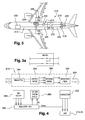
- FIG. 1 represents an aircraft equipped with a device 10 of the prior art for the power supply of an aircraft network 12, in particular for the supply of equipment cockpits and passengers of the aircraft, and a network 14 electric taxing.
- Each network 12, 14 is powered by an electric generator 16, 18 driven by an auxiliary power unit 20, designated by the acronym APU ( Auxiliary Power Unit) in the following.
- APU Auxiliary Power Unit
- the APU 20 is located at the rear of the fuselage of the aircraft and comprises an output shaft (not shown) for driving the rotors of the generators 16, 18.
- the APU 20 is equipped with a starter (not shown ) independent, which is connected to a battery and APU startup control means.
- the generator 16 has an electrical power of 90 kVA and supplies an AC voltage of 115 V to the mains 12, the latter being represented diagrammatically in FIG. figure 1 by a primary distribution box 22 connected by an electrical harness 24 to the generator 16.
- the generator 18 has an electrical power of 120 kVA and supplies an AC voltage of 230 V to the charging network 14, which is schematically represented by four motors (M) 26, connected to an electronic power unit (MCU) of the English Motor Control Unit) 28, which is itself connected by a rectifier 30 to the generator 18.
- the output of the generator 18 is connected to the taxing network 14 by connecting / disconnecting means 32 which isolate the generator of the taxing network 14 when the taxing function is not sought, for example when the aircraft is in flight.
- This electrical architecture has the drawbacks described above, which are mainly due to relatively large electrical power generators 16, 18 (respectively 90kVA and 120kVA), their weight and their size.
- the figure 2 represents an aircraft equipped with another device 110 of the prior art for the power supply of the aircraft network 112 and the taxing network 114.
- the networks 112, 114 are powered by a common electrical generator 116 which is driven by an APU 120.
- the output of the generator 116 is connected to the networks 112, 114 by connecting / disconnecting means 132 and supplies these networks with an alternating voltage Vac2 of 115V.
- the power control unit (MCU) 128 of the taxing network 114 comprises an ATRU module (Auto Transformer Rectifier Unit) for converting energy to increase the voltage level supplied by the generator 116.
- ATRU module Auto Transformer Rectifier Unit
- This other electrical architecture also has drawbacks, which are mainly due to the fact that the ATRU module causes a significant increase in the weight of the electronic power unit (MCU) 128, and that the taxing network 114 must meet all the standards. certification applicable to the aircraft network 112 (ATA type 24).
- the invention overcomes at least some of the disadvantages of the prior art through the power of the taxing network and the network specific to the aircraft by means of two generators, one of which is “hybrid” and allows to feed selectively these two networks.
- the figure 3 represents a preferred embodiment of the device 210 according to the invention, wherein an APU 220, located at the rear of the fuselage of an aircraft, drives the rotors of two independent electric generators 216, 218.
- the output of the generator 216 is connected by connection / disconnection means 232 to the input of a primary distribution box 222 of the aircraft network, the output or outputs of this housing 222 being for example connected to cockpit equipment. and to different compartments of the fuselage of the aircraft.
- the electrical connections between the housing 222, the means 232 and the generator 216 are established by electrical harnesses 224.
- the generator 216 has an electric power of between 30 and 40 kVA and supplies the aircraft network 212 with an alternating voltage Vac2, which is, for example, 115 V to 400 Hz.
- the output of the generator 218 is connected by 232 connection / disconnection means to the input of a rectifier 230 of the taxing network, the output of the rectifier 230 being connected to the input of an electronic power unit (MCU) 228 which powers the motors 226 for driving the wheels of the main landing gear of the aircraft.
- MCU electronic power unit
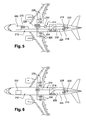
- the means 232 for connection / disconnection of the generators 216, 218 to the networks 212, 214 are formed by a common GNTPCU ( Green Taxiing Power Control Unit) comprising contactors or the like able to establish electrical connections between the generator 218 and the taxing network 214, between the generator 218 and the aircraft network 212, and between the generator 216 and the aircraft network 212.
- the GNTPCU box makes it possible to manage the electrical configurations of the aircraft by means of the contactors and further comprises at least one card type GCU ( Generator Control Unit ) to control the excitation of the generator 218, as will be described in the following.
- the generator 218 has an electrical power of the order of 90kVA for example and is able to feed the taxing network 214 and the aircraft network 212.
- the output of the generator 218 is connected by the means 232 to the aircraft network 212 and supplies to this network an alternating voltage Vac2, which is for example 115v to 400Hz.
- the output of the generator 218 is disconnected from the charging network 214 via the means 232.
- the output of the generator 216 can also be disconnected from the network 212 via means 232.
- the contactors of the GNTPCU box are then in the positions as represented in the figure 3 .
- the output of the generator 216 is connected by the means 232 to the aircraft network 212 and supplies to this network an alternating voltage Vac2, which is, for example, from 115V to 400Hz.
- the output of the generator 218 is connected by the means 232 to the charging network 214 and supplies to this network an alternating voltage Vac1, which is for example 230v to 400Hz, or a power P, which is for example 150kW to 230V.
- the contactors of the GNTPCU box are then in the positions as represented in the figure 3a .
- the rectifier 230 is of the AC / DC type and makes it possible to convert the AC voltage Vac1 into a DC voltage Vdc1.
- the MCU 228 may include contactors and at least one energy converter each having one or more inverters.
- these inverters operate simply in current switching mode when the generator 218 supplies a current or a power to the taxing network 214.
- the generator 216 is preferably a generator / starter (S / G), which can be used in "engine” mode when it is supplied with energy, to start the APU 220. This makes it possible to suppress the starter which was dedicated at the start of the APU in the prior art.
- the low power generator 216 is mounted on the APU 220 in place of the original starter, which does not interfere with the implementation of the generator 218 on the output shaft of the APU 220.
- the generator 218 is used to start the APU 220.
- rotor-excited three-stage stage whose operating principle is schematically represented in FIG. figure 4 .
- the generator 218 comprises a coiled main rotor 250 driven by the APU output shaft 248 within a coiled main stator 252.
- the generator 218 is of the three-stage type (three sets rotor / stator) and comprises in addition to the main rotor assembly 250 / main stator 252, a rotor 254 and a stator 256 with permanent magnets and a rotor 258 and a stator 260 of an exciter, the magnets 254, 258 permanent and the exciter being integral with the output shaft 248 of the APU.
- the output of the rotor 258 of the exciter is connected to the input of a diode rectifier 262, which is integral with the shaft 248, and the output of which is connected to the input of the main rotor 250.
- control and control means 264 comprising at least one GCU card which regulates the current or the voltage of the generator 218 and protects it. case of electrical overload.
- control and control means 264 are also connected to the output of the main stator 252 and comprise means for detecting the voltage or current delivered to the networks 212, 214 of the aircraft.
- the means 264 may be housed in the GNTPCU box.
- the generator 218 can thus operate as follows.
- the output shaft 248 of the APU 220 drives the main rotor 250 of the generator 218 at a predetermined speed.
- the regulation and control means 264 regulate the supply of the stator 260 of the exciter so as to generate a magnetic field inducing a current in the rotor 258 of the exciter, this current leaving the rotor 258 and being rectified by the rectifier 262 before feeding the main rotor 250 to induce a given voltage or current into the main stator 252 of the third stage of the generator.
- the rotor 254 and the stator 256 with permanent magnets make it possible in particular to signal to the means 264 the speed of rotation of the shaft 248.
- the main rotor 250 induces a current or a voltage in the main stator 252 which is intended to supply one or other of the aforementioned networks 212, 214.
- the means 264 control the excitation of the generator 218 as a function of the voltage or current detected at the output of this generator, in such a way that the latter delivers a definite voltage (VAc1 or Vac2) that is substantially constant or possibly variable, in particular to feed the taxing network and is comparable to a voltage generator, or delivers a current that is substantially constant and that is comparable to a voltage. generator of current / power to supply in particular the taxing network.
- the variation of the excitation of the generator 218 makes it possible to switch from a voltage regulation mode Vac2 (for supplying the network 212 to Vac2, for example 115V) to a power regulation mode P (for the power supply of the network 214 in power P, for example 150kW), or a voltage regulation mode Vac2 (for the supply of the network 212 in Vac2, for example 115V) to a voltage regulation mode Vac1 (for supply network 214 voltage Vac1, for example 230V).
- a voltage regulation mode Vac2 for supplying the network 212 to Vac2, for example 115V
- P for the power supply of the network 214 in power P, for example 150kW
- a voltage regulation mode Vac2 for the supply of the network 212 in Vac2, for example 115V
- a voltage regulation mode Vac1 for supply network 214 voltage Vac1, for example 230V
- the generator 218 preferably provides a voltage of 115Vac and a power of 90kVA when connected to the aircraft network, and a power of 150KW when connected to the taxing network.
- an electronic power unit 270 of the SBU type ( Starter Box Unit ) is connected to the harness 224, in parallel with the housing 222.
- This housing 270 is used to control the start of the APU 220 via the generator / starter 216 or 218.
- the control logic of the contactors of the GNTPCU box (means 232) can be adapted accordingly.
- the variant embodiment of the figure 6 differs from that of figure 4 in that the MCU is replaced by an MSCU or MSU 272 ( Motor Starter Unit ) .
- This MSU box 272 integrates a part of the power electronics of the GNTPCU to control the starting of the APU 220 via the generator / starter 216 or 218.
- the electrical starting system of the APU which is used in the present invention can be of the type of that described in the application WO-A2-2010 / 079308 the plaintiff
- the taxing network comprises a number of motors (M) 226 different from four, and for example two.
Landscapes
- Engineering & Computer Science (AREA)
- Aviation & Aerospace Engineering (AREA)
- Power Engineering (AREA)
- Mechanical Engineering (AREA)
- Business, Economics & Management (AREA)
- Emergency Management (AREA)
- Control Of Eletrric Generators (AREA)
- Direct Current Feeding And Distribution (AREA)
- Supply And Distribution Of Alternating Current (AREA)
- Synchronous Machinery (AREA)
- Stand-By Power Supply Arrangements (AREA)
Claims (9)
- Vorrichtung (210) zur elektrischen Versorgung eines Luftfahrzeugs am Boden, enthaltend zwei elektrische Generatoren (216, 218), die über ein Hilfstriebwerk (220) angetrieben werden, wobei der erste Generator dazu bestimmt ist, ein elektrisches Taxiing-Netz (214) zu versorgen, das Elektromotoren (226) zum Antreiben der Räder des Luftfahrzeugs aufweist, wobei der zweite Generator dazu bestimmt ist, ein elektrisches Luftfahrzeug-Netz (21) zu versorgen, dadurch gekennzeichnet, dass der erste Generator über Mittel (232) zum selektiven Verbinden/Trennen mit dem Luftfahrzeug- und dem Taxiing-Netz verbunden ist und dazu geeignet ist, eine erste Wechselspannung Vac2 für das Luftfahrzeug-Netz dann bereitzustellen, wenn er mit diesem Netz verbunden ist, bzw. eine höhere Wechselspannung Vac1 oder eine Leistung P für das Taxiing-Netz dann bereitzustellen, wenn er mit diesen Netz verbunden ist, und dass der zweite Generator über Mittel (232) zum selektiven Verbinden/Trennen mit dem Luftfahrzeug-Netz verbunden ist, um diesem Netz die erste Wechselspannung Vac2 nur dann bereitzustellen, wenn der erste Generator das elektrische Taxiing-Netz des Luftfahrzeugs versorgt.
- Vorrichtung nach Anspruch 1, dadurch gekennzeichnet, dass einer der Generatoren (216, 218) ein Generator/Starter ist, der dazu geeignet ist, das Hilfstriebwerk (220) zu starten.
- Vorrichtung nach Anspruch 2, dadurch gekennzeichnet, dass sie ein elektronisches Leistungsgehäuse (228, 270, 272) aufweist, das mit dem Generator/Starter (216, 218) zum Steuern des Starts des Hilfstriebwerks (220) verbunden ist.
- Vorrichtung nach einem der vorangehenden Ansprüche, dadurch gekennzeichnet, dass der erste Generator (218) ein dreistufiger Synchrongenerator mit Rotorerregerwicklung ist.
- Vorrichtung nach einem der vorangehenden Ansprüche, dadurch gekennzeichnet, dass der erste Generator (218) eine Spannung von 115 Vac (Vac2) bei 400 Hz und eine Leistung von 90 kVA dann bereitstellt, wenn er an das Luftfahrzeug-Netz angeschlossen ist.
- Vorrichtung nach einem der vorangehenden Ansprüche, dadurch gekennzeichnet, dass der erste Generator (218) eine Leistung von 150 kW dann bereitstellt, wenn er an das Taxiing-Netz angeschlossen ist.
- Vorrichtung nach einem der vorangehenden Ansprüche, dadurch gekennzeichnet, dass der zweite Generator (216) eine elektrische Leistung zwischen 30 und 40 kVA und eine Spannung Vac1 von 115Vac bei 400 HZ bereitstellt.
- Verfahren zur elektrischen Versorgung eines Luftfahrzeugs am Boden mittels einer Vorrichtung (210) nach einem der vorangehenden Ansprüche, dadurch gekennzeichnet, dass es einen Schritt umfasst, der darin besteht, das Taxiing-Netz (214) über den ersten Generator (218) und das Luftfahrzeug-Netz (212) über den zweiten Generator (216) zu versorgen, sowie einen Schritt, der darin besteht, das Luftfahrzeug-Netz (212) mittels des ersten Generators (218) dann zu versorgen, wenn die Taxiing-Funktion nicht verwendet wird, wobei der zweite Generator (216) dann außer Betrieb ist.
- Verfahren nach Anspruch 8, dadurch gekennzeichnet, dass der erste Generator (218) ein dreistufiger Synchrongenerator mit Rotorerregerwicklung ist und dass die Erregung dieses Generators über ein elektronisches Leistungsgehäuse (232) gesteuert wird, um von einem Generator der Spannung Vac1 zu einem Generator der Spannung Vac2 oder von einem Generator der Leistung P zu einem Generator der Spannung Vac2 überzugehen.
Applications Claiming Priority (2)
| Application Number | Priority Date | Filing Date | Title |
|---|---|---|---|
| FR1157169A FR2978878B1 (fr) | 2011-08-04 | 2011-08-04 | Dispositif d'alimentation electrique d'un aeronef au sol. |
| PCT/FR2012/051790 WO2013017789A2 (fr) | 2011-08-04 | 2012-07-27 | Dispositif d'alimentation électrique d'un aéronef au sol |
Publications (2)
| Publication Number | Publication Date |
|---|---|
| EP2740191A2 EP2740191A2 (de) | 2014-06-11 |
| EP2740191B1 true EP2740191B1 (de) | 2015-10-07 |
Family
ID=46785751
Family Applications (1)
| Application Number | Title | Priority Date | Filing Date |
|---|---|---|---|
| EP12753762.9A Active EP2740191B1 (de) | 2011-08-04 | 2012-07-27 | Vorrichtung zur versorgung eines flugzeugs am boden mit elektrizität |
Country Status (10)
| Country | Link |
|---|---|
| US (1) | US9592907B2 (de) |
| EP (1) | EP2740191B1 (de) |
| JP (1) | JP5955960B2 (de) |
| CN (1) | CN103703649B (de) |
| BR (1) | BR112014001457B1 (de) |
| CA (1) | CA2842086C (de) |
| ES (1) | ES2554950T3 (de) |
| FR (1) | FR2978878B1 (de) |
| RU (1) | RU2603693C2 (de) |
| WO (1) | WO2013017789A2 (de) |
Families Citing this family (17)
| Publication number | Priority date | Publication date | Assignee | Title |
|---|---|---|---|---|
| FR2988694B1 (fr) * | 2012-03-30 | 2014-03-28 | Hispano Suiza Sa | Dispositif d'alimentation electrique d'un aeronef au sol |
| CN103746448A (zh) * | 2013-12-04 | 2014-04-23 | 中国飞行试验研究院 | 运七飞机供电系统 |
| US20150283908A1 (en) * | 2014-04-02 | 2015-10-08 | Hamilton Sundstrand Corporation | Systems utilizing a controllable voltage ac generator system |
| EP3095988A1 (de) * | 2015-05-18 | 2016-11-23 | Airbus Operations, S.L. | Hilfstriebwerkstartsystem für ein flugzeug |
| GB201511033D0 (en) * | 2015-05-19 | 2015-08-05 | Rolls Royce Plc | Aircraft electrical network |
| US9771149B2 (en) * | 2015-10-30 | 2017-09-26 | Honeywell International Inc. | Gate departure system for aircraft |
| US10518863B2 (en) * | 2016-04-22 | 2019-12-31 | Rolls-Royce Plc | Aircraft electrical network |
| FR3054738B1 (fr) * | 2016-07-29 | 2020-10-23 | Airbus Helicopters | Architecture electrique a double reseau electrique secondaire pour le demarrage des moteurs d'un aeronef |
| GB201715598D0 (en) | 2017-09-27 | 2017-11-08 | Rolls Royce Plc | Electrical interconnect system |
| RU2684971C1 (ru) * | 2017-12-13 | 2019-04-16 | Эйрбас Хеликоптерс | Электрическая система с двойной вторичной электросетью для запуска двигателей летательных аппаратов |
| FR3079820B1 (fr) * | 2018-04-09 | 2020-04-17 | Safran Electrical & Power | Systeme et procede de demarrage/generation pour turbomachine d'aeronef |
| FR3087960B1 (fr) * | 2018-10-31 | 2021-06-04 | Safran | Systeme de conversion et de transport d'energie electrique pour l'hybridation interne d'un aeronef a turboreacteurs |
| US11840356B2 (en) | 2019-03-01 | 2023-12-12 | Hamilton Sundstrand Corporation | Indicators for hybrid electrical powerplants |
| CA3132288A1 (en) | 2019-03-01 | 2020-09-17 | Pratt & Whitney Canada Corp. | Normal mode operation of hybrid electric propulsion systems |
| CA3134499A1 (en) | 2019-04-25 | 2020-10-29 | Pratt & Whitney Canada Corp. | Control systems for hybrid electric powerplants |
| US11958622B2 (en) | 2020-05-15 | 2024-04-16 | Pratt & Whitney Canada Corp. | Protection functions |
| US11794917B2 (en) | 2020-05-15 | 2023-10-24 | Pratt & Whitney Canada Corp. | Parallel control loops for hybrid electric aircraft |
Family Cites Families (21)
| Publication number | Priority date | Publication date | Assignee | Title |
|---|---|---|---|---|
| FR1059612A (fr) | 1952-07-09 | 1954-03-26 | Andre Mathieu Freres | Perfectionnement au montage des plaquettes nasales de lunettes |
| SU868926A1 (ru) * | 1980-01-03 | 1981-09-30 | Предприятие П/Я М-6374 | Устройство дл автоматического переключени потребителей с одного канала питани посто нного тока на другой |
| JPH0214415U (de) * | 1988-07-13 | 1990-01-30 | ||
| US5899411A (en) * | 1996-01-22 | 1999-05-04 | Sundstrand Corporation | Aircraft electrical system providing emergency power and electric starting of propulsion engines |
| US7210653B2 (en) * | 2002-10-22 | 2007-05-01 | The Boeing Company | Electric-based secondary power system architectures for aircraft |
| RU2232109C1 (ru) * | 2003-09-22 | 2004-07-10 | ОАО "ОКБ им. А.С.Яковлева" | Способ электроснабжения бортовых систем летательного аппарата |
| JP4725010B2 (ja) * | 2003-10-31 | 2011-07-13 | シンフォニアテクノロジー株式会社 | 2系統相互バックアップ式電源装置 |
| JP2005354861A (ja) * | 2004-06-14 | 2005-12-22 | Fuji Electric Systems Co Ltd | 原動機駆動電源装置による給電装置 |
| US7439634B2 (en) * | 2004-08-24 | 2008-10-21 | Honeywell International Inc. | Electrical starting, generation, conversion and distribution system architecture for a more electric vehicle |
| US7445178B2 (en) * | 2004-09-28 | 2008-11-04 | The Boeing Company | Powered nose aircraft wheel system |
| US7975960B2 (en) * | 2005-08-29 | 2011-07-12 | Borealis Technical Limited | Nosewheel control apparatus |
| US8155876B2 (en) | 2006-09-07 | 2012-04-10 | The Boeing Company | Systems and methods for controlling aircraft electrical power |
| FR2907762B1 (fr) * | 2006-10-27 | 2009-12-18 | Airbus France | Systeme de generation, conversion, distribution et demarrage electrique a bord d'un aeronef |
| FR2911848B1 (fr) * | 2007-01-31 | 2009-12-25 | Hispano Suiza Sa | Circuit d'alimentation en energie electrique dans un aeronef pour des equipements electriques comprenant un circuit de degivrage |
| FR2930084B1 (fr) * | 2008-04-09 | 2012-06-08 | Thales Sa | Procede de gestion d'un reseau electrique |
| FR2941107B1 (fr) | 2009-01-09 | 2015-08-14 | Hispano Suiza Sa | Systeme electrique de demarrage des moteurs d'un aeronef |
| GB0905568D0 (en) * | 2009-04-01 | 2009-05-13 | Rolls Royce Plc | Taxling |
| FR2944775B1 (fr) * | 2009-04-24 | 2013-03-08 | Messier Bugatti | Procede de deplacement d'un aeronef au sol |
| FR2954283B1 (fr) * | 2009-12-23 | 2012-03-02 | Hispano Suiza Sa | Aeronef comportant un demarreur-generateur electrique pour le ou chaque turboreacteur et un train d'aterrissage equipe d'un moteur electrique de manoeuvre au sol |
| FR2960520B1 (fr) * | 2010-05-26 | 2012-06-29 | Airbus Operations Sas | Aeronef comprenant un moteur de train |
| FR2975376B1 (fr) * | 2011-05-20 | 2018-03-30 | Safran Landing Systems | Procede pour alimenter des moteurs de deplacement autonome d'un aeronef. |
-
2011
- 2011-08-04 FR FR1157169A patent/FR2978878B1/fr active Active
-
2012
- 2012-07-27 JP JP2014523366A patent/JP5955960B2/ja active Active
- 2012-07-27 CA CA2842086A patent/CA2842086C/fr active Active
- 2012-07-27 RU RU2014108158/07A patent/RU2603693C2/ru active
- 2012-07-27 WO PCT/FR2012/051790 patent/WO2013017789A2/fr active Application Filing
- 2012-07-27 EP EP12753762.9A patent/EP2740191B1/de active Active
- 2012-07-27 US US14/234,541 patent/US9592907B2/en active Active
- 2012-07-27 CN CN201280035443.3A patent/CN103703649B/zh active Active
- 2012-07-27 ES ES12753762.9T patent/ES2554950T3/es active Active
- 2012-07-27 BR BR112014001457-4A patent/BR112014001457B1/pt active IP Right Grant
Also Published As
| Publication number | Publication date |
|---|---|
| RU2014108158A (ru) | 2015-09-10 |
| FR2978878A1 (fr) | 2013-02-08 |
| WO2013017789A3 (fr) | 2013-10-24 |
| CA2842086A1 (fr) | 2013-02-07 |
| BR112014001457B1 (pt) | 2021-05-25 |
| CA2842086C (fr) | 2019-05-14 |
| JP2014525873A (ja) | 2014-10-02 |
| JP5955960B2 (ja) | 2016-07-20 |
| FR2978878B1 (fr) | 2013-08-09 |
| EP2740191A2 (de) | 2014-06-11 |
| CN103703649A (zh) | 2014-04-02 |
| CN103703649B (zh) | 2016-08-31 |
| US9592907B2 (en) | 2017-03-14 |
| RU2603693C2 (ru) | 2016-11-27 |
| WO2013017789A2 (fr) | 2013-02-07 |
| BR112014001457A2 (pt) | 2018-08-14 |
| US20140138479A1 (en) | 2014-05-22 |
| ES2554950T3 (es) | 2015-12-28 |
Similar Documents
| Publication | Publication Date | Title |
|---|---|---|
| EP2740191B1 (de) | Vorrichtung zur versorgung eines flugzeugs am boden mit elektrizität | |
| EP2830938B1 (de) | Stromversorgung für ein fluzeug am boden | |
| CA2667270C (fr) | Systeme de generation, conversion, distribution et demarrage electrique a bord d'un aeronef | |
| CA2872724C (fr) | Systeme de commande et d'alimentation en energie des turbomachines d'un helicoptere | |
| EP1953085B1 (de) | Stromversorgungsschaltkreis in einem Luftfahrzeug für die elektrischen Geräte einschließlich Enteisungsschaltkreis | |
| EP1849225B1 (de) | Stromversorgung für eine gasturbinentriebwerkanlage für luftfahrzeuge | |
| EP3588729B1 (de) | Elektrische architektur für luftfahrzeug, diese architektur umfassendes luftfahrzeug und funktionsverfahren der architektur | |
| CA2893436C (fr) | Procede de gestion du reseau d'alimentation electrique d'un aeronef | |
| FR2966804A1 (fr) | Aerodyne comprenant des trains d'atterrissage motorises | |
| CA2750092A1 (fr) | Locomotive diesel-electrique | |
| EP1515426A1 (de) | Elektrizitätserzeugungssystem mit fester Frequenz und Verfahren zur Steuerung desselben | |
| JP6542795B2 (ja) | タービンエンジンの急速再活性化の方法及びシステム | |
| EP2951904B1 (de) | Verfahren und system zur versorgung eines flugzeugs mit elektrischer energie | |
| FR2962407A1 (fr) | Alimentation d'equipements electriques d'un aeronef | |
| FR2944260A1 (fr) | Systeme de generation de puissance electrique pour aeronef a propulsion arriere | |
| WO2023281210A1 (fr) | Architecture de génération électrique pour turbomachine hybridée | |
| FR2944259A1 (fr) | Systeme de generation de puissance electrique pour aeronef a propulsion arriere |
Legal Events
| Date | Code | Title | Description |
|---|---|---|---|
| PUAI | Public reference made under article 153(3) epc to a published international application that has entered the european phase |
Free format text: ORIGINAL CODE: 0009012 |
|
| 17P | Request for examination filed |
Effective date: 20140110 |
|
| AK | Designated contracting states |
Kind code of ref document: A2 Designated state(s): AL AT BE BG CH CY CZ DE DK EE ES FI FR GB GR HR HU IE IS IT LI LT LU LV MC MK MT NL NO PL PT RO RS SE SI SK SM TR |
|
| DAX | Request for extension of the european patent (deleted) | ||
| RAP1 | Party data changed (applicant data changed or rights of an application transferred) |
Owner name: LABINAL POWER SYSTEMS Owner name: TURBOMECA |
|
| GRAP | Despatch of communication of intention to grant a patent |
Free format text: ORIGINAL CODE: EPIDOSNIGR1 |
|
| INTG | Intention to grant announced |
Effective date: 20150428 |
|
| GRAS | Grant fee paid |
Free format text: ORIGINAL CODE: EPIDOSNIGR3 |
|
| GRAA | (expected) grant |
Free format text: ORIGINAL CODE: 0009210 |
|
| AK | Designated contracting states |
Kind code of ref document: B1 Designated state(s): AL AT BE BG CH CY CZ DE DK EE ES FI FR GB GR HR HU IE IS IT LI LT LU LV MC MK MT NL NO PL PT RO RS SE SI SK SM TR |
|
| REG | Reference to a national code |
Ref country code: GB Ref legal event code: FG4D Free format text: NOT ENGLISH |
|
| REG | Reference to a national code |
Ref country code: AT Ref legal event code: REF Ref document number: 754253 Country of ref document: AT Kind code of ref document: T Effective date: 20151015 Ref country code: CH Ref legal event code: EP |
|
| REG | Reference to a national code |
Ref country code: IE Ref legal event code: FG4D Free format text: LANGUAGE OF EP DOCUMENT: FRENCH |
|
| REG | Reference to a national code |
Ref country code: DE Ref legal event code: R096 Ref document number: 602012011368 Country of ref document: DE |
|
| REG | Reference to a national code |
Ref country code: ES Ref legal event code: FG2A Ref document number: 2554950 Country of ref document: ES Kind code of ref document: T3 Effective date: 20151228 |
|
| REG | Reference to a national code |
Ref country code: NL Ref legal event code: MP Effective date: 20151007 |
|
| REG | Reference to a national code |
Ref country code: AT Ref legal event code: MK05 Ref document number: 754253 Country of ref document: AT Kind code of ref document: T Effective date: 20151007 |
|
| REG | Reference to a national code |
Ref country code: LT Ref legal event code: MG4D |
|
| PG25 | Lapsed in a contracting state [announced via postgrant information from national office to epo] |
Ref country code: HR Free format text: LAPSE BECAUSE OF FAILURE TO SUBMIT A TRANSLATION OF THE DESCRIPTION OR TO PAY THE FEE WITHIN THE PRESCRIBED TIME-LIMIT Effective date: 20151007 Ref country code: IS Free format text: LAPSE BECAUSE OF FAILURE TO SUBMIT A TRANSLATION OF THE DESCRIPTION OR TO PAY THE FEE WITHIN THE PRESCRIBED TIME-LIMIT Effective date: 20160207 Ref country code: NL Free format text: LAPSE BECAUSE OF FAILURE TO SUBMIT A TRANSLATION OF THE DESCRIPTION OR TO PAY THE FEE WITHIN THE PRESCRIBED TIME-LIMIT Effective date: 20151007 Ref country code: LT Free format text: LAPSE BECAUSE OF FAILURE TO SUBMIT A TRANSLATION OF THE DESCRIPTION OR TO PAY THE FEE WITHIN THE PRESCRIBED TIME-LIMIT Effective date: 20151007 Ref country code: NO Free format text: LAPSE BECAUSE OF FAILURE TO SUBMIT A TRANSLATION OF THE DESCRIPTION OR TO PAY THE FEE WITHIN THE PRESCRIBED TIME-LIMIT Effective date: 20160107 Ref country code: IT Free format text: LAPSE BECAUSE OF FAILURE TO SUBMIT A TRANSLATION OF THE DESCRIPTION OR TO PAY THE FEE WITHIN THE PRESCRIBED TIME-LIMIT Effective date: 20151007 |
|
| PG25 | Lapsed in a contracting state [announced via postgrant information from national office to epo] |
Ref country code: PT Free format text: LAPSE BECAUSE OF FAILURE TO SUBMIT A TRANSLATION OF THE DESCRIPTION OR TO PAY THE FEE WITHIN THE PRESCRIBED TIME-LIMIT Effective date: 20160208 Ref country code: PL Free format text: LAPSE BECAUSE OF FAILURE TO SUBMIT A TRANSLATION OF THE DESCRIPTION OR TO PAY THE FEE WITHIN THE PRESCRIBED TIME-LIMIT Effective date: 20151007 Ref country code: GR Free format text: LAPSE BECAUSE OF FAILURE TO SUBMIT A TRANSLATION OF THE DESCRIPTION OR TO PAY THE FEE WITHIN THE PRESCRIBED TIME-LIMIT Effective date: 20160108 Ref country code: RS Free format text: LAPSE BECAUSE OF FAILURE TO SUBMIT A TRANSLATION OF THE DESCRIPTION OR TO PAY THE FEE WITHIN THE PRESCRIBED TIME-LIMIT Effective date: 20151007 Ref country code: FI Free format text: LAPSE BECAUSE OF FAILURE TO SUBMIT A TRANSLATION OF THE DESCRIPTION OR TO PAY THE FEE WITHIN THE PRESCRIBED TIME-LIMIT Effective date: 20151007 Ref country code: SE Free format text: LAPSE BECAUSE OF FAILURE TO SUBMIT A TRANSLATION OF THE DESCRIPTION OR TO PAY THE FEE WITHIN THE PRESCRIBED TIME-LIMIT Effective date: 20151007 Ref country code: LV Free format text: LAPSE BECAUSE OF FAILURE TO SUBMIT A TRANSLATION OF THE DESCRIPTION OR TO PAY THE FEE WITHIN THE PRESCRIBED TIME-LIMIT Effective date: 20151007 Ref country code: AT Free format text: LAPSE BECAUSE OF FAILURE TO SUBMIT A TRANSLATION OF THE DESCRIPTION OR TO PAY THE FEE WITHIN THE PRESCRIBED TIME-LIMIT Effective date: 20151007 |
|
| REG | Reference to a national code |
Ref country code: FR Ref legal event code: PLFP Year of fee payment: 5 |
|
| REG | Reference to a national code |
Ref country code: DE Ref legal event code: R097 Ref document number: 602012011368 Country of ref document: DE |
|
| PG25 | Lapsed in a contracting state [announced via postgrant information from national office to epo] |
Ref country code: CZ Free format text: LAPSE BECAUSE OF FAILURE TO SUBMIT A TRANSLATION OF THE DESCRIPTION OR TO PAY THE FEE WITHIN THE PRESCRIBED TIME-LIMIT Effective date: 20151007 |
|
| PLBE | No opposition filed within time limit |
Free format text: ORIGINAL CODE: 0009261 |
|
| STAA | Information on the status of an ep patent application or granted ep patent |
Free format text: STATUS: NO OPPOSITION FILED WITHIN TIME LIMIT |
|
| PG25 | Lapsed in a contracting state [announced via postgrant information from national office to epo] |
Ref country code: SM Free format text: LAPSE BECAUSE OF FAILURE TO SUBMIT A TRANSLATION OF THE DESCRIPTION OR TO PAY THE FEE WITHIN THE PRESCRIBED TIME-LIMIT Effective date: 20151007 Ref country code: SK Free format text: LAPSE BECAUSE OF FAILURE TO SUBMIT A TRANSLATION OF THE DESCRIPTION OR TO PAY THE FEE WITHIN THE PRESCRIBED TIME-LIMIT Effective date: 20151007 Ref country code: DK Free format text: LAPSE BECAUSE OF FAILURE TO SUBMIT A TRANSLATION OF THE DESCRIPTION OR TO PAY THE FEE WITHIN THE PRESCRIBED TIME-LIMIT Effective date: 20151007 Ref country code: RO Free format text: LAPSE BECAUSE OF FAILURE TO SUBMIT A TRANSLATION OF THE DESCRIPTION OR TO PAY THE FEE WITHIN THE PRESCRIBED TIME-LIMIT Effective date: 20151007 Ref country code: EE Free format text: LAPSE BECAUSE OF FAILURE TO SUBMIT A TRANSLATION OF THE DESCRIPTION OR TO PAY THE FEE WITHIN THE PRESCRIBED TIME-LIMIT Effective date: 20151007 |
|
| 26N | No opposition filed |
Effective date: 20160708 |
|
| PG25 | Lapsed in a contracting state [announced via postgrant information from national office to epo] |
Ref country code: SI Free format text: LAPSE BECAUSE OF FAILURE TO SUBMIT A TRANSLATION OF THE DESCRIPTION OR TO PAY THE FEE WITHIN THE PRESCRIBED TIME-LIMIT Effective date: 20151007 |
|
| PG25 | Lapsed in a contracting state [announced via postgrant information from national office to epo] |
Ref country code: BE Free format text: LAPSE BECAUSE OF NON-PAYMENT OF DUE FEES Effective date: 20160731 |
|
| REG | Reference to a national code |
Ref country code: DE Ref legal event code: R119 Ref document number: 602012011368 Country of ref document: DE |
|
| REG | Reference to a national code |
Ref country code: CH Ref legal event code: PL |
|
| PG25 | Lapsed in a contracting state [announced via postgrant information from national office to epo] |
Ref country code: MC Free format text: LAPSE BECAUSE OF FAILURE TO SUBMIT A TRANSLATION OF THE DESCRIPTION OR TO PAY THE FEE WITHIN THE PRESCRIBED TIME-LIMIT Effective date: 20151007 |
|
| REG | Reference to a national code |
Ref country code: FR Ref legal event code: PLFP Year of fee payment: 6 |
|
| PG25 | Lapsed in a contracting state [announced via postgrant information from national office to epo] |
Ref country code: CH Free format text: LAPSE BECAUSE OF NON-PAYMENT OF DUE FEES Effective date: 20160731 Ref country code: DE Free format text: LAPSE BECAUSE OF NON-PAYMENT OF DUE FEES Effective date: 20170201 Ref country code: LI Free format text: LAPSE BECAUSE OF NON-PAYMENT OF DUE FEES Effective date: 20160731 |
|
| REG | Reference to a national code |
Ref country code: IE Ref legal event code: MM4A |
|
| PG25 | Lapsed in a contracting state [announced via postgrant information from national office to epo] |
Ref country code: IE Free format text: LAPSE BECAUSE OF NON-PAYMENT OF DUE FEES Effective date: 20160727 |
|
| PG25 | Lapsed in a contracting state [announced via postgrant information from national office to epo] |
Ref country code: LU Free format text: LAPSE BECAUSE OF NON-PAYMENT OF DUE FEES Effective date: 20160727 |
|
| REG | Reference to a national code |
Ref country code: FR Ref legal event code: CD Owner name: SAFRAN HELICOPTER ENGINES, FR Effective date: 20170727 Ref country code: FR Ref legal event code: CD Owner name: LABINAL POWER SYSTEMS, FR Effective date: 20170727 |
|
| REG | Reference to a national code |
Ref country code: FR Ref legal event code: CA Effective date: 20171002 |
|
| REG | Reference to a national code |
Ref country code: FR Ref legal event code: CA Effective date: 20171218 Ref country code: FR Ref legal event code: CD Owner name: SAFRAN HELICOPTER ENGINES, FR Effective date: 20171218 Ref country code: FR Ref legal event code: CD Owner name: SAFRAN ELECTRICAL & POWER, FR Effective date: 20171218 |
|
| PG25 | Lapsed in a contracting state [announced via postgrant information from national office to epo] |
Ref country code: HU Free format text: LAPSE BECAUSE OF FAILURE TO SUBMIT A TRANSLATION OF THE DESCRIPTION OR TO PAY THE FEE WITHIN THE PRESCRIBED TIME-LIMIT; INVALID AB INITIO Effective date: 20120727 Ref country code: CY Free format text: LAPSE BECAUSE OF FAILURE TO SUBMIT A TRANSLATION OF THE DESCRIPTION OR TO PAY THE FEE WITHIN THE PRESCRIBED TIME-LIMIT Effective date: 20151007 |
|
| REG | Reference to a national code |
Ref country code: FR Ref legal event code: PLFP Year of fee payment: 7 |
|
| PG25 | Lapsed in a contracting state [announced via postgrant information from national office to epo] |
Ref country code: MT Free format text: LAPSE BECAUSE OF FAILURE TO SUBMIT A TRANSLATION OF THE DESCRIPTION OR TO PAY THE FEE WITHIN THE PRESCRIBED TIME-LIMIT Effective date: 20151007 Ref country code: MK Free format text: LAPSE BECAUSE OF FAILURE TO SUBMIT A TRANSLATION OF THE DESCRIPTION OR TO PAY THE FEE WITHIN THE PRESCRIBED TIME-LIMIT Effective date: 20151007 |
|
| PG25 | Lapsed in a contracting state [announced via postgrant information from national office to epo] |
Ref country code: BG Free format text: LAPSE BECAUSE OF FAILURE TO SUBMIT A TRANSLATION OF THE DESCRIPTION OR TO PAY THE FEE WITHIN THE PRESCRIBED TIME-LIMIT Effective date: 20151007 |
|
| PG25 | Lapsed in a contracting state [announced via postgrant information from national office to epo] |
Ref country code: AL Free format text: LAPSE BECAUSE OF FAILURE TO SUBMIT A TRANSLATION OF THE DESCRIPTION OR TO PAY THE FEE WITHIN THE PRESCRIBED TIME-LIMIT Effective date: 20151007 Ref country code: TR Free format text: LAPSE BECAUSE OF FAILURE TO SUBMIT A TRANSLATION OF THE DESCRIPTION OR TO PAY THE FEE WITHIN THE PRESCRIBED TIME-LIMIT Effective date: 20151007 |
|
| PGFP | Annual fee paid to national office [announced via postgrant information from national office to epo] |
Ref country code: FR Payment date: 20230621 Year of fee payment: 12 |
|
| PGFP | Annual fee paid to national office [announced via postgrant information from national office to epo] |
Ref country code: GB Payment date: 20230620 Year of fee payment: 12 Ref country code: ES Payment date: 20230801 Year of fee payment: 12 |