EP2739343B1 - Implant system including guiding accessory - Google Patents
Implant system including guiding accessory Download PDFInfo
- Publication number
- EP2739343B1 EP2739343B1 EP12745753.9A EP12745753A EP2739343B1 EP 2739343 B1 EP2739343 B1 EP 2739343B1 EP 12745753 A EP12745753 A EP 12745753A EP 2739343 B1 EP2739343 B1 EP 2739343B1
- Authority
- EP
- European Patent Office
- Prior art keywords
- lumen
- catheter
- wall
- distal portion
- conductor
- Prior art date
- Legal status (The legal status is an assumption and is not a legal conclusion. Google has not performed a legal analysis and makes no representation as to the accuracy of the status listed.)
- Not-in-force
Links
Images


Classifications
-
- A—HUMAN NECESSITIES
- A61—MEDICAL OR VETERINARY SCIENCE; HYGIENE
- A61N—ELECTROTHERAPY; MAGNETOTHERAPY; RADIATION THERAPY; ULTRASOUND THERAPY
- A61N1/00—Electrotherapy; Circuits therefor
- A61N1/02—Details
- A61N1/04—Electrodes
- A61N1/05—Electrodes for implantation or insertion into the body, e.g. heart electrode
- A61N1/056—Transvascular endocardial electrode systems
-
- A—HUMAN NECESSITIES
- A61—MEDICAL OR VETERINARY SCIENCE; HYGIENE
- A61N—ELECTROTHERAPY; MAGNETOTHERAPY; RADIATION THERAPY; ULTRASOUND THERAPY
- A61N1/00—Electrotherapy; Circuits therefor
- A61N1/18—Applying electric currents by contact electrodes
- A61N1/32—Applying electric currents by contact electrodes alternating or intermittent currents
- A61N1/36—Applying electric currents by contact electrodes alternating or intermittent currents for stimulation
- A61N1/372—Arrangements in connection with the implantation of stimulators
- A61N1/37205—Microstimulators, e.g. implantable through a cannula
-
- A—HUMAN NECESSITIES
- A61—MEDICAL OR VETERINARY SCIENCE; HYGIENE
- A61N—ELECTROTHERAPY; MAGNETOTHERAPY; RADIATION THERAPY; ULTRASOUND THERAPY
- A61N1/00—Electrotherapy; Circuits therefor
- A61N1/18—Applying electric currents by contact electrodes
- A61N1/32—Applying electric currents by contact electrodes alternating or intermittent currents
- A61N1/36—Applying electric currents by contact electrodes alternating or intermittent currents for stimulation
- A61N1/372—Arrangements in connection with the implantation of stimulators
- A61N1/375—Constructional arrangements, e.g. casings
- A61N1/3756—Casings with electrodes thereon, e.g. leadless stimulators
Definitions
- the present invention pertains to systems for implanting therapy delivery devices and more particularly to guiding accessories of the systems.
- the traditional implantable cardiac pacemaker includes a pulse generator device to which one or more flexible elongate lead wires are coupled.
- the device is typically implanted in a subcutaneous pocket, remote from the heart, and each of the one or more lead wires extends therefrom to a corresponding electrode, coupled thereto and positioned at a pacing site, either endocardial or epicardial.
- Mechanical complications and/or MRI compatibility issues which are sometimes associated with elongate lead wires and well known to those skilled in the art, have motivated the development of cardiac pacing devices that are wholly contained within a relatively compact package for implant in close proximity to the pacing site, for example, within the right ventricle (RV) of the heart.
- RV right ventricle
- pace/sense electrodes 111, 112 are formed on an exterior surface of a shell 101 that hermetically contains a pulse generator including pulse generator electronics and a power source.
- Shell 101 is preferably formed from a biocompatible and biostable metal such as titanium overlaid with an insulative layer, for example, medical grade polyurethane or silicone, except where electrode 112 is formed as an exposed portion of capsule 101.
- a hermetic feedthrough assembly (not shown), such as any known to those skilled in the art, couples electrode 111 to the pulse generator contained within shell 101.
- Figure 1 further illustrates a fixation member 115 mounted to an end of shell 101, in proximity to electrode 111, in order to fix, or secure electrode 111 against the endocardial surface in the apex of the RV.
- pacing stimulation may be more effective if delivered to a right atrial site or a left ventricular site.
- alternative forms of relatively compact pacing devices have been developed for these alternate implant sites and there is a need for corresponding implant systems and methods.
- US 2004/0059404 shows a system and method for maintaining a medical lead at a site of implant using a deployable fixation mechanism.
- Embodiments of the present invention facilitate the implant of a type of relatively compact therapy delivery device which includes an elongate and flexible isolated conductor extending from a therapy generator of the device.
- a system comprising a guidewire, a catheter and a guiding accessory for implanting a therapy delivery device is provided by claim 1.
- Methods employ a guiding accessory in conjunction with a catheter and guidewire to facilitate passage of the conductor to an implant site, for example, into the cardiac venous system via an ostium of the coronary sinus, when the therapy generator of the device is held within a distal portion of the catheter.
- the guiding accessory includes a helically extending wall that forms a lumen within which the conductor of the device can extend, when the generator is held within the distal portion of the catheter.
- the catheter includes a lumen, preferably extending alongside the distal portion, for guidewire passage; and the lumen of the guiding accessory also allows passage of the guidewire, alongside the conductor of the device, so that the catheter and guiding accessory, along with the device, may be advanced along the guidewire to an implant site.
- the helically extending wall of the guiding accessory is removed from around the conductor of the device, preferably, by pulling proximally on a tension line, which is attached to a proximal end of the helically extending wall, to draw the wall toward the distal portion of the catheter, thereby unwinding the wall from around the conductor.
- Figure 2A is a plan view of an exemplary implantable therapy delivery device 200 for which implant methods and systems of the present invention are suitable.
- Figure 2A illustrates device 200 including a therapy generator 210, a fixation member 215 coupled thereto, and a therapy delivery element 213 coupled to generator 210 via an elongate and flexible isolated conductor 230.
- Device 200 is preferably sized to be wholly implanted at a cardiac site, wherein exemplary dimensions are as follows: a length of generator 210 is between approximately 20 mm and approximately 25 mm; a diameter of generator 210 is between approximately 5 mm and approximately 7 mm; a length of conductor 230 is preferably between approximately 20 mm and approximately 80 mm; and a diameter of conductor 230 is preferably between approximately 0.025 inch (0.6 mm) and approximately 0.035 inch (0.9 mm).
- Device 200 may be adapted to deliver any type of suitable therapy, for example, device 200 may be similar to the above-described device 100 wherein generator 210 is a pacing pulse generator contained in a hermetic enclosure/shell, and therapy delivery element 213 is an electrode, albeit one that is offset from generator 210 by the length of conductor 230. With reference to Figures 2B-C , alternate implant sites for device 200, which are facilitated by the length of conductor 230, are shown.
- Figure 2B is an anterior view of a heart in which a portion of a right atrial wall is cut away; and Figure 2C is a posterior view of the heart in which a portion of the coronary venous system is cut away.
- Figure 2B illustrates generator 210 fixed in proximity to a coronary sinus ostium CSos within the right atrium RA, so that conductor 230 extends into ostium CSos for positioning of therapy delivery element 213 (not shown) within the coronary sinus CS, or upstream thereof, in another vein, if the length of conductor 230 allows.
- Figure 2C illustrates the coronary sinus CS and a first coronary vein CV1 extending distally therefrom.
- generator 210 is shown fixed within a proximal portion of the coronary sinus CS, and conductor 230 is shown extending from the coronary sinus CS so that delivery element 213 is located within vein CV1.
- delivery element 213 is an electrode
- the illustrated position for implant may be suitable for left ventricular pacing; alternately, for this same purpose, delivery element 213 may be positioned within any of the other coronary veins CV2, CV3, CV4 ( Figure 2B ).
- an implant system such as a system 600 shown in subsequent Figures, includes a guiding accessory 500 to facilitate delivery of device 200 to any the above-described implant locations.
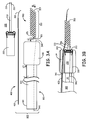
- Figure 3A is a plan view of implant system 600; and Figure 3B is a plan view of a distal portion of implant system 600 with a cut-away section.
- Figure 3A illustrates device 200 alongside implant system 600, and implant system 600 including a catheter 300, a guidewire 400 and guiding accessory 500.
- Guidewire 400 may be any suitable type known to those skilled in the art of interventional cardiology and electrophysiology, preferably having a diameter, in proximity to a distal tip 403 thereof, of between 0.010 inch and 0.018 inch (0.254 - 0.4572 mm); and catheter 300 may be constructed with a fixed shape distal segment or a steerable distal segment according to construction methods known in the art.
- Catheter 300 is shown including an elongate shaft 320 extending from a proximal end 301 of catheter 300 to a distal portion 330 of catheter 300.
- Figure 3B illustrates a lumen 30 of catheter shaft 320 opening into an interior of distal portion 330, which interior holds generator 210 of device 200.
- lumen 30 extends to proximal end 301 of catheter 300.
- Figure 3B further illustrates catheter 300 including a guidewire lumen 34, which, preferably, only extends approximately along a length of distal portion 330.
- guidewire lumen 34 may extend further proximally, along catheter shaft 320, or may extend within catheter shaft 320, alongside lumen 30, and open into the interior of distal portion 330.
- Figures 3A-B further illustrate guiding accessory 500 including a helically extending wall 550 and a tension line 540 attached to wall 550; tension line 540 extends proximally from wall 550 and into distal portion 330 of catheter 300, then along a length of catheter shaft 320 and out proximal end 301 of catheter 300.
- Tension line 540 is preferably formed from a relatively high tensile strength polymer fiber, such as polyester, which is attached, for example, by tying with a knot to a proximal end 501 of wall 550.
- tension line 540 is preferably accommodated within lumen 30 along the length of shaft 320.
- lumen 30 may accommodate both tension line 540 and guidewire 400, so that lumen 34 is not necessary.
- generator 210 of device 200 may be loaded into distal portion 330 of catheter 300, through a distal opening thereof, per arrow L1, and a distal end 203 of elongate and flexible isolated conductor 230 may be loaded into a lumen 55 ( Figure 4 ), which is formed by helically extending wall 550 of guiding accessory 500, through a proximal opening 551 thereof, per arrow L2.
- guidewire 400 may be loaded into lumen 34 of catheter and into lumen 55 of guiding accessory 500, for example, per arrows L3 and L2, respectively.
- lumen 55 has a diameter sized to accommodate therein guidewire 400 and conductor 230 of device 200, side-by-side, as shown in Figures 3B and 4 ; and guidewire 400 is slidable alongside conductor 230 within lumen 55. Furthermore, the size of lumen 55 allows helically extending wall 550 and conductor 230 to move together along guidewire 400.
- Helically extending wall 550 may be formed from a coiled strip of one or a combination of a resilient biocompatible polymer and a resilient biocompatible metal, wherein the strip preferably has a rectangular cross-section or a round cross-section. Alternately, wall 550 may be formed from a spiral cut polymer tube.
- a thickness of wall 550 is preferably between approximately 0.007 inch (0.2 mm) and approximately 0.02 inch (0.5 mm), according to some embodiments. Adjacent turns of wall 550 are separable from one another so that, when a pull force is applied, for example, to proximal end 501, via tension line 540, wall 550 unwinds, as will be described in greater detail below.
- catheter 300 and guiding accessory 500 are advanced along guidewire 400 to the implant site, for example, as illustrated in Figure 4 .
- guidewire 400 is advanced transvenously to the implant site, independent of catheter 300, device 200 and accessory 500, and then proximal end 401 of guidewire 400 is back-loaded, per arrow BL ( Figure 3A ), into guiding accessory lumen 55, via a distal opening 553 thereof, and then into guidewire lumen 34, via a distal opening 343 thereof ( Figure 3B ), and then out a proximal opening 341 of guidewire lumen 34, before catheter 300, accessory 500 and loaded device 200 are advanced thereover to the implant site.
- guiding accessory 500 is useful in holding conductor 230 alongside guidewire 400 to facilitate passage of conductor 230 into the coronary sinus CS and, if necessary (dependent upon the target site for therapy delivery element 213 of device 200), upstream to one of veins, for example, CV1, CV2, CV3 or CV4.
- guiding accessory 500 is removed by drawing a proximal end 501 of helically extending wall 550 toward distal opening 333 of distal portion 330 and proximally therefrom, per arrow D of Figure 4 , thereby unwinding wall 550 from around conductor 230 of device 200, for example, as shown in Figure 5 .
- tension line 540 of guiding accessory 500 is employed to unwind helically extending wall 550, by applying a pull force, for example, from a proximal end 541 of line 540, per arrow P; the unwound wall 550 is subsequently drawn into the same lumen 30 that accommodates tension line 540.
- other means may be employed to draw in proximal end 501 of wall 550 per arrow D, thereby unwinding wall 550 from around conductor 230; for example, a hooked wire or opposing jaws may be deployed from catheter 300 to engage proximal end 501 of wall 550 and draw it into catheter 300.
- dashed lines show an optional push member that may be used to push generator 210 out from distal portion 330 of catheter just prior to, or, preferably, in conjunction with, drawing proximal end 501 of helically extending wall 550 in, per arrow D.
- guidewire 400 may remain within both lumens 34, 55 while wall 550 of guiding accessory 500 is unwound and removed, or guidewire 400 may be pulled out from lumen 55, but remain in lumen 34, while wall 550 is unwound and removed.
Description
- The present invention pertains to systems for implanting therapy delivery devices and more particularly to guiding accessories of the systems.
- The traditional implantable cardiac pacemaker includes a pulse generator device to which one or more flexible elongate lead wires are coupled. The device is typically implanted in a subcutaneous pocket, remote from the heart, and each of the one or more lead wires extends therefrom to a corresponding electrode, coupled thereto and positioned at a pacing site, either endocardial or epicardial. Mechanical complications and/or MRI compatibility issues, which are sometimes associated with elongate lead wires and well known to those skilled in the art, have motivated the development of cardiac pacing devices that are wholly contained within a relatively compact package for implant in close proximity to the pacing site, for example, within the right ventricle (RV) of the heart. With reference to
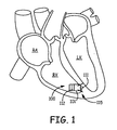
Figure 1 , such adevice 100 is illustrated, wherein pace/sense electrodes shell 101 that hermetically contains a pulse generator including pulse generator electronics and a power source. Shell 101 is preferably formed from a biocompatible and biostable metal such as titanium overlaid with an insulative layer, for example, medical grade polyurethane or silicone, except whereelectrode 112 is formed as an exposed portion ofcapsule 101. A hermetic feedthrough assembly (not shown), such as any known to those skilled in the art,couples electrode 111 to the pulse generator contained withinshell 101. -
Figure 1 further illustrates afixation member 115 mounted to an end ofshell 101, in proximity toelectrode 111, in order to fix, or secureelectrode 111 against the endocardial surface in the apex of the RV. However, in some patients, pacing stimulation may be more effective if delivered to a right atrial site or a left ventricular site. Thus, alternative forms of relatively compact pacing devices have been developed for these alternate implant sites and there is a need for corresponding implant systems and methods. -
US 2004/0059404 shows a system and method for maintaining a medical lead at a site of implant using a deployable fixation mechanism. - Embodiments of the present invention facilitate the implant of a type of relatively compact therapy delivery device which includes an elongate and flexible isolated conductor extending from a therapy generator of the device. A system comprising a guidewire, a catheter and a guiding accessory for implanting a therapy delivery device is provided by claim 1. Methods employ a guiding accessory in conjunction with a catheter and guidewire to facilitate passage of the conductor to an implant site, for example, into the cardiac venous system via an ostium of the coronary sinus, when the therapy generator of the device is held within a distal portion of the catheter. The guiding accessory includes a helically extending wall that forms a lumen within which the conductor of the device can extend, when the generator is held within the distal portion of the catheter. The catheter includes a lumen, preferably extending alongside the distal portion, for guidewire passage; and the lumen of the guiding accessory also allows passage of the guidewire, alongside the conductor of the device, so that the catheter and guiding accessory, along with the device, may be advanced along the guidewire to an implant site. After advancing the catheter, guiding accessory and device to the implant site, the helically extending wall of the guiding accessory is removed from around the conductor of the device, preferably, by pulling proximally on a tension line, which is attached to a proximal end of the helically extending wall, to draw the wall toward the distal portion of the catheter, thereby unwinding the wall from around the conductor.
- The following drawings are illustrative of particular embodiments of the present invention and therefore do not limit the scope of the invention. The drawings are not to scale (unless so stated) and are intended for use in conjunction with the explanations in the following detailed description. Embodiments will hereinafter be described in conjunction with the appended drawings wherein like numerals denote like elements, and
-
Figure 1 is a schematic showing an example of an implanted cardiac stimulation device; -
Figure 2A is a plan view of another type of implantable therapy delivery device; -
Figures 2B-C are schematics illustrating alternative sites at which the device ofFigure 2A may be implanted; -
Figure 3A is a plan view of an implant system, according to some embodiments, alongside the device ofFigure 2A ; -
Figure 3B is a plan view, with partial section, of a distal portion of the implant system within which the device and a guidewire are loaded, according to some embodiments; -
Figure 4 is a perspective view of the distal portion ofFigure 3B ; and -
Figure 5 is a plan view, with partial section, of the implant system wherein a guiding accessory thereof is shown being removed, according to some methods and embodiments. - The following detailed description is exemplary in nature and is not intended to limit the scope, applicability, or configuration of the invention in any way. Rather, the following description provides practical examples, and those skilled in the art will recognize that some of the examples may have suitable alternatives.
-
Figure 2A is a plan view of an exemplary implantabletherapy delivery device 200 for which implant methods and systems of the present invention are suitable.Figure 2A illustratesdevice 200 including atherapy generator 210, afixation member 215 coupled thereto, and atherapy delivery element 213 coupled togenerator 210 via an elongate and flexible isolatedconductor 230.Device 200 is preferably sized to be wholly implanted at a cardiac site, wherein exemplary dimensions are as follows: a length ofgenerator 210 is between approximately 20 mm and approximately 25 mm; a diameter ofgenerator 210 is between approximately 5 mm and approximately 7 mm; a length ofconductor 230 is preferably between approximately 20 mm and approximately 80 mm; and a diameter ofconductor 230 is preferably between approximately 0.025 inch (0.6 mm) and approximately 0.035 inch (0.9 mm).Device 200 may be adapted to deliver any type of suitable therapy, for example,device 200 may be similar to the above-describeddevice 100 whereingenerator 210 is a pacing pulse generator contained in a hermetic enclosure/shell, andtherapy delivery element 213 is an electrode, albeit one that is offset fromgenerator 210 by the length ofconductor 230. With reference toFigures 2B-C , alternate implant sites fordevice 200, which are facilitated by the length ofconductor 230, are shown. -
Figure 2B is an anterior view of a heart in which a portion of a right atrial wall is cut away; andFigure 2C is a posterior view of the heart in which a portion of the coronary venous system is cut away.Figure 2B illustratesgenerator 210 fixed in proximity to a coronary sinus ostium CSos within the right atrium RA, so thatconductor 230 extends into ostium CSos for positioning of therapy delivery element 213 (not shown) within the coronary sinus CS, or upstream thereof, in another vein, if the length ofconductor 230 allows.Figure 2C illustrates the coronary sinus CS and a first coronary vein CV1 extending distally therefrom. InFigure 2C ,generator 210 is shown fixed within a proximal portion of the coronary sinus CS, andconductor 230 is shown extending from the coronary sinus CS so thatdelivery element 213 is located within vein CV1. Ifdelivery element 213 is an electrode, the illustrated position for implant may be suitable for left ventricular pacing; alternately, for this same purpose,delivery element 213 may be positioned within any of the other coronary veins CV2, CV3, CV4 (Figure 2B ). According to methods and embodiments of the present invention an implant system, such as asystem 600 shown in subsequent Figures, includes a guidingaccessory 500 to facilitate delivery ofdevice 200 to any the above-described implant locations. -
Figure 3A is a plan view ofimplant system 600; andFigure 3B is a plan view of a distal portion ofimplant system 600 with a cut-away section.Figure 3A illustratesdevice 200 alongsideimplant system 600, andimplant system 600 including acatheter 300, aguidewire 400 and guidingaccessory 500. Guidewire 400 may be any suitable type known to those skilled in the art of interventional cardiology and electrophysiology, preferably having a diameter, in proximity to adistal tip 403 thereof, of between 0.010 inch and 0.018 inch (0.254 - 0.4572 mm); andcatheter 300 may be constructed with a fixed shape distal segment or a steerable distal segment according to construction methods known in the art.Catheter 300 is shown including anelongate shaft 320 extending from aproximal end 301 ofcatheter 300 to adistal portion 330 ofcatheter 300.Figure 3B illustrates alumen 30 ofcatheter shaft 320 opening into an interior ofdistal portion 330, which interior holdsgenerator 210 ofdevice 200. Although not shown,lumen 30 extends toproximal end 301 ofcatheter 300.Figure 3B further illustratescatheter 300 including aguidewire lumen 34, which, preferably, only extends approximately along a length ofdistal portion 330. However, according to some alternate embodiments,guidewire lumen 34 may extend further proximally, alongcatheter shaft 320, or may extend withincatheter shaft 320, alongsidelumen 30, and open into the interior ofdistal portion 330.Figures 3A-B further illustrate guidingaccessory 500 including a helically extendingwall 550 and atension line 540 attached towall 550;tension line 540 extends proximally fromwall 550 and intodistal portion 330 ofcatheter 300, then along a length ofcatheter shaft 320 and outproximal end 301 ofcatheter 300.Tension line 540 is preferably formed from a relatively high tensile strength polymer fiber, such as polyester, which is attached, for example, by tying with a knot to aproximal end 501 ofwall 550. According to the illustrated embodiment,tension line 540 is preferably accommodated withinlumen 30 along the length ofshaft 320. According to some additional embodiments,lumen 30 may accommodate bothtension line 540 andguidewire 400, so thatlumen 34 is not necessary. - With further reference to
Figures 3A-B ,generator 210 ofdevice 200 may be loaded intodistal portion 330 ofcatheter 300, through a distal opening thereof, per arrow L1, and adistal end 203 of elongate and flexibleisolated conductor 230 may be loaded into a lumen 55 (Figure 4 ), which is formed by helically extendingwall 550 of guidingaccessory 500, through aproximal opening 551 thereof, per arrow L2. Either before or afterloading device 200, guidewire 400 may be loaded intolumen 34 of catheter and intolumen 55 of guidingaccessory 500, for example, per arrows L3 and L2, respectively. Thus,lumen 55 has a diameter sized to accommodate thereinguidewire 400 andconductor 230 ofdevice 200, side-by-side, as shown inFigures 3B and4 ; andguidewire 400 is slidable alongsideconductor 230 withinlumen 55. Furthermore, the size oflumen 55 allows helically extendingwall 550 andconductor 230 to move together along guidewire 400. Helically extendingwall 550 may be formed from a coiled strip of one or a combination of a resilient biocompatible polymer and a resilient biocompatible metal, wherein the strip preferably has a rectangular cross-section or a round cross-section. Alternately,wall 550 may be formed from a spiral cut polymer tube. A thickness ofwall 550 is preferably between approximately 0.007 inch (0.2 mm) and approximately 0.02 inch (0.5 mm), according to some embodiments. Adjacent turns ofwall 550 are separable from one another so that, when a pull force is applied, for example, toproximal end 501, viatension line 540,wall 550 unwinds, as will be described in greater detail below. - According to some methods of the present invention, after using guidewire maneuvering techniques, known to those skilled in the art, to advance a
distal tip 403 ofguidewire 400 transvenously, from a percutaneous entry site and ahead ofcatheter 300 and guidingaccessory 500, to the right atrium RA (Figure 2B ) and into the coronary sinus CS to a location in proximity to a target implant site,catheter 300 and guidingaccessory 500, withdevice 200 loaded therein, are advanced alongguidewire 400 to the implant site, for example, as illustrated inFigure 4 . According to some alternate methods,guidewire 400 is advanced transvenously to the implant site, independent ofcatheter 300,device 200 andaccessory 500, and thenproximal end 401 ofguidewire 400 is back-loaded, per arrow BL (Figure 3A ), into guidingaccessory lumen 55, via adistal opening 553 thereof, and then intoguidewire lumen 34, via adistal opening 343 thereof (Figure 3B ), and then out aproximal opening 341 ofguidewire lumen 34, beforecatheter 300,accessory 500 and loadeddevice 200 are advanced thereover to the implant site. With reference to the implant sites illustrated byFigures 2B-C , it may be appreciated that, whendistal portion 330 of catheter, which holdsgenerator 210, is advanced within the proximity of the coronary sinus ostium CSos, guidingaccessory 500 is useful in holdingconductor 230 alongsideguidewire 400 to facilitate passage ofconductor 230 into the coronary sinus CS and, if necessary (dependent upon the target site fortherapy delivery element 213 of device 200), upstream to one of veins, for example, CV1, CV2, CV3 or CV4. Oncetherapy delivery element 213 is positioned at the target site, guidingaccessory 500 is removed by drawing aproximal end 501 of helically extendingwall 550 towarddistal opening 333 ofdistal portion 330 and proximally therefrom, per arrow D ofFigure 4 , thereby unwindingwall 550 from aroundconductor 230 ofdevice 200, for example, as shown inFigure 5 . - According to the embodiment shown in
Figure 5 ,tension line 540 of guidingaccessory 500 is employed to unwind helically extendingwall 550, by applying a pull force, for example, from aproximal end 541 ofline 540, per arrow P; the unwoundwall 550 is subsequently drawn into thesame lumen 30 that accommodatestension line 540. According to alternate methods of the invention, other means may be employed to draw inproximal end 501 ofwall 550 per arrow D, thereby unwindingwall 550 from aroundconductor 230; for example, a hooked wire or opposing jaws may be deployed fromcatheter 300 to engageproximal end 501 ofwall 550 and draw it intocatheter 300. With further reference toFigure 5 , dashed lines show an optional push member that may be used to pushgenerator 210 out fromdistal portion 330 of catheter just prior to, or, preferably, in conjunction with, drawingproximal end 501 of helically extendingwall 550 in, per arrow D. It should be noted that, althoughFigure 5 shows guidewire 400 having been removed fromlumen 34 ofcatheter 300 and fromlumen 55 of guiding accessory 500 (i.e. pulled back from the implant site), according to alternate methods,guidewire 400 may remain within bothlumens wall 550 of guidingaccessory 500 is unwound and removed, orguidewire 400 may be pulled out fromlumen 55, but remain inlumen 34, whilewall 550 is unwound and removed. - In the foregoing detailed description, the invention has been described with reference to specific embodiments. However, it may be appreciated that various modifications and changes can be made without departing from the scope of the invention as set forth in the appended claims.
Claims (7)
- A system comprising a guidewire (400), a catheter (300) and a guiding accessory (500) for implanting a therapy delivery device; the device including a therapy generator (210), a therapy delivery element (213), and an elongate and flexible isolated conductor (230) coupling the therapy generator to the therapy delivery element; the catheter including a lumen (30) sized to accommodate passage of the guidewire and a distal portion (330) sized to hold the therapy generator of the device, the distal portion having a distal opening through which the elongate and flexible isolated conductor of the device extends outside of, and generally distal of the distal portion, when the distal portion holds the therapy generator; and the guiding accessory comprising:a helically extending wall (550) forming a lumen (55) that extends along a length from a proximal opening (551) thereof to a distal opening thereof, characterized by the lumen having a diameter sized to accommodate therein the guidewire and the elongate and flexible isolated conductor of the device, side-by-side, such that the guidewire is slidable within the lumen alongside the conductor, and such that the wall and the conductor together are moveable along the guidewire; anda tension line (540) attached to a proximal end of the wall, the tension line having a length that is greater than a length of the implant catheter; andwherein adjacent turns of the helically extending wall are separable from one another so that, upon application of a pull force through the tension line, in a proximal direction, when the conductor of the device extends within the lumen, the proximal end of the wall is pulled in a proximal direction through the implant catheter such that the wall unwinds from around the conductor.
- The system of claim 1, wherein the lumen of the catheter extends alongside the distal portion thereof and includes a proximal opening and a distal opening, both located in proximity to the distal portion.
- The system of claim 1, wherein the catheter includes another lumen (34) and the tension line of the guiding accessory extends within the other lumen.
- The system of claim 3, wherein the other lumen opens into the distal portion of the catheter, and the tension line extends alongside the therapy generator of the device, when the distal portion holds the therapy generator.
- The system of claim 3 or 4, wherein the other lumen is sized to receive the helically extending wall of the guiding accessory as the pull force is applied through the tension line to unwind the wall.
- The system of any preceding claim, wherein the helically extending wall of the guiding accessory is formed from a spiral-cut polymer tube.
- The system of any of claims 1 to 5, wherein the helically extending wall of the guiding accessory is formed from a coiled strip of one or a combination of: a resilient polymer and a resilient metal.
Applications Claiming Priority (2)
| Application Number | Priority Date | Filing Date | Title |
|---|---|---|---|
| US13/197,156 US8758365B2 (en) | 2011-08-03 | 2011-08-03 | Implant system including guiding accessory and methods of use |
| PCT/US2012/049017 WO2013019804A1 (en) | 2011-08-03 | 2012-07-31 | Implant system including guiding accessory |
Publications (2)
| Publication Number | Publication Date |
|---|---|
| EP2739343A1 EP2739343A1 (en) | 2014-06-11 |
| EP2739343B1 true EP2739343B1 (en) | 2015-11-18 |
Family
ID=46640782
Family Applications (1)
| Application Number | Title | Priority Date | Filing Date |
|---|---|---|---|
| EP12745753.9A Not-in-force EP2739343B1 (en) | 2011-08-03 | 2012-07-31 | Implant system including guiding accessory |
Country Status (4)
| Country | Link |
|---|---|
| US (1) | US8758365B2 (en) |
| EP (1) | EP2739343B1 (en) |
| CN (1) | CN103842023B (en) |
| WO (1) | WO2013019804A1 (en) |
Families Citing this family (168)
| Publication number | Priority date | Publication date | Assignee | Title |
|---|---|---|---|---|
| US9326854B2 (en) | 2013-06-13 | 2016-05-03 | Medtronic Vascular Galway | Delivery system with pacing element |
| US10071243B2 (en) | 2013-07-31 | 2018-09-11 | Medtronic, Inc. | Fixation for implantable medical devices |
| US10179236B2 (en) | 2013-08-16 | 2019-01-15 | Cardiac Pacemakers, Inc. | Leadless cardiac pacing devices |
| US9393427B2 (en) | 2013-08-16 | 2016-07-19 | Cardiac Pacemakers, Inc. | Leadless cardiac pacemaker with delivery and/or retrieval features |
| US9492674B2 (en) | 2013-08-16 | 2016-11-15 | Cardiac Pacemakers, Inc. | Leadless cardiac pacemaker with delivery and/or retrieval features |
| US10842993B2 (en) | 2013-08-16 | 2020-11-24 | Cardiac Pacemakers, Inc. | Leadless cardiac pacing devices |
| WO2015023474A1 (en) | 2013-08-16 | 2015-02-19 | Cardiac Pacemakers, Inc. | Leadless cardiac pacemaker and retrieval device |
| ES2666373T3 (en) | 2013-08-16 | 2018-05-04 | Cardiac Pacemakers, Inc. | Management devices for wireless heart devices |
| US9480850B2 (en) | 2013-08-16 | 2016-11-01 | Cardiac Pacemakers, Inc. | Leadless cardiac pacemaker and retrieval device |
| US10722723B2 (en) | 2013-08-16 | 2020-07-28 | Cardiac Pacemakers, Inc. | Delivery devices and methods for leadless cardiac devices |
| US10512424B2 (en) | 2013-12-23 | 2019-12-24 | Medtronic, Inc. | Method and apparatus for selecting activity response vector |
| JP6781044B2 (en) | 2014-01-10 | 2020-11-04 | カーディアック ペースメイカーズ, インコーポレイテッド | System to detect cardiac arrhythmia |
| US20150196769A1 (en) | 2014-01-10 | 2015-07-16 | Cardiac Pacemakers, Inc. | Methods and systems for improved communication between medical devices |
| US9814887B2 (en) | 2014-02-06 | 2017-11-14 | Medtronic, Inc. | Selection of optimal accelerometer sensing axis for rate response in leadless pacemaker |
| US9452292B2 (en) | 2014-02-24 | 2016-09-27 | Medtronic, Inc. | Method and apparatus for detecting loss of capture |
| US9795781B2 (en) | 2014-04-29 | 2017-10-24 | Cardiac Pacemakers, Inc. | Leadless cardiac pacemaker with retrieval features |
| WO2015168153A1 (en) | 2014-04-29 | 2015-11-05 | Cardiac Pacemakers, Inc. | Leadless cardiac pacing devices including tissue engagement verification |
| US10390720B2 (en) | 2014-07-17 | 2019-08-27 | Medtronic, Inc. | Leadless pacing system including sensing extension |
| US9981135B2 (en) | 2014-07-17 | 2018-05-29 | Medtronic, Inc. | Multi-chamber intracardiac pacing system |
| US9446248B2 (en) * | 2014-07-17 | 2016-09-20 | Medtronic, Inc. | Interventional medical systems, tools, and methods of use |
| US9539423B2 (en) * | 2014-07-17 | 2017-01-10 | Medtronic, Inc. | Interventional medical systems, tools, and methods of use |
| US9399140B2 (en) | 2014-07-25 | 2016-07-26 | Medtronic, Inc. | Atrial contraction detection by a ventricular leadless pacing device for atrio-synchronous ventricular pacing |
| US10478620B2 (en) * | 2014-08-26 | 2019-11-19 | Medtronic, Inc. | Interventional medical systems, devices, and methods of use |
| US9675798B2 (en) | 2014-08-26 | 2017-06-13 | Medtronic, Inc. | Interventional medical systems, devices, and components thereof |
| CN107073275B (en) | 2014-08-28 | 2020-09-01 | 心脏起搏器股份公司 | Medical device with triggered blanking period |
| US9399139B2 (en) | 2014-09-08 | 2016-07-26 | Medtronic, Inc. | System and method for dual-chamber pacing |
| CN107087399B (en) | 2014-10-22 | 2020-05-12 | 心脏起搏器股份公司 | Delivery device for leadless cardiac devices |
| EP3209225B1 (en) | 2014-10-22 | 2021-09-22 | Cardiac Pacemakers, Inc. | Delivery devices for leadless cardiac devices |
| US9468766B2 (en) | 2014-10-24 | 2016-10-18 | Medtronic, Inc. | Sensing and atrial-synchronized ventricular pacing in an intracardiac pacemaker |
| US9592392B2 (en) | 2014-10-24 | 2017-03-14 | Medtronic, Inc. | Sensing and atrial-synchronized ventricular pacing in an intracardiac pacemaker |
| US9597513B2 (en) | 2014-10-24 | 2017-03-21 | Medtronic, Inc. | Sensing and atrial-synchronized ventricular pacing in an intracardiac pacemaker |
| US10092745B2 (en) * | 2014-11-04 | 2018-10-09 | Cardiac Pacemakers, Inc | Implantable medical devices and methods for making and delivering implantable medical devices |
| US9492669B2 (en) | 2014-11-11 | 2016-11-15 | Medtronic, Inc. | Mode switching by a ventricular leadless pacing device |
| US9492668B2 (en) | 2014-11-11 | 2016-11-15 | Medtronic, Inc. | Mode switching by a ventricular leadless pacing device |
| US9623234B2 (en) | 2014-11-11 | 2017-04-18 | Medtronic, Inc. | Leadless pacing device implantation |
| US9724519B2 (en) | 2014-11-11 | 2017-08-08 | Medtronic, Inc. | Ventricular leadless pacing device mode switching |
| US9414857B2 (en) | 2014-11-20 | 2016-08-16 | Medtronic, Inc. | Delivery system assemblies for implantable medical devices |
| US9724518B2 (en) | 2014-11-25 | 2017-08-08 | Medtronic, Inc. | Dynamic patient-specific filtering of an activity signal within a beating heart |
| US9289612B1 (en) | 2014-12-11 | 2016-03-22 | Medtronic Inc. | Coordination of ventricular pacing in a leadless pacing system |
| US10052494B2 (en) | 2014-12-23 | 2018-08-21 | Medtronic, Inc. | Hemodynamically unstable ventricular arrhythmia detection |
| US9468772B2 (en) | 2015-01-21 | 2016-10-18 | Medtronic, Inc. | Multi-device implantable medical device system and programming methods |
| US9522276B2 (en) | 2015-01-22 | 2016-12-20 | Medtronic, Inc. | Accelerometer integrity alert |
| WO2016126968A1 (en) | 2015-02-06 | 2016-08-11 | Cardiac Pacemakers, Inc. | Systems and methods for safe delivery of electrical stimulation therapy |
| EP3858430A1 (en) | 2015-02-06 | 2021-08-04 | Cardiac Pacemakers, Inc. | Systems and methods for treating cardiac arrhythmias |
| WO2016126613A1 (en) | 2015-02-06 | 2016-08-11 | Cardiac Pacemakers, Inc. | Systems and methods for treating cardiac arrhythmias |
| WO2016130477A2 (en) | 2015-02-09 | 2016-08-18 | Cardiac Pacemakers, Inc. | Implantable medical device with radiopaque id tag |
| US9750931B2 (en) | 2015-02-12 | 2017-09-05 | Medtronic, Inc. | Interventional medical systems, assemblies and methods |
| US9750943B2 (en) | 2015-02-26 | 2017-09-05 | Medtronic, Inc. | Monitoring of pacing capture using acceleration |
| US9789317B2 (en) | 2015-02-26 | 2017-10-17 | Medtronic, Inc. | Pacing crosstalk detection |
| US11285326B2 (en) | 2015-03-04 | 2022-03-29 | Cardiac Pacemakers, Inc. | Systems and methods for treating cardiac arrhythmias |
| EP3268083A1 (en) | 2015-03-11 | 2018-01-17 | Medtronic Inc. | Multi-chamber intracardiac pacing system |
| US10213610B2 (en) | 2015-03-18 | 2019-02-26 | Cardiac Pacemakers, Inc. | Communications in a medical device system with link quality assessment |
| US10050700B2 (en) | 2015-03-18 | 2018-08-14 | Cardiac Pacemakers, Inc. | Communications in a medical device system with temporal optimization |
| WO2016172625A1 (en) * | 2015-04-23 | 2016-10-27 | Medtronic, Inc. | Intracardiac medical device |
| US9808618B2 (en) | 2015-04-23 | 2017-11-07 | Medtronic, Inc. | Dual chamber intracardiac medical device |
| US9687654B2 (en) | 2015-04-23 | 2017-06-27 | Medtronic, Inc. | System and method for dual-chamber pacing |
| US10004906B2 (en) | 2015-07-16 | 2018-06-26 | Medtronic, Inc. | Confirming sensed atrial events for pacing during resynchronization therapy in a cardiac medical device and medical device system |
| US10350416B2 (en) | 2015-07-28 | 2019-07-16 | Medtronic, Inc. | Intracardiac pacemaker with sensing extension in pulmonary artery |
| US9808637B2 (en) | 2015-08-11 | 2017-11-07 | Medtronic, Inc. | Ventricular tachycardia detection algorithm using only cardiac event intervals |
| US10195421B2 (en) * | 2015-08-12 | 2019-02-05 | Medtronic, Inc. | Epicardial defibrilation lead with side helix fixation and placement thereof |
| WO2017031221A1 (en) | 2015-08-20 | 2017-02-23 | Cardiac Pacemakers, Inc. | Systems and methods for communication between medical devices |
| EP3337559B1 (en) | 2015-08-20 | 2019-10-16 | Cardiac Pacemakers, Inc. | Systems and methods for communication between medical devices |
| US9956414B2 (en) | 2015-08-27 | 2018-05-01 | Cardiac Pacemakers, Inc. | Temporal configuration of a motion sensor in an implantable medical device |
| US9968787B2 (en) | 2015-08-27 | 2018-05-15 | Cardiac Pacemakers, Inc. | Spatial configuration of a motion sensor in an implantable medical device |
| US10159842B2 (en) | 2015-08-28 | 2018-12-25 | Cardiac Pacemakers, Inc. | System and method for detecting tamponade |
| WO2017040153A1 (en) | 2015-08-28 | 2017-03-09 | Cardiac Pacemakers, Inc. | Systems and methods for behaviorally responsive signal detection and therapy delivery |
| US10226631B2 (en) | 2015-08-28 | 2019-03-12 | Cardiac Pacemakers, Inc. | Systems and methods for infarct detection |
| WO2017044389A1 (en) | 2015-09-11 | 2017-03-16 | Cardiac Pacemakers, Inc. | Arrhythmia detection and confirmation |
| EP3359251B1 (en) | 2015-10-08 | 2019-08-07 | Cardiac Pacemakers, Inc. | Adjusting pacing rates in an implantable medical device |
| US9937352B2 (en) | 2015-10-22 | 2018-04-10 | Medtronic, Inc. | Rate responsive cardiac pacing control using posture |
| US10258802B2 (en) | 2015-11-20 | 2019-04-16 | Cardiac Pacemakers, Inc. | Delivery devices and methods for leadless cardiac devices |
| JP6663990B2 (en) | 2015-11-20 | 2020-03-13 | カーディアック ペースメイカーズ, インコーポレイテッド | Transport device and method for leadless heart device |
| US10449362B2 (en) | 2015-12-03 | 2019-10-22 | Medtronic, Inc. | Extra-cardiovascular cardiac pacing system for delivering composite pacing pulses |
| WO2017096181A1 (en) | 2015-12-03 | 2017-06-08 | Medtronic, Inc. | Extra-cardiovascular pacing using high-voltage therapy circuitry of an implantable cardioverter defibrillator |
| US10046168B2 (en) | 2015-12-03 | 2018-08-14 | Medtronic, Inc. | Tachyarrhythmia induction by an extra-cardiovascular implantable cardioverter defibrillator |
| EP3389775B1 (en) | 2015-12-17 | 2019-09-25 | Cardiac Pacemakers, Inc. | Conducted communication in a medical device system |
| US10905886B2 (en) | 2015-12-28 | 2021-02-02 | Cardiac Pacemakers, Inc. | Implantable medical device for deployment across the atrioventricular septum |
| US10583303B2 (en) | 2016-01-19 | 2020-03-10 | Cardiac Pacemakers, Inc. | Devices and methods for wirelessly recharging a rechargeable battery of an implantable medical device |
| US10463853B2 (en) | 2016-01-21 | 2019-11-05 | Medtronic, Inc. | Interventional medical systems |
| US10099050B2 (en) | 2016-01-21 | 2018-10-16 | Medtronic, Inc. | Interventional medical devices, device systems, and fixation components thereof |
| EP3407964B1 (en) * | 2016-01-26 | 2021-05-19 | Medtronic, Inc. | Compact implantable medical device and delivery device |
| WO2017136548A1 (en) | 2016-02-04 | 2017-08-10 | Cardiac Pacemakers, Inc. | Delivery system with force sensor for leadless cardiac device |
| CN108883286B (en) | 2016-03-31 | 2021-12-07 | 心脏起搏器股份公司 | Implantable medical device with rechargeable battery |
| US10350408B2 (en) * | 2016-04-28 | 2019-07-16 | Medtronic, Inc. | Interventional medical systems, associated assemblies and methods |
| US9844675B2 (en) | 2016-04-29 | 2017-12-19 | Medtronic, Inc. | Enabling and disabling anti-tachyarrhythmia pacing in a concomitant medical device system |
| US10286221B2 (en) | 2016-04-29 | 2019-05-14 | Medtronic, Inc. | Operation of an extracardiovascular implantable cardioverter defibrillator (ICD) during implantation of another medical device |
| US10328272B2 (en) | 2016-05-10 | 2019-06-25 | Cardiac Pacemakers, Inc. | Retrievability for implantable medical devices |
| US10668294B2 (en) | 2016-05-10 | 2020-06-02 | Cardiac Pacemakers, Inc. | Leadless cardiac pacemaker configured for over the wire delivery |
| JP6764956B2 (en) | 2016-06-27 | 2020-10-07 | カーディアック ペースメイカーズ, インコーポレイテッド | Cardiac therapy system that uses subcutaneously sensed P-waves for resynchronization pacing management |
| US11207527B2 (en) | 2016-07-06 | 2021-12-28 | Cardiac Pacemakers, Inc. | Method and system for determining an atrial contraction timing fiducial in a leadless cardiac pacemaker system |
| US10426962B2 (en) | 2016-07-07 | 2019-10-01 | Cardiac Pacemakers, Inc. | Leadless pacemaker using pressure measurements for pacing capture verification |
| CN109475743B (en) | 2016-07-20 | 2022-09-02 | 心脏起搏器股份公司 | System for utilizing atrial contraction timing references in a leadless cardiac pacemaker system |
| US10238864B2 (en) * | 2016-07-29 | 2019-03-26 | Medtronic, Inc. | Interventional medical systems and associated tethering assemblies and methods |
| US10391319B2 (en) | 2016-08-19 | 2019-08-27 | Cardiac Pacemakers, Inc. | Trans septal implantable medical device |
| EP3503970B1 (en) | 2016-08-24 | 2023-01-04 | Cardiac Pacemakers, Inc. | Cardiac resynchronization using fusion promotion for timing management |
| WO2018039335A1 (en) | 2016-08-24 | 2018-03-01 | Cardiac Pacemakers, Inc. | Integrated multi-device cardiac resynchronization therapy using p-wave to pace timing |
| CN109803720B (en) | 2016-09-21 | 2023-08-15 | 心脏起搏器股份公司 | Leadless stimulation device having a housing containing its internal components and functioning as a terminal for a battery case and an internal battery |
| US10994145B2 (en) | 2016-09-21 | 2021-05-04 | Cardiac Pacemakers, Inc. | Implantable cardiac monitor |
| US10758737B2 (en) | 2016-09-21 | 2020-09-01 | Cardiac Pacemakers, Inc. | Using sensor data from an intracardially implanted medical device to influence operation of an extracardially implantable cardioverter |
| WO2018081275A1 (en) | 2016-10-27 | 2018-05-03 | Cardiac Pacemakers, Inc. | Multi-device cardiac resynchronization therapy with timing enhancements |
| US10765871B2 (en) | 2016-10-27 | 2020-09-08 | Cardiac Pacemakers, Inc. | Implantable medical device with pressure sensor |
| US10561330B2 (en) | 2016-10-27 | 2020-02-18 | Cardiac Pacemakers, Inc. | Implantable medical device having a sense channel with performance adjustment |
| US10413733B2 (en) | 2016-10-27 | 2019-09-17 | Cardiac Pacemakers, Inc. | Implantable medical device with gyroscope |
| EP3532159B1 (en) | 2016-10-27 | 2021-12-22 | Cardiac Pacemakers, Inc. | Implantable medical device delivery system with integrated sensor |
| US10328257B2 (en) * | 2016-10-27 | 2019-06-25 | Medtronic, Inc. | Electrode fixation in interventional medical systems |
| US10434314B2 (en) | 2016-10-27 | 2019-10-08 | Cardiac Pacemakers, Inc. | Use of a separate device in managing the pace pulse energy of a cardiac pacemaker |
| JP6843235B2 (en) | 2016-10-31 | 2021-03-17 | カーディアック ペースメイカーズ, インコーポレイテッド | Systems and methods for activity level pacing |
| US10617874B2 (en) | 2016-10-31 | 2020-04-14 | Cardiac Pacemakers, Inc. | Systems and methods for activity level pacing |
| US10583301B2 (en) | 2016-11-08 | 2020-03-10 | Cardiac Pacemakers, Inc. | Implantable medical device for atrial deployment |
| WO2018089308A1 (en) | 2016-11-09 | 2018-05-17 | Cardiac Pacemakers, Inc. | Systems, devices, and methods for setting cardiac pacing pulse parameters for a cardiac pacing device |
| CN109996585B (en) | 2016-11-21 | 2023-06-13 | 心脏起搏器股份公司 | Implantable medical device with magnetically permeable housing and induction coil disposed around the housing |
| US10881869B2 (en) | 2016-11-21 | 2021-01-05 | Cardiac Pacemakers, Inc. | Wireless re-charge of an implantable medical device |
| EP3541471B1 (en) | 2016-11-21 | 2021-01-20 | Cardiac Pacemakers, Inc. | Leadless cardiac pacemaker providing cardiac resynchronization therapy |
| EP3541473B1 (en) | 2016-11-21 | 2020-11-11 | Cardiac Pacemakers, Inc. | Leadless cardiac pacemaker with multimode communication |
| US11198013B2 (en) | 2016-11-21 | 2021-12-14 | Cardiac Pacemakers, Inc. | Catheter and leadless cardiac devices including electrical pathway barrier |
| US10639486B2 (en) | 2016-11-21 | 2020-05-05 | Cardiac Pacemakers, Inc. | Implantable medical device with recharge coil |
| US10905465B2 (en) | 2016-11-21 | 2021-02-02 | Cardiac Pacemakers, Inc. | Delivery devices and wall apposition sensing |
| CN110167632B (en) | 2016-12-27 | 2023-06-09 | 心脏起搏器股份公司 | Leadless delivery catheter with conductive pathway |
| EP3562545B1 (en) | 2016-12-27 | 2023-11-08 | Cardiac Pacemakers, Inc. | Delivery devices and methods for leadless cardiac devices |
| US10485981B2 (en) | 2016-12-27 | 2019-11-26 | Cardiac Pacemakers, Inc. | Fixation methods for leadless cardiac devices |
| US10806931B2 (en) | 2016-12-27 | 2020-10-20 | Cardiac Pacemakers, Inc. | Delivery devices and methods for leadless cardiac devices |
| US11207532B2 (en) | 2017-01-04 | 2021-12-28 | Cardiac Pacemakers, Inc. | Dynamic sensing updates using postural input in a multiple device cardiac rhythm management system |
| JP6735427B2 (en) | 2017-01-26 | 2020-08-05 | カーディアック ペースメイカーズ, インコーポレイテッド | Delivery device and delivery method for leadless heart device |
| US10029107B1 (en) | 2017-01-26 | 2018-07-24 | Cardiac Pacemakers, Inc. | Leadless device with overmolded components |
| JP7000438B2 (en) | 2017-01-26 | 2022-01-19 | カーディアック ペースメイカーズ, インコーポレイテッド | Human device communication with redundant message transmission |
| EP3573708B1 (en) | 2017-01-26 | 2021-03-10 | Cardiac Pacemakers, Inc. | Leadless implantable device with detachable fixation |
| US11229798B2 (en) | 2017-03-10 | 2022-01-25 | Cardiac Pacemakers, Inc. | Fixation for leadless cardiac devices |
| US11160989B2 (en) | 2017-03-20 | 2021-11-02 | Cardiac Pacemakers, Inc. | Systems and methods for treating cardiac arrhythmias |
| WO2018175314A1 (en) | 2017-03-20 | 2018-09-27 | Cardiac Pacemakers, Inc. | Leadless pacing device for treating cardiac arrhythmias |
| CN110430920B (en) | 2017-03-20 | 2023-10-27 | 心脏起搏器股份公司 | Leadless pacing device for treating cardiac arrhythmias |
| US10994148B2 (en) | 2017-03-20 | 2021-05-04 | Cardiac Pacemakers, Inc. | Systems and methods for treating cardiac arrhythmias |
| US11376039B2 (en) * | 2017-03-30 | 2022-07-05 | Medtronic, Inc. | Interventional medical systems and associated assemblies |
| US10737092B2 (en) | 2017-03-30 | 2020-08-11 | Cardiac Pacemakers, Inc. | Delivery devices and methods for leadless cardiac devices |
| US10905872B2 (en) | 2017-04-03 | 2021-02-02 | Cardiac Pacemakers, Inc. | Implantable medical device with a movable electrode biased toward an extended position |
| CN110740779B (en) | 2017-04-03 | 2024-03-08 | 心脏起搏器股份公司 | Cardiac pacemaker with pacing pulse energy modulation based on sensed heart rate |
| US11577085B2 (en) | 2017-08-03 | 2023-02-14 | Cardiac Pacemakers, Inc. | Delivery devices and methods for leadless cardiac devices |
| EP3668592B1 (en) | 2017-08-18 | 2021-11-17 | Cardiac Pacemakers, Inc. | Implantable medical device with pressure sensor |
| WO2019036568A1 (en) | 2017-08-18 | 2019-02-21 | Cardiac Pacemakers, Inc. | Implantable medical device with a flux concentrator and a receiving coil disposed about the flux concentrator |
| US11426578B2 (en) | 2017-09-15 | 2022-08-30 | Medtronic, Inc. | Electrodes for intra-cardiac pacemaker |
| WO2019060302A1 (en) | 2017-09-20 | 2019-03-28 | Cardiac Pacemakers, Inc. | Implantable medical device with multiple modes of operation |
| US10694967B2 (en) | 2017-10-18 | 2020-06-30 | Medtronic, Inc. | State-based atrial event detection |
| US11185703B2 (en) | 2017-11-07 | 2021-11-30 | Cardiac Pacemakers, Inc. | Leadless cardiac pacemaker for bundle of his pacing |
| US11260216B2 (en) | 2017-12-01 | 2022-03-01 | Cardiac Pacemakers, Inc. | Methods and systems for detecting atrial contraction timing fiducials during ventricular filling from a ventricularly implanted leadless cardiac pacemaker |
| US11071870B2 (en) | 2017-12-01 | 2021-07-27 | Cardiac Pacemakers, Inc. | Methods and systems for detecting atrial contraction timing fiducials and determining a cardiac interval from a ventricularly implanted leadless cardiac pacemaker |
| EP3717060B1 (en) | 2017-12-01 | 2022-10-05 | Cardiac Pacemakers, Inc. | Leadless cardiac pacemaker with reversionary behavior |
| EP3717059A1 (en) | 2017-12-01 | 2020-10-07 | Cardiac Pacemakers, Inc. | Methods and systems for detecting atrial contraction timing fiducials within a search window from a ventricularly implanted leadless cardiac pacemaker |
| CN111556774A (en) | 2017-12-22 | 2020-08-18 | 心脏起搏器股份公司 | Implantable medical device for vascular deployment |
| CN111491694A (en) | 2017-12-22 | 2020-08-04 | 心脏起搏器股份公司 | Implantable medical device for vascular deployment |
| EP3735293B1 (en) | 2018-01-04 | 2022-03-09 | Cardiac Pacemakers, Inc. | Dual chamber pacing without beat-to-beat communication |
| US11529523B2 (en) | 2018-01-04 | 2022-12-20 | Cardiac Pacemakers, Inc. | Handheld bridge device for providing a communication bridge between an implanted medical device and a smartphone |
| US11400296B2 (en) | 2018-03-23 | 2022-08-02 | Medtronic, Inc. | AV synchronous VfA cardiac therapy |
| JP2021519117A (en) | 2018-03-23 | 2021-08-10 | メドトロニック,インコーポレイテッド | VfA Cardiac Treatment for Tachycardia |
| JP2021518192A (en) | 2018-03-23 | 2021-08-02 | メドトロニック,インコーポレイテッド | VfA cardiac resynchronization therapy |
| CN112770807A (en) | 2018-09-26 | 2021-05-07 | 美敦力公司 | Capture in atrial-to-ventricular cardiac therapy |
| US11951313B2 (en) | 2018-11-17 | 2024-04-09 | Medtronic, Inc. | VFA delivery systems and methods |
| US11679265B2 (en) | 2019-02-14 | 2023-06-20 | Medtronic, Inc. | Lead-in-lead systems and methods for cardiac therapy |
| US11759632B2 (en) | 2019-03-28 | 2023-09-19 | Medtronic, Inc. | Fixation components for implantable medical devices |
| US11697025B2 (en) | 2019-03-29 | 2023-07-11 | Medtronic, Inc. | Cardiac conduction system capture |
| WO2020205401A1 (en) | 2019-03-29 | 2020-10-08 | Cardiac Pacemakers, Inc. | Systems and methods for treating cardiac arrhythmias |
| US11446510B2 (en) | 2019-03-29 | 2022-09-20 | Cardiac Pacemakers, Inc. | Systems and methods for treating cardiac arrhythmias |
| US11213676B2 (en) | 2019-04-01 | 2022-01-04 | Medtronic, Inc. | Delivery systems for VfA cardiac therapy |
| US11712188B2 (en) | 2019-05-07 | 2023-08-01 | Medtronic, Inc. | Posterior left bundle branch engagement |
| US11305127B2 (en) | 2019-08-26 | 2022-04-19 | Medtronic Inc. | VfA delivery and implant region detection |
| EP4028116A1 (en) | 2019-09-11 | 2022-07-20 | Cardiac Pacemakers, Inc. | Tools and systems for implanting and/or retrieving a leadless cardiac pacing device with helix fixation |
| EP4028117B1 (en) | 2019-09-11 | 2024-04-24 | Cardiac Pacemakers, Inc. | Systems for implanting and/or retrieving a leadless cardiac pacing device with helix fixation |
| US11813466B2 (en) | 2020-01-27 | 2023-11-14 | Medtronic, Inc. | Atrioventricular nodal stimulation |
| US11911168B2 (en) | 2020-04-03 | 2024-02-27 | Medtronic, Inc. | Cardiac conduction system therapy benefit determination |
| US11813464B2 (en) | 2020-07-31 | 2023-11-14 | Medtronic, Inc. | Cardiac conduction system evaluation |
Family Cites Families (16)
| Publication number | Priority date | Publication date | Assignee | Title |
|---|---|---|---|---|
| USRE30366E (en) | 1970-09-21 | 1980-08-12 | Rasor Associates, Inc. | Organ stimulator |
| US3943936A (en) | 1970-09-21 | 1976-03-16 | Rasor Associates, Inc. | Self powered pacers and stimulators |
| US5447533A (en) * | 1992-09-03 | 1995-09-05 | Pacesetter, Inc. | Implantable stimulation lead having an advanceable therapeutic drug delivery system |
| US5902331A (en) | 1998-03-10 | 1999-05-11 | Medtronic, Inc. | Arrangement for implanting an endocardial cardiac lead |
| US7519421B2 (en) | 2001-01-16 | 2009-04-14 | Kenergy, Inc. | Vagal nerve stimulation using vascular implanted devices for treatment of atrial fibrillation |
| US7107105B2 (en) | 2002-09-24 | 2006-09-12 | Medtronic, Inc. | Deployable medical lead fixation system and method |
| US7103418B2 (en) * | 2002-10-02 | 2006-09-05 | Medtronic, Inc. | Active fluid delivery catheter |
| US7532933B2 (en) | 2004-10-20 | 2009-05-12 | Boston Scientific Scimed, Inc. | Leadless cardiac stimulation systems |
| US7647109B2 (en) * | 2004-10-20 | 2010-01-12 | Boston Scientific Scimed, Inc. | Leadless cardiac stimulation systems |
| WO2006099425A1 (en) | 2005-03-11 | 2006-09-21 | The Johns Hopkins University | Devices and methods for treatment of gastrointestinal disorders |
| US7444180B2 (en) | 2005-05-25 | 2008-10-28 | Boston Scientific Neuromodulation Corporation | Implantable microstimulator with dissecting tip and/or retrieving anchor and methods of manufacture and use |
| EP1948296B2 (en) | 2005-10-14 | 2017-10-11 | Pacesetter, Inc. | Leadless cardiac pacemaker and system |
| WO2007055521A1 (en) | 2005-11-09 | 2007-05-18 | Korea University Industrial & Academic Collaboration Foundation | Radio frequency ablation electrode for selected tissue removal |
| US7993334B2 (en) | 2005-12-29 | 2011-08-09 | Boston Scientific Scimed, Inc. | Low-profile, expanding single needle ablation probe |
| US20080039904A1 (en) | 2006-08-08 | 2008-02-14 | Cherik Bulkes | Intravascular implant system |
| US8126571B2 (en) | 2008-06-23 | 2012-02-28 | Cardiac Pacemakers, Inc. | Expandable assembly for cardiac lead fixation |
-
2011
- 2011-08-03 US US13/197,156 patent/US8758365B2/en active Active
-
2012
- 2012-07-31 WO PCT/US2012/049017 patent/WO2013019804A1/en active Application Filing
- 2012-07-31 EP EP12745753.9A patent/EP2739343B1/en not_active Not-in-force
- 2012-07-31 CN CN201280048554.8A patent/CN103842023B/en not_active Expired - Fee Related
Also Published As
| Publication number | Publication date |
|---|---|
| EP2739343A1 (en) | 2014-06-11 |
| CN103842023A (en) | 2014-06-04 |
| WO2013019804A1 (en) | 2013-02-07 |
| US8758365B2 (en) | 2014-06-24 |
| CN103842023B (en) | 2015-07-22 |
| US20130035748A1 (en) | 2013-02-07 |
Similar Documents
| Publication | Publication Date | Title |
|---|---|---|
| EP2739343B1 (en) | Implant system including guiding accessory | |
| EP3448490B1 (en) | Interventional medical systems and associated assemblies | |
| US9283382B2 (en) | Interventional medical systems, tools, and associated methods | |
| CN108472485B (en) | Compact implantable medical device and delivery device | |
| EP3125995B1 (en) | Interventional medical systems, tools, and subassemblies | |
| US6006137A (en) | Method for single elecrode bi-atrial pacing | |
| US6823217B2 (en) | Method and apparatus for imparting curves in elongated implantable medical instruments | |
| US6868291B1 (en) | Arrangement for implanting an endocardial cardiac lead | |
| US10052127B2 (en) | Catheters for deploying implantable medical devices, and associated tethering assemblies and methods | |
| US8903513B2 (en) | Apparatus and system for implanting an autonomous intracardiac capsule | |
| US11207530B2 (en) | Relatively compact implantable medical devices and associated methods for loading the devices into a delivery catheter | |
| US9750931B2 (en) | Interventional medical systems, assemblies and methods | |
| CN107106849B (en) | Interventional medical tools and assemblies | |
| EP3134167B1 (en) | Active fixation medical electrical lead | |
| JP2004516079A (en) | Lead delivery device for an introducer catheter having a retractable stylet lumen | |
| US7092764B2 (en) | Helix rotation by traction |
Legal Events
| Date | Code | Title | Description |
|---|---|---|---|
| PUAI | Public reference made under article 153(3) epc to a published international application that has entered the european phase |
Free format text: ORIGINAL CODE: 0009012 |
|
| 17P | Request for examination filed |
Effective date: 20140225 |
|
| AK | Designated contracting states |
Kind code of ref document: A1 Designated state(s): AL AT BE BG CH CY CZ DE DK EE ES FI FR GB GR HR HU IE IS IT LI LT LU LV MC MK MT NL NO PL PT RO RS SE SI SK SM TR |
|
| DAX | Request for extension of the european patent (deleted) | ||
| 17Q | First examination report despatched |
Effective date: 20150324 |
|
| GRAP | Despatch of communication of intention to grant a patent |
Free format text: ORIGINAL CODE: EPIDOSNIGR1 |
|
| INTG | Intention to grant announced |
Effective date: 20150618 |
|
| GRAS | Grant fee paid |
Free format text: ORIGINAL CODE: EPIDOSNIGR3 |
|
| GRAA | (expected) grant |
Free format text: ORIGINAL CODE: 0009210 |
|
| AK | Designated contracting states |
Kind code of ref document: B1 Designated state(s): AL AT BE BG CH CY CZ DE DK EE ES FI FR GB GR HR HU IE IS IT LI LT LU LV MC MK MT NL NO PL PT RO RS SE SI SK SM TR |
|
| REG | Reference to a national code |
Ref country code: GB Ref legal event code: FG4D |
|
| REG | Reference to a national code |
Ref country code: CH Ref legal event code: EP |
|
| REG | Reference to a national code |
Ref country code: AT Ref legal event code: REF Ref document number: 761201 Country of ref document: AT Kind code of ref document: T Effective date: 20151215 |
|
| REG | Reference to a national code |
Ref country code: IE Ref legal event code: FG4D |
|
| REG | Reference to a national code |
Ref country code: DE Ref legal event code: R096 Ref document number: 602012012390 Country of ref document: DE |
|
| REG | Reference to a national code |
Ref country code: NL Ref legal event code: MP Effective date: 20160218 |
|
| REG | Reference to a national code |
Ref country code: LT Ref legal event code: MG4D |
|
| REG | Reference to a national code |
Ref country code: AT Ref legal event code: MK05 Ref document number: 761201 Country of ref document: AT Kind code of ref document: T Effective date: 20151118 |
|
| PG25 | Lapsed in a contracting state [announced via postgrant information from national office to epo] |
Ref country code: IS Free format text: LAPSE BECAUSE OF FAILURE TO SUBMIT A TRANSLATION OF THE DESCRIPTION OR TO PAY THE FEE WITHIN THE PRESCRIBED TIME-LIMIT Effective date: 20160318 Ref country code: HR Free format text: LAPSE BECAUSE OF FAILURE TO SUBMIT A TRANSLATION OF THE DESCRIPTION OR TO PAY THE FEE WITHIN THE PRESCRIBED TIME-LIMIT Effective date: 20151118 Ref country code: ES Free format text: LAPSE BECAUSE OF FAILURE TO SUBMIT A TRANSLATION OF THE DESCRIPTION OR TO PAY THE FEE WITHIN THE PRESCRIBED TIME-LIMIT Effective date: 20151118 Ref country code: LT Free format text: LAPSE BECAUSE OF FAILURE TO SUBMIT A TRANSLATION OF THE DESCRIPTION OR TO PAY THE FEE WITHIN THE PRESCRIBED TIME-LIMIT Effective date: 20151118 Ref country code: NL Free format text: LAPSE BECAUSE OF FAILURE TO SUBMIT A TRANSLATION OF THE DESCRIPTION OR TO PAY THE FEE WITHIN THE PRESCRIBED TIME-LIMIT Effective date: 20151118 Ref country code: IT Free format text: LAPSE BECAUSE OF FAILURE TO SUBMIT A TRANSLATION OF THE DESCRIPTION OR TO PAY THE FEE WITHIN THE PRESCRIBED TIME-LIMIT Effective date: 20151118 Ref country code: NO Free format text: LAPSE BECAUSE OF FAILURE TO SUBMIT A TRANSLATION OF THE DESCRIPTION OR TO PAY THE FEE WITHIN THE PRESCRIBED TIME-LIMIT Effective date: 20160218 |
|
| PG25 | Lapsed in a contracting state [announced via postgrant information from national office to epo] |
Ref country code: SE Free format text: LAPSE BECAUSE OF FAILURE TO SUBMIT A TRANSLATION OF THE DESCRIPTION OR TO PAY THE FEE WITHIN THE PRESCRIBED TIME-LIMIT Effective date: 20151118 Ref country code: PT Free format text: LAPSE BECAUSE OF FAILURE TO SUBMIT A TRANSLATION OF THE DESCRIPTION OR TO PAY THE FEE WITHIN THE PRESCRIBED TIME-LIMIT Effective date: 20160318 Ref country code: AT Free format text: LAPSE BECAUSE OF FAILURE TO SUBMIT A TRANSLATION OF THE DESCRIPTION OR TO PAY THE FEE WITHIN THE PRESCRIBED TIME-LIMIT Effective date: 20151118 Ref country code: PL Free format text: LAPSE BECAUSE OF FAILURE TO SUBMIT A TRANSLATION OF THE DESCRIPTION OR TO PAY THE FEE WITHIN THE PRESCRIBED TIME-LIMIT Effective date: 20151118 Ref country code: GR Free format text: LAPSE BECAUSE OF FAILURE TO SUBMIT A TRANSLATION OF THE DESCRIPTION OR TO PAY THE FEE WITHIN THE PRESCRIBED TIME-LIMIT Effective date: 20160219 Ref country code: RS Free format text: LAPSE BECAUSE OF FAILURE TO SUBMIT A TRANSLATION OF THE DESCRIPTION OR TO PAY THE FEE WITHIN THE PRESCRIBED TIME-LIMIT Effective date: 20151118 Ref country code: LV Free format text: LAPSE BECAUSE OF FAILURE TO SUBMIT A TRANSLATION OF THE DESCRIPTION OR TO PAY THE FEE WITHIN THE PRESCRIBED TIME-LIMIT Effective date: 20151118 Ref country code: FI Free format text: LAPSE BECAUSE OF FAILURE TO SUBMIT A TRANSLATION OF THE DESCRIPTION OR TO PAY THE FEE WITHIN THE PRESCRIBED TIME-LIMIT Effective date: 20151118 |
|
| REG | Reference to a national code |
Ref country code: FR Ref legal event code: PLFP Year of fee payment: 5 |
|
| PG25 | Lapsed in a contracting state [announced via postgrant information from national office to epo] |
Ref country code: CZ Free format text: LAPSE BECAUSE OF FAILURE TO SUBMIT A TRANSLATION OF THE DESCRIPTION OR TO PAY THE FEE WITHIN THE PRESCRIBED TIME-LIMIT Effective date: 20151118 |
|
| REG | Reference to a national code |
Ref country code: DE Ref legal event code: R097 Ref document number: 602012012390 Country of ref document: DE |
|
| PG25 | Lapsed in a contracting state [announced via postgrant information from national office to epo] |
Ref country code: EE Free format text: LAPSE BECAUSE OF FAILURE TO SUBMIT A TRANSLATION OF THE DESCRIPTION OR TO PAY THE FEE WITHIN THE PRESCRIBED TIME-LIMIT Effective date: 20151118 Ref country code: SM Free format text: LAPSE BECAUSE OF FAILURE TO SUBMIT A TRANSLATION OF THE DESCRIPTION OR TO PAY THE FEE WITHIN THE PRESCRIBED TIME-LIMIT Effective date: 20151118 Ref country code: RO Free format text: LAPSE BECAUSE OF FAILURE TO SUBMIT A TRANSLATION OF THE DESCRIPTION OR TO PAY THE FEE WITHIN THE PRESCRIBED TIME-LIMIT Effective date: 20151118 Ref country code: SK Free format text: LAPSE BECAUSE OF FAILURE TO SUBMIT A TRANSLATION OF THE DESCRIPTION OR TO PAY THE FEE WITHIN THE PRESCRIBED TIME-LIMIT Effective date: 20151118 Ref country code: DK Free format text: LAPSE BECAUSE OF FAILURE TO SUBMIT A TRANSLATION OF THE DESCRIPTION OR TO PAY THE FEE WITHIN THE PRESCRIBED TIME-LIMIT Effective date: 20151118 |
|
| PLBE | No opposition filed within time limit |
Free format text: ORIGINAL CODE: 0009261 |
|
| STAA | Information on the status of an ep patent application or granted ep patent |
Free format text: STATUS: NO OPPOSITION FILED WITHIN TIME LIMIT |
|
| 26N | No opposition filed |
Effective date: 20160819 |
|
| PG25 | Lapsed in a contracting state [announced via postgrant information from national office to epo] |
Ref country code: SI Free format text: LAPSE BECAUSE OF FAILURE TO SUBMIT A TRANSLATION OF THE DESCRIPTION OR TO PAY THE FEE WITHIN THE PRESCRIBED TIME-LIMIT Effective date: 20151118 |
|
| PG25 | Lapsed in a contracting state [announced via postgrant information from national office to epo] |
Ref country code: BE Free format text: LAPSE BECAUSE OF FAILURE TO SUBMIT A TRANSLATION OF THE DESCRIPTION OR TO PAY THE FEE WITHIN THE PRESCRIBED TIME-LIMIT Effective date: 20151118 |
|
| REG | Reference to a national code |
Ref country code: CH Ref legal event code: PL |
|
| GBPC | Gb: european patent ceased through non-payment of renewal fee |
Effective date: 20160731 |
|
| PG25 | Lapsed in a contracting state [announced via postgrant information from national office to epo] |
Ref country code: MC Free format text: LAPSE BECAUSE OF FAILURE TO SUBMIT A TRANSLATION OF THE DESCRIPTION OR TO PAY THE FEE WITHIN THE PRESCRIBED TIME-LIMIT Effective date: 20151118 |
|
| PG25 | Lapsed in a contracting state [announced via postgrant information from national office to epo] |
Ref country code: CH Free format text: LAPSE BECAUSE OF NON-PAYMENT OF DUE FEES Effective date: 20160731 Ref country code: LI Free format text: LAPSE BECAUSE OF NON-PAYMENT OF DUE FEES Effective date: 20160731 |
|
| REG | Reference to a national code |
Ref country code: IE Ref legal event code: MM4A |
|
| PG25 | Lapsed in a contracting state [announced via postgrant information from national office to epo] |
Ref country code: GB Free format text: LAPSE BECAUSE OF NON-PAYMENT OF DUE FEES Effective date: 20160731 |
|
| REG | Reference to a national code |
Ref country code: FR Ref legal event code: PLFP Year of fee payment: 6 |
|
| PG25 | Lapsed in a contracting state [announced via postgrant information from national office to epo] |
Ref country code: IE Free format text: LAPSE BECAUSE OF NON-PAYMENT OF DUE FEES Effective date: 20160731 |
|
| PG25 | Lapsed in a contracting state [announced via postgrant information from national office to epo] |
Ref country code: LU Free format text: LAPSE BECAUSE OF NON-PAYMENT OF DUE FEES Effective date: 20160731 |
|
| PG25 | Lapsed in a contracting state [announced via postgrant information from national office to epo] |
Ref country code: HU Free format text: LAPSE BECAUSE OF FAILURE TO SUBMIT A TRANSLATION OF THE DESCRIPTION OR TO PAY THE FEE WITHIN THE PRESCRIBED TIME-LIMIT; INVALID AB INITIO Effective date: 20120731 Ref country code: CY Free format text: LAPSE BECAUSE OF FAILURE TO SUBMIT A TRANSLATION OF THE DESCRIPTION OR TO PAY THE FEE WITHIN THE PRESCRIBED TIME-LIMIT Effective date: 20151118 |
|
| REG | Reference to a national code |
Ref country code: FR Ref legal event code: PLFP Year of fee payment: 7 |
|
| PG25 | Lapsed in a contracting state [announced via postgrant information from national office to epo] |
Ref country code: MT Free format text: LAPSE BECAUSE OF NON-PAYMENT OF DUE FEES Effective date: 20160731 Ref country code: MK Free format text: LAPSE BECAUSE OF FAILURE TO SUBMIT A TRANSLATION OF THE DESCRIPTION OR TO PAY THE FEE WITHIN THE PRESCRIBED TIME-LIMIT Effective date: 20151118 |
|
| PG25 | Lapsed in a contracting state [announced via postgrant information from national office to epo] |
Ref country code: BG Free format text: LAPSE BECAUSE OF FAILURE TO SUBMIT A TRANSLATION OF THE DESCRIPTION OR TO PAY THE FEE WITHIN THE PRESCRIBED TIME-LIMIT Effective date: 20151118 |
|
| PG25 | Lapsed in a contracting state [announced via postgrant information from national office to epo] |
Ref country code: AL Free format text: LAPSE BECAUSE OF FAILURE TO SUBMIT A TRANSLATION OF THE DESCRIPTION OR TO PAY THE FEE WITHIN THE PRESCRIBED TIME-LIMIT Effective date: 20151118 Ref country code: TR Free format text: LAPSE BECAUSE OF FAILURE TO SUBMIT A TRANSLATION OF THE DESCRIPTION OR TO PAY THE FEE WITHIN THE PRESCRIBED TIME-LIMIT Effective date: 20151118 |
|
| PGFP | Annual fee paid to national office [announced via postgrant information from national office to epo] |
Ref country code: FR Payment date: 20190621 Year of fee payment: 8 |
|
| PGFP | Annual fee paid to national office [announced via postgrant information from national office to epo] |
Ref country code: DE Payment date: 20190620 Year of fee payment: 8 |
|
| REG | Reference to a national code |
Ref country code: DE Ref legal event code: R119 Ref document number: 602012012390 Country of ref document: DE |
|
| PG25 | Lapsed in a contracting state [announced via postgrant information from national office to epo] |
Ref country code: FR Free format text: LAPSE BECAUSE OF NON-PAYMENT OF DUE FEES Effective date: 20200731 |
|
| PG25 | Lapsed in a contracting state [announced via postgrant information from national office to epo] |
Ref country code: DE Free format text: LAPSE BECAUSE OF NON-PAYMENT OF DUE FEES Effective date: 20210202 |