EP3337559B1 - Systems and methods for communication between medical devices - Google Patents
Systems and methods for communication between medical devices Download PDFInfo
- Publication number
- EP3337559B1 EP3337559B1 EP16757473.0A EP16757473A EP3337559B1 EP 3337559 B1 EP3337559 B1 EP 3337559B1 EP 16757473 A EP16757473 A EP 16757473A EP 3337559 B1 EP3337559 B1 EP 3337559B1
- Authority
- EP
- European Patent Office
- Prior art keywords
- signal
- communication
- patient
- lcp
- medical device
- Prior art date
- Legal status (The legal status is an assumption and is not a legal conclusion. Google has not performed a legal analysis and makes no representation as to the accuracy of the status listed.)
- Active
Links
- 238000004891 communication Methods 0.000 title claims description 262
- 238000000034 method Methods 0.000 title claims description 62
- 230000000638 stimulation Effects 0.000 description 46
- 238000012545 processing Methods 0.000 description 41
- 230000000747 cardiac effect Effects 0.000 description 30
- 238000002560 therapeutic procedure Methods 0.000 description 29
- 238000004146 energy storage Methods 0.000 description 17
- 210000001519 tissue Anatomy 0.000 description 12
- 238000010586 diagram Methods 0.000 description 10
- 238000013194 cardioversion Methods 0.000 description 9
- 206010003119 arrhythmia Diseases 0.000 description 8
- 230000006870 function Effects 0.000 description 8
- 210000005003 heart tissue Anatomy 0.000 description 8
- 230000006793 arrhythmia Effects 0.000 description 7
- 230000001965 increasing effect Effects 0.000 description 7
- 229920000106 Liquid crystal polymer Polymers 0.000 description 6
- 230000003044 adaptive effect Effects 0.000 description 6
- 230000008878 coupling Effects 0.000 description 6
- 238000010168 coupling process Methods 0.000 description 6
- 238000005859 coupling reaction Methods 0.000 description 6
- 230000004044 response Effects 0.000 description 6
- 208000001871 Tachycardia Diseases 0.000 description 4
- 230000009471 action Effects 0.000 description 4
- 230000002051 biphasic effect Effects 0.000 description 4
- 230000036772 blood pressure Effects 0.000 description 4
- 239000003990 capacitor Substances 0.000 description 4
- 238000009125 cardiac resynchronization therapy Methods 0.000 description 4
- 230000008867 communication pathway Effects 0.000 description 4
- 238000001914 filtration Methods 0.000 description 4
- 238000002513 implantation Methods 0.000 description 4
- 230000001902 propagating effect Effects 0.000 description 4
- 230000008901 benefit Effects 0.000 description 3
- 239000008280 blood Substances 0.000 description 3
- 210000004369 blood Anatomy 0.000 description 3
- 208000006218 bradycardia Diseases 0.000 description 3
- 230000036471 bradycardia Effects 0.000 description 3
- 230000001276 controlling effect Effects 0.000 description 3
- 230000000694 effects Effects 0.000 description 3
- 239000000463 material Substances 0.000 description 3
- 230000007246 mechanism Effects 0.000 description 3
- 229910052760 oxygen Inorganic materials 0.000 description 3
- 239000001301 oxygen Substances 0.000 description 3
- 230000037361 pathway Effects 0.000 description 3
- 238000012360 testing method Methods 0.000 description 3
- 230000003321 amplification Effects 0.000 description 2
- 230000001939 inductive effect Effects 0.000 description 2
- 238000004519 manufacturing process Methods 0.000 description 2
- 238000012986 modification Methods 0.000 description 2
- 230000004048 modification Effects 0.000 description 2
- 238000003199 nucleic acid amplification method Methods 0.000 description 2
- 230000003287 optical effect Effects 0.000 description 2
- 210000005241 right ventricle Anatomy 0.000 description 2
- 238000003860 storage Methods 0.000 description 2
- 230000001360 synchronised effect Effects 0.000 description 2
- 238000012546 transfer Methods 0.000 description 2
- WHXSMMKQMYFTQS-UHFFFAOYSA-N Lithium Chemical compound [Li] WHXSMMKQMYFTQS-UHFFFAOYSA-N 0.000 description 1
- 241000950638 Symphysodon discus Species 0.000 description 1
- 206010049447 Tachyarrhythmia Diseases 0.000 description 1
- 230000005856 abnormality Effects 0.000 description 1
- 229910045601 alloy Inorganic materials 0.000 description 1
- 239000000956 alloy Substances 0.000 description 1
- 238000004458 analytical method Methods 0.000 description 1
- 238000004873 anchoring Methods 0.000 description 1
- 230000000903 blocking effect Effects 0.000 description 1
- 206010061592 cardiac fibrillation Diseases 0.000 description 1
- 230000008859 change Effects 0.000 description 1
- 229920001940 conductive polymer Polymers 0.000 description 1
- 239000004020 conductor Substances 0.000 description 1
- 238000012790 confirmation Methods 0.000 description 1
- 125000004122 cyclic group Chemical group 0.000 description 1
- 239000007933 dermal patch Substances 0.000 description 1
- 201000010099 disease Diseases 0.000 description 1
- 208000037265 diseases, disorders, signs and symptoms Diseases 0.000 description 1
- 238000009826 distribution Methods 0.000 description 1
- 230000002708 enhancing effect Effects 0.000 description 1
- 230000002600 fibrillogenic effect Effects 0.000 description 1
- 239000012530 fluid Substances 0.000 description 1
- 208000019622 heart disease Diseases 0.000 description 1
- 239000007943 implant Substances 0.000 description 1
- 238000009616 inductively coupled plasma Methods 0.000 description 1
- 230000010354 integration Effects 0.000 description 1
- HOQADATXFBOEGG-UHFFFAOYSA-N isofenphos Chemical compound CCOP(=S)(NC(C)C)OC1=CC=CC=C1C(=O)OC(C)C HOQADATXFBOEGG-UHFFFAOYSA-N 0.000 description 1
- 230000002045 lasting effect Effects 0.000 description 1
- WABPQHHGFIMREM-BKFZFHPZSA-N lead-212 Chemical compound [212Pb] WABPQHHGFIMREM-BKFZFHPZSA-N 0.000 description 1
- 210000005246 left atrium Anatomy 0.000 description 1
- 210000005240 left ventricle Anatomy 0.000 description 1
- 229910052744 lithium Inorganic materials 0.000 description 1
- 230000002503 metabolic effect Effects 0.000 description 1
- 229910052751 metal Inorganic materials 0.000 description 1
- 239000002184 metal Substances 0.000 description 1
- 150000002739 metals Chemical class 0.000 description 1
- 230000003278 mimic effect Effects 0.000 description 1
- 238000001208 nuclear magnetic resonance pulse sequence Methods 0.000 description 1
- 230000003334 potential effect Effects 0.000 description 1
- 230000008569 process Effects 0.000 description 1
- 230000036279 refractory period Effects 0.000 description 1
- 230000001105 regulatory effect Effects 0.000 description 1
- 230000000241 respiratory effect Effects 0.000 description 1
- 230000033764 rhythmic process Effects 0.000 description 1
- 210000005245 right atrium Anatomy 0.000 description 1
- 238000010845 search algorithm Methods 0.000 description 1
- 238000001228 spectrum Methods 0.000 description 1
- 230000003068 static effect Effects 0.000 description 1
- 238000007920 subcutaneous administration Methods 0.000 description 1
- 210000000115 thoracic cavity Anatomy 0.000 description 1
- 230000001960 triggered effect Effects 0.000 description 1
- 230000002861 ventricular Effects 0.000 description 1
- 238000012795 verification Methods 0.000 description 1
Images


Classifications
-
- A—HUMAN NECESSITIES
- A61—MEDICAL OR VETERINARY SCIENCE; HYGIENE
- A61B—DIAGNOSIS; SURGERY; IDENTIFICATION
- A61B5/00—Measuring for diagnostic purposes; Identification of persons
- A61B5/0002—Remote monitoring of patients using telemetry, e.g. transmission of vital signals via a communication network
- A61B5/0026—Remote monitoring of patients using telemetry, e.g. transmission of vital signals via a communication network characterised by the transmission medium
- A61B5/0028—Body tissue as transmission medium, i.e. transmission systems where the medium is the human body
-
- A—HUMAN NECESSITIES
- A61—MEDICAL OR VETERINARY SCIENCE; HYGIENE
- A61B—DIAGNOSIS; SURGERY; IDENTIFICATION
- A61B5/00—Measuring for diagnostic purposes; Identification of persons
- A61B5/0002—Remote monitoring of patients using telemetry, e.g. transmission of vital signals via a communication network
- A61B5/0031—Implanted circuitry
-
- A—HUMAN NECESSITIES
- A61—MEDICAL OR VETERINARY SCIENCE; HYGIENE
- A61B—DIAGNOSIS; SURGERY; IDENTIFICATION
- A61B5/00—Measuring for diagnostic purposes; Identification of persons
- A61B5/68—Arrangements of detecting, measuring or recording means, e.g. sensors, in relation to patient
- A61B5/6846—Arrangements of detecting, measuring or recording means, e.g. sensors, in relation to patient specially adapted to be brought in contact with an internal body part, i.e. invasive
- A61B5/6847—Arrangements of detecting, measuring or recording means, e.g. sensors, in relation to patient specially adapted to be brought in contact with an internal body part, i.e. invasive mounted on an invasive device
- A61B5/686—Permanently implanted devices, e.g. pacemakers, other stimulators, biochips
-
- A—HUMAN NECESSITIES
- A61—MEDICAL OR VETERINARY SCIENCE; HYGIENE
- A61B—DIAGNOSIS; SURGERY; IDENTIFICATION
- A61B5/00—Measuring for diagnostic purposes; Identification of persons
- A61B5/72—Signal processing specially adapted for physiological signals or for diagnostic purposes
- A61B5/7203—Signal processing specially adapted for physiological signals or for diagnostic purposes for noise prevention, reduction or removal
- A61B5/7217—Signal processing specially adapted for physiological signals or for diagnostic purposes for noise prevention, reduction or removal of noise originating from a therapeutic or surgical apparatus, e.g. from a pacemaker
-
- A—HUMAN NECESSITIES
- A61—MEDICAL OR VETERINARY SCIENCE; HYGIENE
- A61N—ELECTROTHERAPY; MAGNETOTHERAPY; RADIATION THERAPY; ULTRASOUND THERAPY
- A61N1/00—Electrotherapy; Circuits therefor
- A61N1/18—Applying electric currents by contact electrodes
- A61N1/32—Applying electric currents by contact electrodes alternating or intermittent currents
- A61N1/36—Applying electric currents by contact electrodes alternating or intermittent currents for stimulation
- A61N1/372—Arrangements in connection with the implantation of stimulators
- A61N1/37211—Means for communicating with stimulators
- A61N1/37217—Means for communicating with stimulators characterised by the communication link, e.g. acoustic or tactile
-
- A—HUMAN NECESSITIES
- A61—MEDICAL OR VETERINARY SCIENCE; HYGIENE
- A61N—ELECTROTHERAPY; MAGNETOTHERAPY; RADIATION THERAPY; ULTRASOUND THERAPY
- A61N1/00—Electrotherapy; Circuits therefor
- A61N1/18—Applying electric currents by contact electrodes
- A61N1/32—Applying electric currents by contact electrodes alternating or intermittent currents
- A61N1/36—Applying electric currents by contact electrodes alternating or intermittent currents for stimulation
- A61N1/372—Arrangements in connection with the implantation of stimulators
- A61N1/37211—Means for communicating with stimulators
- A61N1/37252—Details of algorithms or data aspects of communication system, e.g. handshaking, transmitting specific data or segmenting data
- A61N1/37288—Communication to several implantable medical devices within one patient
-
- H—ELECTRICITY
- H04—ELECTRIC COMMUNICATION TECHNIQUE
- H04B—TRANSMISSION
- H04B13/00—Transmission systems characterised by the medium used for transmission, not provided for in groups H04B3/00 - H04B11/00
- H04B13/005—Transmission systems in which the medium consists of the human body
-
- A—HUMAN NECESSITIES
- A61—MEDICAL OR VETERINARY SCIENCE; HYGIENE
- A61B—DIAGNOSIS; SURGERY; IDENTIFICATION
- A61B5/00—Measuring for diagnostic purposes; Identification of persons
- A61B5/0002—Remote monitoring of patients using telemetry, e.g. transmission of vital signals via a communication network
- A61B5/0015—Remote monitoring of patients using telemetry, e.g. transmission of vital signals via a communication network characterised by features of the telemetry system
- A61B5/0024—Remote monitoring of patients using telemetry, e.g. transmission of vital signals via a communication network characterised by features of the telemetry system for multiple sensor units attached to the patient, e.g. using a body or personal area network
-
- A—HUMAN NECESSITIES
- A61—MEDICAL OR VETERINARY SCIENCE; HYGIENE
- A61N—ELECTROTHERAPY; MAGNETOTHERAPY; RADIATION THERAPY; ULTRASOUND THERAPY
- A61N1/00—Electrotherapy; Circuits therefor
- A61N1/18—Applying electric currents by contact electrodes
- A61N1/32—Applying electric currents by contact electrodes alternating or intermittent currents
- A61N1/36—Applying electric currents by contact electrodes alternating or intermittent currents for stimulation
- A61N1/362—Heart stimulators
- A61N1/365—Heart stimulators controlled by a physiological parameter, e.g. heart potential
- A61N1/368—Heart stimulators controlled by a physiological parameter, e.g. heart potential comprising more than one electrode co-operating with different heart regions
-
- A—HUMAN NECESSITIES
- A61—MEDICAL OR VETERINARY SCIENCE; HYGIENE
- A61N—ELECTROTHERAPY; MAGNETOTHERAPY; RADIATION THERAPY; ULTRASOUND THERAPY
- A61N1/00—Electrotherapy; Circuits therefor
- A61N1/18—Applying electric currents by contact electrodes
- A61N1/32—Applying electric currents by contact electrodes alternating or intermittent currents
- A61N1/36—Applying electric currents by contact electrodes alternating or intermittent currents for stimulation
- A61N1/372—Arrangements in connection with the implantation of stimulators
- A61N1/37205—Microstimulators, e.g. implantable through a cannula
-
- A—HUMAN NECESSITIES
- A61—MEDICAL OR VETERINARY SCIENCE; HYGIENE
- A61N—ELECTROTHERAPY; MAGNETOTHERAPY; RADIATION THERAPY; ULTRASOUND THERAPY
- A61N1/00—Electrotherapy; Circuits therefor
- A61N1/18—Applying electric currents by contact electrodes
- A61N1/32—Applying electric currents by contact electrodes alternating or intermittent currents
- A61N1/36—Applying electric currents by contact electrodes alternating or intermittent currents for stimulation
- A61N1/372—Arrangements in connection with the implantation of stimulators
- A61N1/37211—Means for communicating with stimulators
- A61N1/37252—Details of algorithms or data aspects of communication system, e.g. handshaking, transmitting specific data or segmenting data
-
- A—HUMAN NECESSITIES
- A61—MEDICAL OR VETERINARY SCIENCE; HYGIENE
- A61N—ELECTROTHERAPY; MAGNETOTHERAPY; RADIATION THERAPY; ULTRASOUND THERAPY
- A61N1/00—Electrotherapy; Circuits therefor
- A61N1/18—Applying electric currents by contact electrodes
- A61N1/32—Applying electric currents by contact electrodes alternating or intermittent currents
- A61N1/36—Applying electric currents by contact electrodes alternating or intermittent currents for stimulation
- A61N1/372—Arrangements in connection with the implantation of stimulators
- A61N1/375—Constructional arrangements, e.g. casings
- A61N1/3756—Casings with electrodes thereon, e.g. leadless stimulators
-
- H—ELECTRICITY
- H04—ELECTRIC COMMUNICATION TECHNIQUE
- H04B—TRANSMISSION
- H04B15/00—Suppression or limitation of noise or interference
- H04B15/005—Reducing noise, e.g. humm, from the supply
Definitions
- the present disclosure generally relates to systems, devices, and methods for communicating between medical devices, and more particularly, to systems, devices, and methods for communicating between medical devices using conducted communication.
- Active implantable medical devices are routinely implanted with a patient's body. Such implantable medical devices are often used to provide therapy, diagnostics or both. In some cases, it can be desirable to communicate with such implantable medical devices via the skin, such as via a programmer or the like located outside of the body. Such communication can be though conducted communication, which conducts electrical current through the patient's body tissue from one device to the other. In the programmer example, the programmer may be electrically connected to the patient's body through electrode skin patches or the like. Such communication may facilitate the programmer in programing and/or re-programing the implantable medical device, reading data collected by the implantable medical device, and/or collecting or exchanging any other suitable information.
- two or more implantable medical devices may be implanted with a patient.
- Such communication may facility the implanted medical devices in sharing data, distribution of control and/or delivery of therapy, and/or in performing other desired functions.
- Document US 2011/0160557 A1 provides a system and a method for testing communication through a patient during implantation using telemetry coupling electrodes on a delivery catheter.
- at least two telemetry coupling electrodes may be placed on or within a delivery catheter to test conductive communication with external body electrodes during implantation.
- the telemetry coupling electrodes of the delivery catheter may approximate the spacing of telemetry electrodes on an IMD.
- testing conductively coupled communication with telemetry coupling electrodes of the catheter may be used to mimic the telemetry electrodes on the IMD and determine a target position and/or orientation of an electrode or electrodes of the IMD for successful conductive communication through the body.
- Document US 2012/0078322 A1 provides an active implantable medical device having wireless communication of data via electrical pulses conducted by the interstitial tissues of the body.
- This device includes a pair of electrodes and generates pulse trains consisting of a series of electrical pulses applied to the electrodes.
- the pulse train is modulated by digital information (data) that is produced by the device.
- a regulated current or voltage source is used to generate current or voltage pulses to form the pulse train.
- Each current or voltage pulse is a biphasic pulse comprising a positive and negative alternation.
- the biphasic current or voltage modulated by the digital information is injected between the electrodes and wirelessly communicated.
- Document US 2015/0196769 A1 is related to medical devices. At least one of a first medical device and a second medical device may be implanted within a patient while the second medical device may optionally be proximate but external to the patient. At least one of the medical devices has an antenna having at least two electrodes and at least one of the medical devices has an antenna having at least three electrodes.
- the medical devices can communicate via conducted communication through the patient's tissue between a first pair of electrodes and a second pair of electrodes. At least one of the pairs of electrodes can be selected in accordance with the signal strength of the communication vector between the first and second pairs of electrodes.
- Document US 2012/0109236 A1 describes a leadless pacemaker for pacing a heart of a human including a hermetic housing and at least two electrodes on or near the hermetic housing.
- the at least two electrodes are configured to deliver energy to stimulate the heart and to transfer information to or from at least one external device.
- the present disclosure generally relates to systems, devices, and methods for communicating between medical devices, and more particularly, to systems, devices, and methods for communicating between medical devices using conducted communication.
- a method for communicating with implantable medical devices may comprise sensing, by a first medical device, a noise signal delivered into a patient's body by a second medical device and delivering, by the first medical device, a cancelling signal into the patient's body.
- the method may further comprise, while delivering the cancelling signal into the patient's body, delivering a conducted communication signal into the patient's body for reception by a second medical device.
- the cancelling signal may be an inverse signal of the noise signal.
- the cancelling signal may at least partially reduce the amplitude of the noise signal received by the second medical device.
- any of the above embodiments may further comprise receiving, by the first medical device, a selection of a predetermined cancelling signal and delivering the selected predetermined cancelling signal into the patient's body.
- any of the above embodiments may further comprise receiving, by the first medical device, an amplitude selection for the cancelling signal and delivering the cancelling signal into the body of the patient with the selected amplitude.
- any of the above embodiments may further comprise delivering, by the first medical device, the cancelling signal into the patient's body only while delivering the conducted communication signal into the patient's body.
- the noise signal may be a signal delivered into the patient's body by a third medical device.
- any of the above embodiments may further comprise delivering the cancelling signal into the patient's body only during predefined communication windows.
- a medical device may comprise one or more electrodes and a controller connected to the one or more electrodes.
- the controller may be configured to cause the medical device to generate an inverse signal and deliver the inverse signal into a patient's body via the one or more electrodes.
- the controller may be further configured to cause the medical device to generate a conducted communication signal and deliver the conducted communication signal into the patient's body.
- the controller may be further configured cause the medical device to deliver the conducted communication signal and the inverse signal into the patient's body simultaneously.
- the controller may be further configured to cause the medical device to deliver the inverse signal into the patient's body only while delivering the conducted communication signal into the patient's body.
- the controller may be further configured to cause the medical device to sense a signal from the patient's body via the one or more electrodes, and generate the inverse signal as an inverse signal to the sensed signal.
- the controller may be further configured to receive a selection of an inverse signal and wherein the controller may be further configured to cause the medical device to generate the inverse signal based on the received selection.
- the selection may comprise a selection of an inverse signal that is stored within a memory of the medical device.
- the controller may be further configured to cause the medical device to deliver the inverse signal into the patient's body only during predefined communication windows.
- a method of communicating with an implantable medical device may comprise switching, by a first medical device connected to a second medical device, a switch unit to block a signal from being delivered into a patient's body via one or more electrodes of the second medical device and delivering, by the first medical device and via the one or more electrodes of the second medical device, a conducted communication signal into the patient's body.
- any of the above embodiments may further comprise switching, by the first medical device, the switch unit to block the signal from being delivered into the patient's body via the one or more electrodes only while delivering the conducted communication signal to the patient's body.
- any of the above embodiments may further comprise switching, by the first medical device, the switch unit to direct the blocked signal back to the second medical device without passing through the patient's body.
- any of the above embodiments may further comprise directing the blocked signal back to the second medical device through a resistive network other than the patient's body.
- This disclosure describes systems, devices, and methods for communicating between medical devices.
- Some medical device systems of the present disclosure may communicate using conducted communication techniques, which may include delivering electrical communication signals into a body of a patient for conduction through the patient's body. This signal may be received by another medical device, thereby establishing a communication link between the devices.
- FIG. 1 is a conceptual schematic block diagram of an exemplary leadless cardiac pacemaker (LCP) that may be implanted on the heart or within a chamber of the heart and may operate to sense physiological signals and parameters and deliver one or more types of electrical stimulation therapy to the heart of the patient.
- Example electrical stimulation therapy may include bradycardia pacing, rate responsive pacing therapy, cardiac resynchronization therapy (CRT), anti-tachycardia pacing (ATP) therapy and/or the like.
- LCP 100 may be a compact device with all components housed within LCP 100 or directly on housing 120.
- LCP 100 may include communication module 102, pulse generator module 104, electrical sensing module 106, mechanical sensing module 108, processing module 110, energy storage module 112, and electrodes 114. While a leadless cardiac pacemaker (LCP) is used as an example implantable medical device, it is contemplated that any suitable implantable medical device may be used, including implantable medical devices that provide therapy (e.g. pacing, neuro-stimulation, etc.), diagnostics (sensing), or both.
- LCP leadless cardiac pacemaker
- LCP 100 may include electrodes 114, which can be secured relative to housing 120 and electrically exposed to tissue and/or blood surrounding LCP 100. Electrodes 114 may generally conduct electrical signals to and from LCP 100 and the surrounding tissue and/or blood. Such electrical signals can include communication signals, electrical stimulation pulses, and intrinsic cardiac electrical signals, to name a few. Intrinsic cardiac electrical signals may include electrical signals generated by the heart and may be represented by an electrocardiogram (ECG).
- ECG electrocardiogram
- Electrodes 114 may include one or more biocompatible conductive materials such as various metals or alloys that are known to be safe for implantation within a human body. In some instances, electrodes 114 may be generally disposed on either end of LCP 100 and may be in electrical communication with one or more of modules 102, 104, 106, 108, and 110. In embodiments where electrodes 114 are secured directly to housing 120, an insulative material may electrically isolate the electrodes 114 from adjacent electrodes, housing 120, and/or other parts of LCP 100. In some instances, some or all of electrodes 114 may be spaced from housing 120 and connected to housing 120 and/or other components of LCP 100 through connecting wires.
- LCP 100 may include electrodes 114'. Electrodes 114' may be in addition to electrodes 114, or may replace one or more of electrodes 114. Electrodes 114' may be similar to electrodes 114 except that electrodes 114' are disposed on the sides of LCP 100. In some cases, electrodes 114' may increase the number of electrodes by which LCP 100 may deliver communication signals and/or electrical stimulation pulses, and/or may sense intrinsic cardiac electrical signals, communication signals, and/or electrical stimulation pulses.
- Electrodes 114 and/or 114' may assume any of a variety of sizes and/or shapes, and may be spaced at any of a variety of spacings.
- electrodes 114 may have an outer diameter of two to twenty millimeters (mm).
- electrodes 114 and/or 114' may have a diameter of two, three, five, seven millimeters (mm), or any other suitable diameter, dimension and/or shape.
- Example lengths for electrodes 114 and/or 114' may include, for example, one, three, five, ten millimeters (mm), or any other suitable length. As used herein, the length is a dimension of electrodes 114 and/or 114' that extends away from the outer surface of the housing 120.
- electrodes 114 and/or 114' may be spaced from one another by a distance of twenty, thirty, forty, fifty millimeters (mm), or any other suitable spacing.
- the electrodes 114 and/or 114' of a single device may have different sizes with respect to each other, and the spacing and/or lengths of the electrodes on the device may or may not be uniform.
- communication module 102 may be electrically coupled to electrodes 114 and/or 114' and may be configured to deliver communication pulses to tissues of the patient for communicating with other devices such as sensors, programmers, other medical devices, and/or the like.
- Communication signals may be any modulated signal that conveys information to another device, either by itself or in conjunction with one or more other modulated signals. In some embodiments, communication signals may be limited to sub-threshold signals that do not result in capture of the heart yet still convey information.
- the communication signals may be delivered to another device that is located either external or internal to the patient's body. In some instances, the communication may take the form of distinct communication pulses separated by various amounts of time. In some of these cases, the timing between successive pulses may convey information.
- Communication module 102 may additionally be configured to sense for communication signals delivered by other devices, which may be located external or internal to the patient's body.
- Communication module 102 may communicate to help accomplish one or more desired functions. Some example functions include delivering sensed data, using communicated data for determining occurrences of events such as arrhythmias, coordinating delivery of electrical stimulation therapy, and/or other functions.
- LCP 100 may use communication signals to communicate raw information, processed information, messages and/or commands, and/or other data.
- Raw information may include information such as sensed electrical signals (e.g. a sensed ECG), signals gathered from coupled sensors, and the like.
- the processed information may include signals that have been filtered using one or more signal processing techniques.
- Processed information may also include parameters and/or events that are determined by the LCP 100 and/or another device, such as a determined heart rate, timing of determined heartbeats, timing of other determined events, determinations of threshold crossings, expirations of monitored time periods, activity level parameters, blood-oxygen parameters, blood pressure parameters, heart sound parameters, and the like.
- Messages and/or commands may include instructions or the like directing another device to take action, notifications of imminent actions of the sending device, requests for reading from the receiving device, requests for writing data to the receiving device, information messages, and/or other messages commands.
- a pulse generator module 104 may be electrically connected to one or more of electrodes 114 and/or 114'. Pulse generator module 104 may be configured to generate electrical stimulation pulses and deliver the electrical stimulation pulses to tissues of a patient via one or more of the electrodes 114 and/or 114' in order to effectuate one or more electrical stimulation therapies. Electrical stimulation pulses as used herein are meant to encompass any electrical signals that may be delivered to tissue of a patient for purposes of treatment of any type of disease or abnormality. For example, when used to treat heart disease, the pulse generator module 104 may generate electrical stimulation pacing pulses for capturing the heart of the patient, i.e. causing the heart to contract in response to the delivered electrical stimulation pulse.
- LCP 100 may vary the rate at which pulse generator 104 generates the electrical stimulation pulses, for example in rate adaptive pacing.
- the electrical stimulation pulses may include defibrillation/cardioversion pulses for shocking the heart out of fibrillation or into a normal heart rhythm.
- the electrical stimulation pulses may include anti-tachycardia pacing (ATP) pulses. It should be understood that these are just some examples.
- the pulse generator module 104 may generate electrical stimulation pulses suitable for neuro-stimulation therapy or the like. Pulse generator module 104 may include one or more capacitor elements and/or other charge storage devices to aid in generating and delivering appropriate electrical stimulation pulses.
- pulse generator module 104 may use energy stored in energy storage module 112 to generate the electrical stimulation pulses.
- pulse generator module 104 may include a switching circuit that is connected to energy storage module 112 and may connect energy storage module 112 to one or more of electrodes 114/114' to generate electrical stimulation pulses.
- LCP 100 may further include an electrical sensing module 106 and mechanical sensing module 108.
- Electrical sensing module 106 may be configured to sense intrinsic cardiac electrical signals conducted from electrodes 114 and/or 114' to electrical sensing module 106.
- electrical sensing module 1 06 may be electrically connected to one or more electrodes 114 and/or 114' and electrical sensing module 106 may be configured to receive cardiac electrical signals conducted through electrodes 114 and/or 114' via a sensor amplifier or the like.
- the cardiac electrical signals may represent local information from the chamber in which LCP 100 is implanted.
- cardiac electrical signals sensed by LCP 100 through electrodes 114 and/or 114' may represent ventricular cardiac electrical signals.
- Mechanical sensing module 108 may include, or be electrically connected to, various sensors, such as accelerometers, blood pressure sensors, heart sound sensors, piezoelectric sensors, blood-oxygen sensors, and/or other sensors which measure one or more physiological parameters of the heart and/or patient. Mechanical sensing module 108, when present, may gather signals from the sensors indicative of the various physiological parameters. Both electrical sensing module 106 and mechanical sensing module 108 may be connected to processing module 110 and may provide signals representative of the sensed cardiac electrical signals and/or physiological signals to processing module 110.
- LCP 100 may only include one of electrical sensing module 106 and mechanical sensing module 108. In some cases, any combination of the processing module 110, electrical sensing module 106, mechanical sensing module 108, communication module 102, pulse generator module 104 and/or energy storage module may be considered a controller of the LCP 100.
- Processing module 110 may be configured to direct the operation of LCP 100.
- processing module 110 may be configured to receive cardiac electrical signals from electrical sensing module 106 and/or physiological signals from mechanical sensing module 108. Based on the received signals, processing module 110 may determine, for example, occurrences and types of arrhythmias. Processing module 110 may further receive information from communication module 102. In some embodiments, processing module 110 may additionally use such received information to determine occurrences and types of arrhythmias.
- LCP 100 may use the received information instead of the signals received from electrical sensing module 106 and/or mechanical sensing module 108 - for instance if the received information is deemed to be more accurate than the signals received from electrical sensing module 106 and/or mechanical sensing module 108 or if electrical sensing module 106 and/or mechanical sensing module 108 have been disabled or omitted from LCP 100.
- processing module 110 may control pulse generator module 104 to generate electrical stimulation pulses in accordance with one or more electrical stimulation therapies to treat the determined arrhythmia. For example, processing module 110 may control pulse generator module 104 to generate pacing pulses with varying parameters and in different sequences to effectuate one or more electrical stimulation therapies. As one example, in controlling pulse generator module 104 to deliver bradycardia pacing therapy, processing module 110 may control pulse generator module 104 to deliver pacing pulses designed to capture the heart of the patient at a regular interval to help prevent the heart of a patient from falling below a predetermined threshold. In some cases, the rate of pacing may be increased with an increased activity level of the patient (e.g. rate adaptive pacing). For instance, processing module 110 may monitor one or more physiological parameters of the patient which may indicate a need for an increased heart rate (e.g. due to increased metabolic demand). Processing module 110 may then increase the rate at which pulse generator 104 generates electrical stimulation pulses.
- processing module 110 may monitor one or more physiological parameters of the patient which may
- processing module 110 may control pulse generator module 104 to deliver pacing pulses at a rate faster than an intrinsic heart rate of a patient in attempt to force the heart to beat in response to the delivered pacing pulses rather than in response to intrinsic cardiac electrical signals.
- processing module 110 may control pulse generator module 104 to reduce the rate of delivered pacing pulses down to a safer level.
- processing module 110 may control pulse generator module 104 to deliver pacing pulses in coordination with another device to cause the heart to contract more efficiently.
- processing module 110 may control pulse generator module 104 to generate such defibrillation and/or cardioversion pulses. In some cases, processing module 110 may control pulse generator module 104 to generate electrical stimulation pulses to provide electrical stimulation therapies different than those examples described above.
- processing module 110 may also control pulse generator module 104 to generate the various electrical stimulation pulses with varying pulse parameters.
- each electrical stimulation pulse may have a pulse width and a pulse amplitude.
- Processing module 110 may control pulse generator module 104 to generate the various electrical stimulation pulses with specific pulse widths and pulse amplitudes.
- processing module 110 may cause pulse generator module 104 to adjust the pulse width and/or the pulse amplitude of electrical stimulation pulses if the electrical stimulation pulses are not effectively capturing the heart.
- Such control of the specific parameters of the various electrical stimulation pulses may help LCP 100 provide more effective delivery of electrical stimulation therapy.
- processing module 110 may further control communication module 102 to send information to other devices.
- processing module 110 may control communication module 102 to generate one or more communication signals for communicating with other devices of a system of devices.
- processing module 110 may control communication module 102 to generate communication signals in particular pulse sequences, where the specific sequences convey different information.
- Communication module 102 may also receive communication signals for potential action by processing module 110.
- processing module 110 may control switching circuitry by which communication module 102 and pulse generator module 104 deliver communication signals and/or electrical stimulation pulses to tissue of the patient.
- both communication module 102 and pulse generator module 104 may include circuitry for connecting one or more electrodes 114 and/114' to communication module 102 and/or pulse generator module 104 so those modules may deliver the communication signals and electrical stimulation pulses to tissue of the patient.
- the specific combination of one or more electrodes by which communication module 102 and/or pulse generator module 104 deliver communication signals and electrical stimulation pulses may influence the reception of communication signals and/or the effectiveness of electrical stimulation pulses.
- each of communication module 102 and pulse generator module 104 may include switching circuitry
- LCP 100 may have a single switching module connected to the communication module 102, the pulse generator module 104, and electrodes 114 and/or 114'.
- processing module 110 may control the switching module to connect modules 102/104 and electrodes 114/114' as appropriate.
- processing module 110 may include a pre-programmed chip, such as a very-large-scale integration (VLSI) chip or an application specific integrated circuit (ASIC).
- the chip may be pre-programmed with control logic in order to control the operation of LCP 100.
- processing module 110 may use less power than other programmable circuits while able to maintain basic functionality, thereby potentially increasing the battery life of LCP 100.
- processing module 110 may include a programmable microprocessor or the like. Such a programmable microprocessor may allow a user to adjust the control logic of LCP 1 00 after manufacture, thereby allowing for greater flexibility of LCP 100 than when using a pre-programmed chip.
- Processing module 110 may include a memory circuit and processing module 110 may store information on and read information from the memory circuit.
- LCP 100 may include a separate memory circuit (not shown) that is in communication with processing module 110, such that processing module 110 may read and write information to and from the separate memory circuit.
- the memory circuit whether part of processing module 110 or separate from processing module 110, may be volatile memory, non-volatile memory, or a combination of volatile memory and non-volatile memory.
- Energy storage module 112 may provide a power source to LCP 100 for its operations.
- energy storage module 112 may be a non-rechargeable lithium-based battery.
- the non-rechargeable battery may be made from other suitable materials.
- energy storage module 112 may include a rechargeable battery.
- energy storage module 112 may include other types of energy storage devices such as capacitors or super capacitors.
- the threads may provide friction between the cardiac tissue and the anchor to help fix the anchor member within the cardiac tissue.
- the one or more anchors 116 may include an anchor member that has a cork-screw shape that can be screwed into the cardiac tissue.
- anchor 116 may include other structures such as barbs, spikes, or the like to facilitate engagement with the surrounding cardiac tissue.
- LCP 100 may be configured to be implanted on a patient's heart or within a chamber of the patient's heart. For instance, LCP 100 may be implanted within any of a left atrium, right atrium, left ventricle, or right ventricle of a patient's heart. By being implanted within a specific chamber, LCP 100 may be able to sense cardiac electrical signals originating or emanating from the specific chamber that other devices may not be able to sense with such resolution. Where LCP 100 is configured to be implanted on a patient's heart, LCP 100 may be configured to be implanted on or adjacent to one of the chambers of the heart, or on or adjacent to a path along which intrinsically generated cardiac electrical signals generally follow. In these examples, LCP 100 may also have an enhanced ability to sense localized intrinsic cardiac electrical signals and deliver localized electrical stimulation therapy.
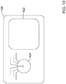
- FIG. 2 depicts an embodiment of another device, medical device (MD) 200, which may operate to sense physiological signals and parameters and/or deliver one or more types of electrical stimulation therapy to tissues of the patient.
- MD 200 may include a communication module 202, a pulse generator module 204, an electrical sensing module 206, a mechanical sensing module 208, a processing module 210, and an energy storage module 218.
- modules 202, 204, 206, 208, and 210 may be similar to modules 102, 104, 106, 108, and 110 of LCP 100.
- energy storage module 218 may be similar to energy storage module 112 of LCP 100.
- MD 200 may have a larger volume within housing 220.
- MD 200 may include a larger energy storage module 218 and/or a larger processing module 210 capable of handling more complex operations than processing module 110 of LCP 100.
- MD 200 may be another leadless device such as shown in FIG. 1
- MD 200 may include leads, such as leads 212.
- Leads 212 may include electrical wires that conduct electrical signals between electrodes 214 and one or more modules located within housing 220. In some cases, leads 212 may be connected to and extend away from housing 220 of MD 200. In some embodiments, leads 212 are implanted on, within, or adjacent to a heart of a patient. Leads 212 may contain one or more electrodes 214 positioned at various locations on leads 212 and various distances from housing 220. Some leads 212 may only include a single electrode 214, while other leads 212 may include multiple electrodes 214.
- electrodes 214 are positioned on leads 212 such that when leads 212 are implanted within the patient, one or more of the electrodes 214 are positioned to perform a desired function. In some cases, the one or more of the electrodes 214 may be in contact with the patient's cardiac tissue. In other cases, the one or more of the electrodes 214 may be positioned subcutaneously but adjacent the patient's heart. The electrodes 214 may conduct intrinsically generated electrical cardiac signals to leads 212. Leads 212 may, in turn, conduct the received electrical cardiac signals to one or more of the modules 202, 204, 206, and 208 of MD 200. In some cases, MD 200 may generate electrical stimulation signals, and leads 212 may conduct the generated electrical stimulation signals to electrodes 214.
- Electrodes 214 may then conduct the electrical stimulation signals to the cardiac tissue of the patient (either directly or indirectly).
- MD 200 may also include one or more electrodes 214 not disposed on a lead 212.
- one or more electrodes 214 may be connected directly to housing 220.
- Leads 212 may additionally contain one or more sensors, such as accelerometers, blood pressure sensors, heart sound sensors, blood-oxygen sensors, and/or other sensors which are configured to measure one or more physiological parameters of the heart and/or patient.
- sensors such as accelerometers, blood pressure sensors, heart sound sensors, blood-oxygen sensors, and/or other sensors which are configured to measure one or more physiological parameters of the heart and/or patient.
- mechanical sensing module 208 may be in electrical communication with leads 212 and may receive signals generated from such sensors.
- MD 200 may be an implantable medical device.
- housing 220 of MD 200 may be implanted in, for example, a transthoracic region of the patient.
- Housing 220 may generally include any of a number of known materials that are safe for implantation in a human body and may, when implanted, hermetically seal the various components of MD 200 from fluids and tissues of the patient's body.
- leads 212 may be implanted at one or more various locations within the patient, such as within the heart of the patient, adjacent to the heart of the patient, adjacent to the spine of the patient, or any other desired location.
- MD 200 may be an implantable cardiac pacemaker (ICP).
- MD 200 may have one or more leads, for example leads 212, which are implanted on or within the patient's heart.
- the one or more leads 212 may include one or more electrodes 214 that are in contact with cardiac tissue and/or blood of the patient's heart.
- MD 200 may be configured to sense intrinsically generated cardiac electrical signals and determine, for example, one or more cardiac arrhythmias based on analysis of the sensed signals.
- MD 200 may be configured to deliver CRT, ATP therapy, bradycardia therapy, and/or other therapy types via leads 212 implanted within the heart.
- MD 200 may additionally be configured to provide defibrillation/cardioversion therapy.
- one of leads 212 may be a subcutaneously implanted lead.
- MD 200 may include only a single lead which is implanted subcutaneously but outside of the chest cavity, however this is not required.
- MD 200 may not be an implantable medical device. Rather, MD 200 may be a device external to the patient's body, and electrodes 214 may be skin-electrodes that are placed on a patient's body. In such embodiments, MD 200 may be able to sense surface electrical signals (e.g. electrical cardiac signals that are generated by the heart or electrical signals generated by a device implanted within a patient's body and conducted through the body to the skin). MD 200 may further be configured to deliver various types of electrical stimulation therapy, including, for example, defibrillation therapy via skin-electrodes 214.
- surface electrical signals e.g. electrical cardiac signals that are generated by the heart or electrical signals generated by a device implanted within a patient's body and conducted through the body to the skin.
- MD 200 may further be configured to deliver various types of electrical stimulation therapy, including, for example, defibrillation therapy via skin-electrodes 214.
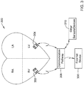
- FIG. 3 illustrates an embodiment of a medical device system and a communication pathway through which multiple medical devices 302, 304, 306, and/or 310 of the medical device system may communicate.
- medical device system 300 may include LCPs 302 and 304, external medical device 306, and other sensors/devices 310.
- External device 306 may be a device disposed external to a patient's body, as described previously with respect to MD 200.
- external device 306 may represent an external support device such as a device programmer, as will be described in more detail below.
- Other sensors/devices 310 may be any of the devices described previously with respect to MD 200, such as ICPs, ICDs, and SICDs.
- Other sensors/devices 310 may also include various diagnostic sensors that gather information about the patient, such as accelerometers, blood pressure sensors, or the like. In some cases, other sensors/devices 310 may include an external programmer device that may be used to program one or more devices of system 300.
- LCPs 302 and/or 304 may sense intrinsic cardiac electrical signals and may communicate such signals to one or more other devices 302/304, 306, and 310 of system 300 via communication pathway 308.
- one or more of devices 302/304 may receive such signals and, based on the received signals, determine an occurrence of an arrhythmia.
- device or devices 302/304 may communicate such determinations to one or more other devices 306 and 310 of system 300.
- one or more of devices 302/304, 306, and 310 of system 300 may take action based on the communicated determination of an arrhythmia, such as by delivering a suitable electrical stimulation to the heart of the patient.
- One or more of devices 302/304, 306, and 310 of system 300 may additionally communicate command or response messages via communication pathway 308.
- the command messages may cause a receiving device to take a particular action whereas response messages may include requested information or a confirmation that a receiving device did, in fact, receive a communicated message or data.
- the various devices of system 300 may communicate via pathway 308 using RF signals, inductive coupling, optical signals, acoustic signals, or any other signals suitable for communication. Additionally, in at least some embodiments, the various devices of system 300 may communicate via pathway 308 using multiple signal types. For instance, other sensors/device 310 may communicate with external device 306 using a first signal type (e.g. RF communication) but communicate with LCPs 302/304 using a second signal type (e.g. conducted communication). Further, in some embodiments, communication between devices may be limited.
- a first signal type e.g. RF communication
- LCPs 302/304 e.g. conducted communication
- LCPs 302/304 may communicate with external device 306 only through other sensors/devices 310, where LCPs 302/304 send signals to other sensors/devices 310, and other sensors/devices 310 relay the received signals to external device 306.
- the various devices of system 300 may communicate via pathway 308 using conducted communication signals. Accordingly, devices of system 300 may have components that allow for such conducted communication. For instance, the devices of system 300 may be configured to transmit conducted communication signals (e.g. current and/or voltage pulses, referred herein as electrical communication pulses) into the patient's body via one or more electrodes of a transmitting device, and may receive the conducted communication signals via one or more electrodes of a receiving device. The patient's body may "conduct" the conducted communication signals from the one or more electrodes of the transmitting device to the electrodes of the receiving device in the system 300.
- conducted communication signals e.g. current and/or voltage pulses, referred herein as electrical communication pulses
- the delivered conducted communication signals may differ from pacing pulses, defibrillation and/or cardioversion pulses, or other electrical stimulation therapy signals.
- the devices of system 300 may deliver electrical communication pulses at an amplitude/pulse width that is sub-threshold. That is, the communication pulses may have an amplitude/pulse width designed to not capture the heart.
- the amplitude/pulse width of the delivered electrical communication pulses may be above the capture threshold of the heart, but may be delivered during a refractory period of the heart and/or may be incorporated in or modulated onto a pacing pulse, if desired.
- the delivered electrical communication pulses may be notches or other disturbances in a pacing pulse.
- the electrical communication pulses may be delivered in specific sequences which convey information to receiving devices.
- delivered electrical communication pulses may be modulated in any suitable manner to encode communicated information.
- the communication pulses may be pulse width modulated and/or amplitude modulated.
- the time between pulses may be modulated to encode desired information.
- a predefined sequence of communication pulses may represent a corresponding symbol (e.g. a logic "1" symbol, a logic "0" symbol, an ATP therapy trigger symbol, etc.).
- conducted communication pulses may be voltage pulses, current pulses, biphasic voltage pulses, biphasic current pulses, or any other suitable electrical pulse as desired.
- FIG. 4 shows an illustrative medical device system 400 that may be configured to operate according to techniques disclosed herein.
- the system may include multiple devices connected to a patient represented by heart 410 and skin 415, where at least some of the devices are configured for communication with other devices.
- an LCP 402 is shown fixed to the interior of the right ventricle of the heart 410
- external support device 420 and external defibrillator 406 are shown connected to skin 415 through skin electrodes 404 and 408, respectively.
- External support device 420 can be used to perform functions such as device identification, device programming and/or transfer of real-time and/or stored data between devices using one or more of the communication techniques described herein.
- LCP 402 and external support device 420 are configured to communicate through conducted communication.
- external defibrillator 406 may be configured to deliver a voltage and/or current signal into the patient through skin 415 as a patch-integrity signal, and may further sense the patch-integrity signal in order to determine information about the contact between electrodes 408 and skin 415. External defibrillator 406 may be configured to display or emit an alarm if the received patch-integrity signal indicates insufficient contact between electrodes 408 and skin 415 to achieve sufficient sensing by the patch electrodes 408 of cardiac electrical signals of heart 410 and/or for safe delivery of defibrillation and/or cardioversion pulses.
- the patch-integrity signal may represent a continuous signal, such as a sine-wave, square-wave, saw-tooth wave, or the like.
- the patch-integrity signal may have a frequency of between about 50 kHz and about 150 kHz, but this is not required. In some instances, this patch-integrity signal may interfere with the conducted communication signals delivered and received by LCP 402 and external support device 420. Accordingly, the LCP 402 and/or external support device 420 may employ one or more techniques for enhancing the effectiveness of their conducted communication scheme, as described in more detail below.
- FIG. 4 is just one example system that may benefit from the techniques disclosed herein.
- Other system may include additional and/or different devices, but may still include a device delivering a conducted signal into the body of a patient that may interfere with conducted communication signals delivered into the patient's body for inter-device communication.
- other systems may have different communication schemes that use additional communication modalities and/or include intermediary devices that receive conducted communication signals from a first device and relay received messages to a second device.
- FIG. 5 depicts an example conducted communication signal 500 that may be received by LCP 402.
- external support device 420 as a transmitter and LCP 402 as a receiver
- the below described techniques may be implemented by any device of a system, such as system 400, with any of the devices of the system acting as the transmitter and any of the devices of the system acting as the receiver. This may include inter-device communication between, for example, two or more implanted medical devices, such as LCP 402 and another LCP (not shown in FIG 4 .) and/or other implanted device.
- conducted communication signal 500 includes signal component 502 and noise component 504.
- signal component 502 represents a series of communication pulses 503 delivered by external support device 420 (or other internal or external device).
- noise component 504 represents a patch-integrity signal delivered by external defibrillator 406.
- LCP 402 may perform initial amplification and/or filtering.
- Conducted communication signal 500 of FIG. 5 may represent the output of the initial amplification and/or filtering.
- LCP 402 may provide the conducted communication signal 500 to a comparator circuit, which may be part of a communication module of LCP 402.
- the comparator circuit may compare the conducted communication signal 500 to a receive threshold, such as a programmable receive threshold 505.
- a receive threshold such as a programmable receive threshold 505.
- the comparator circuit may produce a pulse each time the conducted communication signal 500 is above the programmable receive threshold 505, resulting in a conducted communication signal 550 such as shown in FIG. 6 . That is, in the example shown, the comparator circuit may generate a high signal (e.g. one of pulses 552) whenever the amplitude of conducted communication signal 500 is higher than the receive threshold 505.
- the specific characteristics or spacing of received pulses may convey information.
- LCP 402 and external support device 420 may be configured according to a specific communication protocol, whereby specific patterns of pulse characteristics and/or pulse spacing may represent predefined messages. Some example messages may include identification messages, commands, requests for data, and the like. If a received set of pulses do not have the characteristics that correspond to a recognized message format, the device may determine that a valid message has not been received, and conversely if a received set of pulses do have the characteristics that correspond to a recognized message formats, the device may determine that a valid message has been received.
- LCP 402 and/or external support device 420 may also determine whether a received message is valid by checking a received message for errors.
- the receiving device even after receiving a series of pulses that correspond to a recognized message format, may employ one or more error checking schemes, such as repetition codes, parity bits, checksums, cyclic redundancy checks (CRC), or the like.
- error checking schemes such as repetition codes, parity bits, checksums, cyclic redundancy checks (CRC), or the like.
- CRC cyclic redundancy checks
- conducted communication signal 550 includes pulses 552 generated from both signal component 502 and noise component 504 of conducted communication signal 500. Accordingly, and in some instances, LCP 402 may determine that conducted communication signal 550 is not a valid message as the pulse pattern will not match a recognized message format. In this example, receive threshold 505 is set too low such that portions of noise component 504 have an amplitude high enough to pass through the comparator circuit and generate pulses 552 in conducted communication signal 550.
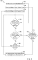
- FIG. 7 is a flow diagram of an illustrative method 700 that LCP 402 (or another device) may implement in order to adjust receive threshold 505 based, at least in part, on the amplitude of conducted communication signal 500. Adjusting receive threshold 505 to be above the amplitude of noise component 504 of conducted communication signal 500 may allow only signal component 502 to pass through the comparator circuit resulting in a conducted communication signal that only includes pulses due to signal component 502. This may produce a valid message received at LCP 402.
- LCP 402 may begin by setting receive threshold 505 to an initial value, as shown at 702.
- the initial value may be set such that, under most conditions, receive threshold 505 is below the amplitude of signal component 502 of conducted communication signal 500.
- LCP 402 may reset and begin a communication window timer, as shown at 704, and reset and begin a communication session timer, as shown at 706.
- LCP 402 may begin the communication window timer only at predefined times. For instance, the communication window timer may be synchronized to line up with one or more features of a sensed cardiac electrical signal, such as an R-wave.
- LCP 402 may wait to start the communication window timer until sensing a particular feature in the cardiac electrical signal. In at least some instances, LCP 402 may start the communication window timer after a predefined time after sensing the particular feature. As one example, LCP 402 may wait between about 50 ms and about 150 ms after sensing an R-wave to begin the communication window timer.
- LCP 402 may count the number of received pulses in a received conducted communication signal, as shown at 708. For instance, received conducted communication signal 500 may be passed through the comparator circuit using receive threshold 505, resulting in conducted communication signal 550. As one example implementation, LCP 402 may increment a pulse count value every time LCP 402 detects a pulse in conducted communication signal 550.
- LCP 402 may determine whether the communication session timer has exceeded the communication session timer threshold, as shown at 710. If the communication session timer has exceeded the communication session timer threshold, LCP 402 may begin method 700 again back at 702. The communication session timer may help ensure that if receive threshold 505 ever gets set above the maximum amplitude of signal component 502 of conducted communication signal 500, receive threshold 505 is reset to a lower value.
- step 702 includes setting receive threshold 505 back to its initial value, in some instances, if LCP 402 arrives at step 702 through block 712, LCP 402 may set receive threshold 505 to a lower value that is different than the initial value. For instance, LCP 402 may simply reduce the value of receive threshold 505 instead of setting it back to its initial value.
- LCP 402 may determine whether the communication window timer has exceeded the communication window timer threshold, as shown at 712. If LCP 402 determines that the communication window timer exceeded the communication window timer threshold, LCP 402 may reset the pulse count and reset and begin the communication window timer, as shown at 720, and then begin again with counting received pulses at 708.
- LCP 402 may determine whether a valid message was received, as shown at 714. For example, LCP 402 may compare the pattern of received pulses to predefined pulse patterns that represent messages. In some instances, LCP 402 may run one or more error checking schemes before or after determining whether the pattern of received pulses corresponds to one of the predefined pulse patterns. LCP 402 may determine that a valid message has been received after determining that the pattern of received pulses corresponds to one of the predefined pulse patterns, and if so provided, after determining that t there are no errors, or significant errors, in the received pulse pattern. If LCP 402 determines that a valid message has been received, LCP 402 may begin the method again at block 706, such as by following the 'YES' branch of block 714.
- LCP 402 may determine whether the pulse count is greater than the pulse count threshold, as shown at 716.
- the pulse count threshold may be set to above a maximum number of pulses that LCP 402 could possibly receive in a valid message. For instance, if each message may correspond to a predefined pulse pattern or sequence, there may be a maximum number of pulses that may be sent in a given message. Accordingly, if LCP 402 receives a number of pulses that is above the pulse count threshold within a communication window, LCP 402 may conclude that the conducted communication signal 550 has been corrupted by noise.
- LCP 402 may increase the value of receive threshold 505 and reset the pulse count, as shown at 718, and begin method 700 again at step 704.
- LCP 402 may increase the value of receive threshold 505 by a predetermined amount, based on how long it took for the number of received pulses to exceed the pulse count threshold, based on how much the number of received pulses exceeded the pulse count threshold, and/or based on any other suitable criteria. If the pulse count has not exceed the pulse count threshold, LCP 402 may loop back to step 708 and continue counting received pulses.
- LCP 402 may wait until the end of a communication window to determine whether a valid message was received and whether the pulse count exceeded the pulse count threshold.
- blocks 714 and 716 may be connected to the 'YES' branch block 712, such that LCP 402 only determines whether a valid message was received and whether the pulse count exceeded the pulse count threshold after the communication window timer exceeds the communication window timer threshold.
- Block 720 may then be connected to the 'NO' branch of block 716.
- the LCP 402 may be configured to adjust receive threshold 505 based at least in part on the amplitude of conducted communication signal 500. Setting receive threshold 505 at an appropriate level effectively filters out noise component 504 in conducted communication signal 550.
- method 700 may work to increase receive threshold 505 above the peak amplitude of noise component 504 such that the peaks of noise component 504 are below receive threshold 505 such that the comparator circuit does not produce corresponding pulses in conducted communication signal 550.
- receive threshold 505 may remain below the peak amplitude of signal component 502, such that the comparator circuit does produce pulses in conducted communication signal 550 that correspond to the pulses in signal component 502.
- FIG. 8 depicts conducted a communication signal 550a, which represents the output of the comparator circuit when the receive threshold 505 had been set higher than the maximum amplitude of noise component 504 but lower than the maximum amplitude of signal component 502.
- conducted communication signal 550 only includes pulses due to signal component 502 of conducted communication signal 500.
- LCP 402 may interpret conducted communication signal 550a as a valid message.
- FIG. 9 depicts a flowchart of another illustrative method 750 that LCP 402 (or another device) may use to adjust the receive threshold 505.
- the receive threshold 505 may be adjusted based, at least in part, on the amplitude of conducted communication signal 500.
- LCP 402 may receive regular messages from another device, such as external support device 420. In one example, at least one message may be received during each communication window.
- LCP 402 may begin, as shown in method 700, by setting receive threshold 505 to an initial value, resetting and beginning a communication window timer, and resetting and beginning a communication session timer, as shown at 752, 754, and 756, respectively.
- LCP 452 may determine whether the communication session timer has exceeded the communication session timer threshold, as shown at 758.
- LCP 402 may determine whether the communication window timer has exceeded the communication window timer threshold, as shown at 760. If LCP 402 determines that the communication window timer has not exceeded the communication window timer threshold, LCP 402 may determine whether a valid message has been received, as shown at 764. If no valid messaged has been received, LCP 402 may loop back to block 758. In this manner, LCP 402 may continue to check whether a valid message has been received during a communication window.
- receive threshold 505 is set too low, e.g. below the maximum amplitude of noise component 504, LCP 402 will not readily receive valid messages and will then increase the receive threshold 505. This will continue until receive threshold 505 is set above the amplitude of noise component 504 and LCP 402 may begin to receive valid messages based on only the signal component 502.
- LCP 402 may wait until after the communication window timer has exceeded the communication window timer threshold before determining whether a valid message has been received.
- method 750 may not include block 764 at all. Instead, the 'NO' branch of block 760 may connect directly to block 756.
- LCP 402 may wait longer than a single communication window period before determining whether a pulse count exceeds a pulse count threshold or whether a valid message was received. For example, LCP 402 may wait until two, three, or even four communication windows have elapsed before making any determinations. These are just some example alternatives to the method shown in FIG. 9 .
- FIG. 10 depicts another method for adjusting the receive threshold 505.
- FIG. 10 depicts conducted communication signal 500 along with a dynamic receive threshold 505a, where the dynamic receive threshold 505a is reset to a new value on each of the peaks of conducted communication signal 500 that exceed the then present dynamic receive threshold 505a.
- dynamic receive threshold 505a may be set to an initial value and may be configured to decay over time to lower values. It should be understood that the decay shape of dynamic receive threshold 505a depicted in FIG. 10 is an example only. In one non-limiting example, dynamic receive threshold 505a may decay to about half of its initial value after 100 ms, and then decay to about one-quarter of its initial value over the subsequent 100 ms. The specific decay values and time periods may differ. It is contemplated that dynamic receive threshold 505a may decay in a logarithmic or natural logarithmic fashion, in an exponential fashion, in a step wise fashion, or any other desirable way.
- dynamic receive threshold 505a is configured to decay after the conducted communication signal 500 reaches a peak amplitude that is above the then existing dynamic receive threshold 505a.
- the dynamic receive threshold 505a begins to decay at peak 800 and at the end of peak 801.
- LCP 402 may reset the dynamic receive threshold 505a to a new higher value when conducted communication signal 500 reaches a new peak amplitude that is above the then existing dynamic receive threshold 505a.
- LCP 402 may continually reset dynamic receive threshold 505a to a new, higher value as conducted communication signal 500 keeps providing peaks that exceed the decaying dynamic receive threshold 505a.
- dynamic receive threshold 505a may be configured to wait to decay for a short predefined time period after being set to a new value.
- LCP 402 may wait to determine a peak of conducted communication signal 500.
- resetting a new, higher value for dynamic receive threshold 505a may lag conducted communication signal 500 by a short period of time.
- LCP 402 may set dynamic receive threshold 505a to a value that is proportional to the most recent peak of conducted communication signal 500. For instance, LCP 402 may set dynamic receive threshold 505a to a value that is between 60%-99% of the maximum value of the most recent peak. This is just one example. Other examples include between 70%-99%, 80%-99%, or 90%-99% of the maximum value of the most recent peak of conducted communication signal 500.
- the decay characteristics of the dynamic receive threshold 505a may be based, at least partially, on the characteristics of the conducted communication signal 500.
- dynamic receive threshold 505a may be configured to decay more quickly for higher values of the dynamic receive threshold 505a.
- dynamic receive threshold 505a may be configured to decay more quickly the longer it has been since the dynamic receive threshold 505a has been reset, which would correspond to a longer period of low amplitude activity of conducted communication signal 500.
- LCP 402 may employ an adaptive filter to help filter out noise component 504.
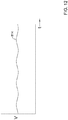
- the patch-integrity signal of an external defibrillator 406 may be a continuous signal having generally static characteristics, such as frequency and/or amplitude.
- LCP 402 may sense, outside of a communication period, the patch-integrity signal.
- LCP 402 may then process the patch-integrity signal to determine at least the frequency of the signal and may configure an adaptive filter into a notch filter centered at the frequency of the patch-integrity signal.
- the notch filter may be particularly effective in filtering out, or at least reducing in amplitude, the noise component 504.
- one or more of the devices of system 400 may be configured to actively cancel the patch-integrity signal.
- one or more of the devices of system 400 may inject a cancelling or inverse signal into the patient body in order to cancel out, or at least reduce the amplitude of, the patch-integrity signal delivered by external defibrillator 406.
- external support device 420 only as an example of a device that may perform the described techniques. It should be understood, however, that the techniques described herein may be applied by any of the devices of system 400, or by other devices in other systems as desired.
- FIG. 11A depicts an example patch-integrity signal 810 signal that may be delivered by an external defibrillator 406.
- External support device 420 may sense signals propagating through a patient's body, including patch-integrity signal 810, during a period of relative electrical quietness within the patient's body. For instance, external support device 420 may sense propagating electrical signals in the patient via electrodes 404 between heartbeats of the patient and while no conducted communication signals are propagating through the patient's body. Where patch-integrity signal 810 is sufficiently different from other signals propagating through the patient's body, external support device 420 may employ one or more filters to filter out signals other than patch-integrity signal 810, leaving only patch-integrity signal 810.
- external support device 420 may employ one or more low-pass, high-pass, bandpass, notch, and/or any other suitable filter.
- External support device 420 may determine various characteristics of patch-integrity signal 810. For instance, external support device 420 may determine the frequency components, the amplitude, and/or the phase of patch-integrity signal 810.
- external support device 420 may include a pulse generator module whereby external support device 420 may generate varied waveforms. After external support device 420 senses patch-integrity signal 810, external support device 420 may generate a cancelling or inverse signal 812 (see FIG. 11B ) using the determined characteristics. For instance, external support device 420 may generate inverse signal 812 to have a similar amplitude and frequency as patch-integrity signal 810. However, external support device 420 may generate inverse signal 812 at a phase that is shifted relative to inverse signal 812 by one-hundred eighty degrees. An example of inverse signal 812 is depicted in FIG.11B . If the patch-integrity signal 810 is not a regular signal as shown in FIG.
- the external support device 420 may simply generate an inverse signal 812 that will cancel out, or at least reduce the amplitude of, the patch-integrity signal 810.
- Other example inverse signals may include signals that are not true inverses of the patch-integrity signal.
- the inverse signal when added to the patch-integrity signal, may reduce the amplitude of the patch-integrity signal received at a device of the system which includes external support device 420.
- the inverse signal when added to the patch-integrity signal, may produce a signal that is received by a device of the system that include external support device 420 having an increased frequency than the original patch-integrity signal. This increased frequency of the patch-integrity signal may allow the signal to be more easily filtered out by the receiving device.
- external support device 420 may generate an inverse signal that is not a true inverse signal, but interferes or changes the patch-integrity signal sufficiently to allow a receiving device to distinguish between the patch-integrity signal and communication signals or to filter the patch-integrity signal without filtering communication signals.
- inverse signal 812 may only be similar to patch-integrity signal 810 and may only reduce the amplitude of patch-integrity signal 810 sensed by LCP 402.
- the delivered inverse signal 812 may reduce the amplitude of patch-integrity signal 810 sensed by LCP 402, which can enhance the signal-to-noise ratio (SNR) of conducted communication between external support device 420 and LCP 402 (and/or between LCP 402 and another implanted devices).
- SNR signal-to-noise ratio
- external support device 420 may generate inverse signal 812 having a different amplitude than patch-integrity signal 810.
- the amplitude of patch-integrity signal 810 sensed by devices connected to the patient other than external support device 420, such as LCP 402 may differ than the amplitude of patch-integrity signal 810 sensed by external support device 420. Accordingly, delivering inverse signal 812 into the patient with an amplitude similar to patch-integrity signal 810 sensed by external support device 420 may cancel out patch-integrity signal 810 sensed by LCP 402, but may additionally introduce noise in the form of inverse signal 812, which was not fully cancelled out by patch-integrity signal 810.
- external support device 420 may generate inverse signal 812 having an amplitude higher, or lower, than the amplitude of patch-integrity signal 810 sensed by external support device 420.
- External support device 420 may attempt to match the amplitude of inverse signal 812 sensed by LCP 402 to the amplitude of patch-integrity signal 810 sensed by LCP 402.
- external support device 420 may adjust the amplitude of inverse signal 812 based on feedback received from LCP 402, or based on a presence or absence of received messages from LCP 402.
- external support device 420 may include a physical dial or gain adjuster 424 that a user may adjust to increase or decrease the amplitude of generated inverse signal 812 (see FIG. 13 ).
- Delivering inverse signal 812 into the patient's body may enhance the signal-to-noise ratio (SNR) of conducted communication with the body by removing or reducing the patch-integrity signal 810 in the body.
- external support device 420 may deliver inverse signal 812 into the patient's body continuously.
- the delivered inverse signal 812 may cause external defibrillator 406 to generate or emit an alarm as patch-integrity signal 810 sensed by external defibrillator 406 may be fully cancelled or reduced in amplitude below a certain alarm threshold. Accordingly, in some cases, external support device 420 may only selectively deliver inverse signal 812 into the patient's body.
- external support device 420 may only deliver inverse signal 812 into the patient's body while external support device 420 or LCP 402 are delivering conducted communication signals into the patient's body.
- LCP 402 may have an easier time discriminating between the delivered conducted communication signals from patch-integrity signal 810.
- the conducted communication scheme of external support device 420 and LCP 402 may include only delivering conducted communication signals during predefined time periods.
- external support device 420 and LCP 402 may be configured to only deliver conducted communication signals during communication windows lasting about 100 ms, with each communication window separated by 800 ms. These numbers are just examples.
- the communication window lengths and spacing may be any suitable values.
- the communication windows may be synchronized to one or more features of the cardiac electrical signals.
- external support device 420 and LCP 402 may be configured to communication during communication windows that occur about 100-250 ms after each detected R-wave.
- External support device 420 may be configured to only deliver inverse signal 812 into the patient's body during these communication windows. Both external support device 420 and LCP 402 may benefit from enhanced discrimination between sensed conducted communication signals and patch-integrity signal 810.
- FIG. 13 depicts an example interface of an external support device 420.
- External support device 420 may include a dial, switch, or other mechanical selector, such as dial 424, or a menu option in graphical user interface 422, that allows a user to select a particular inverse waveform from a set of preprogrammed inverse waveforms that correspond to the different available external defibrillators.
- the preprogrammed inverse waveforms may be stored in a memory of external support device 420.
- Each selectable waveform may have an identifier correlating the waveform to a particular brand or product to easily identify the appropriate inverse waveform.
- FIG. 14 depicts system 900 which may help enhance discrimination between conducted communication signals and noise signals such as patch-integrity signals.
- System 900 may include external support device 920, external defibrillator 906, and switching unit 910.
- External defibrillator 906 may be connected to switching unit 910 through wires 908, and external support device 920 may be connected to switching unit 910 by wires 922.
- Switching unit 910 may be connected to electrodes 904 attached to patient skin 915 through wires 912.
- a switching unit 910 may be configured to switch between wires 922 from external support device 920 and wires 908 from external defibrillator 906 to connect/disconnect each device to electrodes 904.
- Switching unit 910 may initially connect wires 908 to electrodes 904, allowing external defibrillator 906 to deliver a patch-integrity signal through electrode 904 and into the patient through skin 915.
- switching unit 910 may disconnect wires 908 of external defibrillator 906 from the electrodes 904 and connect wires 922 from external support device 920 to the electrodes 904. In this configuration, external support device 920 may deliver conducted communication signals into the patient through electrodes 904.
- the patch-integrity signal is effectively blocked from entering the patient, and devices may communicate through conducted communication signals without interference from the patch-integrity signal.
- switching unit 910 may disconnect wires 922 of the external support device 920 from the electrodes 904 and connect wires 908 of the external defibrillator 906 to the electrodes 904.
- the patch-integrity signal of the external defibrillator 906 may then be delivered to the patient, verifying to the external defibrillator 906 that the patch electrodes 904 are sufficiently in electrical communication with the skin. If the communication period is kept short enough, a patch verification alarm of the external defibrillator 906 may not be triggered.
- external support device 920 may control switching unit 910 to connect/disconnect wires 908, 922 from wires 912.
- external defibrillator 906 may control switching unit 910, a different device may control switching unit 910, or both of external defibrillator 906 and external support device 920 may control switching unit 910.
- the techniques are described below from the perspective of external support device 920 controlling switching unit 910.
- external defibrillator 906 may normally be connected to electrode 904 to deliver a patch-integrity signal and/or sense cardiac electrical signals.
- external support device 920 may command switching unit 910 to disconnect wires 908 of the external defibrillator 906 from the electrodes 904 and connect wires 922 of the external support device 920 to the electrodes 904, thereby blocking the patch-integrity signal from external defibrillator 906 from being delivered to the patient.
- external support device 920 may command switching unit 910 to reconnect wires 908 of the external defibrillator 906 to the electrodes 904.
- external support device 920 may cause switching unit 910 to switch at regular intervals. For instance, in some cases where external support device 920 and another device, such as an LCP device, are connected to the patient and are configured to communicate using conducted communication only during predefined communication windows, external support device 920 may command switching unit 910 to connect wires 922 of the external support device 920 to the electrodes 904 during each of the communication windows.
- wires 908 of the external defibrillator 906 When wires 908 of the external defibrillator 906 are disconnected from the electrodes 904, wires 908 may form an open circuit which may cause external defibrillator 906 to generate or emit an alarm, as external defibrillator 906 may no longer sense the patch-integrity signal.
- switching unit 910 when switching unit 910 disconnects wires 908 of the external defibrillator 906 from the electrodes 904, switching unit 910 may connect wires 908 directly together, or may connect wires 908 together through a resistive or other network contained within switching unit 910. In these embodiments, switching unit 910 may maintain a closed loop for the patch-integrity signal, which may help prevent external defibrillator 906 from generating or emitting an alarm.
- system 900 is depicted as including external defibrillator 906, switching unit 910, and external support device 920, it is contemplated that system 900 may include fewer or more devices.
- the support functions of external support device 920 and the switching functions of switching unit 910 may be built into external defibrillator 906.
- external defibrillator 906 may have an internal switching mechanism and can control the switching mechanism to help support conducted communication via other devices within the patient.
Description
- The present disclosure generally relates to systems, devices, and methods for communicating between medical devices, and more particularly, to systems, devices, and methods for communicating between medical devices using conducted communication.
- Active implantable medical devices are routinely implanted with a patient's body. Such implantable medical devices are often used to provide therapy, diagnostics or both. In some cases, it can be desirable to communicate with such implantable medical devices via the skin, such as via a programmer or the like located outside of the body. Such communication can be though conducted communication, which conducts electrical current through the patient's body tissue from one device to the other. In the programmer example, the programmer may be electrically connected to the patient's body through electrode skin patches or the like. Such communication may facilitate the programmer in programing and/or re-programing the implantable medical device, reading data collected by the implantable medical device, and/or collecting or exchanging any other suitable information. In some instances, two or more implantable medical devices may be implanted with a patient. In such cases, it can be desirable to establish communication between the two or more implanted medical devices using conducted communication. Such communication may facility the implanted medical devices in sharing data, distribution of control and/or delivery of therapy, and/or in performing other desired functions. These are just some example uses of conducted communication in the body.
- Document
US 2011/0160557 A1 provides a system and a method for testing communication through a patient during implantation using telemetry coupling electrodes on a delivery catheter. In one example, at least two telemetry coupling electrodes may be placed on or within a delivery catheter to test conductive communication with external body electrodes during implantation. In some instances, the telemetry coupling electrodes of the delivery catheter may approximate the spacing of telemetry electrodes on an IMD. In this manner, testing conductively coupled communication with telemetry coupling electrodes of the catheter may be used to mimic the telemetry electrodes on the IMD and determine a target position and/or orientation of an electrode or electrodes of the IMD for successful conductive communication through the body. - Document
US 2012/0078322 A1 provides an active implantable medical device having wireless communication of data via electrical pulses conducted by the interstitial tissues of the body. This device includes a pair of electrodes and generates pulse trains consisting of a series of electrical pulses applied to the electrodes. The pulse train is modulated by digital information (data) that is produced by the device. A regulated current or voltage source is used to generate current or voltage pulses to form the pulse train. Each current or voltage pulse is a biphasic pulse comprising a positive and negative alternation. The biphasic current or voltage modulated by the digital information, is injected between the electrodes and wirelessly communicated. - Document
US 2015/0196769 A1 is related to medical devices. At least one of a first medical device and a second medical device may be implanted within a patient while the second medical device may optionally be proximate but external to the patient. At least one of the medical devices has an antenna having at least two electrodes and at least one of the medical devices has an antenna having at least three electrodes. The medical devices can communicate via conducted communication through the patient's tissue between a first pair of electrodes and a second pair of electrodes. At least one of the pairs of electrodes can be selected in accordance with the signal strength of the communication vector between the first and second pairs of electrodes. - Document
US 2012/0109236 A1 describes a leadless pacemaker for pacing a heart of a human including a hermetic housing and at least two electrodes on or near the hermetic housing. The at least two electrodes are configured to deliver energy to stimulate the heart and to transfer information to or from at least one external device. - The present invention is defined by the appended claims.
- Aspects, embodiments, examples and methods of the present disclosure which do not fall within the scope of the appended claims do not form part of the present invention.
- The present disclosure generally relates to systems, devices, and methods for communicating between medical devices, and more particularly, to systems, devices, and methods for communicating between medical devices using conducted communication.
- In one embodiment, a method for communicating with implantable medical devices may comprise sensing, by a first medical device, a noise signal delivered into a patient's body by a second medical device and delivering, by the first medical device, a cancelling signal into the patient's body. In some additional embodiments, the method may further comprise, while delivering the cancelling signal into the patient's body, delivering a conducted communication signal into the patient's body for reception by a second medical device.
- Additionally, or alternatively, in any of the above embodiments, the cancelling signal may be an inverse signal of the noise signal.
- Additionally, or alternatively, in any of the above embodiments, the cancelling signal may at least partially reduce the amplitude of the noise signal received by the second medical device.
- Additionally, or alternatively, any of the above embodiments may further comprise receiving, by the first medical device, a selection of a predetermined cancelling signal and delivering the selected predetermined cancelling signal into the patient's body.
- Additionally, or alternatively, any of the above embodiments may further comprise receiving, by the first medical device, an amplitude selection for the cancelling signal and delivering the cancelling signal into the body of the patient with the selected amplitude.
- Additionally, or alternatively, any of the above embodiments, may further comprise delivering, by the first medical device, the cancelling signal into the patient's body only while delivering the conducted communication signal into the patient's body.
- Additionally, or alternatively, in any of the above embodiments, the noise signal may be a signal delivered into the patient's body by a third medical device.
- Additionally, or alternatively, any of the above embodiments, may further comprise delivering the cancelling signal into the patient's body only during predefined communication windows.
- In another embodiment, a medical device may comprise one or more electrodes and a controller connected to the one or more electrodes. In some embodiments, the controller may be configured to cause the medical device to generate an inverse signal and deliver the inverse signal into a patient's body via the one or more electrodes.
- Additionally, or alternatively, in any of the above embodiments, the controller may be further configured to cause the medical device to generate a conducted communication signal and deliver the conducted communication signal into the patient's body.
- Additionally, or alternatively, in any of the above embodiments, the controller may be further configured cause the medical device to deliver the conducted communication signal and the inverse signal into the patient's body simultaneously.
- Additionally, or alternatively, in any of the above embodiments, the controller may be further configured to cause the medical device to deliver the inverse signal into the patient's body only while delivering the conducted communication signal into the patient's body.
- Additionally, or alternatively, in any of the above embodiments, the controller may be further configured to cause the medical device to sense a signal from the patient's body via the one or more electrodes, and generate the inverse signal as an inverse signal to the sensed signal.
- Additionally, or alternatively, in any of the above embodiments, the controller may be further configured to receive a selection of an inverse signal and wherein the controller may be further configured to cause the medical device to generate the inverse signal based on the received selection.
- Additionally, or alternatively, in any of the above embodiments, the selection may comprise a selection of an inverse signal that is stored within a memory of the medical device.
- Additionally, or alternatively, in any of the above embodiments, the controller may be further configured to cause the medical device to deliver the inverse signal into the patient's body only during predefined communication windows.
- In yet another embodiment, a method of communicating with an implantable medical device may comprise switching, by a first medical device connected to a second medical device, a switch unit to block a signal from being delivered into a patient's body via one or more electrodes of the second medical device and delivering, by the first medical device and via the one or more electrodes of the second medical device, a conducted communication signal into the patient's body.
- Additionally, or alternatively, any of the above embodiments may further comprise switching, by the first medical device, the switch unit to block the signal from being delivered into the patient's body via the one or more electrodes only while delivering the conducted communication signal to the patient's body.
- Additionally, or alternatively, any of the above embodiments may further comprise switching, by the first medical device, the switch unit to direct the blocked signal back to the second medical device without passing through the patient's body.
- Additionally, or alternatively, any of the above embodiments may further comprise directing the blocked signal back to the second medical device through a resistive network other than the patient's body.
- The above summary is not intended to describe each embodiment or every implementation of the present disclosure. Advantages and attainments, together with a more complete understanding of the disclosure, will become apparent and appreciated by referring to the following description and claims taken in conjunction with the accompanying drawings.
- The disclosure may be more completely understood in consideration of the following description of various illustrative embodiments in connection with the accompanying drawings, in which:
-
FIG. 1 is a schematic block diagram of an illustrative leadless cardiac pacemaker (LCP) according to one embodiment of the present disclosure; -
FIG. 2 is a schematic block diagram of another illustrative medical device that may be used in conjunction with the LCP ofFIG. 1 ; -
FIG. 3 is a schematic diagram of an exemplary medical system that includes multiple LCPs and/or other devices in communication with one another; -
FIG. 4 is a schematic diagram of a medical device system including devices that are configured for conducted communication through the body; -
FIG. 5 depicts an example conducted communication signal sensed by a medical device including a noise component and a signal component; -
FIG. 6 depicts an example conducted communication signal after having been relayed through a comparator circuit having a first receive threshold in accordance with techniques of the present disclosure; -
FIG. 7 is a flow diagram of an illustrative method that may be implemented by a medical device or medical device system, such as the illustrative medical devices and medical device systems described with respect toFIGS. 1-4 ; -
FIG. 8 depicts another example conducted communication signal after having been relayed through a comparator circuit with a second receive threshold, in accordance with techniques of the present disclosure; -
FIG. 9 is a flow diagram of an illustrative method that may be implemented by a medical device or medical device system, such as the illustrative medical devices and medical device systems described with respect toFIGS. 1-4 ; -
FIG. 10 depicts another example conducted communication signal along with a decaying receive threshold, in accordance with techniques of the present disclosure; -
FIG. 11A depicts an example patch-integrity signal; -
FIG. 11B depicts an example cancelling or inverse signal which may be generated by a medical device such as the illustrative medical devices and medical device systems described with respect toFIGS. 1-4 , in accordance with the techniques disclosed herein; -
FIG. 12 depicts an example patch-integrity signal that may be sensed by a first medical device while a second medical device is delivering a cancelling or inverse signal, in accordance with techniques disclosed herein; -
FIG. 13 is a schematic diagram of an example user interface that may be included on an external support device; and -
FIG. 14 is a schematic diagram of a medical device system for alternately connecting a first medical device and a second medical device to a pair of electrodes connected to a patient to enhance conducted communication through the patient, in accordance with techniques disclosed herein. - While the disclosure is amenable to various modifications and alternative forms, specifics thereof have been shown by way of example in the drawings and will be described in detail.
- The following description should be read with reference to the drawings in which similar elements in different drawings are numbered the same. The description and the drawings, which are not necessarily to scale, depict illustrative embodiments and are not intended to limit the scope of the disclosure.
- This disclosure describes systems, devices, and methods for communicating between medical devices. Some medical device systems of the present disclosure may communicate using conducted communication techniques, which may include delivering electrical communication signals into a body of a patient for conduction through the patient's body. This signal may be received by another medical device, thereby establishing a communication link between the devices.
-
FIG. 1 is a conceptual schematic block diagram of an exemplary leadless cardiac pacemaker (LCP) that may be implanted on the heart or within a chamber of the heart and may operate to sense physiological signals and parameters and deliver one or more types of electrical stimulation therapy to the heart of the patient. Example electrical stimulation therapy may include bradycardia pacing, rate responsive pacing therapy, cardiac resynchronization therapy (CRT), anti-tachycardia pacing (ATP) therapy and/or the like. As can be seen inFIG. 1 ,LCP 100 may be a compact device with all components housed withinLCP 100 or directly onhousing 120. In some instances,LCP 100 may includecommunication module 102,pulse generator module 104,electrical sensing module 106,mechanical sensing module 108,processing module 110,energy storage module 112, andelectrodes 114. While a leadless cardiac pacemaker (LCP) is used as an example implantable medical device, it is contemplated that any suitable implantable medical device may be used, including implantable medical devices that provide therapy (e.g. pacing, neuro-stimulation, etc.), diagnostics (sensing), or both. - As depicted in
FIG. 1 ,LCP 100 may includeelectrodes 114, which can be secured relative tohousing 120 and electrically exposed to tissue and/orblood surrounding LCP 100.Electrodes 114 may generally conduct electrical signals to and fromLCP 100 and the surrounding tissue and/or blood. Such electrical signals can include communication signals, electrical stimulation pulses, and intrinsic cardiac electrical signals, to name a few. Intrinsic cardiac electrical signals may include electrical signals generated by the heart and may be represented by an electrocardiogram (ECG). -
Electrodes 114 may include one or more biocompatible conductive materials such as various metals or alloys that are known to be safe for implantation within a human body. In some instances,electrodes 114 may be generally disposed on either end ofLCP 100 and may be in electrical communication with one or more ofmodules electrodes 114 are secured directly tohousing 120, an insulative material may electrically isolate theelectrodes 114 from adjacent electrodes,housing 120, and/or other parts ofLCP 100. In some instances, some or all ofelectrodes 114 may be spaced fromhousing 120 and connected tohousing 120 and/or other components ofLCP 100 through connecting wires. In such instances, theelectrodes 114 may be placed on a tail (not shown) that extends out away from thehousing 120. As shown inFIG. 1 , in some embodiments,LCP 100 may include electrodes 114'. Electrodes 114' may be in addition toelectrodes 114, or may replace one or more ofelectrodes 114. Electrodes 114' may be similar toelectrodes 114 except that electrodes 114' are disposed on the sides ofLCP 100. In some cases, electrodes 114' may increase the number of electrodes by whichLCP 100 may deliver communication signals and/or electrical stimulation pulses, and/or may sense intrinsic cardiac electrical signals, communication signals, and/or electrical stimulation pulses. -
Electrodes 114 and/or 114' may assume any of a variety of sizes and/or shapes, and may be spaced at any of a variety of spacings. For example,electrodes 114 may have an outer diameter of two to twenty millimeters (mm). In other embodiments,electrodes 114 and/or 114' may have a diameter of two, three, five, seven millimeters (mm), or any other suitable diameter, dimension and/or shape. Example lengths forelectrodes 114 and/or 114' may include, for example, one, three, five, ten millimeters (mm), or any other suitable length. As used herein, the length is a dimension ofelectrodes 114 and/or 114' that extends away from the outer surface of thehousing 120. In some instances, at least some ofelectrodes 114 and/or 114' may be spaced from one another by a distance of twenty, thirty, forty, fifty millimeters (mm), or any other suitable spacing. Theelectrodes 114 and/or 114' of a single device may have different sizes with respect to each other, and the spacing and/or lengths of the electrodes on the device may or may not be uniform. - In the embodiment shown,
communication module 102 may be electrically coupled toelectrodes 114 and/or 114' and may be configured to deliver communication pulses to tissues of the patient for communicating with other devices such as sensors, programmers, other medical devices, and/or the like. Communication signals, as used herein, may be any modulated signal that conveys information to another device, either by itself or in conjunction with one or more other modulated signals. In some embodiments, communication signals may be limited to sub-threshold signals that do not result in capture of the heart yet still convey information. The communication signals may be delivered to another device that is located either external or internal to the patient's body. In some instances, the communication may take the form of distinct communication pulses separated by various amounts of time. In some of these cases, the timing between successive pulses may convey information.Communication module 102 may additionally be configured to sense for communication signals delivered by other devices, which may be located external or internal to the patient's body. -
Communication module 102 may communicate to help accomplish one or more desired functions. Some example functions include delivering sensed data, using communicated data for determining occurrences of events such as arrhythmias, coordinating delivery of electrical stimulation therapy, and/or other functions. In some cases,LCP 100 may use communication signals to communicate raw information, processed information, messages and/or commands, and/or other data. Raw information may include information such as sensed electrical signals (e.g. a sensed ECG), signals gathered from coupled sensors, and the like. In some embodiments, the processed information may include signals that have been filtered using one or more signal processing techniques. Processed information may also include parameters and/or events that are determined by theLCP 100 and/or another device, such as a determined heart rate, timing of determined heartbeats, timing of other determined events, determinations of threshold crossings, expirations of monitored time periods, activity level parameters, blood-oxygen parameters, blood pressure parameters, heart sound parameters, and the like. Messages and/or commands may include instructions or the like directing another device to take action, notifications of imminent actions of the sending device, requests for reading from the receiving device, requests for writing data to the receiving device, information messages, and/or other messages commands. - In at least some embodiments, communication module 102 (or LCP 100) may further include switching circuitry to selectively connect one or more of
electrodes 114 and/or 114' tocommunication module 102 in order to select whichelectrodes 114 and/or 114' thatcommunication module 102 delivers communication pulses. It is contemplated thatcommunication module 102 may be communicating with other devices via conducted signals, radio frequency (RF) signals, optical signals, acoustic signals, inductive coupling, and/or any other suitable communication methodology. Wherecommunication module 102 generates electrical communication signals,communication module 102 may include one or more capacitor elements and/or other charge storage devices to aid in generating and delivering communication signals. In the embodiment shown,communication module 102 may use energy stored inenergy storage module 112 to generate the communication signals. In at least some examples,communication module 102 may include a switching circuit that is connected toenergy storage module 112 and, with the switching circuitry, may connectenergy storage module 112 to one or more ofelectrodes 114/114' to generate the communication signals. - As shown in
FIG. 1 , apulse generator module 104 may be electrically connected to one or more ofelectrodes 114 and/or 114'.Pulse generator module 104 may be configured to generate electrical stimulation pulses and deliver the electrical stimulation pulses to tissues of a patient via one or more of theelectrodes 114 and/or 114' in order to effectuate one or more electrical stimulation therapies. Electrical stimulation pulses as used herein are meant to encompass any electrical signals that may be delivered to tissue of a patient for purposes of treatment of any type of disease or abnormality. For example, when used to treat heart disease, thepulse generator module 104 may generate electrical stimulation pacing pulses for capturing the heart of the patient, i.e. causing the heart to contract in response to the delivered electrical stimulation pulse. In some of these cases,LCP 100 may vary the rate at whichpulse generator 104 generates the electrical stimulation pulses, for example in rate adaptive pacing. In other embodiments, the electrical stimulation pulses may include defibrillation/cardioversion pulses for shocking the heart out of fibrillation or into a normal heart rhythm. In yet other embodiments, the electrical stimulation pulses may include anti-tachycardia pacing (ATP) pulses. It should be understood that these are just some examples. When used to treat other ailments, thepulse generator module 104 may generate electrical stimulation pulses suitable for neuro-stimulation therapy or the like.Pulse generator module 104 may include one or more capacitor elements and/or other charge storage devices to aid in generating and delivering appropriate electrical stimulation pulses. In at least some embodiments,pulse generator module 104 may use energy stored inenergy storage module 112 to generate the electrical stimulation pulses. In some particular embodiments,pulse generator module 104 may include a switching circuit that is connected toenergy storage module 112 and may connectenergy storage module 112 to one or more ofelectrodes 114/114' to generate electrical stimulation pulses. -
LCP 100 may further include anelectrical sensing module 106 andmechanical sensing module 108.Electrical sensing module 106 may be configured to sense intrinsic cardiac electrical signals conducted fromelectrodes 114 and/or 114' toelectrical sensing module 106. For example, electrical sensing module 1 06 may be electrically connected to one ormore electrodes 114 and/or 114' andelectrical sensing module 106 may be configured to receive cardiac electrical signals conducted throughelectrodes 114 and/or 114' via a sensor amplifier or the like. In some embodiments, the cardiac electrical signals may represent local information from the chamber in whichLCP 100 is implanted. For instance, ifLCP 100 is implanted within a ventricle of the heart, cardiac electrical signals sensed byLCP 100 throughelectrodes 114 and/or 114' may represent ventricular cardiac electrical signals.Mechanical sensing module 108 may include, or be electrically connected to, various sensors, such as accelerometers, blood pressure sensors, heart sound sensors, piezoelectric sensors, blood-oxygen sensors, and/or other sensors which measure one or more physiological parameters of the heart and/or patient.Mechanical sensing module 108, when present, may gather signals from the sensors indicative of the various physiological parameters. Bothelectrical sensing module 106 andmechanical sensing module 108 may be connected toprocessing module 110 and may provide signals representative of the sensed cardiac electrical signals and/or physiological signals toprocessing module 110. Although described with respect toFIG. 1 as separate sensing modules, in some embodiments,electrical sensing module 106 andmechanical sensing module 108 may be combined into a single module. In at least some examples,LCP 100 may only include one ofelectrical sensing module 106 andmechanical sensing module 108. In some cases, any combination of theprocessing module 110,electrical sensing module 106,mechanical sensing module 108,communication module 102,pulse generator module 104 and/or energy storage module may be considered a controller of theLCP 100. -
Processing module 110 may be configured to direct the operation ofLCP 100. For example,processing module 110 may be configured to receive cardiac electrical signals fromelectrical sensing module 106 and/or physiological signals frommechanical sensing module 108. Based on the received signals,processing module 110 may determine, for example, occurrences and types of arrhythmias.Processing module 110 may further receive information fromcommunication module 102. In some embodiments,processing module 110 may additionally use such received information to determine occurrences and types of arrhythmias. In still some additional embodiments,LCP 100 may use the received information instead of the signals received fromelectrical sensing module 106 and/or mechanical sensing module 108 - for instance if the received information is deemed to be more accurate than the signals received fromelectrical sensing module 106 and/ormechanical sensing module 108 or ifelectrical sensing module 106 and/ormechanical sensing module 108 have been disabled or omitted fromLCP 100. - After determining an occurrence of an arrhythmia,
processing module 110 may controlpulse generator module 104 to generate electrical stimulation pulses in accordance with one or more electrical stimulation therapies to treat the determined arrhythmia. For example,processing module 110 may controlpulse generator module 104 to generate pacing pulses with varying parameters and in different sequences to effectuate one or more electrical stimulation therapies. As one example, in controllingpulse generator module 104 to deliver bradycardia pacing therapy,processing module 110 may controlpulse generator module 104 to deliver pacing pulses designed to capture the heart of the patient at a regular interval to help prevent the heart of a patient from falling below a predetermined threshold. In some cases, the rate of pacing may be increased with an increased activity level of the patient (e.g. rate adaptive pacing). For instance,processing module 110 may monitor one or more physiological parameters of the patient which may indicate a need for an increased heart rate (e.g. due to increased metabolic demand).Processing module 110 may then increase the rate at whichpulse generator 104 generates electrical stimulation pulses. - For ATP therapy,
processing module 110 may controlpulse generator module 104 to deliver pacing pulses at a rate faster than an intrinsic heart rate of a patient in attempt to force the heart to beat in response to the delivered pacing pulses rather than in response to intrinsic cardiac electrical signals. Once the heart is following the pacing pulses,processing module 110 may controlpulse generator module 104 to reduce the rate of delivered pacing pulses down to a safer level. In CRT,processing module 110 may controlpulse generator module 104 to deliver pacing pulses in coordination with another device to cause the heart to contract more efficiently. In cases wherepulse generator module 104 is capable of generating defibrillation and/or cardioversion pulses for defibrillation/cardioversion therapy,processing module 110 may controlpulse generator module 104 to generate such defibrillation and/or cardioversion pulses. In some cases,processing module 110 may controlpulse generator module 104 to generate electrical stimulation pulses to provide electrical stimulation therapies different than those examples described above. - Aside from controlling
pulse generator module 104 to generate different types of electrical stimulation pulses and in different sequences, in some embodiments,processing module 110 may also controlpulse generator module 104 to generate the various electrical stimulation pulses with varying pulse parameters. For example, each electrical stimulation pulse may have a pulse width and a pulse amplitude.Processing module 110 may controlpulse generator module 104 to generate the various electrical stimulation pulses with specific pulse widths and pulse amplitudes. For example,processing module 110 may causepulse generator module 104 to adjust the pulse width and/or the pulse amplitude of electrical stimulation pulses if the electrical stimulation pulses are not effectively capturing the heart. Such control of the specific parameters of the various electrical stimulation pulses may helpLCP 100 provide more effective delivery of electrical stimulation therapy. - In some embodiments,
processing module 110 may further controlcommunication module 102 to send information to other devices. For example,processing module 110 may controlcommunication module 102 to generate one or more communication signals for communicating with other devices of a system of devices. For instance,processing module 110 may controlcommunication module 102 to generate communication signals in particular pulse sequences, where the specific sequences convey different information.Communication module 102 may also receive communication signals for potential action by processingmodule 110. - In further embodiments,
processing module 110 may control switching circuitry by whichcommunication module 102 andpulse generator module 104 deliver communication signals and/or electrical stimulation pulses to tissue of the patient. As described above, bothcommunication module 102 andpulse generator module 104 may include circuitry for connecting one ormore electrodes 114 and/114' tocommunication module 102 and/orpulse generator module 104 so those modules may deliver the communication signals and electrical stimulation pulses to tissue of the patient. The specific combination of one or more electrodes by whichcommunication module 102 and/orpulse generator module 104 deliver communication signals and electrical stimulation pulses may influence the reception of communication signals and/or the effectiveness of electrical stimulation pulses. Although it was described that each ofcommunication module 102 andpulse generator module 104 may include switching circuitry, in some embodiments,LCP 100 may have a single switching module connected to thecommunication module 102, thepulse generator module 104, andelectrodes 114 and/or 114'. In such embodiments,processing module 110 may control the switching module to connectmodules 102/104 andelectrodes 114/114' as appropriate. - In some embodiments,
processing module 110 may include a pre-programmed chip, such as a very-large-scale integration (VLSI) chip or an application specific integrated circuit (ASIC). In such embodiments, the chip may be pre-programmed with control logic in order to control the operation ofLCP 100. By using a pre-programmed chip,processing module 110 may use less power than other programmable circuits while able to maintain basic functionality, thereby potentially increasing the battery life ofLCP 100. In other instances,processing module 110 may include a programmable microprocessor or the like. Such a programmable microprocessor may allow a user to adjust the control logic of LCP 1 00 after manufacture, thereby allowing for greater flexibility ofLCP 100 than when using a pre-programmed chip. -
Processing module 110, in additional embodiments, may include a memory circuit andprocessing module 110 may store information on and read information from the memory circuit. In other embodiments,LCP 100 may include a separate memory circuit (not shown) that is in communication withprocessing module 110, such thatprocessing module 110 may read and write information to and from the separate memory circuit. The memory circuit, whether part ofprocessing module 110 or separate fromprocessing module 110, may be volatile memory, non-volatile memory, or a combination of volatile memory and non-volatile memory. -
Energy storage module 112 may provide a power source toLCP 100 for its operations. In some embodiments,energy storage module 112 may be a non-rechargeable lithium-based battery. In other embodiments, the non-rechargeable battery may be made from other suitable materials. In some embodiments,energy storage module 112 may include a rechargeable battery. In still other embodiments,energy storage module 112 may include other types of energy storage devices such as capacitors or super capacitors. - To implant
LCP 100 inside a patient's body, an operator (e.g., a physician, clinician, etc.), may fixLCP 100 to the cardiac tissue of the patient's heart. To facilitate fixation,LCP 100 may include one or more anchors 116. The one ormore anchors 116 are shown schematically inFIG. 1 . The one ormore anchors 116 may include any number of fixation or anchoring mechanisms. For example, one ormore anchors 116 may include one or more pins, staples, threads, screws, helix, tines, and/or the like. In some embodiments, although not shown, one ormore anchors 116 may include threads on its external surface that may run along at least a partial length of an anchor member. The threads may provide friction between the cardiac tissue and the anchor to help fix the anchor member within the cardiac tissue. In some cases, the one ormore anchors 116 may include an anchor member that has a cork-screw shape that can be screwed into the cardiac tissue. In other embodiments,anchor 116 may include other structures such as barbs, spikes, or the like to facilitate engagement with the surrounding cardiac tissue. - In some examples,
LCP 100 may be configured to be implanted on a patient's heart or within a chamber of the patient's heart. For instance,LCP 100 may be implanted within any of a left atrium, right atrium, left ventricle, or right ventricle of a patient's heart. By being implanted within a specific chamber,LCP 100 may be able to sense cardiac electrical signals originating or emanating from the specific chamber that other devices may not be able to sense with such resolution. WhereLCP 100 is configured to be implanted on a patient's heart,LCP 100 may be configured to be implanted on or adjacent to one of the chambers of the heart, or on or adjacent to a path along which intrinsically generated cardiac electrical signals generally follow. In these examples,LCP 100 may also have an enhanced ability to sense localized intrinsic cardiac electrical signals and deliver localized electrical stimulation therapy. -
FIG. 2 depicts an embodiment of another device, medical device (MD) 200, which may operate to sense physiological signals and parameters and/or deliver one or more types of electrical stimulation therapy to tissues of the patient. In the embodiment shown,MD 200 may include acommunication module 202, apulse generator module 204, anelectrical sensing module 206, amechanical sensing module 208, aprocessing module 210, and anenergy storage module 218. Each ofmodules modules LCP 100. Additionally,energy storage module 218 may be similar toenergy storage module 112 ofLCP 100. However, in some embodiments,MD 200 may have a larger volume withinhousing 220. In such embodiments,MD 200 may include a largerenergy storage module 218 and/or alarger processing module 210 capable of handling more complex operations than processingmodule 110 ofLCP 100. - While
MD 200 may be another leadless device such as shown inFIG. 1 , in someinstances MD 200 may include leads, such as leads 212.Leads 212 may include electrical wires that conduct electrical signals betweenelectrodes 214 and one or more modules located withinhousing 220. In some cases, leads 212 may be connected to and extend away fromhousing 220 ofMD 200. In some embodiments, leads 212 are implanted on, within, or adjacent to a heart of a patient.Leads 212 may contain one ormore electrodes 214 positioned at various locations onleads 212 and various distances fromhousing 220. Some leads 212 may only include asingle electrode 214, while other leads 212 may includemultiple electrodes 214. Generally,electrodes 214 are positioned onleads 212 such that when leads 212 are implanted within the patient, one or more of theelectrodes 214 are positioned to perform a desired function. In some cases, the one or more of theelectrodes 214 may be in contact with the patient's cardiac tissue. In other cases, the one or more of theelectrodes 214 may be positioned subcutaneously but adjacent the patient's heart. Theelectrodes 214 may conduct intrinsically generated electrical cardiac signals to leads 212.Leads 212 may, in turn, conduct the received electrical cardiac signals to one or more of themodules MD 200. In some cases,MD 200 may generate electrical stimulation signals, and leads 212 may conduct the generated electrical stimulation signals toelectrodes 214.Electrodes 214 may then conduct the electrical stimulation signals to the cardiac tissue of the patient (either directly or indirectly).MD 200 may also include one ormore electrodes 214 not disposed on alead 212. For example, one ormore electrodes 214 may be connected directly tohousing 220. -
Leads 212, in some embodiments, may additionally contain one or more sensors, such as accelerometers, blood pressure sensors, heart sound sensors, blood-oxygen sensors, and/or other sensors which are configured to measure one or more physiological parameters of the heart and/or patient. In such embodiments,mechanical sensing module 208 may be in electrical communication withleads 212 and may receive signals generated from such sensors. - While not required, in some
embodiments MD 200 may be an implantable medical device. In such embodiments,housing 220 ofMD 200 may be implanted in, for example, a transthoracic region of the patient.Housing 220 may generally include any of a number of known materials that are safe for implantation in a human body and may, when implanted, hermetically seal the various components ofMD 200 from fluids and tissues of the patient's body. In such embodiments, leads 212 may be implanted at one or more various locations within the patient, such as within the heart of the patient, adjacent to the heart of the patient, adjacent to the spine of the patient, or any other desired location. - In some embodiments,
MD 200 may be an implantable cardiac pacemaker (ICP). In these embodiments,MD 200 may have one or more leads, for example leads 212, which are implanted on or within the patient's heart. The one or more leads 212 may include one ormore electrodes 214 that are in contact with cardiac tissue and/or blood of the patient's heart.MD 200 may be configured to sense intrinsically generated cardiac electrical signals and determine, for example, one or more cardiac arrhythmias based on analysis of the sensed signals.MD 200 may be configured to deliver CRT, ATP therapy, bradycardia therapy, and/or other therapy types vialeads 212 implanted within the heart. In some embodiments,MD 200 may additionally be configured to provide defibrillation/cardioversion therapy. - In some instances,
MD 200 may be an implantable cardioverter-defibrillator (ICD). In such embodiments,MD 200 may include one or more leads implanted within a patient's heart.MD 200 may also be configured to sense electrical cardiac signals, determine occurrences of tachyarrhythmias based on the sensed electrical cardiac signals, and deliver defibrillation and/or cardioversion therapy in response to determining an occurrence of a tachyarrhythmia (for example by delivering defibrillation and/or cardioversion pulses to the heart of the patient). In other embodiments,MD 200 may be a subcutaneous implantable cardioverter-defibrillator (SICD). In embodiments whereMD 200 is an SICD, one ofleads 212 may be a subcutaneously implanted lead. In at least some embodiments whereMD 200 is an SICD,MD 200 may include only a single lead which is implanted subcutaneously but outside of the chest cavity, however this is not required. - In some embodiments,
MD 200 may not be an implantable medical device. Rather,MD 200 may be a device external to the patient's body, andelectrodes 214 may be skin-electrodes that are placed on a patient's body. In such embodiments,MD 200 may be able to sense surface electrical signals (e.g. electrical cardiac signals that are generated by the heart or electrical signals generated by a device implanted within a patient's body and conducted through the body to the skin).MD 200 may further be configured to deliver various types of electrical stimulation therapy, including, for example, defibrillation therapy via skin-electrodes 214. -
FIG. 3 illustrates an embodiment of a medical device system and a communication pathway through which multiplemedical devices medical device system 300 may includeLCPs medical device 306, and other sensors/devices 310.External device 306 may be a device disposed external to a patient's body, as described previously with respect toMD 200. In at least some examples,external device 306 may represent an external support device such as a device programmer, as will be described in more detail below. Other sensors/devices 310 may be any of the devices described previously with respect toMD 200, such as ICPs, ICDs, and SICDs. Other sensors/devices 310 may also include various diagnostic sensors that gather information about the patient, such as accelerometers, blood pressure sensors, or the like. In some cases, other sensors/devices 310 may include an external programmer device that may be used to program one or more devices ofsystem 300. - Various devices of
system 300 may communicate viacommunication pathway 308. For example,LCPs 302 and/or 304 may sense intrinsic cardiac electrical signals and may communicate such signals to one or moreother devices 302/304, 306, and 310 ofsystem 300 viacommunication pathway 308. In one embodiment, one or more ofdevices 302/304 may receive such signals and, based on the received signals, determine an occurrence of an arrhythmia. In some cases, device ordevices 302/304 may communicate such determinations to one or moreother devices system 300. In some cases, one or more ofdevices 302/304, 306, and 310 ofsystem 300 may take action based on the communicated determination of an arrhythmia, such as by delivering a suitable electrical stimulation to the heart of the patient. One or more ofdevices 302/304, 306, and 310 ofsystem 300 may additionally communicate command or response messages viacommunication pathway 308. The command messages may cause a receiving device to take a particular action whereas response messages may include requested information or a confirmation that a receiving device did, in fact, receive a communicated message or data. - It is contemplated that the various devices of
system 300 may communicate viapathway 308 using RF signals, inductive coupling, optical signals, acoustic signals, or any other signals suitable for communication. Additionally, in at least some embodiments, the various devices ofsystem 300 may communicate viapathway 308 using multiple signal types. For instance, other sensors/device 310 may communicate withexternal device 306 using a first signal type (e.g. RF communication) but communicate withLCPs 302/304 using a second signal type (e.g. conducted communication). Further, in some embodiments, communication between devices may be limited. For instance, as described above, in some embodiments,LCPs 302/304 may communicate withexternal device 306 only through other sensors/devices 310, whereLCPs 302/304 send signals to other sensors/devices 310, and other sensors/devices 310 relay the received signals toexternal device 306. - In some cases, the various devices of
system 300 may communicate viapathway 308 using conducted communication signals. Accordingly, devices ofsystem 300 may have components that allow for such conducted communication. For instance, the devices ofsystem 300 may be configured to transmit conducted communication signals (e.g. current and/or voltage pulses, referred herein as electrical communication pulses) into the patient's body via one or more electrodes of a transmitting device, and may receive the conducted communication signals via one or more electrodes of a receiving device. The patient's body may "conduct" the conducted communication signals from the one or more electrodes of the transmitting device to the electrodes of the receiving device in thesystem 300. In such embodiments, the delivered conducted communication signals may differ from pacing pulses, defibrillation and/or cardioversion pulses, or other electrical stimulation therapy signals. For example, the devices ofsystem 300 may deliver electrical communication pulses at an amplitude/pulse width that is sub-threshold. That is, the communication pulses may have an amplitude/pulse width designed to not capture the heart. In some cases, the amplitude/pulse width of the delivered electrical communication pulses may be above the capture threshold of the heart, but may be delivered during a refractory period of the heart and/or may be incorporated in or modulated onto a pacing pulse, if desired. In some cases, the delivered electrical communication pulses may be notches or other disturbances in a pacing pulse. - Unlike normal electrical stimulation therapy pulses, the electrical communication pulses may be delivered in specific sequences which convey information to receiving devices. For instance, delivered electrical communication pulses may be modulated in any suitable manner to encode communicated information. In some cases, the communication pulses may be pulse width modulated and/or amplitude modulated. Alternatively, or in addition, the time between pulses may be modulated to encode desired information. In some cases, a predefined sequence of communication pulses may represent a corresponding symbol (e.g. a logic "1" symbol, a logic "0" symbol, an ATP therapy trigger symbol, etc.). In some cases, conducted communication pulses may be voltage pulses, current pulses, biphasic voltage pulses, biphasic current pulses, or any other suitable electrical pulse as desired.
-
FIG. 4 shows an illustrativemedical device system 400 that may be configured to operate according to techniques disclosed herein. For example, the system may include multiple devices connected to a patient represented byheart 410 andskin 415, where at least some of the devices are configured for communication with other devices. In theexemplary system 400, anLCP 402 is shown fixed to the interior of the right ventricle of theheart 410, andexternal support device 420 andexternal defibrillator 406 are shown connected toskin 415 throughskin electrodes External support device 420 can be used to perform functions such as device identification, device programming and/or transfer of real-time and/or stored data between devices using one or more of the communication techniques described herein. In at least some embodiments,LCP 402 andexternal support device 420 are configured to communicate through conducted communication. - In some embodiments,
external defibrillator 406 may be configured to deliver a voltage and/or current signal into the patient throughskin 415 as a patch-integrity signal, and may further sense the patch-integrity signal in order to determine information about the contact betweenelectrodes 408 andskin 415.External defibrillator 406 may be configured to display or emit an alarm if the received patch-integrity signal indicates insufficient contact betweenelectrodes 408 andskin 415 to achieve sufficient sensing by thepatch electrodes 408 of cardiac electrical signals ofheart 410 and/or for safe delivery of defibrillation and/or cardioversion pulses. In some embodiments, the patch-integrity signal may represent a continuous signal, such as a sine-wave, square-wave, saw-tooth wave, or the like. Additionally, and in some cases, the patch-integrity signal may have a frequency of between about 50 kHz and about 150 kHz, but this is not required. In some instances, this patch-integrity signal may interfere with the conducted communication signals delivered and received byLCP 402 andexternal support device 420. Accordingly, theLCP 402 and/orexternal support device 420 may employ one or more techniques for enhancing the effectiveness of their conducted communication scheme, as described in more detail below. - It should be understood that the system of
FIG. 4 is just one example system that may benefit from the techniques disclosed herein. Other system may include additional and/or different devices, but may still include a device delivering a conducted signal into the body of a patient that may interfere with conducted communication signals delivered into the patient's body for inter-device communication. Additionally, other systems may have different communication schemes that use additional communication modalities and/or include intermediary devices that receive conducted communication signals from a first device and relay received messages to a second device. -
FIG. 5 depicts an example conductedcommunication signal 500 that may be received byLCP 402. Although the description of the following examples usesexternal support device 420 as a transmitter andLCP 402 as a receiver, it should be understood that this is only for ease of description. The below described techniques may be implemented by any device of a system, such assystem 400, with any of the devices of the system acting as the transmitter and any of the devices of the system acting as the receiver. This may include inter-device communication between, for example, two or more implanted medical devices, such asLCP 402 and another LCP (not shown inFIG 4 .) and/or other implanted device. - In the example shown in
FIG. 5 , conductedcommunication signal 500 includessignal component 502 andnoise component 504. In the example shown,signal component 502 represents a series ofcommunication pulses 503 delivered by external support device 420 (or other internal or external device). In the example shown,noise component 504 represents a patch-integrity signal delivered byexternal defibrillator 406. OnceLCP 402 receives the conducted communication signal,LCP 402 may perform initial amplification and/or filtering. Conductedcommunication signal 500 ofFIG. 5 may represent the output of the initial amplification and/or filtering.LCP 402 may provide the conductedcommunication signal 500 to a comparator circuit, which may be part of a communication module ofLCP 402. The comparator circuit may compare the conductedcommunication signal 500 to a receive threshold, such as a programmable receivethreshold 505. In some cases, the comparator circuit may produce a pulse each time the conductedcommunication signal 500 is above the programmable receivethreshold 505, resulting in a conductedcommunication signal 550 such as shown inFIG. 6 . That is, in the example shown, the comparator circuit may generate a high signal (e.g. one of pulses 552) whenever the amplitude of conductedcommunication signal 500 is higher than the receivethreshold 505. - As described, in some conducted communication schemes, the specific characteristics or spacing of received pulses, such as
pulses 552 of conductedcommunication signal 550, may convey information. In some embodiments,LCP 402 andexternal support device 420 may be configured according to a specific communication protocol, whereby specific patterns of pulse characteristics and/or pulse spacing may represent predefined messages. Some example messages may include identification messages, commands, requests for data, and the like. If a received set of pulses do not have the characteristics that correspond to a recognized message format, the device may determine that a valid message has not been received, and conversely if a received set of pulses do have the characteristics that correspond to a recognized message formats, the device may determine that a valid message has been received. - In at least some instances,
LCP 402 and/orexternal support device 420 may also determine whether a received message is valid by checking a received message for errors. For instance, the receiving device, even after receiving a series of pulses that correspond to a recognized message format, may employ one or more error checking schemes, such as repetition codes, parity bits, checksums, cyclic redundancy checks (CRC), or the like. When so provided, the device may only determine that a received message is valid if the error checking algorithm determines that there are no errors, or no significant errors, in the received message. - As can be seen in
FIG. 6 , conductedcommunication signal 550 includespulses 552 generated from bothsignal component 502 andnoise component 504 of conductedcommunication signal 500. Accordingly, and in some instances,LCP 402 may determine that conductedcommunication signal 550 is not a valid message as the pulse pattern will not match a recognized message format. In this example, receivethreshold 505 is set too low such that portions ofnoise component 504 have an amplitude high enough to pass through the comparator circuit and generatepulses 552 in conductedcommunication signal 550. -
FIG. 7 is a flow diagram of anillustrative method 700 that LCP 402 (or another device) may implement in order to adjust receivethreshold 505 based, at least in part, on the amplitude of conductedcommunication signal 500. Adjusting receivethreshold 505 to be above the amplitude ofnoise component 504 of conductedcommunication signal 500 may allowonly signal component 502 to pass through the comparator circuit resulting in a conducted communication signal that only includes pulses due tosignal component 502. This may produce a valid message received atLCP 402. - In the
example method 700,LCP 402 may begin by setting receivethreshold 505 to an initial value, as shown at 702. The initial value may be set such that, under most conditions, receivethreshold 505 is below the amplitude ofsignal component 502 of conductedcommunication signal 500. Next,LCP 402 may reset and begin a communication window timer, as shown at 704, and reset and begin a communication session timer, as shown at 706. In some embodiments,LCP 402 may begin the communication window timer only at predefined times. For instance, the communication window timer may be synchronized to line up with one or more features of a sensed cardiac electrical signal, such as an R-wave. In such an example, onceLCP 402 resets the communication window timer,LCP 402 may wait to start the communication window timer until sensing a particular feature in the cardiac electrical signal. In at least some instances,LCP 402 may start the communication window timer after a predefined time after sensing the particular feature. As one example,LCP 402 may wait between about 50 ms and about 150 ms after sensing an R-wave to begin the communication window timer. - In some cases,
LCP 402 may count the number of received pulses in a received conducted communication signal, as shown at 708. For instance, received conductedcommunication signal 500 may be passed through the comparator circuit using receivethreshold 505, resulting in conductedcommunication signal 550. As one example implementation,LCP 402 may increment a pulse count value everytime LCP 402 detects a pulse in conductedcommunication signal 550. - Next,
LCP 402 may determine whether the communication session timer has exceeded the communication session timer threshold, as shown at 710. If the communication session timer has exceeded the communication session timer threshold,LCP 402 may beginmethod 700 again back at 702. The communication session timer may help ensure that if receivethreshold 505 ever gets set above the maximum amplitude ofsignal component 502 of conductedcommunication signal 500, receivethreshold 505 is reset to a lower value. Althoughstep 702 includes setting receivethreshold 505 back to its initial value, in some instances, ifLCP 402 arrives atstep 702 throughblock 712,LCP 402 may set receivethreshold 505 to a lower value that is different than the initial value. For instance,LCP 402 may simply reduce the value of receivethreshold 505 instead of setting it back to its initial value. - If
LCP 402 determines that the communication session timer has not exceeded the communication session timer threshold,LCP 402 may determine whether the communication window timer has exceeded the communication window timer threshold, as shown at 712. IfLCP 402 determines that the communication window timer exceeded the communication window timer threshold,LCP 402 may reset the pulse count and reset and begin the communication window timer, as shown at 720, and then begin again with counting received pulses at 708. - If
LCP 402 determines that the communication window timer does not exceed the communication window timer threshold,LCP 402 may determine whether a valid message was received, as shown at 714. For example,LCP 402 may compare the pattern of received pulses to predefined pulse patterns that represent messages. In some instances,LCP 402 may run one or more error checking schemes before or after determining whether the pattern of received pulses corresponds to one of the predefined pulse patterns.LCP 402 may determine that a valid message has been received after determining that the pattern of received pulses corresponds to one of the predefined pulse patterns, and if so provided, after determining that t there are no errors, or significant errors, in the received pulse pattern. IfLCP 402 determines that a valid message has been received,LCP 402 may begin the method again atblock 706, such as by following the 'YES' branch ofblock 714. - If no valid message has yet been received,
LCP 402 may determine whether the pulse count is greater than the pulse count threshold, as shown at 716. The pulse count threshold may be set to above a maximum number of pulses that LCP 402 could possibly receive in a valid message. For instance, if each message may correspond to a predefined pulse pattern or sequence, there may be a maximum number of pulses that may be sent in a given message. Accordingly, ifLCP 402 receives a number of pulses that is above the pulse count threshold within a communication window,LCP 402 may conclude that the conductedcommunication signal 550 has been corrupted by noise. Therefore, ifLCP 402 determines that the pulse count has exceeded the pulse count threshold,LCP 402 may increase the value of receivethreshold 505 and reset the pulse count, as shown at 718, and beginmethod 700 again atstep 704.LCP 402 may increase the value of receivethreshold 505 by a predetermined amount, based on how long it took for the number of received pulses to exceed the pulse count threshold, based on how much the number of received pulses exceeded the pulse count threshold, and/or based on any other suitable criteria. If the pulse count has not exceed the pulse count threshold,LCP 402 may loop back to step 708 and continue counting received pulses. - In some instances,
LCP 402 may wait until the end of a communication window to determine whether a valid message was received and whether the pulse count exceeded the pulse count threshold. For instance, blocks 714 and 716 may be connected to the 'YES'branch block 712, such thatLCP 402 only determines whether a valid message was received and whether the pulse count exceeded the pulse count threshold after the communication window timer exceeds the communication window timer threshold.Block 720 may then be connected to the 'NO' branch ofblock 716. - The
LCP 402 may be configured to adjust receivethreshold 505 based at least in part on the amplitude of conductedcommunication signal 500. Setting receivethreshold 505 at an appropriate level effectively filters outnoise component 504 in conductedcommunication signal 550. In operation,method 700 may work to increase receivethreshold 505 above the peak amplitude ofnoise component 504 such that the peaks ofnoise component 504 are below receivethreshold 505 such that the comparator circuit does not produce corresponding pulses in conductedcommunication signal 550. However, receivethreshold 505 may remain below the peak amplitude ofsignal component 502, such that the comparator circuit does produce pulses in conductedcommunication signal 550 that correspond to the pulses insignal component 502. -
FIG. 8 depicts conducted acommunication signal 550a, which represents the output of the comparator circuit when the receivethreshold 505 had been set higher than the maximum amplitude ofnoise component 504 but lower than the maximum amplitude ofsignal component 502. As can be seen, conductedcommunication signal 550 only includes pulses due tosignal component 502 of conductedcommunication signal 500. When so provided,LCP 402 may interpret conductedcommunication signal 550a as a valid message. -
FIG. 9 depicts a flowchart of anotherillustrative method 750 that LCP 402 (or another device) may use to adjust the receivethreshold 505. In this case, the receivethreshold 505 may be adjusted based, at least in part, on the amplitude of conductedcommunication signal 500. In theillustrative method 750,LCP 402 may receive regular messages from another device, such asexternal support device 420. In one example, at least one message may be received during each communication window. -
LCP 402 may begin, as shown inmethod 700, by setting receivethreshold 505 to an initial value, resetting and beginning a communication window timer, and resetting and beginning a communication session timer, as shown at 752, 754, and 756, respectively. Next, LCP 452 may determine whether the communication session timer has exceeded the communication session timer threshold, as shown at 758. - If
LCP 402 determines that the communication window session timer has not exceeded the communication window session threshold,LCP 402 may determine whether the communication window timer has exceeded the communication window timer threshold, as shown at 760. IfLCP 402 determines that the communication window timer has not exceeded the communication window timer threshold,LCP 402 may determine whether a valid message has been received, as shown at 764. If no valid messaged has been received,LCP 402 may loop back to block 758. In this manner,LCP 402 may continue to check whether a valid message has been received during a communication window. - If
LCP 402 determines that the communication window timer has exceeded the communication window timer threshold,LCP 402 may determine whether at least one valid messaged was received during the communication window. If no valid message was received,LCP 402 may increase receivethreshold 505 and reset and begin the communication window timer, as shown at 766, and beginmethod 750 again at 758.LCP 402 may increase the value of receivethreshold 505 by a predetermined amount, based on how long it took for the number of received pulses to exceed the pulse count threshold, or based on other criteria. IfLCP 402 determines that at least one valid message has been received,LCP 402 may beginmethod 750 again atblock 754. - In this manner, if receive
threshold 505 is set too low, e.g. below the maximum amplitude ofnoise component 504,LCP 402 will not readily receive valid messages and will then increase the receivethreshold 505. This will continue until receivethreshold 505 is set above the amplitude ofnoise component 504 andLCP 402 may begin to receive valid messages based on only thesignal component 502. - In some instances,
LCP 402 may wait until after the communication window timer has exceeded the communication window timer threshold before determining whether a valid message has been received. For example,method 750 may not include block 764 at all. Instead, the 'NO' branch ofblock 760 may connect directly to block 756. - In some instances,
LCP 402 may wait longer than a single communication window period before determining whether a pulse count exceeds a pulse count threshold or whether a valid message was received. For example,LCP 402 may wait until two, three, or even four communication windows have elapsed before making any determinations. These are just some example alternatives to the method shown inFIG. 9 . -
FIG. 10 depicts another method for adjusting the receivethreshold 505.FIG. 10 depicts conductedcommunication signal 500 along with a dynamic receivethreshold 505a, where the dynamic receivethreshold 505a is reset to a new value on each of the peaks of conductedcommunication signal 500 that exceed the then present dynamic receivethreshold 505a. - In the example of
FIG. 10 , dynamic receivethreshold 505a may be set to an initial value and may be configured to decay over time to lower values. It should be understood that the decay shape of dynamic receivethreshold 505a depicted inFIG. 10 is an example only. In one non-limiting example, dynamic receivethreshold 505a may decay to about half of its initial value after 100 ms, and then decay to about one-quarter of its initial value over the subsequent 100 ms. The specific decay values and time periods may differ. It is contemplated that dynamic receivethreshold 505a may decay in a logarithmic or natural logarithmic fashion, in an exponential fashion, in a step wise fashion, or any other desirable way. - As can be seen, dynamic receive
threshold 505a is configured to decay after the conductedcommunication signal 500 reaches a peak amplitude that is above the then existing dynamic receivethreshold 505a. For example, inFIG. 10 , the dynamic receivethreshold 505a begins to decay atpeak 800 and at the end ofpeak 801.LCP 402 may reset the dynamic receivethreshold 505a to a new higher value when conductedcommunication signal 500 reaches a new peak amplitude that is above the then existing dynamic receivethreshold 505a. In some embodiments,LCP 402 may continually reset dynamic receivethreshold 505a to a new, higher value as conductedcommunication signal 500 keeps providing peaks that exceed the decaying dynamic receivethreshold 505a. As can be seen, once conductedcommunication signal 500 begins to drop in amplitude, dynamic receivethreshold 505a will begin to decay. In some embodiments, dynamic receivethreshold 505a may be configured to wait to decay for a short predefined time period after being set to a new value. In some cases, instead of continually resetting dynamic receivethreshold 505a to a new, higher value,LCP 402 may wait to determine a peak of conductedcommunication signal 500. In some cases, resetting a new, higher value for dynamic receivethreshold 505a may lag conductedcommunication signal 500 by a short period of time. - In some instances, instead of setting dynamic receive
threshold 505a to the value of the most recent peak of conductedcommunication signal 500,LCP 402 may set dynamic receivethreshold 505a to a value that is proportional to the most recent peak of conductedcommunication signal 500. For instance,LCP 402 may set dynamic receivethreshold 505a to a value that is between 60%-99% of the maximum value of the most recent peak. This is just one example. Other examples include between 70%-99%, 80%-99%, or 90%-99% of the maximum value of the most recent peak of conductedcommunication signal 500. - In some cases, the decay characteristics of the dynamic receive
threshold 505a may be based, at least partially, on the characteristics of the conductedcommunication signal 500. For example, dynamic receivethreshold 505a may be configured to decay more quickly for higher values of the dynamic receivethreshold 505a. In another example, dynamic receivethreshold 505a may be configured to decay more quickly the longer it has been since the dynamic receivethreshold 505a has been reset, which would correspond to a longer period of low amplitude activity of conductedcommunication signal 500. These are just examples. - In some alternative embodiments,
LCP 402 may adjust the receive threshold to a value whereLCP 402 detects that it successfully receives communication signals but does not receive noise signals. For instance,LCP 402 may initiate a search algorithm in order to adjust a receive threshold, such asthreshold threshold 505a may decay by the chosen 1/16 (or other chosen binary ratio) of the current value of receivethreshold 505a. In further embodiments, the decay value may change at successive steps. For instance, the first decay amount may be 1/256 of receivethreshold 505a, the second decay amount may be 1/128 of receivethreshold 505a, the third decay amount may be 1/64 of receivethreshold 505a, and the like. OnceLCP 100 sets the receive threshold to a value whereLCP 100 determines that it is receiving both a signal component and a noise component in received communication signals,LCP 100 may set the receive threshold to the previous value whereLCP 100 did not detect both signal components and noise components in received communication signals. One particularly useful embodiments may include setting the time between decay steps at 25 ms and the decay value to 1/64. However, this is just one example. - In some cases,
LCP 402 may employ an adaptive filter to help filter outnoise component 504. As described, the patch-integrity signal of anexternal defibrillator 406 may be a continuous signal having generally static characteristics, such as frequency and/or amplitude. In such cases,LCP 402 may sense, outside of a communication period, the patch-integrity signal.LCP 402 may then process the patch-integrity signal to determine at least the frequency of the signal and may configure an adaptive filter into a notch filter centered at the frequency of the patch-integrity signal. In cases where patch-integrity signal has a single frequency, or a narrow frequency spectrum, the notch filter may be particularly effective in filtering out, or at least reducing in amplitude, thenoise component 504. - Although the techniques were generally described separately, in instances,
LCP 402 may employ multiple of the disclosed techniques simultaneously. For example,LCP 402 may implement the pulse-counting method described above in addition to a dynamic receive threshold. In another example,LCP 402 may implement the pulse counting method along with an adaptive filter. In general, in different embodiments,LCP 402 may include all combinations of the above described techniques. - It should be understood that although the above methods were described with
LCP 402 as a receiver andexternal support device 420 as a transmitter, this was just for illustrative purposes. In some cases,external support device 420 may act as a receiver and may implement any techniques described with respect toLCP 402. Additionally, it should be understood that the described techniques are not limited tosystem 400. Indeed, the described techniques may be implemented by any device and/or system that uses conducted communication. - In some cases, one or more of the devices of system 400 (or other system) may be configured to actively cancel the patch-integrity signal. For instance, in the example of
FIG. 4 , instead of (or in addition to) devices ofsystem 400 adjusting receive thresholds or adaptive filters, one or more of the devices ofsystem 400 may inject a cancelling or inverse signal into the patient body in order to cancel out, or at least reduce the amplitude of, the patch-integrity signal delivered byexternal defibrillator 406. The below description usesexternal support device 420 only as an example of a device that may perform the described techniques. It should be understood, however, that the techniques described herein may be applied by any of the devices ofsystem 400, or by other devices in other systems as desired. -
FIG. 11A depicts an example patch-integrity signal 810 signal that may be delivered by anexternal defibrillator 406.External support device 420 may sense signals propagating through a patient's body, including patch-integrity signal 810, during a period of relative electrical quietness within the patient's body. For instance,external support device 420 may sense propagating electrical signals in the patient viaelectrodes 404 between heartbeats of the patient and while no conducted communication signals are propagating through the patient's body. Where patch-integrity signal 810 is sufficiently different from other signals propagating through the patient's body,external support device 420 may employ one or more filters to filter out signals other than patch-integrity signal 810, leaving only patch-integrity signal 810. For instance,external support device 420 may employ one or more low-pass, high-pass, bandpass, notch, and/or any other suitable filter.External support device 420 may determine various characteristics of patch-integrity signal 810. For instance,external support device 420 may determine the frequency components, the amplitude, and/or the phase of patch-integrity signal 810. - In some instances,
external support device 420 may include a pulse generator module wherebyexternal support device 420 may generate varied waveforms. Afterexternal support device 420 senses patch-integrity signal 810,external support device 420 may generate a cancelling or inverse signal 812 (seeFIG. 11B ) using the determined characteristics. For instance,external support device 420 may generateinverse signal 812 to have a similar amplitude and frequency as patch-integrity signal 810. However,external support device 420 may generateinverse signal 812 at a phase that is shifted relative toinverse signal 812 by one-hundred eighty degrees. An example ofinverse signal 812 is depicted inFIG.11B . If the patch-integrity signal 810 is not a regular signal as shown inFIG. 11A , theexternal support device 420 may simply generate aninverse signal 812 that will cancel out, or at least reduce the amplitude of, the patch-integrity signal 810. Other example inverse signals may include signals that are not true inverses of the patch-integrity signal. For instance, the inverse signal, when added to the patch-integrity signal, may reduce the amplitude of the patch-integrity signal received at a device of the system which includesexternal support device 420. Alternatively, the inverse signal, when added to the patch-integrity signal, may produce a signal that is received by a device of the system that includeexternal support device 420 having an increased frequency than the original patch-integrity signal. This increased frequency of the patch-integrity signal may allow the signal to be more easily filtered out by the receiving device. Accordingly, although the description throughout this disclosure may focus on or discus an inverse signal that is a true inverse signal of the patch-integrity signal, or a close analog to a true inverse signal, it should be understood that this is merely for ease of description. In general,external support device 420 may generate an inverse signal that is not a true inverse signal, but interferes or changes the patch-integrity signal sufficiently to allow a receiving device to distinguish between the patch-integrity signal and communication signals or to filter the patch-integrity signal without filtering communication signals. -
External support device 420 may deliver the generatedinverse signal 812 into the body of the patient, for example throughelectrodes 404. Sinceinverse signal 812 has similar but opposite characteristics of patch-integrity signal 810,inverse signal 812 may destructively interfere with patch-integrity signal 810, thereby canceling out and/or at least reducing the amplitude of patch-integrity signal 810 sensed by other devices connected to the patient, such asLCP 402. In some examples,inverse signal 812 may be the exact opposite of patch-integrity signal 810 and may fully cancelinverse signal 812 such thatLCP 402 does not sense patch-integrity signal 810. In other examples,inverse signal 812 may only be similar to patch-integrity signal 810 and may only reduce the amplitude of patch-integrity signal 810 sensed byLCP 402. In any case, the deliveredinverse signal 812 may reduce the amplitude of patch-integrity signal 810 sensed byLCP 402, which can enhance the signal-to-noise ratio (SNR) of conducted communication betweenexternal support device 420 and LCP 402 (and/or betweenLCP 402 and another implanted devices). An example of a signal sensed byLCP 402 whileexternal support device 420 is deliveringinverse signal 812 is shown inFIG. 12 assignal 814. - In at least some embodiments, instead of attempting to match the amplitude of patch-
integrity signal 810,external support device 420 may generateinverse signal 812 having a different amplitude than patch-integrity signal 810. The amplitude of patch-integrity signal 810 sensed by devices connected to the patient other thanexternal support device 420, such asLCP 402, may differ than the amplitude of patch-integrity signal 810 sensed byexternal support device 420. Accordingly, deliveringinverse signal 812 into the patient with an amplitude similar to patch-integrity signal 810 sensed byexternal support device 420 may cancel out patch-integrity signal 810 sensed byLCP 402, but may additionally introduce noise in the form ofinverse signal 812, which was not fully cancelled out by patch-integrity signal 810. Accordingly, in some instances,external support device 420 may generateinverse signal 812 having an amplitude higher, or lower, than the amplitude of patch-integrity signal 810 sensed byexternal support device 420.External support device 420 may attempt to match the amplitude ofinverse signal 812 sensed byLCP 402 to the amplitude of patch-integrity signal 810 sensed byLCP 402. For example,external support device 420 may adjust the amplitude ofinverse signal 812 based on feedback received fromLCP 402, or based on a presence or absence of received messages fromLCP 402. In other embodiments,external support device 420 may include a physical dial orgain adjuster 424 that a user may adjust to increase or decrease the amplitude of generated inverse signal 812 (seeFIG. 13 ). - Delivering
inverse signal 812 into the patient's body may enhance the signal-to-noise ratio (SNR) of conducted communication with the body by removing or reducing the patch-integrity signal 810 in the body. In some embodiments,external support device 420 may deliverinverse signal 812 into the patient's body continuously. In other cases, the deliveredinverse signal 812 may causeexternal defibrillator 406 to generate or emit an alarm as patch-integrity signal 810 sensed byexternal defibrillator 406 may be fully cancelled or reduced in amplitude below a certain alarm threshold. Accordingly, in some cases,external support device 420 may only selectively deliverinverse signal 812 into the patient's body. For example,external support device 420 may only deliverinverse signal 812 into the patient's body whileexternal support device 420 orLCP 402 are delivering conducted communication signals into the patient's body. In some cases,LCP 402 may have an easier time discriminating between the delivered conducted communication signals from patch-integrity signal 810. In some cases, the conducted communication scheme ofexternal support device 420 andLCP 402 may include only delivering conducted communication signals during predefined time periods. For instance,external support device 420 andLCP 402 may be configured to only deliver conducted communication signals during communication windows lasting about 100 ms, with each communication window separated by 800 ms. These numbers are just examples. The communication window lengths and spacing may be any suitable values. - In some cases, the communication windows may be synchronized to one or more features of the cardiac electrical signals. For instance,
external support device 420 andLCP 402 may be configured to communication during communication windows that occur about 100-250 ms after each detected R-wave.External support device 420 may be configured to only deliverinverse signal 812 into the patient's body during these communication windows. Bothexternal support device 420 andLCP 402 may benefit from enhanced discrimination between sensed conducted communication signals and patch-integrity signal 810. - The patch-
integrity signal 810 depicted inFIG. 11A is only one example. Different external defibrillators currently on the market may use differently shaped patch-integrity signals. Accordingly, in some embodiments, instead of having a general waveform generator capable of generating any, or a large number of different types of waveforms,external support device 420 may include hardware or circuitry that may generate inverse signals of various different known patch-integrity signals used in available external defibrillators. -
FIG. 13 depicts an example interface of anexternal support device 420.External support device 420 may include a dial, switch, or other mechanical selector, such asdial 424, or a menu option ingraphical user interface 422, that allows a user to select a particular inverse waveform from a set of preprogrammed inverse waveforms that correspond to the different available external defibrillators. The preprogrammed inverse waveforms may be stored in a memory ofexternal support device 420. Each selectable waveform may have an identifier correlating the waveform to a particular brand or product to easily identify the appropriate inverse waveform. These features may allowexternal support device 420 to be less complex and less costly to manufacture than when theexternal support device 420 is required to sense the patch-integrity signal and then generate an inverse signal using a general waveform generator. -
FIG. 14 depictssystem 900 which may help enhance discrimination between conducted communication signals and noise signals such as patch-integrity signals.System 900 may includeexternal support device 920,external defibrillator 906, and switchingunit 910.External defibrillator 906 may be connected to switchingunit 910 throughwires 908, andexternal support device 920 may be connected to switchingunit 910 bywires 922.Switching unit 910 may be connected toelectrodes 904 attached topatient skin 915 throughwires 912. - In
system 900, aswitching unit 910 may be configured to switch betweenwires 922 fromexternal support device 920 andwires 908 fromexternal defibrillator 906 to connect/disconnect each device toelectrodes 904.Switching unit 910 may initially connectwires 908 toelectrodes 904, allowingexternal defibrillator 906 to deliver a patch-integrity signal throughelectrode 904 and into the patient throughskin 915. In some cases, whenexternal support device 920 is to deliver conducted communication signals into the patient, switchingunit 910 may disconnectwires 908 ofexternal defibrillator 906 from theelectrodes 904 and connectwires 922 fromexternal support device 920 to theelectrodes 904. In this configuration,external support device 920 may deliver conducted communication signals into the patient throughelectrodes 904. With theexternal defibrillator 906 disconnected from theelectrodes 904, the patch-integrity signal is effectively blocked from entering the patient, and devices may communicate through conducted communication signals without interference from the patch-integrity signal. Once the conducted communication signals have been sent and received, switchingunit 910 may disconnectwires 922 of theexternal support device 920 from theelectrodes 904 and connectwires 908 of theexternal defibrillator 906 to theelectrodes 904. The patch-integrity signal of theexternal defibrillator 906 may then be delivered to the patient, verifying to theexternal defibrillator 906 that thepatch electrodes 904 are sufficiently in electrical communication with the skin. If the communication period is kept short enough, a patch verification alarm of theexternal defibrillator 906 may not be triggered. - In some instances,
external support device 920 may control switchingunit 910 to connect/disconnect wires wires 912. In other instances,external defibrillator 906 may control switchingunit 910, a different device may control switchingunit 910, or both ofexternal defibrillator 906 andexternal support device 920 may control switchingunit 910. For ease of description, the techniques are described below from the perspective ofexternal support device 920controlling switching unit 910. - In operation,
external defibrillator 906 may normally be connected toelectrode 904 to deliver a patch-integrity signal and/or sense cardiac electrical signals. Beforeexternal support device 920 delivers conducted communication signals into the patient,external support device 920 may command switchingunit 910 to disconnectwires 908 of theexternal defibrillator 906 from theelectrodes 904 and connectwires 922 of theexternal support device 920 to theelectrodes 904, thereby blocking the patch-integrity signal fromexternal defibrillator 906 from being delivered to the patient. Onceexternal support device 920 is finished delivering the conducted communication signals,external support device 920 may command switchingunit 910 to reconnectwires 908 of theexternal defibrillator 906 to theelectrodes 904. - In some instances, instead of only
commanding switching unit 910 to connectwires 922 of the of theexternal support device 920 to theelectrodes 904 beforeexternal support device 920 delivers conducted communication signals into the patient,external support device 920 may cause switchingunit 910 to switch at regular intervals. For instance, in some cases whereexternal support device 920 and another device, such as an LCP device, are connected to the patient and are configured to communicate using conducted communication only during predefined communication windows,external support device 920 may command switchingunit 910 to connectwires 922 of theexternal support device 920 to theelectrodes 904 during each of the communication windows. - When
wires 908 of theexternal defibrillator 906 are disconnected from theelectrodes 904,wires 908 may form an open circuit which may causeexternal defibrillator 906 to generate or emit an alarm, asexternal defibrillator 906 may no longer sense the patch-integrity signal. In some embodiments, in order help preventexternal defibrillator 906 from generating an alarm, when switchingunit 910disconnects wires 908 of theexternal defibrillator 906 from theelectrodes 904, switchingunit 910 may connectwires 908 directly together, or may connectwires 908 together through a resistive or other network contained within switchingunit 910. In these embodiments, switchingunit 910 may maintain a closed loop for the patch-integrity signal, which may help preventexternal defibrillator 906 from generating or emitting an alarm. - Although
system 900 is depicted as includingexternal defibrillator 906, switchingunit 910, andexternal support device 920, it is contemplated thatsystem 900 may include fewer or more devices. For instance, the support functions ofexternal support device 920 and the switching functions of switchingunit 910 may be built intoexternal defibrillator 906. When so provided,external defibrillator 906 may have an internal switching mechanism and can control the switching mechanism to help support conducted communication via other devices within the patient. - In general, those skilled in the art will recognize that the present disclosure may be manifested in a variety of forms other than the specific embodiments described and contemplated herein. Modifications can be made without departing from the scope of the invention which is defined in the appended claims.
Claims (13)
- A method for communicating with implantable medical devices, the method comprising:sensing, by a first medical device (420), a noise signal (810) delivered into a patient's body by a second medical device;delivering, by the first medical device (420), a cancelling signal (812) into the patient's body, wherein the cancelling signal (812) is an inverse signal of the noise signal; andwhile delivering the cancelling signal (812) into the patient's body, delivering a conducted communication signal into the patient's body for reception by a second medical device (402).
- The method of claim 1, wherein the cancelling signal (812) at least partially reduces the amplitude of the noise signal (810) received by the second medical device.
- The method of any one of claims 1-2, further comprising:receiving, by the first medical device (420), a selection of a predetermined cancelling signal (812); anddelivering the selected predetermined cancelling signal (812) into the patient's body.
- The method of any one of claims 1-3, further comprising:receiving, by the first medical device (420), an amplitude selection for the cancelling signal (812); anddelivering the cancelling signal (812) into the body of the patient with the selected amplitude.
- The method of any one of claims 1-4, further comprising delivering, by the first medical device (420), the cancelling signal (812) into the patient's body only while delivering the conducted communication signal into the patient's body.
- The method of any one of claims 1-5, wherein the noise signal (810) is a signal delivered into the patient's body by a third medical device (406).
- The method of any one of claims 1-6, further comprising delivering the cancelling signal (812) into the patient's body only during predefined communication windows.
- A medical device (420) comprising:one or more electrodes (404); anda controller connected to the one or more electrodes (404), the controller configured to cause the medical device to:sense a noise signal from the patient's body via the one or more electrodes (404);generate an inverse signal (812) as an inverse signal to the sensed noise signal;and deliver the inverse signal (812) into a patient's body via the one or more electrodes (404).
- The medical device (420) of claim 8, wherein the controller is further configured to cause the medical device (420) to:generate a conducted communication signal; anddeliver the conducted communication signal into the patient's body.
- The medical device (420) of claim 9, wherein the controller is further configured cause the medical device (420) to deliver the conducted communication signal and the inverse signal (812) into the patient's body simultaneously.
- The medical device (420) of any one of claims 9-10, wherein the controller is further configured to cause the medical device (420) to deliver the inverse signal (812) into the patient's body only while delivering the conducted communication signal into the patient's body.
- The medical device (420) of any one of claims 8-11, wherein the controller is further configured to receive a selection of an inverse signal (812), and
wherein the controller is further configured to cause the medical device (420) to generate the inverse signal (812) based on the received selection. - The medical device (420) of any one of claims 8-12, wherein the controller is further configured to cause the medical device (420) to deliver the inverse signal (812) into the patient's body only during predefined communication windows.
Applications Claiming Priority (2)
| Application Number | Priority Date | Filing Date | Title |
|---|---|---|---|
| US201562207658P | 2015-08-20 | 2015-08-20 | |
| PCT/US2016/047606 WO2017031347A1 (en) | 2015-08-20 | 2016-08-18 | Systems and methods for communication between medical devices |
Publications (2)
| Publication Number | Publication Date |
|---|---|
| EP3337559A1 EP3337559A1 (en) | 2018-06-27 |
| EP3337559B1 true EP3337559B1 (en) | 2019-10-16 |
Family
ID=56801858
Family Applications (1)
| Application Number | Title | Priority Date | Filing Date |
|---|---|---|---|
| EP16757473.0A Active EP3337559B1 (en) | 2015-08-20 | 2016-08-18 | Systems and methods for communication between medical devices |
Country Status (4)
| Country | Link |
|---|---|
| US (1) | US10357159B2 (en) |
| EP (1) | EP3337559B1 (en) |
| CN (1) | CN108136187B (en) |
| WO (1) | WO2017031347A1 (en) |
Families Citing this family (5)
| Publication number | Priority date | Publication date | Assignee | Title |
|---|---|---|---|---|
| US10286214B2 (en) | 2016-11-03 | 2019-05-14 | Medtronic, Inc. | Atrial tracking in an intracardiac ventricular pacemaker |
| US10517134B2 (en) | 2017-05-11 | 2019-12-24 | Pacesetter, Inc. | Method and system for managing communication between external and implantable devices |
| CN111107899B (en) | 2017-09-20 | 2024-04-02 | 心脏起搏器股份公司 | Implantable medical device with multiple modes of operation |
| US10751542B2 (en) * | 2017-10-13 | 2020-08-25 | Medtronic, Inc. | Power management for implantable medical device systems |
| GB2569157A (en) * | 2017-12-07 | 2019-06-12 | Lois Medical Ltd | Medical device, wearable device, alert device and methods |
Family Cites Families (815)
| Publication number | Priority date | Publication date | Assignee | Title |
|---|---|---|---|---|
| US3943936A (en) | 1970-09-21 | 1976-03-16 | Rasor Associates, Inc. | Self powered pacers and stimulators |
| USRE30366E (en) | 1970-09-21 | 1980-08-12 | Rasor Associates, Inc. | Organ stimulator |
| US3835864A (en) | 1970-09-21 | 1974-09-17 | Rasor Ass Inc | Intra-cardiac stimulator |
| US4151513A (en) | 1975-03-06 | 1979-04-24 | Medtronic, Inc. | Apparatus for sensing and transmitting a pacemaker's stimulating pulse |
| US4256115A (en) | 1976-12-20 | 1981-03-17 | American Technology, Inc. | Leadless cardiac pacer |
| US4157720A (en) | 1977-09-16 | 1979-06-12 | Greatbatch W | Cardiac pacemaker |
| DE2805681C2 (en) | 1978-02-10 | 1979-11-22 | Siemens Ag, 1000 Berlin Und 8000 Muenchen | Circuit arrangement for suppressing interference signals in a useful signal |
| US4142530A (en) | 1978-03-06 | 1979-03-06 | Vitatron Medical B. V. | Epicardial lead |
| US4476868A (en) | 1978-11-06 | 1984-10-16 | Medtronic, Inc. | Body stimulator output circuit |
| US4250884A (en) | 1978-11-06 | 1981-02-17 | Medtronic, Inc. | Apparatus for and method of programming the minimum energy threshold for pacing pulses to be applied to a patient's heart |
| US4263919A (en) | 1979-10-12 | 1981-04-28 | Levin Kenneth M | Heartbeat detection and artifact discrimination method and apparatus |
| US4440173A (en) | 1979-11-08 | 1984-04-03 | Medtronic | Programmable body stimulation system |
| US4310000A (en) | 1980-01-23 | 1982-01-12 | Medtronic, Inc. | Implantable pulse generator having separate passive sensing reference electrode |
| US4312354A (en) | 1980-02-04 | 1982-01-26 | Arco Medical Products Company | Pacemaker with circuit for pulse width modulating stimulus pulses in accordance with programmed parameter control states |
| US4365639A (en) | 1980-02-07 | 1982-12-28 | Applied Cardiac Electrophysiology | Catheter, cardiac pacemaker and method of pacing |
| US4357946A (en) | 1980-03-24 | 1982-11-09 | Medtronic, Inc. | Epicardial pacing lead with stylet controlled helical fixation screw |
| US4323081A (en) | 1980-06-30 | 1982-04-06 | Medtronic, Inc. | Pacing lead |
| US4556063A (en) | 1980-10-07 | 1985-12-03 | Medtronic, Inc. | Telemetry system for a medical device |
| US4630611A (en) | 1981-02-02 | 1986-12-23 | Medtronic, Inc. | Orthogonally-sensing lead |
| US4522208A (en) | 1981-04-16 | 1985-06-11 | Cardiofrance Compagnie Francaise D'electrocardiologie | Method for determining parameter values of an implanted programmable pacemaker |
| US4754753A (en) | 1981-05-12 | 1988-07-05 | Medtronic, Inc. | System for sensing electrical depolarization wave signals and their direction |
| US4793353A (en) | 1981-06-30 | 1988-12-27 | Borkan William N | Non-invasive multiprogrammable tissue stimulator and method |
| PL133646B1 (en) | 1981-10-22 | 1985-06-29 | Os Bad Rozwojowy Tech Medyc | Non-invasive method of measuring activation of hearth stimuli conducting system between successive stimulations |
| US4562841A (en) | 1982-08-05 | 1986-01-07 | Cardiac Pacemakers, Inc. | Programmable multi-mode cardiac pacemaker |
| US4593955A (en) | 1983-06-14 | 1986-06-10 | Robert Bosch Gmbh | Yaw-compensated vehicle anti-skid system |
| US4537200A (en) | 1983-07-07 | 1985-08-27 | The Board Of Trustees Of The Leland Stanford Junior University | ECG enhancement by adaptive cancellation of electrosurgical interference |
| US4635639A (en) | 1985-01-08 | 1987-01-13 | Physio-Control Corporation | Modular physiological instrument |
| US4712554A (en) | 1985-04-08 | 1987-12-15 | Baylor College Of Medicine | Electronic system to distinguish between sinus and nonsinus atrial depolarizations which do not stimulate ventricular depolarizations in response to nonsinus atrial depolarizations |
| US4729376A (en) | 1985-05-28 | 1988-03-08 | Cordis Corporation | Cardiac pacer and method providing means for periodically determining capture threshold and adjusting pulse output level accordingly |
| US4674508A (en) | 1985-05-28 | 1987-06-23 | Cordis Corporation | Low-power consumption cardiac pacer based on automatic verification of evoked contractions |
| EP0236562B2 (en) | 1985-12-11 | 2006-06-07 | Telectronics N.V. | Apparatus for cardiac pacing with detection of cardiac evoked potentials |
| US4759366A (en) | 1986-03-19 | 1988-07-26 | Telectronics N.V. | Rate responsive pacing using the ventricular gradient |
| US4776338A (en) | 1986-06-16 | 1988-10-11 | Siemens Aktiengesellschaft | Cardiac pacer for pacing a human heart and pacing method |
| IT1214738B (en) | 1986-11-11 | 1990-01-18 | Sbm Soc Brevetti Medicina | IMPROVEMENT IN CARDIAC STIMULATION SYSTEMS VIA PACEMAKER |
| US4887609A (en) | 1987-05-13 | 1989-12-19 | The Methodist Hospital System | Apparatus and method for filtering electrocardiograph signals |
| US4787389A (en) | 1987-07-16 | 1988-11-29 | Tnc Medical Devices Pte. Ltd. | Using an implantable antitachycardia defibrillator circuit |
| US4819662A (en) | 1987-10-26 | 1989-04-11 | Cardiac Pacemakers, Inc. | Cardiac electrode with drug delivery capabilities |
| US4886064A (en) | 1987-11-25 | 1989-12-12 | Siemens Aktiengesellschaft | Body activity controlled heart pacer |
| US5078134A (en) | 1988-04-25 | 1992-01-07 | Lifecor, Inc. | Portable device for sensing cardiac function and automatically delivering electrical therapy |
| DE3831809A1 (en) | 1988-09-19 | 1990-03-22 | Funke Hermann | DEVICE DETERMINED AT LEAST PARTLY IN THE LIVING BODY |
| US4928688A (en) | 1989-01-23 | 1990-05-29 | Mieczyslaw Mirowski | Method and apparatus for treating hemodynamic disfunction |
| US5040534A (en) | 1989-01-25 | 1991-08-20 | Siemens-Pacesetter, Inc. | Microprocessor controlled rate-responsive pacemaker having automatic rate response threshold adjustment |
| US4989602A (en) | 1989-04-12 | 1991-02-05 | Siemens-Pacesetter, Inc. | Programmable automatic implantable cardioverter/defibrillator and pacemaker system |
| US4987897A (en) | 1989-09-18 | 1991-01-29 | Medtronic, Inc. | Body bus medical device communication system |
| US4967746A (en) | 1989-10-23 | 1990-11-06 | Intermedics, Inc. | Dual chamber pacemaker with adjustable blanking and V-A extension |
| JPH0659319B2 (en) | 1989-11-17 | 1994-08-10 | 三洋電機株式会社 | Wireless low frequency therapy device |
| US5111812A (en) | 1990-01-23 | 1992-05-12 | Cardiac Pacemakers, Inc. | Defilbrillation electrode having smooth current distribution |
| US5058581A (en) | 1990-02-20 | 1991-10-22 | Siemens-Pacesetter, Inc. | Telemetry apparatus and method for implantable tissue stimulator |
| US5036849A (en) | 1990-04-04 | 1991-08-06 | Cardiac Pacemakers, Inc. | Variable rate cardiac pacer |
| US5284136A (en) | 1990-04-04 | 1994-02-08 | Cardiac Pacemakers, Inc. | Dual indifferent electrode pacemaker |
| US5133353A (en) | 1990-04-25 | 1992-07-28 | Cardiac Pacemakers, Inc. | Implantable intravenous cardiac stimulation system with pulse generator housing serving as optional additional electrode |
| US5203348A (en) | 1990-06-06 | 1993-04-20 | Cardiac Pacemakers, Inc. | Subcutaneous defibrillation electrodes |
| US5241961A (en) | 1990-07-13 | 1993-09-07 | Cook Pacemaker Corporation | Synchronous telemetry receiver and receiving method for an implantable medical device |
| US5144950A (en) | 1990-08-30 | 1992-09-08 | Vitatron Medical B.V. | Rate controlled pacemaker system using ar interval for rate control |
| US5127401A (en) | 1990-11-09 | 1992-07-07 | Medtronic, Inc. | Method of and apparatus for multi-vector pacing artifact detection |
| US5117824A (en) | 1990-11-14 | 1992-06-02 | Medtronic, Inc. | Apparatus for monitoring electrical physiologic signals |
| US5170784A (en) | 1990-11-27 | 1992-12-15 | Ceon Ramon | Leadless magnetic cardiac pacemaker |
| US5179945A (en) | 1991-01-17 | 1993-01-19 | Cardiac Pacemakers, Inc. | Defibrillation/cardioversion system with multiple evaluation of heart condition prior to shock delivery |
| JPH05172154A (en) | 1991-03-15 | 1993-07-09 | Yoshinori Miyake | Shaft material connecting mechanism having excellent workability and flexibility |
| JP2655204B2 (en) | 1991-04-05 | 1997-09-17 | メドトロニック インコーポレーテッド | Implantable medical device |
| US5383915A (en) | 1991-04-10 | 1995-01-24 | Angeion Corporation | Wireless programmer/repeater system for an implanted medical device |
| US6044300A (en) | 1991-05-17 | 2000-03-28 | Gray; Noel Desmond | Heart pacemaker |
| US6144879A (en) | 1991-05-17 | 2000-11-07 | Gray; Noel Desmond | Heart pacemaker |
| WO1994008657A1 (en) | 1992-10-20 | 1994-04-28 | Noel Desmond Gray | A heart pacemaker |
| US5954757A (en) | 1991-05-17 | 1999-09-21 | Gray; Noel Desmond | Heart pacemaker |
| US5243977A (en) | 1991-06-26 | 1993-09-14 | Trabucco Hector O | Pacemaker |
| US5259387A (en) | 1991-09-09 | 1993-11-09 | Quinton Instrument Company | ECG muscle artifact filter system |
| US5269326A (en) | 1991-10-24 | 1993-12-14 | Georgetown University | Method for transvenously accessing the pericardial space via the right auricle for medical procedures |
| US5312439A (en) | 1991-12-12 | 1994-05-17 | Loeb Gerald E | Implantable device having an electrolytic storage electrode |
| US5193539A (en) | 1991-12-18 | 1993-03-16 | Alfred E. Mann Foundation For Scientific Research | Implantable microstimulator |
| US5193540A (en) | 1991-12-18 | 1993-03-16 | Alfred E. Mann Foundation For Scientific Research | Structure and method of manufacture of an implantable microstimulator |
| US5313953A (en) | 1992-01-14 | 1994-05-24 | Incontrol, Inc. | Implantable cardiac patient monitor |
| EP0553864B1 (en) | 1992-01-30 | 1999-10-27 | Cardiac Pacemakers, Inc. | Defibrillator waveform generator for generating waveform of long duration |
| US5411525A (en) | 1992-01-30 | 1995-05-02 | Cardiac Pacemakers, Inc. | Dual capacitor biphasic defibrillator waveform generator employing selective connection of capacitors for each phase |
| US5301677A (en) | 1992-02-06 | 1994-04-12 | Cardiac Pacemakers, Inc. | Arrhythmia detector using delta modulated turning point morphology of the ECG wave |
| US5305760A (en) | 1992-02-07 | 1994-04-26 | Interflo Medical Inc. | Method for rejecting electrical interference from physiological measurements |
| JPH05245215A (en) | 1992-03-03 | 1993-09-24 | Terumo Corp | Heart pace maker |
| US5342404A (en) | 1992-04-03 | 1994-08-30 | Intermedics, Inc. | Implantable medical interventional device |
| US5370667A (en) | 1992-04-03 | 1994-12-06 | Intermedics, Inc. | Device and method for automatically adjusting tachycardia recognition criteria based on detected parameter |
| US5300107A (en) | 1992-10-22 | 1994-04-05 | Medtronic, Inc. | Universal tined myocardial pacing lead |
| US5334222A (en) | 1992-11-03 | 1994-08-02 | Cardiac Pacemakers, Inc. | Cardiac stimulating apparatus and method for heart failure therapy |
| US5342408A (en) | 1993-01-07 | 1994-08-30 | Incontrol, Inc. | Telemetry system for an implantable cardiac device |
| US5318597A (en) | 1993-03-15 | 1994-06-07 | Cardiac Pacemakers, Inc. | Rate adaptive cardiac rhythm management device control algorithm using trans-thoracic ventilation |
| US5404877A (en) | 1993-06-04 | 1995-04-11 | Telectronics Pacing Systems, Inc. | Leadless implantable sensor assembly and a cardiac emergency warning alarm |
| US5350411A (en) | 1993-06-28 | 1994-09-27 | Medtronic, Inc. | Pacemaker telemetry system |
| US5468254A (en) | 1993-07-26 | 1995-11-21 | Cardiac Pacemakers, Inc. | Method and apparatus for defibrillation using a multiphasic truncated exponential waveform |
| US5372606A (en) | 1993-10-07 | 1994-12-13 | Cardiac Pacemakers, Inc. | Method and apparatus for generating adaptive n-phasic defibrillation waveforms |
| US5376106A (en) | 1993-10-18 | 1994-12-27 | Cardiac Pacemakers, Inc. | Multi-sensor blending in a rate responsive cardiac pacemaker |
| US5456691A (en) | 1993-11-12 | 1995-10-10 | Pacesetter, Inc. | Programming system having multiple program modules |
| US5411031A (en) | 1993-11-24 | 1995-05-02 | Incontrol, Inc. | Implantable cardiac patient monitor |
| US6077236A (en) | 1994-06-07 | 2000-06-20 | Cunningham; David | Apparatus for monitoring cardiac contractility |
| US5466246A (en) | 1994-07-29 | 1995-11-14 | Pacesetter, Inc. | Telemetry receiver for implantable device, incorporating digital signal processing |
| US5522866A (en) | 1994-11-01 | 1996-06-04 | Intermedics, Inc. | Method and apparatus for improving the resolution of pulse position modulated communications between an implantable medical device and an external medical device |
| US5540727A (en) | 1994-11-15 | 1996-07-30 | Cardiac Pacemakers, Inc. | Method and apparatus to automatically optimize the pacing mode and pacing cycle parameters of a dual chamber pacemaker |
| US5545186A (en) | 1995-03-30 | 1996-08-13 | Medtronic, Inc. | Prioritized rule based method and apparatus for diagnosis and treatment of arrhythmias |
| BR9608465A (en) | 1995-05-08 | 1998-12-29 | Massachusetts Inst Technology | Wireless communication system and computer system |
| US5827216A (en) | 1995-06-07 | 1998-10-27 | Cormedics Corp. | Method and apparatus for accessing the pericardial space |
| US5752976A (en) | 1995-06-23 | 1998-05-19 | Medtronic, Inc. | World wide patient location and data telemetry system for implantable medical devices |
| US6083248A (en) | 1995-06-23 | 2000-07-04 | Medtronic, Inc. | World wide patient location and data telemetry system for implantable medical devices |
| US5842977A (en) | 1995-07-24 | 1998-12-01 | The Johns Hopkins University | Multi-channel pill with integrated optical interface |
| US5759199A (en) | 1995-08-02 | 1998-06-02 | Pacesetter, Inc. | System and method for ambulatory monitoring and programming of an implantable medical device |
| US5662688A (en) | 1995-08-14 | 1997-09-02 | Cardiac Pacemakers, Inc. | Slow gain control |
| US5620466A (en) | 1995-08-14 | 1997-04-15 | Cardiac Pacemakers, Inc. | Digital AGC using separate gain control and threshold templating |
| US5706823A (en) | 1995-08-18 | 1998-01-13 | Quinton Instrument Company | Electrophysiology filtering system |
| US5709215A (en) | 1995-09-06 | 1998-01-20 | Angeion Corporation | R-wave detection method for implantable cardioverter defibrillators |
| US5720770A (en) | 1995-10-06 | 1998-02-24 | Pacesetter, Inc. | Cardiac stimulation system with enhanced communication and control capability |
| CA2235216C (en) | 1995-10-19 | 2006-05-30 | The University Of Melbourne | Embedded data link and protocol |
| US6076016A (en) | 1995-10-19 | 2000-06-13 | Feierbach; Gary F. | Galvanic transdermal conduction communication system and method |
| US5774501A (en) | 1995-10-24 | 1998-06-30 | Halpern, Deceased; Peter H. | High speed multilevel symbol telemetry system for cardiac pacemakers |
| US5571146A (en) | 1995-10-31 | 1996-11-05 | Pacesetter, Inc. | Technique for welding dissimilar metals |
| US5649968A (en) | 1995-11-14 | 1997-07-22 | Intermedics, Inc. | Accelerometer-based rate-adaptive cardiac pacing with second generation signal processing |
| US5836987A (en) | 1995-11-15 | 1998-11-17 | Cardiac Pacemakers, Inc. | Apparatus and method for optimizing cardiac performance by determining the optimal timing interval from an accelerometer signal |
| US5591214A (en) | 1995-11-20 | 1997-01-07 | Telectronics Pacing Systems, Inc. | Pacemaker with automatic blanking period function |
| DE69738813D1 (en) | 1996-01-08 | 2008-08-14 | Biosense Webster Inc | mapping catheter |
| US5683432A (en) | 1996-01-11 | 1997-11-04 | Medtronic, Inc. | Adaptive, performance-optimizing communication system for communicating with an implanted medical device |
| US5935078A (en) | 1996-01-30 | 1999-08-10 | Telecom Medical, Inc. | Transdermal communication system and method |
| US5728154A (en) | 1996-02-29 | 1998-03-17 | Minnesota Mining And Manfacturing Company | Communication method for implantable medical device |
| FR2746565B1 (en) | 1996-03-22 | 1998-05-22 | Ela Medical Sa | DEVICE FOR RECEIVING SIGNALS FROM AN IMPLANTED ACTIVE MEDICAL APPARATUS |
| US6016445A (en) | 1996-04-16 | 2000-01-18 | Cardiotronics | Method and apparatus for electrode and transthoracic impedance estimation |
| DE69702845T2 (en) | 1996-05-14 | 2000-12-21 | Medtronic Inc | DEVICE RELATING TO PRIORITY RULES FOR DIAGNOSIS AND TREATMENT OF HEART ARHYTHMIA |
| US5899928A (en) | 1996-05-14 | 1999-05-04 | Pacesetter, Inc. | Descriptive transtelephonic pacing intervals for use by an emplantable pacemaker |
| FR2749175B1 (en) | 1996-06-04 | 1998-08-14 | Ela Medical Sa | DEVICE FOR FILTERING SIGNALS TRANSMITTED BY A MEDICAL DEVICE, IN PARTICULAR AN IMPLANTED ACTIVE MEDICAL DEVICE |
| US5683426A (en) | 1996-08-29 | 1997-11-04 | Pacesetter, Inc. | Apparatus and method for detecting the progression of AV nodal block and atrial capture |
| US5792205A (en) | 1996-10-21 | 1998-08-11 | Intermedics, Inc. | Cardiac pacemaker with bidirectional communication |
| DE19646746C2 (en) | 1996-11-01 | 2003-09-18 | Nanotron Technologies Gmbh | Transmission method for wireless communication with an implanted medical device |
| US5792202A (en) | 1996-12-05 | 1998-08-11 | Medtronic, Inc. | System and method for rate encoding of pacing intervals for external transmission of data |
| US5792195A (en) | 1996-12-16 | 1998-08-11 | Cardiac Pacemakers, Inc. | Acceleration sensed safe upper rate envelope for calculating the hemodynamic upper rate limit for a rate adaptive cardiac rhythm management device |
| US8183998B2 (en) | 1996-12-16 | 2012-05-22 | Ip Holdings, Inc. | System for seamless and secure networking of implantable medical devices, electronic patch devices and wearable devices |
| US5814089A (en) | 1996-12-18 | 1998-09-29 | Medtronic, Inc. | Leadless multisite implantable stimulus and diagnostic system |
| US5999857A (en) | 1996-12-18 | 1999-12-07 | Medtronic, Inc. | Implantable device telemetry system and method |
| US6208894B1 (en) | 1997-02-26 | 2001-03-27 | Alfred E. Mann Foundation For Scientific Research And Advanced Bionics | System of implantable devices for monitoring and/or affecting body parameters |
| US6164284A (en) | 1997-02-26 | 2000-12-26 | Schulman; Joseph H. | System of implantable devices for monitoring and/or affecting body parameters |
| EP1702648B1 (en) | 1997-03-27 | 2015-03-18 | The Alfred E Mann Foundation for Scientific Research | System of implantable devices for monitoring and/or affecting body parameters |
| US6029085A (en) | 1997-04-09 | 2000-02-22 | Survivalink Corporation | Charging and safety control for automated external defibrillator and method |
| US5752977A (en) | 1997-04-15 | 1998-05-19 | Medtronic, Inc. | Efficient high data rate telemetry format for implanted medical device |
| AU7688698A (en) | 1997-05-21 | 1998-12-11 | Quinton Instrument Company | Ecg noise detection system |
| US5897586A (en) | 1997-08-15 | 1999-04-27 | Regents Of The University Of Minnesota | Implantable defibrillator lead |
| US5792203A (en) | 1997-08-18 | 1998-08-11 | Sulzer Intermedics Inc. | Universal programmable cardiac stimulation device |
| US5899876A (en) | 1997-08-27 | 1999-05-04 | Becton, Dickinson And Company | Multiple site drug delivery system |
| US5999848A (en) | 1997-09-12 | 1999-12-07 | Alfred E. Mann Foundation | Daisy chainable sensors and stimulators for implantation in living tissue |
| US5836985A (en) | 1997-09-18 | 1998-11-17 | The Regents Of The University Of Michigan | Method for treating abnormal arial or ventricular activity |
| US5991660A (en) | 1997-09-18 | 1999-11-23 | The Regents Of The University Of Michigan | Cardiac pacing methods |
| US20060064135A1 (en) | 1997-10-14 | 2006-03-23 | Transoma Medical, Inc. | Implantable pressure sensor with pacing capability |
| US6409674B1 (en) | 1998-09-24 | 2002-06-25 | Data Sciences International, Inc. | Implantable sensor with wireless communication |
| US5941906A (en) | 1997-10-15 | 1999-08-24 | Medtronic, Inc. | Implantable, modular tissue stimulator |
| US5991661A (en) | 1997-10-17 | 1999-11-23 | Pacesetter, Inc. | System and method for measuring cardiac activity |
| DE19747172C2 (en) | 1997-10-24 | 2000-04-13 | Pulsion Verwaltungs Gmbh & Co | Device for determining a pericardial effusion |
| US6211799B1 (en) | 1997-11-06 | 2001-04-03 | Massachusetts Institute Of Technology | Method and apparatus for transbody transmission of power and information |
| US5919214A (en) | 1997-11-12 | 1999-07-06 | Pacesetter, Inc. | Two-sided telemetry in implantable cardiac therapy devices |
| SE9800126D0 (en) | 1998-01-20 | 1998-01-20 | Pacesetter Ab | Implantable medical device |
| US5944744A (en) | 1998-02-06 | 1999-08-31 | Sulzer Intermedics Inc. | Implantable cardiac stimulator with automatic electrogram profiling |
| US5978713A (en) | 1998-02-06 | 1999-11-02 | Intermedics Inc. | Implantable device with digital waveform telemetry |
| US5873894A (en) | 1998-02-17 | 1999-02-23 | Sulzer Intermedics Inc. | Diagnostic test protocol in an implantable medical device |
| US6141592A (en) | 1998-03-06 | 2000-10-31 | Intermedics Inc. | Data transmission using a varying electric field |
| US6144880A (en) | 1998-05-08 | 2000-11-07 | Cardiac Pacemakers, Inc. | Cardiac pacing using adjustable atrio-ventricular delays |
| US6307751B1 (en) | 1998-06-01 | 2001-10-23 | Wearlogic, Inc. | Flexible circuit assembly |
| US6026320A (en) | 1998-06-08 | 2000-02-15 | Cardiac Pacemakers, Inc. | Heart rate variability as an indicator of exercise capacity |
| US6704602B2 (en) | 1998-07-02 | 2004-03-09 | Medtronic, Inc. | Implanted medical device/external medical instrument communication utilizing surface electrodes |
| US6141588A (en) | 1998-07-24 | 2000-10-31 | Intermedics Inc. | Cardiac simulation system having multiple stimulators for anti-arrhythmia therapy |
| US6055454A (en) | 1998-07-27 | 2000-04-25 | Cardiac Pacemakers, Inc. | Cardiac pacemaker with automatic response optimization of a physiologic sensor based on a second sensor |
| US6434428B1 (en) | 1998-07-29 | 2002-08-13 | Pacesetter, Inc. | System and method for optimizing far-field R-wave sensing by switching electrode polarity during atrial capture verification |
| US7548787B2 (en) | 2005-08-03 | 2009-06-16 | Kamilo Feher | Medical diagnostic and communication system |
| US6256534B1 (en) | 1998-08-11 | 2001-07-03 | Angeion Corporation | Implantable defibrillator with countershock synchronized to P-wave |
| US6240316B1 (en) | 1998-08-14 | 2001-05-29 | Advanced Bionics Corporation | Implantable microstimulation system for treatment of sleep apnea |
| US6141584A (en) | 1998-09-30 | 2000-10-31 | Agilent Technologies, Inc. | Defibrillator with wireless communications |
| US6044298A (en) | 1998-10-13 | 2000-03-28 | Cardiac Pacemakers, Inc. | Optimization of pacing parameters based on measurement of integrated acoustic noise |
| US6073050A (en) | 1998-11-10 | 2000-06-06 | Advanced Bionics Corporation | Efficient integrated RF telemetry transmitter for use with implantable device |
| US6361780B1 (en) | 1998-11-12 | 2002-03-26 | Cardiac Pacemakers, Inc. | Microporous drug delivery system |
| US6507755B1 (en) | 1998-12-01 | 2003-01-14 | Neurometrix, Inc. | Apparatus and method for stimulating human tissue |
| US6266558B1 (en) | 1998-12-01 | 2001-07-24 | Neurometrix, Inc. | Apparatus and method for nerve conduction measurements with automatic setting of stimulus intensity |
| US6201993B1 (en) | 1998-12-09 | 2001-03-13 | Medtronic, Inc. | Medical device telemetry receiver having improved noise discrimination |
| US6115636A (en) | 1998-12-22 | 2000-09-05 | Medtronic, Inc. | Telemetry for implantable devices using the body as an antenna |
| US6266554B1 (en) | 1999-02-12 | 2001-07-24 | Cardiac Pacemakers, Inc. | System and method for classifying cardiac complexes |
| US6297943B1 (en) | 1999-03-19 | 2001-10-02 | Pacesetter, Inc. | Capacitor with thermosealed polymeric case for implantable medical device |
| US6128526A (en) | 1999-03-29 | 2000-10-03 | Medtronic, Inc. | Method for ischemia detection and apparatus for using same |
| US6167310A (en) | 1999-03-31 | 2000-12-26 | Medtronic, Inc. | Downlink telemetry system and method for implantable medical device |
| US6295473B1 (en) | 1999-04-16 | 2001-09-25 | Medtronic, Inc. | Digital delay line receiver for use with an implantable medical device |
| US6240317B1 (en) | 1999-04-30 | 2001-05-29 | Medtronic, Inc. | Telemetry system for implantable medical devices |
| US6285907B1 (en) | 1999-05-21 | 2001-09-04 | Cardiac Pacemakers, Inc. | System providing ventricular pacing and biventricular coordination |
| US6351669B1 (en) | 1999-05-21 | 2002-02-26 | Cardiac Pacemakers, Inc. | Cardiac rhythm management system promoting atrial pacing |
| US6266567B1 (en) | 1999-06-01 | 2001-07-24 | Ball Semiconductor, Inc. | Implantable epicardial electrode |
| US6312378B1 (en) | 1999-06-03 | 2001-11-06 | Cardiac Intelligence Corporation | System and method for automated collection and analysis of patient information retrieved from an implantable medical device for remote patient care |
| US6270457B1 (en) | 1999-06-03 | 2001-08-07 | Cardiac Intelligence Corp. | System and method for automated collection and analysis of regularly retrieved patient information for remote patient care |
| DE19930256A1 (en) | 1999-06-25 | 2000-12-28 | Biotronik Mess & Therapieg | Near and far field telemetry implant |
| DE19930262A1 (en) | 1999-06-25 | 2000-12-28 | Biotronik Mess & Therapieg | Electromedical implant, especially pacemaker, has telemetry device transmitter containing oscillator with first transistor and resonator, buffer stage, antenna driver with second transistor |
| DE19930241A1 (en) | 1999-06-25 | 2000-12-28 | Biotronik Mess & Therapieg | Procedure for data transmission in implant monitoring |
| US7181505B2 (en) | 1999-07-07 | 2007-02-20 | Medtronic, Inc. | System and method for remote programming of an implantable medical device |
| US6804558B2 (en) | 1999-07-07 | 2004-10-12 | Medtronic, Inc. | System and method of communicating between an implantable medical device and a remote computer system or health care provider |
| US6298271B1 (en) | 1999-07-19 | 2001-10-02 | Medtronic, Inc. | Medical system having improved telemetry |
| US6221011B1 (en) | 1999-07-26 | 2001-04-24 | Cardiac Intelligence Corporation | System and method for determining a reference baseline of individual patient status for use in an automated collection and analysis patient care system |
| US20030187461A1 (en) | 1999-08-10 | 2003-10-02 | Chin Albert K. | Releasable guide and method for endoscopic cardiac lead placement |
| US20030187460A1 (en) | 1999-08-10 | 2003-10-02 | Chin Albert K. | Methods and apparatus for endoscopic cardiac surgery |
| US7526342B2 (en) | 1999-08-10 | 2009-04-28 | Maquet Cardiovascular Llc | Apparatus for endoscopic cardiac mapping and lead placement |
| US7288096B2 (en) | 2003-01-17 | 2007-10-30 | Origin Medsystems, Inc. | Apparatus for placement of cardiac defibrillator and pacer |
| NO311746B1 (en) | 1999-08-27 | 2002-01-21 | Laerdal Medical As | System for reducing signal interference in ECG caused by cardiac lung rescue |
| US6272377B1 (en) | 1999-10-01 | 2001-08-07 | Cardiac Pacemakers, Inc. | Cardiac rhythm management system with arrhythmia prediction and prevention |
| US6273856B1 (en) | 1999-10-19 | 2001-08-14 | Cardiac Pacemakers, Inc. | Apparatus and methods for METS measurement by accelerometer and minute ventilation sensors |
| US6628985B2 (en) | 2000-12-18 | 2003-09-30 | Cardiac Pacemakers, Inc. | Data logging system for implantable medical device |
| US6993385B1 (en) | 1999-10-25 | 2006-01-31 | Impulse Dynamics N.V. | Cardiac contractility modulation device having anti-arrhythmic capabilities and a method of operating thereof |
| US6442433B1 (en) | 1999-10-26 | 2002-08-27 | Medtronic, Inc. | Apparatus and method for remote troubleshooting, maintenance and upgrade of implantable device systems |
| US6408208B1 (en) | 1999-10-28 | 2002-06-18 | Cardiac Pacemakers, Inc. | Fully automatic and physiologic rate-adaptive pacing |
| US6613062B1 (en) | 1999-10-29 | 2003-09-02 | Medtronic, Inc. | Method and apparatus for providing intra-pericardial access |
| US7758521B2 (en) | 1999-10-29 | 2010-07-20 | Medtronic, Inc. | Methods and systems for accessing the pericardial space |
| US6459929B1 (en) | 1999-11-04 | 2002-10-01 | Cardiac Pacemakers, Inc. | Implantable cardiac rhythm management device for assessing status of CHF patients |
| US6398728B1 (en) | 1999-11-16 | 2002-06-04 | Cardiac Intelligence Corporation | Automated collection and analysis patient care system and method for diagnosing and monitoring respiratory insufficiency and outcomes thereof |
| US6440066B1 (en) | 1999-11-16 | 2002-08-27 | Cardiac Intelligence Corporation | Automated collection and analysis patient care system and method for ordering and prioritizing multiple health disorders to identify an index disorder |
| US6336903B1 (en) | 1999-11-16 | 2002-01-08 | Cardiac Intelligence Corp. | Automated collection and analysis patient care system and method for diagnosing and monitoring congestive heart failure and outcomes thereof |
| US6368284B1 (en) | 1999-11-16 | 2002-04-09 | Cardiac Intelligence Corporation | Automated collection and analysis patient care system and method for diagnosing and monitoring myocardial ischemia and outcomes thereof |
| US6442426B1 (en) | 1999-12-01 | 2002-08-27 | Pacesetter, Inc. | Implantable ventricular cadioverter-defibrillator employing atrial pacing for preventing a trial fibrillation form ventricular cardioversion and defibrillation shocks |
| US6497655B1 (en) | 1999-12-17 | 2002-12-24 | Medtronic, Inc. | Virtual remote monitor, alert, diagnostics and programming for implantable medical device systems |
| US7060031B2 (en) | 1999-12-17 | 2006-06-13 | Medtronic, Inc. | Method and apparatus for remotely programming implantable medical devices |
| US6442432B2 (en) | 1999-12-21 | 2002-08-27 | Medtronic, Inc. | Instrumentation and software for remote monitoring and programming of implantable medical devices (IMDs) |
| WO2001045793A1 (en) | 1999-12-21 | 2001-06-28 | Medtronic, Inc. | System for dynamic remote networking with implantable medical devices |
| US6480745B2 (en) | 1999-12-24 | 2002-11-12 | Medtronic, Inc. | Information network interrogation of an implanted device |
| US6471645B1 (en) | 1999-12-30 | 2002-10-29 | Medtronic, Inc. | Communications system for an implantable device and a drug dispenser |
| US8002700B2 (en) | 1999-12-30 | 2011-08-23 | Medtronic, Inc. | Communications system for an implantable medical device and a delivery device |
| US7483743B2 (en) | 2000-01-11 | 2009-01-27 | Cedars-Sinai Medical Center | System for detecting, diagnosing, and treating cardiovascular disease |
| US6974437B2 (en) | 2000-01-21 | 2005-12-13 | Medtronic Minimed, Inc. | Microprocessor controlled ambulatory medical apparatus with hand held communication device |
| US6400990B1 (en) | 2000-02-18 | 2002-06-04 | Pacesetter, Inc. | Patient activated telemetry control unit using bidirectional asymmetric dual-mode telemetry link to communicate with an implanted device |
| US6922592B2 (en) | 2000-04-04 | 2005-07-26 | Medtronic, Inc. | Implantable medical device controlled by a non-invasive physiological data measurement device |
| US6371922B1 (en) | 2000-04-07 | 2002-04-16 | Cardiac Pacemakers, Inc. | Method for measuring baroreflex sensitivity and therapy optimization in heart failure patients |
| US6400986B1 (en) | 2000-04-10 | 2002-06-04 | Cardiac Pacemakers, Inc. | Adaptive anti-tachycardia therapy apparatus and method |
| US6441747B1 (en) | 2000-04-18 | 2002-08-27 | Motorola, Inc. | Wireless system protocol for telemetry monitoring |
| US6561975B1 (en) | 2000-04-19 | 2003-05-13 | Medtronic, Inc. | Method and apparatus for communicating with medical device systems |
| US20050102003A1 (en) | 2000-05-03 | 2005-05-12 | Grabek James R. | Perficardial pacing lead placement device and method |
| US7206423B1 (en) | 2000-05-10 | 2007-04-17 | Board Of Trustees Of University Of Illinois | Intrabody communication for a hearing aid |
| US20080243217A1 (en) | 2000-05-30 | 2008-10-02 | Michael Peter Wildon | Cardiac stimulation apparatus |
| US7289852B2 (en) | 2000-06-16 | 2007-10-30 | Medtronic. Inc. | Implantable medical device configured for diagnostic emulation through serial communication |
| US6738670B1 (en) | 2000-06-19 | 2004-05-18 | Medtronic, Inc. | Implantable medical device telemetry processor |
| US6424865B1 (en) | 2000-07-13 | 2002-07-23 | Cardiac Pacemakers, Inc. | Ventricular conduction delay trending system and method |
| US20040167558A1 (en) | 2000-07-26 | 2004-08-26 | Igo Stephen R. | Method and apparatus for accessing the pericardial space |
| US6526311B2 (en) | 2000-08-11 | 2003-02-25 | Medtronic, Inc. | System and method for sensing and detecting far-field R-wave |
| US6519495B1 (en) | 2000-08-15 | 2003-02-11 | Cardiac Pacemakers, Inc. | Rate-adaptive therapy with sensor cross-checking |
| US6539253B2 (en) | 2000-08-26 | 2003-03-25 | Medtronic, Inc. | Implantable medical device incorporating integrated circuit notch filters |
| US6690959B2 (en) | 2000-09-01 | 2004-02-10 | Medtronic, Inc. | Skin-mounted electrodes with nano spikes |
| US6823214B1 (en) | 2000-09-08 | 2004-11-23 | Cardiac Pacemakers, Inc. | Self-calibrating rate-adaptive pacemaker |
| US6950705B2 (en) | 2000-09-18 | 2005-09-27 | Cameron Health, Inc. | Canister designs for implantable cardioverter-defibrillators |
| US6647292B1 (en) | 2000-09-18 | 2003-11-11 | Cameron Health | Unitary subcutaneous only implantable cardioverter-defibrillator and optional pacer |
| US6937907B2 (en) | 2000-09-18 | 2005-08-30 | Cameron Health, Inc. | Subcutaneous electrode for transthoracic conduction with low-profile installation appendage and method of doing same |
| US6788974B2 (en) | 2000-09-18 | 2004-09-07 | Cameron Health, Inc. | Radian curve shaped implantable cardioverter-defibrillator canister |
| US20020035381A1 (en) | 2000-09-18 | 2002-03-21 | Cameron Health, Inc. | Subcutaneous electrode with improved contact shape for transthoracic conduction |
| US6952610B2 (en) | 2000-09-18 | 2005-10-04 | Cameron Health, Inc. | Current waveforms for anti-tachycardia pacing for a subcutaneous implantable cardioverter- defibrillator |
| US6856835B2 (en) | 2000-09-18 | 2005-02-15 | Cameron Health, Inc. | Biphasic waveform for anti-tachycardia pacing for a subcutaneous implantable cardioverter-defibrillator |
| US7090682B2 (en) | 2000-09-18 | 2006-08-15 | Cameron Health, Inc. | Method and apparatus for extraction of a subcutaneous electrode |
| US6778860B2 (en) | 2001-11-05 | 2004-08-17 | Cameron Health, Inc. | Switched capacitor defibrillation circuit |
| US7043299B2 (en) | 2000-09-18 | 2006-05-09 | Cameron Health, Inc. | Subcutaneous implantable cardioverter-defibrillator employing a telescoping lead |
| US7076296B2 (en) | 2000-09-18 | 2006-07-11 | Cameron Health, Inc. | Method of supplying energy to subcutaneous cardioverter-defibrillator and pacer |
| US20020035378A1 (en) | 2000-09-18 | 2002-03-21 | Cameron Health, Inc. | Subcutaneous electrode for transthoracic conduction with highly maneuverable insertion tool |
| US6988003B2 (en) | 2000-09-18 | 2006-01-17 | Cameron Health, Inc. | Implantable cardioverter-defibrillator having two spaced apart shocking electrodes on housing |
| US7039465B2 (en) | 2000-09-18 | 2006-05-02 | Cameron Health, Inc. | Ceramics and/or other material insulated shell for active and non-active S-ICD can |
| US7194309B2 (en) | 2000-09-18 | 2007-03-20 | Cameron Health, Inc. | Packaging technology for non-transvenous cardioverter/defibrillator devices |
| US6754528B2 (en) | 2001-11-21 | 2004-06-22 | Cameraon Health, Inc. | Apparatus and method of arrhythmia detection in a subcutaneous implantable cardioverter/defibrillator |
| US7069080B2 (en) | 2000-09-18 | 2006-06-27 | Cameron Health, Inc. | Active housing and subcutaneous electrode cardioversion/defibrillating system |
| US6721597B1 (en) | 2000-09-18 | 2004-04-13 | Cameron Health, Inc. | Subcutaneous only implantable cardioverter defibrillator and optional pacer |
| US20020035377A1 (en) | 2000-09-18 | 2002-03-21 | Cameron Health, Inc. | Subcutaneous electrode for transthoracic conduction with insertion tool |
| US6866044B2 (en) | 2000-09-18 | 2005-03-15 | Cameron Health, Inc. | Method of insertion and implantation of implantable cardioverter-defibrillator canisters |
| US7120495B2 (en) | 2000-09-18 | 2006-10-10 | Cameron Health, Inc. | Flexible subcutaneous implantable cardioverter-defibrillator |
| US7065407B2 (en) | 2000-09-18 | 2006-06-20 | Cameron Health, Inc. | Duckbill-shaped implantable cardioverter-defibrillator canister and method of use |
| US20020035379A1 (en) | 2000-09-18 | 2002-03-21 | Bardy Gust H. | Subcutaneous electrode for transthoracic conduction with improved installation characteristics |
| US20020095184A1 (en) | 2000-09-18 | 2002-07-18 | Bardy Gust H. | Monophasic waveform for anti-tachycardia pacing for a subcutaneous implantable cardioverter-defibrillator |
| US6443891B1 (en) | 2000-09-20 | 2002-09-03 | Medtronic, Inc. | Telemetry modulation protocol system for medical devices |
| US6498951B1 (en) | 2000-10-13 | 2002-12-24 | Medtronic, Inc. | Implantable medical device employing integral housing for a formable flat battery |
| US7024248B2 (en) | 2000-10-16 | 2006-04-04 | Remon Medical Technologies Ltd | Systems and methods for communicating with implantable devices |
| US20030004549A1 (en) | 2000-10-26 | 2003-01-02 | Medtronic, Inc. | Method and apparatus to minimize the effects of a cardiac insult |
| US6522915B1 (en) | 2000-10-26 | 2003-02-18 | Medtronic, Inc. | Surround shroud connector and electrode housings for a subcutaneous electrode array and leadless ECGS |
| US6512940B1 (en) | 2000-10-31 | 2003-01-28 | Medtronic, Inc. | Subcutaneous spiral electrode for sensing electrical signals of the heart |
| US6904315B2 (en) | 2000-12-14 | 2005-06-07 | Medtronic, Inc. | Atrial aware VVI: a method for atrial synchronous ventricular (VDD/R) pacing using the subcutaneous electrode array and a standard pacing lead |
| US6689117B2 (en) | 2000-12-18 | 2004-02-10 | Cardiac Pacemakers, Inc. | Drug delivery system for implantable medical device |
| US6512952B2 (en) | 2000-12-26 | 2003-01-28 | Cardiac Pacemakers, Inc. | Method and apparatus for maintaining synchronized pacing |
| US6438421B1 (en) | 2000-12-26 | 2002-08-20 | Cardiac Pacemakers, Inc. | Mode transition timing for synchronized pacing |
| US6553258B2 (en) | 2000-12-26 | 2003-04-22 | Cardiac Pacemakers, Inc. | System and method for managing refractory periods in a cardiac rhythm management device with biventricular sensing |
| US6574506B2 (en) | 2000-12-26 | 2003-06-03 | Cardiac Pacemakers, Inc. | System and method for timing synchronized pacing |
| US6584352B2 (en) | 2000-12-27 | 2003-06-24 | Medtronic, Inc. | Leadless fully automatic pacemaker follow-up |
| US6556871B2 (en) | 2001-01-04 | 2003-04-29 | Cardiac Pacemakers, Inc. | System and method for receiving telemetry data from an implantable medical device |
| US7146225B2 (en) | 2002-10-30 | 2006-12-05 | Medtronic, Inc. | Methods and apparatus for accessing and stabilizing an area of the heart |
| US6786898B2 (en) | 2003-01-15 | 2004-09-07 | Medtronic, Inc. | Methods and tools for accessing an anatomic space |
| US6445953B1 (en) | 2001-01-16 | 2002-09-03 | Kenergy, Inc. | Wireless cardiac pacing system with vascular electrode-stents |
| DE60232224D1 (en) | 2001-02-14 | 2009-06-18 | Draeger Medical Systems Inc | PATIENT MONITORING AREA NETWORK |
| CA2434731C (en) | 2001-02-22 | 2010-01-26 | Insulet Corporation | Modular infusion device and method |
| US6990375B2 (en) | 2001-03-02 | 2006-01-24 | Cardiac Pacemakers, Inc. | Adjustment of the breakpoint of the rate response curve based on minute ventilation values |
| US6694189B2 (en) | 2001-03-07 | 2004-02-17 | Medtronic, Inc. | Rate adaptive pacemaker system with dual sensing component and method of using same |
| US6597951B2 (en) | 2001-03-16 | 2003-07-22 | Cardiac Pacemakers, Inc. | Automatic selection from multiple cardiac optimization protocols |
| US6584350B2 (en) | 2001-04-06 | 2003-06-24 | Cardiac Pacemakers, Inc. | Apparatus and method for R-wave detection with dual dynamic sensitivities |
| US6622046B2 (en) | 2001-05-07 | 2003-09-16 | Medtronic, Inc. | Subcutaneous sensing feedthrough/electrode assembly |
| US7305266B1 (en) | 2001-05-14 | 2007-12-04 | Pacesetter, Inc. | Cardiac stimulation devices and methods for measuring impedances associated with the heart |
| KR100606307B1 (en) | 2001-05-23 | 2006-07-28 | 안태영 | Apparatus for contactless power transfer for medical implant |
| WO2002098282A2 (en) | 2001-06-04 | 2002-12-12 | Albert Einstein Healthcare Network | Cardiac stimulating apparatus having a blood clot filter and atrial pacer |
| US20030009204A1 (en) | 2001-07-06 | 2003-01-09 | Amundson Mark D. | Adapative telemetry system and method for an implantable medical device |
| WO2003007792A2 (en) | 2001-07-16 | 2003-01-30 | Alto Development Corporation | Clip and method for epicardial placement of temporary heart pacing electrodes |
| US6648823B2 (en) | 2001-07-31 | 2003-11-18 | Medtronic, Inc. | Method and system of follow-up support for a medical device |
| US6746797B2 (en) | 2001-07-31 | 2004-06-08 | Delphi Technologies, Inc. | Battery pack having flexible circuit connector |
| US6721602B2 (en) | 2001-08-21 | 2004-04-13 | Medtronic, Inc. | Implantable medical device assembly and manufacturing method |
| US6937899B2 (en) | 2001-08-30 | 2005-08-30 | Medtronic, Inc. | Ischemia detection |
| US6718212B2 (en) | 2001-10-12 | 2004-04-06 | Medtronic, Inc. | Implantable medical electrical lead with light-activated adhesive fixation |
| US7260436B2 (en) | 2001-10-16 | 2007-08-21 | Case Western Reserve University | Implantable networked neural system |
| US6763269B2 (en) | 2001-11-02 | 2004-07-13 | Pacesetter, Inc. | Frequency agile telemetry system for implantable medical device |
| US6810287B2 (en) | 2001-12-03 | 2004-10-26 | Cardiac Pacemakers, Inc. | Implantable cardiac disease management device with trigger-stored polysomnogram and phonocardiogram |
| US6978176B2 (en) | 2001-12-08 | 2005-12-20 | Lattouf Omar M | Treatment for patient with congestive heart failure |
| US6993393B2 (en) | 2001-12-19 | 2006-01-31 | Cardiac Pacemakers, Inc. | Telemetry duty cycle management system for an implantable medical device |
| DE10162508A1 (en) | 2001-12-19 | 2003-07-03 | Biotronik Mess & Therapieg | Epicardial lead, insertion catheter for such and electrode implantation set |
| US6909916B2 (en) | 2001-12-20 | 2005-06-21 | Cardiac Pacemakers, Inc. | Cardiac rhythm management system with arrhythmia classification and electrode selection |
| US6963778B2 (en) | 2002-01-17 | 2005-11-08 | Cardiac Pacemakers, Inc. | Maximum pacing rate limiter implemented using the evoked response-T-wave interval |
| US7211884B1 (en) | 2002-01-28 | 2007-05-01 | Pacesetter, Inc. | Implantable medical device construction using a flexible substrate |
| US8364278B2 (en) | 2002-01-29 | 2013-01-29 | Boston Scientific Neuromodulation Corporation | Lead assembly for implantable microstimulator |
| US6968226B2 (en) | 2002-01-30 | 2005-11-22 | Medtronic, Inc. | Method and system for terminating an atrial arrhythmia |
| US6985773B2 (en) | 2002-02-07 | 2006-01-10 | Cardiac Pacemakers, Inc. | Methods and apparatuses for implantable medical device telemetry power management |
| US20090088813A1 (en) | 2004-03-12 | 2009-04-02 | Brockway Brian P | Cardiac Rhythm Management Device |
| US8321036B2 (en) | 2002-02-15 | 2012-11-27 | Data Sciences International, Inc. | Cardiac rhythm management device |
| US7236821B2 (en) | 2002-02-19 | 2007-06-26 | Cardiac Pacemakers, Inc. | Chronically-implanted device for sensing and therapy |
| US6957107B2 (en) | 2002-03-13 | 2005-10-18 | Cardionet, Inc. | Method and apparatus for monitoring and communicating with an implanted medical device |
| US7270669B1 (en) | 2002-03-14 | 2007-09-18 | Medtronic, Inc. | Epicardial lead placement for bi-ventricular pacing using thoracoscopic approach |
| AU2003223583A1 (en) | 2002-04-11 | 2003-10-27 | Transvascular, Inc. | Devices and methods for transluminal or transthoracic interstitial electrode placement |
| US6777623B2 (en) | 2002-04-17 | 2004-08-17 | M. Daniel Ballard | System and method of tracking surgical sponges |
| US6892094B2 (en) | 2002-04-30 | 2005-05-10 | Medtronic, Inc. | Combined anti-tachycardia pacing (ATP) and high voltage therapy for treating ventricular arrhythmias |
| US7610104B2 (en) | 2002-05-10 | 2009-10-27 | Cerebral Vascular Applications, Inc. | Methods and apparatus for lead placement on a surface of the heart |
| US6931282B2 (en) | 2002-05-23 | 2005-08-16 | Cardiac Pacemakers, Inc. | Method to create pacemaker timing cycles |
| US6847844B2 (en) | 2002-06-06 | 2005-01-25 | University Of Pittsburgh Of The Commonwealth System Of Higher Education | Method of data communication with implanted device and associated apparatus |
| US7292890B2 (en) | 2002-06-20 | 2007-11-06 | Advanced Bionics Corporation | Vagus nerve stimulation via unidirectional propagation of action potentials |
| US6934585B1 (en) | 2002-06-21 | 2005-08-23 | Pacesetter, Inc. | System and method for far-field R-wave detection |
| US20040147973A1 (en) | 2002-06-27 | 2004-07-29 | Hauser Robert G. | Intra cardiac pacer and method |
| US7142912B2 (en) | 2002-07-12 | 2006-11-28 | Cardiac Pacemakers, Inc. | Method and apparatus for assessing and treating atrial fibrillation risk |
| TWI231109B (en) | 2002-07-18 | 2005-04-11 | Ntt Docomo Inc | Electric field communication system, electric field communication device and electrode allocation method |
| WO2004011081A1 (en) | 2002-07-25 | 2004-02-05 | Oscor Inc. | Epicardial screw-in lead |
| WO2004012810A1 (en) | 2002-08-05 | 2004-02-12 | Japan As Represented By President Of National Cardiovascular Center | Subminiature integrated heart pace maker and dispersed heart pacing system |
| US7801596B2 (en) | 2002-09-20 | 2010-09-21 | Angel Medical Systems, Inc. | Physician's programmer for implantable devices having cardiac diagnostic and patient alerting capabilities |
| US7013178B2 (en) | 2002-09-25 | 2006-03-14 | Medtronic, Inc. | Implantable medical device communication system |
| US7139613B2 (en) | 2002-09-25 | 2006-11-21 | Medtronic, Inc. | Implantable medical device communication system with pulsed power biasing |
| US7209790B2 (en) | 2002-09-30 | 2007-04-24 | Medtronic, Inc. | Multi-mode programmer for medical device communication |
| US8249710B2 (en) | 2002-10-07 | 2012-08-21 | Medtronic, Inc. | Complex connector in component footprint of implantable medical device |
| US7027871B2 (en) | 2002-10-31 | 2006-04-11 | Medtronic, Inc. | Aggregation of data from external data sources within an implantable medical device |
| US20040102830A1 (en) | 2002-11-22 | 2004-05-27 | Williams Terrell M. | System for coupling an implanatable medical device to an epicardial site |
| US7333853B2 (en) | 2002-11-26 | 2008-02-19 | Cardiac Pacemakers, Inc. | Implantable medical device having a controlled diagnostic function |
| WO2004052456A1 (en) | 2002-12-09 | 2004-06-24 | Medtronic, Inc. | Modular implantable medical device |
| US20040133242A1 (en) * | 2003-01-02 | 2004-07-08 | Chapman Fred W. | Medical device communication |
| US7512448B2 (en) | 2003-01-10 | 2009-03-31 | Phonak Ag | Electrode placement for wireless intrabody communication between components of a hearing system |
| EP1585575A4 (en) | 2003-01-24 | 2011-02-09 | Proteus Biomedical Inc | Methods and apparatus for enhancing cardiac pacing |
| KR100873683B1 (en) | 2003-01-25 | 2008-12-12 | 한국과학기술연구원 | Method and system for data communication in human body and capsule-type endoscope used therein |
| US7149581B2 (en) | 2003-01-31 | 2006-12-12 | Medtronic, Inc. | Patient monitoring device with multi-antenna receiver |
| US7162307B2 (en) | 2003-02-11 | 2007-01-09 | Medtronic, Inc. | Channel occupancy in multi-channel medical device communication |
| US6885889B2 (en) | 2003-02-28 | 2005-04-26 | Medtronic, Inc. | Method and apparatus for optimizing cardiac resynchronization therapy based on left ventricular acceleration |
| US7610088B2 (en) | 2003-02-28 | 2009-10-27 | Medtronic, Inc. | Method and apparatus for assessing left ventricular function and optimizing cardiac pacing intervals based on left ventricular wall motion |
| US7269460B2 (en) | 2003-02-28 | 2007-09-11 | Medtronic, Inc. | Method and apparatus for evaluating and optimizing ventricular synchronization |
| US20040176830A1 (en) | 2003-03-06 | 2004-09-09 | Fang H. Kenith | Epicardial electrode |
| US20040220626A1 (en) | 2003-04-11 | 2004-11-04 | Wagner Darrell Orvin | Distributed subcutaneous defibrillation system |
| US7302294B2 (en) | 2003-04-11 | 2007-11-27 | Cardiac Pacemakers, Inc. | Subcutaneous cardiac sensing and stimulation system employing blood sensor |
| US7536224B2 (en) | 2003-04-30 | 2009-05-19 | Medtronic, Inc. | Method for elimination of ventricular pro-arrhythmic effect caused by atrial therapy |
| US7130684B2 (en) | 2003-04-30 | 2006-10-31 | Medtronic, Inc. | Method and apparatus for improving ventricular status using the force interval relationship |
| EP1620164B1 (en) | 2003-05-06 | 2007-04-11 | Enpath Medical, Inc. | Rotatable lead introducer |
| US7130681B2 (en) | 2003-05-09 | 2006-10-31 | Medtronic, Inc. | Use of accelerometer signal to augment ventricular arrhythmia detection |
| DE10323016A1 (en) | 2003-05-15 | 2004-12-02 | Biotronik Meß- und Therapiegeräte GmbH & Co. Ingenieurbüro Berlin | Epicardium electrode |
| US7617007B2 (en) | 2003-06-04 | 2009-11-10 | Synecor Llc | Method and apparatus for retaining medical implants within body vessels |
| US8239045B2 (en) | 2003-06-04 | 2012-08-07 | Synecor Llc | Device and method for retaining a medical device within a vessel |
| US7082336B2 (en) | 2003-06-04 | 2006-07-25 | Synecor, Llc | Implantable intravascular device for defibrillation and/or pacing |
| AU2004251673B2 (en) | 2003-06-04 | 2010-01-28 | Synecor Llc | Intravascular electrophysiological system and methods |
| US8214043B2 (en) | 2006-08-29 | 2012-07-03 | Matos Jeffrey A | Control of a defibrillator and/or pacemaker |
| US8565882B2 (en) | 2006-08-29 | 2013-10-22 | Jeffrey A. Matos | Control of a defibrillator and/or pacemaker |
| EP1488735B1 (en) | 2003-06-17 | 2007-06-13 | Raymond Moser | Instrumented retrievable implantable device |
| US7006864B2 (en) | 2003-06-17 | 2006-02-28 | Ebr Systems, Inc. | Methods and systems for vibrational treatment of cardiac arrhythmias |
| US7133718B2 (en) | 2003-06-19 | 2006-11-07 | Medtronic, Inc. | Method and apparatus for temporarily varying a parameter in an implantable medical device |
| US7184830B2 (en) | 2003-08-18 | 2007-02-27 | Ebr Systems, Inc. | Methods and systems for treating arrhythmias using a combination of vibrational and electrical energy |
| US7591265B2 (en) | 2003-09-18 | 2009-09-22 | Cardiac Pacemakers, Inc. | Coordinated use of respiratory and cardiac therapies for sleep disordered breathing |
| US7289853B1 (en) | 2003-08-28 | 2007-10-30 | David Campbell | High frequency wireless pacemaker |
| US20050070962A1 (en) | 2003-09-30 | 2005-03-31 | Ebr Systems, Inc. | Methods and systems for treating heart failure with vibrational energy |
| US7280872B1 (en) | 2003-10-16 | 2007-10-09 | Transoma Medical, Inc. | Wireless communication with implantable medical device |
| AU2004284842B2 (en) | 2003-10-31 | 2010-03-04 | Nuwellis, Inc. | Synchronisation control system |
| US7003350B2 (en) | 2003-11-03 | 2006-02-21 | Kenergy, Inc. | Intravenous cardiac pacing system with wireless power supply |
| US7050849B2 (en) | 2003-11-06 | 2006-05-23 | Ebr Systems, Inc. | Vibrational therapy device used for resynchronization pacing in a treatment for heart failure |
| US7158839B2 (en) | 2003-11-07 | 2007-01-02 | Paracor Medical, Inc. | Cardiac harness for treating heart disease |
| US7155295B2 (en) | 2003-11-07 | 2006-12-26 | Paracor Medical, Inc. | Cardiac harness for treating congestive heart failure and for defibrillating and/or pacing/sensing |
| US7747335B2 (en) | 2003-12-12 | 2010-06-29 | Synecor Llc | Implantable medical device having pre-implant exoskeleton |
| WO2005062823A2 (en) | 2003-12-19 | 2005-07-14 | Savacor, Inc. | Digital electrode for cardiac rhythm management |
| US20050149138A1 (en) | 2003-12-24 | 2005-07-07 | Xiaoyi Min | System and method for determining optimal pacing sites based on myocardial activation times |
| US7212871B1 (en) | 2003-12-24 | 2007-05-01 | Pacesetter, Inc. | Epicardial and myocardial leads for implanting in the heart by thoracotomy or port access surgeries with detachable electrode tip |
| US7336994B2 (en) | 2004-01-16 | 2008-02-26 | Medtronic, Inc. | Control of atrial defibrillation therapy based on hemodynamic sensor feedback |
| JP4879754B2 (en) | 2004-01-22 | 2012-02-22 | リハブトロニクス インコーポレーテッド | Method for carrying electrical current to body tissue via implanted non-active conductor |
| US7186214B2 (en) | 2004-02-12 | 2007-03-06 | Medtronic, Inc. | Instruments and methods for accessing an anatomic space |
| US20050203410A1 (en) | 2004-02-27 | 2005-09-15 | Ep Medsystems, Inc. | Methods and systems for ultrasound imaging of the heart from the pericardium |
| JP2005245215A (en) | 2004-03-01 | 2005-09-15 | Fu Sheng Industrial Co Ltd | Method for producing reel seat for fishing rod |
| US7406105B2 (en) | 2004-03-03 | 2008-07-29 | Alfred E. Mann Foundation For Scientific Research | System and method for sharing a common communication channel between multiple systems of implantable medical devices |
| US7738963B2 (en) | 2004-03-04 | 2010-06-15 | Advanced Neuromodulation Systems, Inc. | System and method for programming an implantable pulse generator |
| US7366572B2 (en) | 2004-03-16 | 2008-04-29 | Medtronic, Inc. | Controlling therapy based on sleep quality |
| US7881798B2 (en) | 2004-03-16 | 2011-02-01 | Medtronic Inc. | Controlling therapy based on sleep quality |
| US8849416B2 (en) | 2004-05-04 | 2014-09-30 | University Of Rochester | Implantable bio-electro-physiologic interface matrix |
| EP1753506A4 (en) | 2004-05-04 | 2008-06-11 | Univ Rochester | Leadless implantable cardioverter defibrillator |
| EP1744809A4 (en) | 2004-05-04 | 2008-05-07 | Univ Rochester | Leadless implantable intravascular electrophysiologic device for neurologic/cardiovascular sensing and stimulation |
| DE102004023190B3 (en) | 2004-05-11 | 2005-10-20 | Ppa Technologies Ag | Device for epicardial support and / or transfer of cardiac activity |
| WO2005113061A1 (en) | 2004-05-19 | 2005-12-01 | The Board Of Trustees, The Leland Stanford Junior University | Devices and methods for treating cardiac pathologies |
| DE602005004411T2 (en) | 2004-05-28 | 2009-01-15 | Jan De Geest | COMMUNICATION UNIT FOR THE SKIN OF ONE PERSON |
| US7289855B2 (en) | 2004-06-09 | 2007-10-30 | Medtronic, Inc. | Implantable medical device package antenna |
| US7765001B2 (en) | 2005-08-31 | 2010-07-27 | Ebr Systems, Inc. | Methods and systems for heart failure prevention and treatments using ultrasound and leadless implantable devices |
| US7519430B2 (en) | 2004-06-17 | 2009-04-14 | Cardiac Pacemakers, Inc. | Dynamic telemetry encoding for an implantable medical device |
| US7457669B2 (en) | 2004-06-17 | 2008-11-25 | Cardiac Pacemakers, Inc. | On-demand retransmission of data with an implantable medical device |
| US7630767B1 (en) | 2004-07-14 | 2009-12-08 | Pacesetter, Inc. | System and method for communicating information using encoded pacing pulses within an implantable medical system |
| US7743151B2 (en) | 2004-08-05 | 2010-06-22 | Cardiac Pacemakers, Inc. | System and method for providing digital data communications over a wireless intra-body network |
| US7406349B2 (en) | 2004-08-09 | 2008-07-29 | Cardiac Pacemakers, Inc. | Dynamic telemetry link selection for an implantable device |
| US7539541B2 (en) | 2004-08-09 | 2009-05-26 | Cardiac Pacemakers, Inc. | Automatic power control for a radio frequency transceiver of an implantable device |
| US20060042830A1 (en) | 2004-08-25 | 2006-03-02 | The Regents Of The University Of California | Flexible multi-level cable |
| US7236829B1 (en) | 2004-08-30 | 2007-06-26 | Pacesetter, Inc. | Implantable leadless cardiac device with flexible flaps for sensing |
| US7515969B2 (en) | 2004-08-31 | 2009-04-07 | Cardiac Pacemakers, Inc. | Sensor guided epicardial lead |
| EP1799101A4 (en) | 2004-09-02 | 2008-11-19 | Proteus Biomedical Inc | Methods and apparatus for tissue activation and monitoring |
| US7277755B1 (en) | 2004-09-08 | 2007-10-02 | Pacesetter, Inc. | Subcutaneous cardiac stimulation device providing anti-tachycardia pacing therapy and method |
| US7386342B1 (en) | 2004-09-08 | 2008-06-10 | Pacesetter, Inc. | Subcutaneous cardiac stimulation device providing anti-tachycardia pacing therapy and method |
| US7493174B2 (en) | 2004-09-23 | 2009-02-17 | Medtronic, Inc. | Implantable medical lead |
| US7200437B1 (en) | 2004-10-13 | 2007-04-03 | Pacesetter, Inc. | Tissue contact for satellite cardiac pacemaker |
| US7532933B2 (en) | 2004-10-20 | 2009-05-12 | Boston Scientific Scimed, Inc. | Leadless cardiac stimulation systems |
| US7650186B2 (en) | 2004-10-20 | 2010-01-19 | Boston Scientific Scimed, Inc. | Leadless cardiac stimulation systems |
| WO2006045075A1 (en) | 2004-10-20 | 2006-04-27 | Boston Scientific Limited | Leadless cardiac stimulation systems |
| US8489189B2 (en) | 2004-10-29 | 2013-07-16 | Medtronic, Inc. | Expandable fixation mechanism |
| US8262578B1 (en) | 2004-11-24 | 2012-09-11 | Pacesetter, Inc. | System and method for detecting physiologic states based on intracardiac electrogram signals while distinguishing cardiac rhythm types |
| US7433739B1 (en) | 2004-11-30 | 2008-10-07 | Pacesetter, Inc. | Passive fixation mechanism for epicardial sensing and stimulation lead placed through pericardial access |
| US7410497B2 (en) | 2004-12-14 | 2008-08-12 | Boston Scientific Scimed, Inc. | Stimulation of cell growth at implant surfaces |
| US8818504B2 (en) | 2004-12-16 | 2014-08-26 | Cardiac Pacemakers Inc | Leadless cardiac stimulation device employing distributed logic |
| US8112148B2 (en) | 2004-12-17 | 2012-02-07 | Medtronic, Inc. | System and method for monitoring cardiac signal activity in patients with nervous system disorders |
| US7384403B2 (en) | 2004-12-17 | 2008-06-10 | Depuy Products, Inc. | Wireless communication system for transmitting information from a medical device |
| WO2006069327A2 (en) | 2004-12-21 | 2006-06-29 | Ebr Systems, Inc. | Implantable transducer devices |
| US7558631B2 (en) | 2004-12-21 | 2009-07-07 | Ebr Systems, Inc. | Leadless tissue stimulation systems and methods |
| EP1835964B1 (en) | 2004-12-21 | 2016-03-09 | EBR Systems, Inc. | Leadless cardiac system for pacing and arrhythmia treatment |
| US8001975B2 (en) | 2004-12-29 | 2011-08-23 | Depuy Products, Inc. | Medical device communications network |
| US7496410B2 (en) | 2005-01-10 | 2009-02-24 | Cardiac Pacemakers, Inc. | Spring fixation mechanism for epicardial leads |
| US7289847B1 (en) | 2005-01-18 | 2007-10-30 | Pacesetter, Inc. | Implantable cardiac device and method of treating atrial fibrillation |
| US7226440B2 (en) | 2005-01-31 | 2007-06-05 | G & L Consulting, Llc | Method and device for accessing a pericardial space |
| US20060178586A1 (en) | 2005-02-07 | 2006-08-10 | Dobak John D Iii | Devices and methods for accelerometer-based characterization of cardiac function and identification of LV target pacing zones |
| US20060206151A1 (en) | 2005-02-16 | 2006-09-14 | Fei Lu | Heart rhythm management system |
| US7310556B2 (en) | 2005-03-24 | 2007-12-18 | Kenergy, Inc. | Implantable medical stimulation apparatus with intra-conductor capacitive energy storage |
| JP5027797B2 (en) | 2005-03-31 | 2012-09-19 | プロテウス バイオメディカル インコーポレイテッド | Automatic optimization of multi-electrode pacing for cardiac resynchronization |
| US7565195B1 (en) | 2005-04-11 | 2009-07-21 | Pacesetter, Inc. | Failsafe satellite pacemaker system |
| US7634313B1 (en) | 2005-04-11 | 2009-12-15 | Pacesetter, Inc. | Failsafe satellite pacemaker system |
| US20060235289A1 (en) | 2005-04-19 | 2006-10-19 | Willem Wesselink | Pacemaker lead with motion sensor |
| DE102005020071A1 (en) | 2005-04-22 | 2006-10-26 | Biotronik Crm Patent Ag | Pacemaker |
| US7640057B2 (en) | 2005-04-25 | 2009-12-29 | Cardiac Pacemakers, Inc. | Methods of providing neural markers for sensed autonomic nervous system activity |
| US7991467B2 (en) | 2005-04-26 | 2011-08-02 | Medtronic, Inc. | Remotely enabled pacemaker and implantable subcutaneous cardioverter/defibrillator system |
| US20060247672A1 (en) | 2005-04-27 | 2006-11-02 | Vidlund Robert M | Devices and methods for pericardial access |
| US7664553B2 (en) | 2005-04-27 | 2010-02-16 | Cardiac Pacemakers, Inc. | System and method for enabling communications with implantable medical devices |
| US8730031B2 (en) | 2005-04-28 | 2014-05-20 | Proteus Digital Health, Inc. | Communication system using an implantable device |
| US7881786B2 (en) | 2005-04-29 | 2011-02-01 | Medtronic, Inc. | Suppression of high rate pacing for reducing myocardial ischemic irritability |
| US20060259088A1 (en) | 2005-05-13 | 2006-11-16 | Pastore Joseph M | Method and apparatus for delivering pacing pulses using a coronary stent |
| US8391990B2 (en) | 2005-05-18 | 2013-03-05 | Cardiac Pacemakers, Inc. | Modular antitachyarrhythmia therapy system |
| US7272448B1 (en) | 2005-05-24 | 2007-09-18 | Pacesetter, Inc. | Medical lead for placement in the pericardial sac |
| US8095123B2 (en) | 2005-06-13 | 2012-01-10 | Roche Diagnostics International Ag | Wireless communication system |
| WO2007005641A2 (en) | 2005-07-01 | 2007-01-11 | Proteus Biomedical, Inc. | Deployable epicardial electrode and sensor array |
| KR100738074B1 (en) | 2005-07-16 | 2007-07-10 | 삼성전자주식회사 | Apparatus and method for managing health |
| US8634908B2 (en) | 2005-08-01 | 2014-01-21 | Ebr Systems, Inc. | Efficiently delivering acoustic stimulation energy to tissue |
| US7844348B2 (en) | 2005-08-09 | 2010-11-30 | Greatbatch Ltd. | Fiber optic assisted medical lead |
| US7801620B2 (en) | 2005-08-29 | 2010-09-21 | Cardiac Pacemakers, Inc. | RF telemetry link quality assessment system and method |
| US8027727B2 (en) | 2005-08-29 | 2011-09-27 | Cardiac Pacemakers, Inc. | Pacemaker RF telemetry repeater and method |
| US8547248B2 (en) | 2005-09-01 | 2013-10-01 | Proteus Digital Health, Inc. | Implantable zero-wire communications system |
| US7890181B2 (en) | 2005-09-12 | 2011-02-15 | Medtronic, Inc. | System and method for unscheduled wireless communication with a medical device |
| US7702392B2 (en) | 2005-09-12 | 2010-04-20 | Ebr Systems, Inc. | Methods and apparatus for determining cardiac stimulation sites using hemodynamic data |
| US8065018B2 (en) | 2005-09-12 | 2011-11-22 | Medtronic, Inc. | System and method for unscheduled wireless communication with a medical device |
| US8380320B2 (en) | 2005-09-12 | 2013-02-19 | Medtronic, Inc. | Implantable medical device communication system with macro and micro sampling intervals |
| US9168383B2 (en) * | 2005-10-14 | 2015-10-27 | Pacesetter, Inc. | Leadless cardiac pacemaker with conducted communication |
| CN103381284B (en) | 2005-10-14 | 2017-03-01 | 内诺斯蒂姆股份有限公司 | Leadless cardiac pacemaker and system |
| KR100723307B1 (en) | 2005-10-25 | 2007-05-30 | 한국전자통신연구원 | Communication device |
| US8160704B2 (en) | 2005-11-02 | 2012-04-17 | Cardiac Pacemakers, Inc. | System and method for enabling relayed communications by implantable medical devices |
| US8233985B2 (en) | 2005-11-04 | 2012-07-31 | Kenergy, Inc. | MRI compatible implanted electronic medical device with power and data communication capability |
| US7761164B2 (en) | 2005-11-30 | 2010-07-20 | Medtronic, Inc. | Communication system for medical devices |
| US7848823B2 (en) | 2005-12-09 | 2010-12-07 | Boston Scientific Scimed, Inc. | Cardiac stimulation system |
| WO2007068284A1 (en) | 2005-12-12 | 2007-06-21 | Synergio Ag | Intra cardiac device, system and methods |
| US7844331B2 (en) | 2005-12-20 | 2010-11-30 | Cardiac Pacemakers, Inc. | Method and apparatus for controlling anti-tachyarrhythmia pacing using hemodynamic sensor |
| US8050774B2 (en) | 2005-12-22 | 2011-11-01 | Boston Scientific Scimed, Inc. | Electrode apparatus, systems and methods |
| US20080004663A1 (en) | 2005-12-22 | 2008-01-03 | Medtronic Emergency Response Systems, Inc. | Defibrillator with implantable medical device detection |
| US7826897B2 (en) | 2005-12-22 | 2010-11-02 | Cardiac Pacemakers, Inc. | Cardiac pacemaker with pacing rate monitoring |
| EP1968693A4 (en) | 2005-12-22 | 2011-04-27 | Proteus Biomedical Inc | Implantable integrated circuit |
| US8102789B2 (en) | 2005-12-29 | 2012-01-24 | Medtronic, Inc. | System and method for synchronous wireless communication with a medical device |
| US20070156190A1 (en) | 2005-12-30 | 2007-07-05 | Can Cinbis | Subcutaneous ICD with motion artifact noise suppression |
| US8301254B2 (en) | 2006-01-09 | 2012-10-30 | Greatbatch Ltd. | Cross-band communications in an implantable device |
| US8078278B2 (en) | 2006-01-10 | 2011-12-13 | Remon Medical Technologies Ltd. | Body attachable unit in wireless communication with implantable devices |
| EP1971399A1 (en) | 2006-01-13 | 2008-09-24 | Universität Duisburg-Essen | Stimulation system, in particular a cardiac pacemaker |
| US8050759B2 (en) | 2006-01-31 | 2011-11-01 | Medtronic, Inc. | Subcutaneous ICD with separate cardiac rhythm sensor |
| US7509167B2 (en) | 2006-02-16 | 2009-03-24 | Cardiac Pacemakers, Inc. | MRI detector for implantable medical device |
| US8630710B2 (en) | 2006-03-01 | 2014-01-14 | The Board Of Trustees Of The Leland Stanford Junior University | Implanted cardiac device for defibrillation |
| EP1839566A1 (en) | 2006-03-29 | 2007-10-03 | F. Hoffmann-La Roche AG | Method and assembly for the observation of a medical instrument. |
| US7941214B2 (en) | 2006-03-29 | 2011-05-10 | Medtronic, Inc. | Method and apparatus for detecting arrhythmias in a subcutaneous medical device |
| US7894894B2 (en) | 2006-03-29 | 2011-02-22 | Medtronic, Inc. | Method and apparatus for detecting arrhythmias in a subcutaneous medical device |
| US7496409B2 (en) | 2006-03-29 | 2009-02-24 | Medtronic, Inc. | Implantable medical device system and method with signal quality monitoring and response |
| US7734333B2 (en) | 2006-03-29 | 2010-06-08 | Medtronic, Inc. | Method and apparatus for detecting arrhythmias in a medical device |
| US7991471B2 (en) | 2006-03-29 | 2011-08-02 | Medtronic, Inc. | Method and apparatus for detecting arrhythmias in a subcutaneous medical device |
| US7962202B2 (en) | 2006-03-31 | 2011-06-14 | Medtronic, Inc. | Method and apparatus for verifying a determined cardiac event in a medical device based on detected variation in hemodynamic status |
| US7937161B2 (en) | 2006-03-31 | 2011-05-03 | Boston Scientific Scimed, Inc. | Cardiac stimulation electrodes, delivery devices, and implantation configurations |
| US7742816B2 (en) | 2006-03-31 | 2010-06-22 | Medtronic, Inc. | Multichannel communication for implantable medical device applications |
| US7899555B2 (en) | 2006-04-11 | 2011-03-01 | Pacesetter, Inc. | Intrapericardial lead |
| DE102006018851A1 (en) | 2006-04-22 | 2007-10-25 | Biotronik Crm Patent Ag | Active medical device implant with at least two diagnostic and / or therapeutic functions |
| US7729783B2 (en) | 2006-04-26 | 2010-06-01 | Medtronic, Inc. | Apparatus and methods for vacuum- and mechanically-assisted fixation of medical electrical leads |
| US8244379B2 (en) | 2006-04-26 | 2012-08-14 | Medtronic, Inc. | Pericardium fixation concepts of epicardium pacing leads and tools |
| FR2901146A1 (en) | 2006-05-18 | 2007-11-23 | Ela Medical Soc Par Actions Si | ACTIVE IMPLANTABLE MEDICAL DEVICE FOR CARDIAC STIMULATION, RESYNCHRONIZATION, CARDIOVERSION AND / OR DEFIBRILLATION, COMPRISING MEANS FOR DETECTING VENTRICULAR NOISE ARTEFACTS |
| US20070276444A1 (en) | 2006-05-24 | 2007-11-29 | Daniel Gelbart | Self-powered leadless pacemaker |
| WO2007142562A1 (en) | 2006-06-09 | 2007-12-13 | St Jude Medical Ab | Methods in a medical telemetry system |
| US7565196B2 (en) | 2006-06-15 | 2009-07-21 | Medtronic, Inc. | System and method for promoting intrinsic conduction through atrial timing |
| US7899542B2 (en) | 2006-06-20 | 2011-03-01 | Ebr Systems, Inc. | Systems and methods for implantable leadless spine stimulation |
| US20070293904A1 (en) | 2006-06-20 | 2007-12-20 | Daniel Gelbart | Self-powered resonant leadless pacemaker |
| US8078283B2 (en) | 2006-06-20 | 2011-12-13 | Ebr Systems, Inc. | Systems and methods for implantable leadless bone stimulation |
| US7899541B2 (en) | 2006-06-20 | 2011-03-01 | Ebr Systems, Inc. | Systems and methods for implantable leadless gastrointestinal tissue stimulation |
| US7894910B2 (en) | 2006-06-20 | 2011-02-22 | Ebr Systems, Inc. | Systems and methods for implantable leadless cochlear stimulation |
| US7751881B2 (en) | 2006-06-20 | 2010-07-06 | Ebr Systems, Inc. | Acoustically-powered wireless defibrillator |
| US7894904B2 (en) | 2006-06-20 | 2011-02-22 | Ebr Systems, Inc. | Systems and methods for implantable leadless brain stimulation |
| US7894907B2 (en) | 2006-06-20 | 2011-02-22 | Ebr Systems, Inc. | Systems and methods for implantable leadless nerve stimulation |
| WO2007149588A2 (en) | 2006-06-23 | 2007-12-27 | Amir Belson | Transesophageal implantation of cardiac electrodes |
| US7949404B2 (en) | 2006-06-26 | 2011-05-24 | Medtronic, Inc. | Communications network for distributed sensing and therapy in biomedical applications |
| US8682411B2 (en) | 2007-01-22 | 2014-03-25 | Cvdevices, Llc | Devices, systems and methods for epicardial cardiac monitoring system |
| US7877142B2 (en) | 2006-07-05 | 2011-01-25 | Micardia Corporation | Methods and systems for cardiac remodeling via resynchronization |
| US7840281B2 (en) | 2006-07-21 | 2010-11-23 | Boston Scientific Scimed, Inc. | Delivery of cardiac stimulation devices |
| US8290600B2 (en) | 2006-07-21 | 2012-10-16 | Boston Scientific Scimed, Inc. | Electrical stimulation of body tissue using interconnected electrode assemblies |
| US8315708B2 (en) | 2006-08-31 | 2012-11-20 | Biotronik Crm Patent Ag | Patient device for bidirectional data communication with an implant |
| US8036757B2 (en) | 2006-09-10 | 2011-10-11 | Seth Worley | Pacing lead and method for pacing in the pericardial space |
| US8644934B2 (en) | 2006-09-13 | 2014-02-04 | Boston Scientific Scimed Inc. | Cardiac stimulation using leadless electrode assemblies |
| US8209013B2 (en) | 2006-09-14 | 2012-06-26 | Cardiac Pacemakers, Inc. | Therapeutic electrical stimulation that avoids undesirable activation |
| US7925343B1 (en) | 2006-10-06 | 2011-04-12 | Pacesetter, Inc. | Subcutaneous implantable cardiac device system with low defibrillation thresholds and improved sensing |
| FR2906996B1 (en) | 2006-10-13 | 2009-03-20 | Didier Chatel | DEVICE FOR THE IMPLANTATION OF A THERAPY OR DIAGNOSTIC APPARATUS IN OR ON A MAMMALIAN INTERNAL ORGAN |
| US7899537B1 (en) | 2006-10-27 | 2011-03-01 | Pacesetter, Inc. | Pericardial cardioverter defibrillator |
| US7894915B1 (en) | 2006-10-27 | 2011-02-22 | Pacesetter, Inc. | Implantable medical device |
| US7797059B1 (en) | 2006-11-15 | 2010-09-14 | Pacesetter, Inc. | System and method for lead implantation in a pericardial space |
| WO2008060197A1 (en) | 2006-11-16 | 2008-05-22 | St. Jude Medical Ab | Method and medical system for determining a link quality of a communication link in such a medical system |
| US7835277B2 (en) | 2006-12-05 | 2010-11-16 | Samsung Electronics Co., Ltd. | Method and apparatus for managing a buffer in a communication system |
| US8406879B2 (en) | 2006-12-20 | 2013-03-26 | Cardiac Pacemakers, Inc. | Rate adaptive cardiac pacing systems and methods |
| US7613512B2 (en) | 2006-12-22 | 2009-11-03 | Medtronic, Inc. | Gradually synchronized simultaneous atrial and ventricular pacing for cardiac rhythm discrimination |
| US7792588B2 (en) | 2007-01-26 | 2010-09-07 | Medtronic, Inc. | Radio frequency transponder based implantable medical system |
| WO2008094080A1 (en) | 2007-01-31 | 2008-08-07 | St Jude Medical Ab | Method for segmentation in a medical telemetry system |
| US7920928B1 (en) | 2007-01-31 | 2011-04-05 | Pacesetter, Inc. | Passive fixation for epicardial lead |
| US8523771B2 (en) | 2007-02-12 | 2013-09-03 | Cardiac Pacemakers, Inc. | Cardiovascular pressure annotations and logbook |
| CN101396582B (en) | 2007-02-16 | 2012-05-30 | 圣美申医疗科技(上海)有限公司 | No-electrode ultrathin minitype multifunctional heart rhythm regulation and control device |
| US7946997B2 (en) | 2007-02-16 | 2011-05-24 | Radi Medical Systems Ab | Measurement system to measure a physiological condition in a body |
| US8046079B2 (en) | 2007-03-13 | 2011-10-25 | Cardiac Pacemakers, Inc. | Implantable medical device telemetry with hop-on-error frequency hopping |
| US8150521B2 (en) | 2007-03-15 | 2012-04-03 | Cvrx, Inc. | Methods and devices for controlling battery life in an implantable pulse generator |
| US9381366B2 (en) | 2007-03-16 | 2016-07-05 | Medtronic, Inc. | Methods and apparatus for improved IPG rate response using subcutaneous electrodes directly coupled to an implantable medical device (IMD) |
| US8738131B2 (en) | 2007-03-20 | 2014-05-27 | Medtronic, Inc. | Mechanical ventricular pacing capture detection for a post extrasystolic potentiation (PESP) pacing therapy using at least one lead-based accelerometer |
| US8060212B1 (en) | 2007-04-17 | 2011-11-15 | Pacesetter, Inc. | External medical device configurations for communicating with implantable medical devices |
| US7742822B2 (en) | 2007-04-24 | 2010-06-22 | Medtronic, Inc. | Channel selection and mapping for medical device communication |
| JP5174891B2 (en) | 2007-04-27 | 2013-04-03 | シーヴィ デヴァイシズ,エルエルシー | Devices, systems, and methods for accessing the epicardial surface of the heart |
| US8000788B2 (en) | 2007-04-27 | 2011-08-16 | Medtronic, Inc. | Implantable medical device for treating neurological conditions including ECG sensing |
| US7787942B2 (en) | 2007-04-30 | 2010-08-31 | Medtronic, Inc. | Mechanical ventricular pacing non-capture detection for a refractory period stimulation (RPS) pacing therapy using at least one lead-based accelerometer |
| US7774049B2 (en) | 2007-05-01 | 2010-08-10 | Medtronic, Inc. | Method and apparatus for determining oversensing in a medical device |
| US7937135B2 (en) | 2007-05-01 | 2011-05-03 | Medtronic, Inc. | Method and apparatus for adjusting a sensing parameter |
| US8095206B2 (en) | 2007-05-01 | 2012-01-10 | Medtronic, Inc. | Method and apparatus for detecting arrhythmias in a medical device |
| US7894885B2 (en) | 2007-05-02 | 2011-02-22 | Biosense Webster, Inc. | Coherent signal rejection in ECG |
| US7930022B2 (en) | 2007-05-07 | 2011-04-19 | Cardiac Pacemakers, Inc. | System and method to determine hemodynamic tolerability |
| US8103359B2 (en) | 2007-05-17 | 2012-01-24 | Cardiac Pacemakers, Inc. | Systems and methods for fixating transvenously implanted medical devices |
| US7901360B1 (en) | 2007-05-17 | 2011-03-08 | Pacesetter, Inc. | Implantable sensor for measuring physiologic information |
| US8718773B2 (en) | 2007-05-23 | 2014-05-06 | Ebr Systems, Inc. | Optimizing energy transmission in a leadless tissue stimulation system |
| US7881810B1 (en) | 2007-05-24 | 2011-02-01 | Pacesetter, Inc. | Cardiac access methods and apparatus |
| US8934984B2 (en) | 2007-05-31 | 2015-01-13 | Cochlear Limited | Behind-the-ear (BTE) prosthetic device with antenna |
| EP2162185B1 (en) | 2007-06-14 | 2015-07-01 | Cardiac Pacemakers, Inc. | Multi-element acoustic recharging system |
| WO2009006531A1 (en) | 2007-07-03 | 2009-01-08 | Ebr Systems, Inc. | Minimization of tissue stimulation energy using a microstimulator |
| DE102007033993A1 (en) | 2007-07-19 | 2009-01-22 | Biotronik Crm Patent Ag | Arrangement and method for the remote programming of a programmable personal device |
| US8340750B2 (en) | 2007-07-19 | 2012-12-25 | Medtronic, Inc. | Mechanical function marker channel for cardiac monitoring and therapy control |
| US7682316B2 (en) | 2007-07-23 | 2010-03-23 | Medtronic, Inc. | Implantable heart sound sensor with noise cancellation |
| US20090025459A1 (en) | 2007-07-23 | 2009-01-29 | Cardiac Pacemakers, Inc. | Implantable viscosity monitoring device and method therefor |
| US8041424B2 (en) | 2007-07-31 | 2011-10-18 | Medtronic, Inc. | Cardiac resynchronization therapy for patients with right bundle branch block |
| DE102007037948A1 (en) | 2007-08-11 | 2009-02-12 | Biotronik Crm Patent Ag | Method for the safe reprogramming of clinically relevant parameters in the context of the remote programming of an electronic implant |
| US7894914B2 (en) | 2007-08-28 | 2011-02-22 | Cardiac Pacemakers, Inc. | Medical device electrodes including nanostructures |
| US8187161B2 (en) | 2007-08-31 | 2012-05-29 | Proteus Biomedical, Inc. | Self-referencing communication in implantable devices |
| DE102007043090A1 (en) | 2007-09-10 | 2009-03-12 | Biotronik Crm Patent Ag | Remote programmable personal device and arrangement and method for remote programming of a personal device |
| US20090082828A1 (en) | 2007-09-20 | 2009-03-26 | Alan Ostroff | Leadless Cardiac Pacemaker with Secondary Fixation Capability |
| US8019419B1 (en) | 2007-09-25 | 2011-09-13 | Dorin Panescu | Methods and apparatus for leadless, battery-less, wireless stimulation of tissue |
| US20090082827A1 (en) | 2007-09-26 | 2009-03-26 | Cardiac Pacemakers, Inc. | Hinged anchors for wireless pacing electrodes |
| US7877136B1 (en) | 2007-09-28 | 2011-01-25 | Boston Scientific Neuromodulation Corporation | Enhancement of neural signal transmission through damaged neural tissue via hyperpolarizing electrical stimulation current |
| US8352038B2 (en) | 2007-10-01 | 2013-01-08 | Medtronic, Inc. | Medical device function configuration post-manufacturing |
| DE102007051756A1 (en) | 2007-10-30 | 2009-05-07 | Biotronik Crm Patent Ag | Device for determining a follow-up appointment for the supply of an implantable medical device |
| WO2009062061A1 (en) | 2007-11-09 | 2009-05-14 | University Of Virginia Patent Foundation | Steerable epicardial pacing catheter system placed via the subxiphoid process |
| US8229556B2 (en) | 2007-11-21 | 2012-07-24 | Cardiac Pacemakers, Inc. | Tachycardia hemodynamics detection based on cardiac mechanical sensor signal regularity |
| US20090135886A1 (en) | 2007-11-27 | 2009-05-28 | Proteus Biomedical, Inc. | Transbody communication systems employing communication channels |
| US7979136B2 (en) | 2007-12-07 | 2011-07-12 | Roche Diagnostics Operation, Inc | Method and system for multi-device communication |
| US8509910B2 (en) | 2007-12-14 | 2013-08-13 | Cardiac Pacemakers, Inc. | Telemetry during safety mode operation |
| US7953493B2 (en) | 2007-12-27 | 2011-05-31 | Ebr Systems, Inc. | Optimizing size of implantable medical devices by isolating the power source |
| US20090171414A1 (en) | 2007-12-30 | 2009-07-02 | Cardiac Pacemakers, Inc. | Interrogation of stored data in implantable devices |
| US7974702B1 (en) | 2008-01-10 | 2011-07-05 | Pacesetter, Inc. | Communication device, communication system and communication method for an implantable medical device |
| US8165694B2 (en) | 2008-01-29 | 2012-04-24 | Boston Scientific Neuromodulation Corporation | Thermal management of implantable medical devices |
| WO2009099550A1 (en) | 2008-02-07 | 2009-08-13 | Cardiac Pacemakers, Inc. | Wireless tissue electrostimulation |
| JP5211177B2 (en) | 2008-02-11 | 2013-06-12 | カーディアック ペースメイカーズ, インコーポレイテッド | Hemodynamic monitoring method for rhythm discrimination in the heart |
| CN101939051B (en) | 2008-02-14 | 2013-07-10 | 心脏起搏器公司 | Method and apparatus for phrenic stimulation detection |
| WO2009108705A1 (en) | 2008-02-25 | 2009-09-03 | Autonomic Technologies, Inc. | Devices, methods, and systems for harvesting energy in the body |
| US8160686B2 (en) | 2008-03-07 | 2012-04-17 | Cameron Health, Inc. | Methods and devices for accurately classifying cardiac activity |
| WO2009113069A1 (en) | 2008-03-12 | 2009-09-17 | Navotek Medical Ltd. | Combination mri and radiotherapy systems and methods of use |
| US7941218B2 (en) | 2008-03-13 | 2011-05-10 | Medtronic, Inc. | Apparatus and methods of optimizing atrioventricular pacing delay intervals |
| CN101530649B (en) | 2008-03-13 | 2014-04-16 | 深圳迈瑞生物医疗电子股份有限公司 | Defibrillator and defibrillation electrode with unified electrode interfaces |
| TWI368188B (en) | 2008-03-18 | 2012-07-11 | Univ Nat Taiwan | Intra-body biomedical communication system (ibc) and the method use of |
| US8588926B2 (en) | 2008-03-25 | 2013-11-19 | Ebr Systems, Inc. | Implantable wireless accoustic stimulators with high energy conversion efficiencies |
| US8364276B2 (en) | 2008-03-25 | 2013-01-29 | Ebr Systems, Inc. | Operation and estimation of output voltage of wireless stimulators |
| EP2265166B1 (en) | 2008-03-25 | 2020-08-05 | EBR Systems, Inc. | Temporary electrode connection for wireless pacing systems |
| EP2268352B1 (en) | 2008-03-25 | 2013-07-31 | EBR Systems, Inc. | Implantable wireless acoustic stimulators with high energy conversion efficiencies |
| US8473056B2 (en) | 2008-04-25 | 2013-06-25 | Medtronic, Inc. | Assembly method for implantable medical device |
| US20090275999A1 (en) | 2008-04-30 | 2009-11-05 | Burnes John E | Extra-cardiac implantable device with fusion pacing capability |
| US20090275998A1 (en) | 2008-04-30 | 2009-11-05 | Medtronic, Inc. | Extra-cardiac implantable device with fusion pacing capability |
| US8103346B2 (en) | 2008-05-22 | 2012-01-24 | Cardiac Pacemakers, Inc. | Regulatory compliant transmission of medical data employing a patient implantable medical device and a generic network access device |
| US20100043462A1 (en) | 2008-06-10 | 2010-02-25 | Oxicool, Inc. | Air Conditioning System |
| US20100016911A1 (en) | 2008-07-16 | 2010-01-21 | Ebr Systems, Inc. | Local Lead To Improve Energy Efficiency In Implantable Wireless Acoustic Stimulators |
| DE102008040502A1 (en) | 2008-07-17 | 2010-01-21 | Biotronik Crm Patent Ag | Medical implant with at least two data communication channels |
| US8554333B2 (en) | 2008-07-24 | 2013-10-08 | Pacesetter, Inc. | Adaptable communication sensitivity for an implantable medical device |
| JP2010029564A (en) | 2008-07-30 | 2010-02-12 | Olympus Corp | Defibrillation electrode, defibrillator and endoscope |
| US20100030061A1 (en) | 2008-07-31 | 2010-02-04 | Canfield Monte R | Navigation system for cardiac therapies using gating |
| US8082025B2 (en) * | 2008-08-14 | 2011-12-20 | David Amitai | ECG data acquisition device |
| US10092202B2 (en) * | 2012-12-11 | 2018-10-09 | David Amitai | Miniature ECG data acquisition device |
| US9089254B2 (en) | 2008-08-28 | 2015-07-28 | Biosense Webster, Inc. | Synchronization of medical devices via digital interface |
| US8532777B2 (en) | 2008-10-31 | 2013-09-10 | Medtronic, Inc. | Implantable cardioverter defibrillator capacitor assembly with flex circuit |
| US20100114209A1 (en) | 2008-10-31 | 2010-05-06 | Medtronic, Inc. | Communication between implantable medical devices |
| US20100125281A1 (en) | 2008-11-17 | 2010-05-20 | Northwestern University | Cardiac pacing lead and delivery sheath |
| WO2010065465A2 (en) | 2008-12-02 | 2010-06-10 | Proteus Biomedical, Inc. | Analyzer compatible communication protocol |
| US8285387B2 (en) | 2008-12-12 | 2012-10-09 | Microchips, Inc. | Wireless communication with a medical implant |
| TWI503101B (en) | 2008-12-15 | 2015-10-11 | Proteus Digital Health Inc | Body-associated receiver and method |
| AU2010204957B2 (en) | 2009-01-14 | 2014-02-27 | Cardiac Pacemakers, Inc. | Promoting diuresis and natriuresis by applying electric field |
| WO2010088687A1 (en) | 2009-02-02 | 2010-08-05 | Nanostim, Inc. | Leadless cardiac pacemaker with secondary fixation capability |
| US8571678B2 (en) | 2009-02-03 | 2013-10-29 | Medtronic, Inc. | Adaptation of modulation parameters for communications between an implantable medical device and an external instrument |
| WO2010093676A1 (en) | 2009-02-11 | 2010-08-19 | Cardiac Pacemakers, Inc. | Method and apparatus for intra-body ultrasound communication |
| US20100234906A1 (en) | 2009-03-16 | 2010-09-16 | Pacesetter, Inc. | System and method for controlling rate-adaptive pacing based on a cardiac force-frequency relation detected by an implantable medical device |
| US8805528B2 (en) | 2009-03-31 | 2014-08-12 | Medtronic, Inc. | Channel assessment and selection for wireless communication between medical devices |
| EP2421605B1 (en) | 2009-04-23 | 2017-07-12 | Impulse Dynamics NV | Implantable lead connector |
| US8359098B2 (en) | 2009-05-29 | 2013-01-22 | Medtronic, Inc. | Implantable medical device with exposed generator |
| US8541131B2 (en) | 2009-05-29 | 2013-09-24 | Medtronic, Inc. | Elongate battery for implantable medical device |
| AU2010258792B2 (en) | 2009-06-09 | 2015-07-02 | Setpoint Medical Corporation | Nerve cuff with pocket for leadless stimulator |
| US20110077708A1 (en) | 2009-09-28 | 2011-03-31 | Alan Ostroff | MRI Compatible Leadless Cardiac Pacemaker |
| US8417340B2 (en) | 2009-10-13 | 2013-04-09 | Empire Technology Development Llc | Implant with antenna array |
| WO2011053196A1 (en) | 2009-10-27 | 2011-05-05 | St. Jude Medical Ab | Implantable medical device power saving communication |
| US8744555B2 (en) | 2009-10-27 | 2014-06-03 | Cameron Health, Inc. | Adaptive waveform appraisal in an implantable cardiac system |
| US8700153B2 (en) | 2009-12-08 | 2014-04-15 | St. Jude Medical Ab | Cardiac stimulating device |
| US8538526B2 (en) | 2009-12-17 | 2013-09-17 | Cardiac Pacemakers, Inc. | Automatic programming of rate-adaptive therapy via activity monitoring |
| EP3636314B1 (en) | 2009-12-23 | 2021-09-08 | Setpoint Medical Corporation | Neural stimulation devices and systems for treatment of chronic inflammation |
| US20110152970A1 (en) | 2009-12-23 | 2011-06-23 | Medtronic Minimed, Inc. | Location-based ranking and switching of wireless channels in a body area network of medical devices |
| US8945090B2 (en) | 2009-12-29 | 2015-02-03 | Cardiac Pacemakers, Inc. | Implantable radiopaque marking |
| US8391992B2 (en) | 2009-12-30 | 2013-03-05 | Cardiac Pacemakers, Inc. | Implantable medical device switching power supply including multiple modes |
| US8942818B2 (en) | 2009-12-30 | 2015-01-27 | Medtronic, Inc. | Communication with an implantable medical device during implantation |
| US20110160565A1 (en) | 2009-12-31 | 2011-06-30 | Stubbs Scott R | Detecting proximity to mri scanner |
| JP5686347B2 (en) | 2010-01-19 | 2015-03-18 | 国立大学法人九州大学 | Bistable element |
| US9186519B2 (en) | 2010-01-28 | 2015-11-17 | Medtronic, Inc. | Wireless communication with an implantable medical device |
| US8433409B2 (en) | 2010-01-29 | 2013-04-30 | Medtronic, Inc. | Implantable medical device battery |
| US8352028B2 (en) | 2010-03-26 | 2013-01-08 | Medtronic, Inc. | Intravascular medical device |
| US8565879B2 (en) | 2010-03-30 | 2013-10-22 | Cardiac Pacemakers, Inc. | Method and apparatus for pacing safety margin |
| JP6203634B2 (en) | 2010-04-09 | 2017-09-27 | ゾール メディカル コーポレイションZOLL Medical Corporation | EMS apparatus communication interface system and method |
| US8532790B2 (en) | 2010-04-13 | 2013-09-10 | Medtronic, Inc. | Slidable fixation device for securing a medical implant |
| US8478431B2 (en) | 2010-04-13 | 2013-07-02 | Medtronic, Inc. | Slidable fixation device for securing a medical implant |
| US8433402B2 (en) | 2010-04-28 | 2013-04-30 | Medtronic, Inc. | Hermetic wafer-to-wafer bonding with electrical interconnection |
| US20110270340A1 (en) | 2010-04-30 | 2011-11-03 | Medtronic Vascular,Inc. | Two-Stage Delivery Systems and Methods for Fixing a Leadless Implant to Tissue |
| US20110270339A1 (en) | 2010-04-30 | 2011-11-03 | Medtronic Vascular, Inc. | Two-Stage Delivery Systems and Methods for Fixing a Leadless Implant to Tissue |
| EP2566571A4 (en) | 2010-05-05 | 2013-11-20 | Univ Winthrop Hospital | Redundant pacing system with leaded and leadless pacing |
| US8525340B2 (en) | 2010-06-11 | 2013-09-03 | Premitec, Inc. | Flexible electronic devices and related methods |
| EP2394695B1 (en) | 2010-06-14 | 2012-09-26 | Sorin CRM SAS | Standalone intracardiac capsule and implantation accessory |
| US9610450B2 (en) | 2010-07-30 | 2017-04-04 | Medtronics, Inc. | Antenna for an implantable medical device |
| US9669226B2 (en) | 2010-09-07 | 2017-06-06 | Empi, Inc. | Methods and systems for reducing interference in stimulation treatment |
| US20120065500A1 (en) | 2010-09-15 | 2012-03-15 | Medtronic, Inc. | Radiopaque embedded into desiccant for implantable medical device |
| US8903473B2 (en) | 2010-09-15 | 2014-12-02 | Medtronic, Inc. | Radiopaque markers for implantable medical devices |
| EP2433675B1 (en) * | 2010-09-24 | 2013-01-09 | Sorin CRM SAS | Active implantable medical device including a means for wireless communication via electric pulses conducted by the interstitial tissue of the body |
| GB2520840A (en) * | 2010-10-01 | 2015-06-03 | Trust Battery Ireland Ltd | Detection of radio frequency emissions |
| US9060692B2 (en) | 2010-10-12 | 2015-06-23 | Pacesetter, Inc. | Temperature sensor for a leadless cardiac pacemaker |
| CN103249452A (en) | 2010-10-12 | 2013-08-14 | 内诺斯蒂姆股份有限公司 | Temperature sensor for a leadless cardiac pacemaker |
| US9020611B2 (en) | 2010-10-13 | 2015-04-28 | Pacesetter, Inc. | Leadless cardiac pacemaker with anti-unscrewing feature |
| US20120095539A1 (en) | 2010-10-13 | 2012-04-19 | Alexander Khairkhahan | Delivery Catheter Systems and Methods |
| EP2441491B1 (en) | 2010-10-18 | 2013-01-09 | Sorin CRM SAS | Standalone active medical implant, with a circuit for awakening the input on receiving pulses transmitted via the interstitial tissue of the body |
| US20120095521A1 (en) | 2010-10-19 | 2012-04-19 | Medtronic, Inc. | Detection of heart rhythm using an accelerometer |
| US8666505B2 (en) | 2010-10-26 | 2014-03-04 | Medtronic, Inc. | Wafer-scale package including power source |
| US9504820B2 (en) | 2010-10-29 | 2016-11-29 | Medtronic, Inc. | System and method for implantation of an implantable medical device |
| US8676319B2 (en) | 2010-10-29 | 2014-03-18 | Medtronic, Inc. | Implantable medical device with compressible fixation member |
| EP2633702B1 (en) | 2010-10-29 | 2020-03-11 | Cochlear Limited | Pairing or associating electronic devices |
| US20120109148A1 (en) | 2010-10-29 | 2012-05-03 | Medtronic, Inc. | System and method for retrieval of an implantable medical device |
| US8825170B2 (en) | 2010-10-29 | 2014-09-02 | Medtronic, Inc. | Low-power system clock calibration based on a high-accuracy reference clock |
| EP2646111B1 (en) | 2010-11-29 | 2018-10-24 | Heartsine Technologies Limited | An external defibrillator |
| US20120303082A1 (en) | 2010-12-02 | 2012-11-29 | Yanting Dong | Adjusting Cardiac Pacing Response Sensing Intervals |
| JP2014501136A (en) | 2010-12-13 | 2014-01-20 | ナノスティム・インコーポレイテッド | Delivery catheter system and method |
| JP6023720B2 (en) | 2010-12-13 | 2016-11-09 | ナノスティム・インコーポレイテッドNanostim, Inc. | Pacemaker takeout system and takeout method |
| JP2014501584A (en) | 2010-12-20 | 2014-01-23 | ナノスティム・インコーポレイテッド | Leadless space maker with radial fixing mechanism |
| US10112045B2 (en) | 2010-12-29 | 2018-10-30 | Medtronic, Inc. | Implantable medical device fixation |
| US20120172891A1 (en) | 2010-12-29 | 2012-07-05 | Medtronic, Inc. | Implantable medical device fixation testing |
| US9775982B2 (en) | 2010-12-29 | 2017-10-03 | Medtronic, Inc. | Implantable medical device fixation |
| US8386051B2 (en) | 2010-12-30 | 2013-02-26 | Medtronic, Inc. | Disabling an implantable medical device |
| US8452396B2 (en) | 2010-12-30 | 2013-05-28 | Medtronic, Inc. | Synchronization of electrical stimulation therapy to treat cardiac arrhythmias |
| US8639335B2 (en) | 2011-01-28 | 2014-01-28 | Medtronic, Inc. | Disabling an implanted medical device with another medical device |
| US8412352B2 (en) | 2011-01-28 | 2013-04-02 | Medtronic, Inc. | Communication dipole for implantable medical device |
| WO2012103433A1 (en) | 2011-01-28 | 2012-08-02 | Medtronic, Inc. | Communication dipole for implantable medical device |
| EP2486953B1 (en) | 2011-02-09 | 2016-06-01 | Sorin CRM SAS | Method for quantifying the desynchronisation between the clocks of two active HBC implants |
| US8983615B2 (en) | 2011-02-21 | 2015-03-17 | Boston Scientific Neuromodulation Corporation | System for communication with implantable medical devices using a bridge device |
| US9314205B2 (en) | 2011-04-28 | 2016-04-19 | Medtronic, Inc. | Measurement of cardiac cycle length and pressure metrics from pulmonary arterial pressure |
| US10010716B2 (en) | 2011-04-28 | 2018-07-03 | Medtronic, Inc. | Implantable medical device with automatic sensing threshold adjustment in noisy environment |
| US8827913B2 (en) | 2011-05-03 | 2014-09-09 | Medtronic, Inc. | Verification of pressure metrics |
| EP2520333B1 (en) | 2011-05-04 | 2014-09-03 | Sorin CRM SAS | Energy recovery device for autonomous intracorporeal capsule |
| US9339657B2 (en) | 2011-05-05 | 2016-05-17 | Medtronic, Inc. | Selectively enabling a passive recharge cycle for an implantable cardiac stimulation device |
| WO2012154599A2 (en) | 2011-05-06 | 2012-11-15 | Ndsu Research Foundation | Intelligent self-organizing electrode stimulation delivery system |
| US9592398B2 (en) | 2011-05-12 | 2017-03-14 | Medtronic, Inc. | Leadless implantable medical device with osmotic pump |
| EP2529787B9 (en) | 2011-05-31 | 2014-04-16 | St. Jude Medical AB | System for stimulating a heart of a patient |
| US9849291B2 (en) | 2011-06-09 | 2017-12-26 | Cameron Health, Inc. | Antitachycardia pacing pulse from a subcutaneous defibrillator |
| EP2537555B1 (en) | 2011-06-24 | 2013-05-01 | Sorin CRM SAS | Leadless autonomous intracardiac implant with disengageable attachment element |
| US20130012151A1 (en) | 2011-07-05 | 2013-01-10 | Hankins Mark S | Defibrillator with integrated telecommunications |
| US8989873B2 (en) | 2011-07-20 | 2015-03-24 | Medtronic, Inc. | Intravascular medical device with advancable electrode |
| US8478407B2 (en) | 2011-07-28 | 2013-07-02 | Medtronic, Inc. | Methods for promoting intrinsic activation in single chamber implantable cardiac pacing systems |
| US8626294B2 (en) | 2011-07-29 | 2014-01-07 | Medtronic, Inc. | Methods for setting cardiac pacing parameters in relatively high efficiency pacing systems |
| US8758365B2 (en) | 2011-08-03 | 2014-06-24 | Medtronic, Inc. | Implant system including guiding accessory and methods of use |
| US8504156B2 (en) | 2011-08-26 | 2013-08-06 | Medtronic, Inc. | Holding members for implantable cardiac stimulation devices |
| EP2564897A1 (en) | 2011-08-31 | 2013-03-06 | St. Jude Medical AB | System for determining pacing settings |
| US8954160B2 (en) | 2011-09-02 | 2015-02-10 | Medtronic, Inc. | Detection of extracardiac stimulation by a cardiac rhythm management device |
| US9248300B2 (en) | 2011-09-09 | 2016-02-02 | Medtronic, Inc. | Controlling wireless communication in an implanted cardiac device |
| US8945145B2 (en) | 2011-09-22 | 2015-02-03 | Medtronic, Inc. | Delivery system assemblies for implantable medical devices |
| US9101281B2 (en) | 2011-09-27 | 2015-08-11 | Medtronic, Inc. | IMD stability monitor |
| US9668668B2 (en) | 2011-09-30 | 2017-06-06 | Medtronic, Inc. | Electrogram summary |
| US8939905B2 (en) | 2011-09-30 | 2015-01-27 | Medtronic, Inc. | Antenna structures for implantable medical devices |
| US20130085550A1 (en) | 2011-09-30 | 2013-04-04 | Greatbatch, Ltd. | Medical implant range extension bridge apparatus and method |
| US8945146B2 (en) | 2011-10-24 | 2015-02-03 | Medtronic, Inc. | Delivery system assemblies and associated methods for implantable medical devices |
| US20130110008A1 (en) | 2011-10-28 | 2013-05-02 | Medtronic, Inc. | Communication between external devices and implantable medical devices |
| US9017341B2 (en) | 2011-10-31 | 2015-04-28 | Pacesetter, Inc. | Multi-piece dual-chamber leadless intra-cardiac medical device and method of implanting same |
| US8634912B2 (en) | 2011-11-04 | 2014-01-21 | Pacesetter, Inc. | Dual-chamber leadless intra-cardiac medical device with intra-cardiac extension |
| US8781605B2 (en) | 2011-10-31 | 2014-07-15 | Pacesetter, Inc. | Unitary dual-chamber leadless intra-cardiac medical device and method of implanting same |
| US20130123872A1 (en) | 2011-11-03 | 2013-05-16 | Pacesetter, Inc. | Leadless implantable medical device with dual chamber sensing functionality |
| US8700181B2 (en) | 2011-11-03 | 2014-04-15 | Pacesetter, Inc. | Single-chamber leadless intra-cardiac medical device with dual-chamber functionality and shaped stabilization intra-cardiac extension |
| US8798740B2 (en) | 2011-11-03 | 2014-08-05 | Pacesetter, Inc. | Single chamber leadless intra-cardiac medical device with dual-chamber functionality |
| US20130138006A1 (en) | 2011-11-04 | 2013-05-30 | Pacesetter, Inc. | Single chamber leadless intra-cardiac medical device having dual chamber sensing with signal discrimination |
| US9511236B2 (en) | 2011-11-04 | 2016-12-06 | Pacesetter, Inc. | Leadless cardiac pacemaker with integral battery and redundant welds |
| US8996109B2 (en) | 2012-01-17 | 2015-03-31 | Pacesetter, Inc. | Leadless intra-cardiac medical device with dual chamber sensing through electrical and/or mechanical sensing |
| US9265436B2 (en) | 2011-11-04 | 2016-02-23 | Pacesetter, Inc. | Leadless intra-cardiac medical device with built-in telemetry system |
| US8721587B2 (en) | 2011-11-17 | 2014-05-13 | Medtronic, Inc. | Delivery system assemblies and associated methods for implantable medical devices |
| US9216293B2 (en) | 2011-11-17 | 2015-12-22 | Medtronic, Inc. | Delivery system assemblies for implantable medical devices |
| WO2013080038A2 (en) | 2011-11-28 | 2013-06-06 | Sirius Implantable Systems Ltd. | Implantable medical device communications |
| EP2599523B1 (en) | 2011-11-30 | 2016-02-10 | St. Jude Medical AB | Activity-responsive pacing |
| DE202012012867U1 (en) | 2011-12-08 | 2014-01-30 | Biotronik Se & Co. Kg | Medical implant and medical arrangement |
| EP2790778B1 (en) | 2011-12-12 | 2018-03-21 | Cardiac Pacemakers, Inc. | Heart rate variability and heart rate variation |
| WO2013098644A2 (en) | 2011-12-30 | 2013-07-04 | Sirius Implantable Systems Ltd. | Implantable medical device housing and anchoring |
| US20130196703A1 (en) | 2012-02-01 | 2013-08-01 | Medtronic, Inc. | System and communication hub for a plurality of medical devices and method therefore |
| EP2639845B1 (en) | 2012-03-12 | 2014-11-19 | Sorin CRM SAS | Autonomous intracorporeal capsule with piezoelectric energy recovery |
| FR2987747A1 (en) | 2012-03-12 | 2013-09-13 | Sorin Crm Sas | INTRACORPORAL INDEPENDENT CAPSULE WITH DOUBLE RECOVERY OF ENERGY |
| US9220906B2 (en) | 2012-03-26 | 2015-12-29 | Medtronic, Inc. | Tethered implantable medical device deployment |
| US9833625B2 (en) | 2012-03-26 | 2017-12-05 | Medtronic, Inc. | Implantable medical device delivery with inner and outer sheaths |
| US9717421B2 (en) | 2012-03-26 | 2017-08-01 | Medtronic, Inc. | Implantable medical device delivery catheter with tether |
| US9339197B2 (en) | 2012-03-26 | 2016-05-17 | Medtronic, Inc. | Intravascular implantable medical device introduction |
| US20130253342A1 (en) | 2012-03-26 | 2013-09-26 | Medtronic, Inc. | Pass-through implantable medical device delivery catheter |
| US10485435B2 (en) | 2012-03-26 | 2019-11-26 | Medtronic, Inc. | Pass-through implantable medical device delivery catheter with removeable distal tip |
| US9084545B2 (en) | 2012-05-03 | 2015-07-21 | Physio-Control, Inc. | Filter mechanism for removing ECG artifact from mechanical chest compressions |
| EP2662113B1 (en) | 2012-05-08 | 2016-08-31 | BIOTRONIK SE & Co. KG | Leadless heart stimulation and/or monitoring device |
| US20130324825A1 (en) | 2012-06-05 | 2013-12-05 | Alan Ostroff | Leadless Pacemaker with Multiple Electrodes |
| US9008777B2 (en) | 2012-06-21 | 2015-04-14 | Pacesetter, Inc. | Leadless intra-cardiac medical device with reduced number of feed-thrus |
| WO2014022661A1 (en) | 2012-08-01 | 2014-02-06 | Nanostim, Inc. | Biostimulator circuit with flying cell |
| EP2890445B1 (en) | 2012-08-21 | 2018-10-10 | Pacesetter, Inc. | X-ray identification for active implantable medical device |
| US9351648B2 (en) | 2012-08-24 | 2016-05-31 | Medtronic, Inc. | Implantable medical device electrode assembly |
| WO2014052985A1 (en) | 2012-09-28 | 2014-04-03 | Pare Mike | Systems. devices, and methods for selectively locating implantable devices |
| US20140100627A1 (en) | 2012-10-08 | 2014-04-10 | Pacesetter, Inc. | Leadless intra-cardiac medical device with integrated l-c resonant circuit pressure sensor |
| US20140107723A1 (en) | 2012-10-16 | 2014-04-17 | Pacesetter, Inc. | Single-chamber leadless intra-cardiac medical device with dual-chamber functionality |
| US9808633B2 (en) | 2012-10-31 | 2017-11-07 | Medtronic, Inc. | Leadless pacemaker system |
| US8923963B2 (en) | 2012-10-31 | 2014-12-30 | Medtronic, Inc. | Leadless pacemaker system |
| US9308365B2 (en) | 2012-11-27 | 2016-04-12 | Biotronik Se & Co. Kg | Detachable electrode and anchor |
| US9238145B2 (en) | 2012-11-27 | 2016-01-19 | Biotronik Se & Co. Kg | Leadless implantable device delivery apparatus |
| CN202933393U (en) | 2012-11-30 | 2013-05-15 | 苏州景昱医疗器械有限公司 | Implantable medical equipment and system with wireless communication antenna |
| US8670842B1 (en) | 2012-12-14 | 2014-03-11 | Pacesetter, Inc. | Intra-cardiac implantable medical device |
| US20140169162A1 (en) | 2012-12-17 | 2014-06-19 | St. Jude Medical Ab | Method and system to manage real-time and non-real-time data transmission over a shared link with an imd |
| US8634919B1 (en) | 2012-12-20 | 2014-01-21 | Pacesetter, Inc. | Intracardiac implantable medical device for biatrial and/or left heart pacing and method of implanting same |
| US8805505B1 (en) | 2013-01-25 | 2014-08-12 | Medtronic, Inc. | Using telemetry downlink for real time clock calibration |
| US8744572B1 (en) | 2013-01-31 | 2014-06-03 | Medronic, Inc. | Systems and methods for leadless pacing and shock therapy |
| US9370663B2 (en) | 2013-02-07 | 2016-06-21 | Biotronik SE & Co., KG | Implantable medical device, medical system and method for data communication |
| US9381365B2 (en) | 2013-02-07 | 2016-07-05 | Biotronik Se & Co. Kg | Implantable medical device, medical system and method for data communication |
| EP2769750B1 (en) | 2013-02-25 | 2020-01-22 | Sorin CRM SAS | System for leadless pacing of the heart |
| US9168372B2 (en) | 2013-03-07 | 2015-10-27 | Pacesetter, Inc. | Temporary leadless implantable medical device with indwelling retrieval mechanism |
| EP2964324A4 (en) | 2013-03-07 | 2016-11-16 | Zoll Medical Corp | Detection of reduced defibrillation pad contact |
| US20140257444A1 (en) | 2013-03-08 | 2014-09-11 | Medtronic, Inc. | Radiopaque markers for implantable medical leads |
| US20140255298A1 (en) | 2013-03-08 | 2014-09-11 | Medtronic, Inc. | Radiopaque markers for implantable medical leads |
| WO2014159568A1 (en) | 2013-03-12 | 2014-10-02 | Cardiac Pacemakers, Inc. | Implantable medical devices with separate fixation mechanism |
| US9358387B2 (en) | 2013-04-09 | 2016-06-07 | Biotronik Se & Co Kg | Leadless pacemaker |
| US9592399B2 (en) | 2013-06-20 | 2017-03-14 | Cardiac Pacemakers, Inc. | Deployable multi-electrode leadless electrostimulator |
| US9333342B2 (en) | 2013-07-22 | 2016-05-10 | Cardiac Pacemakers, Inc. | System and methods for chronic fixation of medical devices |
| US9155882B2 (en) | 2013-07-31 | 2015-10-13 | Medtronic, Inc. | Implantable medical devices including tine fixation component having hook segment |
| US20150051614A1 (en) | 2013-08-16 | 2015-02-19 | Cardiac Pacemakers, Inc. | Leadless cardiac pacing devices |
| US10842993B2 (en) | 2013-08-16 | 2020-11-24 | Cardiac Pacemakers, Inc. | Leadless cardiac pacing devices |
| US10722723B2 (en) | 2013-08-16 | 2020-07-28 | Cardiac Pacemakers, Inc. | Delivery devices and methods for leadless cardiac devices |
| US9480850B2 (en) | 2013-08-16 | 2016-11-01 | Cardiac Pacemakers, Inc. | Leadless cardiac pacemaker and retrieval device |
| US10179236B2 (en) | 2013-08-16 | 2019-01-15 | Cardiac Pacemakers, Inc. | Leadless cardiac pacing devices |
| US9700732B2 (en) | 2013-08-16 | 2017-07-11 | Cardiac Pacemakers, Inc. | Leadless cardiac pacemaker and retrieval device |
| JP6151452B2 (en) | 2013-08-16 | 2017-06-21 | カーディアック ペースメイカーズ, インコーポレイテッド | Delivery device and method for a leadless heart device |
| US9393427B2 (en) | 2013-08-16 | 2016-07-19 | Cardiac Pacemakers, Inc. | Leadless cardiac pacemaker with delivery and/or retrieval features |
| US9492674B2 (en) | 2013-08-16 | 2016-11-15 | Cardiac Pacemakers, Inc. | Leadless cardiac pacemaker with delivery and/or retrieval features |
| WO2015026495A1 (en) | 2013-08-20 | 2015-02-26 | Cardiac Pacemakers, Inc. | Fixation mechanism assembly and method for implantable devices |
| US20150057721A1 (en) | 2013-08-23 | 2015-02-26 | Cardiac Pacemakers, Inc. | Leadless pacemaker with improved conducted communication |
| US9433368B2 (en) | 2013-08-23 | 2016-09-06 | Cardiac Pacemakers, Inc. | Leadless pacemaker with tripolar electrode |
| US20150088155A1 (en) | 2013-09-23 | 2015-03-26 | Cardiac Pacemakers, Inc. | Mechanical configurations for a multi-site leadless pacemaker |
| EP2674194A3 (en) | 2013-10-08 | 2014-01-08 | BIOTRONIK SE & Co. KG | Implantable cardioverter-defibrillator with means for delivering a pulse train or a shock |
| US8831747B1 (en) | 2013-11-19 | 2014-09-09 | Pacesetter, Inc. | Leadless neurostimulation device and method including the same |
| CN203554458U (en) * | 2013-11-20 | 2014-04-16 | 张双 | Real-time medical communication system based on current coupling type human body communication |
| US9713717B2 (en) | 2013-12-09 | 2017-07-25 | Boston Scientific Neuromodulation Corporation | Implantable stimulator device having components embedded in a circuit board |
| US10512424B2 (en) | 2013-12-23 | 2019-12-24 | Medtronic, Inc. | Method and apparatus for selecting activity response vector |
| EP3092035B1 (en) | 2014-01-10 | 2020-06-10 | Cardiac Pacemakers, Inc. | Communication of therapy activity of a first implantable medical device to another implantable medical device |
| ES2661718T3 (en) * | 2014-01-10 | 2018-04-03 | Cardiac Pacemakers, Inc. | Methods and systems to improve communication between medical devices |
| EP3092034B1 (en) | 2014-01-10 | 2019-10-30 | Cardiac Pacemakers, Inc. | Systems for detecting cardiac arrhythmias |
| US10449361B2 (en) | 2014-01-10 | 2019-10-22 | Cardiac Pacemakers, Inc. | Systems and methods for treating cardiac arrhythmias |
| US9814887B2 (en) | 2014-02-06 | 2017-11-14 | Medtronic, Inc. | Selection of optimal accelerometer sensing axis for rate response in leadless pacemaker |
| WO2015120303A1 (en) | 2014-02-06 | 2015-08-13 | Cardiac Pacemakers, Inc. | Battery for use with medical devices |
| JP2017505216A (en) | 2014-02-10 | 2017-02-16 | カーディアック ペースメイカーズ, インコーポレイテッド | Multi-chamber leadless space maker using inter-device communication |
| WO2015120466A1 (en) | 2014-02-10 | 2015-08-13 | Cardiac Pacemakers, Inc. | Multi-chamber leadless pacemaker system with inter-device communication |
| US9283382B2 (en) | 2014-04-01 | 2016-03-15 | Medtronic, Inc. | Interventional medical systems, tools, and associated methods |
| US9808640B2 (en) | 2014-04-10 | 2017-11-07 | Medtronic, Inc. | Method and apparatus for discriminating tachycardia events in a medical device using two sensing vectors |
| US9352165B2 (en) | 2014-04-17 | 2016-05-31 | Medtronic, Inc. | Method and apparatus for verifying discriminating of tachycardia events in a medical device having dual sensing vectors |
| US10625087B2 (en) | 2014-04-24 | 2020-04-21 | Medtronic, Inc. | Therapy delivery methods and circuits for an implantable medical device |
| US9795312B2 (en) | 2014-04-24 | 2017-10-24 | Medtronic, Inc. | Method and apparatus for adjusting a blanking period for selecting a sensing vector configuration in a medical device |
| US9956422B2 (en) | 2014-04-24 | 2018-05-01 | Medtronic, Inc. | Therapy delivery methods and circuits for an implantable medical device |
| US10252067B2 (en) | 2014-04-24 | 2019-04-09 | Medtronic, Inc. | Method and apparatus for adjusting a blanking period during transitioning between operating states in a medical device |
| US10278601B2 (en) | 2014-04-24 | 2019-05-07 | Medtronic, Inc. | Method and apparatus for selecting a sensing vector configuration in a medical device |
| US10244957B2 (en) | 2014-04-24 | 2019-04-02 | Medtronic, Inc. | Method and apparatus for selecting a sensing vector configuration in a medical device |
| US10154794B2 (en) | 2014-04-25 | 2018-12-18 | Medtronic, Inc. | Implantable cardioverter-defibrillator (ICD) tachyarrhythmia detection modifications responsive to detected pacing |
| US10226197B2 (en) | 2014-04-25 | 2019-03-12 | Medtronic, Inc. | Pace pulse detector for an implantable medical device |
| US10448855B2 (en) | 2014-04-25 | 2019-10-22 | Medtronic, Inc. | Implantable medical device (IMD) sensing modifications responsive to detected pacing pulses |
| US20150306375A1 (en) | 2014-04-25 | 2015-10-29 | Medtronic, Inc. | Implantable extravascular electrical stimulation lead having improved sensing and pacing capability |
| US9981121B2 (en) | 2014-04-28 | 2018-05-29 | Medtronic, Inc. | Implantable medical devices, systems and components thereof |
| US9492671B2 (en) | 2014-05-06 | 2016-11-15 | Medtronic, Inc. | Acoustically triggered therapy delivery |
| US9833624B2 (en) | 2014-05-15 | 2017-12-05 | Pacesetter, Inc. | System and method for rate modulated cardiac therapy utilizing a temperature senor |
| CN103977503B (en) * | 2014-05-16 | 2016-02-17 | 深圳市理邦精密仪器股份有限公司 | A kind of PACE ripple checkout gear of low cost and method |
| FR3022790A1 (en) | 2014-06-25 | 2016-01-01 | Sorin Crm Sas | IMPLANTABLE FASTENING CAPSULE, IN PARTICULAR AN AUTONOMOUS CARDIAC STIMULATION CAPSULE |
| CN104027111B (en) * | 2014-06-27 | 2016-04-20 | 哈尔滨工业大学 | A kind of dual purpose electrodes and employing dual purpose electrodes realize the device of surface myoelectric extraction and transcutaneous electrostimulation |
| US10674928B2 (en) | 2014-07-17 | 2020-06-09 | Medtronic, Inc. | Leadless pacing system including sensing extension |
| US9168380B1 (en) | 2014-07-24 | 2015-10-27 | Medtronic, Inc. | System and method for triggered pacing |
| US9399140B2 (en) | 2014-07-25 | 2016-07-26 | Medtronic, Inc. | Atrial contraction detection by a ventricular leadless pacing device for atrio-synchronous ventricular pacing |
| US9399139B2 (en) | 2014-09-08 | 2016-07-26 | Medtronic, Inc. | System and method for dual-chamber pacing |
| US9457193B2 (en) | 2014-11-03 | 2016-10-04 | Paceseter, Inc. | Dual chamber leadless pacemaker programmer and method |
| US9522280B2 (en) | 2014-11-03 | 2016-12-20 | Pacesetter, Inc. | Leadless dual-chamber pacing system and method |
| US9561382B2 (en) | 2014-11-03 | 2017-02-07 | Pacesetter, Inc. | System and method for low power communication between implantable devices |
| US9492669B2 (en) | 2014-11-11 | 2016-11-15 | Medtronic, Inc. | Mode switching by a ventricular leadless pacing device |
| US9492668B2 (en) | 2014-11-11 | 2016-11-15 | Medtronic, Inc. | Mode switching by a ventricular leadless pacing device |
| US9289612B1 (en) | 2014-12-11 | 2016-03-22 | Medtronic Inc. | Coordination of ventricular pacing in a leadless pacing system |
| US9216285B1 (en) | 2014-12-18 | 2015-12-22 | Pacesetter, Inc. | Leadless implantable medical device having removable and fixed components |
| US9808632B2 (en) | 2015-01-23 | 2017-11-07 | Medtronic, Inc. | Implantable medical device with dual-use communication module |
| US9636511B2 (en) | 2015-01-23 | 2017-05-02 | Medtronic, Inc. | Tissue conduction communication (TCC) transmission |
| US9278229B1 (en) | 2015-01-23 | 2016-03-08 | Medtronic, Inc. | Anti-tachyarrhythmia shock detection |
| EP3056157B1 (en) | 2015-01-23 | 2018-03-14 | BIOTRONIK SE & Co. KG | A medical implant with a proximal rigid fastener for interaction with a coupling element of a catheter |
| US9468392B2 (en) | 2015-02-06 | 2016-10-18 | Medtronic, Inc. | Determining paced cardiac depolarization waveform morphological templates |
| KR20160137259A (en) * | 2015-05-22 | 2016-11-30 | 삼성전자주식회사 | Electronic device comprising a touch pannel and method for controlling thereof |
| US9427594B1 (en) | 2015-05-26 | 2016-08-30 | Pacesetter, Inc. | Method and system for tracking events of interest between leadless and subcutaneous implantable cardioverter devices |
| CN108136186B (en) * | 2015-08-20 | 2021-09-17 | 心脏起搏器股份公司 | System and method for communication between medical devices |
-
2016
- 2016-08-18 US US15/240,756 patent/US10357159B2/en active Active
- 2016-08-18 CN CN201680061036.8A patent/CN108136187B/en not_active Expired - Fee Related
- 2016-08-18 WO PCT/US2016/047606 patent/WO2017031347A1/en unknown
- 2016-08-18 EP EP16757473.0A patent/EP3337559B1/en active Active
Non-Patent Citations (1)
| Title |
|---|
| None * |
Also Published As
| Publication number | Publication date |
|---|---|
| CN108136187B (en) | 2021-06-29 |
| US20170049325A1 (en) | 2017-02-23 |
| CN108136187A (en) | 2018-06-08 |
| WO2017031347A1 (en) | 2017-02-23 |
| US10357159B2 (en) | 2019-07-23 |
| EP3337559A1 (en) | 2018-06-27 |
Similar Documents
| Publication | Publication Date | Title |
|---|---|---|
| US11020595B2 (en) | Systems and methods for treating cardiac arrhythmias | |
| EP3185954B1 (en) | Energy adaptive communication for medical devices | |
| US9853743B2 (en) | Systems and methods for communication between medical devices | |
| CN106572807B (en) | Power saving communication for medical devices | |
| EP3253449B1 (en) | Systems for safe delivery of electrical stimulation therapy | |
| EP3337559B1 (en) | Systems and methods for communication between medical devices | |
| US20150360041A1 (en) | Systems and methods for treating cardiac arrhythmias | |
| JP6345813B2 (en) | System for treating cardiac arrhythmias | |
| EP3359251B1 (en) | Adjusting pacing rates in an implantable medical device | |
| EP3532158B1 (en) | Systems for activity level pacing | |
| EP3532157B1 (en) | Systems for activity level pacing |
Legal Events
| Date | Code | Title | Description |
|---|---|---|---|
| STAA | Information on the status of an ep patent application or granted ep patent |
Free format text: STATUS: THE INTERNATIONAL PUBLICATION HAS BEEN MADE |
|
| PUAI | Public reference made under article 153(3) epc to a published international application that has entered the european phase |
Free format text: ORIGINAL CODE: 0009012 |
|
| STAA | Information on the status of an ep patent application or granted ep patent |
Free format text: STATUS: REQUEST FOR EXAMINATION WAS MADE |
|
| 17P | Request for examination filed |
Effective date: 20180224 |
|
| AK | Designated contracting states |
Kind code of ref document: A1 Designated state(s): AL AT BE BG CH CY CZ DE DK EE ES FI FR GB GR HR HU IE IS IT LI LT LU LV MC MK MT NL NO PL PT RO RS SE SI SK SM TR |
|
| AX | Request for extension of the european patent |
Extension state: BA ME |
|
| DAV | Request for validation of the european patent (deleted) | ||
| DAX | Request for extension of the european patent (deleted) | ||
| GRAP | Despatch of communication of intention to grant a patent |
Free format text: ORIGINAL CODE: EPIDOSNIGR1 |
|
| RIC1 | Information provided on ipc code assigned before grant |
Ipc: H04B 15/00 20060101ALI20190404BHEP Ipc: A61N 1/375 20060101ALI20190404BHEP Ipc: H04B 13/00 20060101ALI20190404BHEP Ipc: A61B 5/00 20060101ALI20190404BHEP Ipc: A61N 1/372 20060101AFI20190404BHEP Ipc: A61N 1/368 20060101ALN20190404BHEP |
|
| STAA | Information on the status of an ep patent application or granted ep patent |
Free format text: STATUS: GRANT OF PATENT IS INTENDED |
|
| INTG | Intention to grant announced |
Effective date: 20190509 |
|
| GRAS | Grant fee paid |
Free format text: ORIGINAL CODE: EPIDOSNIGR3 |
|
| GRAA | (expected) grant |
Free format text: ORIGINAL CODE: 0009210 |
|
| STAA | Information on the status of an ep patent application or granted ep patent |
Free format text: STATUS: THE PATENT HAS BEEN GRANTED |
|
| AK | Designated contracting states |
Kind code of ref document: B1 Designated state(s): AL AT BE BG CH CY CZ DE DK EE ES FI FR GB GR HR HU IE IS IT LI LT LU LV MC MK MT NL NO PL PT RO RS SE SI SK SM TR |
|
| REG | Reference to a national code |
Ref country code: GB Ref legal event code: FG4D |
|
| REG | Reference to a national code |
Ref country code: CH Ref legal event code: EP |
|
| REG | Reference to a national code |
Ref country code: DE Ref legal event code: R096 Ref document number: 602016022607 Country of ref document: DE |
|
| REG | Reference to a national code |
Ref country code: IE Ref legal event code: FG4D |
|
| REG | Reference to a national code |
Ref country code: AT Ref legal event code: REF Ref document number: 1190720 Country of ref document: AT Kind code of ref document: T Effective date: 20191115 |
|
| REG | Reference to a national code |
Ref country code: NL Ref legal event code: FP |
|
| REG | Reference to a national code |
Ref country code: LT Ref legal event code: MG4D |
|
| REG | Reference to a national code |
Ref country code: AT Ref legal event code: MK05 Ref document number: 1190720 Country of ref document: AT Kind code of ref document: T Effective date: 20191016 |
|
| PG25 | Lapsed in a contracting state [announced via postgrant information from national office to epo] |
Ref country code: AT Free format text: LAPSE BECAUSE OF FAILURE TO SUBMIT A TRANSLATION OF THE DESCRIPTION OR TO PAY THE FEE WITHIN THE PRESCRIBED TIME-LIMIT Effective date: 20191016 Ref country code: SE Free format text: LAPSE BECAUSE OF FAILURE TO SUBMIT A TRANSLATION OF THE DESCRIPTION OR TO PAY THE FEE WITHIN THE PRESCRIBED TIME-LIMIT Effective date: 20191016 Ref country code: FI Free format text: LAPSE BECAUSE OF FAILURE TO SUBMIT A TRANSLATION OF THE DESCRIPTION OR TO PAY THE FEE WITHIN THE PRESCRIBED TIME-LIMIT Effective date: 20191016 Ref country code: PT Free format text: LAPSE BECAUSE OF FAILURE TO SUBMIT A TRANSLATION OF THE DESCRIPTION OR TO PAY THE FEE WITHIN THE PRESCRIBED TIME-LIMIT Effective date: 20200217 Ref country code: LV Free format text: LAPSE BECAUSE OF FAILURE TO SUBMIT A TRANSLATION OF THE DESCRIPTION OR TO PAY THE FEE WITHIN THE PRESCRIBED TIME-LIMIT Effective date: 20191016 Ref country code: GR Free format text: LAPSE BECAUSE OF FAILURE TO SUBMIT A TRANSLATION OF THE DESCRIPTION OR TO PAY THE FEE WITHIN THE PRESCRIBED TIME-LIMIT Effective date: 20200117 Ref country code: PL Free format text: LAPSE BECAUSE OF FAILURE TO SUBMIT A TRANSLATION OF THE DESCRIPTION OR TO PAY THE FEE WITHIN THE PRESCRIBED TIME-LIMIT Effective date: 20191016 Ref country code: BG Free format text: LAPSE BECAUSE OF FAILURE TO SUBMIT A TRANSLATION OF THE DESCRIPTION OR TO PAY THE FEE WITHIN THE PRESCRIBED TIME-LIMIT Effective date: 20200116 Ref country code: NO Free format text: LAPSE BECAUSE OF FAILURE TO SUBMIT A TRANSLATION OF THE DESCRIPTION OR TO PAY THE FEE WITHIN THE PRESCRIBED TIME-LIMIT Effective date: 20200116 Ref country code: LT Free format text: LAPSE BECAUSE OF FAILURE TO SUBMIT A TRANSLATION OF THE DESCRIPTION OR TO PAY THE FEE WITHIN THE PRESCRIBED TIME-LIMIT Effective date: 20191016 |
|
| PG25 | Lapsed in a contracting state [announced via postgrant information from national office to epo] |
Ref country code: RS Free format text: LAPSE BECAUSE OF FAILURE TO SUBMIT A TRANSLATION OF THE DESCRIPTION OR TO PAY THE FEE WITHIN THE PRESCRIBED TIME-LIMIT Effective date: 20191016 Ref country code: HR Free format text: LAPSE BECAUSE OF FAILURE TO SUBMIT A TRANSLATION OF THE DESCRIPTION OR TO PAY THE FEE WITHIN THE PRESCRIBED TIME-LIMIT Effective date: 20191016 Ref country code: IS Free format text: LAPSE BECAUSE OF FAILURE TO SUBMIT A TRANSLATION OF THE DESCRIPTION OR TO PAY THE FEE WITHIN THE PRESCRIBED TIME-LIMIT Effective date: 20200224 |
|
| PG25 | Lapsed in a contracting state [announced via postgrant information from national office to epo] |
Ref country code: AL Free format text: LAPSE BECAUSE OF FAILURE TO SUBMIT A TRANSLATION OF THE DESCRIPTION OR TO PAY THE FEE WITHIN THE PRESCRIBED TIME-LIMIT Effective date: 20191016 |
|
| REG | Reference to a national code |
Ref country code: DE Ref legal event code: R097 Ref document number: 602016022607 Country of ref document: DE |
|
| PG2D | Information on lapse in contracting state deleted |
Ref country code: IS |
|
| PG25 | Lapsed in a contracting state [announced via postgrant information from national office to epo] |
Ref country code: IS Free format text: LAPSE BECAUSE OF FAILURE TO SUBMIT A TRANSLATION OF THE DESCRIPTION OR TO PAY THE FEE WITHIN THE PRESCRIBED TIME-LIMIT Effective date: 20200216 Ref country code: EE Free format text: LAPSE BECAUSE OF FAILURE TO SUBMIT A TRANSLATION OF THE DESCRIPTION OR TO PAY THE FEE WITHIN THE PRESCRIBED TIME-LIMIT Effective date: 20191016 Ref country code: RO Free format text: LAPSE BECAUSE OF FAILURE TO SUBMIT A TRANSLATION OF THE DESCRIPTION OR TO PAY THE FEE WITHIN THE PRESCRIBED TIME-LIMIT Effective date: 20191016 Ref country code: CZ Free format text: LAPSE BECAUSE OF FAILURE TO SUBMIT A TRANSLATION OF THE DESCRIPTION OR TO PAY THE FEE WITHIN THE PRESCRIBED TIME-LIMIT Effective date: 20191016 Ref country code: DK Free format text: LAPSE BECAUSE OF FAILURE TO SUBMIT A TRANSLATION OF THE DESCRIPTION OR TO PAY THE FEE WITHIN THE PRESCRIBED TIME-LIMIT Effective date: 20191016 Ref country code: ES Free format text: LAPSE BECAUSE OF FAILURE TO SUBMIT A TRANSLATION OF THE DESCRIPTION OR TO PAY THE FEE WITHIN THE PRESCRIBED TIME-LIMIT Effective date: 20191016 |
|
| PLBE | No opposition filed within time limit |
Free format text: ORIGINAL CODE: 0009261 |
|
| STAA | Information on the status of an ep patent application or granted ep patent |
Free format text: STATUS: NO OPPOSITION FILED WITHIN TIME LIMIT |
|
| PG25 | Lapsed in a contracting state [announced via postgrant information from national office to epo] |
Ref country code: SK Free format text: LAPSE BECAUSE OF FAILURE TO SUBMIT A TRANSLATION OF THE DESCRIPTION OR TO PAY THE FEE WITHIN THE PRESCRIBED TIME-LIMIT Effective date: 20191016 Ref country code: SM Free format text: LAPSE BECAUSE OF FAILURE TO SUBMIT A TRANSLATION OF THE DESCRIPTION OR TO PAY THE FEE WITHIN THE PRESCRIBED TIME-LIMIT Effective date: 20191016 |
|
| 26N | No opposition filed |
Effective date: 20200717 |
|
| PG25 | Lapsed in a contracting state [announced via postgrant information from national office to epo] |
Ref country code: SI Free format text: LAPSE BECAUSE OF FAILURE TO SUBMIT A TRANSLATION OF THE DESCRIPTION OR TO PAY THE FEE WITHIN THE PRESCRIBED TIME-LIMIT Effective date: 20191016 |
|
| PG25 | Lapsed in a contracting state [announced via postgrant information from national office to epo] |
Ref country code: MC Free format text: LAPSE BECAUSE OF FAILURE TO SUBMIT A TRANSLATION OF THE DESCRIPTION OR TO PAY THE FEE WITHIN THE PRESCRIBED TIME-LIMIT Effective date: 20191016 |
|
| REG | Reference to a national code |
Ref country code: CH Ref legal event code: PL |
|
| PG25 | Lapsed in a contracting state [announced via postgrant information from national office to epo] |
Ref country code: CH Free format text: LAPSE BECAUSE OF NON-PAYMENT OF DUE FEES Effective date: 20200831 Ref country code: LI Free format text: LAPSE BECAUSE OF NON-PAYMENT OF DUE FEES Effective date: 20200831 Ref country code: LU Free format text: LAPSE BECAUSE OF NON-PAYMENT OF DUE FEES Effective date: 20200818 |
|
| REG | Reference to a national code |
Ref country code: BE Ref legal event code: MM Effective date: 20200831 |
|
| PG25 | Lapsed in a contracting state [announced via postgrant information from national office to epo] |
Ref country code: IE Free format text: LAPSE BECAUSE OF NON-PAYMENT OF DUE FEES Effective date: 20200818 Ref country code: BE Free format text: LAPSE BECAUSE OF NON-PAYMENT OF DUE FEES Effective date: 20200831 |
|
| PG25 | Lapsed in a contracting state [announced via postgrant information from national office to epo] |
Ref country code: TR Free format text: LAPSE BECAUSE OF FAILURE TO SUBMIT A TRANSLATION OF THE DESCRIPTION OR TO PAY THE FEE WITHIN THE PRESCRIBED TIME-LIMIT Effective date: 20191016 Ref country code: MT Free format text: LAPSE BECAUSE OF FAILURE TO SUBMIT A TRANSLATION OF THE DESCRIPTION OR TO PAY THE FEE WITHIN THE PRESCRIBED TIME-LIMIT Effective date: 20191016 Ref country code: CY Free format text: LAPSE BECAUSE OF FAILURE TO SUBMIT A TRANSLATION OF THE DESCRIPTION OR TO PAY THE FEE WITHIN THE PRESCRIBED TIME-LIMIT Effective date: 20191016 |
|
| PG25 | Lapsed in a contracting state [announced via postgrant information from national office to epo] |
Ref country code: MK Free format text: LAPSE BECAUSE OF FAILURE TO SUBMIT A TRANSLATION OF THE DESCRIPTION OR TO PAY THE FEE WITHIN THE PRESCRIBED TIME-LIMIT Effective date: 20191016 |
|
| PGFP | Annual fee paid to national office [announced via postgrant information from national office to epo] |
Ref country code: NL Payment date: 20230721 Year of fee payment: 8 |
|
| PGFP | Annual fee paid to national office [announced via postgrant information from national office to epo] |
Ref country code: IT Payment date: 20230720 Year of fee payment: 8 Ref country code: GB Payment date: 20230720 Year of fee payment: 8 |
|
| PGFP | Annual fee paid to national office [announced via postgrant information from national office to epo] |
Ref country code: FR Payment date: 20230720 Year of fee payment: 8 Ref country code: DE Payment date: 20230720 Year of fee payment: 8 |