EP2738969A1 - Coordinated uplink transmission in LTE DRX operations for a wireless transmit receive unit. - Google Patents
Coordinated uplink transmission in LTE DRX operations for a wireless transmit receive unit. Download PDFInfo
- Publication number
- EP2738969A1 EP2738969A1 EP14151436.4A EP14151436A EP2738969A1 EP 2738969 A1 EP2738969 A1 EP 2738969A1 EP 14151436 A EP14151436 A EP 14151436A EP 2738969 A1 EP2738969 A1 EP 2738969A1
- Authority
- EP
- European Patent Office
- Prior art keywords
- drx
- drx cycle
- length
- wtru
- transmission
- Prior art date
- Legal status (The legal status is an assumption and is not a legal conclusion. Google has not performed a legal analysis and makes no representation as to the accuracy of the status listed.)
- Withdrawn
Links
- 230000005540 biological transmission Effects 0.000 title claims abstract description 106
- 238000000034 method Methods 0.000 claims abstract description 63
- 230000000737 periodic effect Effects 0.000 claims description 22
- 238000012544 monitoring process Methods 0.000 description 6
- 238000010586 diagram Methods 0.000 description 4
- 230000006399 behavior Effects 0.000 description 3
- 238000013468 resource allocation Methods 0.000 description 3
- 230000004044 response Effects 0.000 description 3
- 230000003213 activating effect Effects 0.000 description 2
- 101100151946 Caenorhabditis elegans sars-1 gene Proteins 0.000 description 1
- 238000003491 array Methods 0.000 description 1
- 230000001413 cellular effect Effects 0.000 description 1
- 238000004590 computer program Methods 0.000 description 1
- 230000003993 interaction Effects 0.000 description 1
- 239000004973 liquid crystal related substance Substances 0.000 description 1
- 230000003287 optical effect Effects 0.000 description 1
- 239000004065 semiconductor Substances 0.000 description 1
- 230000001960 triggered effect Effects 0.000 description 1
Images



Classifications
-
- H—ELECTRICITY
- H04—ELECTRIC COMMUNICATION TECHNIQUE
- H04W—WIRELESS COMMUNICATION NETWORKS
- H04W52/00—Power management, e.g. Transmission Power Control [TPC] or power classes
- H04W52/02—Power saving arrangements
- H04W52/0209—Power saving arrangements in terminal devices
-
- H—ELECTRICITY
- H04—ELECTRIC COMMUNICATION TECHNIQUE
- H04W—WIRELESS COMMUNICATION NETWORKS
- H04W76/00—Connection management
- H04W76/20—Manipulation of established connections
- H04W76/28—Discontinuous transmission [DTX]; Discontinuous reception [DRX]
-
- H—ELECTRICITY
- H04—ELECTRIC COMMUNICATION TECHNIQUE
- H04L—TRANSMISSION OF DIGITAL INFORMATION, e.g. TELEGRAPHIC COMMUNICATION
- H04L1/00—Arrangements for detecting or preventing errors in the information received
- H04L1/0001—Systems modifying transmission characteristics according to link quality, e.g. power backoff
- H04L1/0023—Systems modifying transmission characteristics according to link quality, e.g. power backoff characterised by the signalling
- H04L1/0026—Transmission of channel quality indication
-
- H—ELECTRICITY
- H04—ELECTRIC COMMUNICATION TECHNIQUE
- H04L—TRANSMISSION OF DIGITAL INFORMATION, e.g. TELEGRAPHIC COMMUNICATION
- H04L5/00—Arrangements affording multiple use of the transmission path
- H04L5/003—Arrangements for allocating sub-channels of the transmission path
- H04L5/0048—Allocation of pilot signals, i.e. of signals known to the receiver
- H04L5/0051—Allocation of pilot signals, i.e. of signals known to the receiver of dedicated pilots, i.e. pilots destined for a single user or terminal
-
- H—ELECTRICITY
- H04—ELECTRIC COMMUNICATION TECHNIQUE
- H04L—TRANSMISSION OF DIGITAL INFORMATION, e.g. TELEGRAPHIC COMMUNICATION
- H04L5/00—Arrangements affording multiple use of the transmission path
- H04L5/0091—Signalling for the administration of the divided path, e.g. signalling of configuration information
-
- H—ELECTRICITY
- H04—ELECTRIC COMMUNICATION TECHNIQUE
- H04W—WIRELESS COMMUNICATION NETWORKS
- H04W52/00—Power management, e.g. Transmission Power Control [TPC] or power classes
- H04W52/02—Power saving arrangements
- H04W52/0209—Power saving arrangements in terminal devices
- H04W52/0212—Power saving arrangements in terminal devices managed by the network, e.g. network or access point is leader and terminal is follower
- H04W52/0216—Power saving arrangements in terminal devices managed by the network, e.g. network or access point is leader and terminal is follower using a pre-established activity schedule, e.g. traffic indication frame
-
- H—ELECTRICITY
- H04—ELECTRIC COMMUNICATION TECHNIQUE
- H04W—WIRELESS COMMUNICATION NETWORKS
- H04W72/00—Local resource management
- H04W72/20—Control channels or signalling for resource management
- H04W72/21—Control channels or signalling for resource management in the uplink direction of a wireless link, i.e. towards the network
-
- H—ELECTRICITY
- H04—ELECTRIC COMMUNICATION TECHNIQUE
- H04W—WIRELESS COMMUNICATION NETWORKS
- H04W72/00—Local resource management
- H04W72/20—Control channels or signalling for resource management
- H04W72/23—Control channels or signalling for resource management in the downlink direction of a wireless link, i.e. towards a terminal
-
- H—ELECTRICITY
- H04—ELECTRIC COMMUNICATION TECHNIQUE
- H04W—WIRELESS COMMUNICATION NETWORKS
- H04W76/00—Connection management
- H04W76/20—Manipulation of established connections
-
- Y—GENERAL TAGGING OF NEW TECHNOLOGICAL DEVELOPMENTS; GENERAL TAGGING OF CROSS-SECTIONAL TECHNOLOGIES SPANNING OVER SEVERAL SECTIONS OF THE IPC; TECHNICAL SUBJECTS COVERED BY FORMER USPC CROSS-REFERENCE ART COLLECTIONS [XRACs] AND DIGESTS
- Y02—TECHNOLOGIES OR APPLICATIONS FOR MITIGATION OR ADAPTATION AGAINST CLIMATE CHANGE
- Y02D—CLIMATE CHANGE MITIGATION TECHNOLOGIES IN INFORMATION AND COMMUNICATION TECHNOLOGIES [ICT], I.E. INFORMATION AND COMMUNICATION TECHNOLOGIES AIMING AT THE REDUCTION OF THEIR OWN ENERGY USE
- Y02D30/00—Reducing energy consumption in communication networks
- Y02D30/70—Reducing energy consumption in communication networks in wireless communication networks
Definitions
- This application is related to wireless communications.
- discontinuous reception is used between the network and a User Equipment (UE) to save the power of the UE.
- the UE may be configured by a radio resource control/media access control (RRC/MAC) with a DRX functionality that allows it to stop monitoring the packet data control channel (PDCCH) for a period of time (i.e., a sleep period).
- RRC/MAC radio resource control/media access control
- the DRX functionality consists of a long DRX cycle, a DRX inactivity timer, and a DRX retransmission timer.
- the DRX functionality optionally includes a short DRX cycle and a DRX short cycle timer, which are all defined in the 3GPP specification.
- the long DRX cycle provides a longer sleep period for the UE than does the short DRX cycle. For example, a long DRX cycle may be 160 ms, while a short DRX cycle may be 80 ms.
- the active time period is defined as the time period that the UE is awake.
- DRX is configured by higher layer, this includes the on duration, the time the UE is continuously monitoring the physical downlink control channel (PDCCH) while the DRX inactivity timer has not expired, and the time that the UE is continuously monitoring the PDCCH while a DRX retransmission timer is running.
- PDCCH physical downlink control channel
- the DRX cycle specifies the periodic repetition of the on duration followed by a possible period of inactivity.
- the DRX inactivity timer specifies the number of consecutive transmission time intervals (TTIs) during which the UE monitors the PDCCH after successfully decoding a PDCCH transmission which indicates an initial uplink or downlink user data transmission for the UE.
- TTIs transmission time intervals
- This DRX inactivity timer is restarted if a new PDCCH transmission is detected while the timer is still running. Expiration of the DRX inactivity timer indicates that a particular duration of inactivity has elapsed for receiving any PDCCH transmission.
- the DRX retransmission timer specifies the maximum number of consecutive TTIs the UE monitors the PDCCH when a downlink retransmission is expected by the UE.
- the DRX short cycle timer specifies a number of consecutive TTIs that the UE shall follow the short DRX cycle after the DRX inactivity timer has expired.
- the hybrid automatic repeat-request (HARQ) round-trip time (RTT) timer specifies the minimum amount of TTIs before a downlink HARQ retransmission is expected by the UE.
- the DRX on duration timer specifies the number of consecutive TTIs during which the UE monitors the PDCCH for possible allocations. The DRX on duration is a part of a DRX cycle.
- the UE may be configured by the RRC/MAC with a DRX functionality that allows it to stop monitoring PDCCH during some period of time. Regardless of whether the UE is monitoring PDCCH, the UE receives and transmits HARQ feedback when such is expected.
- Figure 2 illustrates an example DRX cycle timing diagram for demonstrating the interworking of the various DRX timers during the selection of a short DRX cycle or a long DRX cycle.
- an initial DRX inactivity timer start 201 can occur during any subframe or TTI within the DRX on duration.
- the DRX inactivity timer duration 202 is fixed.
- An initial start of the first DRX inactivity timer occurs at 201, with any number of DRX inactivity timer restarts 203 as may be required.
- the DRX short cycle timer may be configured to start when the DRX inactivity timer expires.
- a method and apparatus are disclosed for a wireless transmit/receive unit (WTRU) behavior during discontinuous reception (DRX) operations related to channel quality indicator (CQI) and sounding reference symbol (SRS) transmissions.
- WTRU wireless transmit/receive unit
- DRX discontinuous reception
- CQI channel quality indicator
- SRS sounding reference symbol
- a method and apparatus are disclosed for a WTRU behavior during uplink and downlink VoIP silent periods in DRX operation.
- wireless transmit/receive unit includes but is not limited to a user equipment (UE), a mobile station, a fixed or mobile subscriber unit, a pager, a cellular telephone, a personal digital assistant (PDA), a computer, or any other type of user device capable of operating in a wireless environment.
- base station includes but is not limited to a Node-B, an evolved Node-B (eNB), a site controller, an access point (AP), or any other type of interfacing device capable of operating in a wireless environment.
- eNB evolved Node-B
- AP access point
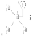
- Figure 3 shows a wireless communication system 300 including a plurality of WTRUs 310, and a base station 320. As shown in Figure 3 , the WTRUs 310 are in communication with the base station 320, and the base station 320 is in communication with a network 330. Although three WTRUs 310 and base station 320 are shown in Figure 3 , it should be noted that any combination of these wireless devices may be included in the wireless communication system 300.
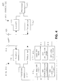
- FIG 4 is a functional block diagram 400 of the WTRU 310 and the base station 320 of the wireless communication system 300 shown in Figure 3 .
- the WTRU 310 is in communication with the base station 320.
- the WTRU 310 includes a processor 415, a receiver 416, a transmitter 417, and an antenna 418.
- the processor 415 is configured to perform the methods disclosed herein for WTRU behavior during DRX operations, in conjunction with the DRX timers: a DRX inactivity timer 410, a DRX retransmission timer 411, a DRX short cycle timer 412, a DRX long cycle timer 413, a DRX on duration timer 414, and a HARQ RTT timer 419.
- the receiver 416 and the transmitter 417 are in communication with the processor 415.
- the antenna 418 is in communication with both the receiver 416 and the transmitter 417 to facilitate the transmission and reception of wireless data.
- the base station 320 includes a processor 425, a receiver 426, a transmitter 427, and an antenna 428.
- the processor 425 is configured to allocate the WTRU access to the physical uplink shared channel (PUSCH).
- the receiver 426 and the transmitter 427 are in communication with the processor 425.
- the antenna 428 is in communication with both the receiver 426 and the transmitter 427 to facilitate the transmission and reception of wireless data.
- an uplink periodic transmission (e.g., CQI, PMI, SI and SRS, etc.) may be aligned with the start of a DRX cycle that transmits uplink periodic traffic only during a DRX on duration or active time period for either long or short DRX cycle.
- An aperiodic uplink traffic in the form of a channel quality index (CQI) report transmission, is aligned with the start of a DRX cycle.
- CQI channel quality index
- FIG. 5 shows a flowchart of a method 500 in accordance with the first embodiment in which an LTE enabled WTRU 310 aligns a CQI report transmission to the base station (eNB) 320.
- the WTRU 310 receives a request for an aperiodic CQI report from the eNB 320.
- the eNB 320 may allocate at 503 a physical uplink shared channel (PUSCH) for aperiodic CQI reporting during the on duration or active time of the next immediate short DRX cycle.
- the processor 415 of the WTRU 310 attempts at 504 to send an aperiodic CQI report in an on duration or active time during next immediate short DRX cycle.
- PUSCH physical uplink shared channel
- the processor 415 may start the DRX inactivity timer 410 at 505.
- the processor 415 maintains the DRX active period with either a long DRX cycle or a short DRX cycle, whichever is configured, and transmits the aperiodic CQI report in the allocated PUSCH during the DRX active time.
- the DRX active time period completes its cycle according to the long DRX cycle or the short DRX cycle, and the DRX inactivity timer 410 expires at the end of the DRX active time period.
- the WTRU processor 415 checks whether the CQI report is can be done within the DRX on duration. If not, then the processor 415 sets aperiodic CQI reporting to be performed during DRX active time, such that the DRX active time is long enough for the WTRU 310 to transmit a CQI report to the eNB 320 and wait for the eNB's request and allocation for an aperiodic CQI report.
- Figures 6 and 7 illustrate a second embodiment for alignment of sounding reference symbol (SRS) transmissions with a DRX cycle.
- Figure 6 shows a flowchart of a method 600, in which SRS transmissions may be aligned with the start of the long DRX cycle or short DRX cycle, whichever is configured.
- Figure 7 shows alignment of SRS transmissions SRS1, SRS2 and SRS3 with DRX on durations 701 of a short DRX cycle (SDC), or DRX on durations 702, DRX active time period 703 of a long DRX cycle (LDC).
- SDC short DRX cycle
- LDC long DRX cycle
- the processor 415 aligns the SRS with short DRX cycles and transmits the SRS during on duration or active time of short DRX cycles.
- an SRS may have a transmission period that spans multiple short DRX cycles.
- SRS1 has a transmission period of two short DRX cycles (SDC).
- the processor 415 checks condition 603 for whether only the long DRX cycle is configured.
- LDC long DRX cycle
- SRS2 and SRS 3 in Figure 7 have a transmission period equal to 2(LDC), and SRS 2 is aligned with the DRX on duration 702 of the LDC, and SRS3 is aligned with the DRX active time period 703 of the LDC.
- the processor 415 determines at 606 whether some other periodic uplink traffic may be used to maintain timing of the uplink traffic. Upon determining that no such other periodic traffic is present, the processor 415 prohibits the SRS transmission at 608 since a DRX cycle alignment is not possible. Otherwise at condition 606, the processor 415 aligns the uplink timing using the other uplink traffic, and aligns the SRS transmission during DRX on durations or active time of long DRX cycles at 607.
- the processor 415 may determine that the SRS transmission period is shorter than the long DRX cycle, and the processor 415 then checks at 606 whether there is no other uplink periodic traffic to maintain the uplink timing advance. With no other periodic uplink traffic, the processor 415 prohibits the SRS transmission at 608 since there is no way to align with the DRX on duration or DRX active time period. Otherwise at condition 606, the processor 415 aligns uplink timing advance using the other periodic uplink traffic, and transmits the SRS during on duration or active time of the long DRX cycle at 607.
- the WTRU processor 415 controls alignment of the DRX cycle with silence descriptor (SID) packets for voice over internet protocol (VoIP) during a voice silent period.
- SID silence descriptor
- VoIP voice over internet protocol
- the dynamic scheduling of resource allocations for SIP packets may be aligned with the DRX on duration or active time period whether it is a short or a long DRX cycle, such that scheduling and transmission of SID packets happen in DRX on duration or active time period.
- a short DRX cycle does not need to be activated and the WTRU processor 415 activates a long DRX cycle operation.
- the WTRU processor 415 activates a long DRX cycle. This aligns the next DRX on duration or DRX active time period with subsequent SID packets that have a periodic transmission equal to the long DRX cycle. As such, the WTRU 310 does not need to wake up at other moments to monitor and detect SID packets.
- the WTRU may first enter a short DRX cycle and then enter a long DRX cycle.
- the WTRU processor 415 triggers a short DRX cycle.
- the processor 415 starts a long DRX cycle.
- Figure 8 illustrates a scheduling request for an uplink SID packet during a VoIP silent period 803 in the uplink between talk spurts 802 and 804.
- the WTRU 310 may send a scheduling request and buffer status report for an uplink SID packet during DRX on duration or active time period 805 by transmitting uplink SID packets 801 when the DRX inactivity timer 410 is running.
- the eNB 320 sends a resource allocation for the uplink SID to the WTRU 310 within the same DRX on duration or active time period 805.
- the WTRU 310 then transmits the uplink SID packet from the allocated resource. While described here in this example as uplink transmission of an SID packet, this procedure may be applied to any uplink transmission.
- uplink SID packets 801 are sent by the WTRU 310 during DRX on duration or active time period 805
- the short DRX cycle does not need to be activated and the WTRU processor 415 selects the long DRX cycle operation.
- the WTRU processor 415 activates a long DRX cycle.
- the WTRU 310 may enter a short DRX cycle first and then enter a long DRX cycle.
- the WTRU 310 may receive a MAC control element from the eNB 320 for terminating any timer related to uplink transmission during the DRX cycle (e.g., the DRX inactivity timer 410, the DRX retransmission timer 411, the DRX short cycle timer 412, the DRX long cycle timer 413, the DRX on duration timer 414). If a resource release message is received from the eNB 320, the WTRU 310 may enter a long DRX cycle.
- a timer related to uplink transmission during the DRX cycle e.g., the DRX inactivity timer 410, the DRX retransmission timer 411, the DRX short cycle timer 412, the DRX long cycle timer 413, the DRX on duration timer 414.
- operation of the WTRU 310 and interaction of the DRX cycle timers are defined.
- the WTRU processor 415 may stop any of these running timers and terminate any on-going downlink and uplink transmissions.
- the WTRU processor 415 may then start the next DRX cycle timer (DRX short cycle timer 412 or DRX long cycle timer 413).
- the WTRU processor 415 may keep the DRX inactivity timer 410, HARQ RTT timer 419 or DRX retransmission timer 411 running and finish any on-going downlink and uplink transmission or retransmissions.
- the DRX on duration timer 414 for the next DRX cycle may be triggered by the processor 415 regardless of whether there are timers from a previous DRX cycle running into the next DRX cycle,
- ROM read only memory
- RAM random access memory
- register cache memory
- semiconductor memory devices magnetic media such as internal hard disks and removable disks, magneto-optical media, and optical media such as CD-ROM disks, and digital versatile disks (DVDs).
- Suitable processors include, by way of example, a general purpose processor, a special purpose processor, a conventional processor, a digital signal processor (DSP), a plurality of microprocessors, one or more microprocessors in association with a DSP core, a controller, a microcontroller, Application Specific Integrated Circuits (ASICs), Field Programmable Gate Arrays (FPGAs) circuits, any other type of integrated circuit (IC), and/or a state machine.
- DSP digital signal processor
- ASICs Application Specific Integrated Circuits
- FPGAs Field Programmable Gate Arrays
- a processor in association with software may be used to implement a radio frequency transceiver for use in a wireless transmit receive unit (WTRU), user equipment (UE), terminal, base station, radio network controller (RNC), or any host computer.
- the WTRU may be used in conjunction with modules, implemented in hardware and/or software, such as a camera, a video camera module, a videophone, a speakerphone, a vibration device, a speaker, a microphone, a television transceiver, a hands free headset, a keyboard, a Bluetoath® module, a frequency modulated (FM) radio unit, a liquid crystal display (LCD) display unit, an organic light-emitting diode (OLED) display unit, a digital music player, a media player, a video game player module, an Internet browser, and/or any wireless local area network (WLAN) or Ultra Wide Band (UWB) module.
- WLAN wireless local area network
- UWB Ultra Wide Band
Landscapes
- Engineering & Computer Science (AREA)
- Signal Processing (AREA)
- Computer Networks & Wireless Communication (AREA)
- Quality & Reliability (AREA)
- Mobile Radio Communication Systems (AREA)
- Transceivers (AREA)
- Telephone Function (AREA)
Abstract
Description
- This application is related to wireless communications.
- In the Third Generation Partnership Project (3GPP), discontinuous reception (DRX) is used between the network and a User Equipment (UE) to save the power of the UE. The UE may be configured by a radio resource control/media access control (RRC/MAC) with a DRX functionality that allows it to stop monitoring the packet data control channel (PDCCH) for a period of time (i.e., a sleep period). The DRX functionality consists of a long DRX cycle, a DRX inactivity timer, and a DRX retransmission timer. The DRX functionality optionally includes a short DRX cycle and a DRX short cycle timer, which are all defined in the 3GPP specification. The long DRX cycle provides a longer sleep period for the UE than does the short DRX cycle. For example, a long DRX cycle may be 160 ms, while a short DRX cycle may be 80 ms.
- The active time period is defined as the time period that the UE is awake. When DRX is configured by higher layer, this includes the on duration, the time the UE is continuously monitoring the physical downlink control channel (PDCCH) while the DRX inactivity timer has not expired, and the time that the UE is continuously monitoring the PDCCH while a DRX retransmission timer is running.
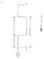
- As shown in
Figure 1 , the DRX cycle specifies the periodic repetition of the on duration followed by a possible period of inactivity. The DRX inactivity timer specifies the number of consecutive transmission time intervals (TTIs) during which the UE monitors the PDCCH after successfully decoding a PDCCH transmission which indicates an initial uplink or downlink user data transmission for the UE. This DRX inactivity timer is restarted if a new PDCCH transmission is detected while the timer is still running. Expiration of the DRX inactivity timer indicates that a particular duration of inactivity has elapsed for receiving any PDCCH transmission. The DRX retransmission timer specifies the maximum number of consecutive TTIs the UE monitors the PDCCH when a downlink retransmission is expected by the UE. The DRX short cycle timer specifies a number of consecutive TTIs that the UE shall follow the short DRX cycle after the DRX inactivity timer has expired. The hybrid automatic repeat-request (HARQ) round-trip time (RTT) timer specifies the minimum amount of TTIs before a downlink HARQ retransmission is expected by the UE. The DRX on duration timer specifies the number of consecutive TTIs during which the UE monitors the PDCCH for possible allocations. The DRX on duration is a part of a DRX cycle. - As mentioned above, the UE may be configured by the RRC/MAC with a DRX functionality that allows it to stop monitoring PDCCH during some period of time. Regardless of whether the UE is monitoring PDCCH, the UE receives and transmits HARQ feedback when such is expected.
-
Figure 2 illustrates an example DRX cycle timing diagram for demonstrating the interworking of the various DRX timers during the selection of a short DRX cycle or a long DRX cycle. As shown inFigure 2 , an initial DRXinactivity timer start 201 can occur during any subframe or TTI within the DRX on duration. The DRXinactivity timer duration 202 is fixed. An initial start of the first DRX inactivity timer occurs at 201, with any number of DRX inactivity timer restarts 203 as may be required. The DRX short cycle timer may be configured to start when the DRX inactivity timer expires. - A method and apparatus are disclosed for a wireless transmit/receive unit (WTRU) behavior during discontinuous reception (DRX) operations related to channel quality indicator (CQI) and sounding reference symbol (SRS) transmissions. In another embodiment, a method and apparatus are disclosed for a WTRU behavior during uplink and downlink VoIP silent periods in DRX operation.
- A more detailed understanding may be had from the following description, given by way of example in conjunction with the accompanying drawings wherein:
-
Figure 1 shows a DRX cycle in accordance with the prior art; -
Figure 2 shows a relationship between several DRX timers in accordance with the prior art; -
Figure 3 shows an example wireless communication system including a plurality of wireless transmit/receive units (WTRUs) and a base station; -
Figure 4 is a functional block diagram of a WTRU and the base station ofFigure 3 ; -
Figure 5 shows method flow chart for DRX operations related to CQI transmissions; -
Figure 6 shows method flow chart for DRX operations related to SRS transmissions; -
Figure 7 shows a timing diagram of SRS transmissions of various periodicities with respect to DRX cycle alignment; and -
Figure 8 shows a silence descriptor (SID) transmission during a VoIP silence period with respect to short and long DRX cycle selection. - When referred to hereafter, the terminology "wireless transmit/receive unit (WTRU)" includes but is not limited to a user equipment (UE), a mobile station, a fixed or mobile subscriber unit, a pager, a cellular telephone, a personal digital assistant (PDA), a computer, or any other type of user device capable of operating in a wireless environment. When referred to hereafter, the terminology "base station" includes but is not limited to a Node-B, an evolved Node-B (eNB), a site controller, an access point (AP), or any other type of interfacing device capable of operating in a wireless environment.
-
Figure 3 shows awireless communication system 300 including a plurality of WTRUs 310, and abase station 320. As shown inFigure 3 , the WTRUs 310 are in communication with thebase station 320, and thebase station 320 is in communication with anetwork 330. Although three WTRUs 310 andbase station 320 are shown inFigure 3 , it should be noted that any combination of these wireless devices may be included in thewireless communication system 300. -
Figure 4 is a functional block diagram 400 of the WTRU 310 and thebase station 320 of thewireless communication system 300 shown inFigure 3 . As shown inFigure 4 , the WTRU 310 is in communication with thebase station 320. In addition to the components that may be found in a typical WTRU, the WTRU 310 includes aprocessor 415, areceiver 416, atransmitter 417, and an antenna 418. Theprocessor 415 is configured to perform the methods disclosed herein for WTRU behavior during DRX operations, in conjunction with the DRX timers: aDRX inactivity timer 410, aDRX retransmission timer 411, a DRXshort cycle timer 412, a DRXlong cycle timer 413, a DRX onduration timer 414, and aHARQ RTT timer 419. Thereceiver 416 and thetransmitter 417 are in communication with theprocessor 415. The antenna 418 is in communication with both thereceiver 416 and thetransmitter 417 to facilitate the transmission and reception of wireless data. - In addition to the components that may be found in a typical base station, the
base station 320 includes aprocessor 425, areceiver 426, atransmitter 427, and anantenna 428. Theprocessor 425 is configured to allocate the WTRU access to the physical uplink shared channel (PUSCH). Thereceiver 426 and thetransmitter 427 are in communication with theprocessor 425. Theantenna 428 is in communication with both thereceiver 426 and thetransmitter 427 to facilitate the transmission and reception of wireless data. - In a first embodiment, an uplink periodic transmission (e.g., CQI, PMI, SI and SRS, etc.) may be aligned with the start of a DRX cycle that transmits uplink periodic traffic only during a DRX on duration or active time period for either long or short DRX cycle. An aperiodic uplink traffic, in the form of a channel quality index (CQI) report transmission, is aligned with the start of a DRX cycle.
-
Figure 5 shows a flowchart of amethod 500 in accordance with the first embodiment in which an LTE enabled WTRU 310 aligns a CQI report transmission to the base station (eNB) 320. At 501, the WTRU 310 receives a request for an aperiodic CQI report from the eNB 320. On thecondition 502 that a short DRX cycle is configured and that the short DRX cycle is shorter than a configured threshold, the eNB 320 may allocate at 503 a physical uplink shared channel (PUSCH) for aperiodic CQI reporting during the on duration or active time of the next immediate short DRX cycle. Theprocessor 415 of the WTRU 310 attempts at 504 to send an aperiodic CQI report in an on duration or active time during next immediate short DRX cycle. - Alternatively at 503, the
processor 415 may start theDRX inactivity timer 410 at 505. At 506, theprocessor 415 maintains the DRX active period with either a long DRX cycle or a short DRX cycle, whichever is configured, and transmits the aperiodic CQI report in the allocated PUSCH during the DRX active time. The DRX active time period completes its cycle according to the long DRX cycle or the short DRX cycle, and theDRX inactivity timer 410 expires at the end of the DRX active time period. - At 507, the
WTRU processor 415 checks whether the CQI report is can be done within the DRX on duration. If not, then theprocessor 415 sets aperiodic CQI reporting to be performed during DRX active time, such that the DRX active time is long enough for theWTRU 310 to transmit a CQI report to theeNB 320 and wait for the eNB's request and allocation for an aperiodic CQI report. -
Figures 6 and7 illustrate a second embodiment for alignment of sounding reference symbol (SRS) transmissions with a DRX cycle.Figure 6 shows a flowchart of amethod 600, in which SRS transmissions may be aligned with the start of the long DRX cycle or short DRX cycle, whichever is configured.Figure 7 shows alignment of SRS transmissions SRS1, SRS2 and SRS3 with DRX ondurations 701 of a short DRX cycle (SDC), or DRX ondurations 702, DRXactive time period 703 of a long DRX cycle (LDC). At 601, if both long and short DRX cycles are configured and SRS period is greater or equal to short DRX cycle, then at 602, theprocessor 415 aligns the SRS with short DRX cycles and transmits the SRS during on duration or active time of short DRX cycles. As shown by SRS1 inFigure 7 , an SRS may have a transmission period that spans multiple short DRX cycles. In this example, SRS1 has a transmission period of two short DRX cycles (SDC). Alternatively to thecondition 601 that both long and short DRX cycles are configured, theprocessor 415checks condition 603 for whether only the long DRX cycle is configured. If so, then acondition 604 is checked for whether the SRS transmission period is longer than the long DRX cycle (LDC), and atcondition 605, theprocessor 415 determines whether the SRS transmission period is an integer n multiple of the long DRX cycle:
Uponaffirmative conditions processor 415 aligns the SRS transmission with the long DRX cycle, and transmits the SRS during on duration or active time of long DRX cycles at 607. For example, SRS2 and SRS 3 inFigure 7 have a transmission period equal to 2(LDC), and SRS 2 is aligned with the DRX onduration 702 of the LDC, and SRS3 is aligned with the DRXactive time period 703 of the LDC.
For the condition that SRS period is not an integer multiple of the LDC at 605, theprocessor 415 determines at 606 whether some other periodic uplink traffic may be used to maintain timing of the uplink traffic. Upon determining that no such other periodic traffic is present, theprocessor 415 prohibits the SRS transmission at 608 since a DRX cycle alignment is not possible. Otherwise atcondition 606, theprocessor 415 aligns the uplink timing using the other uplink traffic, and aligns the SRS transmission during DRX on durations or active time of long DRX cycles at 607. - Returning to
condition 604, theprocessor 415 may determine that the SRS transmission period is shorter than the long DRX cycle, and theprocessor 415 then checks at 606 whether there is no other uplink periodic traffic to maintain the uplink timing advance. With no other periodic uplink traffic, theprocessor 415 prohibits the SRS transmission at 608 since there is no way to align with the DRX on duration or DRX active time period. Otherwise atcondition 606, theprocessor 415 aligns uplink timing advance using the other periodic uplink traffic, and transmits the SRS during on duration or active time of the long DRX cycle at 607. - In a third embodiment, the
WTRU processor 415 controls alignment of the DRX cycle with silence descriptor (SID) packets for voice over internet protocol (VoIP) during a voice silent period. For a downlink, the dynamic scheduling of resource allocations for SIP packets may be aligned with the DRX on duration or active time period whether it is a short or a long DRX cycle, such that scheduling and transmission of SID packets happen in DRX on duration or active time period. - In a first example for this embodiment, in which the
WTRU 310 receives downlink SID packets during DRX on duration or active time period, a short DRX cycle does not need to be activated and theWTRU processor 415 activates a long DRX cycle operation. On a condition that a DRX onduration timer 414 orDRX inactivity timer 410 expires following theWTRU 310 having received downlink SID packets during the DRX active time period, theWTRU processor 415 activates a long DRX cycle. This aligns the next DRX on duration or DRX active time period with subsequent SID packets that have a periodic transmission equal to the long DRX cycle. As such, theWTRU 310 does not need to wake up at other moments to monitor and detect SID packets. - Alternatively, as a second example, the WTRU may first enter a short DRX cycle and then enter a long DRX cycle. On a condition that a DRX on
duration timer 414 orDRX inactivity timer 410 expires after downlink SID packets is received during this period, theWTRU processor 415 triggers a short DRX cycle. In response to the shortDRX cycle timer 412 expiration, theprocessor 415 starts a long DRX cycle. -
Figure 8 illustrates a scheduling request for an uplink SID packet during a VoIPsilent period 803 in the uplink between talk spurts 802 and 804. TheWTRU 310 may send a scheduling request and buffer status report for an uplink SID packet during DRX on duration oractive time period 805 by transmittinguplink SID packets 801 when theDRX inactivity timer 410 is running. In response to the SID scheduling request, theeNB 320 sends a resource allocation for the uplink SID to theWTRU 310 within the same DRX on duration oractive time period 805. TheWTRU 310 then transmits the uplink SID packet from the allocated resource. While described here in this example as uplink transmission of an SID packet, this procedure may be applied to any uplink transmission. - In a first example, where
uplink SID packets 801 are sent by theWTRU 310 during DRX on duration oractive time period 805, the short DRX cycle does not need to be activated and theWTRU processor 415 selects the long DRX cycle operation. Thus, on the condition that the DRX onduration timer 414 orDRX inactivity timer 410 expires and theWTRU 310 sends uplink periodic packets (e.g., SID packets) during this period, theWTRU processor 415 activates a long DRX cycle. - Alternatively, on the condition that the DRX on
duration timer 414 orDRX inactivity timer 410 expires and SID packets are sent by theWTRU 310 during DRX active time period, theWTRU 310 may enter a short DRX cycle first and then enter a long DRX cycle. - The
WTRU 310 may receive a MAC control element from theeNB 320 for terminating any timer related to uplink transmission during the DRX cycle (e.g., theDRX inactivity timer 410, theDRX retransmission timer 411, the DRXshort cycle timer 412, the DRXlong cycle timer 413, the DRX on duration timer 414). If a resource release message is received from theeNB 320, theWTRU 310 may enter a long DRX cycle. - In a fourth embodiment, operation of the
WTRU 310 and interaction of the DRX cycle timers are defined. When theDRX inactivity timer 410,HARQ RTT timer 419 orDRX retransmission timer 411 is still running and a current DRXshort cycle timer 412 or DRXlong cycle timer 413 expires, theWTRU processor 415 may stop any of these running timers and terminate any on-going downlink and uplink transmissions. TheWTRU processor 415 may then start the next DRX cycle timer (DRXshort cycle timer 412 or DRX long cycle timer 413). Alternatively, theWTRU processor 415 may keep theDRX inactivity timer 410,HARQ RTT timer 419 orDRX retransmission timer 411 running and finish any on-going downlink and uplink transmission or retransmissions. The DRX onduration timer 414 for the next DRX cycle may be triggered by theprocessor 415 regardless of whether there are timers from a previous DRX cycle running into the next DRX cycle, -
- 1. A method of discontinuous reception (DRX) operation in a wireless transmit receive unit (WTRU), the method comprising aligning an uplink (UL) transmission with a DRX cycle.
- 2. The method as in
embodiment 1, further comprising transmitting sounding reference signals (SRS) during a DRX active time period. - 3. The method as in
embodiment 1 or 2, further comprising aligning a channel quality index (CQI) report transmission with a DRX cycle start. - 4. The method as in any one preceding embodiment further comprising receiving from an e Node B (eNB) an allocation of a physical uplink shared channel (PUSCH) for a channel quality index (CQI) reporting for a short DRX cycle, wherein the short DRX cycle is shorter than a configured threshold.
- 5. The method as in embodiment 4, further comprising the WTRU sending aperiodic CQI reports in a DRX active time period.
- 6. The method as in any one preceding embodiment further comprising receiving a CQI request from an eNB, and starting an inactivity timer.
- 7. The method as in embodiment 6, further comprising the WTRU operating in a DRX active period and transmitting the aperiodic CQI report in a PUSCH.
- 8. The method as in any one preceding embodiment further comprising, aligning CQI reporting with a DRX active time period, wherein the active period has a length sufficient for the WTRU to transmit the CQI report and receive a request and allocation for an aperiodic CQI report.
- 9. The method as in any one preceding embodiment further comprising aligning SRS transmissions with a start of a DRX cycle.
- 10. The method as in embodiment 9, further comprising configuring a long and a short DRX cycle and aligning the SRS with the short DRX cycle.
- 11. The method as in embodiment 9 or 10, further comprising transmitting one SRS transmission period over multiple short DRX cycles and transmitting the SRS during a short DRX cycle active period.
- 12. The method as in any one preceding embodiment further comprising configuring a short DRX cycle, determining a periodicity of the SRS, comparing the DRX cycle to the SRS period and transmitting SRS based on the comparison.
- 13. The method as in any one preceding embodiment, further comprising configuring a long DRX cycle, determining the SRS transmission period and aligning SRS with the DRX cycle, and transmitting SRS during a DRX active period based on a comparison of an SRS period to the DRX cycle length.
- 14. The method as in any one preceding embodiment, further comprising configuring a long DRX cycle, determining the SRS transmission period and aligning SRS with the DRX cycle and transmitting SRS based on a comparison of SRS period to DRX cycle length and periodic UL periodic traffic.
- 15. The method as in any one preceding embodiment, further comprising aligning a dynamic scheduling of resource allocation for system identifier (SID) packets during a voice silent period in a downlink (DL) signal with the DRX active period.
- 16. The method as in any one preceding embodiment, further comprising scheduling and transmitting SID packets during DRX active time periods.
- 17. The method as in any one preceding embodiment, further comprising receiving SID packets during the DRX active time period, and operating the WTRU in a long DRX cycle.
- 18. The method as in embodiment 17, further comprising determining the expiration of a timer, receiving a downlink SID packet and entering a long DRX cycle.
- 19. The method as in embodiment 17, further comprising the WTRU entering a short DRX cycle during a first time period and the WTRU entering a long DRX cycle during a second time period.
- 20. The method as in embodiment 19 further comprising, determining the expiration of a DRX timer, receiving a DL SID packet, entering a short cycle, and entering a long DRX cycle when a short DRX cycle timer expires.
- 21. The method as in any one preceding embodiment, further comprising aligning a scheduling request for an UL SID packet with a DRX active time period during a voice silent periods in the UL.
- 22. The method as in embodiment 21, further comprising the WTRU transmitting a SR/BSR signal for an UL SID packet during the DRX active time period and transmitting an UL SID packet when the inactivity timer is running during an UL transmission.
- 23. The method as in any one preceding embodiment, further comprising receiving SID packets during the DRX active period, and operating in a long DRX cycle.
- 24. The method as in any one preceding embodiment, further comprising determining the expiration of a DRX timer, receiving UL periodic packets, and entering a long DRX cycle.
- 25. The method as in any one preceding embodiment, further comprising receiving SID packets during the DRX active period, entering a short DRX cycle during a first time period, and entering a long DRX cycle during a later time period.
- 26. The method as in embodiment 25, further comprising, monitoring a DRX timer, receiving UL periodic packets, and entering a short DRX cycle.
- 27. The method as in embodiment 26, further comprising entering a long DRX cycle when the short DRX cycle timer expires.
- 28. The method as in any one preceding embodiment, further comprising receiving a medium access control (MAC) control element, and terminating an UL transmission DRX cycle timer in response to the received control element.
- 29. The method as in any one preceding embodiment, further comprising the WTRU receiving a resource release message, and entering a long DRX cycle.
- 30. The method as in any one preceding embodiment, further comprising detecting a DRX inactivity timer, HARQ RTT timer or DRX retransmission timer, detecting the expiration of a current DRX timer, stopping the timers, terminating DL and UL transmissions, and starting a new DRX cycle timer.
- 31. The method as in any one preceding embodiment, further comprising detecting a DRX inactivity timer, HARQ RTT timer or DRX retransmission timer, detecting the expiration of a current DRX timer, and completing DL and UL transmissions.
- 32. The method as in embodiment 31, further comprising triggering a DRX timer for a subsequent DRX cycle.
- 33. A wireless transmit receive unit (WTRU) configured to perform the method as in any one of embodiments 1-32.
- Although features and elements are described above in particular combinations, each feature or element can be used alone without the other features and elements or in various combinations with or without other features and elements. The methods or flow charts provided herein may be implemented in a computer program, software, or firmware incorporated in a computer-readable storage medium for execution by a general purpose computer or a processor. Examples of computer-readable storage mediums include a read only memory (ROM), a random access memory (RAM), a register, cache memory, semiconductor memory devices, magnetic media such as internal hard disks and removable disks, magneto-optical media, and optical media such as CD-ROM disks, and digital versatile disks (DVDs).
- Suitable processors include, by way of example, a general purpose processor, a special purpose processor, a conventional processor, a digital signal processor (DSP), a plurality of microprocessors, one or more microprocessors in association with a DSP core, a controller, a microcontroller, Application Specific Integrated Circuits (ASICs), Field Programmable Gate Arrays (FPGAs) circuits, any other type of integrated circuit (IC), and/or a state machine.
- A processor in association with software may be used to implement a radio frequency transceiver for use in a wireless transmit receive unit (WTRU), user equipment (UE), terminal, base station, radio network controller (RNC), or any host computer. The WTRU may be used in conjunction with modules, implemented in hardware and/or software, such as a camera, a video camera module, a videophone, a speakerphone, a vibration device, a speaker, a microphone, a television transceiver, a hands free headset, a keyboard, a Bluetoath® module, a frequency modulated (FM) radio unit, a liquid crystal display (LCD) display unit, an organic light-emitting diode (OLED) display unit, a digital music player, a media player, a video game player module, an Internet browser, and/or any wireless local area network (WLAN) or Ultra Wide Band (UWB) module.
- A1. A method implemented by a wireless transmit receive unit (WTRU) for aligning uplink transmissions with a discontinuous reception (DRX) cycle, comprising:
- receiving from an eNB a request for an uplink transmission;
- determining that the DRX cycle configuration is for a DRX cycle of a first length;
- receiving an uplink channel allocation for the uplink transmission, the allocation having timing aligned with a DRX on duration period or a DRX active time period of the DRX cycle of the first length; and
- sending the uplink transmission during the DRX on duration period or the DRX active time period.
- A2. The method as in embodiment A1, wherein the uplink transmission is aperiodic.
- A3. The method as in embodiment A1, wherein the uplink transmission is a channel quality indicator (CQI) report.
- A4. The method as in embodiment A3, further comprising receiving an allocation of a physical uplink shared channel (PUSCH) for the CQI report for the DRX cycle of the first length, on the condition that the DRX cycle is shorter than a configured threshold.
- A5. The method as in embodiment A3, further comprising receiving a CQI request from an eNB and starting an inactivity timer.
- A6. The method as in embodiment A3, further comprising setting the DRX active time period to a length sufficient for transmitting the CQI report and receiving a request and allocation for an aperiodic CQI report.
- A7. The method as in embodiment A1, wherein the uplink transmission is periodic.
- A8. The method as in embodiment A7, wherein the uplink transmission a sounding reference symbol (SRS) transmission.
- A9. The method as in embodiment A8, further comprising comparing the length of the DRX cycle of the first length to the SRS transmission period and sending the SRS transmission on a condition that a the SRS transmission period is greater than or equal to the length of the DRX cycle of the first length.
- A10. The method as in embodiment A7, further comprising configuring a DRX cycle of a second length that is longer than the first length, determining the SRS transmission period and aligning SRS with the DRX cycle of the second length, and sending the SRS transmission during a DRX active time period on a condition that the SRS transmission period equals an integer multiple of the length of the DRX cycle of the second length.
- A11. A method for aligning a DRX cycle with a silence identifier (SID) packet transmission of a wireless communication, comprising:
- receiving a plurality of SID packets during a VoIP silent period;
- activating a long DRX cycle on a condition that a DRX on duration timer or a DRX inactivity timer has expired; and
- aligning the long DRX cycle with subsequently received SID packets in a downlink signal.
- A12. A method for aligning a DRX cycle with a silence identifier (SID) packet transmission of a wireless communication, comprising:
- sending a scheduling request for an uplink SID transmission, the scheduling request sent during a DRX on duration or a DRX active time period of a DRX cycle;
- receiving an allocation for the uplink SID transmission during the DRX on duration or the DRX active time period;
- activating a long DRX cycle on a condition that a DRX on duration timer or a DRX inactivity timer has expired; and
- aligning the long DRX cycle with subsequently sent uplink SID transmission.
- A13. A wireless transmit/receive unit (WTRU), comprising:
- a processor configured to receive a request for an uplink transmission;
- determine that a discontinuous reception (DRX) cycle configuration is for a DRX cycle of a first length; receive an uplink channel allocation for the uplink transmission, the allocation having timing aligned with a DRX on duration period or a DRX active time period of th DRX cycle of the first length; and send the uplink transmission during the DRX on duration period or the DRX active time period.
- A14. The WTRU as in embodiment A13, wherein the uplink transmission is aperiodic.
- A15. The WTRU as in embodiment A13, wherein the uplink transmission is a channel quality indicator (CQI) report.
- A16. The WTRU as in embodiment A15, further comprising receiving an allocation of a physical uplink shared channel (PUSCH) for the CQI report for the DRX cycle of the first length, on the condition that the DRX cycle length is shorter than a configured threshold.
- A17. The WTRU as in embodiment A15, further comprising receiving a CQI request from an eNB and starting an inactivity timer.
- A18. The WTRU as in embodiment A15, further comprising setting the DRX active time period to a length sufficient for transmitting the CQI report and receiving a request and allocation for an aperiodic CQI report.
- A19. The WTRU as in embodiment A13, wherein the uplink transmission is periodic.
- A20. The WTRU as in embodiment A19, wherein the uplink transmission a sounding reference symbol (SRS) transmission.
- A21. The WTRU as in embodiment A20, wherein the processor is further configured to determine a SRS transmission period, compare the DRX cycle length to the SRS transmission period, and send the SRS transmission on a condition that the DRX cycle length is greater than or equal to the SRS transmission period.
- A22. The WTRU as in embodiment A18, wherein the processor is further configured to configure a DRX cycle of a second length, determine the SRS transmission period and align the SRS with the DRX cycle, and transmit the SRS during a DRX active time period on a condition that the SRS transmission period equals an integer multiple of the length of the DRX cycle of the second length.
- A23. A WTRU for aligning a DRX cycle with a silence identifier (SID) packet transmission of a wireless communication, comprising:
- a processor configured to receive a plurality of SID packets during a VoIP silent period; activate a long DRX cycle on a condition that a DRX on duration timer or a DRX inactivity timer has expired; and align the long DRX cycle with subsequently received SID packets in a downlink signal.
- A24. A WTRU for aligning a DRX cycle with a silence identifier (SID) packet transmission of a wireless communication, comprising:
- a processor configured to send a scheduling request for an uplink SID transmission, the scheduling request sent during a DRX on duration or a DRX active time period of a DRX cycle; receive an allocation for the uplink SID transmission during the DRX on duration or the DRX active time period; activate a long DRX cycle on a condition that a DRX on duration timer or a DRX inactivity timer has expired; and align the long DRX cycle with subsequently sent uplink SID transmission.
Claims (14)
- A method implemented by a wireless transmit receive unit, WTRU, for aligning uplink transmissions with a discontinuous reception, DRX, cycle, comprising:determining that the DRX cycle is a DRX cycle of a first length;receiving a configuration that includes one or more uplink channel allocation opportunities for a periodic uplink transmission, the one or more uplink channel allocation opportunities based upon at least one of: a DRX on-duration period of the DRX cycle of the first length or a DRX active time period of the DRX cycle of the first length; andsending the periodic uplink transmission at least one of the one or more uplink channel allocation opportunities.
- The method of claim 1, wherein the periodic uplink transmission is a channel quality indicator, CQI, report.
- The method of claim 2, further comprising receiving an allocation opportunity of a physical uplink shared channel, PUSCH, for the CQI report on the condition that the DRX cycle of the first length is shorter than a configured threshold.
- The method of claim 2, further comprising receiving a CQI request from an evolved-nodeB, Enb, and starting an inactivity timer.
- The method of claim 2, further comprising setting the DRX active time period to a length sufficient for transmitting the CQI report.
- The method of claim 1, wherein the uplink transmission is a sounding reference symbol, SRS, transmission.
- The method of claim 6, further comprising comparing the length of the DRX cycle of the first length to a SRS transmission period and sending the SRS transmission on a condition that the length of the DRX cycle of the first length is greater than or equal to the SRS transmission period.
- A wireless transmit/receive unit, WTRU, comprising:a processor configured to:determine that a discontinuous reception, DRX, cycle is a DRX cycle of a first length;receive a configuration including one or more uplink channel allocation opportunities for a periodic uplink transmission, the one or more uplink channel allocation opportunities based upon at least one of: a DRX on-duration period of the DRX cycle of the first length or a DRX active time period of the DRX cycle of the first length; andsend the periodic uplink transmission at least one of the one or more uplink channel allocation opportunities.
- The WTRU of claim 8, wherein the periodic uplink transmission is a channel quality indicator, CQI, report.
- The WTRU of claim 9, wherein the processor is further configured to receive an allocation opportunity of a physical uplink shared channel, PUSCH, for the CQI report on the condition that the DRX cycle of the first length is shorter than a configured threshold.
- The WTRU of claim 9, wherein the processor is further configured to receive a CQI request from an eNB and start an inactivity timer.
- The WTRU of claim 9, wherein the processor is further configured to set the DRX active time period to a length sufficient for transmitting the CQI report.
- The WTRU of claim 8, wherein the uplink transmission is a sounding reference symbol, SRS, transmission.
- The WTRU of claim 13, wherein the processor is further configured to determine a SRS transmission period, compare the DRX cycle of the first length to the SRS transmission period, and send the SRS transmission on a condition that the DRX cycle of the first length is greater than or equal to the SRS transmission period.
Applications Claiming Priority (2)
| Application Number | Priority Date | Filing Date | Title |
|---|---|---|---|
| US3652708P | 2008-03-14 | 2008-03-14 | |
| EP09720130A EP2263342A2 (en) | 2008-03-14 | 2009-03-13 | Lte drx cycle alignment |
Related Parent Applications (1)
| Application Number | Title | Priority Date | Filing Date |
|---|---|---|---|
| EP09720130A Division EP2263342A2 (en) | 2008-03-14 | 2009-03-13 | Lte drx cycle alignment |
Publications (1)
| Publication Number | Publication Date |
|---|---|
| EP2738969A1 true EP2738969A1 (en) | 2014-06-04 |
Family
ID=41062960
Family Applications (2)
| Application Number | Title | Priority Date | Filing Date |
|---|---|---|---|
| EP14151436.4A Withdrawn EP2738969A1 (en) | 2008-03-14 | 2009-03-13 | Coordinated uplink transmission in LTE DRX operations for a wireless transmit receive unit. |
| EP09720130A Withdrawn EP2263342A2 (en) | 2008-03-14 | 2009-03-13 | Lte drx cycle alignment |
Family Applications After (1)
| Application Number | Title | Priority Date | Filing Date |
|---|---|---|---|
| EP09720130A Withdrawn EP2263342A2 (en) | 2008-03-14 | 2009-03-13 | Lte drx cycle alignment |
Country Status (10)
| Country | Link |
|---|---|
| US (2) | US8249004B2 (en) |
| EP (2) | EP2738969A1 (en) |
| JP (2) | JP5324605B2 (en) |
| KR (3) | KR20120028402A (en) |
| CN (1) | CN101971554A (en) |
| AR (1) | AR070903A1 (en) |
| CA (1) | CA2715035C (en) |
| SG (1) | SG188894A1 (en) |
| TW (1) | TW200944026A (en) |
| WO (1) | WO2009114800A2 (en) |
Families Citing this family (115)
| Publication number | Priority date | Publication date | Assignee | Title |
|---|---|---|---|---|
| EP2806568B1 (en) | 2008-02-01 | 2015-12-30 | BlackBerry Limited | System and method for uplink timing synchronization in conjunction with discontinuous reception |
| US8249004B2 (en) * | 2008-03-14 | 2012-08-21 | Interdigital Patent Holdings, Inc. | Coordinated uplink transmission in LTE DRX operations for a wireless transmit receive unit |
| US8488521B2 (en) * | 2008-03-14 | 2013-07-16 | Interdigital Patent Holdings, Inc. | Behavior for wireless transmit/receive unit and MAC control elements for LTE DRX operations |
| US8121045B2 (en) * | 2008-03-21 | 2012-02-21 | Research In Motion Limited | Channel quality indicator transmission timing with discontinuous reception |
| ES2428223T3 (en) * | 2008-03-25 | 2013-11-06 | Telefonaktiebolaget L M Ericsson (Publ) | DRX functionality in multi-carrier wireless networks |
| US8199725B2 (en) | 2008-03-28 | 2012-06-12 | Research In Motion Limited | Rank indicator transmission during discontinuous reception |
| US8179828B2 (en) * | 2008-03-28 | 2012-05-15 | Research In Motion Limited | Precoding matrix index feedback interaction with discontinuous reception |
| ES2712916T3 (en) | 2008-04-25 | 2019-05-16 | Blackberry Ltd | Method and system for the control of discontinuous reception in a wireless network |
| CN101572896B (en) * | 2008-04-29 | 2011-01-26 | 大唐移动通信设备有限公司 | A method and device for configuring an uplink sounding reference signal |
| ES2375694T3 (en) * | 2008-04-30 | 2012-03-05 | Koninklijke Philips Electronics N.V. | METHOD FOR COMMUNICATION IN A NETWORK OF RADIO STATIONS FOR IT. |
| WO2009136830A1 (en) * | 2008-05-07 | 2009-11-12 | Telefonaktiebolaget L M Ericsson (Publ) | Discontinuous reception (drx) timer triggered with the transmission of a buffer status report (bsr) |
| WO2010018819A1 (en) * | 2008-08-11 | 2010-02-18 | 株式会社エヌ・ティ・ティ・ドコモ | Base station device and communication control method |
| KR101164117B1 (en) * | 2009-09-04 | 2012-07-12 | 엘지전자 주식회사 | Method of controlling a monitoring operation of a physical downlink channel in wireless communication system |
| US8848520B2 (en) | 2010-02-10 | 2014-09-30 | Qualcomm Incorporated | Aperiodic sounding reference signal transmission method and apparatus |
| KR101791266B1 (en) | 2010-02-12 | 2017-10-30 | 엘지전자 주식회사 | Method and apparatus of transmitting data in wireless communication system |
| KR101664279B1 (en) * | 2010-02-16 | 2016-10-12 | 삼성전자주식회사 | Controlling method and apparatus for discontinuous reception in a wireless communication system |
| US8743764B2 (en) * | 2010-02-19 | 2014-06-03 | Qualcomm Incorporated | Extending an effective control channel periodicity via discontinuous reception (DRX) |
| US8989069B2 (en) * | 2010-03-03 | 2015-03-24 | Qualcomm Incorporated | Method and apparatus for channel quality indicator (CQI) enhancements |
| US20110237266A1 (en) * | 2010-03-26 | 2011-09-29 | Research In Motion Limited | Sounding Reference Signal Transmission During Discontinuous Reception |
| US10911961B2 (en) * | 2010-03-31 | 2021-02-02 | Qualcomm Incorporated | Method and apparatus to facilitate support for multi-radio coexistence |
| JP5514954B2 (en) | 2010-04-02 | 2014-06-04 | インターデイジタル パテント ホールディングス インコーポレイテッド | Configuration and transmission of uplink sounding reference signals |
| KR101719002B1 (en) * | 2010-06-07 | 2017-03-23 | 엘지전자 주식회사 | Method and apparatus of transmitting aperiodic sounding reference signal in wireless communication system |
| CN103069907B (en) * | 2010-06-30 | 2017-05-17 | 诺基亚通信公司 | Scheduling of user terminals in communication network |
| CN102404074B (en) * | 2010-09-17 | 2014-06-18 | 电信科学技术研究院 | Transmission method and equipment of non-periodic SRS (Stimulated Raman scattering) in TDD (Time Division Duplexing) system |
| US8755295B2 (en) * | 2010-09-27 | 2014-06-17 | Htc Corporation | Apparatuses and methods for handling measurement logging configuration |
| KR20120034521A (en) * | 2010-10-01 | 2012-04-12 | 주식회사 팬택 | Method for transmitting srs in multiple component carrier system and apparatus thereof |
| KR101928448B1 (en) * | 2010-10-11 | 2018-12-13 | 삼성전자주식회사 | Method and appratus for avoiding inteference from in-device communication module using time division multiplexing in wireless communication system |
| CN102595568A (en) * | 2011-01-12 | 2012-07-18 | 华为技术有限公司 | Method, device and system for discontinuous receiving |
| KR102073027B1 (en) | 2011-04-05 | 2020-02-04 | 삼성전자 주식회사 | Method and appratus of operating multiple time alignment timer in mobile communication system using carrier aggregation |
| CN107613523B (en) | 2011-02-15 | 2021-12-28 | 三星电子株式会社 | Power headroom reporting method and device for user equipment priority |
| ES2687145T3 (en) | 2011-02-21 | 2018-10-23 | Samsung Electronics Co., Ltd. | Procedure to efficiently report the transmission power of a user equipment and device thereof |
| KR101995293B1 (en) | 2011-02-21 | 2019-07-02 | 삼성전자 주식회사 | Method and appratus of activating or deactivating secondary carriers in time division duplex mobile communication system using carrier aggregation |
| US8849215B2 (en) * | 2011-03-30 | 2014-09-30 | Amazon Technologies, Inc. | Reducing rate of detection cycles and measurement cycles in a discontinuous reception (DRX) mode |
| CN107017970B (en) | 2011-04-05 | 2020-07-14 | 三星电子株式会社 | Terminal and base station in carrier aggregation system and method thereof |
| KR20120115953A (en) | 2011-04-11 | 2012-10-19 | 삼성전자주식회사 | Method and apparatus to provide the useful information obtained by ue to enb efficiently |
| KR101948801B1 (en) | 2011-04-11 | 2019-02-18 | 삼성전자주식회사 | Data recieving method and apparatus for user equipment supporting multimedia broadcast multicast service |
| KR101929307B1 (en) * | 2011-04-11 | 2018-12-17 | 삼성전자 주식회사 | method and apparatus to control UE Cell reselection priority while UE is in CSG cell |
| KR101956213B1 (en) * | 2011-04-11 | 2019-06-24 | 삼성전자 주식회사 | Method and apparatus for transmitting uplink control signal of ue in battery saving mode in mobile communication system |
| US20120275362A1 (en) * | 2011-04-30 | 2012-11-01 | Sharp Laboratories Of America, Inc. | Devices for interference control signaling |
| WO2012153993A2 (en) | 2011-05-10 | 2012-11-15 | 삼성전자 주식회사 | Method and apparatus for applying a time alignment timer in a wireless communication system using a carrier aggregation technique |
| CN102821454B (en) * | 2011-06-10 | 2017-11-10 | 中兴通讯股份有限公司 | Terminal keeps the processing method and processing device of uplink synchronous under DRX mode |
| KR101790036B1 (en) * | 2011-07-11 | 2017-10-25 | 삼성전자 주식회사 | Method for controlling discontinuous reception in mobile terminal |
| WO2013007022A1 (en) * | 2011-07-13 | 2013-01-17 | Empire Technology Development Llc | Voice over internet protocol services |
| US9161371B2 (en) * | 2011-07-21 | 2015-10-13 | Qualcomm Incorporated | Power optimization using scheduling request delay |
| US10321419B2 (en) | 2011-08-10 | 2019-06-11 | Samsung Electronics Co., Ltd. | Method and apparatus for transmitting data using a multi-carrier in a mobile communication system |
| KR101967721B1 (en) | 2011-08-10 | 2019-04-10 | 삼성전자 주식회사 | Method and appratus of applying extended access barring in mobile communication system |
| KR102247818B1 (en) | 2011-08-10 | 2021-05-04 | 삼성전자 주식회사 | Method and apparatus for transmitting data in mobile communication system with multiple carrier |
| KR101990134B1 (en) | 2011-08-10 | 2019-06-17 | 삼성전자주식회사 | Method and apparatus for reporting capability information of dual mode user equipment |
| EP3429307B1 (en) | 2011-08-10 | 2022-06-15 | Samsung Electronics Co., Ltd. | Method and apparatus for transmitting data using a multi-carrier in a mobile communication system |
| GB2493713B (en) * | 2011-08-12 | 2013-10-23 | Renesas Mobile Corp | Method of operating a wireless device and processing system for a wireless device |
| US8755316B2 (en) * | 2011-08-15 | 2014-06-17 | Broadcom Corporation | Coordination of DRX and eICIC |
| KR102092579B1 (en) | 2011-08-22 | 2020-03-24 | 삼성전자 주식회사 | Method and apparatus for support multiple frequency band in a mobile communication system |
| EP2749081B1 (en) | 2011-08-22 | 2019-03-27 | Samsung Electronics Co., Ltd. | Method and apparatus for supporting multiple frequency bands in mobile communication system |
| KR20140084109A (en) * | 2011-09-30 | 2014-07-04 | 노키아 솔루션스 앤드 네트웍스 오와이 | Discontinuous reception |
| EP2765806B1 (en) | 2011-10-05 | 2020-09-23 | Samsung Electronics Co., Ltd. | Method and apparatus for reselecting a cell in heterogeneous networks in a wireless communication system |
| IN2014KN00783A (en) | 2011-10-10 | 2015-10-02 | Samsung Electronics Co Ltd | |
| WO2013055145A1 (en) * | 2011-10-12 | 2013-04-18 | 삼성전자 주식회사 | Method and device for transmitting reverse control signal in mobile communication system |
| EP2768171B1 (en) * | 2011-10-12 | 2022-04-13 | Samsung Electronics Co., Ltd. | Method and device for transmitting reverse control signal in mobile communication system |
| WO2013066044A1 (en) * | 2011-10-31 | 2013-05-10 | 엘지전자 주식회사 | Method for transmitting an uplink control signal, user equipment, method for receiving an uplink signal, and base station |
| KR102049794B1 (en) | 2012-01-09 | 2019-11-28 | 삼성전자 주식회사 | Method and apparatus for logging |
| US20140334371A1 (en) | 2012-01-27 | 2014-11-13 | Samsung Electronics Co., Ltd. | Method and apparatus for transmitting and receiving data by using plurality of carriers in mobile communication systems |
| US9357416B2 (en) * | 2012-01-30 | 2016-05-31 | Qualcomm Incorporated | Optimizing UE wakeup timeline in connected mode DRX based on CQI reporting schedule in a wireless communication system |
| WO2013123660A1 (en) * | 2012-02-23 | 2013-08-29 | Renesas Mobile Corporation | Aperiodical discovery channel design for small rrhs |
| CN102711263B (en) * | 2012-03-13 | 2015-07-08 | 北京邮电大学 | Multiuser uplink control signal sending method in non-continuous receiving mode |
| JP6001100B2 (en) * | 2012-03-15 | 2016-10-05 | ノキア ソリューションズ アンド ネットワークス オサケユキチュア | Configuration of carrier-related reference signal transmission |
| EP2689623B1 (en) | 2012-03-23 | 2018-10-24 | MediaTek Inc. | Methods and apparatus of allocating scheduling request resources in mobile communication networks |
| US9603091B2 (en) * | 2012-04-24 | 2017-03-21 | Telefonaktiebolaget L M Ericsson | Reducing periodic reporting in discontinuous receive (DRX) mode |
| EP2849501B1 (en) | 2012-05-09 | 2020-09-30 | Samsung Electronics Co., Ltd. | Method and apparatus for controlling discontinuous reception in mobile communication system |
| KR102064377B1 (en) | 2012-05-09 | 2020-02-12 | 삼성전자 주식회사 | Method and apparatus for transmitting and receiving measurement information in mobile communication system |
| US8879475B2 (en) * | 2012-05-15 | 2014-11-04 | Apple Inc. | Adaptive channel state feedback in discontinuous reception scenarios based on connection characteristics |
| US9374845B2 (en) | 2012-05-18 | 2016-06-21 | Qualcomm Incorporated | Method and apparatus for joint HARQ and DRX optimization for low cost MTC devices |
| CN109982378A (en) | 2012-05-21 | 2019-07-05 | 三星电子株式会社 | Method and apparatus for transmitting and receiving data in mobile communication system |
| US9456419B2 (en) * | 2012-07-12 | 2016-09-27 | Lg Electronics Inc. | Method and apparatus for applying a discontinuous reception (DRX) cycle in a wireless communication system |
| US9125209B2 (en) | 2012-07-18 | 2015-09-01 | Qualcomm Incorporated | Method to report CQI in connected-mode DRX and reduce UE wake up time for 3GPP long term evolution (LTE) systems |
| KR101451416B1 (en) * | 2012-07-26 | 2014-10-23 | 주식회사 케이티 | Method of transmitting sounding reference signal, method of receiving srs, terminal and base station |
| US9723553B2 (en) * | 2012-10-15 | 2017-08-01 | Telefonaktiebolaget Lm Ericsson (Publ) | Method, network device, computer program and computer program product for determining a set of power state parameters |
| EP2906013B1 (en) * | 2012-11-02 | 2019-01-09 | Huawei Technologies Co., Ltd. | Method and apparatus for controlling transmission of uplink signal |
| US9338070B2 (en) | 2012-11-02 | 2016-05-10 | Industrial Technology Research Institute | System and method for operating M2M devices |
| EP2782409A1 (en) * | 2013-03-20 | 2014-09-24 | Panasonic Intellectual Property Corporation of America | Deterministic UE behaviour for CSI/SRS Reporting during DRX |
| WO2014154940A1 (en) | 2013-03-26 | 2014-10-02 | Nokia Corporation | Method and apparatus for reducing uplink transmissions |
| US10313913B2 (en) * | 2013-05-09 | 2019-06-04 | Qualcomm Incorporated | Overload control and supervision for wireless devices |
| US10693613B2 (en) | 2013-06-13 | 2020-06-23 | Convida Wireless, Llc | Telecommunications apparatus and methods |
| US10085293B2 (en) | 2013-06-13 | 2018-09-25 | Sony Corporation | Telecommunications apparatus and methods |
| WO2015007304A1 (en) * | 2013-07-15 | 2015-01-22 | Huawei Technologies Co., Ltd. | Method for transmitting communication signals in a wireless communication system |
| EP4040875B1 (en) | 2013-08-09 | 2025-07-02 | Telefonaktiebolaget LM Ericsson (publ) | System information broadcast for machine-type communication |
| US9998991B2 (en) | 2013-08-28 | 2018-06-12 | Telefonaktiebolaget L M Ericsson (Publ) | Method and apparatuses for discontinuous reception cycle estimation by data packet monitoring |
| WO2015078009A1 (en) | 2013-11-29 | 2015-06-04 | 华为技术有限公司 | Method and device for reducing self-interference signal of communication system |
| WO2015161440A1 (en) * | 2014-04-22 | 2015-10-29 | 华为技术有限公司 | Method for determining configuration parameter and transmitting scheduling request and related device |
| JP2017531369A (en) * | 2014-09-26 | 2017-10-19 | インテル コーポレイション | Method and apparatus for voice data transmission |
| US10531427B2 (en) * | 2014-12-09 | 2020-01-07 | Qualcomm Incorporated | Enhanced system access for E-UTRAN |
| US10531512B2 (en) * | 2015-04-01 | 2020-01-07 | Huawei Technologies Co., Ltd. | System and method for a tracking channel |
| EP3284303B1 (en) * | 2015-04-16 | 2019-11-20 | LG Electronics Inc. | Method and apparatus for performing extended drx operation based on uplink indication in wireless communication system |
| WO2016190798A2 (en) * | 2015-05-25 | 2016-12-01 | Telefonaktiebolaget Lm Ericsson (Publ) | Radio network node, wireless device and methods performed therein |
| WO2016204519A1 (en) | 2015-06-15 | 2016-12-22 | Samsung Electronics Co., Ltd. | Method and apparatus for group communication in wireless communication system |
| US10750554B2 (en) | 2015-08-07 | 2020-08-18 | Sharp Kabushiki Kaisha | Terminal device, base station device, communication system, measurement method, and integrated circuit |
| KR102482789B1 (en) * | 2015-08-07 | 2022-12-29 | 샤프 가부시키가이샤 | Terminal equipment, base station equipment, communication systems, measurement methods and integrated circuits |
| WO2017132899A1 (en) | 2016-02-03 | 2017-08-10 | Nokia Technologies Oy | Discontinuous reception timer operation for changed tti length |
| US10477470B2 (en) * | 2016-02-08 | 2019-11-12 | Qualcomm Incorporated | Systems and methods for silent period operation during wireless communication |
| US10122559B2 (en) * | 2016-03-21 | 2018-11-06 | Qualcomm Incorporated | Uplink channel quality measurement using a subframe with high-intensity reference signal bursts |
| EP3414971B1 (en) | 2016-03-24 | 2021-02-24 | LG Electronics Inc. -1- | Method for configuring discontinuous reception in a communication system and device therefor |
| CN109565711A (en) * | 2016-08-26 | 2019-04-02 | 株式会社Ntt都科摩 | User apparatus and sending method |
| CN110121904A (en) * | 2016-09-13 | 2019-08-13 | 查尔斯M·林克二世 | Method and system for low power grid communication with machinery |
| EP3469753B1 (en) | 2017-03-23 | 2023-02-22 | LG Electronics Inc. | Method and user equipment for receiving downlink signals |
| US10524294B2 (en) * | 2017-05-04 | 2019-12-31 | Ofinno, Llc | Scheduling request transmission |
| KR102398999B1 (en) * | 2017-06-09 | 2022-05-16 | 광동 오포 모바일 텔레커뮤니케이션즈 코포레이션 리미티드 | Bandwidth configuration methods and devices |
| US11076445B2 (en) * | 2017-09-07 | 2021-07-27 | Guangdong Oppo Mobile Telecommunications Corp., Ltd. | Discontinuous reception method, terminal device and network device |
| KR102265532B1 (en) | 2017-10-25 | 2021-06-15 | 에스케이텔레콤 주식회사 | Terminal device, uplink data trasmission method |
| KR102709367B1 (en) * | 2018-06-25 | 2024-09-25 | 광동 오포 모바일 텔레커뮤니케이션즈 코포레이션 리미티드 | Wireless communication method, network device and terminal device |
| US11452165B2 (en) * | 2019-06-07 | 2022-09-20 | Qualcomm Incorporated | Discontinuous reception techniques with non-uniform cycle durations |
| US11632732B2 (en) | 2019-06-24 | 2023-04-18 | Qualcomm Incorporated | Wireless communication including XR traffic awareness |
| CN110945921B (en) * | 2019-11-07 | 2023-10-03 | 北京小米移动软件有限公司 | Method and device, equipment and medium for determining activation time of scheduled carrier |
| US12610424B2 (en) * | 2020-08-05 | 2026-04-21 | Apple Inc. | Positioning SRS transmissions during a discontinuous reception cycle |
| US12047320B2 (en) * | 2020-08-05 | 2024-07-23 | Apple Inc. | Network operations related to receiving positioning SRS transmissions |
| US20240090077A1 (en) * | 2021-01-07 | 2024-03-14 | Beijing Xiaomi Mobile Software Co., Ltd. | Discontinuous reception method and apparatus |
| US12114323B2 (en) | 2021-11-09 | 2024-10-08 | Qualcomm Incorporated | Sounding reference signal coordination for periodic traffic |
Family Cites Families (24)
| Publication number | Priority date | Publication date | Assignee | Title |
|---|---|---|---|---|
| US7929921B2 (en) * | 2003-06-10 | 2011-04-19 | Motorola Mobility, Inc. | Diversity control in wireless communications devices and methods |
| DE602004006624T2 (en) * | 2004-09-13 | 2008-01-31 | Alcatel Lucent | Estimation of the transmission quality in a radio network |
| WO2006114710A2 (en) | 2005-02-28 | 2006-11-02 | Nokia Corporation | Discontinuous transmission/reception in a communications system |
| KR101208271B1 (en) * | 2006-03-07 | 2012-12-05 | 한국전자통신연구원 | method for power saving operation of user equipment in cellular system |
| RU2395906C2 (en) * | 2006-03-24 | 2010-07-27 | Интердиджитал Текнолоджи Корпорейшн | Method and device for supporting uplink synchronisation and reducing accumulator power consumption |
| CN101411095B (en) | 2006-03-28 | 2013-06-19 | 三星电子株式会社 | Method and device for discontinuous reception of a connected terminal in a mobile communication system |
| KR100895166B1 (en) * | 2006-04-21 | 2009-05-04 | 삼성전자주식회사 | Method and apparatus for transmitting / receiving channel quality information in wireless communication system |
| WO2007145035A1 (en) * | 2006-06-16 | 2007-12-21 | Mitsubishi Electric Corporation | Mobile communication system and mobile terminal |
| US8818321B2 (en) | 2006-06-20 | 2014-08-26 | Nokia Corporation | Method and system for providing reply-controlled discontinuous reception |
| US7916675B2 (en) | 2006-06-20 | 2011-03-29 | Nokia Corporation | Method and system for providing interim discontinuous reception/transmission |
| WO2008035905A1 (en) * | 2006-09-19 | 2008-03-27 | Samsung Electronics Co., Ltd. | Method and apparatus for performing discontinuous reception operation by connected mode user equipment in a mobile communication system |
| KR101312876B1 (en) * | 2006-12-13 | 2013-09-30 | 삼성전자주식회사 | Method and apparatus for measurementing in a wireless system |
| KR20080067293A (en) * | 2007-01-15 | 2008-07-18 | 삼성전자주식회사 | Reverse data processing method and apparatus of terminal for performing discontinuous reception in mobile communication system |
| US8169957B2 (en) * | 2007-02-05 | 2012-05-01 | Qualcomm Incorporated | Flexible DTX and DRX in a wireless communication system |
| US8005107B2 (en) * | 2007-02-06 | 2011-08-23 | Research In Motion Limited | Method and system for robust MAC signaling |
| US20080268863A1 (en) * | 2007-04-30 | 2008-10-30 | Klaus Pedersen | Method and Apparatus for Reporting Channel Quality |
| EP2632210A1 (en) * | 2007-09-14 | 2013-08-28 | Research In Motion Limited | System and method for discontinuous reception control start time |
| US8031693B2 (en) * | 2007-11-20 | 2011-10-04 | Research In Motion Limited | System and method for timing synchronization |
| CN101483891B (en) * | 2008-01-08 | 2012-12-05 | 株式会社Ntt都科摩 | Method and apparatus setting activation period starting point to user equipment |
| EP2806568B1 (en) * | 2008-02-01 | 2015-12-30 | BlackBerry Limited | System and method for uplink timing synchronization in conjunction with discontinuous reception |
| US8249004B2 (en) * | 2008-03-14 | 2012-08-21 | Interdigital Patent Holdings, Inc. | Coordinated uplink transmission in LTE DRX operations for a wireless transmit receive unit |
| CN101978745B (en) * | 2008-03-19 | 2014-09-24 | 爱立信电话股份有限公司 | Method and a base station for detecting loss of synchronization |
| CN101572945B (en) * | 2008-04-29 | 2011-08-24 | 中国移动通信集团公司 | Method and device for confirming sending resource of channel quality indication |
| EP2289187B1 (en) * | 2008-06-04 | 2016-12-14 | Wireless Future Technologies Inc. | Channel quality signaling for persistent/semi-persistent radio resource allocations |
-
2009
- 2009-03-12 US US12/403,169 patent/US8249004B2/en active Active
- 2009-03-13 EP EP14151436.4A patent/EP2738969A1/en not_active Withdrawn
- 2009-03-13 KR KR1020127004437A patent/KR20120028402A/en not_active Ceased
- 2009-03-13 SG SG2013018767A patent/SG188894A1/en unknown
- 2009-03-13 WO PCT/US2009/037149 patent/WO2009114800A2/en not_active Ceased
- 2009-03-13 CA CA2715035A patent/CA2715035C/en not_active Expired - Fee Related
- 2009-03-13 JP JP2010550900A patent/JP5324605B2/en active Active
- 2009-03-13 EP EP09720130A patent/EP2263342A2/en not_active Withdrawn
- 2009-03-13 KR KR1020107023008A patent/KR20100126509A/en not_active Ceased
- 2009-03-13 CN CN2009801087207A patent/CN101971554A/en active Pending
- 2009-03-13 KR KR1020147006912A patent/KR20140042930A/en not_active Ceased
- 2009-03-16 TW TW098108420A patent/TW200944026A/en unknown
- 2009-03-16 AR ARP090100928A patent/AR070903A1/en active IP Right Grant
-
2012
- 2012-08-20 US US13/589,344 patent/US20130223311A1/en not_active Abandoned
-
2013
- 2013-07-18 JP JP2013149437A patent/JP2013236394A/en active Pending
Non-Patent Citations (5)
| Title |
|---|
| "PUCCH handling during DRX", 3GPP DRAFT; R2-081533 PUCCH HANDLING, 3RD GENERATION PARTNERSHIP PROJECT (3GPP), MOBILE COMPETENCE CENTRE ; 650, ROUTE DES LUCIOLES ; F-06921 SOPHIA-ANTIPOLIS CEDEX ; FRANCE, vol. RAN WG2, no. Shenzhen, China; 20080325, 25 March 2008 (2008-03-25), XP050139270 * |
| ERICSSON: "3GPP TSGRAN WG2 Meeting #52: Tdoc R2-060967: DRX and DTX in LTE Active", 3RD GENERATION PARTNERSHIP PROJECT (3GPP); TECHNICALSPECIFICATION GROUP (TSG) RADIO ACCESS NETWORK (RAN); WORKINGGROUP 2 (WG2), XX, XX, no. R2-060967, 27 March 2006 (2006-03-27), pages 1 - 5, XP002463498 * |
| NOKIA: "DRX parameters in LTE", 3RD GENERATION PARTNERSHIP PROJECT (3GPP); TECHNICALSPECIFICATION GROUP (TSG) RADIO ACCESS NETWORK (RAN); WORKINGGROUP 2 (WG2), XX, XX, vol. R2-071285, 26 March 2007 (2007-03-26), pages 1 - 7, XP003023549 * |
| PANASONIC: "CQI reporting during DRX operation", 3GPP DRAFT; R2-080871_CQI_DURING_DRX, 3RD GENERATION PARTNERSHIP PROJECT (3GPP), MOBILE COMPETENCE CENTRE ; 650, ROUTE DES LUCIOLES ; F-06921 SOPHIA-ANTIPOLIS CEDEX ; FRANCE, vol. RAN WG2, no. Sorrento, Italy; 20080205, 5 February 2008 (2008-02-05), XP050138684 * |
| RESEARCH IN MOTION ET AL: "Some Details on CQI Transmission during DRX", 3GPP DRAFT; R2-081866, 3RD GENERATION PARTNERSHIP PROJECT (3GPP), MOBILE COMPETENCE CENTRE ; 650, ROUTE DES LUCIOLES ; F-06921 SOPHIA-ANTIPOLIS CEDEX ; FRANCE, vol. RAN WG2, no. Shenzhen, China; 20080325, 25 March 2008 (2008-03-25), XP050139556 * |
Also Published As
| Publication number | Publication date |
|---|---|
| JP2013236394A (en) | 2013-11-21 |
| CN101971554A (en) | 2011-02-09 |
| KR20120028402A (en) | 2012-03-22 |
| US8249004B2 (en) | 2012-08-21 |
| CA2715035C (en) | 2014-10-14 |
| KR20100126509A (en) | 2010-12-01 |
| JP2011517883A (en) | 2011-06-16 |
| WO2009114800A3 (en) | 2010-04-01 |
| US20130223311A1 (en) | 2013-08-29 |
| US20090232118A1 (en) | 2009-09-17 |
| SG188894A1 (en) | 2013-04-30 |
| WO2009114800A2 (en) | 2009-09-17 |
| TW200944026A (en) | 2009-10-16 |
| KR20140042930A (en) | 2014-04-07 |
| EP2263342A2 (en) | 2010-12-22 |
| CA2715035A1 (en) | 2009-09-17 |
| JP5324605B2 (en) | 2013-10-23 |
| WO2009114800A8 (en) | 2009-11-05 |
| AR070903A1 (en) | 2010-05-12 |
Similar Documents
| Publication | Publication Date | Title |
|---|---|---|
| US8249004B2 (en) | Coordinated uplink transmission in LTE DRX operations for a wireless transmit receive unit | |
| US10009844B2 (en) | Behavior for wireless transmit/receive unit and MAC control elements for LTE DRX operations | |
| KR101169187B1 (en) | Drx configuration | |
| CN102187611B (en) | Method for improving battery life and HARQ retransmissions in wireless communications systems | |
| US10342063B2 (en) | Activation of DRX parameters | |
| US20100034145A1 (en) | Method for receiving packet in mobile communication system | |
| KR20150052356A (en) | Method and apparatus for signaling the release of a persistent resource | |
| AU2014202210A1 (en) | Behavior for Wireless Transmit/Receive Unit and MAC Control Elements for LTE DRX Operations | |
| JP2014216906A (en) | Radio base station and mobile communication method |
Legal Events
| Date | Code | Title | Description |
|---|---|---|---|
| PUAI | Public reference made under article 153(3) epc to a published international application that has entered the european phase |
Free format text: ORIGINAL CODE: 0009012 |
|
| 17P | Request for examination filed |
Effective date: 20140116 |
|
| AC | Divisional application: reference to earlier application |
Ref document number: 2263342 Country of ref document: EP Kind code of ref document: P |
|
| AK | Designated contracting states |
Kind code of ref document: A1 Designated state(s): AT BE BG CH CY CZ DE DK EE ES FI FR GB GR HR HU IE IS IT LI LT LU LV MC MK MT NL NO PL PT RO SE SI SK TR |
|
| STAA | Information on the status of an ep patent application or granted ep patent |
Free format text: STATUS: THE APPLICATION IS DEEMED TO BE WITHDRAWN |
|
| 18D | Application deemed to be withdrawn |
Effective date: 20141205 |