EP2738656A1 - Information processing device, method for controlling information processing device, program and information recording medium - Google Patents
Information processing device, method for controlling information processing device, program and information recording medium Download PDFInfo
- Publication number
- EP2738656A1 EP2738656A1 EP12819324.0A EP12819324A EP2738656A1 EP 2738656 A1 EP2738656 A1 EP 2738656A1 EP 12819324 A EP12819324 A EP 12819324A EP 2738656 A1 EP2738656 A1 EP 2738656A1
- Authority
- EP
- European Patent Office
- Prior art keywords
- focus
- area
- reference point
- target area
- positions
- Prior art date
- Legal status (The legal status is an assumption and is not a legal conclusion. Google has not performed a legal analysis and makes no representation as to the accuracy of the status listed.)
- Granted
Links
Images


Classifications
-
- G—PHYSICS
- G06—COMPUTING; CALCULATING OR COUNTING
- G06F—ELECTRIC DIGITAL DATA PROCESSING
- G06F3/00—Input arrangements for transferring data to be processed into a form capable of being handled by the computer; Output arrangements for transferring data from processing unit to output unit, e.g. interface arrangements
- G06F3/01—Input arrangements or combined input and output arrangements for interaction between user and computer
- G06F3/048—Interaction techniques based on graphical user interfaces [GUI]
- G06F3/0481—Interaction techniques based on graphical user interfaces [GUI] based on specific properties of the displayed interaction object or a metaphor-based environment, e.g. interaction with desktop elements like windows or icons, or assisted by a cursor's changing behaviour or appearance
-
- G—PHYSICS
- G06—COMPUTING; CALCULATING OR COUNTING
- G06F—ELECTRIC DIGITAL DATA PROCESSING
- G06F3/00—Input arrangements for transferring data to be processed into a form capable of being handled by the computer; Output arrangements for transferring data from processing unit to output unit, e.g. interface arrangements
- G06F3/14—Digital output to display device ; Cooperation and interconnection of the display device with other functional units
-
- G—PHYSICS
- G09—EDUCATION; CRYPTOGRAPHY; DISPLAY; ADVERTISING; SEALS
- G09G—ARRANGEMENTS OR CIRCUITS FOR CONTROL OF INDICATING DEVICES USING STATIC MEANS TO PRESENT VARIABLE INFORMATION
- G09G5/00—Control arrangements or circuits for visual indicators common to cathode-ray tube indicators and other visual indicators
- G09G5/14—Display of multiple viewports
-
- G—PHYSICS
- G09—EDUCATION; CRYPTOGRAPHY; DISPLAY; ADVERTISING; SEALS
- G09G—ARRANGEMENTS OR CIRCUITS FOR CONTROL OF INDICATING DEVICES USING STATIC MEANS TO PRESENT VARIABLE INFORMATION
- G09G5/00—Control arrangements or circuits for visual indicators common to cathode-ray tube indicators and other visual indicators
- G09G5/36—Control arrangements or circuits for visual indicators common to cathode-ray tube indicators and other visual indicators characterised by the display of a graphic pattern, e.g. using an all-points-addressable [APA] memory
- G09G5/37—Details of the operation on graphic patterns
- G09G5/377—Details of the operation on graphic patterns for mixing or overlaying two or more graphic patterns
-
- G—PHYSICS
- G09—EDUCATION; CRYPTOGRAPHY; DISPLAY; ADVERTISING; SEALS
- G09G—ARRANGEMENTS OR CIRCUITS FOR CONTROL OF INDICATING DEVICES USING STATIC MEANS TO PRESENT VARIABLE INFORMATION
- G09G2340/00—Aspects of display data processing
- G09G2340/04—Changes in size, position or resolution of an image
- G09G2340/0464—Positioning
-
- G—PHYSICS
- G09—EDUCATION; CRYPTOGRAPHY; DISPLAY; ADVERTISING; SEALS
- G09G—ARRANGEMENTS OR CIRCUITS FOR CONTROL OF INDICATING DEVICES USING STATIC MEANS TO PRESENT VARIABLE INFORMATION
- G09G2340/00—Aspects of display data processing
- G09G2340/12—Overlay of images, i.e. displayed pixel being the result of switching between the corresponding input pixels
-
- G—PHYSICS
- G09—EDUCATION; CRYPTOGRAPHY; DISPLAY; ADVERTISING; SEALS
- G09G—ARRANGEMENTS OR CIRCUITS FOR CONTROL OF INDICATING DEVICES USING STATIC MEANS TO PRESENT VARIABLE INFORMATION
- G09G2354/00—Aspects of interface with display user
-
- G—PHYSICS
- G09—EDUCATION; CRYPTOGRAPHY; DISPLAY; ADVERTISING; SEALS
- G09G—ARRANGEMENTS OR CIRCUITS FOR CONTROL OF INDICATING DEVICES USING STATIC MEANS TO PRESENT VARIABLE INFORMATION
- G09G2370/00—Aspects of data communication
- G09G2370/02—Networking aspects
- G09G2370/027—Arrangements and methods specific for the display of internet documents
Definitions
- the present invention relates to an information processing device, a method of controlling an information processing device, a program, and an information recording medium.
- the cursor position is moved by scrolling in a given direction irrespective of the shape of an actually displayed part, which is a part of the display target area that is visible on the screen. a position where the text that was in the non-visible part is displayed in the actually displayed part is practically limited for that reason. Therefore, in the case of displaying a display element that was disposed in a non-visible part, for example, an image or a table, in the actually displayed part, the display element cannot be displayed in the actually displayedpart if there is no sufficient space at the display position in the actual display area, unless the size of the display element is changed (e.g., reduced).
- the technology of the patent literature reduces the size of the display target area in a given direction when the display target area becomes partially hidden from view.
- the layout of the display element consequently falls apart depending on the direction in which the text is written.
- An object of the present invention is to display a focus part of a display object in an actual display area, which is a part of a display target area set within a window that is visible on the screen, without changing the size of the focus part and the layout of the display object.
- an information processing device includes: obtaining means for obtaining a position in a display target area, which is within a window, of a focus part of an object that is drawn in the display target area or that is to be drawn in the display target area; identifying means for identifying an actual display area, which is a part of the display target area that is visible on a screen; and setting means for setting a position where the object is drawn so that the focus part is displayed in the actual display area, based on the obtained position of the focus part and the identified actual display area.
- the object include a document object (e.g., a Web page) and an image object (e.g., an electronic map) .
- the focus part is, for example, an item among contents (e.g., text, a link, and an image) disposed within a document object, or an at least partial area of the document object, or a point within an image object or an at least partial area of an image object.
- the object can be drawn in a drawing target area, which is, for example, at least a part of the display target area and which is defined by a reference point within the display target area.
- the setting means in this case sets the reference point based on the position of the focus part and the identified actual display area.
- a method of controlling an information processing device includes: an obtaining step of obtaining a position in a display target area, which is within a window, of a focus part of an object that is drawn in the display target area or that is to be drawn in the display target area; an identifying step of identifying an actual display area, which is a part of the display target area that is visible on a screen; and a setting step of setting a position where the object is drawn so that the focus part is displayed in the actual display area, based on the obtained position of the focus part and the identified actual display area.
- a program according to the present invention causes a computer to function as: obtaining means for obtaining a position in a display target area, which is within a window, of a focus part of an object that is drawn in the display target area or that is to be drawn in the display target area; identifying means for identifying an actual display area, which is a part of the display target area that is visible on a screen; and setting means for setting a position where the object is drawn so that the focus part is displayed in the actual display area, based on the obtained position of the focus part and the identified actual display area.
- the computer-readable information recording medium of the present invention is a computer-readable information recording medium having the above-mentioned program recorded thereon.
- the focus part of the object can therefore be displayed in the actual display area without changing the size of the focus part and the layout of the object.
- a position where the object is drawn may be set "when it is determined that a position of the focus part is not contained in the actual display area due to the position of the window in the screen".
- a position where the obj ect is drawn may not be set "when it is determined that a position of the focus part is not contained in the actual display area for other reasons than the position of the window”.
- the obtaining means may obtain, for each of a plurality of positions within the display target area, a position where the focus part is positioned in the display target area in a case where each of the plurality of positions is set as the reference point
- the information processing device may further include exposure amount evaluating means for evaluating, for each of the plurality of positions, an amount of exposure of the focus part in the actual display area in a case where each of the plurality of positions is set as the reference point, based on the position obtained by the obtaining means for each of the plurality of positions
- the setting means may set the reference point based on an evaluation result obtained by the exposure amount evaluating means for each of the plurality of positions.
- the information processing device may further include blank area evaluating means for evaluating, for each of the plurality of positions, an amount of a blank area that is generated in a case where each of the plurality of positions is set as the reference point, based on each of the plurality of positions, and the setting means may set the reference point based on evaluation results obtained by the exposure amount evaluating means and the blank area evaluating means for each of the plurality of positions.
- the blank area that is generated by setting the reference point can be taken into account when setting the reference point. For instance, this enables the information processing device to set the reference point that minimizes the blank area.
- the object may include a plurality of the focus parts
- the obtaining means may obtain, for each of the plurality of positions, positions where each focus part is positioned in the display target area in a case where each of the plurality of positions is set as the reference point
- the exposure amount evaluating means may evaluate, for each of the plurality of positions, the amount of exposure of each of focus part in a case where each of the plurality of positions is set as the reference point
- the setting means may set the reference point based on the evaluation result of the exposure amount of each focus part obtained for each of the plurality of positions.
- a place in priority order may be set to each focus part, and the setting means may set the reference point based on the evaluation result of the exposure amount of each focus part obtained for each of the plurality of positions, and on the place in priority order of each focus part.
- the object may include a plurality of the focus parts, to each of which a place in priority order is set
- the information processing device may further include selecting means for selecting one of the plurality of the focus parts based on the priority order
- the obtaining means may obtain, for each of the plurality of positions, a position where the selected one of the plurality of the focus parts is positioned in the display target area in a case where each of the plurality of positions is set as the reference point
- the exposure amount evaluating means may evaluate, for each of the plurality of positions, an amount of exposure of the selected one of the plurality of the focus parts in a case where each of the plurality of positions is set as the reference point, based on the position obtained by the obtaining means for the each of the plurality of positions.
- the order of priority of the focus parts can be taken into account when setting the reference point. For instance, this enables the information processing device to preferentially display focus parts that are high in priority order.
- the selecting means may restrict the setting of the reference point, which is performed by the setting means based on the evaluation result, and select another focus point anew based on the priority order. This way, which one of the focus parts is to be paid attention to can be switched in an order based on the order of priority when, for example, the reference point is set.
- the information processing device may assign a lower place in the priority order to the focus part that is displayed in the display target area when the setting means sets the reference point, in a case where the setting means sets the reference point to other positions than an initial position of the reference point. This enables the information processing device to, for example, avoid keeping displaying only a particular focus part in the actual display area.
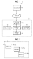
- FIG. 1 is a diagram illustrating the configuration of a service providing system 1.
- the service providing system 1 includes a client personal computer 4 of a user (hereinafter referred to as client PC 4) and a Web server 2 of an Internet service provider.
- the Web server 2 is a server that is used by the service provider to provide its service to the user.
- the client PC 4 and the Web server 2 can hold communication to/from each other over a network.
- the client PC 4 includes a control unit 6, a memory unit 8, an operation input unit 10, a display unit 12, and a network interface 14 (hereinafter referred to as network IF 14).
- the control unit 6 is a microprocessor and performs various types of information processing as programmed by programs that are stored in the memory unit 8.
- the memory unit 8 stores data that is needed by the control unit 6 in the process of information processing.
- the memory unit 8 also stores apluralityof applications including an operating system and a browser application (program) . These applications maybe read out of a computer-readable information storing medium such as a DVD (registered trademark)-ROM, or may be supplied from a communication network such as a network, to be stored in the memory unit 8.
- the operation input unit 10 is a mouse and a keyboard, or the like, and outputs an operation signal which indicates the specifics of operation made by the user to the control unit 6.
- the display unit 12 is, for example, a liquid crystal display, and displays information output from the control unit 6 on a screen.
- the network IF 14 is a communication interface for connecting the client PC 4 to the network.
- the user uses the browser application to display Web data distributed by the Web server 2 in a browser window as a Web page (object (document object)).
- Web data is data written in a markup language, here, HyperText Markup Language (HTML) data.
- HTML HyperText Markup Language
- the Web data which is distributed by the Web server 2 to be provided to the client PC 4 here may be read out of a computer-readable information storing medium such as a DVD (registered trademark)-ROM that is provided by the service provider.
- FIG. 2 is a diagram illustrating an example of what is displayed on the screen.
- the screen displays windows 16 of the respective applications. Specifically, a window 16a, a window 16b, and a window 16c are displayed. These windows 16 are allocated to applications by the operating system when the applications are activated, and are managed by the operating system.
- An xy coordinate system is set on the screen with the upper left vertex of the screen as the origin. An arbitrary position within the screen is expressed by coordinate values of the xy coordinate system.
- the window 16a, the window 16b, and the window 16c are hereinafter referred to as window A, window B, and window C, respectively.
- the window B (window) is a window of the browser application here.
- FIG. 3 is a diagram illustrating an example of a window management table, which is used by the operating system to manage windows.
- the window management table is stored in the memory unit 8.
- the window management table stores, for each window, coordinate values of an xy coordinate system that indicate the position of the upper left vertex of the window.
- the operating system updates the coordinate values.
- the window management table also stores, for each window, the size of the window, namely, the height and the width. An area occupied by a window on the screen is indicated by the position of the upper left vertex of the window and the size of the window.
- the window management table stores for each window a place in priority order as well.
- the operating system draws windows starting from windows that are low in the order of priority. Accordingly, when a part of one window overlaps with another window which is higher in priority order than the window in question, that part is covered with the other window.
- FIG. 4 illustrates another example of what is displayed on the screen in which the window B whose place in priority order is "2" overlaps with the window A whose place in priority order is "1".
- the operating system updates the place in priority order of this window to "1", and moves other windows that have been high in priority order relative to this window one step down in the order of priority as a rule.
- the window B which is a window of the browser application is described next.
- FIG. 5 is a diagram illustrating an example of the window B.
- the window B has a rectangular shape and includes a bar area 18 and a Web page display target area 20 (display target area).
- the bar area 18 is a rectangular-shaped area having as its vertices the upper left vertex of the window B, a point O 1 , a point O 4 , and the upper right vertex of the window B, and displays, for example, a title bar, a menu bar, and an address bar.
- the positions of the point O 1 and the point O 4 in the window B are set suitably in relation to the window size by the browser application.
- the Web page display target area 20 is an area contained in the window B as described above, in this embodiment, a rectangular-shaped area having as its vertices the point O 1 , the lower left vertex of the window B which is denoted by O 2 , the lower right vertex of the window B which is denoted by O 3 , and the point O 4 .
- An XY coordinate system having the point O 1 as the origin is set in the window B.
- An arbitrary position within the Web page display target area 20 is expressed by XY coordinate values of the XY coordinate system.
- a drawing target area 22 (drawing target area) is set in at least a part of the Web page display target area 20.
- the drawing target area 22 is a rectangular-shaped area having, as its upper left vertex, a reference point P which is at a position within the Web page display target area 20, and the point O 3 as its lower right vertex.
- a Web page containing a plurality of display elements is drawn in the drawing target area 22.
- the reference point P defines the drawing target area 22.
- a position where a Web page is drawn is therefore determined by the reference point P.
- the display elements are an image, text, a video, and the like, here a banner image which takes up a part of a Web page.
- the Web page here contains a display element A and a display element B.
- the service provider here recognizes the display element A as a display element that is the first in display priority order and recognizes the display element B as a display element that is the second in display priority order.
- the reference point P defines a margin between the Web page display target area 20 and the drawing target area 22. Specifically, an X-coordinate value "X 0 " of the reference point P defines the left margin width between the Web page display target area 20 and the drawing target area 22, and a Y-coordinate value "Y 0 " of the reference point P defines the upper margin width.
- the margin reference point P is set at the point O 1 in FIG. 5 . In short, X 0 and Y 0 are both "0". The Web page display target area 20 and the drawing target area 22 accordingly coincide with each other.
- the X-coordinate value "X 0 " of the reference point P may instead define the right margin width between the Web page display target area 20 and the drawing target area 22, and the Y-coordinate value "Y 0 " of the reference point P may instead define the lower margin width.
- the X-coordinate value "X 0 " of the reference point P defines the left margin width between the Web page display target area 20 and the drawing target area 22, and the Y-coordinate value "Y 0 " of the reference point P defines the upper margin width as described above.
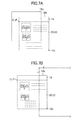
- FIG. 6 , FIG. 7A, and FIG. 7B are diagrams illustrating a transition of what is displayed on the screen.
- the window A whose place in priority order is "1" and the window B whose place in priority order is "2" are apart from each other (see FIG. 6 ) and the user moves the window A toward the window B, a part of the window B that is covered with the window A is no longer displayed on the screen and cannot be viewed.
- the display element A and the display element B are located in the part covered with the window A, the screen no longer displays the display element A and the display element B as illustrated in FIG. 7A .
- a part of the window B that is pushed out of the screen as a result of the user moving the window B is no longer displayed and visible as illustrated in FIG. 7B .
- the part pushed out of the screen is represented by a part indicated by the dotted line.
- the screen no longer displays the display element A and the display element B.
- the client PC 4 addresses this by taking an action described below when the display elements of the window B are not displayed on the screen for the reasons illustrated in FIGS. 7A and 7B .
- a part of the Web page display target area 20 that is covered with another window or a part of the Web page display target area 20 that is pushed out of the screen is referred to as non-visible area.
- non-visible area A part of the Web page display target area 20 that is covered with another window or a part of the Web page display target area 20 that is pushed out of the screen.
- the rest of the Web page display target area 20 which is a visible area remaining after excluding the non-visible area is referred to as actual display area.
- FIG. 7A the control unit 6 of the client PC 4 moves the reference point P so that the display element A which is higher in priority order than the display element B is displayed preferentially in the actual display area, without changing the layout of the Web page.
- FIG. 8 illustrates how the window B looks after the reference point P is moved downward (in the positive direction of the Y-axis).
- FIG. 9A illustrates how the window B looks after the reference point P is moved rightward (in the positive direction of the X-axis).
- the client PC 4 has more features. For instance, just displaying the display element A in the actual display area in the case of FIG. 7A is achieved by simply moving the reference point P rightward as illustrated in FIG. 10 . In the case of FIG. 10 , however, a hatched part (hereinafter referred to as blank area) generated by moving the reference point P is large and the Web page display target area 20 is not used efficiently.
- the client PC 4 addresses this by using the control unit 6 to move the reference point P in a manner that minimizes the planar dimensions of the blank area (the product of an increment in the X-coordinate of the reference point P and an increment in the Y-coordinate of the reference point P), which is generated by the moving of the reference point P.
- the client PC 4 has still more features. For instance, in the case of FIG. 11 where a large enough space to contain the whole display element A is not found anywhere in the actual display area, the display element A cannot be displayed in its entirety in the actual display area no matter where the reference point P is moved.
- the client PC 4 addresses this situation where the actual display area has no large enough space to contain the whole display element A by using the control unit 6 to move the reference point P so that one of display elements that are low in priority order relative to the display element A (here, the display element B which is one step lower) is displayed in the actual display area as illustrated in FIG. 12 .
- the control unit 6 moves the reference point P in a manner that minimizes the planar dimensions of the blank area.
- FIG. 13 is a diagram illustrating an example of what is written in HTML data that is the Web data. As illustrated in FIG. 13 , an ⁇ html> tag and a ⁇ /html> tag which indicate that the Web data is an HTML document are written in the Web data.
- a ⁇ body> tag and a ⁇ /body> tag are written as well.
- a script that is written by the service provider described above is written between the ⁇ body> tag and the ⁇ /body> tag.
- the script is a script section for determining the reference point P.
- Information about the respective display elements (sources, display sizes, placement in the Web page, etc.), the places in priority order of the respective display elements, an algorithm for determining the reference point P, and the like are written in the script.
- the browser application i.e., the control unit 6) sequentially executes parsing processing and rendering processing based on the reference point P determined by the script.
- the control unit 6 uses a given parsing algorithm to calculate, for each display element, X- and Y-coordinate values indicating the drawing area (position) of the display element based on the coordinate values (X 0 , Y 0 ) of the reference point P and information about the display element.
- the Web page is drawn in the drawing target area 22 based on the result of the parsing.
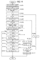
- FIG. 14 is a diagram exemplifying processing that is executed by the control unit 6, which operates as programmed by the browser application, by following the script in order to determine the reference point P.
- This processing is executed, when the client PC 4 receives the Web data, when the user operates one of the windows, when a given length of time elapses since the last execution of this processing, or the like.
- the control unit 6 first reads the priority order of display elements that is written in the script section (S101), and sorts a plurality of focus display elements among these display elements by the order of priority (S102).
- a focus display element corresponds to a focus part.
- Each display element contained in the Web page is treated as a focus display element here.
- display elements that are the first to the n-th (n is 3, for example) in priority order maybe selected as focus display elements.
- the value of E ini is set as the product of "X max ", which is the upper limit of "X 0 ", and "Y max ", which is the upper limit of "Y 0 ".
- the control unit 6 also sets the reference point P to the point O 1 (the initial position) (S105).
- the control unit 6 (obtaining means) then executes the parsing processing described above (S106). Calculated by the parsing processing for each display element are X- and Y-coordinate values that indicate the drawing area of the display element.
- the control unit 6 then identifies the actual display area (S107).
- the control unit 6 receives what is stored in the window management table from the operating system and, when a part of its own window is pushed out of the screen, calculates X- and Y-coordinate values indicating a part of the Web page display target area 20 that is not pushed out of the screen as X- and Y-coordinate values indicating the actual display area.
- the control unit 6 calculates, based on the x-coordinate value of this vertex, the X-coordinate value of the left edge of the part of the Web page display target area 20 that is not pushed out of the screen (i.e., the actual display area), and calculates X- and Y-coordinate values indicating the actual display area based on the obtained X-coordinate value.
- the control unit 6 identifies X- and Y-coordinate values that indicate the Web page display target area 20 as those of the actual display area.
- the control unit 6 calculates X- and Y-coordinate values indicating a part of its window that is not covered with the other window as X- and Y-coordinate values indicating the actual display area.
- the control unit 6 identifies the X- and Y-coordinate values of the lower right vertex of a part of the Web page display target area 20 that is covered with the other window based on the relation between the x- and y-coordinate values of the upper left vertex of its own window and the x- and y-coordinate values of the lower right vertex of the other window, and calculates X- and Y-coordinate values that indicate the actual display area based on the identified X- and Y-coordinate values.
- the control unit 6 determines whether or not the focus display element C i is displayed in the actual display area (S108) . In other words, the control unit 6 determines whether or not the drawing area of the focus display element C i is contained in the actual display area. When the drawing area of the focus display element C i is contained in the actual display area, it is determined that the focus display element C i is displayed in the actual display area. When the drawing area of the focus display element C i is not contained in the actual display area, it is determined that the focus display element C i is not displayed in the actual display area.
- the control unit 6 calculates the function value of a blank area evaluation function E (X 0 , Y 0 ) of "X 0 " and "Y 0 " for evaluating the planar dimensions of the blank area (see FIG. 8 and others).
- the function E(X 0 , Y 0 ) here is expressed as the product of "X 0 " and "Y 0 ".
- the value of E (X 0 , Y 0 ) is smaller when the blank area has smaller planar dimensions.
- the control unit 6 (setting means) then determines whether or not the function value of E (X 0 , Y 0 ) is less than the evaluation value E stored in the memory unit 8 (S110).
- the control unit 6 updates the evaluation value E with the function value of E (X 0 , Y 0 ) in order to minimize the planar dimensions of the blank area.
- the control unit 6 (setting means) also updates a candidate value "X m " and a candidate value "Y m " which are stored in the memory unit 8 with "X 0 " and "Y 0 ", respectively (S111).
- Step S108 In the case where it is determinedthat the focus displayelement C i is not displayed in the actual display area (No in S108), the focus display element C i is not displayed in the actual display area with the reference point P at the current position, and the control unit 6 therefore proceeds to Step S112. Even when it is determined in Step S108 that the focus display element C i is displayed in the actual display area, if the function value of E (X 0 , Y 0 ) exceeds the evaluation value E (Yes in S110) , the blank area does not have minimum planar dimensions with the reference point P at the current position, and the control unit 6 therefore proceeds to Step S112 as in the case where it is determined that the focus display element C i is not displayed in the actual display area.
- Steps S112 and S113 processing is executed in order to move the reference point P within the Web page display target area 20 along a travel path that follows the pattern of raster scanning. Specifically, the control unit 6 determines whether or not "X 0 " is equal to or more than "X max " (S112) and, when "X 0 " is not equal to or more than "X max " (No in S112), shifts the reference point P rightward by ⁇ X (S112a) .
- control unit 6 determines whether or not "Y 0 " is equal to or more than "Y max " (S113) in order to determine whether the reference point P has reached the end of the travel path.
- "Y 0 " is not equal to or more than "Y max " (No in S113)
- the control unit 6 therefore moves the reference point P to the left edge of the Web page display target area 20 while shifting the reference point P downward by ⁇ Y (S113a) .
- Appropriate positive real numbers can be set to ⁇ X and ⁇ Y.
- the evaluation value E being less than the initial value E ini means that a candidate for the reference point P with which the focus display element C i can be displayed in the actual display area is found along the travel path.
- the evaluation value E being equal to the initial value E ini means that such a candidate is not found along the travel path.
- control unit 6 sets "X 0 " to the candidate value "X m " and sets "Y 0 " to the candidate value "Y m “ (S115).
- the reference point P in this case is set to other positions than the point O 1 .
- the control unit 6 determines whether or not the focus display element C i is the last focus display element C N (S116) .
- the control unit 6 selects anew a focus display element that is next to the current focus display element C i as the new focus display element C i (S116a), and executes Step S104 and the subsequent steps again.
- the focus display element C i is the focus display element C N (Yes in S116)
- the reference point P is therefore set to the point O 1 (S117).
- control unit 6 draws the Web page in the drawing target area 22.
- the display element A can be displayed in the actual display area in the manners illustrated in FIG. 8 and FIG. 12 , for example.
- the display element A can be displayed in the actual display area without changing the size.
- the display element A can also be displayed in the actual display area while the planar dimensions of the blank area are minimized.
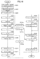
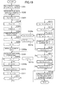
- control unit 6 may execute processing illustrated in FIG. 15 instead of the processing of FIG. 14 .
- the processing of FIG. 15 is described below.
- the processing of FIG. 14 is hereinafter referred to as a first processing mode and the processing of FIG. 15 is hereinafter referred to as a second processing mode.
- control unit 6 executes the same processing as Step S101 to obtain the priority order of display elements (S201) .
- the control unit 6 also executes the same processing as Step S102 to sort a plurality of focus display elements in ascending order of priority (S202).
- the control unit 6 selects one focus display element C i at a time the same way as in the first processing mode, and moves the reference point P from the point O 1 along the travel path described above to search for the position of the reference point P with which the focus display element C i can be displayed in the actual display area.
- the processing in the second processing mode is ended at the time when it is determined that the focus display element C i is displayed in the actual display area, without calculating the function value of the blank area evaluation function E (X 0 , Y 0 ).
- the control unit 6 then executes the same processing as Step S105 and sets the reference point P to the point O 1 (S204) without performing the same processing as S104.
- the control unit 6 then executes the parsing processing (S205), the identifying of the actual display area (S206), and the determining of whether or not the focus display element C i is displayed in the actual display area (S207) as in the first processing mode.
- control unit 6 executes processing for moving the reference point P along the travel path (S208, S208a, S209, and S209a) as in the first processing mode.
- control unit 6 ends the processing at that point without performing the same processing as Steps S109 to S111.
- the control unit 6 determines whether or not the focus display element C i is the last focus display element C N (S210). When the focus display element C i is not the last focus display element C N (No in S210), the control unit 6 selects anew a focus display element that is next to the current focus display element C i as the new focus display element C i (S210a), and executes Step S204 and the subsequent steps again.
- the control unit 6 sets the reference point P to the point O 1 (S211).
- the control unit 6 sets the reference point P by focusing only on the selected focus display element. The control unit 6 thus ensures that the selected focus display element is displayed in the actual display area. In the first processing mode and the second processing mode, attention is paid only to the selected focus display element and the presence of other focus display elements than the selected focus display element is not taken into consideration.
- control unit 6 may execute processing illustrated in FIG. 16 (third processing mode) instead of the processing of FIG. 14 .
- the third processing mode is described below.
- control unit 6 executes the same processing as Step S101 to obtain the priority order of display elements (S301).
- the control unit 6 then executes the same processing as Step S102 to sort the plurality of focus display elements in ascending order of priority (S302) and set the reference point P to the point O 1 (S303) .
- the control unit 6 then executes Steps S304 to S317a to evaluate each position along the travel path described above mainly from the viewpoint of how many focus display elements are displayed in the actual display area.
- the control unit 6 also identifies a position that has earned the highest evaluation by executing Steps S314 and S315, in particular.
- control unit 6 initializes a maximum evaluation value E max with an initial value "0" (S304), and executes parsing processing (S305).
- the control unit 6 then executes the same processing as Step S107 to identify the actual display area (S306), and selects the focus display element C i that is the highest in priority order (namely, C 1 ) (S307) .
- the control unit 6 also initializes an evaluation value E 1 with the initial value "0" (S308).
- the control unit 6 executes Steps S309 to S312a to calculate, for each focus display element C i , an individual evaluation value E i (r i ), and calculates the evaluation value E 1 mentioned above, which is the sum of these individual evaluation values.
- control unit 6 calculates a displayed proportion r i of the focus display element C i (S309).
- the displayed proportion r i here is the proportion of the planar dimensions of a part of a drawing area for the focus display element C i that is contained in the actual display area to the planar dimensions of this drawing area.
- the control unit 6 then calculates the individual evaluation value E i (r i ) (S310).
- the individual evaluation value E i (r i ) here is the function value of the place in priority order "i" of the focus display element C i and the displayed proportion r i of the focus display element C i .
- E i (r i ) N + 1 - i / N ⁇ r j
- the individual evaluation value E i (r i ) is a decreasing function of the place in priority order "i".
- the evaluation value E 1 is accordingly a decreasing function of the place in priority order "i" as well.
- the individual evaluation value E i (r i ) is an increasing function of the displayed proportion r i of the focus display element C i .
- the evaluation value E 1 is accordingly an increasing function of the displayed proportion r i of the focus display element C i as well.
- the control unit 6 After calculating the individual evaluation value E i (r i ), the control unit 6 adds the calculated individual evaluation value E i (r i ) to the evaluation value E 1 (S311).
- the control unit 6 selects a focus display element that is one step below the focus display element C i in priority order (S312a), and returns to Step S309.
- the control unit 6 calculates a position evaluation value E 2 , which indicates an evaluation of the current position (S313). A larger value of the position evaluation value E 2 indicates a higher evaluation. Specifically, the control unit 6 calculates the function value of a blank area evaluation function E(X 0 , Y 0 ) that differs from the one in the first processing mode, and calculates the product of the function value of the blank area evaluation function E(X 0 , Y 0 ) and the evaluation value E 1 as the position evaluation value E 2 .
- the value of "X 0 ⁇ Y 0 " is smaller when the blank area has smaller planar dimensions as described above.
- the function value of the blank area evaluation function E(X 0 , Y 0 ) is therefore larger when the blank area has smaller planar dimensions.
- the position evaluation value E 2 which is an increasing function of the function value of the blank area evaluation function E(X 0 , Y 0 ), accordingly yields a higher evaluation when the blank area has smaller planar dimensions.
- the evaluation value E 1 is an increasing function of the displayed proportion r i of the focus display element C i as described above.
- the position evaluation value E 2 is therefore an increasing function of the displayed proportion r i of the focus display element C i as well. Accordingly, the position evaluation value E 2 indicates a higher evaluation when more focus display elements are displayed in the actual display area.
- the evaluation value E 1 is a decreasing function of the place in priority order "i"
- the position evaluation value E 2 is therefore a decreasing function of the place in order of priority "i” as well.
- the position evaluation value E 2 of a focus display element that is displayed in the actual display area is accordingly higher when the focus display element is higher in priority order.
- the control unit 6 (setting means) then determines whether or not the position evaluation value E 2 is larger than the maximum evaluation value E max (S314). When the position evaluation value E 2 is equal to or less than the maximum evaluation value E max (No in S314), the control unit 6 proceeds to Step S316 in order to move the reference point. In the case where the position evaluation value E 2 is larger than the maximum evaluation value E max (Yes in S314), on the other hand, the control unit 6 updates the maximum evaluation value E max with the position evaluation value E 2 , and sets the candidate value "X m " and the candidate value "Y m “ to "X 0 " and "Y 0 ", respectively (S315), and then proceeds to Step S316.
- Steps S316 to S317a processing for moving the reference point P is performed. Specifically, the control unit 6 determines whether or not "X 0 " is equal to or more than the "X max " (S316), and shifts the reference point P rightward by ⁇ X when "X 0 " is not equal to or more than "X max " (No in S316) . In the case where "X 0 " is equal to or more than "X max " (Yes in S316), on the other hand, the control unit 6 determines whether or not "Y 0 " is equal to or more than "Y max " (S317) in order to determine whether or not the reference point P has reached the end of the travel path.
- control unit 6 sets a position (X m , Y m ) as the reference point P in order to set a position that has earned the highest evaluation as the reference point P (S318).
- a higher evaluation is given when more focus display elements are displayed in the actual display area as described above. Therefore, as many focus display elements as possible can be displayed in the actual display area according to the third processing mode. In addition, a higher evaluation is given when a focus display element displayed in the actual display area is higher in priority order as described above.
- the third processing mode therefore makes it possible to preferentially display focus display elements that are high in priority order in the actual display area.
- the third processing mode can also reduce the blank area because a higher evaluation is given when the blank area has smaller planar dimensions as described above.
- the display element A can be displayed in the actual display area in the manners illustrated in FIG. 8 and FIG. 12 as in the first processing mode.
- the definitional expressions of the individual evaluation value E i ( ri ) and the blank area evaluation function E(X 0 , Y 0 ) are set accordingly.
- the "window” in the embodiment described above is not limited to the window B of the browser application, and can be a window of any type of application.
- a window of a document application for example, may correspond to the "window”.
- control unit 6 may assign a lower place in priority order to a focus display element that is displayed in the actual display area when the reference point P is set, in the case where the reference point P is set to other positions than the point O 1 .
- This enables the information processing device to avoid keeping displaying only a particular focus part (for example, a focus display element that is high in priority order) preferentially in the actual display area.
- This is accomplished in the first processing mode by the control unit 6 by executing the following processing after Step S115. Specifically, after Step S115, the control unit 6 lowers the focus display element C i in priority order as illustrated in FIG. 17 (S115a).
- the control unit 6 executes the following processing when it is determined that the focus display element C i is displayed (Yes in S207). Specifically, the control unit 6 determines whether or not the reference point P is the point O 1 (S207a) and, when the reference point P is not the point O 1 (No in S207a), lowers the focus display element C i in priority order (S207b) as illustrated in FIG. 18 .
- the control unit 6 additionally performs the following processing. Specifically, the control unit 6 initializes an element set S with an empty set (S308a) after Step S308 as illustrated in FIG. 19 . After calculating the displayed proportion r i in Step S309, the control unit 6 determines whether or not the displayed proportion r i is equal to ormore than the reference proportion r s (S309a). When the displayed proportion r i is equal to or more than the reference proportion r s (Yes in S309a), the control unit 6 adds the focus display element C i to the element set S (S309b) .
- the control unit 6 sets the element set S as a candidate set So (S315a) in addition to executing Step S315.
- the control unit 6 sets the reference point P in Step S318, and determines whether or not the set reference point P is the point O 1 (S318a).
- the control unit 6 assigns a lower place in priority order to a focus display element that belongs to the candidate set So (S318b) .
Abstract
Description
- The present invention relates to an information processing device, a method of controlling an information processing device, a program, and an information recording medium.
- Display elements disposed in a part of a display target area set within a window that is not displayed on the screen and therefore is not visible cannot be viewed on the screen. The following patent literature deals with this and describes, when a part of a display target area is not visible, displaying a cursor position of text disposed in the part of the display target area that is not visible in a visible part of the window by scrolling processing while shrinking the display target area (see
FIG. 13 ofPatent Literature 1, for example). - [Patent Literature 1]
JP 10-11263 A - In the patent literature, the cursor position is moved by scrolling in a given direction irrespective of the shape of an actually displayed part, which is a part of the display target area that is visible on the screen. a position where the text that was in the non-visible part is displayed in the actually displayed part is practically limited for that reason. Therefore, in the case of displaying a display element that was disposed in a non-visible part, for example, an image or a table, in the actually displayed part, the display element cannot be displayed in the actually displayedpart if there is no sufficient space at the display position in the actual display area, unless the size of the display element is changed (e.g., reduced).
- In addition, the technology of the patent literature reduces the size of the display target area in a given direction when the display target area becomes partially hidden from view. The layout of the display element consequently falls apart depending on the direction in which the text is written.
- An object of the present invention is to display a focus part of a display object in an actual display area, which is a part of a display target area set within a window that is visible on the screen, without changing the size of the focus part and the layout of the display object.
- In order to solve the above-mentioned problems, an information processing device according to the present invention includes: obtaining means for obtaining a position in a display target area, which is within a window, of a focus part of an object that is drawn in the display target area or that is to be drawn in the display target area; identifying means for identifying an actual display area, which is a part of the display target area that is visible on a screen; and setting means for setting a position where the object is drawn so that the focus part is displayed in the actual display area, based on the obtained position of the focus part and the identified actual display area. Examples of the object include a document object (e.g., a Web page) and an image object (e.g., an electronic map) . The focus part is, for example, an item among contents (e.g., text, a link, and an image) disposed within a document object, or an at least partial area of the document object, or a point within an image object or an at least partial area of an image object. The object can be drawn in a drawing target area, which is, for example, at least a part of the display target area and which is defined by a reference point within the display target area. The setting means in this case sets the reference point based on the position of the focus part and the identified actual display area.
- Further, in order to solve the above-mentioned problems, a method of controlling an information processing device according to the present invention includes: an obtaining step of obtaining a position in a display target area, which is within a window, of a focus part of an object that is drawn in the display target area or that is to be drawn in the display target area; an identifying step of identifying an actual display area, which is a part of the display target area that is visible on a screen; and a setting step of setting a position where the object is drawn so that the focus part is displayed in the actual display area, based on the obtained position of the focus part and the identified actual display area.
- Further, in order to solve the above-mentioned problems, a program according to the present invention causes a computer to function as: obtaining means for obtaining a position in a display target area, which is within a window, of a focus part of an object that is drawn in the display target area or that is to be drawn in the display target area; identifying means for identifying an actual display area, which is a part of the display target area that is visible on a screen; and setting means for setting a position where the object is drawn so that the focus part is displayed in the actual display area, based on the obtained position of the focus part and the identified actual display area.
- Further, the computer-readable information recording medium of the present invention is a computer-readable information recording medium having the above-mentioned program recorded thereon.
- According to the present invention, where the object is drawn is set based on the position of a focus part and the actual display area, and the focus part of the object can therefore be displayed in the actual display area without changing the size of the focus part and the layout of the object.
- In an aspect of the present invention, a position where the object is drawn may be set "when it is determined that a position of the focus part is not contained in the actual display area due to the position of the window in the screen". In other words, a position where the obj ect is drawn may not be set "when it is determined that a position of the focus part is not contained in the actual display area for other reasons than the position of the window". "When it is determined that a position of the focus part is not contained in the actual display area due to the position of the window in the screen" is, for example, "when it is determined that, because another window is partially overlaid on the window in question, a position of the focus part is not contained in a part of the display target area where the other window is not overlaid (i.e., the actual display area)" or "when it is determined that, because a part of the window is not within the screen, the position of the focus part is not contained in a part of the display target area that is within the screen (i.e., the actual display area) ". "When it is determined that the position of the focus part is not contained in the actual display area for other reasons than the position of the window" is, for example, "when it is determined that the position of the focus part is not contained in the display target area (i.e., the actual display area) as a result of scrolling". This way, a position where the obj ect is drawn is not set when, for example, it is determined that the position of the focus part is not contained in the actual display area as a result of scrolling, and the focus part of the object can therefore be displayed in the actual display area while avoiding irritating the user.
- According to an aspect of the present invention, the obtaining means may obtain, for each of a plurality of positions within the display target area, a position where the focus part is positioned in the display target area in a case where each of the plurality of positions is set as the reference point, the information processing device may further include exposure amount evaluating means for evaluating, for each of the plurality of positions, an amount of exposure of the focus part in the actual display area in a case where each of the plurality of positions is set as the reference point, based on the position obtained by the obtaining means for each of the plurality of positions, and the setting means may set the reference point based on an evaluation result obtained by the exposure amount evaluating means for each of the plurality of positions. This way, the amount of exposure of the focus part in the actual display area can be taken into account when setting the reference point. For instance, this enables the information processing device to set the reference point according to which a given proportion of the focus part is displayed.
- Further, according to an aspect of the present invention, the information processing device may further include blank area evaluating means for evaluating, for each of the plurality of positions, an amount of a blank area that is generated in a case where each of the plurality of positions is set as the reference point, based on each of the plurality of positions, and the setting means may set the reference point based on evaluation results obtained by the exposure amount evaluating means and the blank area evaluating means for each of the plurality of positions. This way, the blank area that is generated by setting the reference point can be taken into account when setting the reference point. For instance, this enables the information processing device to set the reference point that minimizes the blank area.
- Further, according to an aspect of the present invention, the object may include a plurality of the focus parts, the obtaining means may obtain, for each of the plurality of positions, positions where each focus part is positioned in the display target area in a case where each of the plurality of positions is set as the reference point, the exposure amount evaluating means may evaluate, for each of the plurality of positions, the amount of exposure of each of focus part in a case where each of the plurality of positions is set as the reference point, and the setting means may set the reference point based on the evaluation result of the exposure amount of each focus part obtained for each of the plurality of positions. This way, the amount of exposure of the focus part in the actual display area can be taken into account when setting the reference point. For instance, this enables the information processing device to set the reference point with which as many focus display elements as possible can be displayed in the actual display area.
- Further, according to an aspect of the present invention, a place in priority order may be set to each focus part, and the setting means may set the reference point based on the evaluation result of the exposure amount of each focus part obtained for each of the plurality of positions, and on the place in priority order of each focus part. This way, the order of priority of each focus parts can be taken into account when setting the reference point. For instance, this enables the information processing device to preferentially display focus parts that are high in priority order.
- Further, according to an aspect of the present invention, the object may include a plurality of the focus parts, to each of which a place in priority order is set, the information processing device may further include selecting means for selecting one of the plurality of the focus parts based on the priority order, the obtaining means may obtain, for each of the plurality of positions, a position where the selected one of the plurality of the focus parts is positioned in the display target area in a case where each of the plurality of positions is set as the reference point, and the exposure amount evaluating means may evaluate, for each of the plurality of positions, an amount of exposure of the selected one of the plurality of the focus parts in a case where each of the plurality of positions is set as the reference point, based on the position obtained by the obtaining means for the each of the plurality of positions. In this way, too, the order of priority of the focus parts can be taken into account when setting the reference point. For instance, this enables the information processing device to preferentially display focus parts that are high in priority order.
- Further, according to an aspect of the present invention, when an evaluation result obtained for each of the plurality of positions satisfies a given condition, the selecting means may restrict the setting of the reference point, which is performed by the setting means based on the evaluation result, and select another focus point anew based on the priority order. This way, which one of the focus parts is to be paid attention to can be switched in an order based on the order of priority when, for example, the reference point is set.
- Further, according to an aspect of the present invention, the information processing device may assign a lower place in the priority order to the focus part that is displayed in the display target area when the setting means sets the reference point, in a case where the setting means sets the reference point to other positions than an initial position of the reference point. This enables the information processing device to, for example, avoid keeping displaying only a particular focus part in the actual display area.
-
-
FIG. 1 is a diagram illustrating the configuration of a service providing system. -
FIG. 2 is a diagram illustrating an example of contents displayed on a screen. -
FIG. 3 is a diagram illustrating an example of a window management table. -
FIG. 4 is a diagram illustrating another example of what is displayed on the screen. -
FIG. 5 is a diagram illustrating an example of a window B. -
FIG. 6 is a diagram illustrating a transition of what is displayed on the screen. -
FIG. 7A is a diagram illustrating a transition of what is displayed on the screen. -
FIG. 7B is a diagram illustrating a transition of what is displayed on the screen. -
FIG. 8 is a diagram illustrating the window B. -
FIG. 9A is a diagram illustrating the window B. -
FIG. 9B is a diagram illustrating the window B. -
FIG. 10 is a diagram illustrating the window B. -
FIG. 11 is a diagram illustrating the window B. -
FIG. 12 is a diagram illustrating the window B. -
FIG. 13 is a diagram illustrating an example of what is written in Web data. -
FIG. 14 is a flow chart illustrating an example of processing executed by a control unit. -
FIG. 15 is a flow chart illustrating another example of the processing executed by the control unit. -
FIG. 16 is a flow chart illustrating still another example of the processing executed by the control unit. -
FIG. 17 is a flow chart illustrating still another example of the processing executed by the control unit. -
FIG. 18 is a flow chart illustrating still another example of the processing executed by the control unit. -
FIG. 19 is a flow chart illustrating still another example of the processing executed by the control unit. - An exemplary embodiment of the present invention is described below with reference to the drawings.
-
FIG. 1 is a diagram illustrating the configuration of aservice providing system 1. As illustrated inFIG. 1 , theservice providing system 1 includes a clientpersonal computer 4 of a user (hereinafter referred to as client PC 4) and aWeb server 2 of an Internet service provider. TheWeb server 2 is a server that is used by the service provider to provide its service to the user. Theclient PC 4 and theWeb server 2 can hold communication to/from each other over a network. - The
client PC 4 includes acontrol unit 6, amemory unit 8, anoperation input unit 10, adisplay unit 12, and a network interface 14 (hereinafter referred to as network IF 14). - The
control unit 6 is a microprocessor and performs various types of information processing as programmed by programs that are stored in thememory unit 8. Thememory unit 8 stores data that is needed by thecontrol unit 6 in the process of information processing. Thememory unit 8 also stores apluralityof applications including an operating system and a browser application (program) . These applications maybe read out of a computer-readable information storing medium such as a DVD (registered trademark)-ROM, or may be supplied from a communication network such as a network, to be stored in thememory unit 8. - The
operation input unit 10 is a mouse and a keyboard, or the like, and outputs an operation signal which indicates the specifics of operation made by the user to thecontrol unit 6. Thedisplay unit 12 is, for example, a liquid crystal display, and displays information output from thecontrol unit 6 on a screen. The network IF 14 is a communication interface for connecting theclient PC 4 to the network. - The user uses the browser application to display Web data distributed by the
Web server 2 in a browser window as a Web page (object (document object)). The Web data is data written in a markup language, here, HyperText Markup Language (HTML) data. The Web data which is distributed by theWeb server 2 to be provided to theclient PC 4 here may be read out of a computer-readable information storing medium such as a DVD (registered trademark)-ROM that is provided by the service provider. -
FIG. 2 is a diagram illustrating an example of what is displayed on the screen. As illustrated inFIG. 2 , the screen displays windows 16 of the respective applications. Specifically, awindow 16a, awindow 16b, and a window 16c are displayed. These windows 16 are allocated to applications by the operating system when the applications are activated, and are managed by the operating system. An xy coordinate system is set on the screen with the upper left vertex of the screen as the origin. An arbitrary position within the screen is expressed by coordinate values of the xy coordinate system. - The
window 16a, thewindow 16b, and the window 16c are hereinafter referred to as window A, window B, and window C, respectively. The window B (window) is a window of the browser application here. -
FIG. 3 is a diagram illustrating an example of a window management table, which is used by the operating system to manage windows. The window management table is stored in thememory unit 8. As illustrated inFIG. 3 , the window management table stores, for each window, coordinate values of an xy coordinate system that indicate the position of the upper left vertex of the window. When the user moves a window, the operating system updates the coordinate values. The window management table also stores, for each window, the size of the window, namely, the height and the width. An area occupied by a window on the screen is indicated by the position of the upper left vertex of the window and the size of the window. - The window management table stores for each window a place in priority order as well. The operating system draws windows starting from windows that are low in the order of priority. Accordingly, when a part of one window overlaps with another window which is higher in priority order than the window in question, that part is covered with the other window.
FIG. 4 illustrates another example of what is displayed on the screen in which the window B whose place in priority order is "2" overlaps with the window A whose place in priority order is "1". - When the user operates one of the windows, the operating system updates the place in priority order of this window to "1", and moves other windows that have been high in priority order relative to this window one step down in the order of priority as a rule.
- The window B which is a window of the browser application is described next.
-
FIG. 5 is a diagram illustrating an example of the window B. As illustrated inFIG. 5 , the window B has a rectangular shape and includes abar area 18 and a Web page display target area 20 (display target area). - The
bar area 18 is a rectangular-shaped area having as its vertices the upper left vertex of the window B, a point O1, a point O4, and the upper right vertex of the window B, and displays, for example, a title bar, a menu bar, and an address bar. The positions of the point O1 and the point O4 in the window B are set suitably in relation to the window size by the browser application. - The Web page
display target area 20 is an area contained in the window B as described above, in this embodiment, a rectangular-shaped area having as its vertices the point O1, the lower left vertex of the window B which is denoted by O2, the lower right vertex of the window B which is denoted by O3, and the point O4. An XY coordinate system having the point O1 as the origin is set in the window B. An arbitrary position within the Web pagedisplay target area 20 is expressed by XY coordinate values of the XY coordinate system. - A drawing target area 22 (drawing target area) is set in at least a part of the Web page
display target area 20. The drawingtarget area 22 is a rectangular-shaped area having, as its upper left vertex, a reference point P which is at a position within the Web pagedisplay target area 20, and the point O3 as its lower right vertex. A Web page containing a plurality of display elements is drawn in thedrawing target area 22. The reference point P defines the drawingtarget area 22. A position where a Web page is drawn is therefore determined by the reference point P. The display elements are an image, text, a video, and the like, here a banner image which takes up a part of a Web page. The Web page here contains a display element A and a display element B. The service provider here recognizes the display element A as a display element that is the first in display priority order and recognizes the display element B as a display element that is the second in display priority order. - The reference point P defines a margin between the Web page
display target area 20 and thedrawing target area 22. Specifically, an X-coordinate value "X0" of the reference point P defines the left margin width between the Web pagedisplay target area 20 and thedrawing target area 22, and a Y-coordinate value "Y0" of the reference point P defines the upper margin width. The margin reference point P is set at the point O1 inFIG. 5 . In short, X0 and Y0 are both "0". The Web pagedisplay target area 20 and thedrawing target area 22 accordingly coincide with each other. The X-coordinate value "X0" of the reference point P may instead define the right margin width between the Web pagedisplay target area 20 and thedrawing target area 22, and the Y-coordinate value "Y0" of the reference point P may instead define the lower margin width. Here, the X-coordinate value "X0" of the reference point P defines the left margin width between the Web pagedisplay target area 20 and thedrawing target area 22, and the Y-coordinate value "Y0" of the reference point P defines the upper margin width as described above. -
FIG. 6 ,FIG. 7A, and FIG. 7B are diagrams illustrating a transition of what is displayed on the screen. In theservice providing system 1 described above, when the window A whose place in priority order is "1" and the window B whose place in priority order is "2" are apart from each other (seeFIG. 6 ) and the user moves the window A toward the window B, a part of the window B that is covered with the window A is no longer displayed on the screen and cannot be viewed. In this case, if the display element A and the display element B are located in the part covered with the window A, the screen no longer displays the display element A and the display element B as illustrated inFIG. 7A . - To give another example, a part of the window B that is pushed out of the screen as a result of the user moving the window B is no longer displayed and visible as illustrated in
FIG. 7B . The part pushed out of the screen is represented by a part indicated by the dotted line. In this case, if the display element A and the display element B are located in the part pushed out of the screen, the screen no longer displays the display element A and the display element B. - The
client PC 4 addresses this by taking an action described below when the display elements of the window B are not displayed on the screen for the reasons illustrated inFIGS. 7A and 7B . - The following description is about this point. A part of the Web page
display target area 20 that is covered with another window or a part of the Web pagedisplay target area 20 that is pushed out of the screen is referred to as non-visible area. In the case ofFIG. 7A , a rectangular-shaped area having the point O1 as its upper left vertex and the lower right vertex of the window A as its lower right vertex qualifies as a non-visible area. The rest of the Web pagedisplay target area 20 which is a visible area remaining after excluding the non-visible area is referred to as actual display area. - In the case of
FIG. 7A , thecontrol unit 6 of theclient PC 4 moves the reference point P so that the display element A which is higher in priority order than the display element B is displayed preferentially in the actual display area, without changing the layout of the Web page.FIG. 8 illustrates how the window B looks after the reference point P is moved downward (in the positive direction of the Y-axis). - Features of the
client PC 4 are not limited to this. For instance, just displaying the display element A in the actual display area is achieved by simply moving the reference point P all the time as inFIG. 8 . In the case ofFIG. 9A , however, moving the reference point P downward does not help because there is no large enough space to contain the whole display element A due to the relation between the size and shape of the actual display area and the size and shape of the display element A, and the display element A in its current size cannot be displayed in the actual display area. Theclient PC 4 addresses this by moving the reference point P so that the display element A can be displayed in its current size in the actual display area.FIG. 9B illustrates how the window B looks after the reference point P is moved rightward (in the positive direction of the X-axis). - The
client PC 4 has more features. For instance, just displaying the display element A in the actual display area in the case ofFIG. 7A is achieved by simply moving the reference point P rightward as illustrated inFIG. 10 . In the case ofFIG. 10 , however, a hatched part (hereinafter referred to as blank area) generated by moving the reference point P is large and the Web pagedisplay target area 20 is not used efficiently. Theclient PC 4 addresses this by using thecontrol unit 6 to move the reference point P in a manner that minimizes the planar dimensions of the blank area (the product of an increment in the X-coordinate of the reference point P and an increment in the Y-coordinate of the reference point P), which is generated by the moving of the reference point P. - The
client PC 4 has still more features. For instance, in the case ofFIG. 11 where a large enough space to contain the whole display element A is not found anywhere in the actual display area, the display element A cannot be displayed in its entirety in the actual display area no matter where the reference point P is moved. - The
client PC 4 addresses this situation where the actual display area has no large enough space to contain the whole display element A by using thecontrol unit 6 to move the reference point P so that one of display elements that are low in priority order relative to the display element A (here, the display element B which is one step lower) is displayed in the actual display area as illustrated inFIG. 12 . In this case, too, thecontrol unit 6 moves the reference point P in a manner that minimizes the planar dimensions of the blank area. - The description given below is about processing executed in the
client PC 4. Web data for drawing a Web page in thedrawing target area 22 is described first. -
FIG. 13 is a diagram illustrating an example of what is written in HTML data that is the Web data. As illustrated inFIG. 13 , an <html> tag and a </html> tag which indicate that the Web data is an HTML document are written in the Web data. - A <body> tag and a </body> tag are written as well. A script that is written by the service provider described above is written between the <body> tag and the </body> tag. The script is a script section for determining the reference point P. Information about the respective display elements (sources, display sizes, placement in the Web page, etc.), the places in priority order of the respective display elements, an algorithm for determining the reference point P, and the like are written in the script. The browser application (i.e., the control unit 6) sequentially executes parsing processing and rendering processing based on the reference point P determined by the script. In the parsing processing, the
control unit 6 uses a given parsing algorithm to calculate, for each display element, X- and Y-coordinate values indicating the drawing area (position) of the display element based on the coordinate values (X0, Y0) of the reference point P and information about the display element. In the rendering processing, the Web page is drawn in thedrawing target area 22 based on the result of the parsing. -
FIG. 14 is a diagram exemplifying processing that is executed by thecontrol unit 6, which operates as programmed by the browser application, by following the script in order to determine the reference point P. This processing is executed, when theclient PC 4 receives the Web data, when the user operates one of the windows, when a given length of time elapses since the last execution of this processing, or the like. - The
control unit 6 first reads the priority order of display elements that is written in the script section (S101), and sorts a plurality of focus display elements among these display elements by the order of priority (S102). A focus display element corresponds to a focus part. Each display element contained in the Web page is treated as a focus display element here. Alternatively, display elements that are the first to the n-th (n is 3, for example) in priority order maybe selected as focus display elements. Each focus display element is hereinafter denoted by Ci (i=1 to N) . A smaller value of "i" indicates a higher place in priority order. - The control unit 6 (selecting means) selects the focus display element Ci that is the highest in priority order (i=1) (S103), and sets an initial value Eini to an evaluation value E, which is stored in the memory unit 8 (S104). The value of Eini is set as the product of "Xmax", which is the upper limit of "X0", and "Ymax", which is the upper limit of "Y0". The
control unit 6 also sets the reference point P to the point O1 (the initial position) (S105). - The control unit 6 (obtaining means) then executes the parsing processing described above (S106). Calculated by the parsing processing for each display element are X- and Y-coordinate values that indicate the drawing area of the display element.
- The
control unit 6 then identifies the actual display area (S107). In the case of the processing procedure ofFIG. 14 , thecontrol unit 6 receives what is stored in the window management table from the operating system and, when a part of its own window is pushed out of the screen, calculates X- and Y-coordinate values indicating a part of the Web pagedisplay target area 20 that is not pushed out of the screen as X- and Y-coordinate values indicating the actual display area. For example, when the left edge of its own window is pushed out of the screen, in other words, when the x-coordinate value of the upper left vertex of its own window is less than "0", thecontrol unit 6 calculates, based on the x-coordinate value of this vertex, the X-coordinate value of the left edge of the part of the Web pagedisplay target area 20 that is not pushed out of the screen (i.e., the actual display area), and calculates X- and Y-coordinate values indicating the actual display area based on the obtained X-coordinate value. - In the case where the left edge of its own window is not pushed out of the screen, when there are no windows that are higher in priority order than its own window, or there is a window that is higher in priority order than its own window but all of the vertices of its own window are not within the other window, the
control unit 6 identifies X- and Y-coordinate values that indicate the Web pagedisplay target area 20 as those of the actual display area. On the other hand, when one of the vertices of its own window is within the other window, for example, thecontrol unit 6 calculates X- and Y-coordinate values indicating a part of its window that is not covered with the other window as X- and Y-coordinate values indicating the actual display area. Specifically, when the upper left vertex, for example, of its own window is within the other window, thecontrol unit 6 identifies the X- and Y-coordinate values of the lower right vertex of a part of the Web pagedisplay target area 20 that is covered with the other window based on the relation between the x- and y-coordinate values of the upper left vertex of its own window and the x- and y-coordinate values of the lower right vertex of the other window, and calculates X- and Y-coordinate values that indicate the actual display area based on the identified X- and Y-coordinate values. - The control unit 6 (exposure amount evaluating means) then determines whether or not the focus display element Ci is displayed in the actual display area (S108) . In other words, the
control unit 6 determines whether or not the drawing area of the focus display element Ci is contained in the actual display area. When the drawing area of the focus display element Ci is contained in the actual display area, it is determined that the focus display element Ci is displayed in the actual display area. When the drawing area of the focus display element Ci is not contained in the actual display area, it is determined that the focus display element Ci is not displayed in the actual display area. - "When the focus display element Ci is displayed in the actual display area" may be defined as "when a given proportion rs or more of the drawing area of the focus display element Ci is contained in the actual display area". "When the focus display element Ci is not displayed in the actual display area" may be defined as "when less than the given proportion rs of the drawing area of the focus display element Ci is contained in the actual display area".
- In the case where the focus display element Ci is displayed in the actual display area (Yes in S108) and the reference point P is not at the initial position (namely, the point O1) (No in S109), the control unit 6 (blank area evaluating means) calculates the function value of a blank area evaluation function E (X0, Y0) of "X0" and "Y0" for evaluating the planar dimensions of the blank area (see
FIG. 8 and others). The function E(X0, Y0) here is expressed as the product of "X0" and "Y0". The value of E (X0, Y0) is smaller when the blank area has smaller planar dimensions. The control unit 6 (setting means) then determines whether or not the function value of E (X0, Y0) is less than the evaluation value E stored in the memory unit 8 (S110). - When the function value of E (X0, Y0) is less than the evaluation value E (Yes in S110), the control unit 6 (setting means) updates the evaluation value E with the function value of E (X0, Y0) in order to minimize the planar dimensions of the blank area. The control unit 6 (setting means) also updates a candidate value "Xm" and a candidate value "Ym" which are stored in the
memory unit 8 with "X0" and "Y0", respectively (S111). - In the case where it is determinedthat the focus displayelement Ci is not displayed in the actual display area (No in S108), the focus display element Ci is not displayed in the actual display area with the reference point P at the current position, and the
control unit 6 therefore proceeds to Step S112. Even when it is determined in Step S108 that the focus display element Ci is displayed in the actual display area, if the function value of E (X0, Y0) exceeds the evaluation value E (Yes in S110) , the blank area does not have minimum planar dimensions with the reference point P at the current position, and thecontrol unit 6 therefore proceeds to Step S112 as in the case where it is determined that the focus display element Ci is not displayed in the actual display area. - In Steps S112 and S113, processing is executed in order to move the reference point P within the Web page
display target area 20 along a travel path that follows the pattern of raster scanning. Specifically, thecontrol unit 6 determines whether or not "X0" is equal to or more than "Xmax" (S112) and, when "X0" is not equal to or more than "Xmax" (No in S112), shifts the reference point P rightward by ΔX (S112a) . In the case where "X0" is equal to or more than "Xmax" (Yes in S112), on the other hand, thecontrol unit 6 determines whether or not "Y0" is equal to or more than "Ymax" (S113) in order to determine whether the reference point P has reached the end of the travel path. When "Y0" is not equal to or more than "Ymax" (No in S113), it means that the reference point P has not reached the end of the travel path yet. Thecontrol unit 6 therefore moves the reference point P to the left edge of the Web pagedisplay target area 20 while shifting the reference point P downward by ΔY (S113a) . Appropriate positive real numbers can be set to ΔX and ΔY. - In the case where "Y0" is equal to or more than "Ymax" (Yes in S113), on the other hand, it means that the reference point P has reached the end of the travel path. The control unit 6 (setting means) therefore determines whether or not the evaluation value E is less than the initial value Eini (=Xmax × Ymax) (S114) in order to determine whether or not a candidate for the reference point P with which the focus display element Ci can be displayed in the actual display area is found along the travel path. The evaluation value E being less than the initial value Eini means that a candidate for the reference point P with which the focus display element Ci can be displayed in the actual display area is found along the travel path. The evaluation value E being equal to the initial value Eini means that such a candidate is not found along the travel path.
- Accordingly, when the evaluation value E is less than the initial value Eini (Yes in S114), the control unit 6 (setting means) sets "X0" to the candidate value "Xm" and sets "Y0" to the candidate value "Ym" (S115). The reference point P in this case is set to other positions than the point O1.
- In the case where the evaluation value E is equal to the initial value Eini (No in S114), on the other hand, there is no candidate for the reference point P with which the focus display element Ci can be displayed in the actual display area, and the control unit 6 (selecting means) therefore determines whether or not the focus display element Ci is the last focus display element CN (S116) . When the focus display element Ci is not the last focus display element CN (No in S116), the
control unit 6 selects anew a focus display element that is next to the current focus display element Ci as the new focus display element Ci (S116a), and executes Step S104 and the subsequent steps again. - In the case where the focus display element Ci is the focus display element CN (Yes in S116), on the other hand, no candidate is found along the travel path for the reference point P with which one of the focus display elements can be displayed in the actual display area, and the reference point P is therefore set to the point O1 (S117).
- After setting the reference point P through the processing of
FIG. 14 , thecontrol unit 6 draws the Web page in thedrawing target area 22. - This way, the display element A can be displayed in the actual display area in the manners illustrated in
FIG. 8 andFIG. 12 , for example. In short, the display element A can be displayed in the actual display area without changing the size. The display element A can also be displayed in the actual display area while the planar dimensions of the blank area are minimized. - In the case where minimizing the planar dimensions of the blank area is not necessary, the
control unit 6 may execute processing illustrated inFIG. 15 instead of the processing ofFIG. 14 . The processing ofFIG. 15 is described below. The processing ofFIG. 14 is hereinafter referred to as a first processing mode and the processing ofFIG. 15 is hereinafter referred to as a second processing mode. - Specifically, the
control unit 6 executes the same processing as Step S101 to obtain the priority order of display elements (S201) . Thecontrol unit 6 also executes the same processing as Step S102 to sort a plurality of focus display elements in ascending order of priority (S202). - The
control unit 6 selects one focus display element Ci at a time the same way as in the first processing mode, and moves the reference point P from the point O1 along the travel path described above to search for the position of the reference point P with which the focus display element Ci can be displayed in the actual display area. - However, unlike the first processing mode, the processing in the second processing mode is ended at the time when it is determined that the focus display element Ci is displayed in the actual display area, without calculating the function value of the blank area evaluation function E (X0, Y0).
- Specifically, the
control unit 6 selects the focus display element Ci that is the highest in priority order (i=1) as in Step S103 (S203) . Thecontrol unit 6 then executes the same processing as Step S105 and sets the reference point P to the point O1 (S204) without performing the same processing as S104. - The
control unit 6 then executes the parsing processing (S205), the identifying of the actual display area (S206), and the determining of whether or not the focus display element Ci is displayed in the actual display area (S207) as in the first processing mode. - When it is determined that the focus display element Ci is not displayed in the actual display area (No in S207), the
control unit 6 executes processing for moving the reference point P along the travel path (S208, S208a, S209, and S209a) as in the first processing mode. - In the case where it is determined that the focus display element Ci is displayed in the actual display area (Yes in S207), on the other hand, the
control unit 6 ends the processing at that point without performing the same processing as Steps S109 to S111. - In the case where the reference point P has reached the end of the travel path (Yes in S209), the
control unit 6 determines whether or not the focus display element Ci is the last focus display element CN (S210). When the focus display element Ci is not the last focus display element CN (No in S210), thecontrol unit 6 selects anew a focus display element that is next to the current focus display element Ci as the new focus display element Ci (S210a), and executes Step S204 and the subsequent steps again. - In the case where the focus display element Ci is the focus display element CN (Yes in S210), on the other hand, no candidate is found along the travel path for the reference point P with which one of the focus display elements can be displayed in the actual display area, and the
control unit 6 therefore sets the reference point P to the point O1 (S211). - In the first processing mode and the second processing mode, the
control unit 6 sets the reference point P by focusing only on the selected focus display element. Thecontrol unit 6 thus ensures that the selected focus display element is displayed in the actual display area. In the first processing mode and the second processing mode, attention is paid only to the selected focus display element and the presence of other focus display elements than the selected focus display element is not taken into consideration. - Therefore, in order that as many focus display elements as possible can be displayed in the actual display area, the
control unit 6 may execute processing illustrated inFIG. 16 (third processing mode) instead of the processing ofFIG. 14 . The third processing mode is described below. - First, the
control unit 6 executes the same processing as Step S101 to obtain the priority order of display elements (S301). Thecontrol unit 6 then executes the same processing as Step S102 to sort the plurality of focus display elements in ascending order of priority (S302) and set the reference point P to the point O1 (S303) . - The
control unit 6 then executes Steps S304 to S317a to evaluate each position along the travel path described above mainly from the viewpoint of how many focus display elements are displayed in the actual display area. Thecontrol unit 6 also identifies a position that has earned the highest evaluation by executing Steps S314 and S315, in particular. - Specifically, the
control unit 6 initializes a maximum evaluation value Emax with an initial value "0" (S304), and executes parsing processing (S305). - The
control unit 6 then executes the same processing as Step S107 to identify the actual display area (S306), and selects the focus display element Ci that is the highest in priority order (namely, C1) (S307) . Thecontrol unit 6 also initializes an evaluation value E1 with the initial value "0" (S308). - The
control unit 6 executes Steps S309 to S312a to calculate, for each focus display element Ci, an individual evaluation value Ei(ri), and calculates the evaluation value E1 mentioned above, which is the sum of these individual evaluation values. - Specifically, the control unit 6 (exposure amount evaluating means) calculates a displayed proportion ri of the focus display element Ci (S309). The displayed proportion ri here is the proportion of the planar dimensions of a part of a drawing area for the focus display element Ci that is contained in the actual display area to the planar dimensions of this drawing area.
- The
control unit 6 then calculates the individual evaluation value Ei(ri) (S310). The individual evaluation value Ei(ri) here is the function value of the place in priority order "i" of the focus display element Ci and the displayed proportion ri of the focus display element Ci. The individual evaluation value Ei(ri) in this embodiment is expressed by the following expression.

- The symbol rs represents a reference proportion, in this case, "1" . Therefore, the function value of Ei (ri) is "0" unless the whole drawing area of the focus display element Ci is contained in the actual display area. The individual evaluation value Ei (ri) may also be expressed by the following expression.

- The individual evaluation value Ei (ri) is a decreasing function of the place in priority order "i". The evaluation value E1 is accordingly a decreasing function of the place in priority order "i" as well. The individual evaluation value Ei(ri) is an increasing function of the displayed proportion ri of the focus display element Ci. The evaluation value E1 is accordingly an increasing function of the displayed proportion ri of the focus display element Ci as well.
- After calculating the individual evaluation value Ei(ri), the
control unit 6 adds the calculated individual evaluation value Ei(ri) to the evaluation value E1 (S311). When the focus display element Ci is not the focus display element CN which is the lowest in priority order (No in S312), thecontrol unit 6 selects a focus display element that is one step below the focus display element Ci in priority order (S312a), and returns to Step S309. - After calculating the evaluation value E1 (Yes in S312), the
control unit 6 calculates a position evaluation value E2, which indicates an evaluation of the current position (S313). A larger value of the position evaluation value E2 indicates a higher evaluation. Specifically, thecontrol unit 6 calculates the function value of a blank area evaluation function E(X0, Y0) that differs from the one in the first processing mode, and calculates the product of the function value of the blank area evaluation function E(X0, Y0) and the evaluation value E1 as the position evaluation value E2. The blank area evaluation function E(X0, Y0) here is expressed by the following expression.
- The value of "X0 × Y0" is smaller when the blank area has smaller planar dimensions as described above. The function value of the blank area evaluation function E(X0, Y0) is therefore larger when the blank area has smaller planar dimensions. The position evaluation value E2, which is an increasing function of the function value of the blank area evaluation function E(X0, Y0), accordingly yields a higher evaluation when the blank area has smaller planar dimensions.
- The evaluation value E1 is an increasing function of the displayed proportion ri of the focus display element Ci as described above. The position evaluation value E2 is therefore an increasing function of the displayed proportion ri of the focus display element Ci as well. Accordingly, the position evaluation value E2 indicates a higher evaluation when more focus display elements are displayed in the actual display area. The evaluation value E1 is a decreasing function of the place in priority order "i", and the position evaluation value E2 is therefore a decreasing function of the place in order of priority "i" as well. The position evaluation value E2 of a focus display element that is displayed in the actual display area is accordingly higher when the focus display element is higher in priority order.
- The control unit 6 (setting means) then determines whether or not the position evaluation value E2 is larger than the maximum evaluation value Emax (S314). When the position evaluation value E2 is equal to or less than the maximum evaluation value Emax (No in S314), the
control unit 6 proceeds to Step S316 in order to move the reference point. In the case where the position evaluation value E2 is larger than the maximum evaluation value Emax (Yes in S314), on the other hand, thecontrol unit 6 updates the maximum evaluation value Emax with the position evaluation value E2, and sets the candidate value "Xm" and the candidate value "Ym" to "X0" and "Y0", respectively (S315), and then proceeds to Step S316. - In Steps S316 to S317a, processing for moving the reference point P is performed. Specifically, the
control unit 6 determines whether or not "X0" is equal to or more than the "Xmax" (S316), and shifts the reference point P rightward by ΔX when "X0" is not equal to or more than "Xmax" (No in S316) . In the case where "X0" is equal to or more than "Xmax" (Yes in S316), on the other hand, thecontrol unit 6 determines whether or not "Y0" is equal to or more than "Ymax" (S317) in order to determine whether or not the reference point P has reached the end of the travel path. When "Y0" is not equal to or more than "Ymax" (No in S317), it means that the reference point P has not reached the end of the travel path yet. Thecontrol unit 6 therefore moves the reference point P to the left edge of the Web pagedisplay target area 20 while shifting the reference point P downward by ΔY (S317a) . Appropriate positive real numbers can be set to ΔX and ΔY. - When the reference point P reaches the end of the travel path (Yes in S317), the control unit 6 (setting means) sets a position (Xm, Ym) as the reference point P in order to set a position that has earned the highest evaluation as the reference point P (S318).
- A higher evaluation is given when more focus display elements are displayed in the actual display area as described above. Therefore, as many focus display elements as possible can be displayed in the actual display area according to the third processing mode. In addition, a higher evaluation is given when a focus display element displayed in the actual display area is higher in priority order as described above. The third processing mode therefore makes it possible to preferentially display focus display elements that are high in priority order in the actual display area. The third processing mode can also reduce the blank area because a higher evaluation is given when the blank area has smaller planar dimensions as described above.
- In the third processing mode, too, the display element A can be displayed in the actual display area in the manners illustrated in
FIG. 8 andFIG. 12 as in the first processing mode. In this case, the definitional expressions of the individual evaluation value Ei (ri) and the blank area evaluation function E(X0, Y0) are set accordingly. - How the present invention is carried out is not limited to the embodiment described above.
- For instance, the "window" in the embodiment described above is not limited to the window B of the browser application, and can be a window of any type of application. A window of a document application, for example, may correspond to the "window".
- For instance, the
control unit 6 may assign a lower place in priority order to a focus display element that is displayed in the actual display area when the reference point P is set, in the case where the reference point P is set to other positions than the point O1. This enables the information processing device to avoid keeping displaying only a particular focus part (for example, a focus display element that is high in priority order) preferentially in the actual display area. This is accomplished in the first processing mode by thecontrol unit 6 by executing the following processing after Step S115. Specifically, after Step S115, thecontrol unit 6 lowers the focus display element Ci in priority order as illustrated inFIG. 17 (S115a). In the second processing mode, thecontrol unit 6 executes the following processing when it is determined that the focus display element Ci is displayed (Yes in S207). Specifically, thecontrol unit 6 determines whether or not the reference point P is the point O1 (S207a) and, when the reference point P is not the point O1 (No in S207a), lowers the focus display element Ci in priority order (S207b) as illustrated inFIG. 18 . - In the third processing mode, the
control unit 6 additionally performs the following processing. Specifically, thecontrol unit 6 initializes an element set S with an empty set (S308a) after Step S308 as illustrated inFIG. 19 . After calculating the displayed proportion ri in Step S309, thecontrol unit 6 determines whether or not the displayed proportion ri is equal to ormore than the reference proportion rs (S309a). When the displayed proportion ri is equal to or more than the reference proportion rs (Yes in S309a), thecontrol unit 6 adds the focus display element Ci to the element set S (S309b) . When the position evaluation value E2 exceeds the maximum evaluation value Emax (Yes in S314), thecontrol unit 6 sets the element set S as a candidate set So (S315a) in addition to executing Step S315. Thecontrol unit 6 sets the reference point P in Step S318, and determines whether or not the set reference point P is the point O1 (S318a). When the reference point P is not the point O1 (No in S318a), thecontrol unit 6 assigns a lower place in priority order to a focus display element that belongs to the candidate set So (S318b) .
Claims (13)
- An information processing device, comprising:obtaining means for obtaining a position in a display target area, which is within a window, of a focus part of an object that is drawn in the display target area or that is to be drawn in the display target area;identifying means for identifying an actual display area, which is a part of the display target area that is visible on a screen; andsetting means for setting a position where the object is drawn so that the focus part is displayed in the actual display area, based on the obtained position of the focus part and the identified actual display area.
- The information processing device according to claim 1, wherein, when it is determined that a position of the focus part is not contained in the actual display area due to a position of the window in the screen, the setting means sets the position where the object is drawn so that the focus part is displayed in the actual display area, based on the obtained position of the focus part and the identified actual display area.
- The information processing device according to claim 1 or 2,
wherein the object is drawn in a drawing target area, which is at least a part of the display target area and which is defined by a reference point within the display target area, and
wherein the setting means sets the reference point so that the focus part is displayed in the actual display area, based on the obtained position of the focus part and the identified actual display area. - The information processing device according to claim 3,
wherein the obtaining means obtains, for each of a plurality of positions within the display target area, a position where the focus part is positioned in the display target area in a case where each of the plurality of positions is set as the reference point,
wherein the information processing device further comprises exposure amount evaluating means for evaluating, for each of the plurality of positions, an amount of exposure of the focus part in the actual display area in a case where each of the plurality of positions is set as the reference point, based on the position obtained by the obtaining means for each of the plurality of positions, and
wherein the setting means sets the reference point based on an evaluation result obtained by the exposure amount evaluating means for each of the plurality of positions. - The information processing device according to claim 4, further comprising blank area evaluating means for evaluating, for each of the plurality of positions, an amount of a blank area that is generated in a case where each of the plurality of positions is set as the reference point, based on each of the plurality of positions,
wherein the setting means sets the reference point based on evaluation results obtained by the exposure amount evaluating means and the blank area evaluating means for each of the plurality of positions. - The information processing device according to claim 4 or 5,
wherein the object comprises a plurality of the focus parts, wherein the obtaining means obtains, for each of the plurality of positions, positions where each focus part is positioned in the display target area in a case where each of the plurality of positions is set as the reference point,
wherein the exposure amount evaluating means evaluates, for each of the plurality of positions, the amount of exposure of each focus part in a case where each of the plurality of positions is set as the reference point, and
wherein the setting means sets the reference point based on the evaluation result of the exposure amount of each focus part obtained for each of the plurality of positions. - The information processing device according to claim 6,
wherein a place in priority order is set to each focus part, and
wherein the setting means sets the reference point based on the evaluation result of the exposure amount of each focus part obtained for each of the plurality of positions, and on the place in priority order of each focus part. - The information processing device according to claim 4,
wherein the object comprises a plurality of the focus parts, to each of which a place in priority order is set,
wherein the information processing device further comprises selecting means for selecting one of the plurality of the focus parts based on the priority order,
wherein the obtaining means obtains, for each of the plurality of positions, a position where the selected one of the plurality of the focus parts is positioned in the display target area in a case where each of the plurality of positions is set as the reference point, and
wherein the exposure amount evaluating means evaluates, for each of the plurality of positions, an amount of exposure of the selected one of the plurality of the focus parts in a case where each of the plurality of positions is set as the reference point, based on the position obtained by the obtaining means for the each of the plurality of positions. - The information processing device according to claim 8, wherein when an evaluation result obtained for each of the plurality of positions satisfies a given condition, the selecting means restricts the setting of the reference point, which is performed by the setting means based on the evaluation result, and selects another focus point anew based on the priority order.
- The information processing device according to any one of claims 7 to 9, further comprising means for assigning a lower place in priority order to the focus part that is displayed in the display target area when the setting means sets the reference point, in a case where the setting means sets the reference point to other positions than an initial position of the reference point.
- A method of controlling an information processing device, comprising:an obtaining step of obtaining a position in a display target area, which is within a window, of a focus part of an object that is drawn in the display target area or that is to be drawn in the display target area;an identifying step of identifying an actual display area, which is a part of the display target area that is visible on a screen; anda setting step of setting a position where the object is drawn so that the focus part is displayed in the actual display area, based on the obtained position of the focus part and the identified actual display area.
- A program for causing a computer to function as:obtaining means for obtaining a position in a display target area, which is within a window, of a focus part of an object that is drawn in the display target area or that is to be drawn in the display target area;identifying means for identifying an actual display area, which is a part of the display target area that is visible on a screen; andsetting means for setting a position where the object is drawn so that the focus part is displayed in the actual display area, based on the obtained position of the focus part and the identified actual display area.
- A computer-readable information recording medium having recorded thereon a program for causing a computer to function as:obtaining means for obtaining a position in a display target area, which is within a window, of a focus part of an object that is drawn in the display target area or that is to be drawn in the display target area;identifying means for identifying an actual display area, which is a part of the display target area that is visible on a screen; andsetting means for setting a position where the object is drawn so that the focus part is displayed in the actual display area, based on the obtained position of the focus part and the identified actual display area.
Applications Claiming Priority (2)
| Application Number | Priority Date | Filing Date | Title |
|---|---|---|---|
| JP2011167821A JP5604386B2 (en) | 2011-07-29 | 2011-07-29 | Information processing apparatus, information processing apparatus control method, program, and information recording medium |
| PCT/JP2012/063802 WO2013018427A1 (en) | 2011-07-29 | 2012-05-29 | Information processing device, method for controlling information processing device, program and information recording medium |
Publications (3)
| Publication Number | Publication Date |
|---|---|
| EP2738656A1 true EP2738656A1 (en) | 2014-06-04 |
| EP2738656A4 EP2738656A4 (en) | 2014-12-24 |
| EP2738656B1 EP2738656B1 (en) | 2018-08-08 |
Family
ID=47628967
Family Applications (1)
| Application Number | Title | Priority Date | Filing Date |
|---|---|---|---|
| EP12819324.0A Active EP2738656B1 (en) | 2011-07-29 | 2012-05-29 | Information processing device, method for controlling information processing device, program and information recording medium |
Country Status (6)
| Country | Link |
|---|---|
| US (1) | US9367200B2 (en) |
| EP (1) | EP2738656B1 (en) |
| JP (1) | JP5604386B2 (en) |
| CN (1) | CN103718145B (en) |
| ES (1) | ES2689174T3 (en) |
| WO (1) | WO2013018427A1 (en) |
Families Citing this family (8)
| Publication number | Priority date | Publication date | Assignee | Title |
|---|---|---|---|---|
| JP6245113B2 (en) * | 2014-08-26 | 2017-12-13 | ブラザー工業株式会社 | Editing device and printing device |
| CN106033294B (en) * | 2015-03-20 | 2019-04-26 | 广州金山移动科技有限公司 | A kind of window spring method and device |
| WO2017104198A1 (en) * | 2015-12-14 | 2017-06-22 | ソニー株式会社 | Information processing device, information processing method, and program |
| CN106831491A (en) * | 2016-12-29 | 2017-06-13 | 苏州昊帆生物股份有限公司 | The preparation method of 2 (2 (2 amino ethoxy) ethyoxyl) ethylcarbamates |
| JP6847885B2 (en) * | 2018-03-20 | 2021-03-24 | 株式会社東芝 | Information processing equipment, information processing methods and programs |
| CN109710368B (en) * | 2018-12-29 | 2021-10-22 | 联想(北京)有限公司 | Processing method, device and system |
| CN113590992A (en) * | 2021-07-30 | 2021-11-02 | 咪咕数字传媒有限公司 | Page display method, device and equipment |
| CN115509665B (en) * | 2022-09-29 | 2023-07-07 | 上海弘玑信息技术有限公司 | Method, device, medium and equipment for recording control in window |
Citations (3)
| Publication number | Priority date | Publication date | Assignee | Title |
|---|---|---|---|---|
| US5572647A (en) * | 1994-11-04 | 1996-11-05 | International Business Machines Corporation | Visibility seeking scroll bars and other control constructs |
| EP1589414A2 (en) * | 2004-04-15 | 2005-10-26 | Kabushiki Kaisha Toshiba | Information equipment remote operating system |
| US20070050729A1 (en) * | 2005-08-31 | 2007-03-01 | Kabushiki Kaisha Toshiba | Display apparatus, method, and program |
Family Cites Families (15)
| Publication number | Priority date | Publication date | Assignee | Title |
|---|---|---|---|---|
| EP0212563B1 (en) * | 1985-08-14 | 1994-11-02 | Hitachi, Ltd. | Display control method for multi-window system |
| US5675755A (en) * | 1995-06-07 | 1997-10-07 | Sony Corporation | Window system preventing overlap of multiple always-visible windows |
| JPH1011263A (en) | 1996-06-20 | 1998-01-16 | Sharp Corp | Multiwindow system |
| US5751283A (en) * | 1996-07-17 | 1998-05-12 | Microsoft Corporation | Resizing a window and an object on a display screen |
| JPH10200873A (en) * | 1997-01-16 | 1998-07-31 | Sharp Corp | Video telephone system |
| US6983331B1 (en) * | 2000-10-17 | 2006-01-03 | Microsoft Corporation | Selective display of content |
| JP3809423B2 (en) | 2003-03-07 | 2006-08-16 | キヤノン株式会社 | Display device and control method of display device |
| JP3874737B2 (en) * | 2003-03-31 | 2007-01-31 | 株式会社東芝 | Display device |
| EP1728145B1 (en) * | 2004-03-18 | 2008-12-03 | Koninklijke Philips Electronics N.V. | Scanning display apparatus |
| JP4345737B2 (en) * | 2005-11-14 | 2009-10-14 | セイコーエプソン株式会社 | Digital content creation system, digital content creation method and program |
| US7735019B2 (en) * | 2007-04-25 | 2010-06-08 | International Business Machines Corporation | Method for providing functional context within an actively scrolling view pane |
| JP5219407B2 (en) | 2007-05-31 | 2013-06-26 | 株式会社エヌ・ティ・ティ・ドコモ | Information processing apparatus and program |
| JP5184832B2 (en) * | 2007-07-17 | 2013-04-17 | キヤノン株式会社 | Information processing apparatus, control method therefor, and computer program |
| US8375322B2 (en) * | 2008-06-20 | 2013-02-12 | International Busniess Machines Corporation | Context sensitive paging |
| US8381123B2 (en) * | 2008-06-27 | 2013-02-19 | Microsoft Corporation | Positioning and realizing of virtualized visible content within a viewport |
-
2011
- 2011-07-29 JP JP2011167821A patent/JP5604386B2/en active Active
-
2012
- 2012-05-29 EP EP12819324.0A patent/EP2738656B1/en active Active
- 2012-05-29 ES ES12819324.0T patent/ES2689174T3/en active Active
- 2012-05-29 US US14/235,445 patent/US9367200B2/en active Active
- 2012-05-29 WO PCT/JP2012/063802 patent/WO2013018427A1/en active Application Filing
- 2012-05-29 CN CN201280038127.1A patent/CN103718145B/en active Active
Patent Citations (3)
| Publication number | Priority date | Publication date | Assignee | Title |
|---|---|---|---|---|
| US5572647A (en) * | 1994-11-04 | 1996-11-05 | International Business Machines Corporation | Visibility seeking scroll bars and other control constructs |
| EP1589414A2 (en) * | 2004-04-15 | 2005-10-26 | Kabushiki Kaisha Toshiba | Information equipment remote operating system |
| US20070050729A1 (en) * | 2005-08-31 | 2007-03-01 | Kabushiki Kaisha Toshiba | Display apparatus, method, and program |
Non-Patent Citations (1)
| Title |
|---|
| See also references of WO2013018427A1 * |
Also Published As
| Publication number | Publication date |
|---|---|
| JP2013033308A (en) | 2013-02-14 |
| CN103718145B (en) | 2016-11-23 |
| JP5604386B2 (en) | 2014-10-08 |
| CN103718145A (en) | 2014-04-09 |
| US20140208264A1 (en) | 2014-07-24 |
| US9367200B2 (en) | 2016-06-14 |
| EP2738656B1 (en) | 2018-08-08 |
| WO2013018427A1 (en) | 2013-02-07 |
| EP2738656A4 (en) | 2014-12-24 |
| ES2689174T3 (en) | 2018-11-08 |
Similar Documents
| Publication | Publication Date | Title |
|---|---|---|
| EP2738656B1 (en) | Information processing device, method for controlling information processing device, program and information recording medium | |
| CN102542008B (en) | The summary view of document is provided | |
| US20180300771A1 (en) | Maintaining page interaction functionality with overlay content | |
| US20030020733A1 (en) | Computer display having selective area magnification | |
| US20140063070A1 (en) | Selecting techniques for enhancing visual accessibility based on health of display | |
| AU2013374725B2 (en) | Display control apparatus and program | |
| KR20130116241A (en) | Branded browser frame | |
| CN102687110A (en) | Extending view functionality of application | |
| CN108108417B (en) | Cross-platform adaptive control interaction method, system, equipment and storage medium | |
| US9378193B2 (en) | Web management device, web management method, web management program, computer readable recording medium for recording said program, and web system | |
| JP5255483B2 (en) | Method, apparatus and program for facilitating object selection | |
| JPWO2014188497A1 (en) | Information processing device | |
| US8121793B2 (en) | Method and device for comparative display of biological data | |
| JP2000172398A (en) | Interface control for performing switching among display areas on display device | |
| JP6339550B2 (en) | Terminal program, terminal device, and terminal control method | |
| RU2595920C2 (en) | Browser frame with focusing on website | |
| JP6167812B2 (en) | Electronic leaflet recommendation system, electronic leaflet recommendation server, electronic leaflet recommendation method and program | |
| US20140344655A1 (en) | Mapping of Defined Regions Within a Webpage | |
| JP5431911B2 (en) | Content display device | |
| CN112416503A (en) | Applet icon display method, device and equipment and computer readable storage medium | |
| CN111752653A (en) | Responsive automatic layout of industrial process graphics | |
| CN111142984A (en) | Visualized data display method, system, equipment and computer readable storage medium | |
| JP6213380B2 (en) | Display device, image forming apparatus, display control program, and image forming program | |
| JP6377938B2 (en) | Server and method | |
| CN111523288B (en) | Display method and device for aerial view of PDF document |
Legal Events
| Date | Code | Title | Description |
|---|---|---|---|
| PUAI | Public reference made under article 153(3) epc to a published international application that has entered the european phase |
Free format text: ORIGINAL CODE: 0009012 |
|
| 17P | Request for examination filed |
Effective date: 20140228 |
|
| AK | Designated contracting states |
Kind code of ref document: A1 Designated state(s): AL AT BE BG CH CY CZ DE DK EE ES FI FR GB GR HR HU IE IS IT LI LT LU LV MC MK MT NL NO PL PT RO RS SE SI SK SM TR |
|
| DAX | Request for extension of the european patent (deleted) | ||
| REG | Reference to a national code |
Ref country code: DE Ref legal event code: R079 Ref document number: 602012049603 Country of ref document: DE Free format text: PREVIOUS MAIN CLASS: G06F0003048000 Ipc: G06F0003048100 |
|
| A4 | Supplementary search report drawn up and despatched |
Effective date: 20141125 |
|
| RIC1 | Information provided on ipc code assigned before grant |
Ipc: G06F 3/0481 20130101AFI20141119BHEP Ipc: G06F 3/14 20060101ALI20141119BHEP Ipc: G09G 5/377 20060101ALI20141119BHEP Ipc: G09G 5/14 20060101ALI20141119BHEP |
|
| RAP1 | Party data changed (applicant data changed or rights of an application transferred) |
Owner name: RAKUTEN, INC. |
|
| STAA | Information on the status of an ep patent application or granted ep patent |
Free format text: STATUS: EXAMINATION IS IN PROGRESS |
|
| 17Q | First examination report despatched |
Effective date: 20170213 |
|
| GRAP | Despatch of communication of intention to grant a patent |
Free format text: ORIGINAL CODE: EPIDOSNIGR1 |
|
| STAA | Information on the status of an ep patent application or granted ep patent |
Free format text: STATUS: GRANT OF PATENT IS INTENDED |
|
| INTG | Intention to grant announced |
Effective date: 20180227 |
|
| GRAS | Grant fee paid |
Free format text: ORIGINAL CODE: EPIDOSNIGR3 |
|
| GRAA | (expected) grant |
Free format text: ORIGINAL CODE: 0009210 |
|
| STAA | Information on the status of an ep patent application or granted ep patent |
Free format text: STATUS: THE PATENT HAS BEEN GRANTED |
|
| AK | Designated contracting states |
Kind code of ref document: B1 Designated state(s): AL AT BE BG CH CY CZ DE DK EE ES FI FR GB GR HR HU IE IS IT LI LT LU LV MC MK MT NL NO PL PT RO RS SE SI SK SM TR |
|
| REG | Reference to a national code |
Ref country code: GB Ref legal event code: FG4D |
|
| REG | Reference to a national code |
Ref country code: CH Ref legal event code: EP Ref country code: AT Ref legal event code: REF Ref document number: 1027764 Country of ref document: AT Kind code of ref document: T Effective date: 20180815 |
|
| REG | Reference to a national code |
Ref country code: IE Ref legal event code: FG4D |
|
| REG | Reference to a national code |
Ref country code: DE Ref legal event code: R096 Ref document number: 602012049603 Country of ref document: DE |
|
| REG | Reference to a national code |
Ref country code: ES Ref legal event code: FG2A Ref document number: 2689174 Country of ref document: ES Kind code of ref document: T3 Effective date: 20181108 |
|
| REG | Reference to a national code |
Ref country code: NL Ref legal event code: MP Effective date: 20180808 |
|
| REG | Reference to a national code |
Ref country code: LT Ref legal event code: MG4D |
|
| PG25 | Lapsed in a contracting state [announced via postgrant information from national office to epo] |
Ref country code: FI Free format text: LAPSE BECAUSE OF FAILURE TO SUBMIT A TRANSLATION OF THE DESCRIPTION OR TO PAY THE FEE WITHIN THE PRESCRIBED TIME-LIMIT Effective date: 20180808 Ref country code: SE Free format text: LAPSE BECAUSE OF FAILURE TO SUBMIT A TRANSLATION OF THE DESCRIPTION OR TO PAY THE FEE WITHIN THE PRESCRIBED TIME-LIMIT Effective date: 20180808 Ref country code: NL Free format text: LAPSE BECAUSE OF FAILURE TO SUBMIT A TRANSLATION OF THE DESCRIPTION OR TO PAY THE FEE WITHIN THE PRESCRIBED TIME-LIMIT Effective date: 20180808 Ref country code: BG Free format text: LAPSE BECAUSE OF FAILURE TO SUBMIT A TRANSLATION OF THE DESCRIPTION OR TO PAY THE FEE WITHIN THE PRESCRIBED TIME-LIMIT Effective date: 20181108 Ref country code: RS Free format text: LAPSE BECAUSE OF FAILURE TO SUBMIT A TRANSLATION OF THE DESCRIPTION OR TO PAY THE FEE WITHIN THE PRESCRIBED TIME-LIMIT Effective date: 20180808 Ref country code: PL Free format text: LAPSE BECAUSE OF FAILURE TO SUBMIT A TRANSLATION OF THE DESCRIPTION OR TO PAY THE FEE WITHIN THE PRESCRIBED TIME-LIMIT Effective date: 20180808 Ref country code: IS Free format text: LAPSE BECAUSE OF FAILURE TO SUBMIT A TRANSLATION OF THE DESCRIPTION OR TO PAY THE FEE WITHIN THE PRESCRIBED TIME-LIMIT Effective date: 20181208 Ref country code: NO Free format text: LAPSE BECAUSE OF FAILURE TO SUBMIT A TRANSLATION OF THE DESCRIPTION OR TO PAY THE FEE WITHIN THE PRESCRIBED TIME-LIMIT Effective date: 20181108 Ref country code: GR Free format text: LAPSE BECAUSE OF FAILURE TO SUBMIT A TRANSLATION OF THE DESCRIPTION OR TO PAY THE FEE WITHIN THE PRESCRIBED TIME-LIMIT Effective date: 20181109 Ref country code: LT Free format text: LAPSE BECAUSE OF FAILURE TO SUBMIT A TRANSLATION OF THE DESCRIPTION OR TO PAY THE FEE WITHIN THE PRESCRIBED TIME-LIMIT Effective date: 20180808 |
|
| PG25 | Lapsed in a contracting state [announced via postgrant information from national office to epo] |
Ref country code: HR Free format text: LAPSE BECAUSE OF FAILURE TO SUBMIT A TRANSLATION OF THE DESCRIPTION OR TO PAY THE FEE WITHIN THE PRESCRIBED TIME-LIMIT Effective date: 20180808 Ref country code: LV Free format text: LAPSE BECAUSE OF FAILURE TO SUBMIT A TRANSLATION OF THE DESCRIPTION OR TO PAY THE FEE WITHIN THE PRESCRIBED TIME-LIMIT Effective date: 20180808 Ref country code: AL Free format text: LAPSE BECAUSE OF FAILURE TO SUBMIT A TRANSLATION OF THE DESCRIPTION OR TO PAY THE FEE WITHIN THE PRESCRIBED TIME-LIMIT Effective date: 20180808 |
|
| PG25 | Lapsed in a contracting state [announced via postgrant information from national office to epo] |
Ref country code: RO Free format text: LAPSE BECAUSE OF FAILURE TO SUBMIT A TRANSLATION OF THE DESCRIPTION OR TO PAY THE FEE WITHIN THE PRESCRIBED TIME-LIMIT Effective date: 20180808 Ref country code: CZ Free format text: LAPSE BECAUSE OF FAILURE TO SUBMIT A TRANSLATION OF THE DESCRIPTION OR TO PAY THE FEE WITHIN THE PRESCRIBED TIME-LIMIT Effective date: 20180808 Ref country code: EE Free format text: LAPSE BECAUSE OF FAILURE TO SUBMIT A TRANSLATION OF THE DESCRIPTION OR TO PAY THE FEE WITHIN THE PRESCRIBED TIME-LIMIT Effective date: 20180808 Ref country code: IT Free format text: LAPSE BECAUSE OF FAILURE TO SUBMIT A TRANSLATION OF THE DESCRIPTION OR TO PAY THE FEE WITHIN THE PRESCRIBED TIME-LIMIT Effective date: 20180808 |
|
| REG | Reference to a national code |
Ref country code: DE Ref legal event code: R097 Ref document number: 602012049603 Country of ref document: DE |
|
| PG25 | Lapsed in a contracting state [announced via postgrant information from national office to epo] |
Ref country code: DK Free format text: LAPSE BECAUSE OF FAILURE TO SUBMIT A TRANSLATION OF THE DESCRIPTION OR TO PAY THE FEE WITHIN THE PRESCRIBED TIME-LIMIT Effective date: 20180808 Ref country code: SM Free format text: LAPSE BECAUSE OF FAILURE TO SUBMIT A TRANSLATION OF THE DESCRIPTION OR TO PAY THE FEE WITHIN THE PRESCRIBED TIME-LIMIT Effective date: 20180808 Ref country code: SK Free format text: LAPSE BECAUSE OF FAILURE TO SUBMIT A TRANSLATION OF THE DESCRIPTION OR TO PAY THE FEE WITHIN THE PRESCRIBED TIME-LIMIT Effective date: 20180808 |
|
| PLBE | No opposition filed within time limit |
Free format text: ORIGINAL CODE: 0009261 |
|
| STAA | Information on the status of an ep patent application or granted ep patent |
Free format text: STATUS: NO OPPOSITION FILED WITHIN TIME LIMIT |
|
| 26N | No opposition filed |
Effective date: 20190509 |
|
| PG25 | Lapsed in a contracting state [announced via postgrant information from national office to epo] |
Ref country code: SI Free format text: LAPSE BECAUSE OF FAILURE TO SUBMIT A TRANSLATION OF THE DESCRIPTION OR TO PAY THE FEE WITHIN THE PRESCRIBED TIME-LIMIT Effective date: 20180808 |
|
| REG | Reference to a national code |
Ref country code: CH Ref legal event code: PL |
|
| PG25 | Lapsed in a contracting state [announced via postgrant information from national office to epo] |
Ref country code: LI Free format text: LAPSE BECAUSE OF NON-PAYMENT OF DUE FEES Effective date: 20190531 Ref country code: CH Free format text: LAPSE BECAUSE OF NON-PAYMENT OF DUE FEES Effective date: 20190531 Ref country code: MC Free format text: LAPSE BECAUSE OF FAILURE TO SUBMIT A TRANSLATION OF THE DESCRIPTION OR TO PAY THE FEE WITHIN THE PRESCRIBED TIME-LIMIT Effective date: 20180808 |
|
| REG | Reference to a national code |
Ref country code: BE Ref legal event code: MM Effective date: 20190531 |
|
| PG25 | Lapsed in a contracting state [announced via postgrant information from national office to epo] |
Ref country code: LU Free format text: LAPSE BECAUSE OF NON-PAYMENT OF DUE FEES Effective date: 20190529 |
|
| PG25 | Lapsed in a contracting state [announced via postgrant information from national office to epo] |
Ref country code: TR Free format text: LAPSE BECAUSE OF FAILURE TO SUBMIT A TRANSLATION OF THE DESCRIPTION OR TO PAY THE FEE WITHIN THE PRESCRIBED TIME-LIMIT Effective date: 20180808 |
|
| PG25 | Lapsed in a contracting state [announced via postgrant information from national office to epo] |
Ref country code: IE Free format text: LAPSE BECAUSE OF NON-PAYMENT OF DUE FEES Effective date: 20190529 |
|
| PG25 | Lapsed in a contracting state [announced via postgrant information from national office to epo] |
Ref country code: BE Free format text: LAPSE BECAUSE OF NON-PAYMENT OF DUE FEES Effective date: 20190531 |
|
| PG25 | Lapsed in a contracting state [announced via postgrant information from national office to epo] |
Ref country code: PT Free format text: LAPSE BECAUSE OF FAILURE TO SUBMIT A TRANSLATION OF THE DESCRIPTION OR TO PAY THE FEE WITHIN THE PRESCRIBED TIME-LIMIT Effective date: 20181208 |
|
| REG | Reference to a national code |
Ref country code: AT Ref legal event code: UEP Ref document number: 1027764 Country of ref document: AT Kind code of ref document: T Effective date: 20180808 |
|
| PG25 | Lapsed in a contracting state [announced via postgrant information from national office to epo] |
Ref country code: CY Free format text: LAPSE BECAUSE OF FAILURE TO SUBMIT A TRANSLATION OF THE DESCRIPTION OR TO PAY THE FEE WITHIN THE PRESCRIBED TIME-LIMIT Effective date: 20180808 |
|
| PG25 | Lapsed in a contracting state [announced via postgrant information from national office to epo] |
Ref country code: HU Free format text: LAPSE BECAUSE OF FAILURE TO SUBMIT A TRANSLATION OF THE DESCRIPTION OR TO PAY THE FEE WITHIN THE PRESCRIBED TIME-LIMIT; INVALID AB INITIO Effective date: 20120529 Ref country code: MT Free format text: LAPSE BECAUSE OF FAILURE TO SUBMIT A TRANSLATION OF THE DESCRIPTION OR TO PAY THE FEE WITHIN THE PRESCRIBED TIME-LIMIT Effective date: 20180808 |
|
| REG | Reference to a national code |
Ref country code: DE Ref legal event code: R081 Ref document number: 602012049603 Country of ref document: DE Owner name: RAKUTEN GROUP, INC., JP Free format text: FORMER OWNER: RAKUTEN, INC., TOKYO, JP Ref country code: DE Ref legal event code: R082 Ref document number: 602012049603 Country of ref document: DE Representative=s name: DENNEMEYER & ASSOCIATES S.A., DE |
|
| REG | Reference to a national code |
Ref country code: ES Ref legal event code: PC2A Owner name: RAKUTEN GROUP, INC. Effective date: 20220121 |
|
| PG25 | Lapsed in a contracting state [announced via postgrant information from national office to epo] |
Ref country code: MK Free format text: LAPSE BECAUSE OF FAILURE TO SUBMIT A TRANSLATION OF THE DESCRIPTION OR TO PAY THE FEE WITHIN THE PRESCRIBED TIME-LIMIT Effective date: 20180808 |
|
| REG | Reference to a national code |
Ref country code: AT Ref legal event code: HC Ref document number: 1027764 Country of ref document: AT Kind code of ref document: T Owner name: RAKUTEN GROUP, INC., JP Effective date: 20220719 |
|
| PGFP | Annual fee paid to national office [announced via postgrant information from national office to epo] |
Ref country code: FR Payment date: 20230420 Year of fee payment: 12 Ref country code: ES Payment date: 20230601 Year of fee payment: 12 Ref country code: DE Payment date: 20230419 Year of fee payment: 12 |
|
| PGFP | Annual fee paid to national office [announced via postgrant information from national office to epo] |
Ref country code: AT Payment date: 20230420 Year of fee payment: 12 |
|
| PGFP | Annual fee paid to national office [announced via postgrant information from national office to epo] |
Ref country code: GB Payment date: 20230420 Year of fee payment: 12 |