EP2738630B1 - Method for high fidelity modeling of an aircraft electrical power system - Google Patents
Method for high fidelity modeling of an aircraft electrical power system Download PDFInfo
- Publication number
- EP2738630B1 EP2738630B1 EP13187576.7A EP13187576A EP2738630B1 EP 2738630 B1 EP2738630 B1 EP 2738630B1 EP 13187576 A EP13187576 A EP 13187576A EP 2738630 B1 EP2738630 B1 EP 2738630B1
- Authority
- EP
- European Patent Office
- Prior art keywords
- solver
- circuit
- electrical
- based solver
- electrical power
- Prior art date
- Legal status (The legal status is an assumption and is not a legal conclusion. Google has not performed a legal analysis and makes no representation as to the accuracy of the status listed.)
- Not-in-force
Links
Images


Classifications
-
- G—PHYSICS
- G05—CONTROLLING; REGULATING
- G05B—CONTROL OR REGULATING SYSTEMS IN GENERAL; FUNCTIONAL ELEMENTS OF SUCH SYSTEMS; MONITORING OR TESTING ARRANGEMENTS FOR SUCH SYSTEMS OR ELEMENTS
- G05B17/00—Systems involving the use of models or simulators of said systems
- G05B17/02—Systems involving the use of models or simulators of said systems electric
Definitions
- HWIL Hardware-in-the-Loop
- the Hardware-in-the-Loop (HWIL) method is increasingly used in design and development of aircraft systems, subsystems, and components because the method can be used to predict the performance of the subsystems and components in a system without having to build them.
- two things are necessary.
- One is that the models in the HWIL method must be real-time; the other is that the models must have sufficient fidelity. With approaches in use today, these two requirements are not simultaneously attainable.
- model fidelity and accuracy are often sacrificed, or, conversely, greater model fidelity and accuracy are achieved at the expense of computation time.
- One aspect of the invention relates to a method for high fidelity modeling of an electrical power system of an aircraft.
- the method comprises identifying electrical, mechanical, thermal, and electromagnetic interference (EMI) characteristics of the electrical power system; applying at least one circuit-based solver to model to at least one of the electrical characteristics; and applying, simultaneously with the circuit-based solver and in real-time, a field-based solver to model the remaining electrical, mechanical, thermal, and EMI characteristics.
- EMI electromagnetic interference
- embodiments described herein may include a computer program product comprising machine-readable media for carrying or having machine-executable instructions or data structures stored thereon.
- machine-readable media can be any available media, which can be accessed by a general purpose or special purpose computer or other machine with a processor.
- machine-readable media can comprise RAM, ROM, EPROM, EEPROM, CD-ROM or other optical disk storage, magnetic disk storage or other magnetic storage devices, or any other medium that can be used to carry or store desired program code in the form of machine-executable instructions or data structures and that can be accessed by a general purpose or special purpose computer or other machine with a processor.
- Machine-executable instructions comprise, for example, instructions and data, which cause a general purpose computer, special purpose computer, or special purpose processing machines to perform a certain function or group of functions.
- Embodiments will be described in the general context of method steps that may be implemented in one embodiment by a program product including machine-executable instructions, such as program code, for example, in the form of program modules executed by machines in networked environments.
- program modules include routines, programs, objects, components, data structures, etc. that have the technical effect of performing particular tasks or implement particular abstract data types.
- Machine-executable instructions, associated data structures, and program modules represent examples of program code for executing steps of the method disclosed herein.
- the particular sequence of such executable instructions or associated data structures represent examples of corresponding acts for implementing the functions described in such steps.
- Embodiments may be practiced in a networked environment using logical connections to one or more remote computers having processors.
- Logical connections may include a local area network (LAN) and a wide area network (WAN) that are presented here by way of example and not limitation.
- LAN local area network
- WAN wide area network
- Such networking environments are commonplace in office-wide or enterprise-wide computer networks, intranets and the internet and may use a wide variety of different communication protocols.
- Those skilled in the art will appreciate that such network computing environments will typically encompass many types of computer system configuration, including personal computers, hand-held devices, multiprocessor systems, microprocessor-based or programmable consumer electronics, network PCs, minicomputers, mainframe computers, and the like.
- Embodiments may also be practiced in distributed computing environments where tasks are performed by local and remote processing devices that are linked (either by hardwired links, wireless links, or by a combination of hardwired or wireless links) through a communication network.
- program modules may be located in both local and remote memory storage devices.
- An exemplary system for implementing the overall or portions of the exemplary embodiments might include a general purpose computing device in the form of a computer, including a processing unit, a system memory, and a system bus, that couples various system components including the system memory to the processing unit.
- the system memory may include read only memory (ROM) and random access memory (RAM).
- the computer may also include a magnetic hard disk drive for reading from and writing to a magnetic hard disk, a magnetic disk drive for reading from or writing to a removable magnetic disk, and an optical disk drive for reading from or writing to a removable optical disk such as a CD-ROM or other optical media.
- the drives and their associated machine-readable media provide nonvolatile storage of machine-executable instructions, data structures, program modules and other data for the computer.
- Beneficial effects of the method disclosed in the embodiments include a real-time model that enables high fidelity predictions with less than 1 - 3% error to be used in the design, build and test stages of aircraft power systems. Real-time modeling with such high fidelity additionally enables the fast qualification and verification necessary for a first article and first product unit.
- An aircraft electrical power system consists of electrical machines, transformers, contacts, power electronics, etc.
- the modeling of the system has been solely based on a circuit approach which ignores electric and magnetic field effects by modeling all electromagnetic phenomena as occurring inside each circuit element. In this approach, only circuit variables such as current and voltage are calculated.
- the governing equations that represent the machines and transformers and similar elements of an aircraft electrical power system are not circuit-based, but rather, are field-based. For example, to consider radiation effects induced by electric and magnetic field couplings in the analysis of electrical power systems, Maxwell's equations have to be solved. Maxwell's equations are a set of coupled partial differential equations relating the EM fields to the current and charge distributions and the material characteristics of a system.
- FEA finite element analysis
- FDA finite difference analysis
- FBA finite boundary analysis
- MoM method of moments
- FIG. 1 is a block diagram of a hybrid combination field and circuit modeling method according to an embodiment of the present invention that obviates the previously outlined problems.
- the method of modeling an electrical power system of an aircraft 100 initially requires the identification of characteristics such as electrical 110, mechanical 112, thermal 114, and electromagnetic interference (EMI) 116 characteristics. Other characteristics may be identified and integrated into the modeling system depending upon the implementation.
- the characteristics 110, 112, 114, 116 are the initial processes to the model and are input to a processor at 118.
- the processor may apply a circuit-based solver such as a power electronics circuit solver at 120 to model some of the electrical characteristics.
- the power electronics circuit solver at 120 is a circuit-based solver that may model a DC to AC convertor or an AC to AC convertor.
- the resulting solution of the power electronics circuit solver will be a set of currents and voltages that represent the operational values and characteristics for the power electronics of the aircraft power system.
- Elements of an aircraft power system that may be modeled with the power electronics circuit solver include the electrical machines, the transformers, the contacts and the power electronics. Other electrical devices may be modeled in this way depending upon the implementation.
- the remaining characteristics including but not limited to additional electrical, mechanical, thermal, and EMI characteristics are simultaneously modeled with a field-based approach.
- the electrical characteristics may be further refined with the voltage and current values from step 120.
- the field-based solver is a finite element method that has at least three distinct computative steps. The steps include initiating a mesh of a finite element system such as steps 122, 132, 134, 136, and 138; forming a matrix to represent the state characteristics of the finite element system such as steps 124, 140, 144, 148, and 152; and a linear equation solver such as steps 126, 142, 146, 150, and 154.
- the field-based solver may be any of the well-known finite element methods such as finite element analysis (FEA), finite difference analysis (FDA), or finite boundary analysis (FBA). Other methods may be used depending upon the implementation.
- the processor may initiate the finite element method by forming a mesh of a finite element system such as steps 122, 132, 134, 136, and 138.
- the mesh is a series of nodes that discretize the surface of a modeled structure. Typically, the density of nodes is dependent upon the local complexity of the modeled structure or process; areas known to be dynamic or highly variable are more densely packed with nodes.
- a matrix is formed such as steps 124, 140, 144, 148, and 152.
- the matrix represents a plurality of equations indicative of the state of the characteristics of the finite element system.
- the characteristics may be the electrical 110, mechanical 112, thermal 114 and EMI 116 characteristics initially input into the processor at 118.
- Every node of the mesh is modeled with a set of field equations that describe the state of a desired characteristic at the node.
- the set of field equations are formed such that they are dependent upon some limited set of nearby nodes; forming a sparse matrix representation of the characteristics of the finite element system.
- the processor may then solve the matrix with a sparse linear equation solver such as at steps 126, 142, 146, 150 and 154.
- the sparse linear equation solver may update and solve the matrix to form an estimate of the field-based characteristics of each node of the finite element system.
- the processor may implement post-processing, such as at steps 128, 156, 158, 160 and 162, to format the resulting solutions into usable or displayable values that can be integrated into additional modeling efforts.
- FIG. 1 there are five field problems for an electromagnetic device for an aircraft power system such as an electric machine or a transformer according to an embodiment of the invention.
- the field problems and resulting solvers describe the electrical, mechanical stress, thermal, EMI, and mechanical dynamics characteristics important to the modeling of the aircraft power system.
- Each of the five field problems are solved in an independent path of the method 100 of the current invention.
- the processor models electrical characteristics by initiating a mesh of the finite elements system at step 122, based in part, on the voltage and current values computed in the power electronics circuit solver at step 120.
- the processor then forms a matrix to represent the state of the electrical characteristics of the aircraft electrical power system at step 124.
- the processor then updates and solves the matrix for the field-based electrical characteristics at step 126.
- the processor post-processes the data to format the resulting output at step 128.
- the processor may then implement an additional circuit-based solver at step 130 to calculate a set of voltages and currents of the power electronics based on the field-based electrical characteristics.
- the power electronics circuit solver at 130 is a circuit-based solver that may model an AC to DC convertor or an AC to AC convertor.
- the processor models mechanical stress characteristics by initiating a mesh of the finite elements system at step 132, based in part, on the voltage and current values computed in the power electronics circuit solver at step 130 and the initial characteristics of the modeled system input at step 118.
- the processor then forms a matrix to represent the state of the mechanical stress characteristics of the aircraft electrical power system at step 140.
- the processor then updates and solves the matrix for the field-based mechanical stress characteristics at step 142.
- the processor post-processes the data to format the resulting output at step 156.
- the processor models thermal characteristics by initiating a mesh of the finite elements system at step 134, based in part, on the voltage and current values computed in the power electronics circuit solver at step 130 and the initial characteristics of the modeled system input at step 118.
- the processor then forms a matrix to represent the state of the thermal characteristics of the aircraft electrical power system at step 144.
- the processor then updates and solves the matrix for the field-based thermal characteristics at step 146.
- the processor post-processes the data to format the resulting output at step 158.
- the processor models EMI characteristics by initiating a mesh of the finite elements system at step 136, based in part, on the voltage and current values computed in the power electronics circuit solver at step 130 and the initial characteristics of the modeled system input at step 118.
- the processor then forms a matrix to represent the state of the EMI characteristics of the aircraft electrical power system at step 148.
- the processor then updates and solves the matrix for the field-based EMI characteristics at step 150.
- the processor post-processes the data to format the resulting output at step 160.
- the processor models mechanical dynamics characteristics by initiating a mesh of the finite elements system at step 138, based in part, on the voltage and current values computed in the power electronics circuit solver at step 130 and the initial characteristics of the modeled system input at step 118.
- the processor then forms a matrix to represent the state of the mechanical dynamics characteristics of the aircraft electrical power system at step 152.
- the processor then updates and solves the matrix for the field-based EMI characteristics at step 154.
- the processor post-processes the data to format the resulting output at step 162.
- the processor collates the output of the circuit-based solver and the field-based solver from the post-processed data for each of the system characteristics at step 164 to form a final model of the resulting system.
- a modeled estimate of the electrical 166, mechanical 168, thermal 170, and EMI characteristics provides an accurate representation of the modeled aircraft electrical power system based on the method of modeling according to an embodiment of the present invention. Based on the high fidelity, real-time outputs of the method of the present invention, further actions such as virtually designing, testing, qualifying, and/or verifying the electrical power system are enabled.
- the modeling method is implemented on a general purpose graphical processing unit (GPGPU)-based supercomputing cluster 200.
- FIG. 2 shows an example of such a cluster that may be accessed remotely.
- Each node, 210, 212, 214 of the cluster may be for example an HP wx9400 workstation equipped with two 2.4 GHz AMD Opteron dual-core 2216 processors 216 with 1MB of L2 cache and 1 GHz Hyper Transport link and 8GB (4x2GB) of DDR2-667 memory 224.
- Each node 210, 212, 214 has two PCIe Gen1 x16 slots 218, 220 and one PCIe x8 slot 226.
- the two x16 slots 218, 220 are used to connect to a single Tesla S1070 Computing System (4 GPGPUs) 222 and the x8 slot 226 is used to connect to an InfiniBand QDR adapter 228.
- GPGPU-based supercomputing cluster 200 The advantage of such a GPGPU-based supercomputing cluster 200 is that large field-based solvers such as described in FIG. 1 can be distributed to multiple GPGPUs to perform fast parallel processing. Both the matrix formation and the large sparse linear equation solving are distributed to multiple GPGPUs with appropriate algorithms and computed simultaneously. According to the method of the present invention, functionally, there are three distinct groups of processing in terms of computational complexity. The first and smallest group is the circuit-based solver at steps 120 and 130 used for the electronics and power electronics.
- the second group will initialize the mesh such as at steps 128, 132, 134, 136, and 138; process and update the matrix formation such as at steps 124, 140, 144, 148, and 152 and post-process the results such as at steps 128, 156, 158, 160, and 162.
- the third and largest group will solve the sparse linear equations such as at steps 126, 142, 146, 150 and 154.
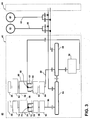
- FIG. 3 is a schematic block diagram of an electrical power system architecture 40 for a gas turbine engine that is modeled with a real-time high fidelity simulation according to an embodiment of the invention.
- the complexity of the system architecture 40 of a modern gas turbine engine helps place in context the method of modeling shown in FIG. 1 and the necessity of a GPGPU-based supercomputing cluster for computation of the method.
- the system architecture 40 includes multiple engine systems, shown herein as including at least a left engine system 42 and a right engine system 44.
- the left and right engine systems 42, 44 may be substantially identical; therefore, only the left engine system 42 will be described in detail for the sake of brevity.
- the left engine system 42 can include the HP and LP spools 26, 28 of the gas turbine engine, although the system architecture 40 has application to other engines as well.
- the left engine system 42 shown herein uses mechanical power provided by two spools, the HP spool 26 and the LP spool 28.
- the system architecture 40 can further include an auxiliary power unit (APU) 46 of the aircraft and an external power source (EPS) 48.
- APU auxiliary power unit
- EPS 48 external power source
- the APU 46 and EPS 48 each have a DC output 50, 52, respectively.
- the left engine system 42 includes a first autotransformer unit (ATU) integrated generator 56, shown herein as an ATU integrated starter-generator 56, configured to produce variable frequency (VF) AC power from mechanical power supplied by the HP spool 26, and a second ATU integrated generator 58 configured to produce constant frequency (CF) AC power from mechanical power supplied by the LP spool 28.
- ATU autotransformer unit
- the ATU integrated starter-generator 56 includes a power generation section 60 and an ATU section 62.
- the ATU section 62 is integrated with the power generation section 60 by integrating some of the electrical windings necessary for power transformation on the electrical winding of the power generation section 60.
- the HP spool 26 can be operably coupled with the ATU integrated starter-generator 56 by an HP drive assembly having an input mechanically coupled to the HP spool 26 and an output mechanically coupled to the power generation section 62.
- the ATU integrated starter-generator 56 can be mounted and coupled to the accessory gearbox 64. Within the accessory gearbox 64, power may also be transferred to other engine accessories.
- the power generation section 60 of the ATU integrated starter-generator 56 converts mechanical power supplied by the HP spool 26 into electrical power and produces a power supply 66 having three phase outputs.
- the ATU section 62 of the ATU integrated starter-generator 56 functions to both transform the three phase outputs of the power supply 66 into a nine phase power output 68 and to step up the voltage of the power supply.
- the ATU integrated starter-generator 56 also provides a starting function to the aircraft.
- the ATU integrated generator 56 on the HP side of the left engine system 42 may comprise a generator that does not provide a starting function to the aircraft.
- a separate starter motor connected to the accessory gearbox 60 can be provided to perform the starting function for the aircraft.
- the left engine system 42 can include multiple generators drawing mechanical power from the HP spool 26 to produce power in order to provide a measure of redundancy.
- the ATU integrated generator 58 includes a power generation section 70 and an ATU section 72.
- the LP spool 28 can be operably coupled with the ATU integrated generator 58 by an LP drive assembly having an input mechanically coupled to the LP spool 28 and an output mechanically coupled to the power generation section 70.
- the constant speed drive (CSD) 74 can be mechanically coupled to the ATU integrated generator 58 and drives the power generation section 70 at a constant speed.
- the power generation section 70 of the ATU integrated generator 58 converts mechanical power supplied by the LP spool 28 into electrical power and produces a power supply 76 having three phase outputs.
- the ATU section 72 of the ATU integrated generator 58 functions to both transform the three phase outputs of the power supply 76 into a nine phase power output 78 and to step up the voltage of the power supply. Due to the CSD, the power supplies 66, 76 will have constant frequency.
Landscapes
- Physics & Mathematics (AREA)
- General Physics & Mathematics (AREA)
- Engineering & Computer Science (AREA)
- Automation & Control Theory (AREA)
- Supply And Distribution Of Alternating Current (AREA)
- Remote Monitoring And Control Of Power-Distribution Networks (AREA)
Applications Claiming Priority (1)
| Application Number | Priority Date | Filing Date | Title |
|---|---|---|---|
| US13/647,671 US9383738B2 (en) | 2012-10-09 | 2012-10-09 | Method for high fidelity modeling of an aircraft electrical power system |
Publications (2)
| Publication Number | Publication Date |
|---|---|
| EP2738630A1 EP2738630A1 (en) | 2014-06-04 |
| EP2738630B1 true EP2738630B1 (en) | 2016-08-10 |
Family
ID=49484076
Family Applications (1)
| Application Number | Title | Priority Date | Filing Date |
|---|---|---|---|
| EP13187576.7A Not-in-force EP2738630B1 (en) | 2012-10-09 | 2013-10-07 | Method for high fidelity modeling of an aircraft electrical power system |
Country Status (6)
Families Citing this family (4)
| Publication number | Priority date | Publication date | Assignee | Title |
|---|---|---|---|---|
| US9646114B2 (en) * | 2013-07-10 | 2017-05-09 | The Boeing Company | Electrical power system stability |
| CN104915470B (zh) * | 2015-05-11 | 2017-12-22 | 中国民航大学 | 基于飞机电力系统动态特性的广义状态空间平均建模方法 |
| WO2017010203A1 (ja) * | 2015-07-14 | 2017-01-19 | 株式会社村田製作所 | 電子部品の設計装置、該設計装置で用いるシミュレーション方法及びコンピュータプログラム |
| US10248430B2 (en) | 2016-12-16 | 2019-04-02 | Hamilton Sundstrand Corporation | Runtime reconfigurable dissimilar processing platform |
Family Cites Families (6)
| Publication number | Priority date | Publication date | Assignee | Title |
|---|---|---|---|---|
| JPH0876814A (ja) * | 1994-07-01 | 1996-03-22 | Hitachi Ltd | 電磁駆動装置のシミュレータ及び電磁駆動装置をシミュレータで制御する電磁駆動システム |
| US7178125B1 (en) | 2004-07-07 | 2007-02-13 | Optimal Corporation | Method for modeling triangle meshed interconnect structures using an electrically equivalent three rectangle combination for each triangle in the triangle mesh |
| US20070211840A1 (en) | 2006-02-17 | 2007-09-13 | International Business Machines Corporation | Methods and apparatus for analyzing transmission lines with decoupling of connectors and other circuit elements |
| US9063882B1 (en) * | 2010-09-09 | 2015-06-23 | Sas Ip, Inc. | Matrix preconditioners for simulations of physical fields |
| US8510091B1 (en) * | 2010-09-09 | 2013-08-13 | Sas Ip, Inc. | Domain decomposition formulations for simulating electromagnetic fields |
| US8924186B1 (en) * | 2010-09-09 | 2014-12-30 | Sas Ip, Inc. | Simulations of physical systems for multiple excitations |
-
2012
- 2012-10-09 US US13/647,671 patent/US9383738B2/en active Active
-
2013
- 2013-10-03 CA CA2829683A patent/CA2829683C/en not_active Expired - Fee Related
- 2013-10-04 JP JP2013208697A patent/JP2014078227A/ja active Pending
- 2013-10-07 EP EP13187576.7A patent/EP2738630B1/en not_active Not-in-force
- 2013-10-08 BR BR102013025954A patent/BR102013025954A8/pt not_active IP Right Cessation
- 2013-10-09 CN CN201310467084.5A patent/CN103823915B/zh active Active
Also Published As
| Publication number | Publication date |
|---|---|
| CA2829683A1 (en) | 2014-04-09 |
| BR102013025954A8 (pt) | 2015-12-29 |
| US20140100826A1 (en) | 2014-04-10 |
| JP2014078227A (ja) | 2014-05-01 |
| BR102013025954A2 (pt) | 2015-11-24 |
| CN103823915B (zh) | 2019-07-16 |
| EP2738630A1 (en) | 2014-06-04 |
| CA2829683C (en) | 2017-11-07 |
| CN103823915A (zh) | 2014-05-28 |
| US9383738B2 (en) | 2016-07-05 |
Similar Documents
| Publication | Publication Date | Title |
|---|---|---|
| Dufour et al. | Hardware-in-the-loop testing of modern on-board power systems using digital twins | |
| Guironnet et al. | Towards an open-source solution using Modelica for time-domain simulation of power systems | |
| CN107633155B (zh) | 用于组件故障树的基于计算机的生成的方法和设备 | |
| EP2738630B1 (en) | Method for high fidelity modeling of an aircraft electrical power system | |
| US20070094184A1 (en) | Solving constraint satisfaction problems with duplicated sub-problems | |
| Vermaak et al. | Virtual commissioning: A tool to ensure effective system integration | |
| Diao et al. | On parallelizing single dynamic simulation using HPC techniques and APIs of commercial software | |
| WO2018102720A1 (en) | System and method for a fast power network simulator | |
| CN103700036A (zh) | 一种适于电力系统多时间尺度的暂态稳定性投影积分方法 | |
| Prais et al. | Operator training simulator: algorithms and test result | |
| Čech et al. | Novel tools for model-based control system design based on FMI/FMU standard with application in energetics | |
| CN102184136B (zh) | 一种验证aadl模型运行状态与需求一致性的方法 | |
| Chen et al. | ArchME: A Systems Modeling Language extension for mechatronic system architecture modeling | |
| CN109002645A (zh) | 动车组子系统建模方法及装置 | |
| Guo et al. | A cloud simulation based environment for multi-disciplinary collaborative simulation and optimization | |
| JP2011186991A (ja) | 常微分方程式を解くための方法、プログラム及びシステム | |
| Rahman et al. | Modeling and design of mechatronics system with SysML, Simscape and Simulink | |
| Nuzzo et al. | Platform-based design methodology and modeling for aircraft electric power systems | |
| CN114579084A (zh) | 发动机的控制软件的形式化处理方法和装置 | |
| Bélanger et al. | Modern methodology of electric system design using rapid-control prototyping and hardware-in-the-loop | |
| Peng et al. | Multi‐rate electromagnetic transient simulation of large‐scale power system based on multi‐core | |
| Lu et al. | An investigation of model-based design framework for aero-engine control systems | |
| Lytle | Multi-fidelity simulations of air breathing propulsion systems | |
| CN109508260A (zh) | 一种自修复处理器对锁步系统的可靠性建模与分析方法 | |
| Tabunshchyk et al. | Poster: An Open Modular Approach for the Design and Verification of the Electric Vehicles |
Legal Events
| Date | Code | Title | Description |
|---|---|---|---|
| PUAI | Public reference made under article 153(3) epc to a published international application that has entered the european phase |
Free format text: ORIGINAL CODE: 0009012 |
|
| 17P | Request for examination filed |
Effective date: 20131007 |
|
| AK | Designated contracting states |
Kind code of ref document: A1 Designated state(s): AL AT BE BG CH CY CZ DE DK EE ES FI FR GB GR HR HU IE IS IT LI LT LU LV MC MK MT NL NO PL PT RO RS SE SI SK SM TR |
|
| AX | Request for extension of the european patent |
Extension state: BA ME |
|
| R17P | Request for examination filed (corrected) |
Effective date: 20141204 |
|
| RBV | Designated contracting states (corrected) |
Designated state(s): AL AT BE BG CH CY CZ DE DK EE ES FI FR GB GR HR HU IE IS IT LI LT LU LV MC MK MT NL NO PL PT RO RS SE SI SK SM TR |
|
| GRAP | Despatch of communication of intention to grant a patent |
Free format text: ORIGINAL CODE: EPIDOSNIGR1 |
|
| INTG | Intention to grant announced |
Effective date: 20160322 |
|
| GRAS | Grant fee paid |
Free format text: ORIGINAL CODE: EPIDOSNIGR3 |
|
| GRAA | (expected) grant |
Free format text: ORIGINAL CODE: 0009210 |
|
| AK | Designated contracting states |
Kind code of ref document: B1 Designated state(s): AL AT BE BG CH CY CZ DE DK EE ES FI FR GB GR HR HU IE IS IT LI LT LU LV MC MK MT NL NO PL PT RO RS SE SI SK SM TR |
|
| REG | Reference to a national code |
Ref country code: GB Ref legal event code: FG4D |
|
| REG | Reference to a national code |
Ref country code: CH Ref legal event code: EP Ref country code: AT Ref legal event code: REF Ref document number: 819590 Country of ref document: AT Kind code of ref document: T Effective date: 20160815 |
|
| REG | Reference to a national code |
Ref country code: IE Ref legal event code: FG4D |
|
| REG | Reference to a national code |
Ref country code: DE Ref legal event code: R096 Ref document number: 602013010229 Country of ref document: DE |
|
| REG | Reference to a national code |
Ref country code: FR Ref legal event code: PLFP Year of fee payment: 4 |
|
| REG | Reference to a national code |
Ref country code: LT Ref legal event code: MG4D |
|
| REG | Reference to a national code |
Ref country code: NL Ref legal event code: MP Effective date: 20160810 |
|
| REG | Reference to a national code |
Ref country code: AT Ref legal event code: MK05 Ref document number: 819590 Country of ref document: AT Kind code of ref document: T Effective date: 20160810 |
|
| PG25 | Lapsed in a contracting state [announced via postgrant information from national office to epo] |
Ref country code: FI Free format text: LAPSE BECAUSE OF FAILURE TO SUBMIT A TRANSLATION OF THE DESCRIPTION OR TO PAY THE FEE WITHIN THE PRESCRIBED TIME-LIMIT Effective date: 20160810 Ref country code: LT Free format text: LAPSE BECAUSE OF FAILURE TO SUBMIT A TRANSLATION OF THE DESCRIPTION OR TO PAY THE FEE WITHIN THE PRESCRIBED TIME-LIMIT Effective date: 20160810 Ref country code: RS Free format text: LAPSE BECAUSE OF FAILURE TO SUBMIT A TRANSLATION OF THE DESCRIPTION OR TO PAY THE FEE WITHIN THE PRESCRIBED TIME-LIMIT Effective date: 20160810 Ref country code: IT Free format text: LAPSE BECAUSE OF FAILURE TO SUBMIT A TRANSLATION OF THE DESCRIPTION OR TO PAY THE FEE WITHIN THE PRESCRIBED TIME-LIMIT Effective date: 20160810 Ref country code: IS Free format text: LAPSE BECAUSE OF FAILURE TO SUBMIT A TRANSLATION OF THE DESCRIPTION OR TO PAY THE FEE WITHIN THE PRESCRIBED TIME-LIMIT Effective date: 20161210 Ref country code: NL Free format text: LAPSE BECAUSE OF FAILURE TO SUBMIT A TRANSLATION OF THE DESCRIPTION OR TO PAY THE FEE WITHIN THE PRESCRIBED TIME-LIMIT Effective date: 20160810 Ref country code: HR Free format text: LAPSE BECAUSE OF FAILURE TO SUBMIT A TRANSLATION OF THE DESCRIPTION OR TO PAY THE FEE WITHIN THE PRESCRIBED TIME-LIMIT Effective date: 20160810 Ref country code: NO Free format text: LAPSE BECAUSE OF FAILURE TO SUBMIT A TRANSLATION OF THE DESCRIPTION OR TO PAY THE FEE WITHIN THE PRESCRIBED TIME-LIMIT Effective date: 20161110 |
|
| PG25 | Lapsed in a contracting state [announced via postgrant information from national office to epo] |
Ref country code: PL Free format text: LAPSE BECAUSE OF FAILURE TO SUBMIT A TRANSLATION OF THE DESCRIPTION OR TO PAY THE FEE WITHIN THE PRESCRIBED TIME-LIMIT Effective date: 20160810 Ref country code: LV Free format text: LAPSE BECAUSE OF FAILURE TO SUBMIT A TRANSLATION OF THE DESCRIPTION OR TO PAY THE FEE WITHIN THE PRESCRIBED TIME-LIMIT Effective date: 20160810 Ref country code: PT Free format text: LAPSE BECAUSE OF FAILURE TO SUBMIT A TRANSLATION OF THE DESCRIPTION OR TO PAY THE FEE WITHIN THE PRESCRIBED TIME-LIMIT Effective date: 20161212 Ref country code: BE Free format text: LAPSE BECAUSE OF NON-PAYMENT OF DUE FEES Effective date: 20161031 Ref country code: ES Free format text: LAPSE BECAUSE OF FAILURE TO SUBMIT A TRANSLATION OF THE DESCRIPTION OR TO PAY THE FEE WITHIN THE PRESCRIBED TIME-LIMIT Effective date: 20160810 Ref country code: GR Free format text: LAPSE BECAUSE OF FAILURE TO SUBMIT A TRANSLATION OF THE DESCRIPTION OR TO PAY THE FEE WITHIN THE PRESCRIBED TIME-LIMIT Effective date: 20161111 Ref country code: SE Free format text: LAPSE BECAUSE OF FAILURE TO SUBMIT A TRANSLATION OF THE DESCRIPTION OR TO PAY THE FEE WITHIN THE PRESCRIBED TIME-LIMIT Effective date: 20160810 Ref country code: AT Free format text: LAPSE BECAUSE OF FAILURE TO SUBMIT A TRANSLATION OF THE DESCRIPTION OR TO PAY THE FEE WITHIN THE PRESCRIBED TIME-LIMIT Effective date: 20160810 |
|
| PG25 | Lapsed in a contracting state [announced via postgrant information from national office to epo] |
Ref country code: EE Free format text: LAPSE BECAUSE OF FAILURE TO SUBMIT A TRANSLATION OF THE DESCRIPTION OR TO PAY THE FEE WITHIN THE PRESCRIBED TIME-LIMIT Effective date: 20160810 Ref country code: RO Free format text: LAPSE BECAUSE OF FAILURE TO SUBMIT A TRANSLATION OF THE DESCRIPTION OR TO PAY THE FEE WITHIN THE PRESCRIBED TIME-LIMIT Effective date: 20160810 |
|
| REG | Reference to a national code |
Ref country code: DE Ref legal event code: R119 Ref document number: 602013010229 Country of ref document: DE |
|
| PG25 | Lapsed in a contracting state [announced via postgrant information from national office to epo] |
Ref country code: SK Free format text: LAPSE BECAUSE OF FAILURE TO SUBMIT A TRANSLATION OF THE DESCRIPTION OR TO PAY THE FEE WITHIN THE PRESCRIBED TIME-LIMIT Effective date: 20160810 Ref country code: CZ Free format text: LAPSE BECAUSE OF FAILURE TO SUBMIT A TRANSLATION OF THE DESCRIPTION OR TO PAY THE FEE WITHIN THE PRESCRIBED TIME-LIMIT Effective date: 20160810 Ref country code: BG Free format text: LAPSE BECAUSE OF FAILURE TO SUBMIT A TRANSLATION OF THE DESCRIPTION OR TO PAY THE FEE WITHIN THE PRESCRIBED TIME-LIMIT Effective date: 20161110 Ref country code: SM Free format text: LAPSE BECAUSE OF FAILURE TO SUBMIT A TRANSLATION OF THE DESCRIPTION OR TO PAY THE FEE WITHIN THE PRESCRIBED TIME-LIMIT Effective date: 20160810 Ref country code: DK Free format text: LAPSE BECAUSE OF FAILURE TO SUBMIT A TRANSLATION OF THE DESCRIPTION OR TO PAY THE FEE WITHIN THE PRESCRIBED TIME-LIMIT Effective date: 20160810 Ref country code: BE Free format text: LAPSE BECAUSE OF FAILURE TO SUBMIT A TRANSLATION OF THE DESCRIPTION OR TO PAY THE FEE WITHIN THE PRESCRIBED TIME-LIMIT Effective date: 20160810 |
|
| REG | Reference to a national code |
Ref country code: CH Ref legal event code: PL |
|
| PLBE | No opposition filed within time limit |
Free format text: ORIGINAL CODE: 0009261 |
|
| STAA | Information on the status of an ep patent application or granted ep patent |
Free format text: STATUS: NO OPPOSITION FILED WITHIN TIME LIMIT |
|
| 26N | No opposition filed |
Effective date: 20170511 |
|
| REG | Reference to a national code |
Ref country code: IE Ref legal event code: MM4A |
|
| PG25 | Lapsed in a contracting state [announced via postgrant information from national office to epo] |
Ref country code: LI Free format text: LAPSE BECAUSE OF NON-PAYMENT OF DUE FEES Effective date: 20161031 Ref country code: CH Free format text: LAPSE BECAUSE OF NON-PAYMENT OF DUE FEES Effective date: 20161031 Ref country code: DE Free format text: LAPSE BECAUSE OF NON-PAYMENT OF DUE FEES Effective date: 20170503 |
|
| PG25 | Lapsed in a contracting state [announced via postgrant information from national office to epo] |
Ref country code: LU Free format text: LAPSE BECAUSE OF NON-PAYMENT OF DUE FEES Effective date: 20161007 Ref country code: SI Free format text: LAPSE BECAUSE OF FAILURE TO SUBMIT A TRANSLATION OF THE DESCRIPTION OR TO PAY THE FEE WITHIN THE PRESCRIBED TIME-LIMIT Effective date: 20160810 |
|
| REG | Reference to a national code |
Ref country code: FR Ref legal event code: PLFP Year of fee payment: 5 |
|
| PG25 | Lapsed in a contracting state [announced via postgrant information from national office to epo] |
Ref country code: IE Free format text: LAPSE BECAUSE OF NON-PAYMENT OF DUE FEES Effective date: 20161007 |
|
| PGFP | Annual fee paid to national office [announced via postgrant information from national office to epo] |
Ref country code: FR Payment date: 20171025 Year of fee payment: 5 |
|
| PGFP | Annual fee paid to national office [announced via postgrant information from national office to epo] |
Ref country code: GB Payment date: 20171027 Year of fee payment: 5 |
|
| PG25 | Lapsed in a contracting state [announced via postgrant information from national office to epo] |
Ref country code: HU Free format text: LAPSE BECAUSE OF FAILURE TO SUBMIT A TRANSLATION OF THE DESCRIPTION OR TO PAY THE FEE WITHIN THE PRESCRIBED TIME-LIMIT; INVALID AB INITIO Effective date: 20131007 |
|
| PG25 | Lapsed in a contracting state [announced via postgrant information from national office to epo] |
Ref country code: MK Free format text: LAPSE BECAUSE OF FAILURE TO SUBMIT A TRANSLATION OF THE DESCRIPTION OR TO PAY THE FEE WITHIN THE PRESCRIBED TIME-LIMIT Effective date: 20160810 Ref country code: CY Free format text: LAPSE BECAUSE OF FAILURE TO SUBMIT A TRANSLATION OF THE DESCRIPTION OR TO PAY THE FEE WITHIN THE PRESCRIBED TIME-LIMIT Effective date: 20160810 Ref country code: MC Free format text: LAPSE BECAUSE OF FAILURE TO SUBMIT A TRANSLATION OF THE DESCRIPTION OR TO PAY THE FEE WITHIN THE PRESCRIBED TIME-LIMIT Effective date: 20160810 Ref country code: MT Free format text: LAPSE BECAUSE OF NON-PAYMENT OF DUE FEES Effective date: 20161031 |
|
| PG25 | Lapsed in a contracting state [announced via postgrant information from national office to epo] |
Ref country code: AL Free format text: LAPSE BECAUSE OF FAILURE TO SUBMIT A TRANSLATION OF THE DESCRIPTION OR TO PAY THE FEE WITHIN THE PRESCRIBED TIME-LIMIT Effective date: 20160810 Ref country code: TR Free format text: LAPSE BECAUSE OF FAILURE TO SUBMIT A TRANSLATION OF THE DESCRIPTION OR TO PAY THE FEE WITHIN THE PRESCRIBED TIME-LIMIT Effective date: 20160810 |
|
| GBPC | Gb: european patent ceased through non-payment of renewal fee |
Effective date: 20181007 |
|
| PG25 | Lapsed in a contracting state [announced via postgrant information from national office to epo] |
Ref country code: FR Free format text: LAPSE BECAUSE OF NON-PAYMENT OF DUE FEES Effective date: 20181031 |
|
| PG25 | Lapsed in a contracting state [announced via postgrant information from national office to epo] |
Ref country code: GB Free format text: LAPSE BECAUSE OF NON-PAYMENT OF DUE FEES Effective date: 20181007 |